Gilbarco MRIR6 Radio Frequency Identification Device (Limited Mod User Manual
Gilbarco Inc. Radio Frequency Identification Device (Limited Mod
UserManual.wiki
>
Gilbarco
>
MRIR6 User Manual
>
Users Manual
Contents
1.
Users Manual
2.
Cover letter for confidentiality
Users Manual
Navigation menu
Upload a User Manual
Namespaces
Wiki Guide
HTML
PDF
Info
Views
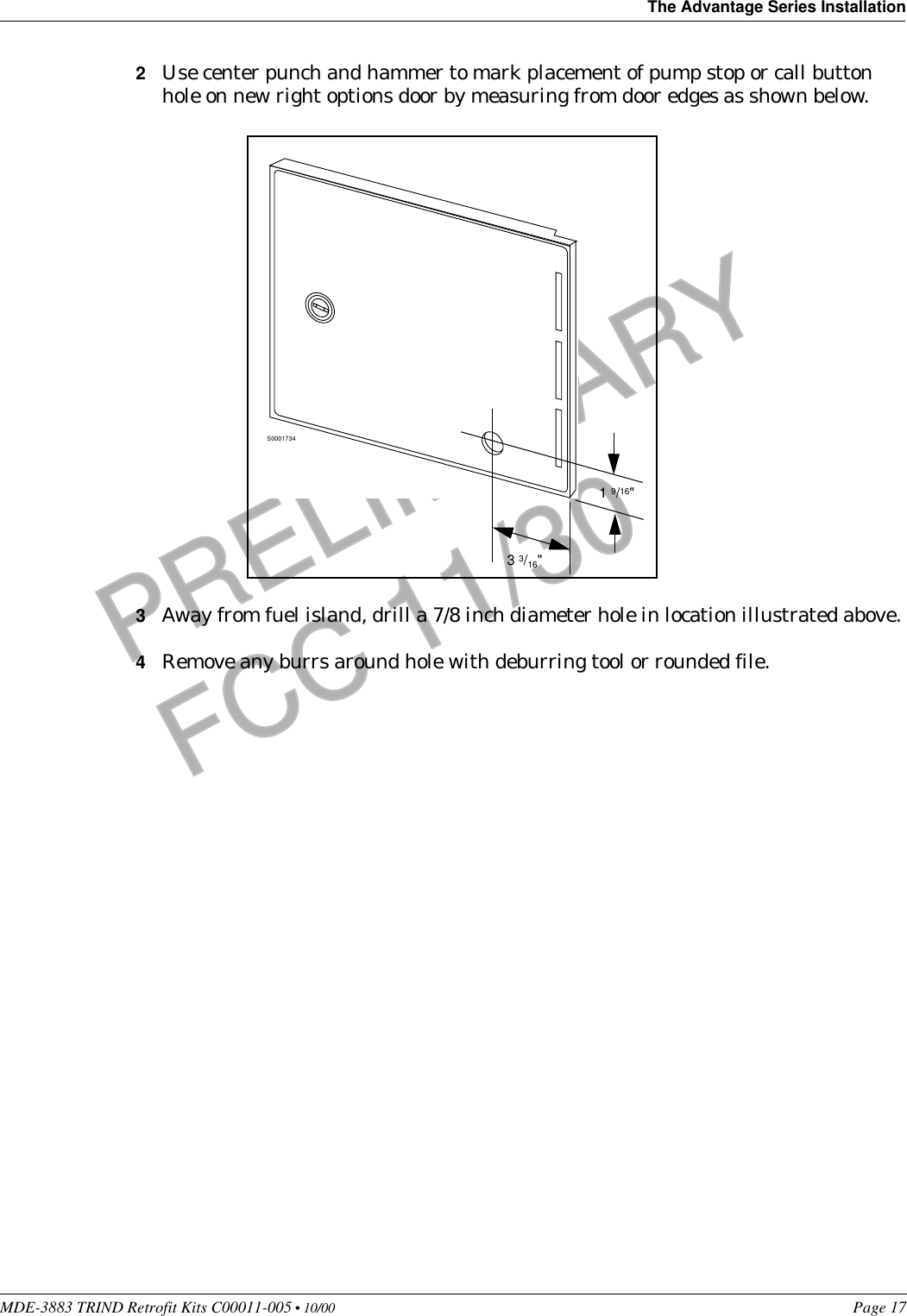
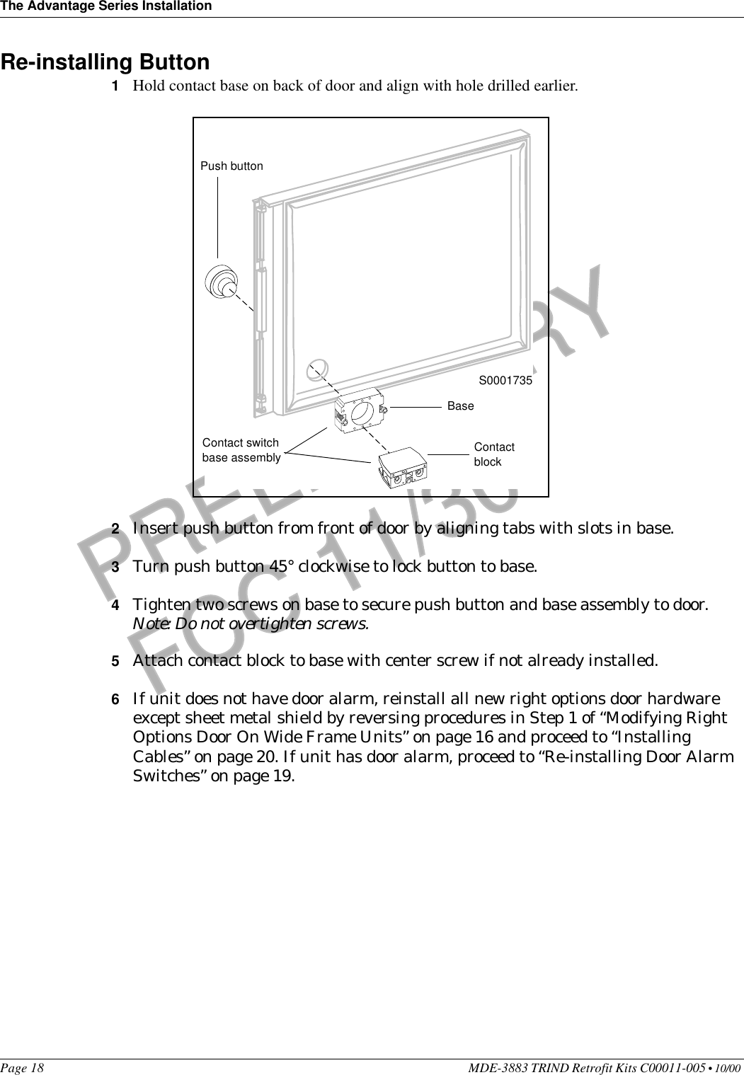
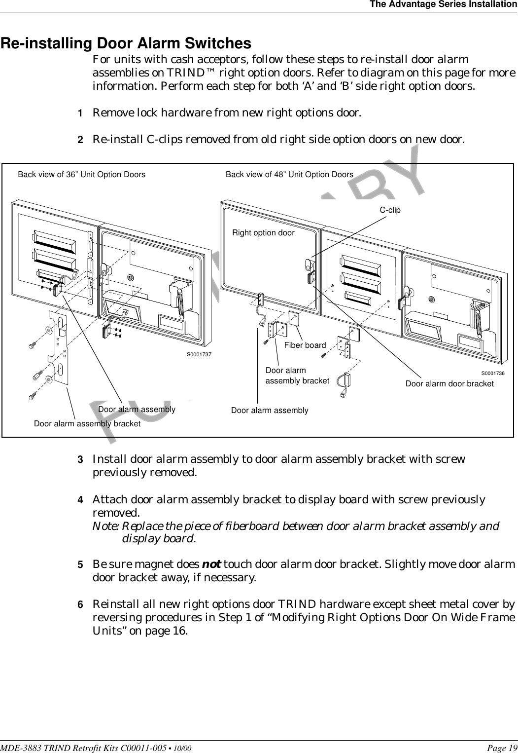
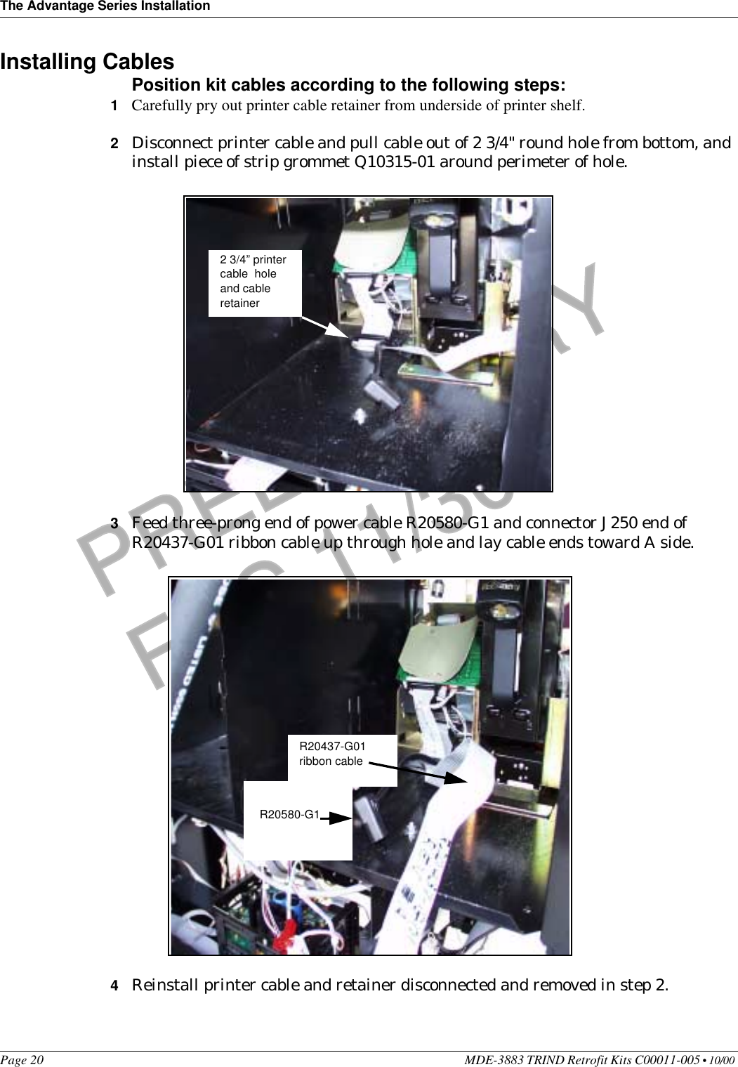
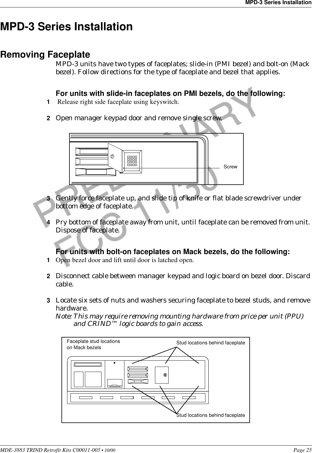
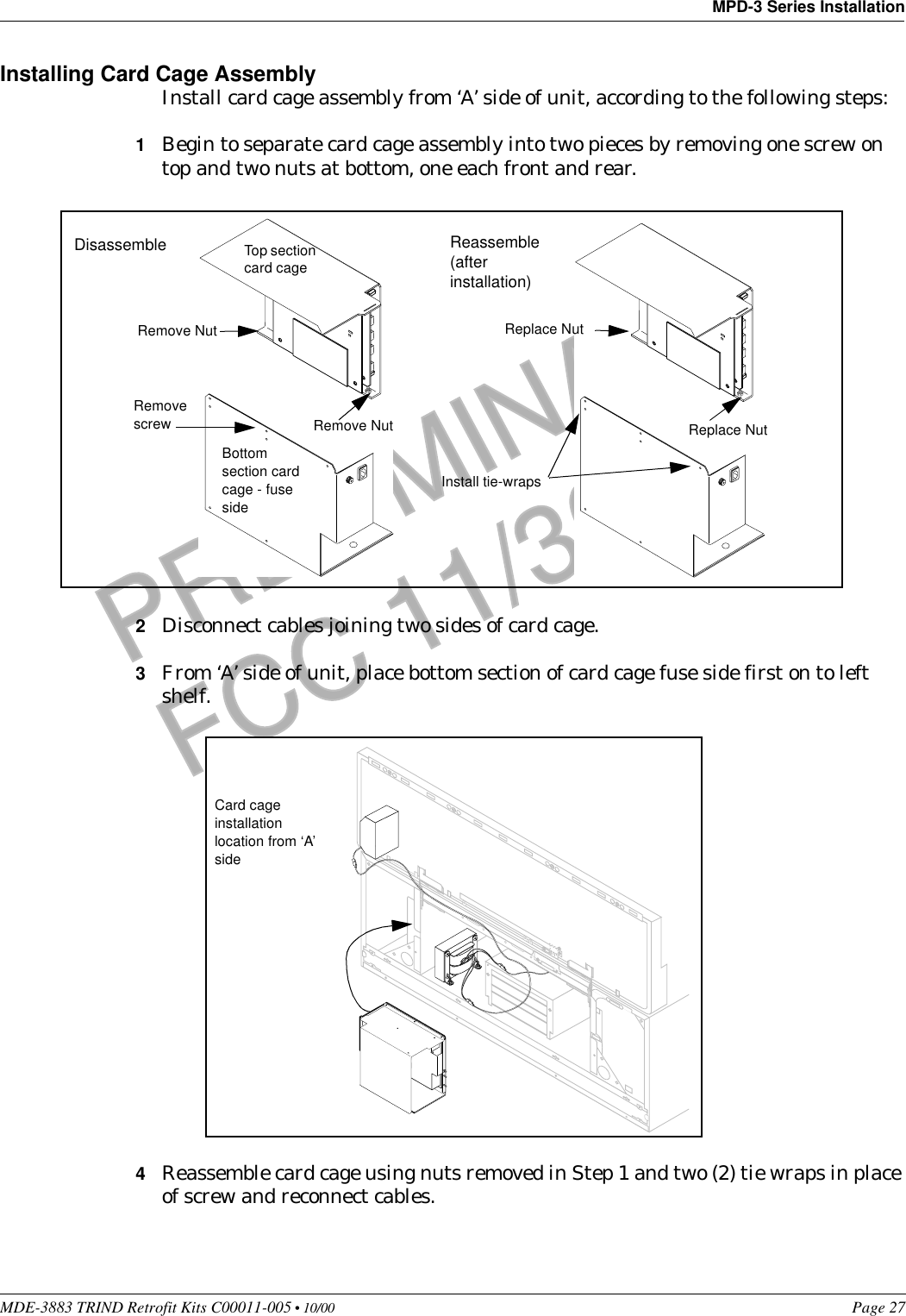
User Manual
Discussion / Help
Navigation