Gilbarco MRIR6 Radio Frequency Identification Device (Limited Mod User Manual
Gilbarco Inc. Radio Frequency Identification Device (Limited Mod
Gilbarco >
Contents
- 1. Users Manual
- 2. Cover letter for confidentiality
Users Manual

PRELIMINARY
FCC 11/30
MDE-3883 TRIND Retrofit Kits C00011-005 • 10/00 Page 1
Introduction
Purpose of this Manual
This manual provides instruction for installing TRIND™ Retrofit Kits C00011-
005-XX in The Advantage® Series wide frame and narrow frame units and MPD®3
units with InfoScreen®, monochrome CRIND®, or single-line CRIND.
The TRIND option allows customers to automatically authorize CRIND-equipped
units using a hand-held transponder tag provided by a major oil company (MOC).
Use these kits for one- or two-sided units.
Prerequisites
Before installing the TRIND kit, ensure that the existing CRIND has the Z-180
logic board T17764-XX, which is not provided in TRIND retrofit kit.
Important Notice
This equipment has been tested and found to comply with the limits for a Class A
digital device pursuant to Part 15 of the FCC Rules. These limits are designed to
provide reasonable protection against harmful interference when the equipment
is operated in a commercial environment. This equipment generates, uses and
can radiate radio frequency energy, and if not installed and used in accordance
with the instruction manual, may cause harmful interference to radio
communications. Operation of this equipment in a residential area is likely to
cause harmful interference in which case the user will be required to correct the
interference at his own expense. Changes or modifications not expressly approved
by the manufacturer could void the user’s authority to operate this equipment.
Required Reading
Before installing the equipment, the installer must read, understand, and follow:
•this manual
•NFPA 30A, The Automotive and Marine Service Station Code
•NFPA 70, The National Electric Code
•applicable federal, state and local codes and regulations
Failure to do so may adversely effect the safe use and operation of the equipment.
Note: This kit must be installed by a Gilbarco ASC (Authorized Service Contractor)
to insure warranty.
MDE-3883
TRIND™
Transmitter/Receiver in Dispenser
Retrofit Kits C00011-005-XX
Installation

Introduction
Page 2 MDE-3883 TRIND Retrofit Kits C00011-005 • 10/00
PRELIMINARY
FCC 11/30
Related Documents
MDE-2531 Pump & Dispenser Start-Up & Service Manual
MDE-2562 CRIND Service Manual
MDE-2628 Cash Acceptor Retrofit Assemblies for The Advantage Series with
CRIND
MDE-2620 Graphics Panel Application for The Advantage Series
PT-1728 The Advantage Series Illustrated Parts Manual
PT-1736 CRIND Card Reader Illustrated Parts Manual
Required Tools
The following equipment is needed to install all TRIND™ Multi 1 kits:
•Allen wrench set, American standard
•clean cloth or rag
•chip extraction tool, e.g., IC extraction, Digikey Part No. K158-ND or
equivalent
•isopropyl alcohol (part# END-1082)
•needle nose pliers
•nut driver, 1/4'', 3/8''
•pocket knife
•Q12534 CRIND diagnostic card
•ratchet set, standard
•screwdrivers, flat and Phillips head
•static guard wrist strap
The following additional tools are required if kit is to be installed on wide
frame units with call or stop button on existing right options door:
•center punch
•deburring tool or round file
•hand drill, battery electric or pneumatic
•light hammer
•pilot drill bit (between 3/32” and 1/4”) and 7/8” drill bit
•standard tape measure or rule

MDE-3883 TRIND Retrofit Kits C00011-005 • 10/00 Page 3
Parts Lists
PRELIMINARY
FCC 11/30
Parts Lists
TRIND Software
CRIND BIOS TRIND software K93744-XX is an order entry item for all kits.
Q13863-04 Cable Group for All The Advantage Series Kits
Cable group Q13863-04 for all kits contains the following cables:
C00011-005 Kits for The Advantage Series Wide Frame Units
Kits C00011-005-WF-D (dual-sided) and C00011-005-WF-S (single-sided)
for The Advantage Series Wide Frames (48’’) contain the following parts.
Cables Part Number Quantity per kit
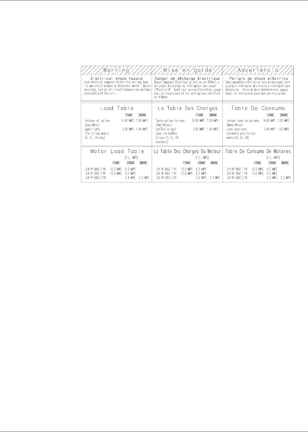
Gateway to CRIND logic R20437-G01 1
AC power R20580-G1 1
Light/Multi-protocol Reader R20773-G2 2
Description Part Number Quantity
cable clamp, gray Q13558-04 16
cable group Q13863-04 For components see table “Q13863-04 Cable
Group for All The Advantage Series Kits” on
page 3.
cable tie Q10178-01 4
card cage assembly T20606-G3 (see note 3) 1
door assembly, right options clear with
TRIND
T20613-G1 or
T20613-G2 (see note 1)
1 per side
graphics, right option door AD05002GW00X (see note 2)
grommet strip, solid Q10315-01 1.5 ft.
jump jack Q11011-01 4
label plate, FCC N23949-06 1
manual, installation instructions MDE-3883 1
nut Q12068-03 2
screw, phillips 6-32 Q12083-13 1
screw, phillips 8-32 Q12083-26 2
Notes:
1. T20613-02 door assembly is call/stop button ready.
2. Right Option Door Graphics AD05002GW00X are an order entry item.
3. Some kits may contain a T20606-G4 Card Cage. Only differences for installation consist of location of Gateway
board (on top of card cage in -G4 units, within card cage for -03 units) and card cage harness cables for connecting
to R20773-G2 door cables. All harness cable connections are identical between -G3 and -G4 card cages. See
“Addressing Gateway Board” on page 35.

Parts Lists
Page 4 MDE-3883 TRIND Retrofit Kits C00011-005 • 10/00
PRELIMINARY
FCC 11/30
C00011-005 Kits for The Advantage Series Narrow Frame Units
Kits C00011-005-NF-D (dual-sided) and C00011-005-NF-S (single-sided)
for The Advantage Series Narrow Frames (36’’) contain the following
parts.
Description Part Number Quantity
cable clamp, gray Q13558-04 16
cable group Q13863-04 For components see table “Q13863-04 Cable
Group for All The Advantage Series Kits” on
page 3.
cable tie Q10178-01 4
card cage assembly T20606-G3 (see note
1)
1
door assembly, right options clear with
TRIND
T20614-G1 1 per side
graphics, right option door AD02002GN00X (see note 2)
grommet strip, solid Q10315-01 1.5 ft.
jump jack Q11011-01 4
label plate, FCC N23949-06 1
manual, installation instructions MDE-3883 1
nut Q12068-03 2
screw, phillips 6-32 Q12083-13 1
screw, phillips 8-32 Q12083-26 2
Notes:
1. Some kits may contain a T20606-G4 Card Cage. Only differences for installation consist of location of Gateway
board (on top of card cage in -G4 units, within card cage for -03 units) and card cage harness cables for connecting
to R20773-G2 door cables. All harness cable connections are identical between -G3 and -G4 card cages. See
“Addressing Gateway Board” on page 35.
2. Right Option Door Graphics AD02002GN00X are an order entry item.

MDE-3883 TRIND Retrofit Kits C00011-005 • 10/00 Page 5
Parts Lists
PRELIMINARY
FCC 11/30
C00011-005 Kits for The MPD-3 Series Units
Kit for MPD-3 units:
All C00012-005 kits for MPD-3 units contain the following parts except as noted
in the tables.
K96646-05 Kit for MPD-3 Units
K96646-05 Kits are configured as order entry for all MPD-3 units and contain the
following parts.
Kit Bezel and Faceplate Type Sides
C00012-005-MPDD PMI Bezel with Slide-In Faceplate 2
C00012-005-MPDS 1
C00012-005-MPBD Mack Bezel with Bolt-On Faceplate 2
C00012-005-MPBS 1
Description Part Number Quantity
bezel assembly T20616-GX (see note 1) 1 per side
cable clamp, gray Q13558-04 16
cable and accessory group K96646-05 For components see table “K96646-05
Kit for MPD-3 Units” on page 5.
cable tie Q10178-01 4
card cage assembly T20606-G3 (see note 3) 1
graphics, bezel MP02002G001 (see note 2)
grommet strip, solid Q10315-01 1.5 ft.
jump jack Q11011-01 4
kit, MPD-3 parts K96646-05( see table below)
label plate, FCC N23949-06 1
manual, installation instructions MDE-3883 1
nut Q12068-03 2
screw, phillips 6-32 Q12083-13 1
screw, phillips 8-32 Q12083-26 2
Notes:
1. Bezels are order entry item. T20616-G1 bezel assemblies are configured for PMI (slide-in) faceplates; T20616-G2
bezel assemblies are configured for bolt-on (stud) Mack bezel units.
2. Bezel Graphics MP02002G001 are an order entry item.
3. Some kits may contain a T20606-G4 Card Cage. Only differences for installation consist of location of Gateway
board (on top of card cage in -G4 units, within card cage for -03 units) and card cage harness cables for connecting
to R20773-G2 door cables. All harness cable connections are identical between -G3 and -G4 card cages. See
“Addressing Gateway Board” on page 35.
Description Part Number Quantity
cable R18163-G1 1
cable group Q13863-05
Cable group contains the following parts:
•Gateway to CRIND logic R20437-G01, 1 ea.
•AC power R20580-G1, 1 ea.
1
manager keypad assembly T17549-G1 1
Important Safety Information
Page 6 MDE-3883 TRIND Retrofit Kits C00011-005 • 10/00
PRELIMINARY
FCC 11/30
Important Safety Information
This section introduces the hazards and safety precautions associated with installing,
inspecting, maintaining or servicing this product. Before performing any task on this product,
read this safety information and the applicable sections in this manual, where additional
hazards and safety precautions for your task will be found. Fire, explosion, electrical shock or
pressure release could occur and cause death or serious injury if these safe service procedures
are not followed.
Preliminary Precautions
You are working in a potentially dangerous environment of flammable fuels, vapors, and high
voltage or pressures. Only trained or authorized individuals knowledgeable in the related
procedures should install, inspect, maintain or service this equipment.
The first and most important information you must know is how to stop all fuel flow to the
pump and island.
Emergency Total Electrical Shut-Off
Locate the switch or circuit breakers that shut-off all power to all fueling equipment,
dispensary devices, and submerged turbine pumps (STPs). These you must operate in the event
of an emergency.
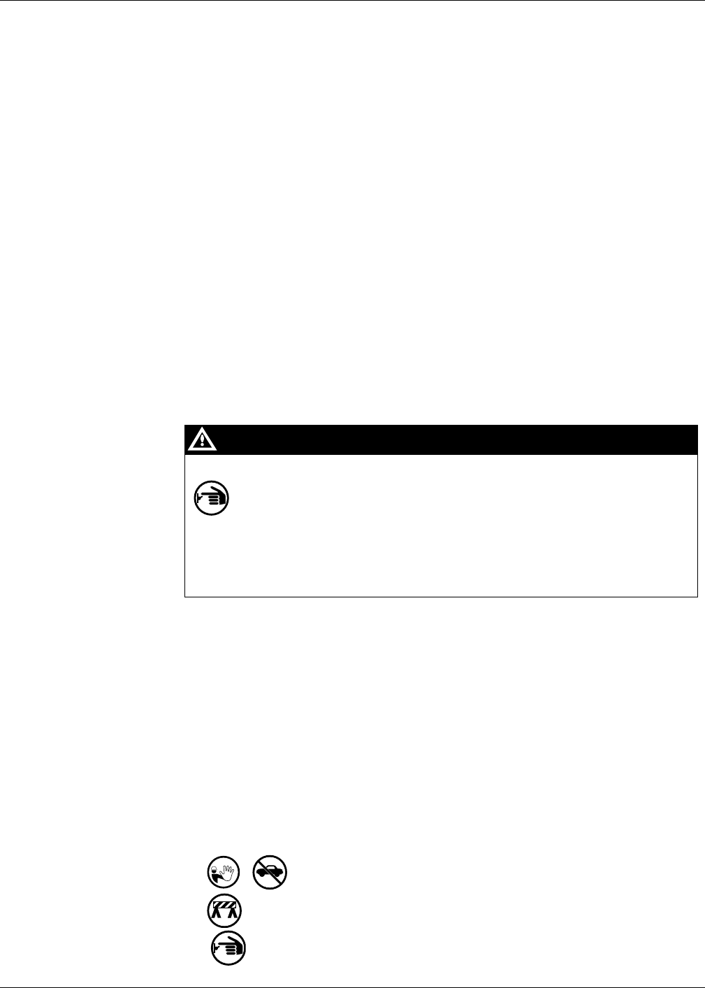
Total Electrical Shut-Off Before Access
Any procedure requiring access to electrical components or the electronics of the dispenser
requires total electrical shut-off of that unit.
NFPA 30A, Section 4-1.2, published by the National Fire Protection Association, requires the
installation of an easily accessible switch or circuit breaker to shut-off the power to all fueling
equipment, dispensing devices and STPs in the event of an emergency. Know the function and
location of this switch or circuit breaker before inspecting, installing, maintaining, or servicing
Marconi equipment.
Evacuation, Barricading and Shut-Off
Any procedures requiring accessing the pump/dispenser or STPs requires the following three
actions:
• An evacuation of all unauthorized persons and vehicles
• Using safety tape or cones as barricades to the effected units
• A total electrical shut-off of that unit
The EMERGENCY STOP, ALL STOP, and PUMP STOP buttons at the cashier’s
station WILL NOT shut off electrical power to the pump/dispenser.
This means that even if you activate these stops, fuel may continue to flow
uncontrolled.
You must used the TOTAL ELECTRICAL SHUT-OFF in the case of an emergency
and not only these cashier station “stops.”
WARNING
MDE-3883 TRIND Retrofit Kits C00011-005 • 10/00 Page 7
Important Safety Information
PRELIMINARY
FCC 11/30
Read the Manual
Read, understand and follow this manual and any other labels or related materials supplied
with this equipment. If you do not understand a procedure, call a Marconi Authorized Service
Contractor or call the Marconi Call Center at 1-800-800-7498. It is imperative to your safety
and the safety of others to understand the procedures before beginning work.
Follow the Regulations
There is applicable information in: NFPA 30A: Automotive and Marine Service Code; NFPA
70: National Electrical Code (NEC); OSHA regulations; and federal, state, and local codes
which must be followed. Failure to install, inspect, maintain or service this equipment in
accordance with these codes, regulations and standards may lead to legal citations with
penalties or affect the safe use and operation of the equipment.
Safety Symbols and Warning Words
This section provides important information about warning symbols and boxes.
Alert Symbol
This safety alert symbol is used in this manual and on warning labels to alert you to a
precaution which must be followed to prevent potential personal safety hazards. Obey safety
directives that follow this symbol to avoid possible injury or death.
Signal Words
These signal words used in this manual and on warning labels tell you the seriousness of
particular safety hazards. The precautions that follow must be followed to prevent death, injury
or damage to the equipment.
This signal word designates a hazard or unsafe practice which may result in minor injury.
This signal word is used to alert you to a hazard or unsafe practice which will result in
death or serious injury.
This alerts you to a hazard or unsafe practice that could result in death or serious injury.
CAUTION
When used by itself, CAUTION designates a hazard or unsafe practice which may result in
property or equipment damage.
CAUTION
DANGER
WARNING
Important Safety Information
Page 8 MDE-3883 TRIND Retrofit Kits C00011-005 • 10/00
PRELIMINARY
FCC 11/30
Prevent Explosions and Fires
Fuels and their vapors will become explosive if ignited. Spilled or leaking fuels cause vapors.
Even filling customer tanks will cause explosive vapors in the vicinity of dispenser or island.
No Open Flames
Open flames from matches, lighters, welding torches or other sources can ignite fuels
and their vapors.
No Sparks - No Smoking
Sparks from starting vehicles, starting or using power tools, burning cigarettes, cigars
or pipes can also ignite fuels and their vapors. Static electricity, including an electrostatic
charge on your body, can cause a spark sufficient to ignite fuels and their vapors. After getting
out of a vehicle, touch the metal of your vehicle to discharge any electrostatic charge before
you approach the dispenser island.
Prevent Electrical Shock and Sparks
Dispensing devices use high voltage. A potential shock hazard exists when working on or
around a dispensing device.
Follow OSHA lock-out and tag-out procedures.
Always turn OFF power to the dispensing device and associated submerged turbine pumps
(STPs) when servicing or making electrical wiring connections. Multiple disconnects may be
required.
Close Junction Boxes Tightly
Spilled or leaking fuels in the vicinity of electrical junction boxes can be hazardous if boxes
are not properly closed. Replace all bolts and tighten junction box cover before turning on AC
power. Do not use gaskets on junction box covers.
The EMERGENCY STOP, ALL STOP, and PUMP STOP buttons at the cashier’s
station WILL NOT shut off electrical power to the pump/dispenser.
This means that even if you activate these stops, fuel may continue to flow
uncontrolled.
You must used the TOTAL ELECTRICAL SHUT-OFF in the case of an emergency
and not only these cashier station “stops.”
WARNING

MDE-3883 TRIND Retrofit Kits C00011-005 • 10/00 Page 9
Important Safety Information
PRELIMINARY
FCC 11/30
Field Wiring
Poorly wired pumps or dispensers could cause a fire, explosion or electrical shock. Place all
power and lighting wires in threaded, rigid metal conduits. Plug all unused junction box holes.
Never use knockout boxes or flexible conduit. Tighten all threaded connections and covers. Do
not use gaskets with junction box covers. Do not disturb sealing compound around wires at
junction box entrances. Use factory method of routing wires. Use tie wraps to keep unruly
wires away from pinch point and hinges. Tuck wires into enclosure before closing doors,
bezels, junction boxes, covers and breaker panels. Follow wiring recommendations in
installation or service manuals.
Proper Grounding is Required
Proper grounding is required for safe operation. See installation manual and applicable NEC,
NFPA and local electrical codes for requirements.
Avoid Pinched Wires
Pinched or cut wires (cables) may damage components. Exposed wires could create sparks and
electrical shorts when applying power.
Important Safety Information
Page 10 MDE-3883 TRIND Retrofit Kits C00011-005 • 10/00
PRELIMINARY
FCC 11/30
React Quickly to Fuel Spills, Fires or Vehicle Impact
Follow these steps in the event of a fuel spill, fire, or vehicle impact.
1Use station EMERGENCY TOTAL ELECTRICAL SHUT-OFF immediately. Turn off all
system circuit breakers to the island.
2Call emergency numbers for fires, vehicle impact or any significant spills.
3 Use safety tape, cones or barricades to block the work area. Do not go near fuel spill or
allow anyone else in the area.
4 Take precautions to avoid igniting fuel. Do not allow starting of
vehicles in the area and immediately stop use of open flames, smoking or power tools in the
area.
5Provide emergency and first aid assistance.
6Use approved and safe procedures to clean up all spills with a “fuel or gasoline absorbent”
material approved by your local regulatory agencies. (Dispose of fuel and hazardous absorbent
material promptly and according to the requirements of the fire department, local EPA, and
federal, state or local resources.)
The EMERGENCY STOP, ALL STOP, and PUMP STOP buttons at the cashier’s
station WILL NOT shut off electrical power to the pump/dispenser.
This means that even if you activate these stops, fuel may continue to flow
uncontrolled.
You must used the TOTAL ELECTRICAL SHUT-OFF in the case of an emergency
and not only these cashier station “stops.”
WARNING
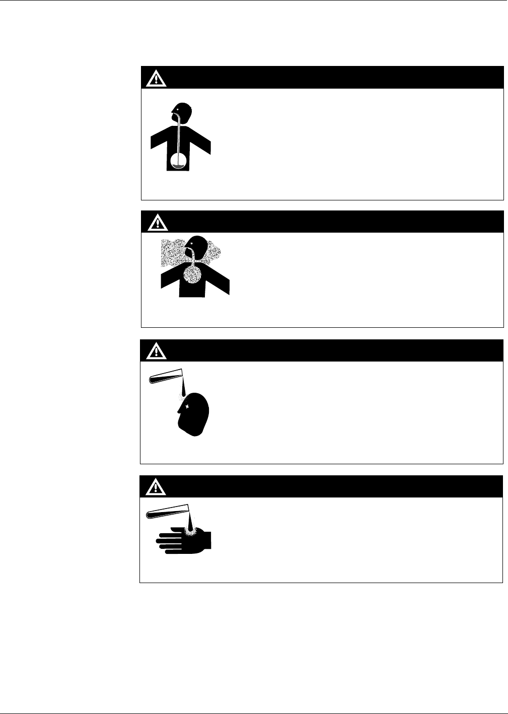
If any gasoline has been inhaled, seek emergency help immediately.
Inhaled gasoline may cause unconsciousness and burns to lips, mouth and lungs.
WARNING
Gasoline spilled on skin may cause burns.
Wash area thoroughly with clean water.
Seek medical advice immediately.
WARNING
MDE-3883 TRIND Retrofit Kits C00011-005 • 10/00 Page 11
Important Safety Information
PRELIMINARY
FCC 11/30
Emergency and First Aid Information
Refer to phone book for emergency phone numbers. If needed, follow first aid instructions as
outlined in American Red Cross Standard First Aid manuals.
Gasoline
Ingestion
Gasoline Vapor
Inhalation
Gasoline spilled in eyes may cause burns to eye tissue.
Irrigate eyes with water for approximately 15 minutes.
Seek medical advice immediately
Gasoline spilled on skin may cause burns.
Wash area thoroughly with clear/water.
Seek medical advice immediately.
Gasoline On
Skin
Gasoline In
Eyes
Gasoline inhaled may cause unconsciousness and burns to lips,
mouth and lungs.
Keep airway open.
Seek medical advice immediately.
WARNING
WARNING
WARNING
WARNING
Gasoline ingested may cause unconsciousness and burns to
internal organs.
Do not induce vomiting.
Keep airway open.
Oxygen may be needed at scene.
Seek medical advice immediately.
Important Safety Information
Page 12 MDE-3883 TRIND Retrofit Kits C00011-005 • 10/00
PRELIMINARY
FCC 11/30
Warning Labels Several types of warning labels appear on Marconi products to inform and remind users of
important safety information. Read, understand and follow these warnings.
Sample Warning Label
The following labels are typical of those you may find on Marconi’s products:
Working Alone It is highly recommended that someone who is capable of rendering first aid be present during
servicing. Be familiar with Cardiopulmonary Resuscitation (CPR) methods if you are working
with or around high voltages. This information is available from the American Red Cross.
Always advise the station personnel about where you will be working, and caution them not to
activate power while you are working on the equipment. Use the OSHA tag out and lock out
procedures discussed later in this section.
Contacting Emergency Personnel
Keep the following emergency phone numbers at hand.
Ambulance:_____________________________________
Fire:___________________________________________
Police:_________________________________________
Poison Control Center:____________________________
Informing Emergency Personnel
Compile the following information for emergency personnel:
•Location of accident (e.g. address, front/back of building, etc.)
•Nature of accident (e.g. possible heart attach, run over by car, burns, etc.)
•Age of victim (e.g. baby, teenager, middle-age, elderly)
•Whether or not victim has received first aid (e.g. stopped bleeding by pressure, etc.)
•Whether or not victim has vomited (e.g. if swallowed or inhaled something, etc.)
IMPORTANT: Oxygen may be needed at scene if gasoline has been ingested or inhaled. Seek
medical advice immediately.

MDE-3883 TRIND Retrofit Kits C00011-005 • 10/00 Page 13
Important Safety Information
PRELIMINARY
FCC 11/30
Other Useful Safety Information
This subsection provides additional safety information.
OSHA Lock-Out and Tag-Out Requirements
OSHA Standard 29 CFR 1910-147 Control of Hazardous Energy Sources (Lock-Out/Tag-Out)
covers ways to avoid personal injury because power was turned on or fuel pressure was applied
unexpectedly while servicing equipment. The rule requires:
(1) Turning off equipment power and fuel under pressure
(2) Use of a locking device (breaker, valve, etc.) or label device with a warning tag.
Station employees and service contractors need to understand and comply with this program
completely to ensure safety while the equipment is down.
Breakaways
Required by NFPA 30A, breakaways are emergency devices designed to retain liquid on both
sides of the breakaway point installed on each hose. Refer to manufacturer’s instructions for
proper installation.
Collection of Fuel in Approved Containers
NFPA 30A, Section 2, requires use of approved containers to collect, transport, and dispose of
fuel. Containers must be specifically designed and labeled for handling hazardous fuels.
Read Material Safety Data Sheets (MSDS)
Before working with any chemicals or fuels in and around a dispensing facility, read the
MSDS pertaining to those chemicals as prescribed in the Occupational Safety and Health
Administration Standard, 29 CFR 1910.1200. Refer to the supplier’s literature.
Replacement Parts
Use only genuine Marconi replacement parts and retrofit kits on your pump/dispenser. Using
parts other than genuine Marconi replacement parts could create a safety hazard and violate
local regulations.
Important Safety Information
Page 14 MDE-3883 TRIND Retrofit Kits C00011-005 • 10/00
PRELIMINARY
FCC 11/30
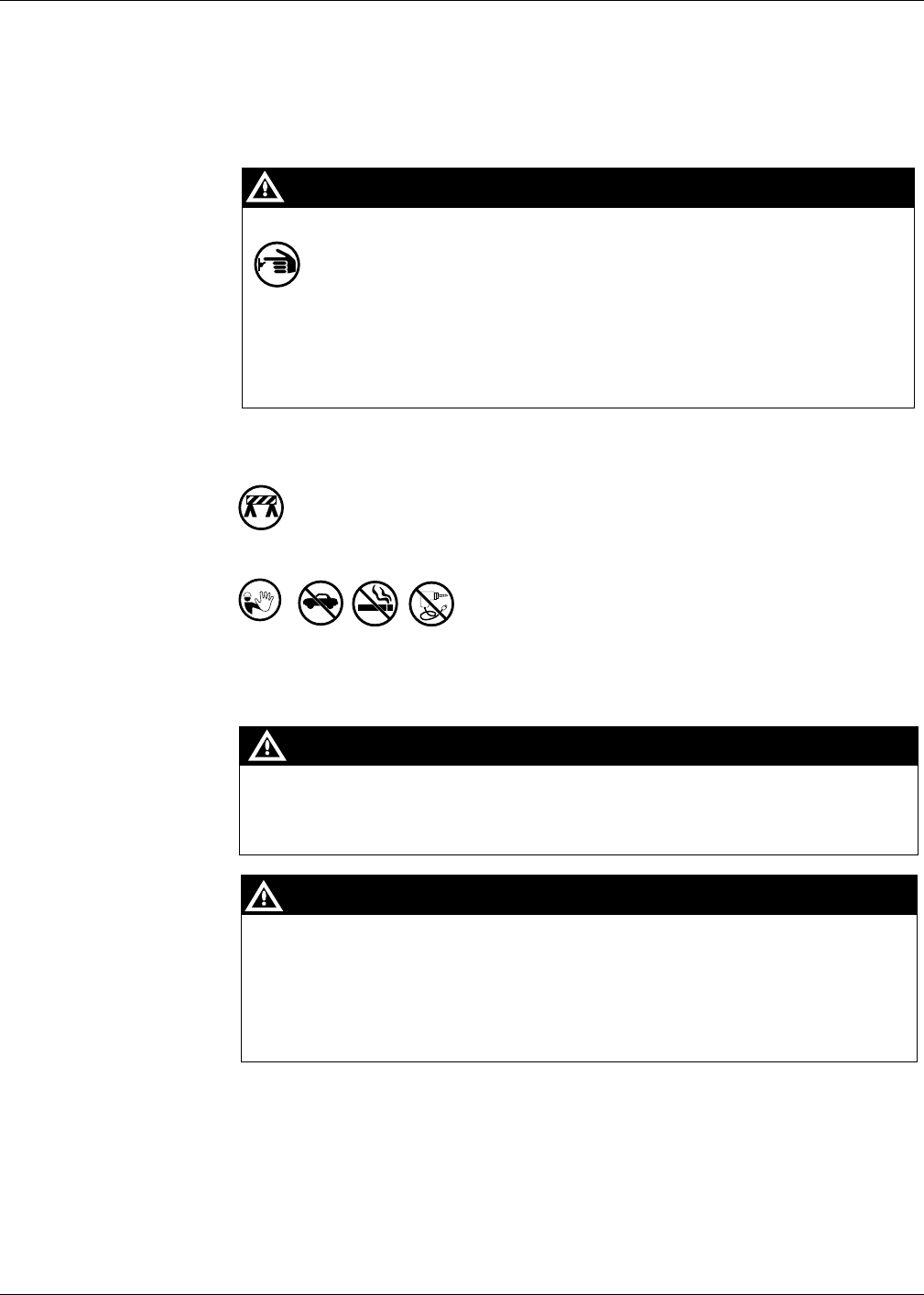
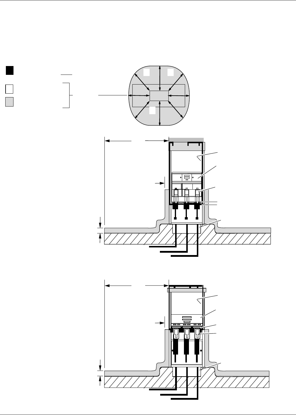
Classifying Hazardous Locations
Any activity that can cause an explosion (e.g., smoking, drilling, etc.) must be
done well outside the vapor area.
The following diagrams are based on NFPA 30A, section 6 and NFPA 70, section
514.
Fuel is present.
(Flammable Liquid)
Class 1 Division 2
(Hazardous Location)
Class 1 Division 1
(Hazardous Location)
Fuel Containing
Components
Vapor Areas
18"
18"
Unclassified location
area within electronics cabinet
above Air Gap.
Class 1 Division 1
within boot area.
Air Gap
20'
Pit box.
20'
20'
20'
Unclassified location
Electronics Head
Vapor Barrier
20'
Pit box.
18"
18"
Vertical Vapor Barrier
Vertical Vapor Barrier
Class 1 Division 1
within boot area.
MPD®-3 Series
with
Vapor Barrier
The
Advantage®
Series with
Air Gap
MDE-3883 TRIND Retrofit Kits C00011-005 • 10/00 Page 15
The Advantage Series Installation
PRELIMINARY
FCC 11/30
The Advantage Series Installation
Preparing for Installation
1Before proceeding read and follow all safety instructions and procedures.
2Open main access doors. Refer to MDE-2531, Pump and Dispenser Start-Up/
Service Manual for access instructions.
3Disconnect and remove existing hardware according to the following:
•For wide frame units disconnect any cables and remove any call or stop
buttons, or door alarm switch hardware from existing right options door. Save
all removed hardware for reassembly.
•For narrow frame units disconnect cables to PPU and main display.
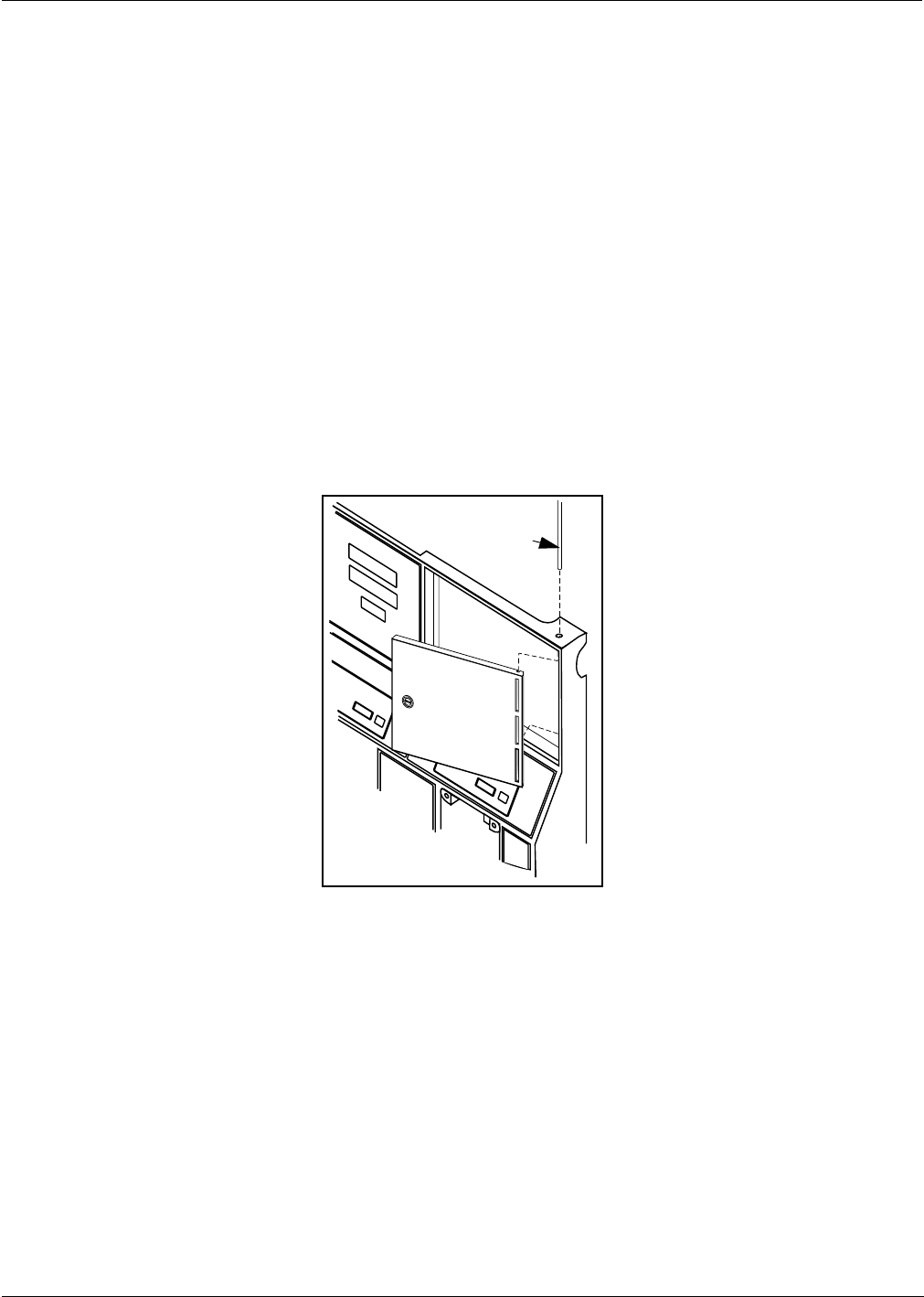
4Remove door mounting pin and right options door.
5If unit has Cash Acceptor, remove door alarm and all hardware from old door and
save.
6Dispose of door. Save pin for reassembly.
S0001719
Pin
The Advantage Series Installation
Page 16 MDE-3883 TRIND Retrofit Kits C00011-005 • 10/00
PRELIMINARY
FCC 11/30
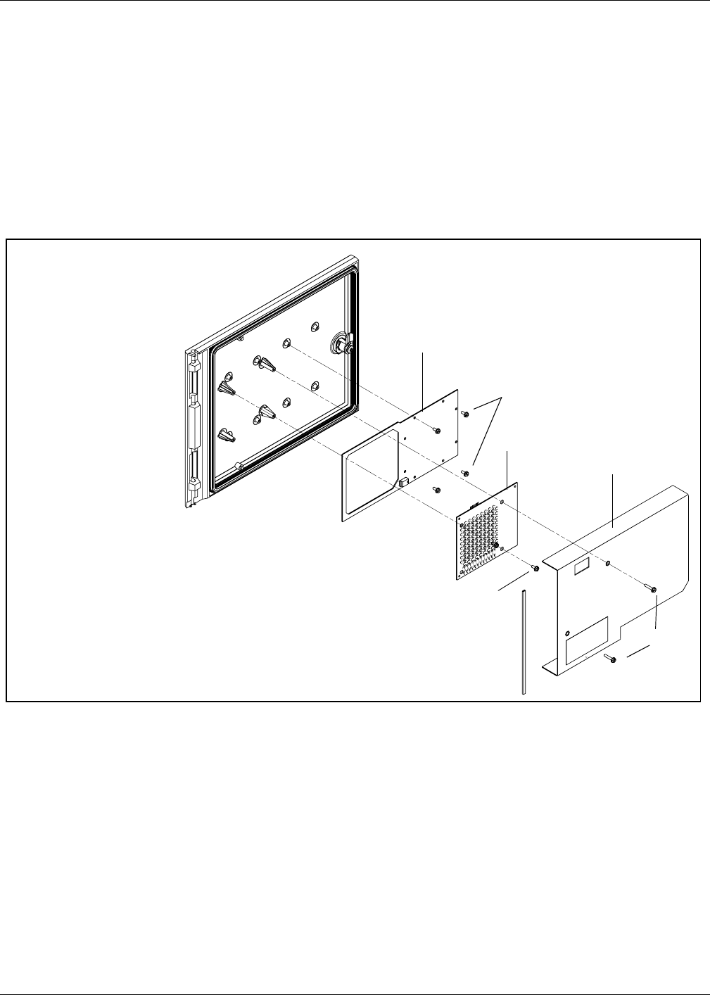
Modifying Right Options Door On Wide Frame Units
Note: T20613-G2 door assemblies are call/stop button ready, and do not need to be
modified. Instructions are provided for modifying T20613-G1 doors for call/
stop button.
For all narrow frame units, or wide frame units without stop or call buttons or
door alarm switches, proceed to “Installing Cables” on page 20. For wide or
narrow frame units without stop or call units but with door alarm, proceed to “Re-
installing Door Alarm Switches” on page 19. For wide frame units with stop or
call button previously installed on right options door, do the following to relocate
hardware to new T20613-G1 options door.
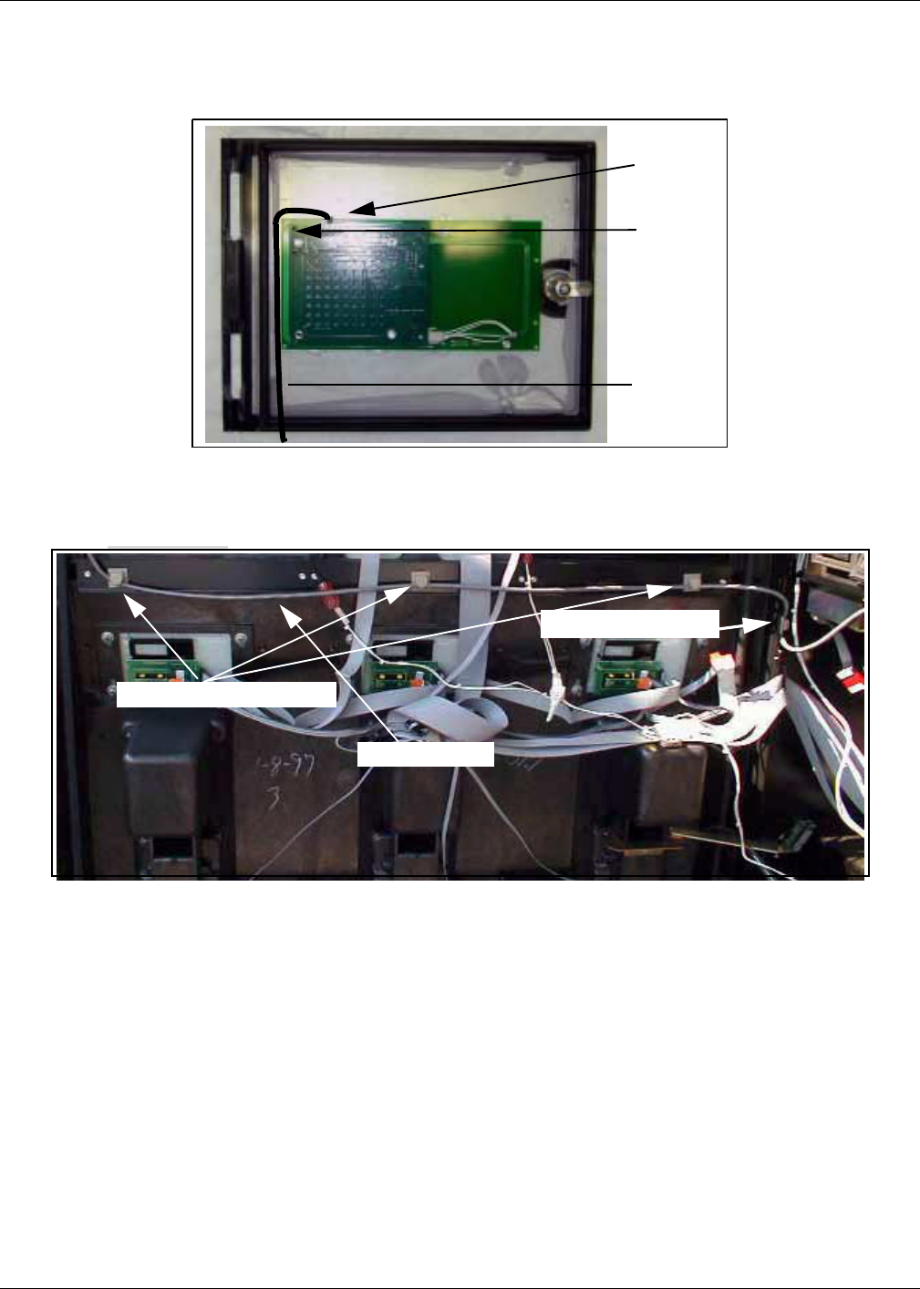
1Remove all hardware from new right options door according to the following steps
and save all parts for reassembly.
•Remove two screws (1) mounting sheet metal antenna shield (2) on rear of
door. Save shield and screws for reassembly.
•Disconnect cable R20522-G1 (not shown) from light/multi-protocol reader
printed circuit board T20601-G1 (3) by disconnecting J181 on cable from P181
on board.
•Remove two standoff-screws (4) holding light/multi-protocol reader board (3),
and remove board. Save for reassembly.
•Remove four screws (5) and antenna board T20524-G1(6). Save for
reassembly.
1
2
3
4
5
6
Wide Frame Right Options Door
T20613-G1
MDE-3883 TRIND Retrofit Kits C00011-005 • 10/00 Page 17
The Advantage Series Installation
PRELIMINARY
FCC 11/30
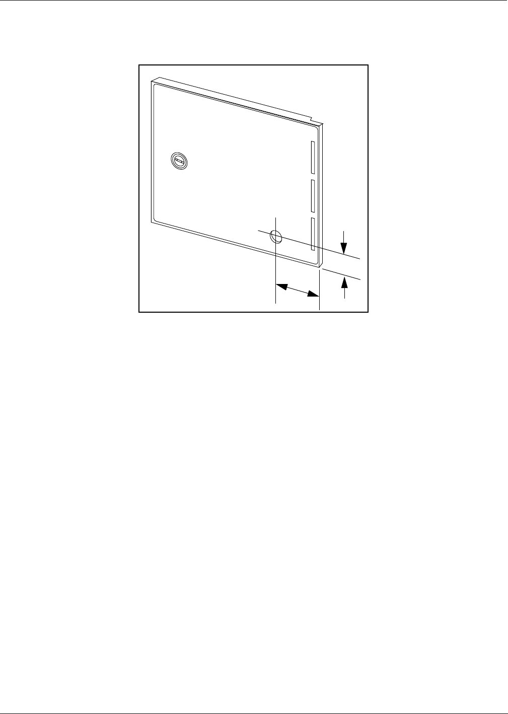
2Use center punch and hammer to mark placement of pump stop or call button
hole on new right options door by measuring from door edges as shown below.
3Away from fuel island, drill a 7/8 inch diameter hole in location illustrated above.
4Remove any burrs around hole with deburring tool or rounded file.
S0001734
1 9/16"
3 3/16"
The Advantage Series Installation
Page 18 MDE-3883 TRIND Retrofit Kits C00011-005 • 10/00
PRELIMINARY
FCC 11/30
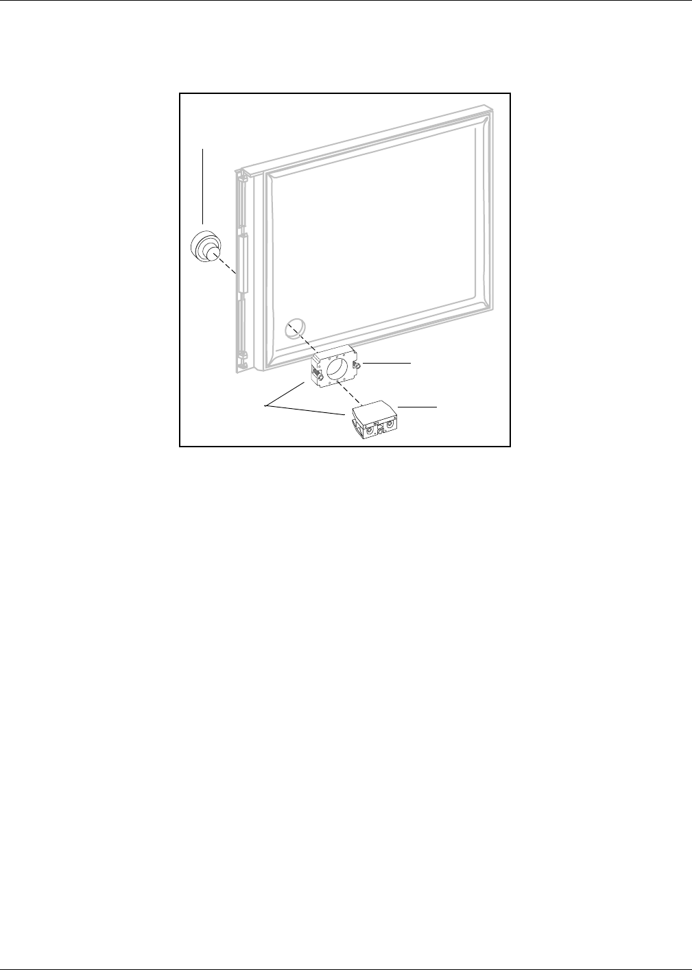
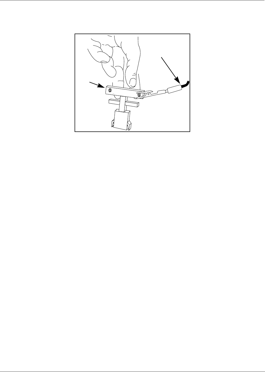
Re-installing Button
1Hold contact base on back of door and align with hole drilled earlier.
2Insert push button from front of door by aligning tabs with slots in base.
3Turn push button 45° clockwise to lock button to base.
4Tighten two screws on base to secure push button and base assembly to door.
Note: Do not overtighten screws.
5Attach contact block to base with center screw if not already installed.
6If unit does not have door alarm, reinstall all new right options door hardware
except sheet metal shield by reversing procedures in Step 1 of “Modifying Right
Options Door On Wide Frame Units” on page 16 and proceed to “Installing
Cables” on page 20. If unit has door alarm, proceed to “Re-installing Door Alarm
Switches” on page 19.
S0001735
Push button
Contact switch
base assembly
Base
Contact
block
MDE-3883 TRIND Retrofit Kits C00011-005 • 10/00 Page 19
The Advantage Series Installation
PRELIMINARY
FCC 11/30
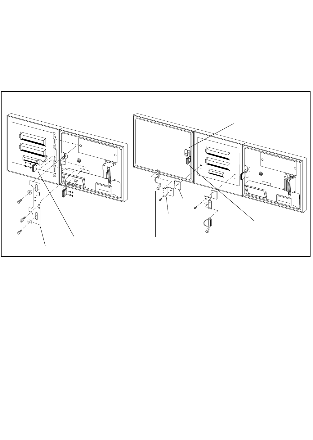
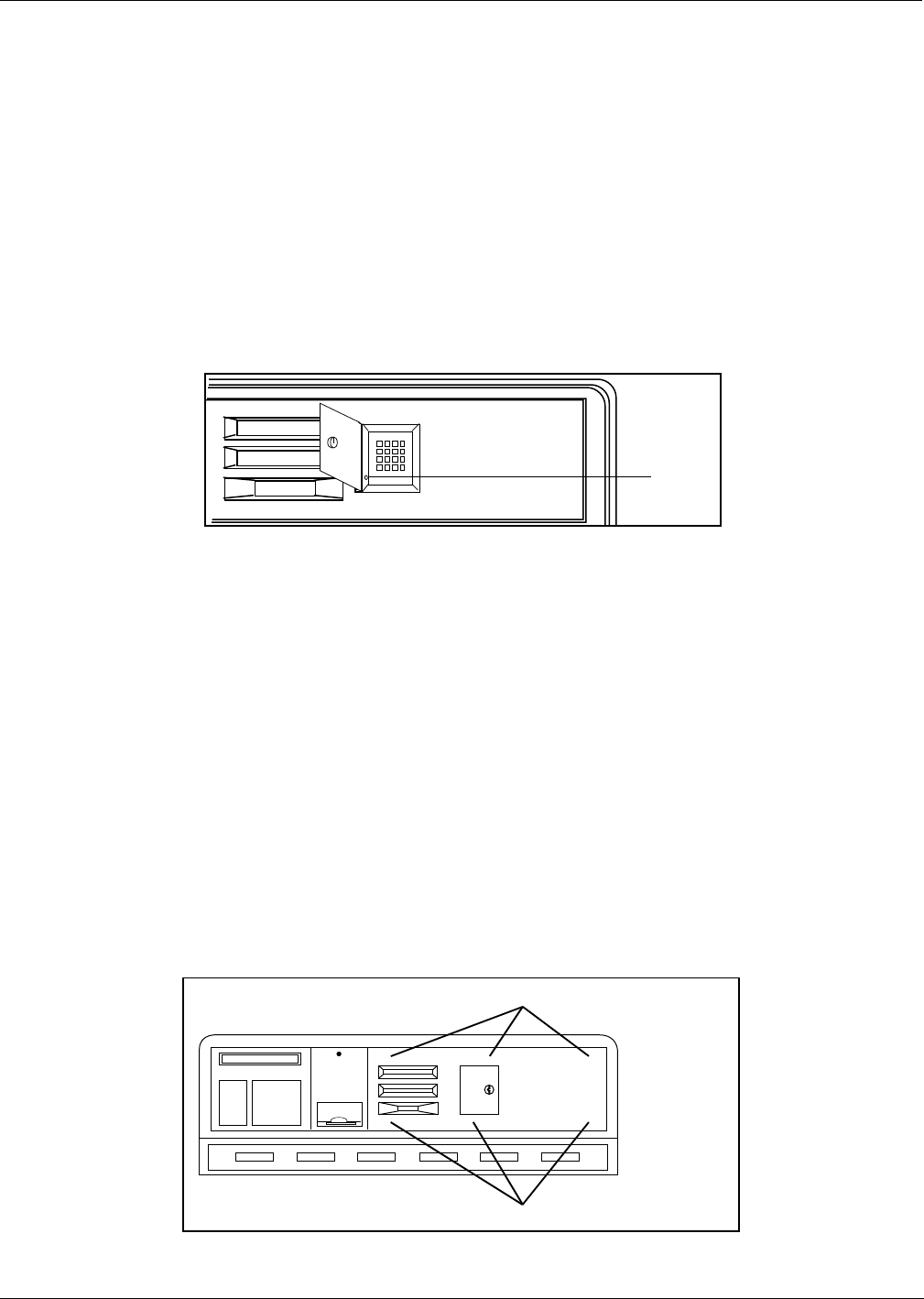
Re-installing Door Alarm Switches
For units with cash acceptors, follow these steps to re-install door alarm
assemblies on TRIND™ right option doors. Refer to diagram on this page for more
information. Perform each step for both ‘A’ and ‘B’ side right option doors.
1Remove lock hardware from new right options door.
2Re-install C-clips removed from old right side option doors on new door.
3Install door alarm assembly to door alarm assembly bracket with screw
previously removed.
4Attach door alarm assembly bracket to display board with screw previously
removed.
Note: Replace the piece of fiberboard between door alarm bracket assembly and
display board.
5Be sure magnet does not touch door alarm door bracket. Slightly move door alarm
door bracket away, if necessary.
6Reinstall all new right options door TRIND hardware except sheet metal cover by
reversing procedures in Step 1 of “Modifying Right Options Door On Wide Frame
Units” on page 16.
S0001736
S0001737
Back view of 36” Unit Option Doors Back view of 48” Unit Option Doors
Door alarm assembly bracket
Door alarm assembly
Right option door
C-clip
Door alarm door bracket
Fiber board
Door alarm
assembly bracket
Door alarm assembly
The Advantage Series Installation
Page 20 MDE-3883 TRIND Retrofit Kits C00011-005 • 10/00
PRELIMINARY
FCC 11/30
Installing Cables
Position kit cables according to the following steps:
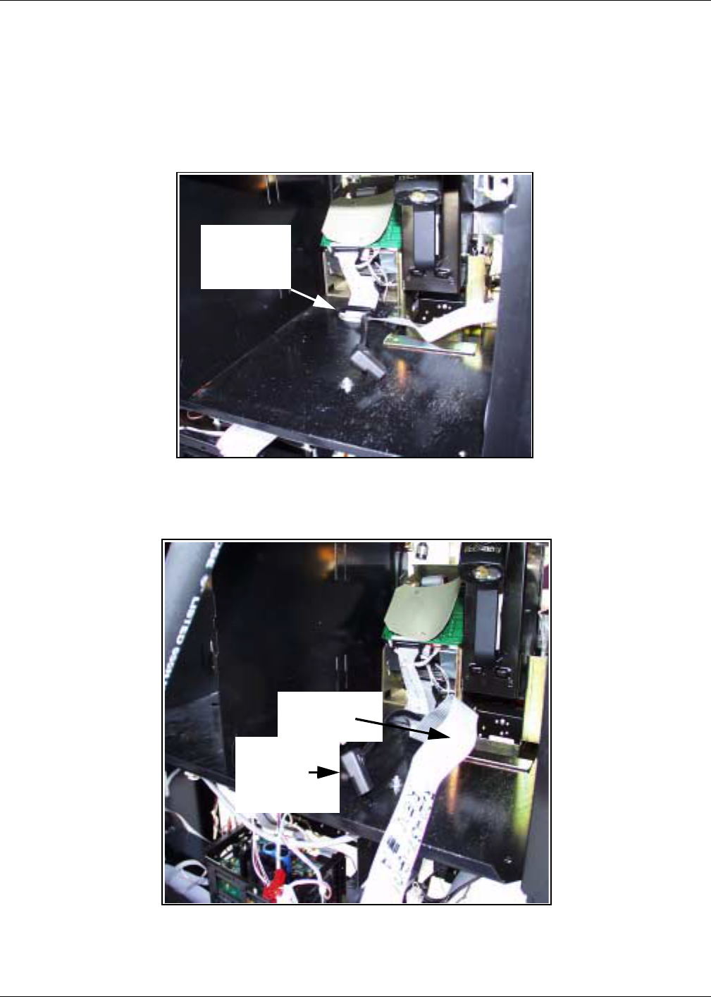
1Carefully pry out printer cable retainer from underside of printer shelf.
2Disconnect printer cable and pull cable out of 2 3/4" round hole from bottom, and
install piece of strip grommet Q10315-01 around perimeter of hole.
3Feed three-prong end of power cable R20580-G1 and connector J250 end of
R20437-G01 ribbon cable up through hole and lay cable ends toward A side.
4Reinstall printer cable and retainer disconnected and removed in step 2.
2 3/4” printer
cable hole
and cable
retainer
R20580-G1
R20437-G01
ribbon cable
MDE-3883 TRIND Retrofit Kits C00011-005 • 10/00 Page 21
The Advantage Series Installation
PRELIMINARY
FCC 11/30
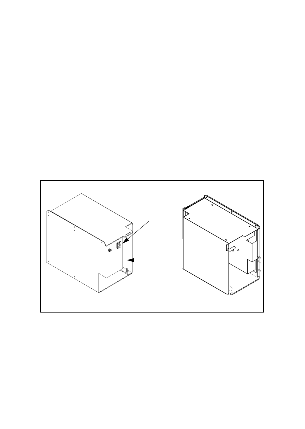
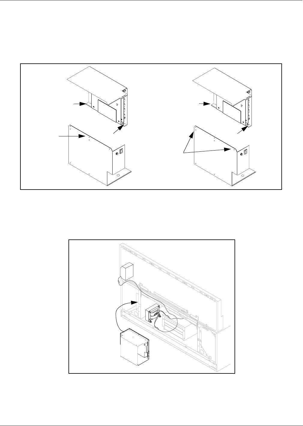
Installing Card Cage
Prepare T20606-G3 card cage for installation.
Note: For more cable connection detail see “Addressing Gateway Board” on
page 35.
1Locate tab at left front top of card cage.
2From B side of unit, turning card cage sideways to unit, feed top and rear of card
cage up and into shelf.
Note: Front of card cage will face B side.
3Position card cage so that tab fits over latch cutout for main door latch to secure
card cage to shelf divider. Note position of two screws protruding from bottom of
card cage:
•For newer units, both screws will pass through holes in printer shelf.
•For older units, holes will not align with holes in shelf. Remove both screws
and save.
4Position rear of card cage on edge of cabinet shelf for easy cable connection.
Note: Do not secure card cage at this time. Connecting cables and setting jump
jacks are easier if card cage can be manipulated by installer.
5Connect three prong female end of power cable R20580-G2 to card cage at location
shown.
6Locate harness attached to card cage containing P1 and P2 connectors.
Note: Cables are already connected to Gateway PCB T20678-G1 at J282A/P282A
and J282B/P282B.
7Feed both harness cables down through hole as shown in illustration in Step 3 of
“Installing Cables” on page 20.
Rear
Connect
R20580-G2
3-prong end
Front
Locate harness
cables (with P1
and P2
connectors) -
feed through
this end
T20606-G3 Card Cage shown: Gateway Board located inside card cage
The Advantage Series Installation
Page 22 MDE-3883 TRIND Retrofit Kits C00011-005 • 10/00
PRELIMINARY
FCC 11/30
Addressing The Advantage Series Units
For The Advantage units it is easier to address Gateway Board before card cage is
installed. Refer to “Addressing Gateway Board” on page 35 for instructions.
Install card cage assembly.
Install card cage by doing the following:
Note: While it is not necessary to remove printer to install card cage you may find
your initial installations easier if this is done. To do so, disconnect two
cables and remove ground connector to A side printer. Remove printer and
printer mounting hardware from unit and save for reinstallation.
1Locate tab at left front top of card cage.
2From B side, turn card cage sideways to unit, feed top and rear of card cage up
and into shelf.
Note: Front of card cage will face B side.
Tab
Clinch
nut
Note:
T20606-G4
card cage
shown
MDE-3883 TRIND Retrofit Kits C00011-005 • 10/00 Page 23
The Advantage Series Installation
PRELIMINARY
FCC 11/30
3Position card cage so that tab fits over latch cutout for main door latch, securing
card cage to shelf divider.
•If two screws on card cage pass through shelf secure from underside of shelf
with two nuts provided in kit.
•If screws were removed, secure card cage from underside of shelf by installing
one screw removed in section “Prepare T20606-G3 card cage for installation.”
on page 21 up through hole in shelf to clinch nut on card cage (see illustration
above). Dispose of second screw and two nuts.
Installing Right Option Door
Install new right options door according to the following steps.
1If sheet metal shield has not been previously removed, using 1/4’’ nut driver, remove sheet
metal shield from back of door. Refer to illustration in “Modifying Right Options Door On
Wide Frame Units” on page 16 for detail. Save cover and hardware.
2Remove key taped to inside of new right options door and save.
3Position new right options door and install with pin removed with old door and
saved.
Note: If unit had stop or call button transferred from old door to new TRIND door,
reconnect stop or call button wires to contact block.
4For narrow frame units, reconnect existing cables to new door PPU and main
display.
Route cables to Right Option Doors
1Connect J182 on one R20773-G2 cable to A Side Light/Microreader PCB at P182, and do the
same for B Side.
Tab locks into shelf divided at latch cut-out
The Advantage Series Installation
Page 24 MDE-3883 TRIND Retrofit Kits C00011-005 • 10/00
PRELIMINARY
FCC 11/30
2Route R20773-G2 cables around board as shown for both wide and narrow frame
units, securing cable to board with tie-wrap.
3Route A side cable R20773-G2 along door with clamps provided with kit until
connector end is fed through clamp inside door. Do the same for B Side cable.
4Route A side card cage harness cable (with P1 connector) to door clamp, and
connect to A Side R20773-G2 cable at P1/J1.
Note: Card cage harness cables were positioned for installation in Step 7 of
“Installing Card Cage” on page 21.
5Route B side harness cable (with P2 connector) through clamps above CRIND
tray to cable clamp inside door, and connect to B Side R20773-G2 cable at P2/J2.
Note: When routing from cabinet to main door, allow sufficient slack in cables to
allow main door to open and close without pulling or crimping cables or
crimping cables when door is closed.
6Reinstall sheet metal cover on door, being careful to avoid crimping cables.
7Proceed to “Connecting Remaining Cables” on page 31.
tie-wrap
R20773-G2
J182
Cable clamps provided with kit
R20773-G2 cable
Cable clamp inside door
MDE-3883 TRIND Retrofit Kits C00011-005 • 10/00 Page 25
MPD-3 Series Installation
PRELIMINARY
FCC 11/30
MPD-3 Series Installation
Removing Faceplate
MPD-3 units have two types of faceplates; slide-in (PMI bezel) and bolt-on (Mack
bezel). Follow directions for the type of faceplate and bezel that applies.
For units with slide-in faceplates on PMI bezels, do the following:
1 Release right side faceplate using keyswitch.
2Open manager keypad door and remove single screw.
3Gently force faceplate up, and slide tip of knife or flat blade screwdriver under
bottom edge of faceplate.
4Pry bottom of faceplate away from unit, until faceplate can be removed from unit.
Dispose of faceplate.
For units with bolt-on faceplates on Mack bezels, do the following:
1Open bezel door and lift until door is latched open.
2Disconnect cable between manager keypad and logic board on bezel door. Discard
cable.
3Locate six sets of nuts and washers securing faceplate to bezel studs, and remove
hardware.
Note: This may require removing mounting hardware from price per unit (PPU)
and CRIND™ logic boards to gain access.
Screw
Stud locations behind faceplate
Stud locations behind faceplate
Faceplate stud locations
on Mack bezels

MPD-3 Series Installation
Page 26 MDE-3883 TRIND Retrofit Kits C00011-005 • 10/00
PRELIMINARY
FCC 11/30
4Remove 6 sets of nuts and washers from faceplate studs and remove faceplate.
Dispose of hardware and faceplate.
5With putty knife, remove keypad door gasket and any adhesive residue.
Providing Cable Access into Main Cabinet
1Open bezel doors on main cabinet.
2Locate indent on rear of door behind 3/4" diameter unopened access point.
3Use 3/4" drill bit to open hole in plastic door from rear of door.
Note:If electric drill is used work must be 20’ from fuel island.
4Use deburring tool or file to round edges of hole.
MDE-3883 TRIND Retrofit Kits C00011-005 • 10/00 Page 27
MPD-3 Series Installation
PRELIMINARY
FCC 11/30
Installing Card Cage Assembly
Install card cage assembly from ‘A’ side of unit, according to the following steps:
1Begin to separate card cage assembly into two pieces by removing one screw on
top and two nuts at bottom, one each front and rear.
2Disconnect cables joining two sides of card cage.
3From ‘A’ side of unit, place bottom section of card cage fuse side first on to left
shelf.
4Reassemble card cage using nuts removed in Step 1 and two (2) tie wraps in place
of screw and reconnect cables.
Remove
screw
Remove Nut
Disassemble Reassemble
(after
installation)
Remove Nut
Replace Nut
Replace Nut
Install tie-wraps
Bottom
section card
cage - fuse
side
Top section
card cage
+
+
+
+
Card cage
installation
location from ‘A’
side

MPD-3 Series Installation
Page 28 MDE-3883 TRIND Retrofit Kits C00011-005 • 10/00
PRELIMINARY
FCC 11/30
5For units with Screened Image Display (SIDs) only, do the following:
Note: If these directions are not followed printed circuit boards will be damaged.
•From ‘B’ side of unit, install screw up through hole under card cage. Align
screw with mounting hole on card cage, but do not fasten.
•Tilt card cage away from screw, and secure screw to shelf by installing two
nuts under card cage.
•Let card cage rest on nuts with screw protruding up through hole in card cage.
Note: This will result in card cage tilting down toward the ‘A’ side.
6For all units, from ‘A’ side of unit, fasten card cage to shelf using 6-32 x 3/8" screw
(Q12083-13) supplied with kit.

MDE-3883 TRIND Retrofit Kits C00011-005 • 10/00 Page 29
MPD-3 Series Installation
PRELIMINARY
FCC 11/30
Installing TRIND™ Faceplate Assembly.
Perform the following steps for each side of unit.
For installing TRIND slide-in faceplates on PMI bezels, do the following:
1Remove new TRIND faceplate assembly from box.
2Peel adhesive backing off round gasket N23881-01. Install gasket adhesive side first to
sheet metal shield on back of faceplate to form seal around hole for cables on faceplate
assembly.
3Feed ends of faceplate cables (with P1/2 connectors) through 3/4" hole on bezel
door drilled in Step 3 of “Providing Cable Access into Main Cabinet” on page 26.
4Follow these directions to install new TRIND faceplate:
•Feed top edge of faceplate in to groove on top of door.
•Gently push bottom of faceplate in until faceplate drops into bottom groove.
•Secure in place with keylock.
5Refer to MDE-2620, Graphics Panel Application for instructions on installing
graphics.
For installing TRIND™ bolt-on (stud type) faceplates, do the following:
1Remove new TRIND faceplate assembly from box.
2Remove existing manager keypad from bezel door, and use putty knife to remove
keypad gasket and adhesive residue from door.
3Replace the door gasket removed in step 2 with adhesive backed gasket Q11659-
01.
4Replace existing keypad and keypad cable with T17549-G1 keypad assembly and
R18163-G1 keypad cable, but do not install keypad on bezel door.
Note:At user’s discretion, new keypad can be placed behind brand panel lighting or
in the well behind the printer door, on either side of printer, provided cable is
run and secured properly and safe access is maintained.
5Remove yellow tape on back of bezel door covering round hole.
6Peel adhesive backing off round gasket N23881-01. Install gasket adhesive side
first to seal around hole on back of bezel door.
7Feed ends of faceplate cables with P1/2 connectors through 3/4" hole on door.
MPD-3 Series Installation
Page 30 MDE-3883 TRIND Retrofit Kits C00011-005 • 10/00
PRELIMINARY
FCC 11/30
8Install 6 split spacers K87404-01 on the faceplate side of the bezel door, in the
mounting holes for the faceplate. See illustration on this page.
9Install faceplate assembly T20616-G2, securing in place from back side of bezel
door using in this order:
•6 adhesive backed gaskets, Q11659-01.
Note: Do not remove paper backing on adhesive side, and install paper side to bezel
door.
•6 flat washers, N16599-01
•6 self-locking nuts, Q10218-04
10 Refer to MDE-2620, Graphics Panel Application for instructions on installing
graphics.
TRIND faceplate
BezelFaceplate
stud
Split spacer Gasket, adhesive
backed with paper left
on and facing bezel
Washer
Nut
MDE-3883 TRIND Retrofit Kits C00011-005 • 10/00 Page 31
Connecting Remaining Cables
PRELIMINARY
FCC 11/30
Connecting Remaining Cables
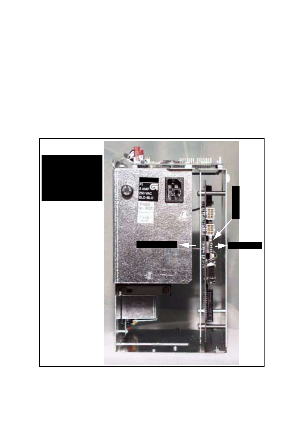
1From A side, pass J250 end of cable R20437-G01 through card cage to B side.
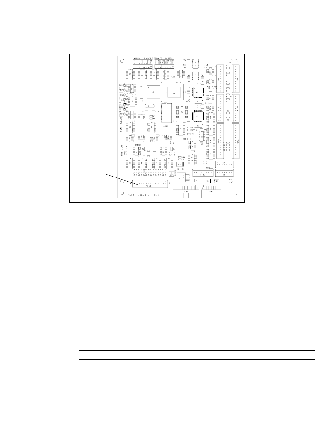
2Connect J250 on ribbon cable R20437-G01 to P250 on Gateway PCB T20678-G1
in card cage (on T20606-G3 card cages) or on top of card cage (T20606-G4 card
cages).
From A side of unit make the following connections:
1On ribbon cable R20437-G01, connect J258A to P258 on A side CRIND Logic Board.
Note: A side of split cable R20437-G01 has red wire.
2On ribbon cable R20437-G01, connect J258B to P258 on B side CRIND Logic
Board.
Connect R20580-G1 power cable according to the following:
Note: Connections are unit specific. Use appropriate connectors to intercept power
by installing R20590-G1 inline. Refer to “Cable Block Diagram” on page 37.
For units with: Do the following:
System cable W02468 Install inline using 15 pin P601 and J601 connectors
System cable T19612 Install inline using 3 pin connectors J601/J708 and P601/P708
P250 on
T20678-G1
PCB
CRIND® BIOS TRIND™ Multi 1 Upgrade
Page 32 MDE-3883 TRIND Retrofit Kits C00011-005 • 10/00
PRELIMINARY
FCC 11/30
CRIND® BIOS TRIND™ Multi 1 Upgrade
Units must have current Z-180 CRIND logic board.
Install the CRIND BIOS TRIND software K93744-XX, one per logic board, on the
T17764-XX CRIND logic board(s) according to the following steps.
Note: A properly grounded electrostatic discharge wrist strap must be worn during
this procedure.
U7
Chip
orientation
notch
T17764-XX
CRIND
logic board
(-G3 shown)
JP1-16
MDE-3883 TRIND Retrofit Kits C00011-005 • 10/00 Page 33
CRIND® BIOS TRIND™ Multi 1 Upgrade
PRELIMINARY
FCC 11/30
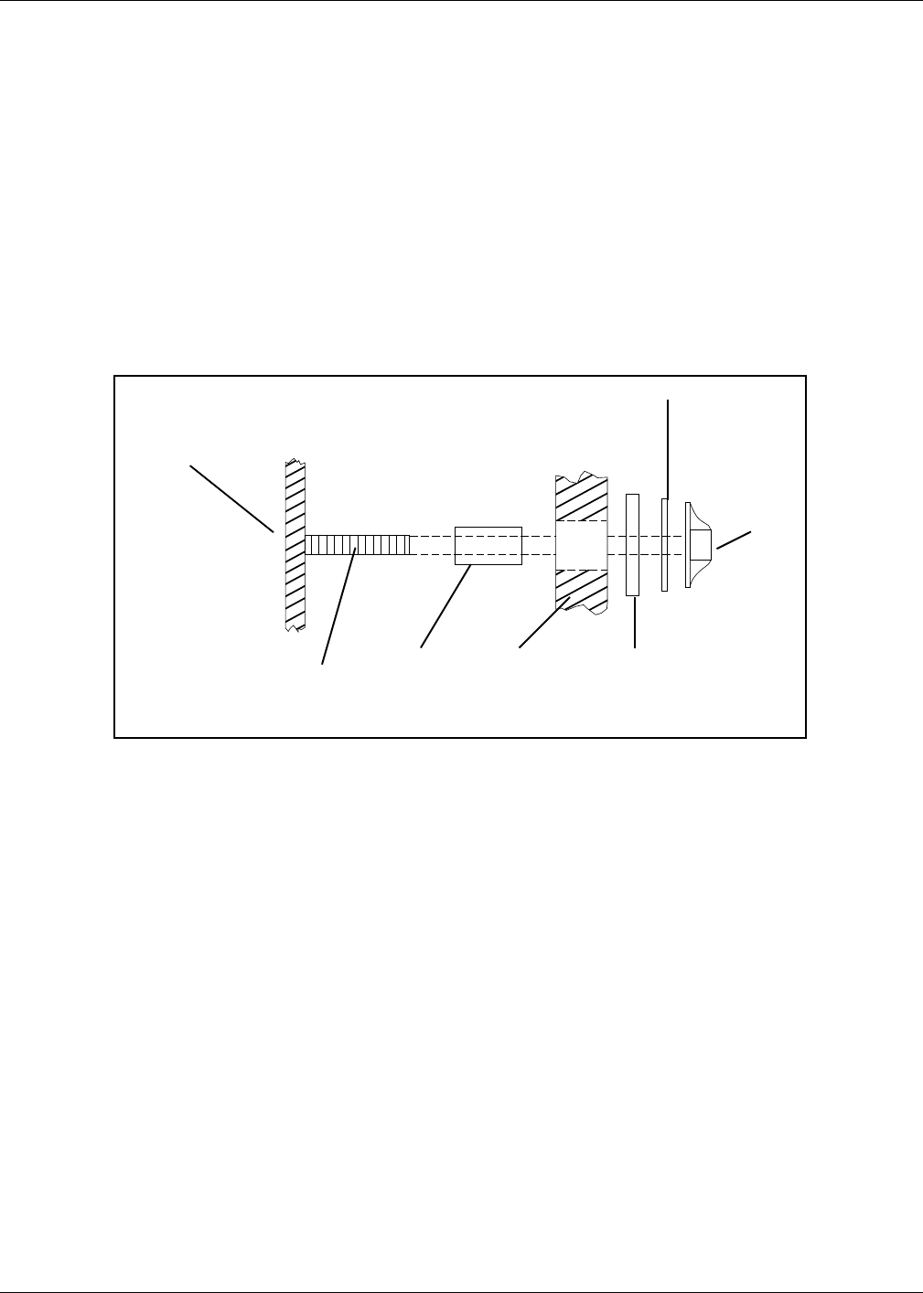
1Locate and remove existing BIOS at U7 on CRIND® logic board T17764-XX using
a grounded chip removal tool.
.
2Install TRIND BIOS K93744-XX (one per logic board) at position U7, orienting
notch on chip with indication mark on board as shown.
3Install jump jack on JP-16 for each side of unit.
Note: Jumper on JP-16 informs the CRIND that a TRIND system is present.
4Restore CRIND tray to operating position.
Chip
removal
tool
Grounding strap
Dispenser Set-Up
Page 34 MDE-3883 TRIND Retrofit Kits C00011-005 • 10/00
PRELIMINARY
FCC 11/30
Dispenser Set-Up
Addressing Dispenser
Each dispenser on the G-Site controller must be addressed differently; no two
dispensers may have the same address. Address is at discretion of the installer.
Follow these steps:
1From A side of unit, locate dip switches on power supply board (PCB) T20314-G1 in card
cage.
2Using switches 2, 3, 4 and 5 address each dispenser according to the following
table:
Note: Switch one in down position is standalone mode selected, used for service
only.
Setting Baud Rate
For major oil company (MOC) TRIND™ installations there is no requirement to
set or change baud rate.
Switch Numbers = Value
1 = Standalone Mode
2 = 1
3 = 2
4 = 4
5 = 8 1
2
3
4
5
Dip switch down Dip switch up
T20606-G4
MDE-3883 TRIND Retrofit Kits C00011-005 • 10/00 Page 35
Dispenser Set-Up
PRELIMINARY
FCC 11/30
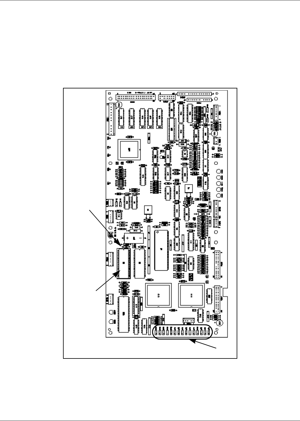
Addressing Gateway Board
Address for TRIND™ must match address on CRIND® logic board. Follow these
steps:
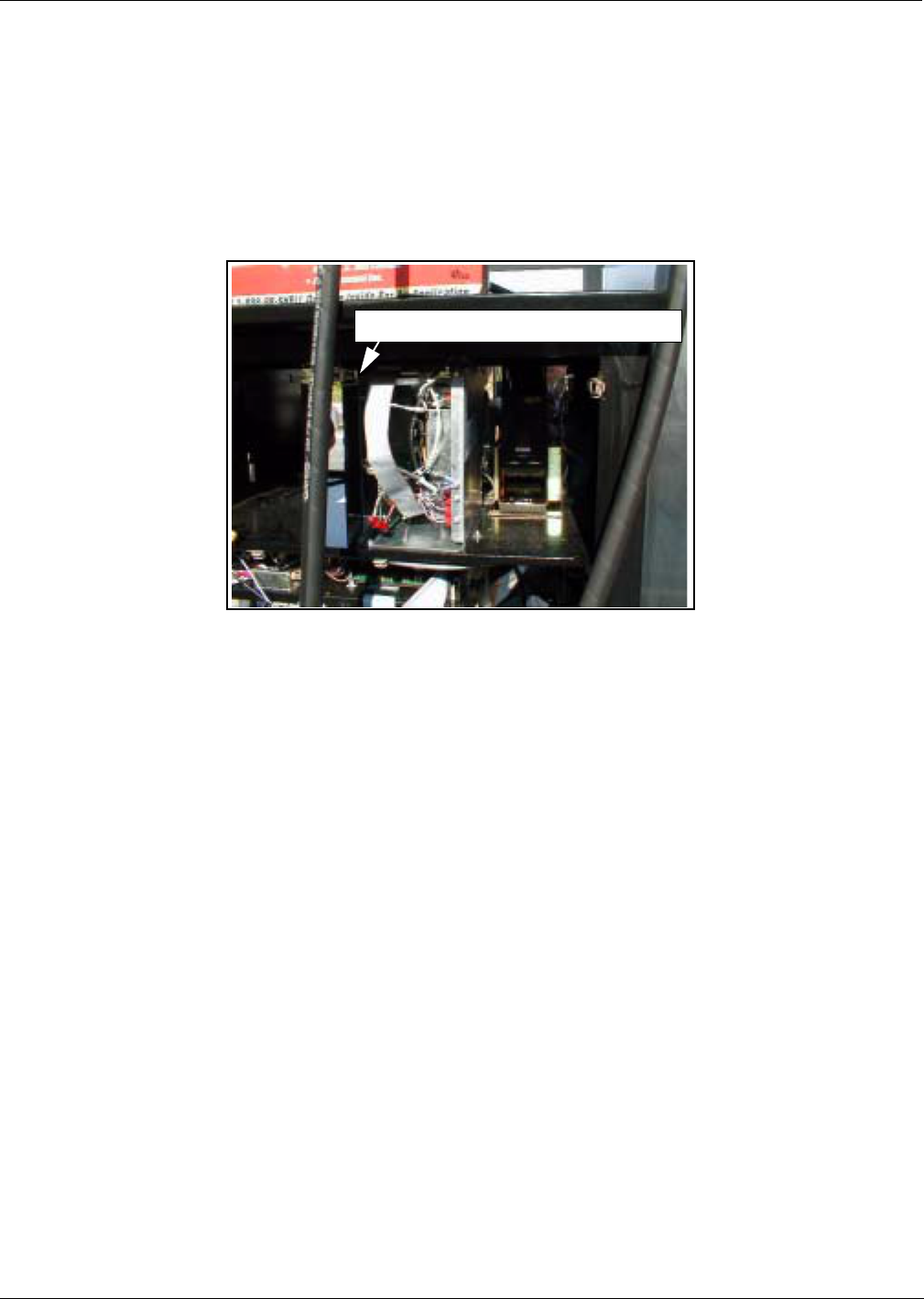
1From A side of unit lower CRIND tray. Refer to MDE-2562 CRIND Service Manual.
2Locate jump jacks on A and B side CRIND logic boards T17764-XX.
3Note position of jump jacks and set jump jacks on Gateway board T20678-G1 to
match address on CRIND logic boards for both A and B sides.
MOC and Generic CRIND Addresses
Address On CRIND Logic Board T17764-XX JP8 JP7 JP6 JP5 JP4
= Address on Gateway Board T20128 ‘A’ Side JP6 JP7 JP8 JP9 JP10
= Address on Gateway Board T20128 ‘B’ Side JP14 JP15 JP16 JP17 JP18
1 IN OUT OUT OUT OUT
2 OUT IN OUT OUT OUT
3 ININOUTOUTOUT
4 OUT OUT IN OUT OUT
5 IN OUT IN OUT OUT
6 OUT IN IN OUT OUT
7 INININOUTOUT
8 OUT OUT OUT IN OUT
9 INOUTOUTINOUT
10 OUT IN OUT IN OUT
11 IN IN OUT IN OUT
12 OUT OUT IN IN OUT
13 INOUTININOUT
14 OUTINININOUT
15 IN IN IN IN OUT
16 OUT OUT OUT OUT IN
17 IN OUT OUT OUT IN
18 OUT IN OUT OUT IN
19 IN IN OUT OUT IN
20 OUT OUT IN OUT IN
21 IN OUT IN OUT IN
22 OUTININOUTIN
23 IN IN IN OUT IN
24 OUT OUT OUT IN IN
25 IN OUT OUT IN IN
26 OUT IN OUT IN IN
27 IN IN OUT IN IN
28 OUT OUT IN IN IN
29 INOUTINININ
30 OUTININININ
31 IN IN IN IN IN
32 OUT OUT OUT OUT OUT
Jump jack locations on Gateway Board
Accessible at upper left
hand corner of front of
T20606-G3 card cage or
on top of T20606-G4 card
cage

Dispenser Set-Up
Page 36 MDE-3883 TRIND Retrofit Kits C00011-005 • 10/00
PRELIMINARY
FCC 11/30
Testing TRIND™
1For The Advantage series units, if printer was removed, replace printer and reconnect two
cables and ground.
2Restore power to unit. Refer to Pump and Dispenser Service Manual MDE-2531.
3Restoring power with new BIOS will Cold Start the CRIND. Refer to CRIND
Service Manual MDE-2562.
Note: Cold Start is required if TRIND equipment is installed or changed.
4Present test tag at option door from a distance of 6’’ or less. Light board should
light and flash sequentially and emit one beep. A screen prompt should appear.
Note: If light does not function properly, check to see if opposite side of unit was
activated, indicating a crossed cable.
5When using test tag, screen will show “Test Confirmed”. In regular operation,
screen will display instructions to begin fueling.
Completing Installation
1Close and secure option and maindoor.
2Install graphics. Refer to MDE-2620 Graphics Installation for The Advantage
Series.
3Peel backing paper off FCC label pate provided in kit.
4Affix FCC label plate to inside frame sheathing on column under existing FCC
label.
5Restore power to unit. Refer to Pump and Dispenser Service Manual MDE-2531.
MDE-3883 TRIND Retrofit Kits C00011-005 • 10/00 Page 37
Cable Block Diagram
PRELIMINARY
FCC 11/30
Cable Block Diagram
Note: Illustration assumes T20606-G3 Card Cage, with wire harness that includes M00507A00X cables. For T20606-G4 Card Cage, a different harness is
used but cables have the same connector ends: P1 for Side 1 and P2 for Side 2 connections to R20773-G2 cables.

Cable Block Diagram
© 2000 Marconi Commerce Systems Inc.
7300 West Friendly Avenue • Post Office Box 22087
Greensboro, North Carolina 27420
Phone (336) 547-5000 • http://www.marconicommerce.com • Printed in the U.S.A.
MDE-3883 TRIND Retrofit Kits C00011-005 • 10/00
PRELIMINARY
FCC 11/30