Gilbarco TCR Card Reader Transmitter User Manual MDE 4770
Gilbarco Inc. Card Reader Transmitter MDE 4770
Gilbarco >
user manual
Preliminary
06/04/08
MDE-4770 Tribrid Card Reader Installation Manual · June 2008 Page 1
Introduction
Purpose This manual provides installation instructions for installing the M07999B001 Tribrid Card
Reader (TCR). The TCR is used in Encore® S EMV units only.
This equipment has been tested and found to comply with the limits pursuant to Part 15
of the Federal Communications Commission (FCC) Rules. These limits are designed
to provide reasonable protection against harmful interference when the equipment is
operated in a commercial environment. This equipment generates, uses and can
radiate radio frequency energy, and if not installed and used in accordance with the
instruction manual, may cause harmful interference to radio communications.
Operation of this equipment in a residential area is likely to cause harmful interference
in which case the user will be required to correct the interference at his own expense.
Changes or modifications not expressly approved by the manufacturer could void the
user’s authority to operate this equipment.
The long term characteristics or the possible physiological effects of radio frequency
electromagnetic fields have not been investigated by Underwriters’ Laboratories, Inc.
(UL®).
IMPORTANT INFORMATION
Table of Contents
Topic Page
Introduction 1
Important Safety Information 4
Installation of the TCR 6
•Installing the M07999B001 TCR in an Encore S EMV Unit
(without Contactless Card Reader Option)
6
•Installing the M07999B001 TCR in an Encore S EMV Unit (with
Contactless Card Reader Option)
12
Required Reading
Before installing the Card Reader, the installer must read, understand, and follow:
• This manual
• NFPA 30A, The Automotive and Marine Service Station Code
• NFPA 70, The National Electric Code
• Applicable federal, state, and local codes and regulations
Failure to do so may adversely affect the safe use and operation of the equipment.
Note: This installation must be performed by a Gilbarco® Authorized Service Contractor
(ASC) to ensure warranty.
MDE-4770
Tribrid Card Reader Installation Manual
June 2008

Preliminary
Introduction
Page 2 MDE-4770 Tribrid Card Reader Installation Manual · June 2008
Required Tools
The following tools are required to install the TCR:
• Isopropyl alcohol (END-1082)
• Nut drivers, 1/4-inch, 8 mm, 3/8-inch, 9/32-inch socket with long extension
• Putty knife
• Gilbarco Diagnostic card
• CSC test card
• Ratchet set, standard
• Screwdrivers, flat blade and cross tip
• Static guard wrist strap
Parts Lists The following table provides the parts included in the TCR Kit.
Item Description Part Number Quantity
1Reader, Secure Tribrid M07999B001 1
2Cable, TCR/SP Interface M07702A006 1
3Cable, Encrypted Card M07709A001 1
4Nut, Metric, Flange M00414B005 1
5Bracket, Card Reader M07574B001 1
6Gasket, Card Reader M00682B001 1
7Screw Sel TP Hex HD 6-20X Q11677-26 2
8Assembly, Contactless
Antenna
M08285A001 1
9Cable, Antenna Encrypted M07703A001 1
10 Card, Card Reader Cleaning Q11482 1
Related Documents
Document
Number Title GOLD Library
MDE-2562 CRIND Service Manual CRIND and TRIND®
MDE-3804 Encore and Eclipse Series Start-Up/Service Manual Encore and Eclipse®
MDE-3893 Encore/Eclipse Owners Manual Encore and Eclipse
MDE-4516 Encore S Series Owner's Manual Encore and Eclipse
MDE-4625 Graphics Panel Application and Repair Encore and Eclipse
PT-1736 CRIND Illustrated Parts Manual Parts Manual
PT-1936 Encore Series Pump and Dispenser Illustrated Parts Manual Parts Manual

Preliminary
MDE-4770 Tribrid Card Reader Installation Manual · June 2008 Page 3
Introduction
Abbreviations and Acronyms
Term Description
ADA American Disabilities Act
CRIND Card Reader in Dispenser
CSC Contactless Smart Card
EMV Chip Cards Euro Plus/Mastercard®/Visa® Chip Cards
ESD Electrostatic Discharge
PCA Printed Circuit Assembly
POS Point of Sale
RF Radio Frequency
TCR Tribrid Card Reader
TRIND Transmitter/Receiver in Dispenser
Preliminary
Important Safety Information
Page 4 MDE-4770 Tribrid Card Reader Installation Manual · June 2008
Important Safety Information
This section introduces the hazards and safety precautions
associated with installing, inspecting, maintaining or servicing
this product. Before performing any task on this product, read
this safety information and the applicable sections in this
manual, where additional hazards and safety precautions for
your task will be found. Fire, explosion, electrical shock or
pressure release could occur and cause death or serious
injury, if these safe service procedures are not followed.
Preliminary Precautions
You are working in a potentially dangerous environment of
flammable fuels, vapors, and high voltage or pressures. Only
trained or authorized individuals knowledgeable in the related
procedures should install, inspect, maintain or service this
equipment.
Emergency Total Electrical Shut-Off
The first and most important information you must know is
how to stop all fuel flow to the pump/dispenser and island.
Locate the switch or circuit breakers that shut off all power to
all fueling equipment, dispensing devices, and Submerged
Turbine Pumps (STPs).
Total Electrical Shut-Off Before Access
Any procedure that requires access to electrical components
or the electronics of the dispenser requires total electrical
shut off of that unit. Understand the function and location of
this switch or circuit breaker before inspecting, installing,
maintaining, or servicing Gilbarco equipment.
Evacuating, Barricading and Shutting Off
Any procedure that requires access to the pump/dispenser or
STPs requires the following actions:
• An evacuation of all unauthorized persons and vehicles
from the work area
• Use of safety tape, cones or barricades at the affected
unit (s)
• A total electrical shut-off of the affected unit (s)
Read the Manual
Read, understand and follow this manual and any other
labels or related materials supplied with this equipment. If you
do not understand a procedure, call a Gilbarco Authorized
Service Contractor or call the Gilbarco Support Center at
1-800-800-7498. It is imperative to your safety and the safety
of others to understand the procedures before beginning
work.
Follow the Regulations
Applicable information is available in National Fire Protection
Association (NFPA) 30A; Code for Motor Fuel Dispensing
Facilities and Repair Garages, NFPA 70; National Electrical
Code (NEC), Occupational Safety and Hazard Association
(OSHA) regulations and federal, state, and local codes. All
these regulations must be followed. Failure to install, inspect,
maintain or service this equipment in accordance with these
codes, regulations and standards may lead to legal citations
with penalties or affect the safe use and operation of the
equipment.
Replacement Parts
Use only genuine Gilbarco replacement parts and retrofit kits
on your pump/dispenser. Using parts other than genuine
Gilbarco replacement parts could create a safety hazard and
violate local regulations.
Safety Symbols and Warning Words
This section provides important information about warning
symbols and boxes.
Alert Symbol
This safety alert symbol is used in this manual and
on warning labels to alert you to a precaution which must be
followed to prevent potential personal safety hazards. Obey
safety directives that follow this symbol to avoid possible
injury or death.
Signal Words
These signal words used in this manual and on warning
labels tell you the seriousness of particular safety hazards.
The precautions below must be followed to prevent death,
injury or damage to the equipment:
DANGER: Alerts you to a hazard or unsafe practice
which will result in death or serious injury.
WARNING: Alerts you to a hazard or unsafe practice
that could result in death or serious injury.
CAUTION with Alert symbol: Designates a hazard or
unsafe practice which may result in minor injury.
CAUTION without Alert symbol: Designates a hazard
or unsafe practice which may result in property or
equipment damage.
Working With Fuels and Electrical Energy
Prevent Explosions and Fires
Fuels and their vapors will explode or burn, if ignited. Spilled
or leaking fuels cause vapors. Even filling customer tanks will
cause potentially dangerous vapors in the vicinity of the
dispenser or island.
The EMERGENCY STOP, ALL STOP, and
PUMP STOP buttons at the cashier’s station
WILL NOT shut off electrical power to the pump/
dispenser. This means that even if you activate
these stops, fuel may continue to flow
uncontrolled.
You must use the TOTAL ELECTRICAL SHUT-
OFF in the case of an emergency and not the
console’s ALL STOP and PUMP STOP or
similar keys.
!
WARNING
!
!
!
!
Preliminary
MDE-4770 Tribrid Card Reader Installation Manual · June 2008 Page 5
Important Safety Information
No Open Fire
Open flames from matches, lighters, welding
torches or other sources can ignite fuels and their vapors.
No Sparks - No Smoking
Sparks from starting vehicles, starting or using power tools,
burning cigarettes, cigars or pipes can also ignite fuels and
their vapors. Static electricity, including an electrostatic
charge on your body, can cause a spark sufficient to ignite
fuel vapors. Every time you get out of a vehicle, touch the
metal of your vehicle, to discharge any electrostatic charge
before you approach the dispenser island.
Working Alone
It is highly recommended that someone who is capable of
rendering first aid be present during servicing. Familiarize
yourself with Cardiopulmonary Resuscitation (CPR) methods,
if you work with or around high voltages. This information is
available from the American Red Cross. Always advise the
station personnel about where you will be working, and
caution them not to activate power while you are working on
the equipment. Use the OSHA Lockout/ Tagout procedures. If
you are not familiar with this requirement, refer to this
information in the service manual and OSHA documentation.
Working With Electricity Safely
Ensure that you use safe and established practices in
working with electrical devices. Poorly wired devices may
cause a fire, explosion or electrical shock. Ensure that
grounding connections are properly made. Take care that
sealing devices and compounds are in place. Ensure that you
do not pinch wires when replacing covers. Follow OSHA
Lockout/Tagout requirements. Station employees and service
contractors need to understand and comply with this program
completely to ensure safety while the equipment is down.
Hazardous Materials
Some materials present inside electronic enclosures may
present a health hazard if not handled correctly. Ensure that
you clean hands after handling equipment. Do not place any
equipment in the mouth.
In an Emergency
Inform Emergency Personnel
Compile the following information and inform emergency
personnel:
• Location of accident (for example, address, front/back of
building, and so on)
• Nature of accident (for example, possible heart attack, run
over by car, burns, and so on)
• Age of victim (for example, baby, teenager, middle-age,
elderly)
• Whether or not victim has received first aid (for example,
stopped bleeding by pressure, and so on)
• Whether or not a victim has vomited (for example, if
swallowed or inhaled something, and so on)
IMPORTANT: Oxygen may be needed at scene if gasoline
has been ingested or inhaled. Seek medical advice
immediately.
Lockout/Tagout
Lockout/Tagout covers servicing and maintenance of
machines and equipment in which the unexpected
energization or start-up of the machine(s) or equipment or
release of stored energy could cause injury to employees or
personnel. Lockout/Tagout applies to all mechanical,
hydraulic, chemical or other energy, but does not cover
electrical hazards. Subpart S of 29 CFR Part 1910 - Electrical
Hazards, 29 CFR Part 1910.333 contains specific Lockout/
Tagout provision for electrical hazards.
The pump/dispenser contains a chemical known to the
State of California to cause cancer.
WARNING
!
The pump/dispenser contains a chemical known to the
State of California to cause birth defects or other
reproductive harm.
WARNING
!
Gasoline ingested may cause unconsciousness
and burns to internal organs.
Do not induce vomiting.
Keep airway open.
Oxygen may be needed at scene.
Seek medical advice immediately.
WARNING
!
Gasoline inhaled may cause unconsciousness
and burns to lips, mouth and lungs.
Keep airway open.
Seek medical advice immediately.
WARNING
!
Gasoline spilled in eyes may cause burns to eye
tissue.
Irrigate eyes with water for approximately 15
minutes.
Seek medical advice immediately.
!
WARNING
!
Gasoline spilled on skin may cause burns.
Wash area thoroughly with clear water.
Seek medical advice immediately.
WARNING
!

Preliminary
Installation of the TCR
Page 6 MDE-4770 Tribrid Card Reader Installation Manual · June 2008
Installation of the TCR
Installing the M07999B001 TCR in an Encore S EMV Unit (without
Contactless Card Reader Option)
Removing the Existing Card Reader
To remove the existing Card Reader, proceed as follows:
Note: Read all instructions before beginning and observe all safety precautions.
1Obtain an approval from the store manager or responsible personnel to remove the unit from
service.
2Remove AC power to the unit using the station circuit breaker. Refer to MDE-3893 Encore/
Eclipse Owners Manual for details.
3Remove the lower hydraulics panel. The main door has a lower latch underneath the lower left
main door corner. Open this latch. Locate the upper main door lock. Insert the main door key
and open the main door.
4Repeat step 3 for Side 2 of the unit.
5Disconnect the cable harness or ribbon cable connection from the Card Reader (see Figure 1
on page 7).
6Remove the ESD Ground Connection cable from the current Card Reader (if it has one).
7Use a 1/4 inch nut driver or 1/4 inch ratchet and socket to remove the two Hex head screws
(see Figure 1 on page 7) that secure the Card Reader bracket (see Figure 1 on page 7) and the
Card Reader to the option door. Dispose of the Card Reader and bracket, unless you want to
keep the Card Reader as a used spare part.
Note: Make a note of the Card Reader’s gasket orientation. This information will be useful
when you install the new Card Reader gasket (M00682B001) and bracket
(M07574B001). Also, ensure that the option door has been cleaned with isopropyl
alcohol and a clean cloth prior to installing the new Card Reader gasket
(M00682B001).
8Remove the old Card Reader gasket from the option door. Use a putty knife, if required.

Preliminary
MDE-4770 Tribrid Card Reader Installation Manual · June 2008 Page 7
Installation of the TCR
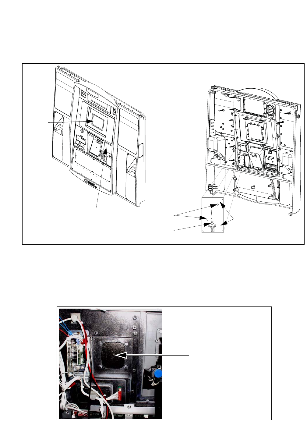
Figure 1: Rear View of the Encore S Main Door with Card Reader
Cable
Harness
Connection
Fastener
Fastener
Installing the Encore TCR Assembly
To install this assembly, proceed as follows:
1Remove the adhesive backing from the Card Reader gasket (M00682B001) and place the
gasket over the Card Reader opening from the inside of the open main door.
A properly grounded ESD wrist strap must be worn when performing step 2. Failure to
use electrostatic precautions may damage electronic components and void warranty.
CAUTION
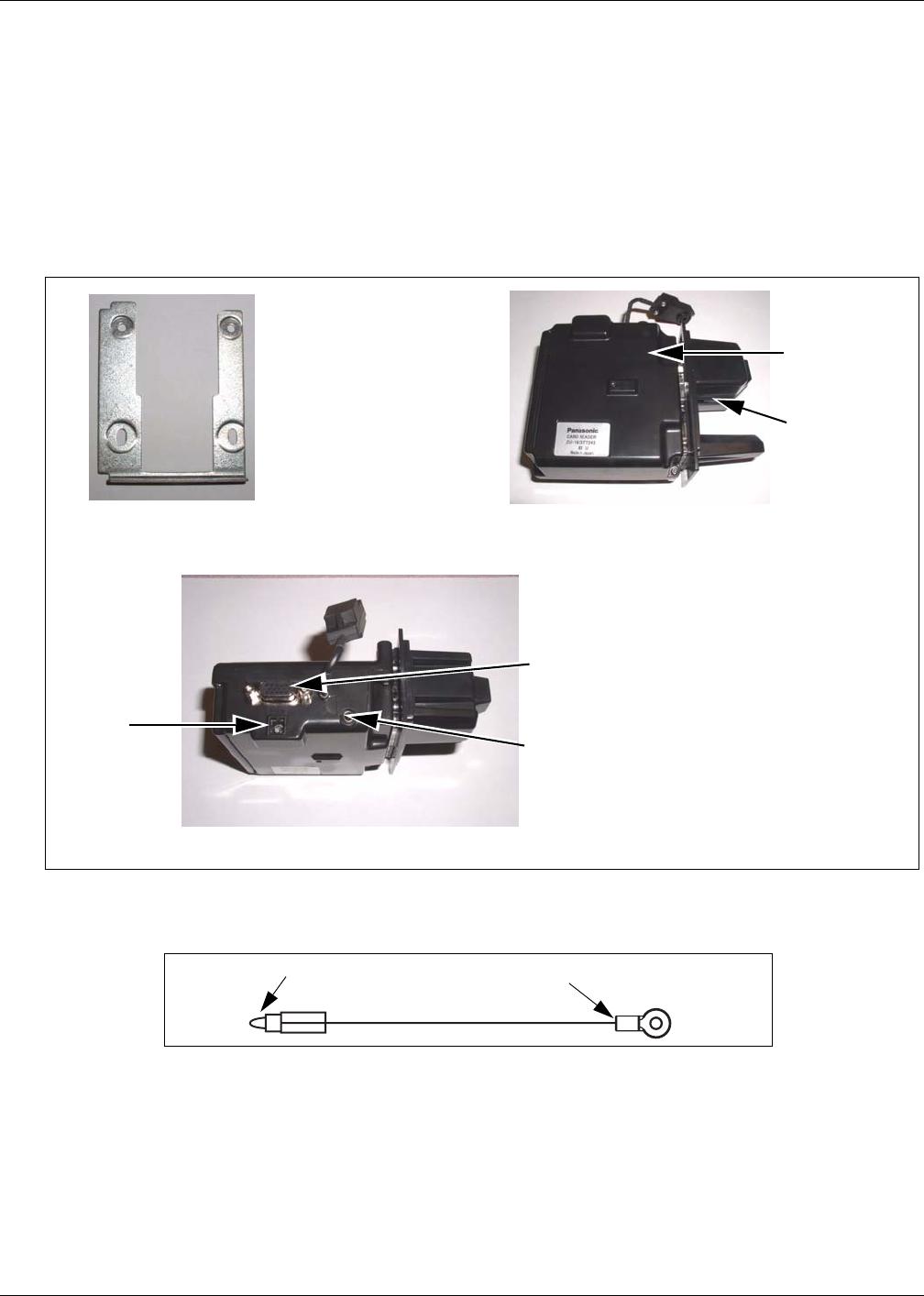
2Obtain the TCR assembly (M07999B001) (see Figure 2 on page 8) from the kit.
3Remove the 6-pin power/data cable (M07702A006) from the TCR.
4Install the ESD ground cable on the new Card Reader before securing it to the main door.
Insert the connector end of the ESD Ground cable (M07709A001) (see Figure 3 on page 8) to
the ESD Ground Connection (see Figure 2 on page 8) on the Card Reader.
Preliminary
Installation of the TCR
Page 8 MDE-4770 Tribrid Card Reader Installation Manual · June 2008
5From the rear of the main door, position the Card Reader and then the Card Reader bracket on
the door, such that the Card Reader slot (see Figure 2) is positioned on the top. Loosely secure
the Card Reader bracket and Card Reader to the main door using the two Q11677-26 screws
(provided in the kit) in the top and bottom two holes (looking from the back of the Card
Reader).
Note: While installing the Card Reader bracket onto the Card Reader, the lip on the bottom of
the bracket should face away from you.
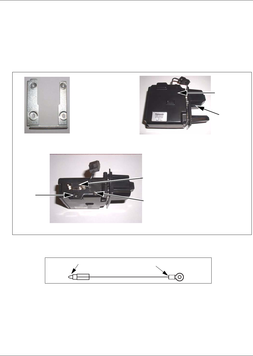
Figure 2: TCR Assembly and Encore S EMV Bracket
Encore S TCR Bracket
(M07574B001) Encore S EMV TCR Assembly (M07999B001) - Front View
Encore S EMV TCR Assembly (M07999B001) - Top View
Printed Circuit
Card (Inside)
Power/Data Connector
Card Reader
Slot
ESD Ground Connection
Antenna
Connector
Figure 3: Encore/Eclipse ESD Ground Cable (M07709A001)
Ring Terminal
Connector
6Align the Card Reader and bracket. Securely tighten the two mounting screws (Q11677-26).
Preliminary
MDE-4770 Tribrid Card Reader Installation Manual · June 2008 Page 9
Installation of the TCR
7Reconnect the 6-pin power/data cable (M07702A006) to the 6-pin power/data connector (see
Figure 2 on page 8) on the TCR.
Note: Tie-wrap the loose end of the cable to ensure that it does not interfere with the other
wires.
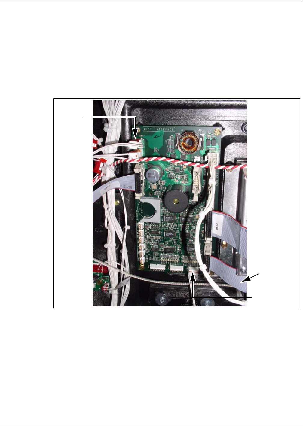
8Connect the appropriate end of M07702A006 to P205 and P206 on the Serial Interface PCB
(M07793A001) (see Figure 4).
Figure 4: Connection of the Cable from the Card Reader to P205 and P206 on the Serial
Interface PCB (M07793A001)
TCR Data Cable
Connection to
Serial Interface
Board
P206
(Power to TCR)
P205
(Data Cable to TCR)

Preliminary
Installation of the TCR
Page 10 MDE-4770 Tribrid Card Reader Installation Manual · June 2008
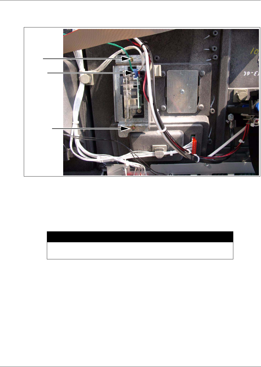
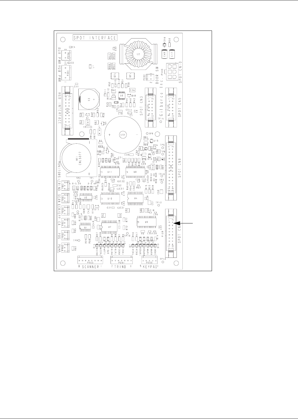
Figure 5: Serial Interface PCB (M07793A001)
P109
9Locate the ground ring terminal on the lower portion of the EMV CRIND display mounting
bracket and remove the screw that secures the ground connection. Retain the screw for
reinstallation.
10 Connect the ring terminal (see Figure 3 on page 8) of the ESD Ground cable (M07709A001)
to the EMV CRIND display mounting bracket ground connection. Secure the connection with
the screw and lock washer that was removed in step 9.
11 Ensure that all ground cables are secured to the unit with sufficient slack to prevent cable pulls
and pinching.
Note: A cable from P109 on M07793A001 connects to the Card Reader connection on EMV
CRIND display (see Figure 5).

Preliminary
MDE-4770 Tribrid Card Reader Installation Manual · June 2008 Page 11
Installation of the TCR
Commissioning the Dispenser/Updating CRIND Software
For EMV units, after installing the TCR, you will have to commission the dispenser. At this
point, you may also update the EMV CRIND software using the SPOTUpdate tool. For
detailed instructions on how to commission the dispenser and update the EMV CRIND
software, refer to MDE-4771 EMV CRIND Start-up/Service Manual.
Completing the Installation for Encore S EMV Units (without Contactless
Card Reader Option)
To complete the installation, proceed as follows:
1Close and secure the main doors using the security latch and the main door lock. Reinstall and
lock the lower panel door.
2Apply the appropriate graphic logos. Refer to MDE-4625 Graphics Panel Application and
Repair for graphic application instructions.
Note: Graphic logos are order entry items.

Preliminary
Installation of the TCR
Page 12 MDE-4770 Tribrid Card Reader Installation Manual · June 2008
Installing the M07999B001 TCR in an Encore S EMV Unit (with Contactless
Card Reader Option)
Removing the Existing Card Reader
To remove the existing Card Reader, proceed as follows:
Note: Read all instructions before beginning and observe all safety precautions.
1Obtain an approval from the store manager or responsible personnel to remove the unit from
service.
2Remove AC power to the unit using the station circuit breaker. Refer to MDE-3893 Encore/
Eclipse Owners Manual for details.
3Remove the lower hydraulics panel. The main door has a lower latch underneath the lower left
main door corner. Open this latch. Locate the upper main door lock. Insert the main door key
and open the main door.
4Repeat step 3 for Side 2 of the unit.
5Disconnect the cable harness or ribbon cable connection from the Card Reader (see Figure 6
on page 13).
6Remove the ESD Ground Connection cable from the current Card Reader (if it has one).
7Use a 1/4 inch nut driver or 1/4 inch ratchet and socket to remove the two Hex head screws
(see Figure 6 on page 13) that secure the Card Reader bracket (see Figure 6 on page 13) and
the Card Reader to the option door. Dispose of the Card Reader and bracket, unless you want
to keep the Card Reader as a used spare part.
Note: Make a note of the Card Reader’s gasket orientation. This information will be useful
when you install the new Card Reader gasket (M00682B001) and bracket
(M07574B001). Also, ensure that the option door has been cleaned with isopropyl
alcohol and a clean cloth prior to installing the new Card Reader gasket
(M00682B001).
8Remove the old Card Reader gasket from the option door. Use a putty knife, if required.
Preliminary
MDE-4770 Tribrid Card Reader Installation Manual · June 2008 Page 13
Installation of the TCR
Figure 6: Rear View of the Encore S Main Door with Card Reader
Cable
Harness
Connection
Fastener
Fastener
Installing the Encore TCR Assembly
To install this assembly, proceed as follows:
1Remove the adhesive backing from the Card Reader gasket (M00682B001) and place the
gasket over the Card Reader opening from the inside of the open main door.
A properly grounded ESD wrist strap must be worn when performing step 2. Failure to
use electrostatic precautions may damage electronic components and void warranty.
CAUTION
2Obtain the TCR assembly (M07999B001) (see Figure 7 on page 14) from the kit.
3Remove the 6-pin power/data cable (M07702A006) from the TCR.
4Install the ESD ground cable on the new Card Reader before securing it to the main door.
Insert the connector end of the ESD Ground cable (M07709A001) (see Figure 8 on page 14) to
the ESD Ground Connection (see Figure 7 on page 14) on the Card Reader.
Preliminary
Installation of the TCR
Page 14 MDE-4770 Tribrid Card Reader Installation Manual · June 2008
5From the rear of the main door, position the Card Reader and then the Card Reader bracket on
the door, such that the Card Reader slot (see Figure 7) is positioned on the top. Loosely secure
the Card Reader bracket and Card Reader to the main door using the two Q11677-26 screws
(provided in the kit) in the top and bottom two holes (looking from the back of the Card
Reader).
Note: While installing the Card Reader bracket onto the Card Reader, the lip on the bottom of
the bracket should face away from you.
Figure 7: TCR Assembly and Encore S EMV Bracket
Encore S TCR Bracket
(M07574B001) Encore S EMV TCR Assembly (M07999B001) - Front View
Encore S EMV TCR Assembly (M07999B001) - Top View
Printed Circuit
Card (Inside)
Power/Data Connector
Card Reader
Slot
ESD Ground Connection
Antenna
Connector
Figure 8: Encore/Eclipse ESD Ground Cable (M07709A001)
Ring Terminal
Connector
6Align the Card Reader and bracket. Securely tighten the two mounting screws (Q11677-26).

Preliminary
MDE-4770 Tribrid Card Reader Installation Manual · June 2008 Page 15
Installation of the TCR
7Reconnect the 6-pin power/data cable (M07702A006) to the 6-pin power/data connector (see
Figure 7 on page 14) on the TCR.
Note: Tie-wrap the loose end of the cable to ensure that it does not interfere with the other
wires.
8Connect the appropriate end of M07702A006 to P205 and P206 on the Serial Interface PCB
(M07793A001) (see Figure 9).
Figure 9: Connection of the Cable from the Card Reader to P205 and P206 on the Serial
Interface PCB (M07793A001)
TCR Data Cable
Connection to Serial
Interface Board
P206
(Power to TCR)
P205
(Data Cable to TCR)
Preliminary
Installation of the TCR
Page 16 MDE-4770 Tribrid Card Reader Installation Manual · June 2008
Figure 10: Serial Interface PCB (M07793A001)
P109
9Locate the ground ring terminal on the lower portion of the EMV CRIND display mounting
bracket and remove the screw that secures the ground connection. Retain the screw for
reinstallation.
10 Connect the ring terminal (see Figure 8 on page 14) of the ESD Ground cable (M07709A001)
to the EMV CRIND display mounting bracket ground connection. Secure the connection with
the screw and lock washer that was removed in step 9.
11 Ensure that all ground cables are secured to the unit with sufficient slack to prevent cable pulls
and pinching.
Note: A cable from P109 on M07793A001 connects to the Card Reader connection on EMV
CRIND display (see Figure 10).
Preliminary
MDE-4770 Tribrid Card Reader Installation Manual · June 2008 Page 17
Installation of the TCR
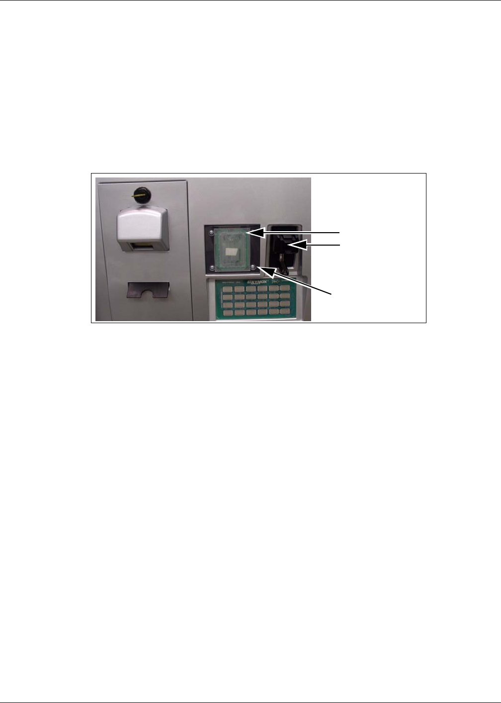
Installing the Antenna PCA (M08285A001)
The RF antenna must be located directly behind the area where the MasterCard PayPass®,
American Express® ExpressPaySM and other logo graphics are attached as shown in Figure 11.
Figure 11: Encore S Main Door Showing Antenna PCA Location
PayPass Logo
Location
Front View Rear View
M05170A001 Antenna PCA
2-pin Connector
K85492-56 Foam
Tape (On the Backside)
Mounting Holes
Encore S
E-CIM
To install the antenna, proceed as follows:
1Remove the small bracket holding in the TRIND blanking panel, and knock out the TRIND
blanking panel (see Figure 12) using a hammer.
Figure 12: Encore S EMV Door with the Blanking Panel
Encore S EMV Door with Blanking
Panel
Preliminary
Installation of the TCR
Page 18 MDE-4770 Tribrid Card Reader Installation Manual · June 2008
2Remove the narrow sealing gasket from the exposed TRIND lens space on the outside of the
door and replace it with the TRIND gasket (M06010B002).
3Locate the M08285A001 Antenna PCA placed on the TRIND CSC Reader Lens
(M05987B002) and place it over the TRIND gasket. Secure the TRIND CSC Reader Lens by
installing and tightening the four screws (M00419B117) (see Figure 13).
4Connect one end of the M07703A001 Antenna Cable to the Card Reader antenna connector of
the TCR top (see Figure 7 on page 14) and the other end of the antenna cable to the 2-pin
connector on the M08285A001 PCA antenna (see Figure 11 on page 17).
Figure 13: Antenna PCA on TRIND CSC Reader Lens
Antenna PCA
(M08285A001)
TCR
TRIND Gasket
(M06010B002)
5Repeat steps 1 to 4 on the other side of the unit.
Preliminary
MDE-4770 Tribrid Card Reader Installation Manual · June 2008 Page 19
Installation of the TCR
Commissioning the Dispenser/Updating CRIND Software
For EMV units, after installing the TCR, you will have to commission the dispenser. At this
point, you may also update the EMV CRIND software using the SPOTUpdate tool. For
detailed instructions on how to commission the dispenser and update the EMV CRIND
software, refer to MDE-4771 EMV CRIND Start-up/Service Manual.
Completing the Installation for Encore S Units (with Contactless Card
Reader Option)
To complete the installation, proceed as follows:
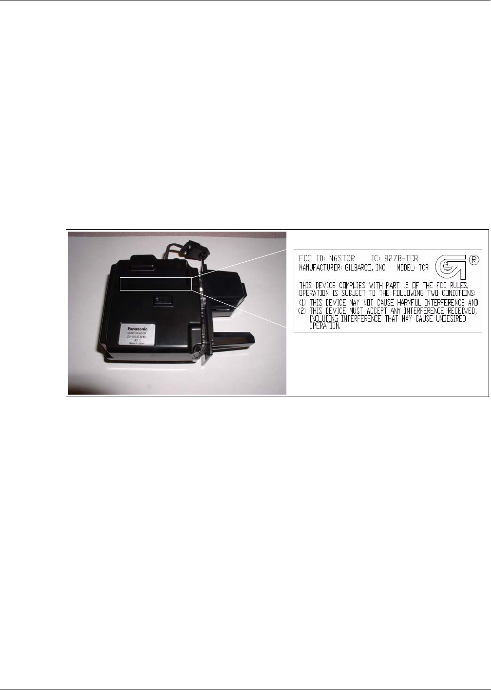
1Install the N23951-14 FCC Label on the back of the Card Reader as shown in Figure 14.
Figure 14: FCC Label on TCR (Side)
2Close and secure the main doors using the security latch and the main door lock. Reinstall and
lock the lower panel door.
3Test the RF Readers by sliding the CRIND diagnostic card (Q12534) through both the readers
with the magnetic strip facing upwards.
4Pass the Card Reader test card in front of the RF antenna (flat side towards the antenna).
5Verify if a valid read was made from the test card. The CRIND beeper will emit an audible
beep upon performing a successful read.
Note: The test card should be read from a minimum distance of 1 inch when presented parallel
to the bezel surface.
6Apply the appropriate graphic logos. Refer to MDE-4625 Graphics Panel Application and
Repair for graphic application instructions.
Note: Graphic logos are order entry items.
Preliminary
Installation of the TCR
© 2008 Gilbarco Inc.
7300 West Friendly Avenue · Post Office Box 22087
Greensboro, North Carolina 27420
Phone (336) 547-5000 · http://www.gilbarco.com · Printed in the U.S.A.
MDE-4770 Tribrid Card Reader Installation Manual · June 2008
American Express® is a registered trademark of American Express Co. CRIND®, Eclipse®, Encore®, Gilbarco®, and TRIND® are registered
trademarks of Gilbarco Inc. ExpressPaySM is a service mark of American Express Co. MasterCard® and PayPass® are registered trademarks
of MasterCard International, Inc. UL® is a registered trademark of Underwriters Laboratories Inc. Visa® is a registered trademark of Visa
International Service Association.
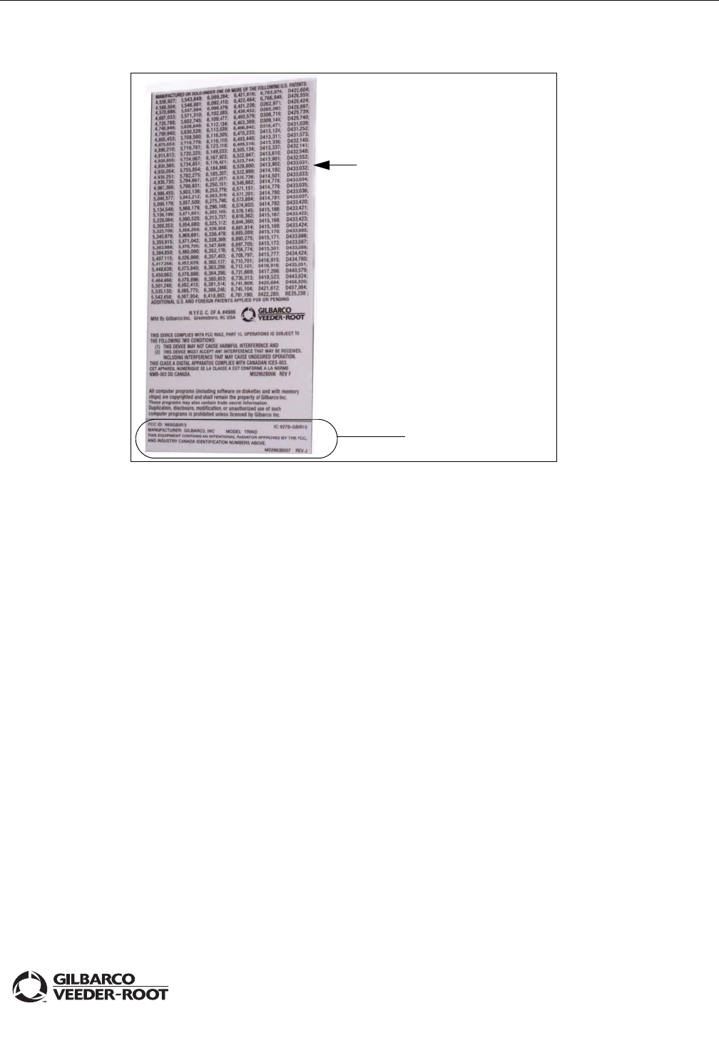
7Obtain the FCC Decal (M02962B011) from the kit and install it under the patent label.
TRIND FCC Label
Nameplate (M02962B011)
Patent Label