Given Imaging SMARTPILL Capsule User Manual SmartPill pH p
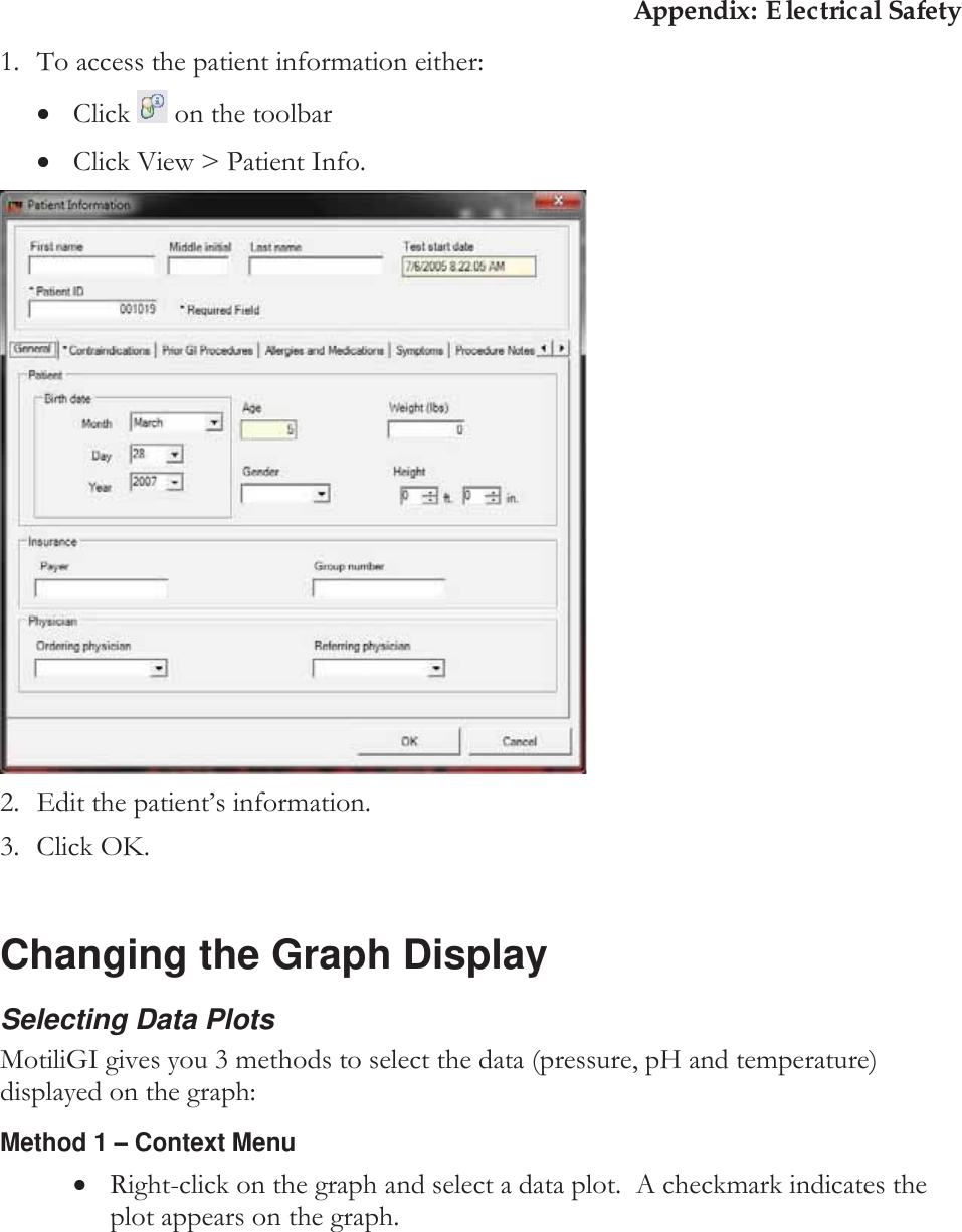
Given Imaging Limited Capsule SmartPill pH p
UserManual.wiki
>
Given Imaging
>
SMARTPILL User Manual
User_manual
Navigation menu
Upload a User Manual
Namespaces
Wiki Guide
HTML
PDF
Info
Views
User Manual
Discussion / Help
Navigation
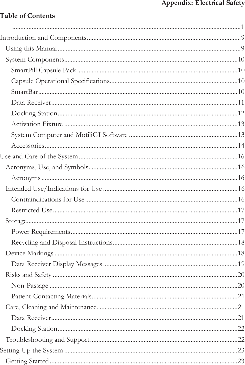


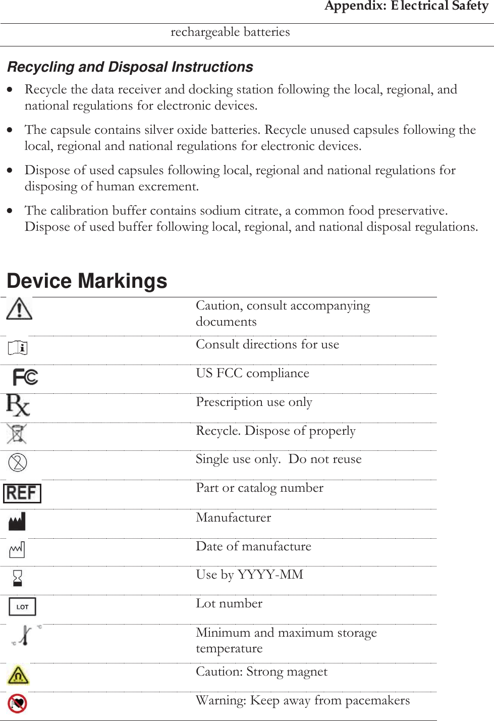
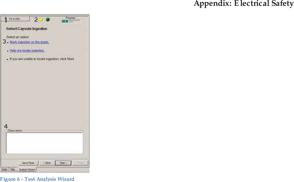
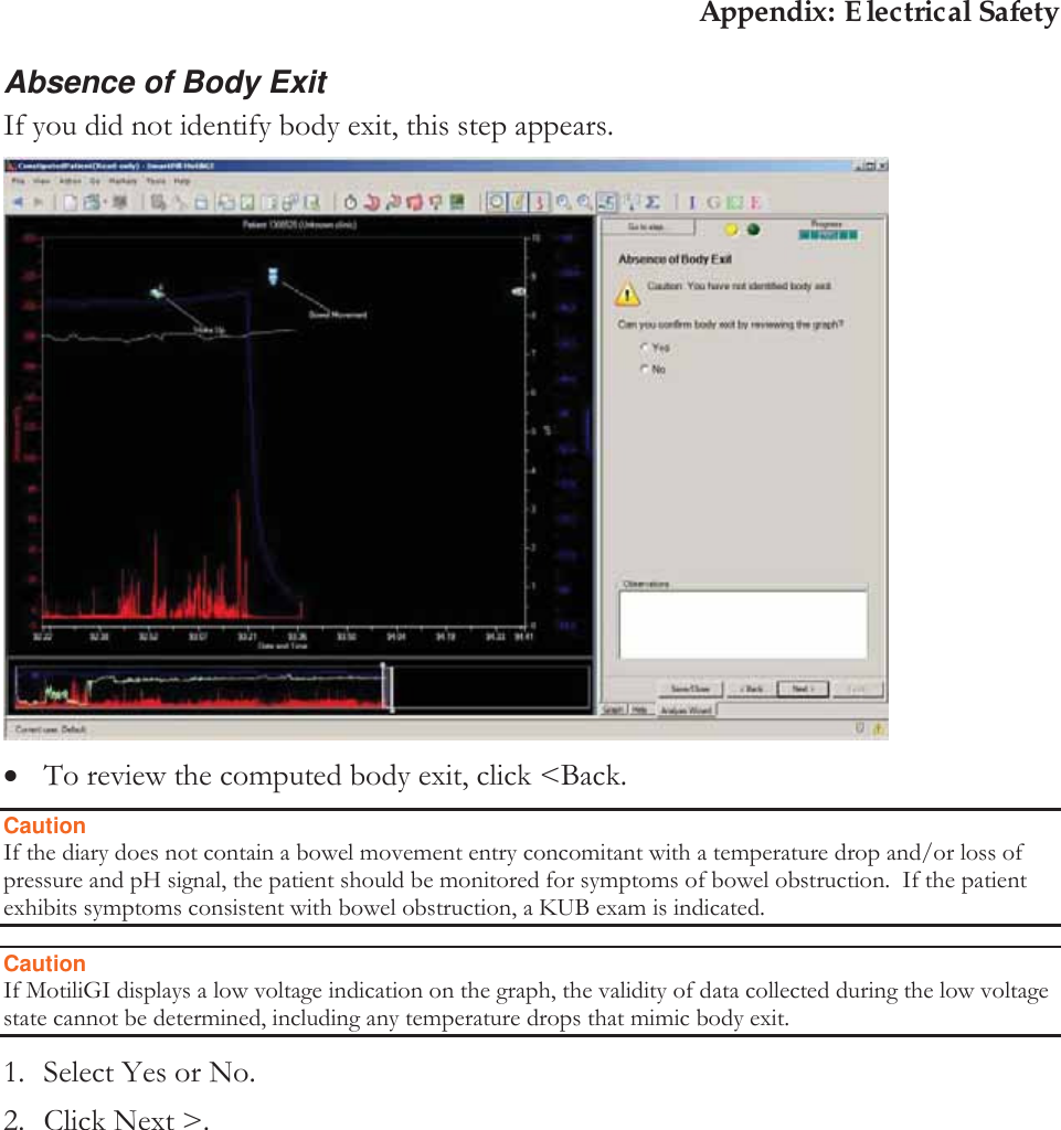
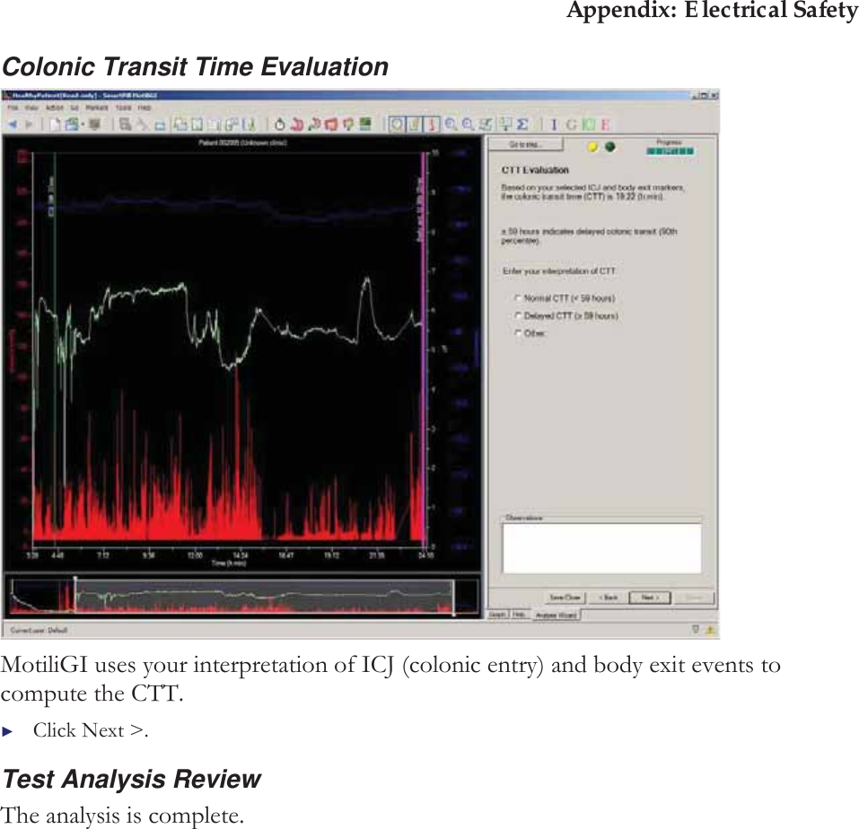
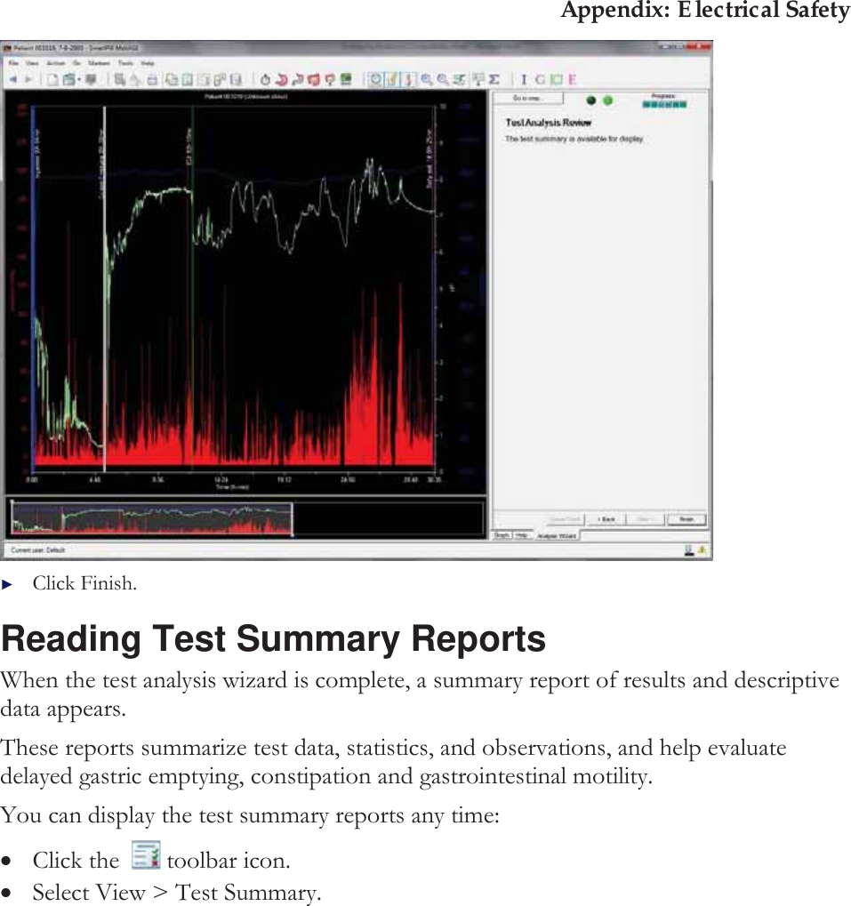
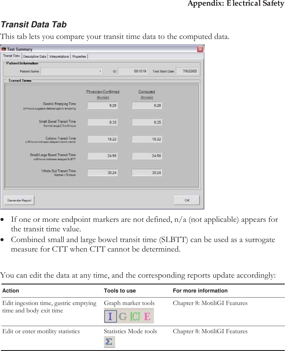
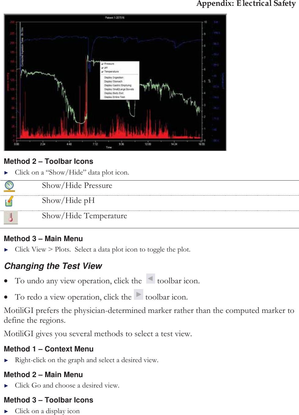
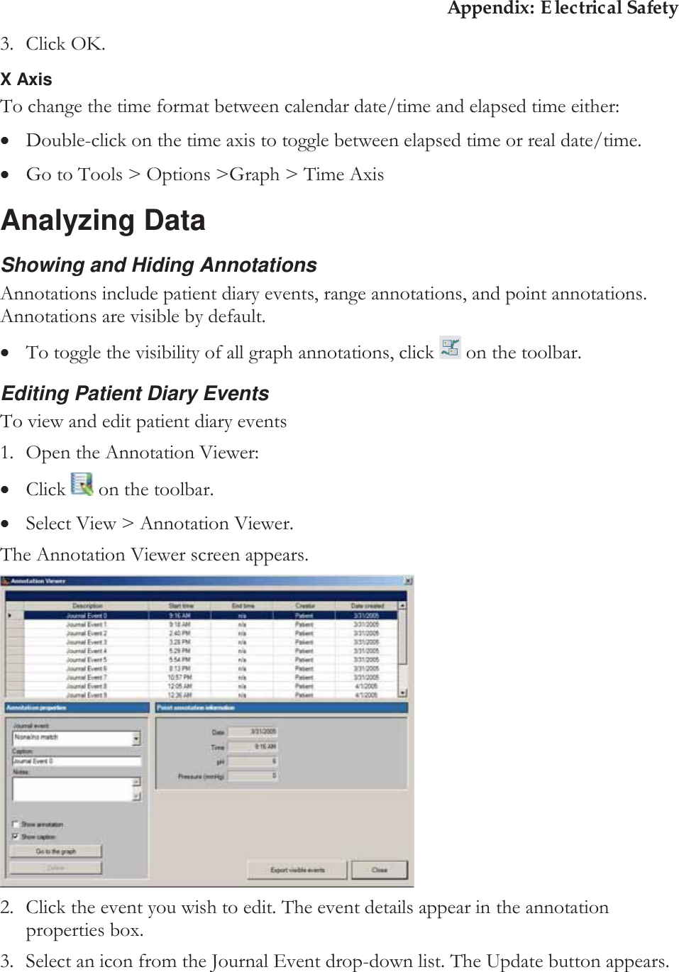
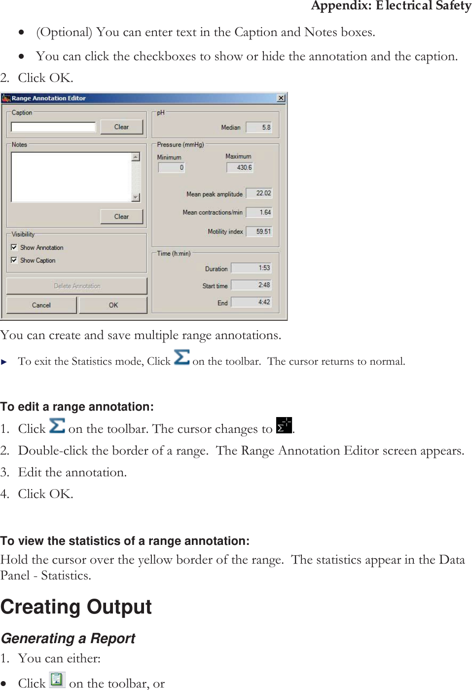
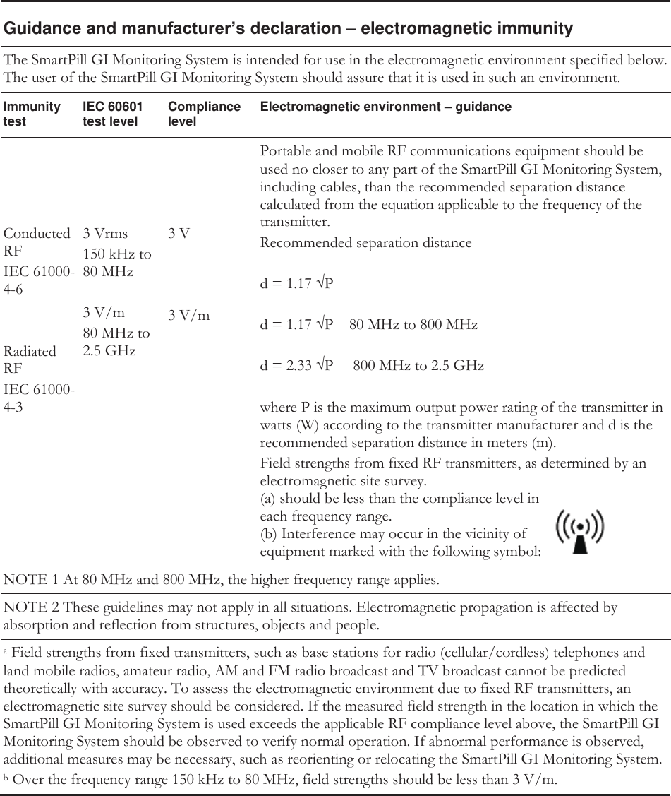
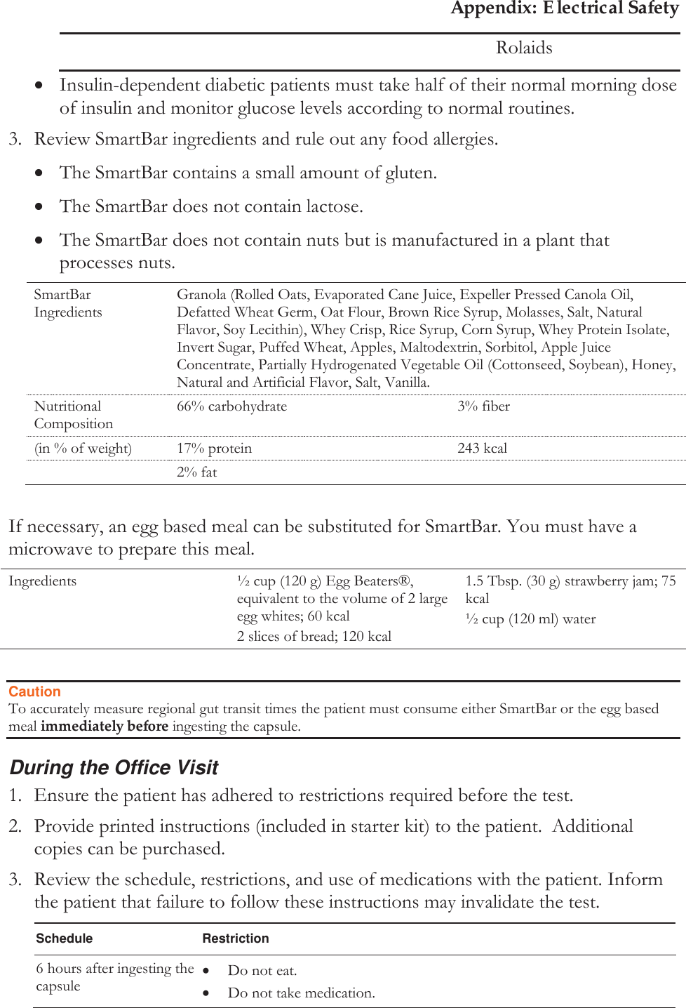
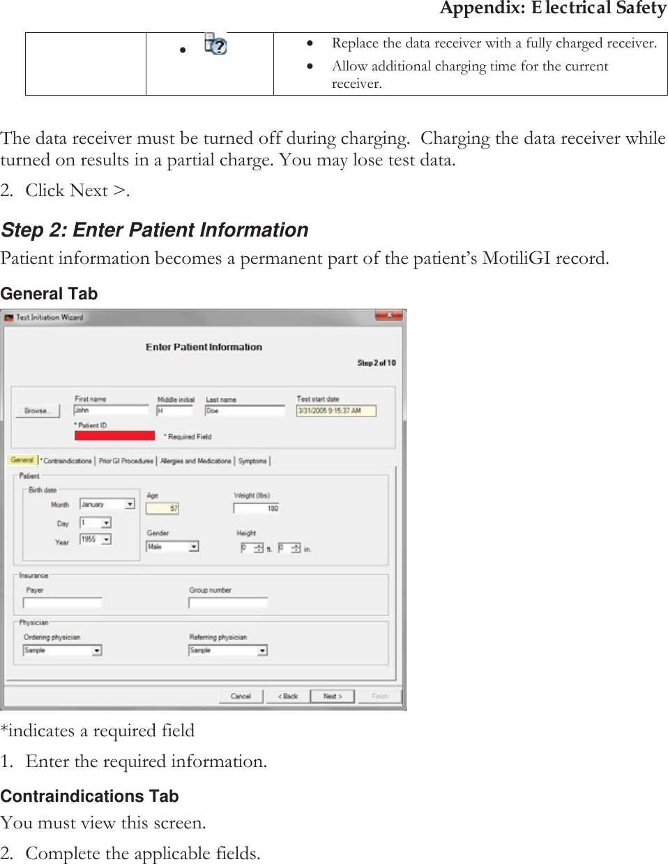
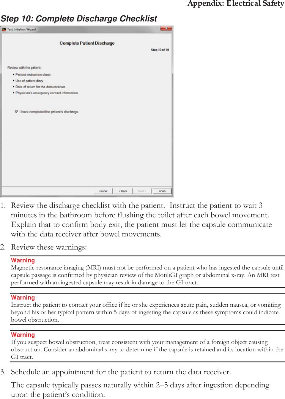
![Appendix: Electrical Safety BF Type BF equipment 0123 CE marking and notified body number Authorized representative Sufficient for one test IP57 Ingress protection rating Serial number Fragile Keep dry Data Receiver Display Messages Looking for capsule—appears during test initiation before the receiver receives the first data packet from the capsule. Locked onto capsule—appears after the data receiver receives first data packet from the capsule. Test in progress—appears when a test is in progress and the data receiver is turned off and back on. Data to download—appears when the data receiver stops collecting data and has data to be downloaded. Time Capsule and data receiver status icons / [X] indicates a failure Signal Strength Pressure pH Indicates the data receiver is writing data from the capsule. Indicates the event button is pushed. The capsule’s data was received. / [X] indicates the data was not received.](https://usermanual.wiki/Given-Imaging/SMARTPILL/User-Guide-2290351-Page-19.png)
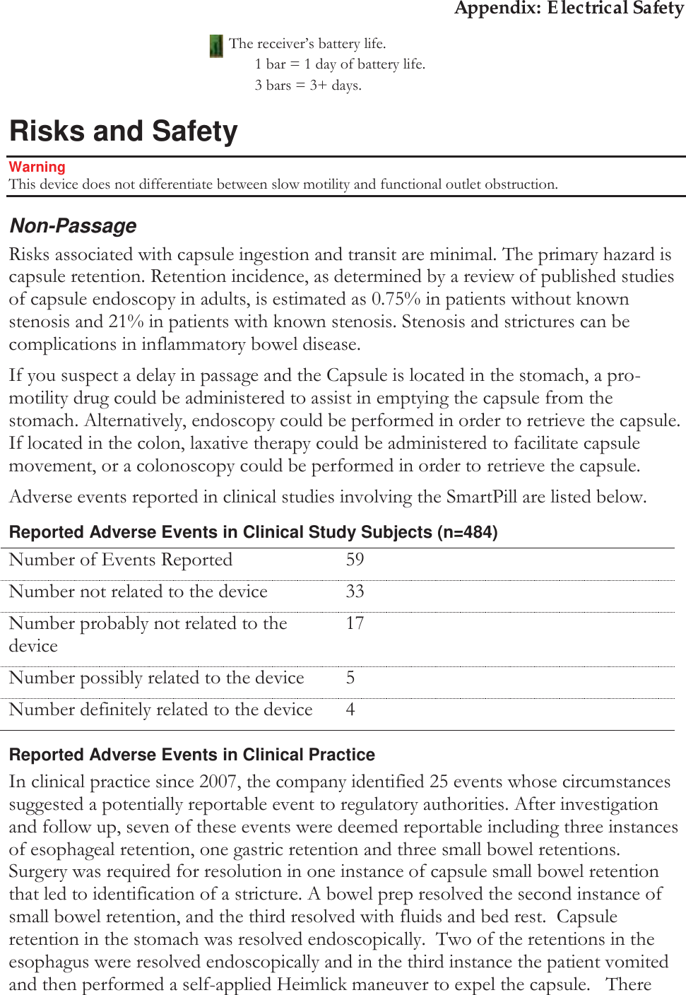
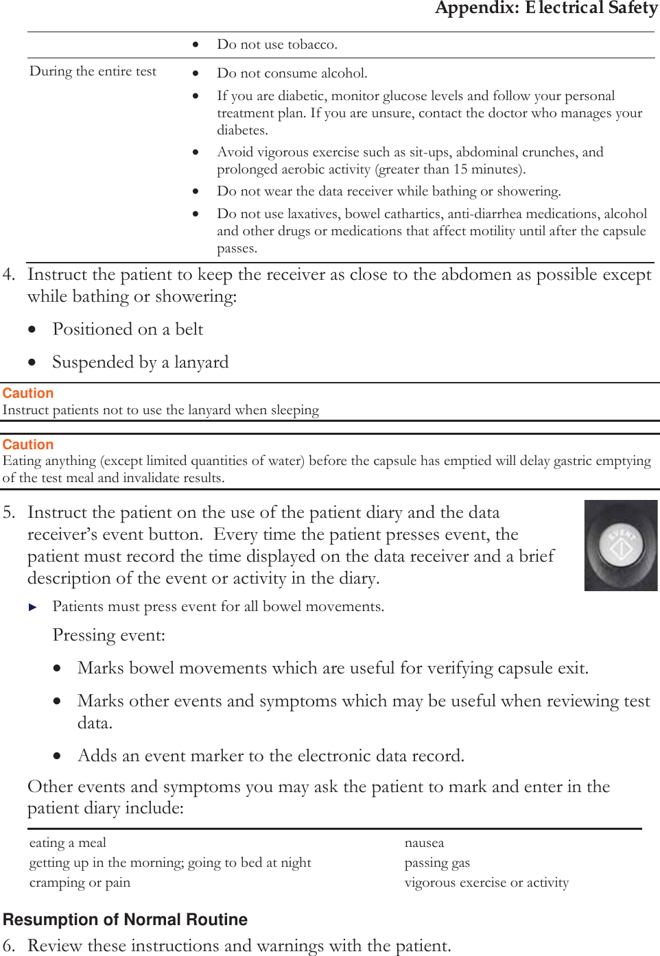
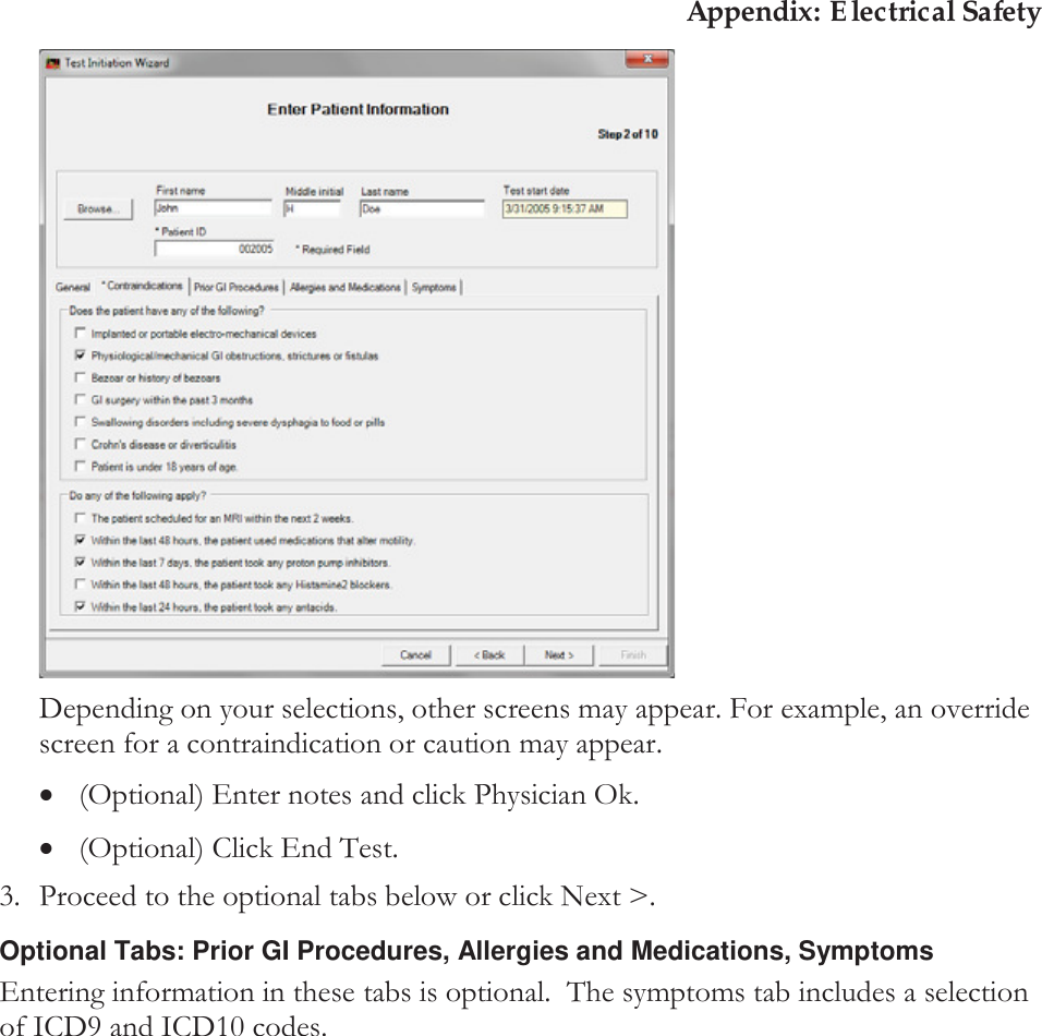

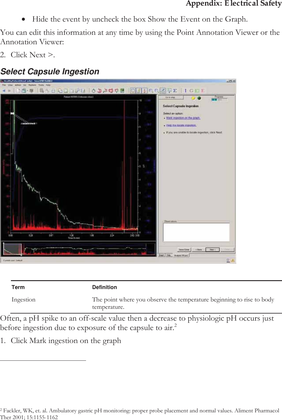
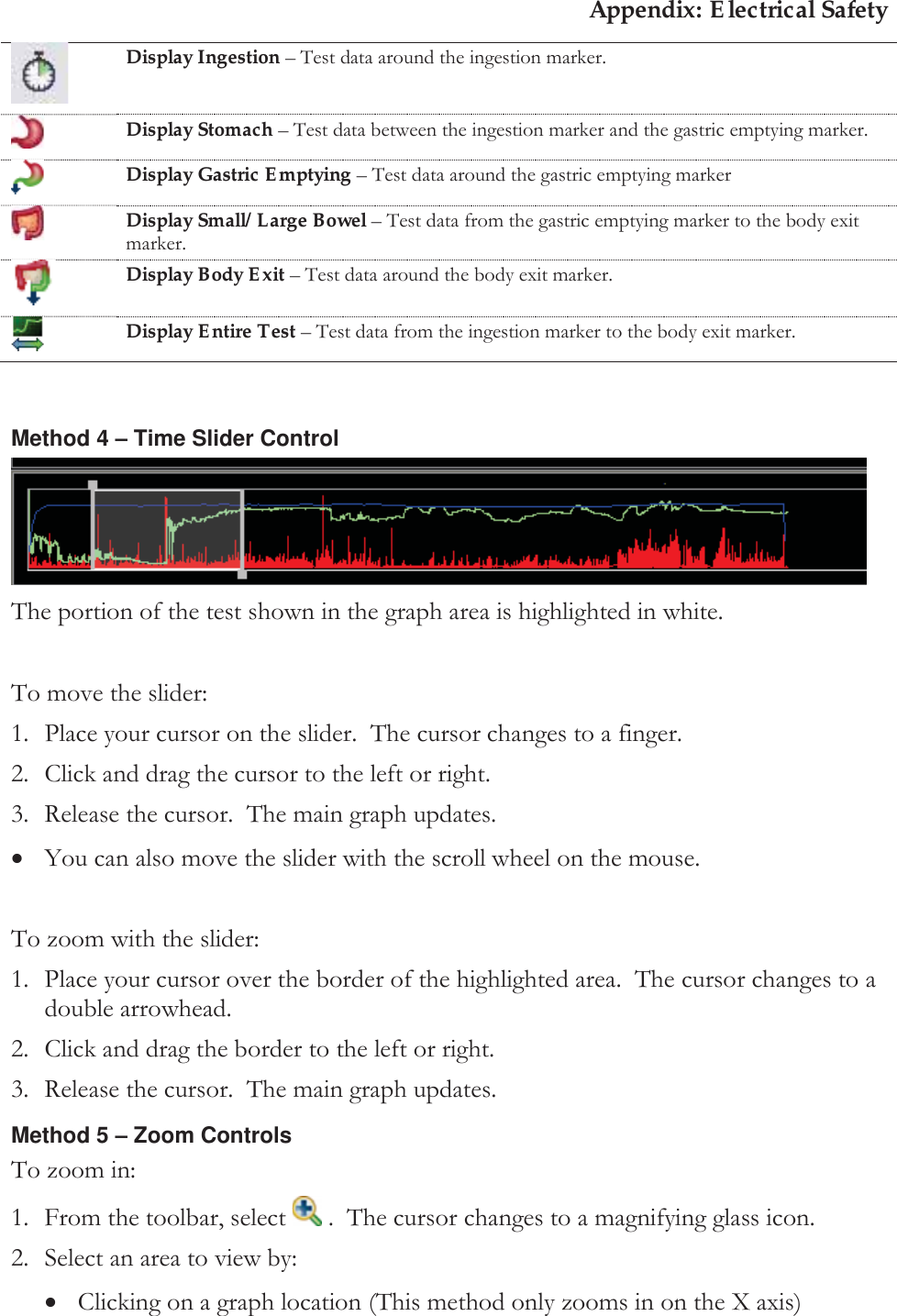
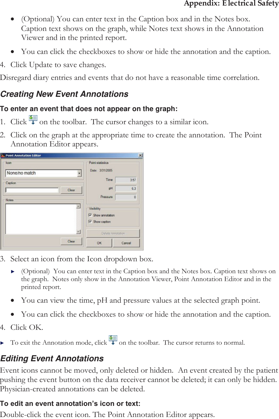
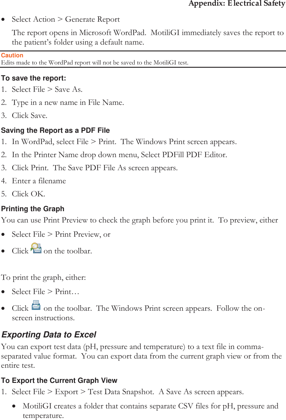
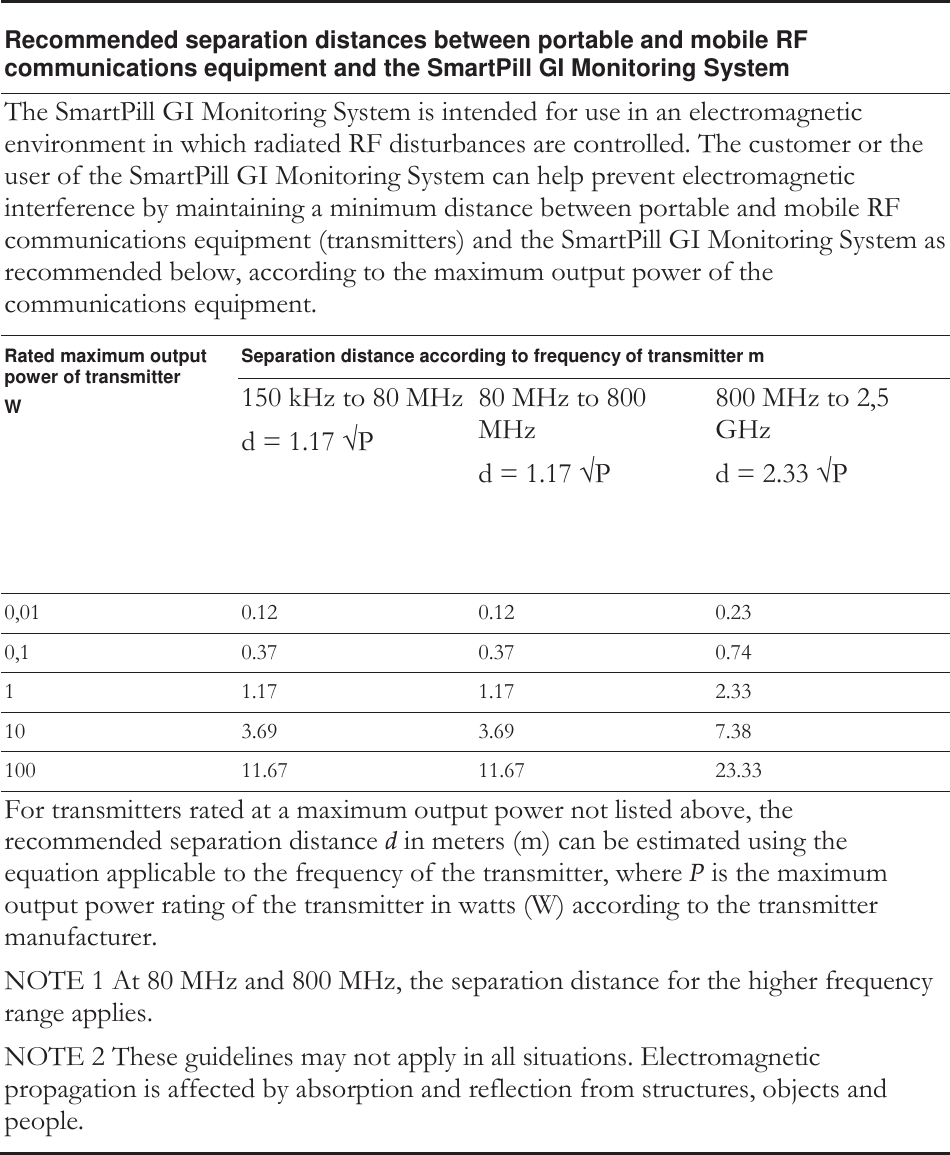
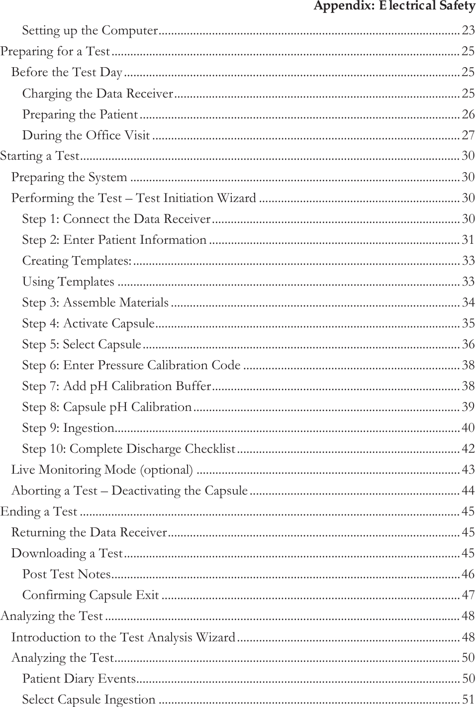
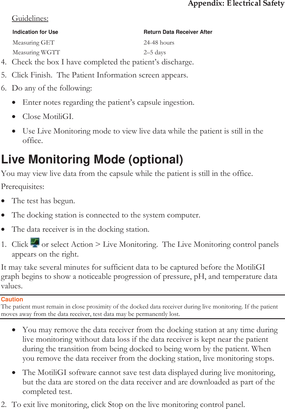
![Appendix: Electrical Safety xThe data receiver’s display then indicates the capsule’s data: Capsule Serial number SS = signal strength P = pressure The capsule’s data was received. / [X] = The data was not received. xThe icon appears in the lower-right corner of MotiliGI: . ►If the capsule did not activate, repeat the procedure. 4. Click Next >. 5. If you wish to deactivate the test, see Aborting a Test – Deactivating the Capsule, Page 44. Step 5: Select Capsule All activated capsules (ingested or not yet ingested) within range of the data receiver appear1. This process may take up to 1 minute. 1 The data receiver can detect the capsule in open air (not ingested) at distances of up to 40 feet.](https://usermanual.wiki/Given-Imaging/SMARTPILL/User-Guide-2290351-Page-36.png)
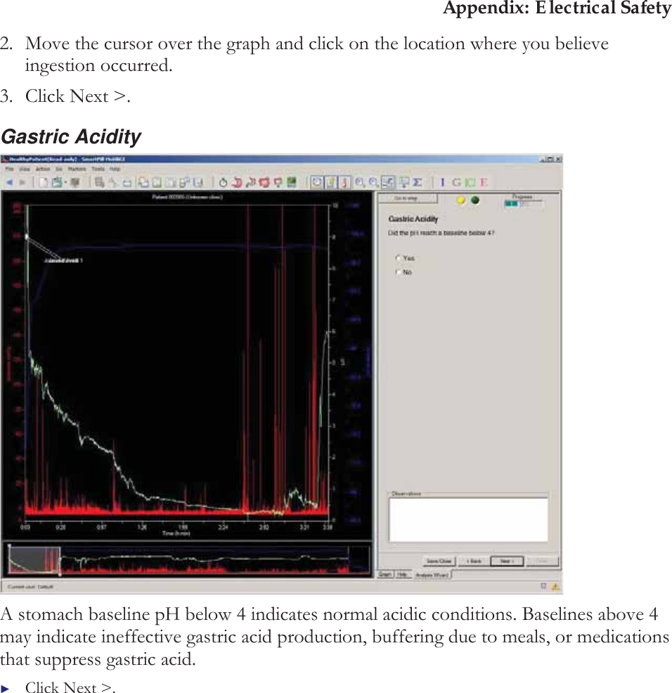
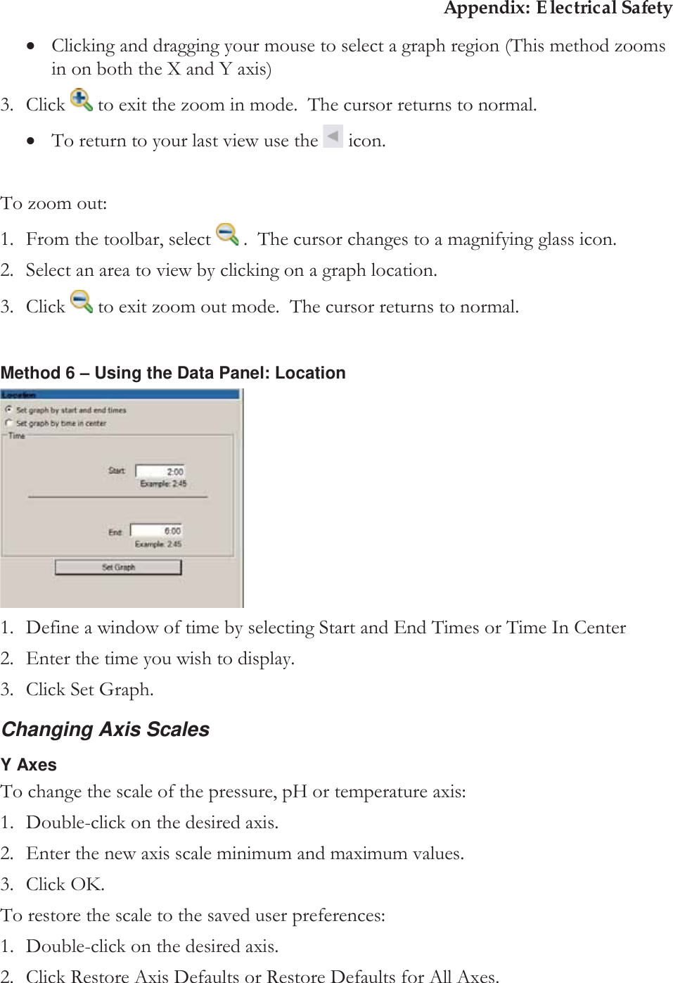
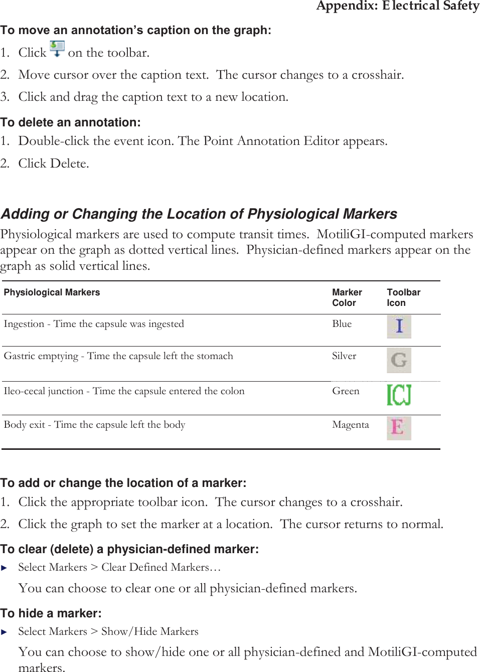
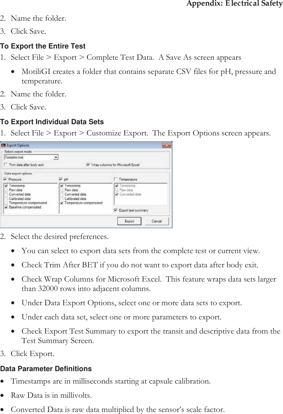
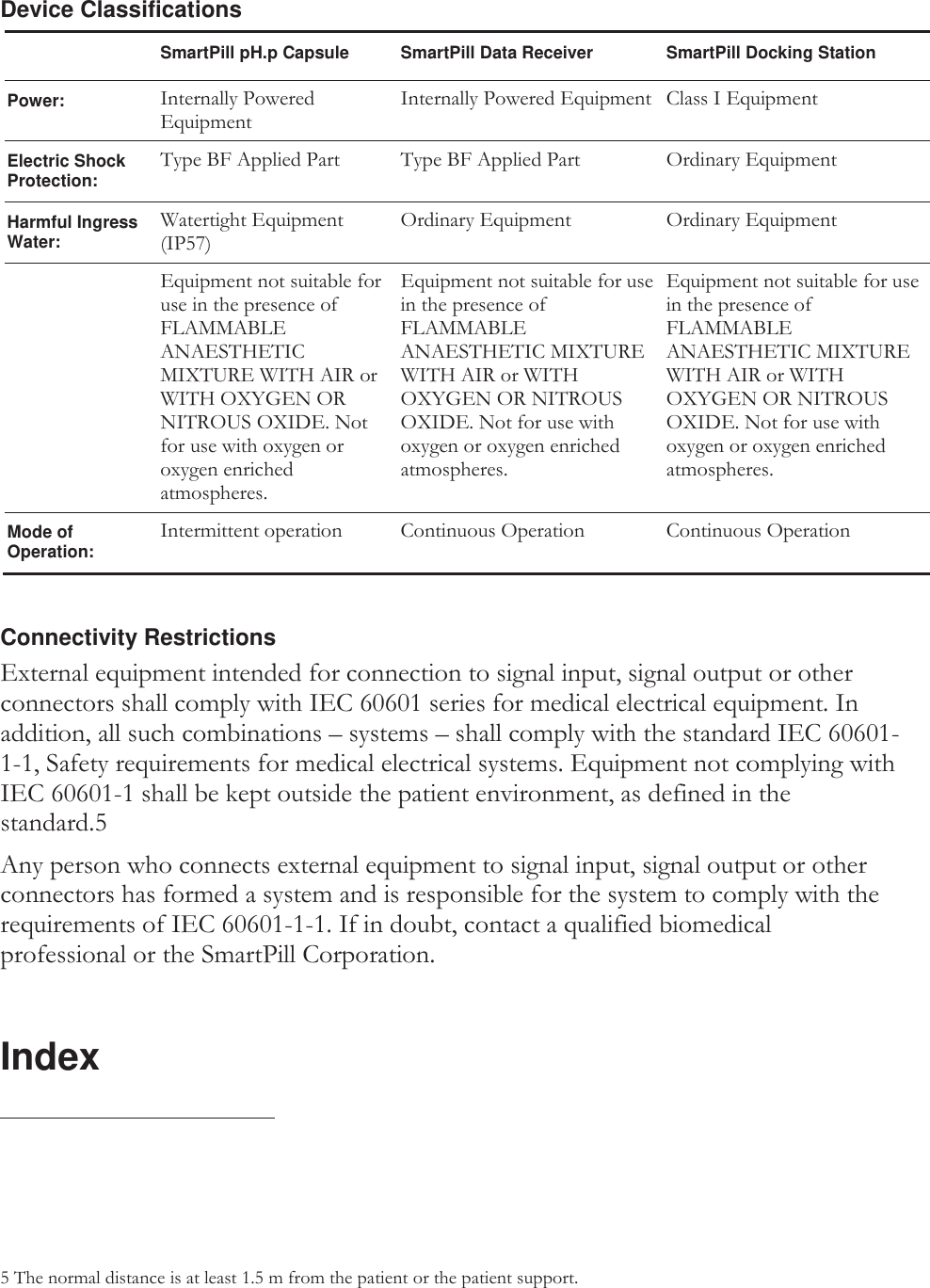
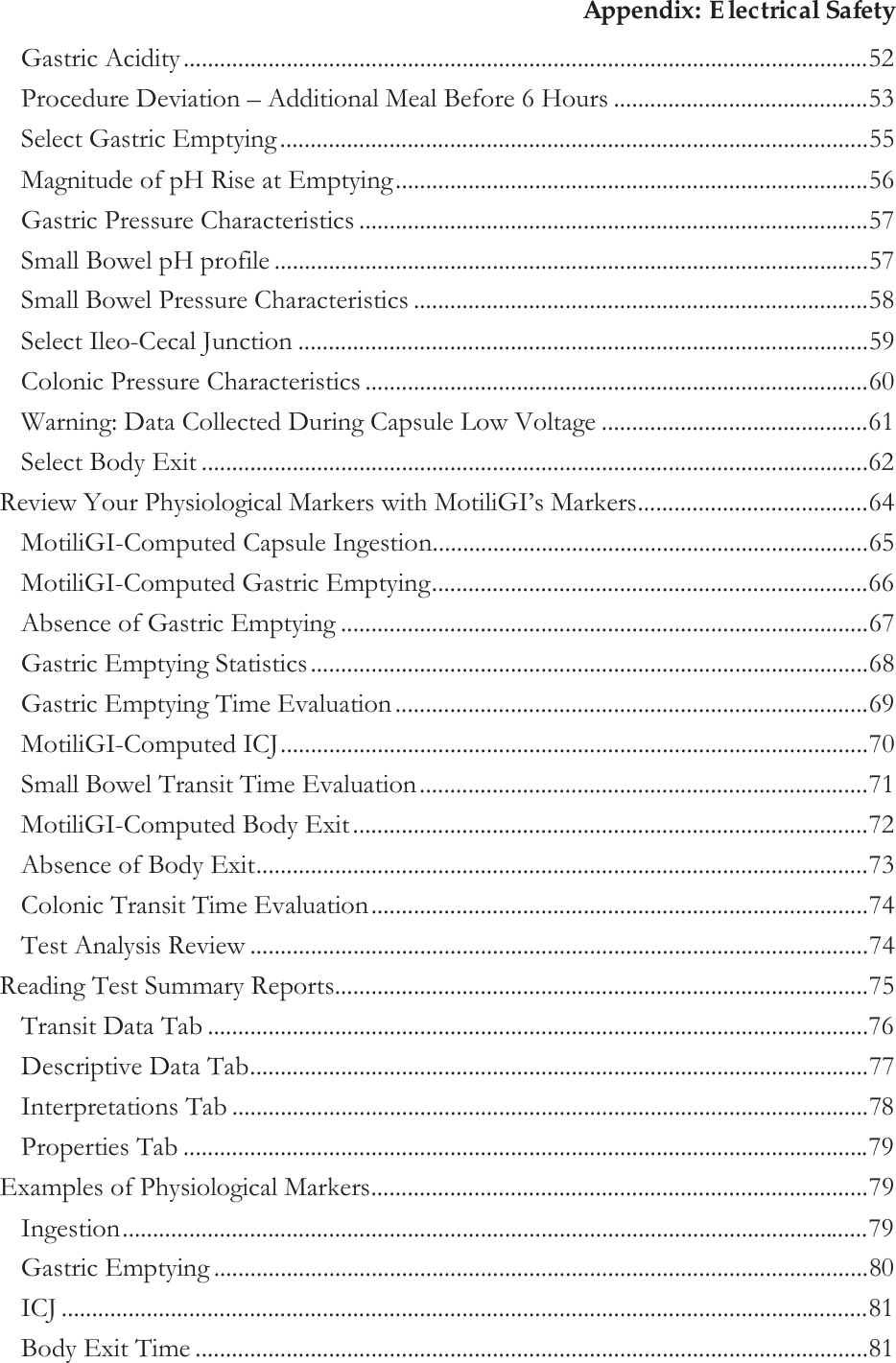
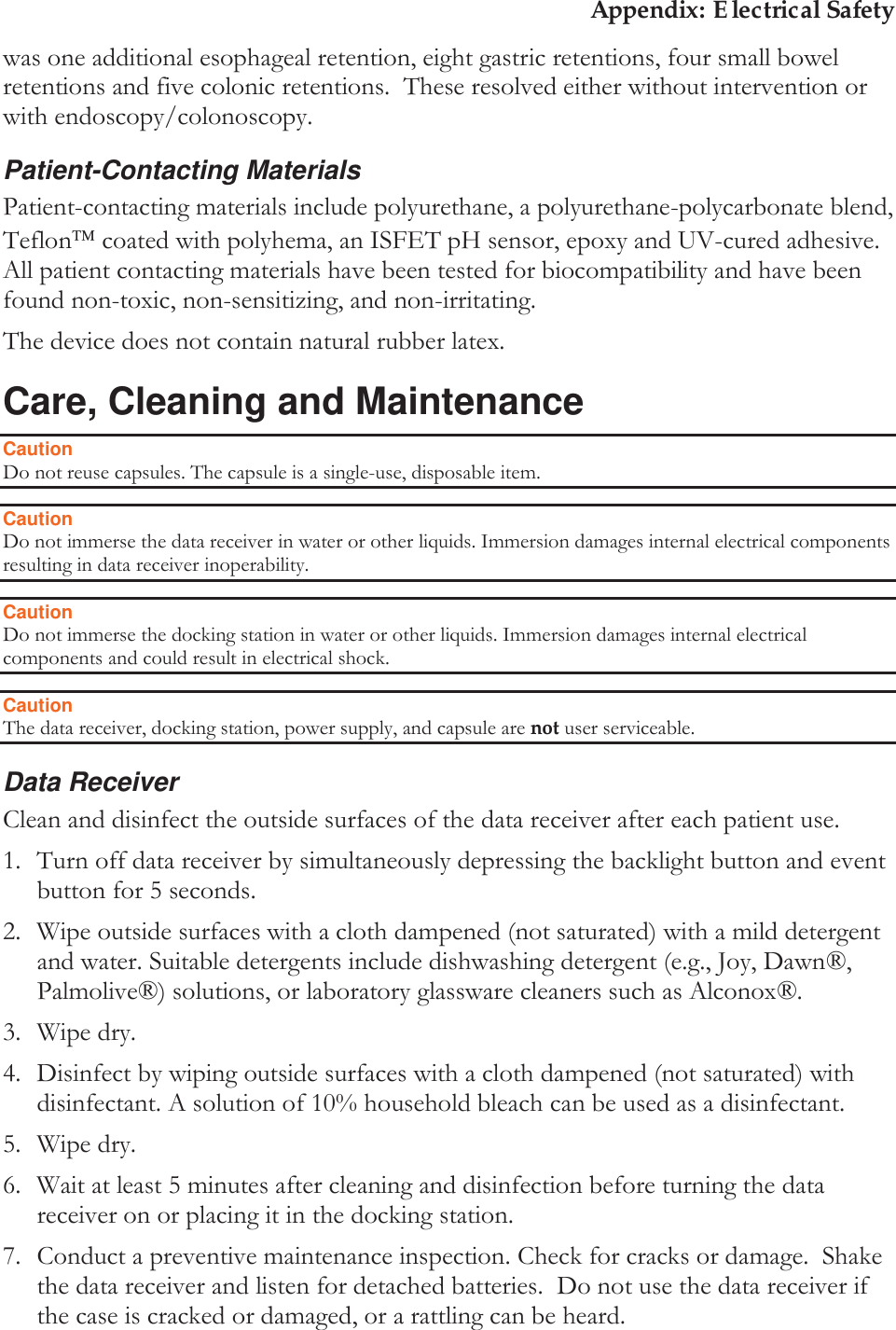
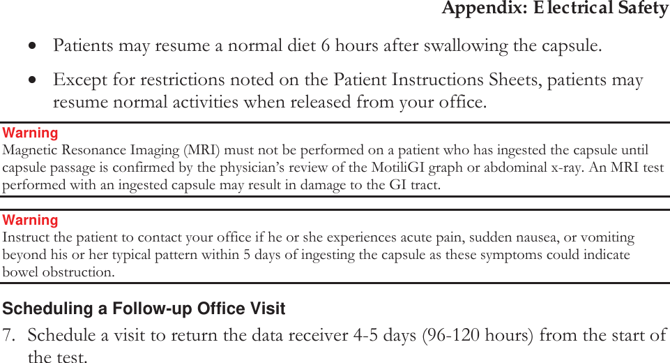
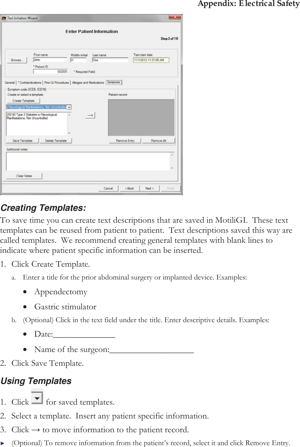
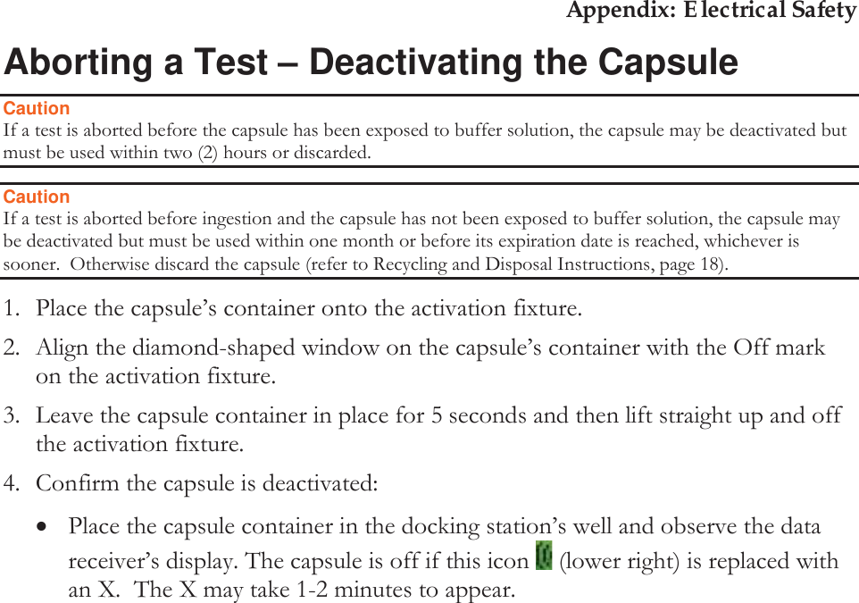
![Appendix: Electrical Safety 1. To select the capsule you activated, click the row that matches the capsule container’s serial number. An arrow indicates your selection. xIf the software does not detect the capsule within a minute, observe the data receiver’s display to confirm the capsule is active. xIf the capsule is activated the data receiver displays this data during a test. Time Capsule and data receiver status icons / [X] indicates a failure Signal Strength Pressure pH Indicates the data receiver is writing data from the capsule. Indicates the event button is pushed. The capsule’s data was received. / [X] = The data was not received. The receiver’s battery life. 1 bar = 1 day of battery life. 3 bars = 3+ days. 2. Click Next >.](https://usermanual.wiki/Given-Imaging/SMARTPILL/User-Guide-2290351-Page-37.png)
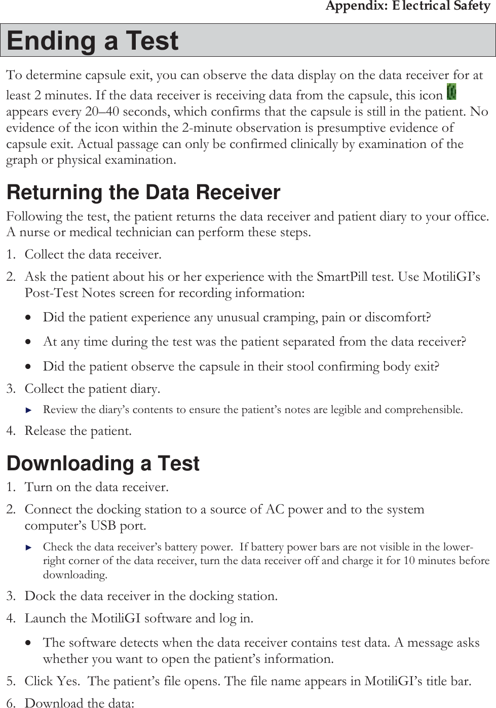
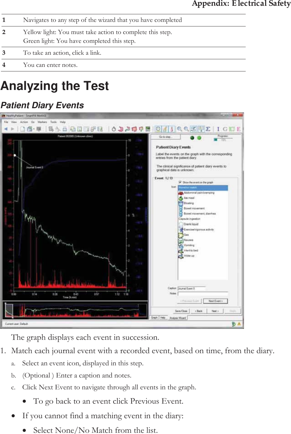
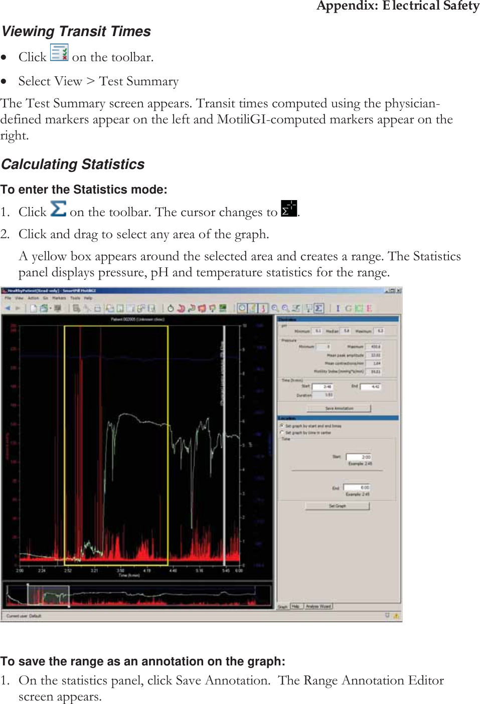
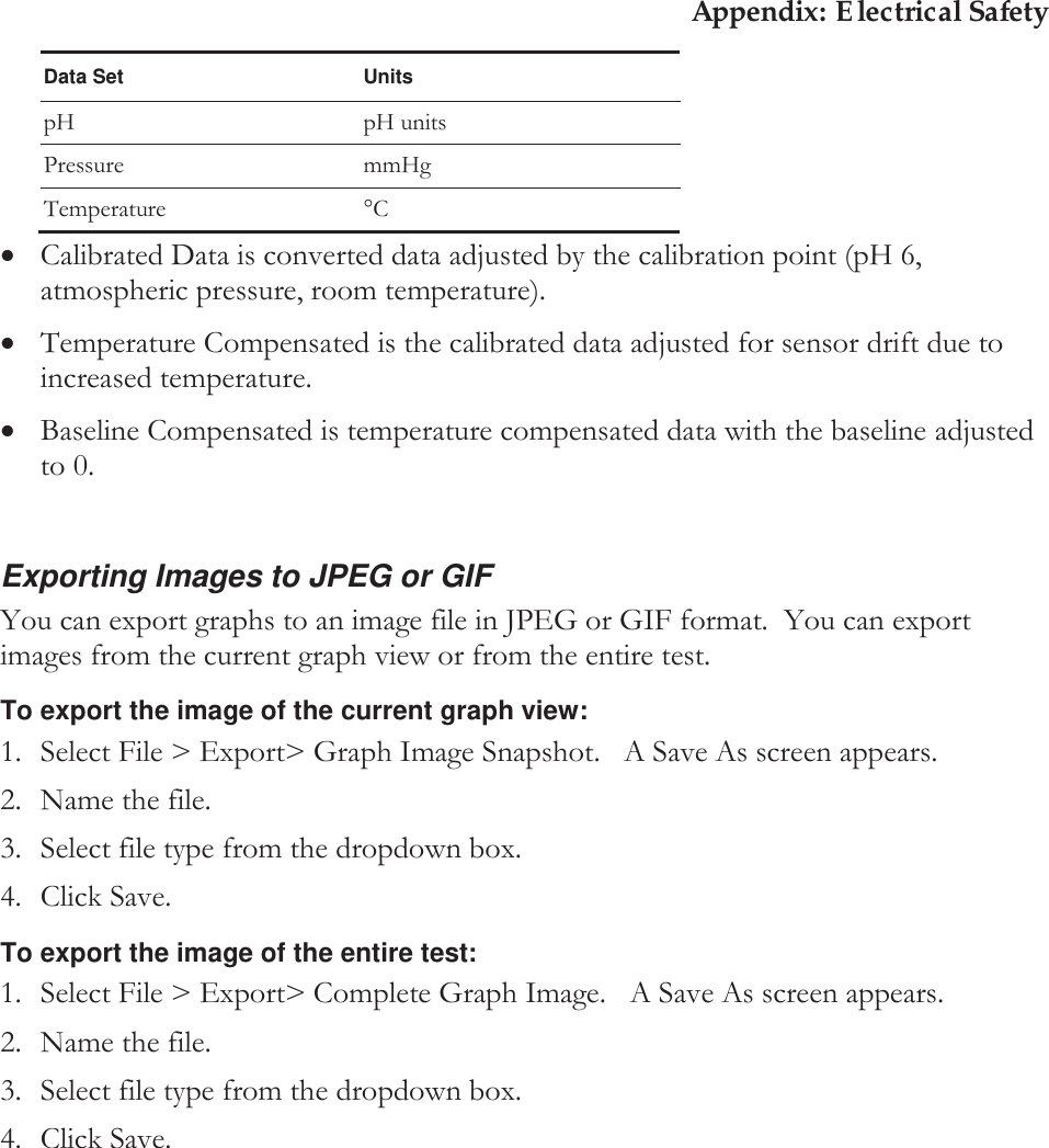
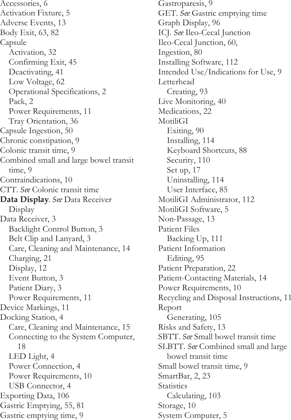
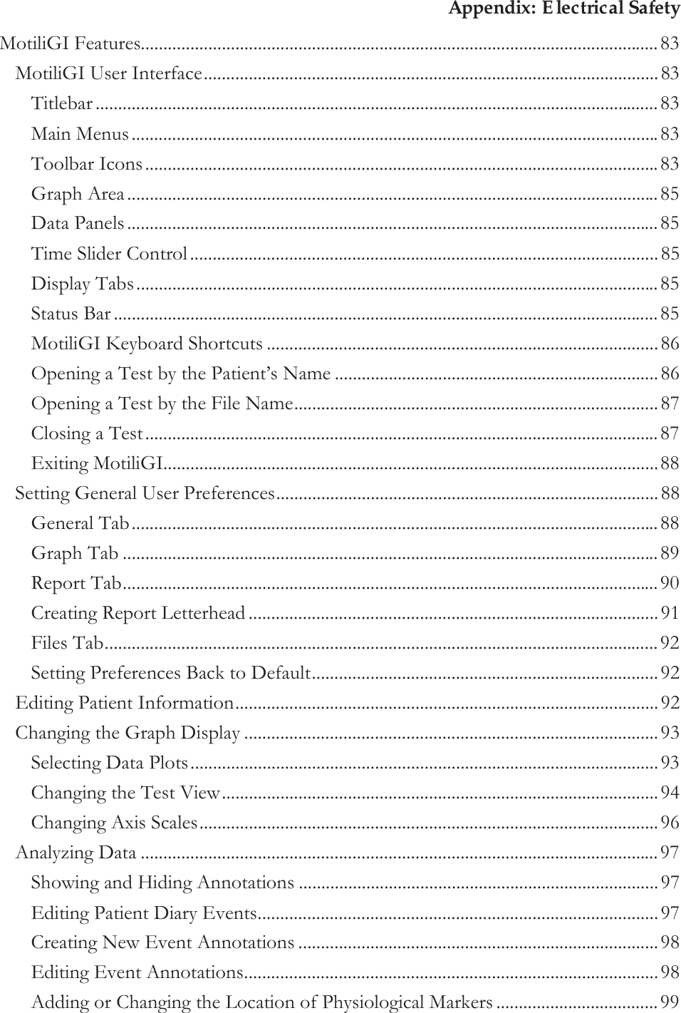
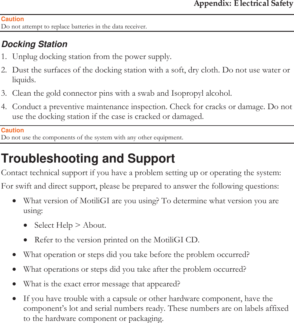
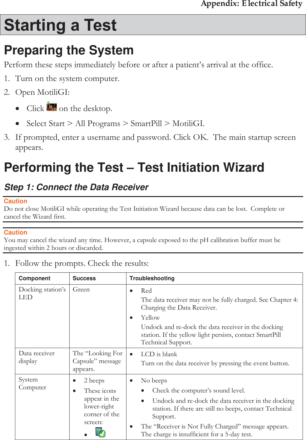
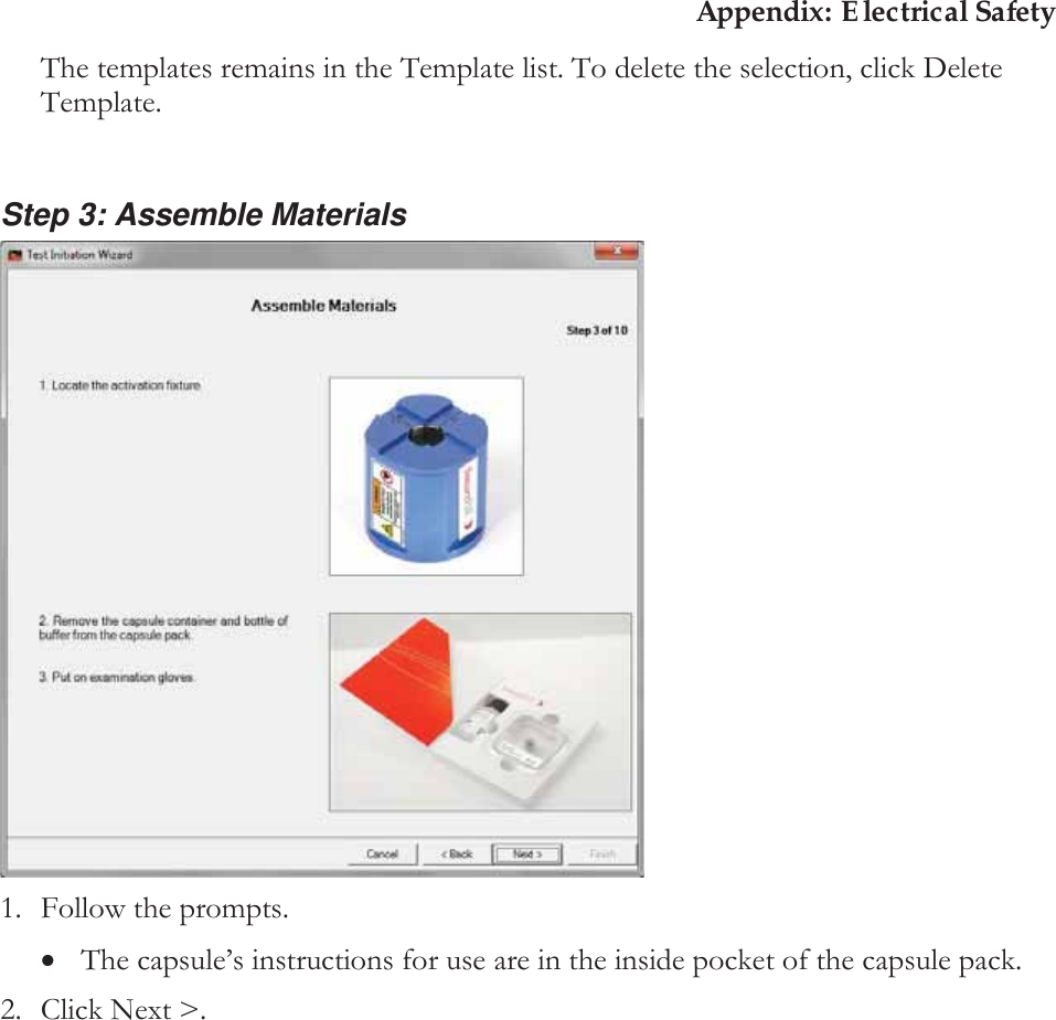
![Appendix: Electrical Safety $QDO\]LQJWKH7HVWThe MotiliGI software identifies capsule ingestion, gastric emptying, ICJ, body exit, and computes GET, SBTT, CTT, SLBTT, WGTT, and motility indices. You can: xMatch events with patient diary entries. xAnalyze test to mark capsule ingestion, gastric emptying, ICJ and body exit. xCompare the markers you defined with markers identified by the MotiliGI software. Introduction to the Test Analysis Wizard After downloading a test, a message appears asking if you want to analyze the test. 1. Click Yes. The Test Analysis Wizard appears. You may close the wizard at any time. If you close the wizard before completing the analysis: xThe Test Summary screen does not appear. xThe test report will contain the note “Test data not reviewed by physician.” xThe test wizard automatically saves. To re-open the wizard: xClick the toolbar icon. xSelect Action > Analyze Test. The test analysis wizard resumes from your last completed step.](https://usermanual.wiki/Given-Imaging/SMARTPILL/User-Guide-2290351-Page-48.png)