Glenayre Electronics GL-T8311SA Power Service Load Management Transmitter User Manual
Glenayre Electronics Inc Power Service Load Management Transmitter
Contents
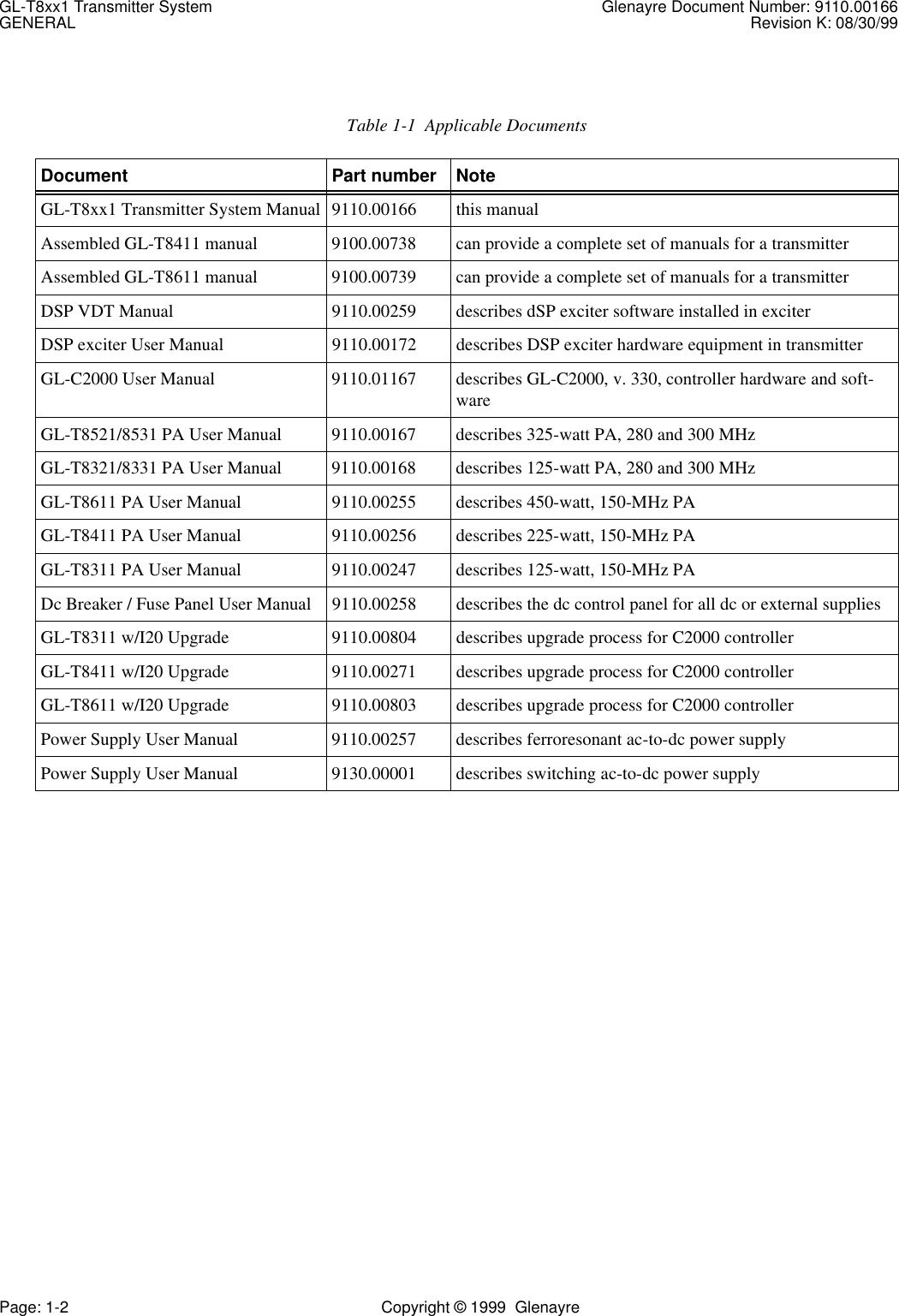
- 1. Exciter Manual and Calibration Procedure
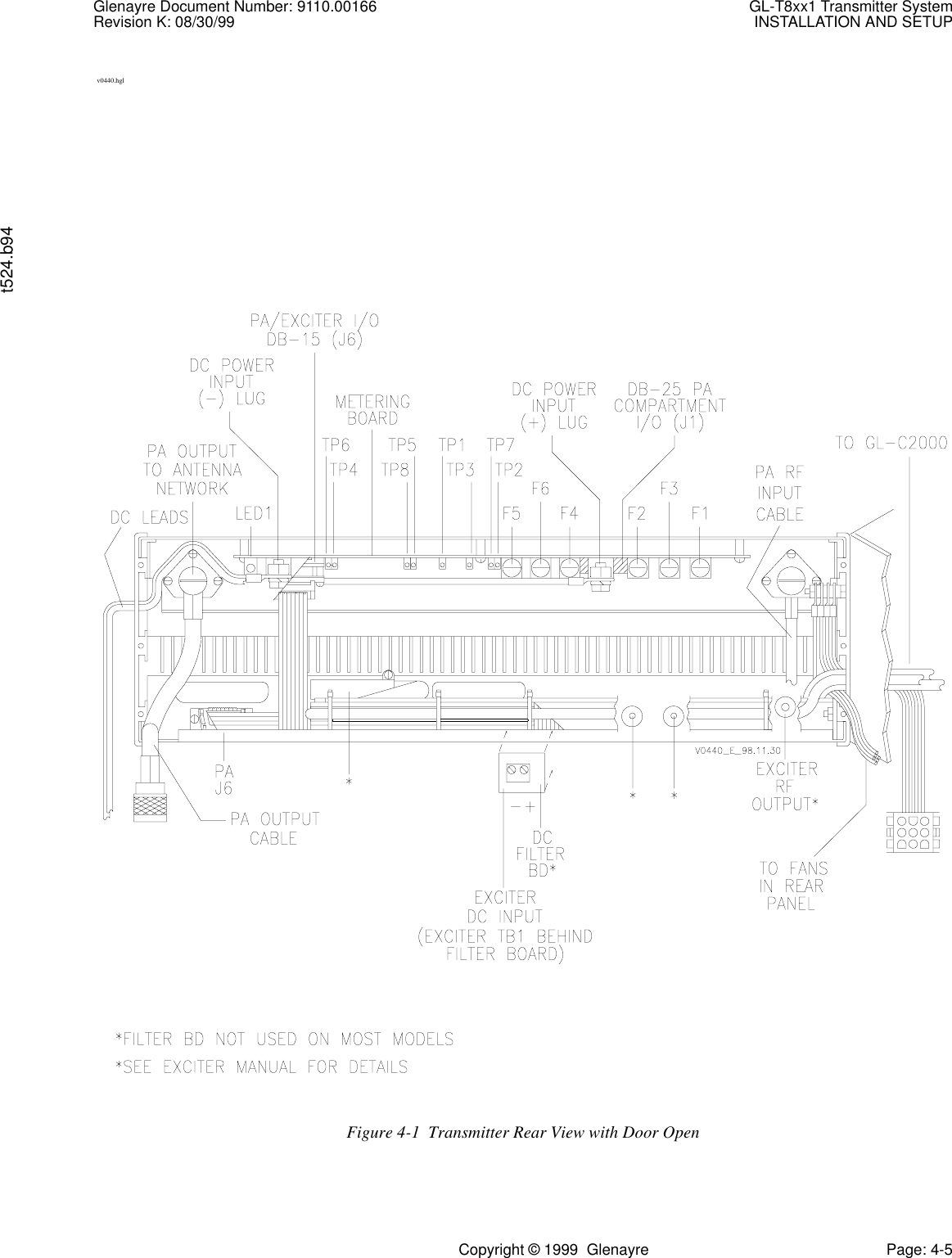
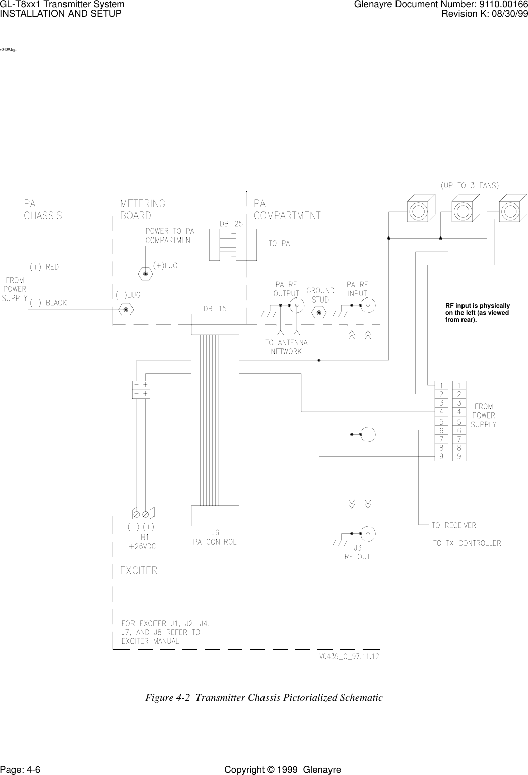
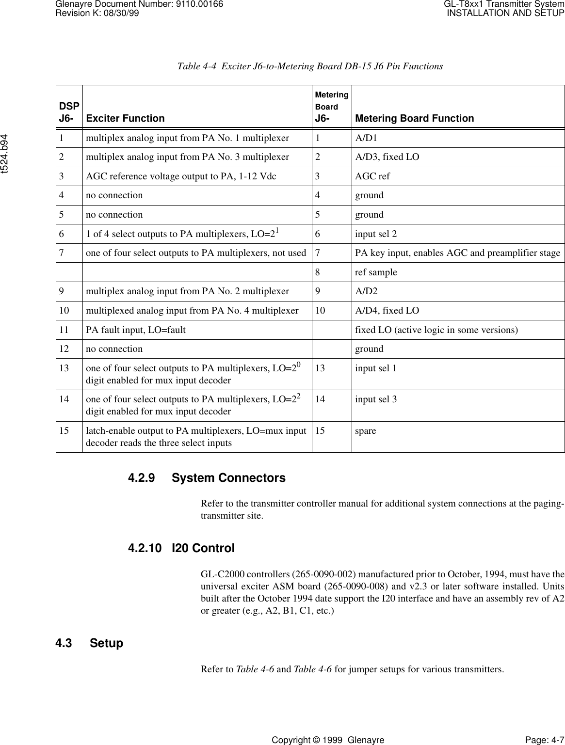
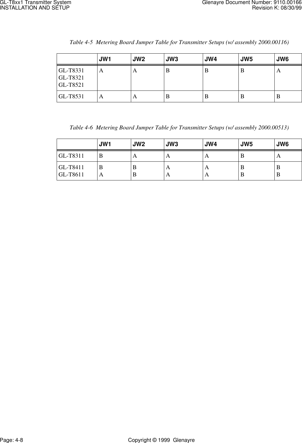
- 2. Power Amplifier User Manual
Power Amplifier User Manual