Glenayre Electronics GL-T8311SA Power Service Load Management Transmitter User Manual
Glenayre Electronics Inc Power Service Load Management Transmitter
Contents
- 1. Exciter Manual and Calibration Procedure
- 2. Power Amplifier User Manual
Power Amplifier User Manual
Copyright © 1999 Glenayre
GL-T8xx1 Transmitter System Revision K: 08/30/99
Specifications subject to change without notice
Copyright © 1999 Glenayre
All rights reserved. No part of this work may be reproduced or copied in any form or by
any means—graphic, electronic, or mechanical, including photocopying, recording,
taping, or information-retrieval system—without written permission of Glenayre.
GL-T8311,
GL-T8321,
GL-T8331,
GL-T8411,
GL-T8521,
GL-T8531,
and
GL-T8611 Transmitters
USER MANUAL
PN 9110.00166 (old pn = 916-8B21-001)
REV K
GL-T8xx1 Transmitter System Glenayre Document Number: 9110.00166
Document Change Record Revision K: 08/30/99
Copyright © 1999 Glenayre
Document Change Record
Issue: 1, Preliminary
Date:
Changes: none, original
Issue: 1, Preliminary
Date: 06/19/95
Changes: front page...part number, copyright
Issue: 1, Released, Rev C
Date: 04/29/96
Changes: obtained released status
Issue: 1, Released, Rev D
Date: 07/08/96
Changes: fan control...metering board...I20 control
Issue: 1, Released, Rev E
Date: 02/26/97
Changes: changed jumper table settings on metering board functional diagram
Issue: 1, Released, Rev F
Date: 06/18/97
Changes: added new metering bd. info w/pics ... added info to specifications
Issue: 1, Released, Rev G
Date: 10/17/97
Changes: changed typical PA top view picture reflecting switching of low-pass filter
and directional coupler board on GL-T8521 and GL-T8321 transmitters
Issue: 1, Released, Rev H
Date: 12/01/97
Changes: updated schematics of metering boards 2000.00116 and 2000.00513; deleted
reference for using 2000.00513 on GL-T8521, GL-T8321, GL-T8531, or GL-T8331 trans-
mitters; deleted reference for using 2000.00116 on GL-T8311, GL-T8411, or GL-T8611
transmitters; updated jumper settings on 2000.00116
Issue: 1, Released, Rev J
Date: 05/14/99
Changes: Added information defining the three meter (3m) limitation on the 28Vdc
power cable.
Issue: 1, Released, Rev K
Date: 8/30/99
Changes: added RF output measurement at output of PA or circulator in specifications

Glenayre Document Number: 9110.00166 GL-T8xx1 Transmitter System
Revision K: 08/30/99 Table of Contents
t521.toc
Copyright © 1999 Glenayre Page: -i
Table of Contents
1 GENERAL . . . . . . . . . . . . . . . . . . . . . . . . . . . . . . . . . . . . 1-1
1.1 Manual Scope . . . . . . . . . . . . . . . . . . . . . . . . 1-1
1.2 Applicable Documents. . . . . . . . . . . . . . . . . . . . . 1-1
1.3 About Glenayre . . . . . . . . . . . . . . . . . . . . . . . 1-3
1.3.1 Product Warranty Information . . . . . . . . . . . . . . . . . . .1-4
1.3.2 Service Warranty Information . . . . . . . . . . . . . . . . . . .1-4
2 SPECIFICATIONS . . . . . . . . . . . . . . . . . . . . . . . . . . . . . . . . 2-1
3 DESCRIPTION . . . . . . . . . . . . . . . . . . . . . . . . . . . . . . . . . . 3-1
3.1 Conceptual Description . . . . . . . . . . . . . . . . . . . . 3-1
3.2 Physical Description. . . . . . . . . . . . . . . . . . . . . . 3-1
3.2.1 Mounting Provisions . . . . . . . . . . . . . . . . . . . . . . . .3-1
3.2.1.1 PA and Exciter Assemblies . . . . . . . . . . . . . . .3-1
3.2.1.2 Power Supply . . . . . . . . . . . . . . . . . . . . . .3-1
3.2.1.3 Video Display Terminal. . . . . . . . . . . . . . . . .3-2
3.3 Simplified Paging-Site Functional Description . . . . . . . . . . . 3-3
3.3.1 Paging Site . . . . . . . . . . . . . . . . . . . . . . . . . . . . .3-3
3.3.2 Communications Equipment and Transmitter Controller. . . . . .3-3
3.3.3 Paging Transmitter . . . . . . . . . . . . . . . . . . . . . . . . .3-3
3.3.3.1 DSP Exciter . . . . . . . . . . . . . . . . . . . . . . .3-3
3.3.3.2 Power Amplifier RF Compartment . . . . . . . . . . .3-7
3.3.3.3 Metering Board . . . . . . . . . . . . . . . . . . . . .3-7
3.3.3.4 Power Supply . . . . . . . . . . . . . . . . . . . . . .3-7
3.3.3.4.1 Ac-Powered Sites. . . . . . . . . . . . . . . . . . .3-7
3.3.3.4.2 Dc-Powered Sites. . . . . . . . . . . . . . . . . . .3-7
3.3.4 Video Display Terminal. . . . . . . . . . . . . . . . . . . . . . .3-7
3.4 Site Signal Flows . . . . . . . . . . . . . . . . . . . . . . . 3-8
3.4.1 Site RF-Signal Flow. . . . . . . . . . . . . . . . . . . . . . . . .3-8
3.4.2 Site Audio-Signal Flow . . . . . . . . . . . . . . . . . . . . . . .3-8
3.4.3 Site Control-Signal Flow . . . . . . . . . . . . . . . . . . . . . .3-8
3.4.4 Status-Signal Flow . . . . . . . . . . . . . . . . . . . . . . . . .3-9
GL-T8xx1 Transmitter System Glenayre Document Number: 9110.00166
Table of Contents Revision K: 08/30/99
Page: -ii Copyright © 1999 Glenayre
4 INSTALLATION AND SETUP . . . . . . . . . . . . . . . . . . . . . . . . . 4-1
4.1 Inspection . . . . . . . . . . . . . . . . . . . . . . . . . 4-1
4.2 Installation . . . . . . . . . . . . . . . . . . . . . . . . . 4-1
4.2.1 Tools and Equipment Required. . . . . . . . . . . . . . . . . . . 4-1
4.2.2 Rack Positioning . . . . . . . . . . . . . . . . . . . . . . . . . . 4-1
4.2.3 Rack Grounding . . . . . . . . . . . . . . . . . . . . . . . . . . 4-2
4.2.4 Positioning within the Rack . . . . . . . . . . . . . . . . . . . . 4-2
4.2.5 Primary Power Requirements. . . . . . . . . . . . . . . . . . . . 4-2
4.2.5.1 Special Considerations . . . . . . . . . . . . . . . . . 4-3
4.2.6 Equipment Cabling . . . . . . . . . . . . . . . . . . . . . . . . . 4-3
4.2.6.1 Ac Connections . . . . . . . . . . . . . . . . . . . . . 4-3
4.2.6.2 Dc Connections . . . . . . . . . . . . . . . . . . . . . 4-3
4.2.6.3 Dc-Only Sites. . . . . . . . . . . . . . . . . . . . . . 4-3
4.2.7 PA Chassis Connections . . . . . . . . . . . . . . . . . . . . . . 4-3
4.2.8 Metering Board Connections . . . . . . . . . . . . . . . . . . . . 4-4
4.2.9 System Connectors . . . . . . . . . . . . . . . . . . . . . . . . . 4-7
4.2.10 I20 Control . . . . . . . . . . . . . . . . . . . . . . . . . . . . . 4-7
4.3 Setup . . . . . . . . . . . . . . . . . . . . . . . . . . . 4-7
4.4 Ultimate Disposition . . . . . . . . . . . . . . . . . . . . . 4-10
5 OPERATION . . . . . . . . . . . . . . . . . . . . . . . . . . . . . . . . . . . 5-1
5.1 Controls and Indicators . . . . . . . . . . . . . . . . . . . . 5-1
5.2 Operation . . . . . . . . . . . . . . . . . . . . . . . . . 5-1
5.2.1 Turn PA On and Off . . . . . . . . . . . . . . . . . . . . . . . . 5-1
5.2.2 Fan(s) Control . . . . . . . . . . . . . . . . . . . . . . . . . . . 5-1
5.2.3 Key and Unkey PA . . . . . . . . . . . . . . . . . . . . . . . . . 5-2
6 THEORY OF OPERATION. . . . . . . . . . . . . . . . . . . . . . . . . . . 6-1
6.1 Metering Board . . . . . . . . . . . . . . . . . . . . . . . 6-1
6.1.1 Dc-Power Distribution . . . . . . . . . . . . . . . . . . . . . . . 6-1
6.1.2 Control-Signal Distribution. . . . . . . . . . . . . . . . . . . . . 6-1
6.1.2.1 Transmitter Keying . . . . . . . . . . . . . . . . . . . 6-1
6.1.2.2 Power-Output Control . . . . . . . . . . . . . . . . . 6-1
6.1.2.3 Signal Measurement and Alarm Gathering. . . . . . . 6-6
6.1.2.4 PA Fault. . . . . . . . . . . . . . . . . . . . . . . . . 6-6

Glenayre Document Number: 9110.00166 GL-T8xx1 Transmitter System
Revision K: 08/30/99 Table of Contents
t521.toc
Copyright © 1999 Glenayre Page: -iii
7 MAINTENANCE . . . . . . . . . . . . . . . . . . . . . . . . . . . . . . . . . 7-1
7.1 General . . . . . . . . . . . . . . . . . . . . . . . . . . . 7-1
7.2 PA-Current Check . . . . . . . . . . . . . . . . . . . . . . 7-1
7.3 Dc-Ripple Check . . . . . . . . . . . . . . . . . . . . . . . 7-2
8 CHECKOUT . . . . . . . . . . . . . . . . . . . . . . . . . . . . . . . . . . . 8-1
8.1 General . . . . . . . . . . . . . . . . . . . . . . . . . . . 8-1
8.2 Checkout Procedures . . . . . . . . . . . . . . . . . . . . . 8-1
8.2.1 Dc-Voltage Verification . . . . . . . . . . . . . . . . . . . . . .8-1
8.2.2 VDT Power-up Verification . . . . . . . . . . . . . . . . . . . .8-2
8.2.3 Cooling-Fans Check . . . . . . . . . . . . . . . . . . . . . . . .8-2
9 REMOVAL AND REINSTALLATION. . . . . . . . . . . . . . . . . . . . . 9-1
9.1 Transmitter Chassis . . . . . . . . . . . . . . . . . . . . . . 9-1
9.2 Power Supply . . . . . . . . . . . . . . . . . . . . . . . . 9-1
9.3 PA RF Compartment . . . . . . . . . . . . . . . . . . . . . 9-1
9.4 Exciter Removal and Reinstallation. . . . . . . . . . . . . . . . 9-2
9.5 Metering Board Removal and Reinstallation . . . . . . . . . . . . 9-3
9.6 Fan Removal and Reinstallation . . . . . . . . . . . . . . . . . 9-4
GL-T8xx1 Transmitter System Glenayre Document Number: 9110.00166
Table of Contents Revision K: 08/30/99
Page: -iv Copyright © 1999 Glenayre

Glenayre Document Number: 9110.00166 GL-T8xx1 Transmitter System
Revision K: 08/30/99 List of Figures
t521.lof
Copyright © 1999 Glenayre Page: -v
List of Figures
Figure 3-1 Transmitter Chassis Isometric Front View . . . . . . . . . . . . . . . . 3-2
Figure 3-2 Typical PA Top Views . . . . . . . . . . . . . . . . . . . . . . . . . . 3-4
Figure 3-3 Transmitter Functional Diagram . . . . . . . . . . . . . . . . . . . . . 3-9
Figure 4-1 Transmitter Rear View with Door Open . . . . . . . . . . . . . . . . . 4-5
Figure 4-2 Transmitter Chassis Pictorialized Schematic . . . . . . . . . . . . . . . 4-6
Figure 5-1 Metering Board Assembly 2000.00116. . . . . . . . . . . . . . . . . . 5-3
Figure 5-2 Metering Board Assembly 2000.00513. . . . . . . . . . . . . . . . . . 5-4
Figure 6-1 Metering Board 2000.00116 Functional Diagram . . . . . . . . . . . . 6-2
Figure 6-2 Metering Board 2000.00513 Functional Diagram . . . . . . . . . . . . 6-4
GL-T8xx1 Transmitter System Glenayre Document Number: 9110.00166
List of Figures Revision K: 08/30/99
Page: -vi Copyright © 1999 Glenayre

Glenayre Document Number: 9110.00166 GL-T8xx1 Transmitter System
Revision K: 08/30/99 List of Tables
t521.lot
Copyright © 1999 Glenayre Page: -vii
List of Tables
Table 1-1 Applicable Documents . . . . . . . . . . . . . . . . . . . . . . . . . . 1-2
Table 2-1 Specifications . . . . . . . . . . . . . . . . . . . . . . . . . . . . . . . 2-1
Table 4-1 Tools and Equipment . . . . . . . . . . . . . . . . . . . . . . . . . . . 4-1
Table 4-2 PA Chassis Connectors . . . . . . . . . . . . . . . . . . . . . . . . . . 4-3
Table 4-3 Metering Board Connectors. . . . . . . . . . . . . . . . . . . . . . . . 4-4
Table 4-4 Exciter J6-to-Metering Board DB-15 J6 Pin Functions . . . . . . . . . 4-7
Table 4-5 Metering Board Jumper Table for Transmitter Setups (w/ assembly 2000.00116)4-8
Table 4-6 Metering Board Jumper Table for Transmitter Setups (w/ assembly 2000.00513)4-8
Table 4-7 Detail of J1 Connections (DB-25) between
Metering Board and PA RF Compartment . . . . . . . . . . . . . . . . 4-9
Table 5-1 Metering Board Fuses, Indicators, and Test Points. . . . . . . . . . . . 5-2
Table 6-1 Input-Select Metering Lines from Exciter . . . . . . . . . . . . . . . . 6-6
GL-T8xx1 Transmitter System Glenayre Document Number: 9110.00166
List of Tables Revision K: 08/30/99
Page: -viii Copyright © 1999 Glenayre

Glenayre Document Number: 9110.00166 GL-T8xx1 Transmitter System
Revision K: 08/30/99 GENERAL
t521.b94
Copyright © 1999 Glenayre Page: 1-1
1 GENERAL
1.1 Manual Scope
This manual provides information for the following transmitters:
• 325-watt, 280-MHz transmitter, model GL-T8521
• 325-watt, 320-MHz transmitter, model GL-T8531
• 125-watt, 280-MHz transmitter, model GL-T8321
• 125-watt, 320-MHz transmitter, model GL-T8331
• 450-watt, 150-MHz transmitter, model GL-T8611
• 225-watt, 150-MHz transmitter, model GL-T8411
• 125-watt, 150-MHz transmitter, model GL-T8311.
1.2 Applicable Documents
This manual is incomplete without additional manuals. See Table 1-1, Applicable Docu-
ments, for a listing and function of these manuals.

GL-T8xx1 Transmitter System Glenayre Document Number: 9110.00166
GENERAL Revision K: 08/30/99
Page: 1-2 Copyright © 1999 Glenayre
Table 1-1 Applicable Documents
Document Part number Note
GL-T8xx1 Transmitter System Manual 9110.00166 this manual
Assembled GL-T8411 manual 9100.00738 can provide a complete set of manuals for a transmitter
Assembled GL-T8611 manual 9100.00739 can provide a complete set of manuals for a transmitter
DSP VDT Manual 9110.00259 describes dSP exciter software installed in exciter
DSP exciter User Manual 9110.00172 describes DSP exciter hardware equipment in transmitter
GL-C2000 User Manual 9110.01167 describes GL-C2000, v. 330, controller hardware and soft-
ware
GL-T8521/8531 PA User Manual 9110.00167 describes 325-watt PA, 280 and 300 MHz
GL-T8321/8331 PA User Manual 9110.00168 describes 125-watt PA, 280 and 300 MHz
GL-T8611 PA User Manual 9110.00255 describes 450-watt, 150-MHz PA
GL-T8411 PA User Manual 9110.00256 describes 225-watt, 150-MHz PA
GL-T8311 PA User Manual 9110.00247 describes 125-watt, 150-MHz PA
Dc Breaker / Fuse Panel User Manual 9110.00258 describes the dc control panel for all dc or external supplies
GL-T8311 w/I20 Upgrade 9110.00804 describes upgrade process for C2000 controller
GL-T8411 w/I20 Upgrade 9110.00271 describes upgrade process for C2000 controller
GL-T8611 w/I20 Upgrade 9110.00803 describes upgrade process for C2000 controller
Power Supply User Manual 9110.00257 describes ferroresonant ac-to-dc power supply
Power Supply User Manual 9130.00001 describes switching ac-to-dc power supply

Glenayre Document Number: 9110.00166 GL-T8xx1 Transmitter System
Revision K: 08/30/99 GENERAL
t521.b94
Copyright © 1999 Glenayre Page: 1-3
1.3 About Glenayre
For an updated list of Glenayre locations, refer to www.glenayre.com/corporate/
contacts/default.asp .
Questions regarding Glenayre equipment or this manual should be directed to:
U.S.A. CANADA
Glenayre Customer Service - RF Glenayre Customer Service - RF
One Glenayre Way 1570 Kootenay Street
Quincy, Illinois 62301 Vancouver, B.C. V5K 5B8 Canada
Phone: (217) 223-3211 Phone: (604) 293-1611
Fax: (217) 223-3284 Fax: (604) 293-4301
UNITED KINGDOM SINGAPORE
Glenayre Electronics (UK) Ltd. Glenayre Electronics Pte. Ltd.
Unit 22, Challenge House Block 5012 Ang Mo Kio Avenue 5
Sherwood Drive, Bletchley TechPlace II Unit 0503
Milton Keynes, MK3 6JD UK Singapore 2056
Phone: 44 1 908 644 642 Phone: (65) 481-1828
Fax: 44 1 908 644 643 Fax: (65) 481-2838
GL-T8xx1 Transmitter System Glenayre Document Number: 9110.00166
GENERAL Revision K: 08/30/99
Page: 1-4 Copyright © 1999 Glenayre
1.3.1 Product Warranty Information
Glenayre warrants to the original purchaser that Glenayre products are free from defects in
material or workmanship for a period of twenty-four months from the original invoice date,
subject to the provisions herein. Glenayre will repair or replace at its option, FOB our
factory, free of charge within one year from the date of shipment, any component, assembly
or subassembly of our manufacture found to be defective under conditions of normal use.
The unit, if repaired, will be returned to its original specifications. Failures caused by unau-
thorized modifications, force majeure, lightning, physical, environmental, or electrical
damage including use with incompatible equipment are specifically excluded from this
warranty. Glenayre disclaims any and all liability for loss or other damage whether direct,
consequential or of any nature whatsoever, resulting from product failure.
This warranty is in lieu of all other warranties expressed or implied and covers only those
items manufactured by Glenayre. Equipment supplied by, but not manufactured by
Glenayre, is subject only to any warranty offered by the manufacturer of said equipment.
1.3.2 Service Warranty Information
Return of a defective item must be authorized by Glenayre prior to shipment. A Return
Authorization number can be obtained from Glenayre Customer Service. When requesting
a Return Authorization number, give the serial number of the unit. A description of the fault
should accompany the unit on its return and the RA number must be shown on labels
attached to the item(s). The cost of shipping to Glenayre is to be paid by the customer.
Shipping from Glenayre will be prepaid by the customer, and shipped via surface mail. If
express shipping is required, the unit will be shipped collect.
Any repair service performed by Glenayre under this limited warranty is warranted to be
free from defects in material or workmanship for ninety days from the date of repair. All
other terms of this limited warranty apply to the service warranty.

Glenayre Document Number: 9110.00166 GL-T8xx1 Transmitter System
Revision K: 08/30/99 SPECIFICATIONS
t522.b94
Copyright © 1999 Glenayre Page: 2-1
2 SPECIFICATIONS
Transmitter specifications are subject to change without notice. See Table 2-1, Specifica-
tions, for various transmitter specifications. Listed specifications are applicable as of the
manual printing date.
Also refer to the exciter, power supply, power amplifier, and other related manuals for more
specifications. Test and measurement equipment is, where possible, calibrated in accor-
dance with standards established by the National Institute of Standards and Technology
(NIST).
Table 2-1 Specifications
characteristic condition specification
RF Characteristics
RF output power tx model: frequency range
GL-T8521: 275 to 329 MHz
GL-T8321: 275 to 329 MHz
GL-T8331: 275 to 329 MHz
GL-T8611: 138.0 to 175.0 MHz
GL-T8411: 138.0 to 175.0 MHz
GL-T8411EC 168.0 to 175.0 MHz
GL-T8311: 138.0 to 175.0 MHz
power measured directly at output
of PA chassis, before any devices
in the antenna network
RF output in watts
100 to 325
40 to 125
40 to 125
200 to 450
100 to 225
75 to 200
20 to 125
Physical Characteristics
Chassis dimensions overall standard EIA cabinet H x W x D inches : (cm)
5.25 x 19 x 16.5 : (13.3 x 48.3 x 16.5)
Weights by transmitter model PA chassis with exciter
GL-T8521
GL-T8321
GL-T8331
GL-T8611
GL-T8411
GL-T8311
32 lb (14.5 kg)
22 lb (10.0 kg)
22 lb (10.0 kg)
37 lb (16.8 kg)
16 lb (7.3 kg)
27 lb (12.3 kg)
Service Conditions
Elevation continuous operation at rated
power to 10,000 ft (3050 m) (see temperature der-
ating factor)
Temperature operating -30 to +60 degrees C
storage -40 to +70 degrees C
Temperature derating factor above 5000 ft (1525 m) 2 degrees C per 1000 ft (305 m)
Humidity operating, noncondensing 0 to 95 percent

GL-T8xx1 Transmitter System Glenayre Document Number: 9110.00166
SPECIFICATIONS Revision K: 08/30/99
Page: 2-2 Copyright © 1999 Glenayre
Voltage Requirements and Power Consumption
Dc input voltage all models 28 V
Ripple on dc input up to 120 Hz
over 120 Hz 1.5Vp-p max
50 mVp-p max
Tx power consumption @ 28 Vdc GL-T8521
GL-T8321
GL-T8331
GL-T8611
GL-T8411
GL-T8411EC
GL-T8311
1200 W
900 W
900 W
1500 W
1000 W
1000 W
450 W
Performance Specifications
Spurious output by model GL-T8311
GL-T8411
GL-T8611
GL-T8321
GL-T8331
GL-T8521
-90 dBc (-80 dBc above 170 MHz)
-90 dBc
-90 dBc
-80 dBc
-80 dBc
-80 dBc
Harmonic output by model GL-T8311
GL-T8411
GL-T8611
GL-T8321
GL-T8331
GL-T8521
-90 dBc
-90 dBc
-90 dBc
-80 dBc
-80 dBc
-80 dBc
RF output stability all models 0.5 dB over temperature range
Intermodulation of PA w/ circ. all models -40 dB
Adjacent ch noise 4 level FSK all models (25 kHz spacing) -70 dB
Alternate ch noise 4 level FSK 25 kHz spacing
GL-T8311
GL-T8411
GL-T8611
GL-T8321
GL-T8331
GL-T8521
-90 dBc
-100 dBc
-100 dBc
-100 dBc
-100 dBc
-100 dBc
Frequency stability all models 0.005 parts per million
Cabinet radiation all models 0.25 uW (maximum)
FM hum and noise all models -40 dB in 15 kHz bandwidth
Keyup / keydown time all models 10 ms to +1.5 / -1.0 dB of rated power
Table 2-1 Specifications (continued)
characteristic condition specification

Glenayre Document Number: 9110.00166 GL-T8xx1 Transmitter System
Revision K: 08/30/99 DESCRIPTION
t523.b94
Copyright © 1999 Glenayre Page: 3-1
3 DESCRIPTION
3.1 Conceptual Description
The purpose of the paging transmitter is to provide a modulated, high-level RF signal,
which sets off pagers within the coverage area of its associated antenna. The paging trans-
mitter receives modulation and control information from the transmitter controller, which
receives information from a control site. In a simulcasting environment, the control site
may feed several paging sites at once. This transmitter is a computer controlled device. All
user initiated operations are accomplished using the video display terminal connected
through the exciter.
3.2 Physical Description
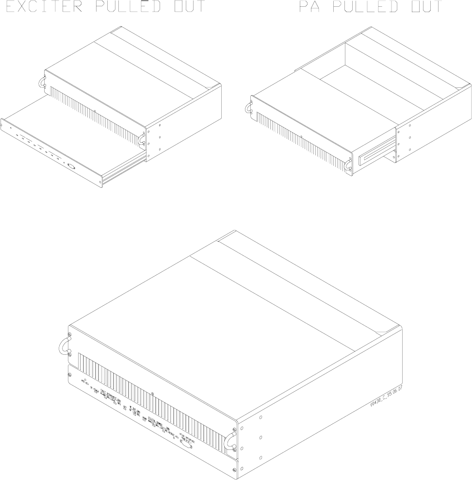
Refer to Figure 3-1, Transmitter Chassis Isometric Front View, which shows a front view
of the PA chassis which is used in all models in this transmitter series. It is virtually impos-
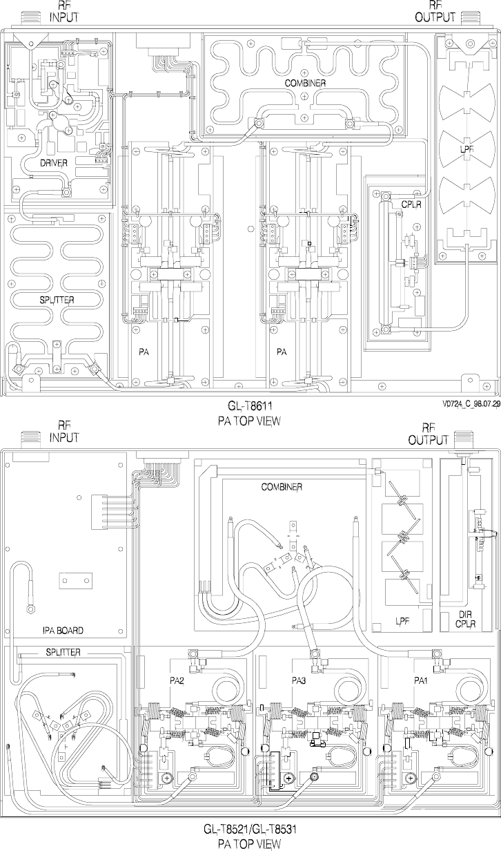
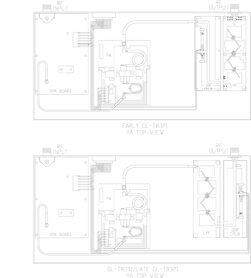
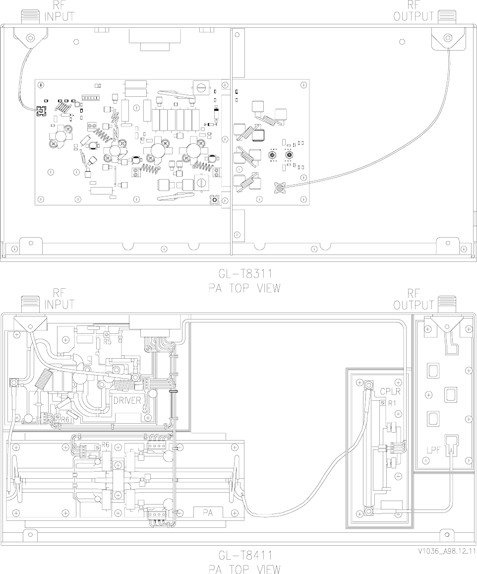
sible to identify the transmitter from the front view; refer to Figure 3-2, Typical PA Top
Views. Positive identification can only be done by removing the PA top cover since each
transmitter has a unique PA compartment.
3.2.1 Mounting Provisions
The transmitter chassis is mounted in the rack by screws which are inserted into the angle
brackets on either side of the chassis. Access to the exciter and PA compartment is gained
from the front; access to the metering board, fans, and I/O connections is gained from the
rear.
3.2.1.1 PA and Exciter Assemblies
The transmitter chassis contains slide-out locations for the following:
• PA RF compartment (2 RU)
• exciter (1 RU)
Rear-mounted fans blow air across the PA heat sink and out the front.
The PA compartment and exciter are mounted on slides which allow them to be accessed
or removed by loosening the knurled thumb fasteners on either side of the assembly. Most
exciter maintenance operations can be performed with the exciter mounted in the rack.
Most PA maintenance can be performed with the transmitter chassis mounted in the rack.
3.2.1.2 Power Supply
The power supply is contained in a separate chassis which is mounted separately from the
transmitter chassis. The power supply may be an ac power supply, which converts 50/60-
Hz mains power to dc voltage for the transmitter, or it may be a dc-to-dc converter. Refer
to the power supply manual for details.
GL-T8xx1 Transmitter System Glenayre Document Number: 9110.00166
DESCRIPTION Revision K: 08/30/99
Page: 3-2 Copyright © 1999 Glenayre
3.2.1.3 Video Display Terminal
A video display terminal (VDT) is not necessarily part of the racked-up equipment; instead, it is a piece of
test equipment which the user brings to the site when setup, maintenance, or troubleshooting is necessary; or
it is used as a monitoring device. Refer to the VDT manual for details, including cable requirements.
g
l
Figure 3-1 Transmitter Chassis Isometric Front View

Glenayre Document Number: 9110.00166 GL-T8xx1 Transmitter System
Revision K: 08/30/99 DESCRIPTION
t523.b94
Copyright © 1999 Glenayre Page: 3-3
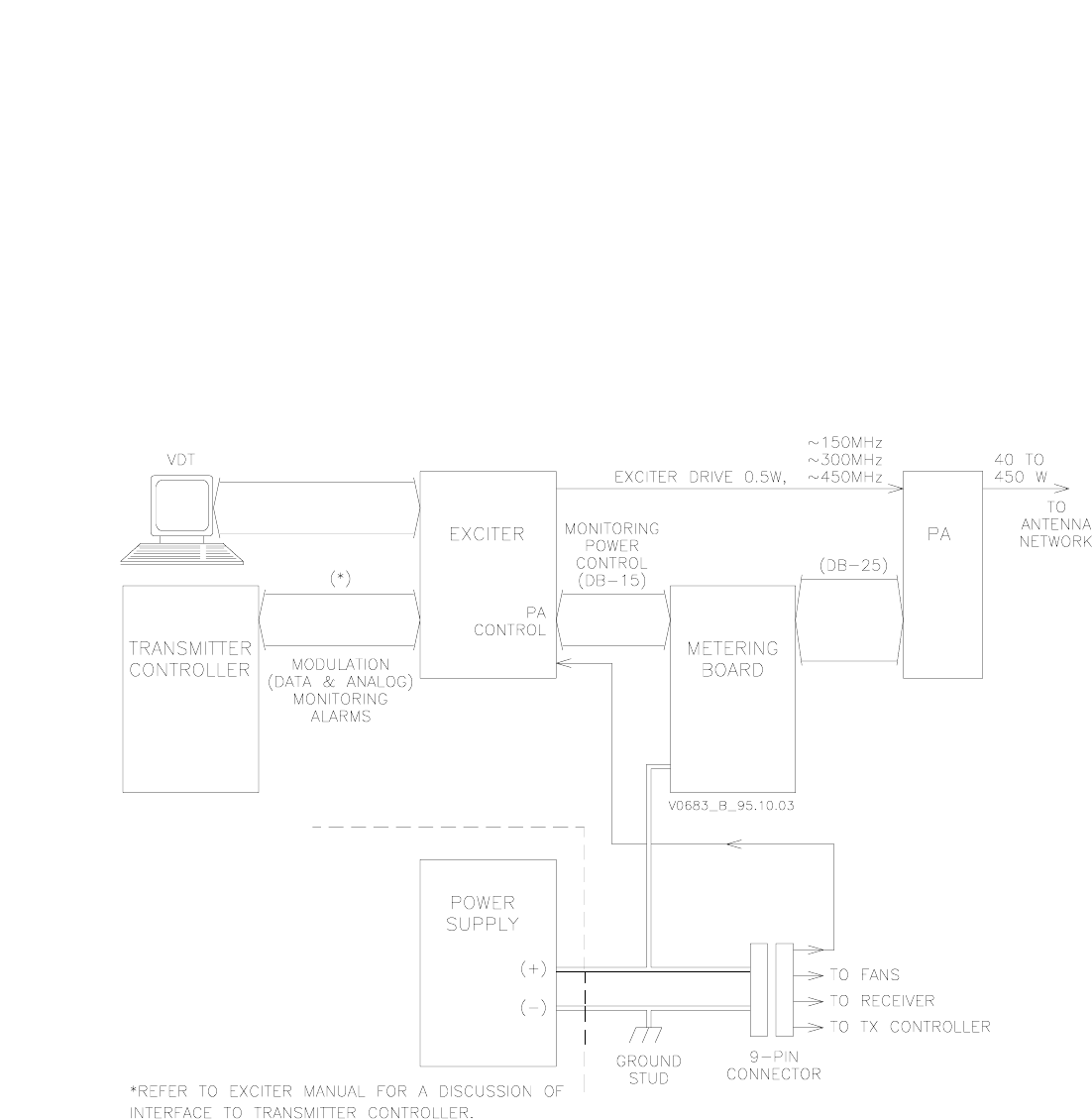
3.3 Simplified Paging-Site Functional Description
3.3.1 Paging Site
The following paragraphs provide a block diagram-level functional description of a typical
paging site.
Refer to Figure 3-3, Transmitter Functional Diagram. This figure shows basic signal flows
between the various paging site equipment pieces. The communications device which the
transmitter uses in order to communicate with the control site is not shown and may vary
from application to application.
3.3.2 Communications Equipment and Transmitter Controller
A link receiver, satellite receiver, microwave drop, telephone link, or other similar device
is used for communication between the transmitter controller and the control site. The
particular device depends on the application.
The transmitter controller is typically a GL-C2000 model. There are various ways of inter-
facing the transmitter controller to the I/O portions of the exciter. Refer to the transmitter
controller manual and the exciter manual for details.
3.3.3 Paging Transmitter
The paging transmitter converts the signal from the transmitter controller into modulated
and amplified RF. Depending on the type of transmitter controller-to-exciter interface
which is used, the modulation information from the transmitter may be audio, modem
signals (analog or digital), or a digitized representation of the original signal. In any case,
all analog signals are ultimately converted to digital form at some point between the paging
terminal and the DSP modulator in the exciter.
Operation is in response to commands from the transmitter controller via the DSP exciter.
The transmitter monitors its functions and reports its status to the VDT via the exciter. The
transmitter controller permits the transmitter to be controlled and monitored from a remote
location. Local control and monitoring is performed through a VT-100 video display
terminal (VDT).
3.3.3.1 DSP Exciter
The DSP exciter combines functions of an RF exciter and a PA controller. The exciter
generates modulation using digital signal processing (DSP) to achieve accurate, stable
modulation that does not vary with time or temperature. The PA-control section monitors
transmitter status signals in the form of fault logic and voltage samples. The microprocessor
in the exciter reports PA status to the transmitter controller, VDT, and the exciter front
panel. If a malfunction occurs, the transmitter enters a reduced operating condition,
depending on the seriousness of the fault. PA control and status monitoring are performed
by the microprocessor, which consolidates control logic from the transmitter controller or
the locally operated VDT. Both the exciter and transmitter controller receive continuous
status reports from the microprocessor. The exciter is the control and status-monitoring
interface between the transmitter and the user.
GL-T8xx1 Transmitter System Glenayre Document Number: 9110.00166
DESCRIPTION Revision K: 08/30/99
Page: 3-4 Copyright © 1999 Glenayre
v0724.hgl
Figure 3-2 Typical PA Top Views

Glenayre Document Number: 9110.00166 GL-T8xx1 Transmitter System
Revision K: 08/30/99 DESCRIPTION
t523.b94
Copyright © 1999 Glenayre Page: 3-7
The exciter provides up to 0.5 watt of RF drive to the PA. A power-reference signal from
the PA is fed back to the exciter, via the metering board, to allow control and monitoring of
output power.
3.3.3.2 Power Amplifier RF Compartment
The PA performs amplification of the RF signal generated by the exciter. The PA amplifies
a nominal 0.5-watt signal to rated power for application to the antenna system. Monitoring
circuitry is on the metering board in the rear compartment of the PA chassis.
3.3.3.3 Metering Board
The metering board provides a rectified dc sample of the PA output to the exciter; the
exciter, in turn, generates a power-control voltage which maintains PA power at the desired
level.
The metering board also returns operational parameters of the PA, which information can
be read by the transmitter controller and the VDT.
The metering board also serves as a distribution point for dc power for other assemblies
within the transmitter chassis.
3.3.3.4 Power Supply
Because different power supplies can be used, refer to the appropriate power supply manual
for details.
3.3.3.4.1 Ac-Powered Sites
The standard ac power supply takes ac input, converts it, rectifies and filters it, and supplies
dc output to all racked equipment. Each dc circuit is individually fused on the front of the
supply. A circuit breaker on the front of the supply doubles as a transmitter power on/off
switch.
3.3.3.4.2 Dc-Powered Sites
Dc-only sites typically have a dc breaker / fuse panel mounted for power control. An
external dc source should meet all pertinent specifications. A racked dc-to-dc converter
needs to have adequate cooling provisions so as not to overheat other racked equipment.
3.3.4 Video Display Terminal
The VDT, though not part of the transmitter, is required for setup, local control, and local
monitoring of the transmitter. The VDT can be any laptop or desktop terminal with a
VT-100 type program. The VDT interfaces the transmitter through the connector on the
front of the exciter. The VDT software is menu-driven.
GL-T8xx1 Transmitter System Glenayre Document Number: 9110.00166
DESCRIPTION Revision K: 08/30/99
Page: 3-8 Copyright © 1999 Glenayre
3.4 Site Signal Flows
3.4.1 Site RF-Signal Flow
The on-frequency carrier is created by the VCO circuitry in the DSP exciter. It is then
modulated with paging information, amplified, and sent to the PA via connector J3 on the
back of the DSP exciter. Through coaxial cable, the carrier goes to the back of the PA,
where it is further amplified to a preset level under control of a microprocessor within the
exciter. The amplified carrier is cabled from the PA output to the antenna system. Note that
some installations have a ten-MHz reference signal cabled from the transmitter controller
to connector J8 on the back of the DSP exciter.
3.4.2 Site Audio-Signal Flow
Modulation information arrives at the site either through a link receiver or by wireline. The
signal can be either analog or digital and is first routed through the transmitter controller,
which checks for and responds to appropriate embedded commands. Paging information is
supplied to the exciter. The exciter modulates this signal using digital signal processing,
then up-converts this modulated signal to final output frequency. This modulated RF from
the exciter is supplied to the PA, which amplifies the signal to the RF output level. This
modulated, amplified RF from the PA is supplied to an antenna network for transmission.
An audio-monitoring speaker is available on the Glenayre RL-XX3-series receiver.
3.4.3 Site Control-Signal Flow
Transmitter paging-site control is done two ways: remotely (normal operation), and locally.
In either case, the paging transmitter is keyed when the transmitter controller commands it,
via the DSP exciter, to key.
Control functions are shared by the transmitter controller and the DSP exciter, which
controls the power amplifier. The DSP exciter also controls the power amplifier locally by
responding to commands from the VDT.
Control signals enter and exit the paging site via the transmitter controller, which has
overall control of the paging site. The transmitter controller is part of the larger paging
control system even though it is racked with paging-site equipment. The transmitter
controller has control functions which include those listed below.
• transmitter alarm gathering
• transmitter alarm dispatching
• simulcast parameter implementation
• remote transmitter operation interface.
Remote control of the paging site is done through commands being sent to the transmitter
controller from the external paging control system.
Control commands originating from a remote site are supplied to the exciter through the
controlling device. Control and setup commands may be applied to the exciter locally
through the VDT. A microprocessor within the exciter interprets each command and
responds by performing the appropriate function.
Glenayre Document Number: 9110.00166 GL-T8xx1 Transmitter System
Revision K: 08/30/99 DESCRIPTION
t523.b94
Copyright © 1999 Glenayre Page: 3-9
3.4.4 Status-Signal Flow
The exciter monitors transmitter status signal in the form of fault logic and voltage samples.
The microprocessor within the exciter reports transmitter status to the controlling device,
VDT, and the exciter front panel. If a transmitter malfunction occurs, a reduced operating
condition is entered, depending on the seriousness of the fault.
v0683.hgl
Figure 3-3 Transmitter Functional Diagram
GL-T8xx1 Transmitter System Glenayre Document Number: 9110.00166
DESCRIPTION Revision K: 08/30/99
Page: 3-10 Copyright © 1999 Glenayre

Glenayre Document Number: 9110.00166 GL-T8xx1 Transmitter System
Revision K: 08/30/99 INSTALLATION AND SETUP
t524.b94
Copyright © 1999 Glenayre Page: 4-1
4 INSTALLATION AND SETUP
4.1 Inspection
Inspect the equipment to be certain that the equipment rack is complete. Compare items
received to the packing list. Report shipping loss or damage to carrier within 15 days of
receipt. Remove any packing material from the rack and check each assembly. Pay partic-
ular attention to the power supply; check it closely and remove any foreign material in the
chassis. Be certain to disconnect primary power from the power supply before removing
any equipment covers.
4.2 Installation
4.2.1 Tools and Equipment Required
Refer to Table 4-1, Tools and Equipment. Equipment listed by brand name may be substi-
tuted with equivalent. For installation, only common hand tools are necessary if at all, since
installation is usually completed at the factory.
4.2.2 Rack Positioning
Cooling and cabling restraints require that equipment pieces be racked so that there is
adequate ventilation for exhaust air. The top and front of the rack should have at least ten
inches of free space. The cabinet should be placed as close as possible to the transmitting
antenna, and to the primary power source as a secondary consideration. To gain reasonable
access to the back, 30 inches of free space should be allowed.
Table 4-1 Tools and Equipment
Device Description
nut driver 5/16 inch
screwdriver # 2 flat blade
screwdriver # 2 Phillips
RF power meter Bird model 4421 or equivalent
dummy load Bird model 8327 or equivalent
barrel connector type-N
RF cable type-N ends, 1m long max
voltmeter Fluke 77 DVM or equivalent

GL-T8xx1 Transmitter System Glenayre Document Number: 9110.00166
INSTALLATION AND SETUP Revision K: 08/30/99
Page: 4-2 Copyright © 1999 Glenayre
Caution
Never place rack where moisture, steam, conden-
sation, or standing water can come in contact with
it. The host room may need to be air conditioned or
additionally ventilated to remove excess heat
generated by this equipment.
4.2.3 Rack Grounding
The rack cabinet must be connected to a reliable earth ground. Connect the earth ground
point to the ground stud provided in the bottom of the cabinet; use four-gauge or larger
copper conductor.
4.2.4 Positioning within the Rack
When it is used in a normal, one-transmitter-per-cabinet rackup, the transmitter chassis
should be placed just above the power supply.
The transmitter is normally shipped already installed in a cabinet. To remove or reinstall
the transmitter chassis, refer to Section 9.
4.2.5 Primary Power Requirements
The primary power source must be capable of delivering adequate power to the equipment.
Racked power supplies operate with 60-Hz ac unless the power supply has the 50-Hz option
or is dc-only. Refer to Section 2 of this manual and to the power supply manual for current
and voltage specifications. Electrical connections made to this equipment must be made in
accordance with local electrical codes.
DANGER
Rotating fan blades are a hazard to maintenance
personnel who access equipment from the rear.
Caution
The rear door must be closed and the fans must be
operating before the PA is keyed to ensure that the
PA receives adequate ventilation.

Glenayre Document Number: 9110.00166 GL-T8xx1 Transmitter System
Revision K: 08/30/99 INSTALLATION AND SETUP
t524.b94
Copyright © 1999 Glenayre Page: 4-3
4.2.5.1 Special Considerations
Various options for the power supply permit operation at different line frequencies and
voltages. The supplied connector allows for these variations. If the supplied connector is
not used, be certain that the correct combination of line frequency and voltage is applied.
The power supply causes a large inrush of current when first turned on. The ac supply
breaker must be able to handle this brief surge.
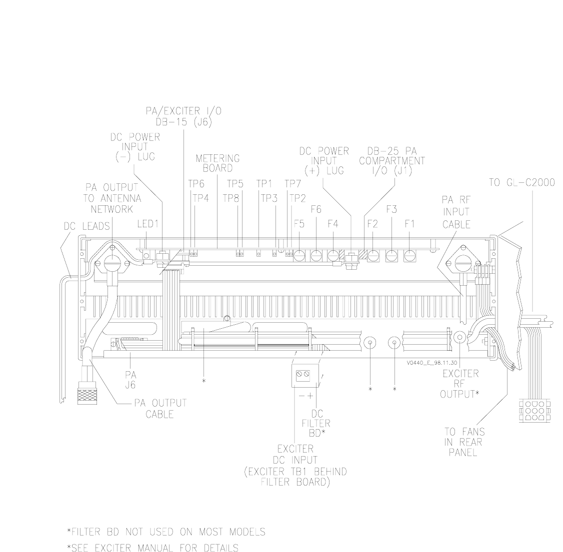
4.2.6 Equipment Cabling
Refer to Figure 4-1, Transmitter Rear View with Door Open and Figure 4-2, Transmitter
Chassis Pictorialized Schematic for details.
4.2.6.1 Ac Connections
Generally, all ac connections internal to the rack are made at the factory and should not need
to be modified. Refer to the power supply manual for additional details.
4.2.6.2 Dc Connections
If cable is being originally installed or replaced, be sure connections are sufficiently tight.
Refer to the power supply and related manuals for details.
4.2.6.3 Dc-Only Sites
Some installation do not use ac input power. If the transmitter is not racked and wired at the
factory, be sure to connect as shown in the documentation supplied with the retrofit option.
Note
For locations operating from a direct 28 Vdc source or an external power
supply, the dc supply cable must not exceed three meters (3 m) in length.
This restriction is critical to comply with the emission and immunity
requirements
4.2.7 PA Chassis Connections
Refer to Table 4-2, PA Chassis Connectors. As viewed from the back, RF input is on the
right; RF output is on the left; the power/IO connector is in the middle.
Table 4-2 PA Chassis Connectors
Connector Description /Function
PA RF INPUT type-N, quick-connect/ RF from exciter to PA unit
PA RF OUTPUT type-N, quick-connect/ RF from PA to antenna
POWER/IO J1 DB-25, quick-connect/ power for... and I/O to and from, PA boards

GL-T8xx1 Transmitter System Glenayre Document Number: 9110.00166
INSTALLATION AND SETUP Revision K: 08/30/99
Page: 4-4 Copyright © 1999 Glenayre
4.2.8 Metering Board Connections
Refer to Table 4-2, PA Chassis Connectors. As viewed from the back, the + dc lug is on the
right; the - dc lug is on the left; the control/ IO connector is in the middle.
Table 4-4, Exciter J6-to-Metering Board DB-15 J6 Pin Functions, shows the functional
pinout of the connection between the metering board and the DSP exciter.Table 4-7, Detail
of J1 Connections (DB-25) between Metering Board and PA RF Compartment, shows the
functional pinout of the connection between the metering board and the PA compartment.
Note that the connection is made whenever the PA compartment is positioned normally
within the transmitter compartment, as the connector on the metering board becomes effec-
tively, part of the chassis.
Table 4-3 Metering Board Connectors
Connector Description /Function
+ dc lug 1/4 -20 post, part of metering bd assembly/ main dc supply input
- dc lug 1/4 -20 post, part of metering bd assembly/ dc supply ground
control/IO J2 DB-15, part of metering bd assembly/ control and IO
Glenayre Document Number: 9110.00166 GL-T8xx1 Transmitter System
Revision K: 08/30/99 INSTALLATION AND SETUP
t524.b94
Copyright © 1999 Glenayre Page: 4-5
v0440.hgl
Figure 4-1 Transmitter Rear View with Door Open
GL-T8xx1 Transmitter System Glenayre Document Number: 9110.00166
INSTALLATION AND SETUP Revision K: 08/30/99
Page: 4-6 Copyright © 1999 Glenayre
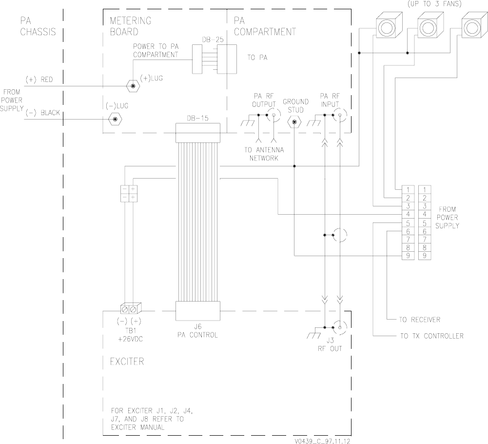
v0439.hgl
Figure 4-2 Transmitter Chassis Pictorialized Schematic
RF input is physically
on the left (as viewed
from rear).

Glenayre Document Number: 9110.00166 GL-T8xx1 Transmitter System
Revision K: 08/30/99 INSTALLATION AND SETUP
t524.b94
Copyright © 1999 Glenayre Page: 4-7
4.2.9 System Connectors
Refer to the transmitter controller manual for additional system connections at the paging-
transmitter site.
4.2.10 I20 Control
GL-C2000 controllers (265-0090-002) manufactured prior to October, 1994, must have the
universal exciter ASM board (265-0090-008) and v2.3 or later software installed. Units
built after the October 1994 date support the I20 interface and have an assembly rev of A2
or greater (e.g., A2, B1, C1, etc.)
4.3 Setup
Refer to Table 4-6 and Table 4-6 for jumper setups for various transmitters.
Table 4-4 Exciter J6-to-Metering Board DB-15 J6 Pin Functions
DSP
J6- Exciter Function
Metering
Board
J6- Metering Board Function
1 multiplex analog input from PA No. 1 multiplexer 1 A/D1
2 multiplex analog input from PA No. 3 multiplexer 2 A/D3, fixed LO
3 AGC reference voltage output to PA, 1-12 Vdc 3 AGC ref
4 no connection 4 ground
5 no connection 5 ground
6 1 of 4 select outputs to PA multiplexers, LO=216 input sel 2
7 one of four select outputs to PA multiplexers, not used 7 PA key input, enables AGC and preamplifier stage
8ref sample
9 multiplex analog input from PA No. 2 multiplexer 9 A/D2
10 multiplexed analog input from PA No. 4 multiplexer 10 A/D4, fixed LO
11 PA fault input, LO=fault fixed LO (active logic in some versions)
12 no connection ground
13 one of four select outputs to PA multiplexers, LO=20
digit enabled for mux input decoder 13 input sel 1
14 one of four select outputs to PA multiplexers, LO=22
digit enabled for mux input decoder 14 input sel 3
15 latch-enable output to PA multiplexers, LO=mux input
decoder reads the three select inputs 15 spare

GL-T8xx1 Transmitter System Glenayre Document Number: 9110.00166
INSTALLATION AND SETUP Revision K: 08/30/99
Page: 4-8 Copyright © 1999 Glenayre
Table 4-5 Metering Board Jumper Table for Transmitter Setups (w/ assembly 2000.00116)
JW1 JW2 JW3 JW4 JW5 JW6
GL-T8331
GL-T8321
GL-T8521
AAB B B A
GL-T8531 A A B B B B
Table 4-6 Metering Board Jumper Table for Transmitter Setups (w/ assembly 2000.00513)
JW1 JW2 JW3 JW4 JW5 JW6
GL-T8311 B A A A B A
GL-T8411
GL-T8611 B
AB
BA
AA
AB
BB
B

Glenayre Document Number: 9110.00166 GL-T8xx1 Transmitter System
Revision K: 08/30/99 INSTALLATION AND SETUP
t524.b94
Copyright © 1999 Glenayre Page: 4-9
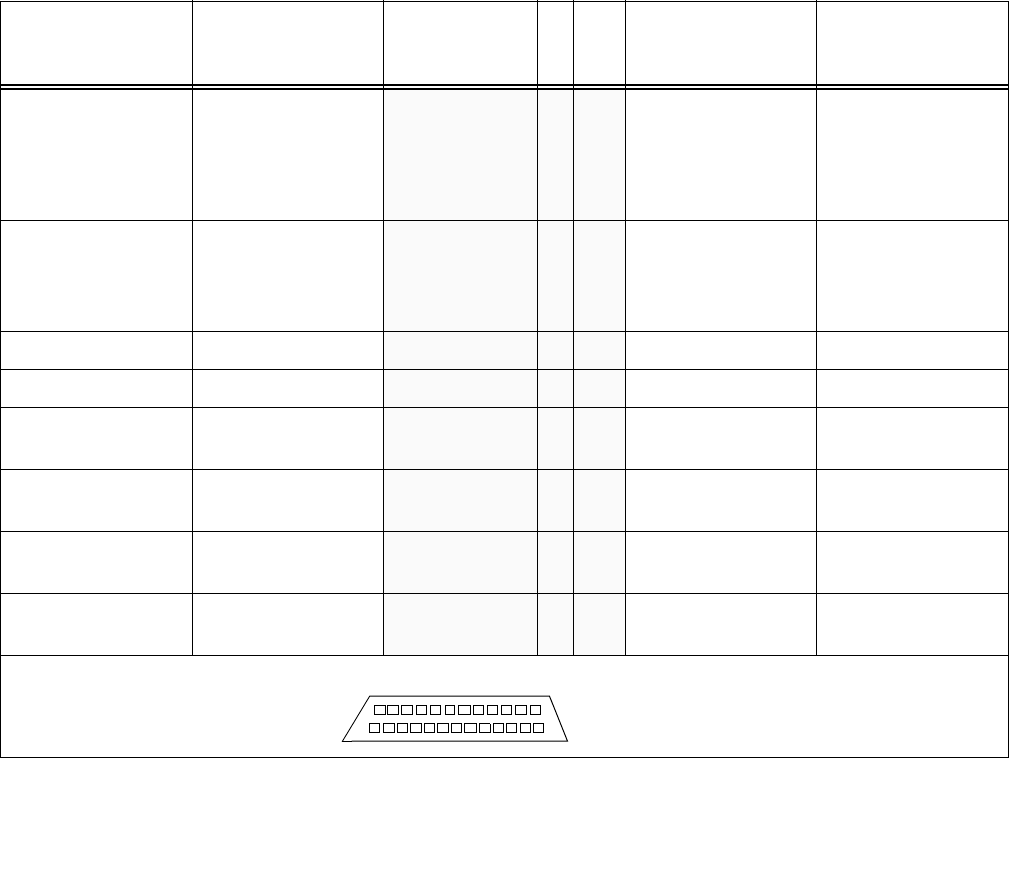
Table 4-7 Detail of J1 Connections (DB-25) between
Metering Board and PA RF Compartment
8521/8531 PA RF
compartment
function
8321/8331 PA RF
compartment
function m b function
J1
-
Xm b
fuse
8311/ 8411 PA RF
compartment
function
8611 PA RF
compartment
function
A2P1-5, PA (nearest
to IPA) current A2P1-5, PA current PA2-A, PA2, PA 1F4 PA2-J1 supply current
A2P1-6, PA (nearest
to IPA) current A2P1-6, PA current PA2-A, PA2, PA 2F4 PA2-J1 supply current
PA2-B 3F6 PA2-J2 supply current
PA2-B 4F6 PA2-J2 supply current
A5 REF, sample re-
flected dc relative
output
A3 REF, sample re-
flected dc relative out-
put
REF PWR, dc
sample of
reflected power
5P6-1, reflected power
sample from direc-
tional coupler board
(red wire)
P6-1, reflected power
sample from direc-
tional coupler board
(red wire)
A5 FWD, sample for-
ward dc relative
output
A3 FWD, sample for-
ward dc relative
output
FWD PWR, dc
sample of
forward power
6P6-4, forward power
sample from direc-
tional coupler (black
wire)
P6-4, forward power
sample from direc-
tional coupler (black
wire)
A1P1-2, key signal
for first IPA stage A1AP3-2, key signal
for first IPA stage PREAMP KEY 7P1-1, preamp key bus P1-1, preamp key bus
A1P1-6, temperature
sensor on IPA board A1AP3-6, tempera-
ture sensor on IPA
board
TEMP SENSOR 8P1-4, temp sensor on
driver board P1-4, temp sensor on
driver board
DRIVER+ 9F1 P1-3, +supply to driv-
er P1-3, +supply to
driver
A4P1-5, PA (farthest
from IPA) current PA1-A, PA1 10 F2 P4-1, +supply to PA
board P4-1, +supply to PA
board
A4P1-6, PA (farthest
from IPA) current PA1-A, PA1 11 F2 P4-2, +supply to PA
board P4-2, +supply to PA
board
A3P1-, PA (center)
current PA1-B, PA3 12 F3 P5-8, +supply to PA
board P5-8, +supply to PA
board
A3P1-6, PA (center)
current PA1-B, PA3 13 F3 P5-2, +supply to PA
board P5-2, +supply to PA
board
A2P1-7, PA (nearest
to IPA) current A2P1-7, PA current PA2-A, PA2 14 F4 PA2-J1 supply current
A2P1-8, PA (nearest
to IPA) current A2P1-8, PA current PA2-A, PA2 15 F4 PA2-J1 supply current
PA2-B 16 F6 PA2-J2 supply current
PA2-B 17 F6 PA2-J2 supply current
GL-T8xx1 Transmitter System Glenayre Document Number: 9110.00166
INSTALLATION AND SETUP Revision K: 08/30/99
Page: 4-10 Copyright © 1999 Glenayre
4.4 Ultimate Disposition
Caution
This equipment may contain hazardous materials.
Check with the local EPA or other environmental
authority before disposing of this equipment.
A4P1-1, (daisy-
chained to A3P1-1,
A2P1-1, A1P1-3) -
15-Vdc bias current
for 3 PAs
A2P1-1, (daisy-
chained to
A1A3P1-3), -15-Vdc
bias current for IPA
and PA
-15V 18 P3-1, -15 Vdc to PA
board (daisy-chained
to P2-4 on driver
board)
P3-1, -15 Vdc to PA
board (daisy-chained
to P2-4 on driver
board)
A4P1-3 (daisy-
chained to A3P1-3,
A2P1-3), AGC volt-
age
A2P1-3, AGC voltage AGC 19 P3-4, AGC to PA
board P3-4, AGC to PA
board
A1P1-1, IPA current A1AP3-1, IPA current DRIVER+ 20 F1 PRE KEY BUS PRE KEY BUS
A1P1-4, IPA current A1AP3-4, IPA current DRIVER+ 21 F1 PREAMP PREAMP
A4P1-7, PA (farthest
from IPA) current PA1-A, PA1 22 F2 P4-3, +supply to PA
board P4-3, +supply to PA
board
A4P1-8, PA (farthest
from IPA) current PA1-A, PA1 23 F2 P4-4, +supply to PA
board P4-4, +supply to PA
board
A3P1-7, PA (center)
current PA1-B, PA3 24 F3 P5-3, +supply to PA
board P5-3, +supply to PA
board
A3P1-8, PA (center)
current PA1-B, PA3 25 F3 P5-4, +supply to PA
board P5-4, +supply to PA
board
DB-25 connector, as viewed from front (inside of PA compartment)
Table 4-7 Detail of J1 Connections (DB-25) between
Metering Board and PA RF Compartment (continued)
8521/8531 PA RF
compartment
function
8321/8331 PA RF
compartment
function m b function
J1
-
Xm b
fuse
8311/ 8411 PA RF
compartment
function
8611 PA RF
compartment
function
113
14
25

Glenayre Document Number: 9110.00166 GL-T8xx1 Transmitter System
Revision K: 08/30/99 OPERATION
t525.b94
Copyright © 1999 Glenayre Page: 5-1
5OPERATION
5.1 Controls and Indicators
These assemblies within the transmitter chassis have controls and indicators:
• PA compartment - see PA manual
• exciter - see exciter manual
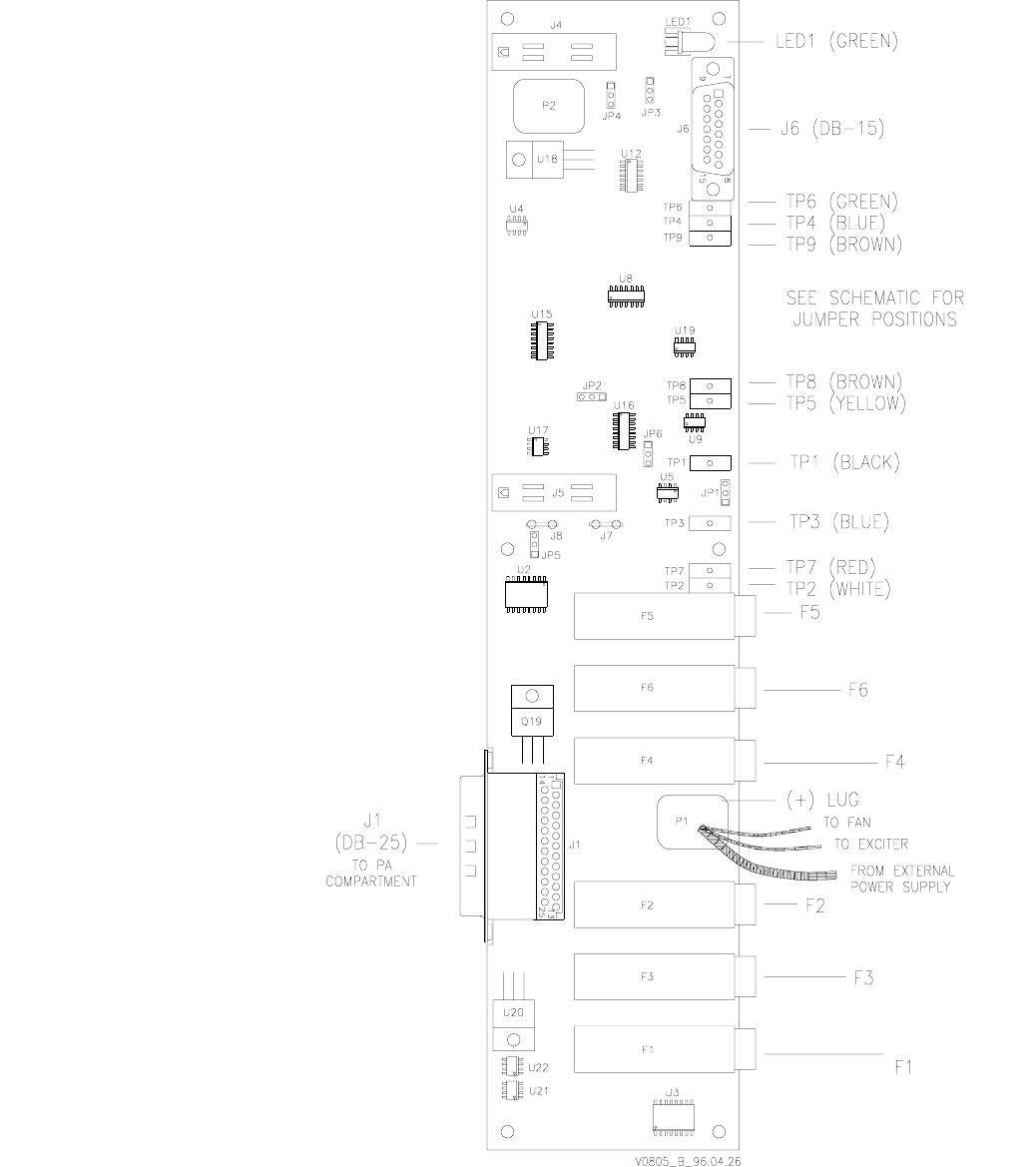
• metering boards - (Figure 5-1, and Figure 5-2).
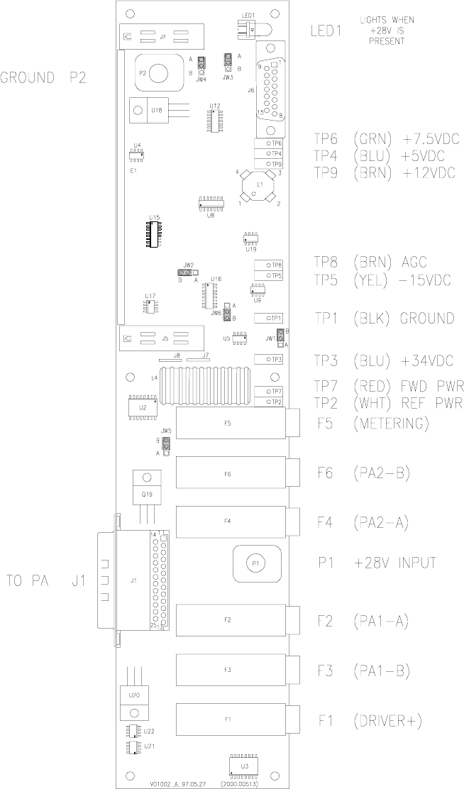
Metering board assembly 2000.00116 is used in GL-T8321, 8331, 8521, and 8531 trans-
mitter models. Assembly 2000.00513 is used is GL-T8311, 8411, and 8611 transmitter
models.
Also see Table 5-1 for more information.
5.2 Operation
The transmitter normally operates within the paging system in an unattended manner. Local
control is not intended for operation, but for setup, checkout, or maintenance. On the
metering board, LED1 lights when 28 Vdc is applied to it. No controls are available.
5.2.1 Turn PA On and Off
The PA does not contain an on/off switch, but turns on and off whenever the primary power
equipment is turned on and off. When the PA is on, it remains in a standby condition until
keyed. Turning off primary power (ac or dc) always turns off the transmitter (PA and
exciter).
5.2.2 Fan(s) Control
The fan(s) are thermostatically-controlled. Fan speed can vary depending on PA loading.
The fan(s) do not contain an on/off switch, but turn on and off whenever the primary power
equipment is turned on and off. The fan(s) run continuously whenever primary power is on.
Jumper JW5 on the metering board is used to enable or disable variable fan speed control.
When it is set to position B, fan speed control is disabled and the fans run full speed at all
temperatures. When it is set to position A, fan speed control is enabled.
DANGER
Rotating fan blades are a hazard to maintenance
personnel who access equipment from the rear.

GL-T8xx1 Transmitter System Glenayre Document Number: 9110.00166
OPERATION Revision K: 08/30/99
Page: 5-2 Copyright © 1999 Glenayre
Caution
The rear door must be closed and the fans must be
operating before the PA is keyed in order to ensure
that the PA receives adequate ventilation.
5.2.3 Key and Unkey PA
The PA does not contain a key switch, but is keyed and unkeyed by the exciter. The exciter
must be keyed and unkeyed remotely through transmitter controller or locally through a
video display terminal (VDT). Refer to the controller manual for remote key and unkey
instructions or to the VDT manual for local key and unkey instructions.
Table 5-1 Metering Board Fuses, Indicators, and Test Points
Control/
Indicator Function Control/
Indicator Function
F1* driver fuse The function of fuses
varies, depending on the
PA used. To match a
fuse with the affected
PA function, refer to
Table 4-7.
TP1
(black)
GROUND, ground
F2* PA1-A, PA1 fuse TP2
(white)
REF, indication of reflected power
F3* PA1-B, PA3 fuse TP3
(blue) +34 Vdc
F4* PA2-A, PA2 fuse TP4
(blue) +5 Vdc
F5* metering-board circuitry
fuse TP5
(yellow) -15 Vdc
F6* PA2-B fuse TP6
(green) +7.5 Vdc
TP7
(red)
FWD, indication of forward power
LED1
(green)
POWER, indicates +26-Vdc
input power applied TP8
(brown)
AGC, sample of AGC voltage to PA com-
partment (controlled by forward-power and
AGC ref, subject to shutdown circuit)
______________
*Replace fuses with fuses of the same current rating. F1 through F4 and F6 are 20 A; F5 is 1 A.

Glenayre Document Number: 9110.00166 GL-T8xx1 Transmitter System
Revision K: 08/30/99 THEORY OF OPERATION
t526.b94
Copyright © 1999 Glenayre Page: 6-1
6 THEORY OF OPERATION
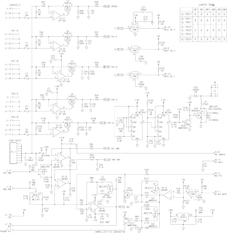
6.1 Metering Board
Refer to Figure 6-1 and Figure 6-2 for detailed circuit information.
6.1.1 Dc-Power Distribution
The +lug on the metering board is the main distribution point for dc power within the trans-
mitter chassis. The following connections terminate at the +lug:
• dc power from main power supply
• dc power to rear-mounted fans
• dc power to exciter
• dc power to PA compartment (through pc traces on board)
There are several current sources for stages within the PA compartment. Each separate
circuit contains a fuse, metering resistor, and associated circuitry for measuring and
reporting circuit currents. Table 5-1, Metering Board Fuses, Indicators, and Test Points,
shows the circuits which are protected by the various fuses. Note that some transmitters do
not use every fused circuit. Table 4-7, Detail of J1 Connections (DB-25) between Metering
Board and PA RF Compartment, shows the functions of the connections between the
metering board and the PA compartment.Table 4-4, Exciter J6-to-Metering Board DB-15
J6 Pin Functions, shows detail of the connections between the metering board and the
exciter.
6.1.2 Control-Signal Distribution
6.1.2.1 Transmitter Keying
The transmitter may be keyed remotely by the transmitter controller or locally by the VDT.
The exciter receives the key signal and activates internal circuitry which causes its RF
output to become active. The exciter also sends a key signal to the PA RF compartment.
The exciter signal is wired to metering-board J6-7. Metering-board circuitry relays the
signal to the PA RF compartment and the IPA second amplifier stage via J1-7. The AGC
reference signal from the exciter is passed to metering-board circuitry when the key signal
is active.
6.1.2.2 Power-Output Control
A reference signal from the exciter determines the nominal output power. Depending on the
exciter interface, the level may be remotely adjustable. The REF PWR dc reference signal
(J1-5 and J6-8) is also routed to the exciter for use in determining acceptable output power
and for generating alarms.
GL-T8xx1 Transmitter System Glenayre Document Number: 9110.00166
THEORY OF OPERATION Revision K: 08/30/99
Page: 6-2 Copyright © 1999 Glenayre
vv0806.hgl
Figure 6-1 Metering Board 2000.00116 Functional Diagram
Glenayre Document Number: 9110.00166 GL-T8xx1 Transmitter System
Revision K: 08/30/99 THEORY OF OPERATION
t526.b94
Copyright © 1999 Glenayre Page: 6-3
v0807.hgl
Figure 6-1, Metering Board Functional Diagram (continued)
GL-T8xx1 Transmitter System Glenayre Document Number: 9110.00166
THEORY OF OPERATION Revision K: 08/30/99
Page: 6-4 Copyright © 1999 Glenayre
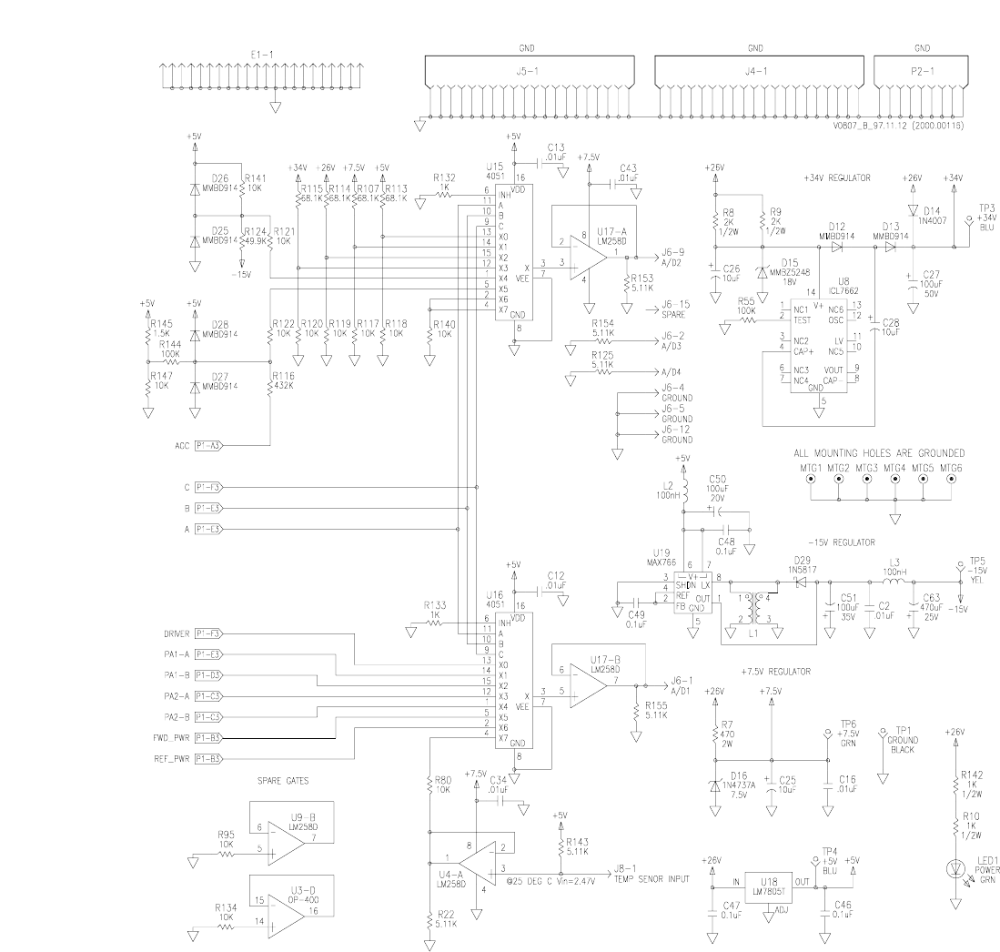
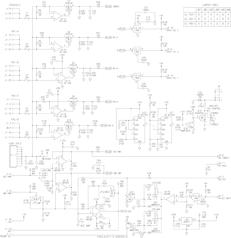
Figure 6-2 Metering Board 2000.00513 Functional Diagram
Glenayre Document Number: 9110.00166 GL-T8xx1 Transmitter System
Revision K: 08/30/99 THEORY OF OPERATION
t526.b94
Copyright © 1999 Glenayre Page: 6-5
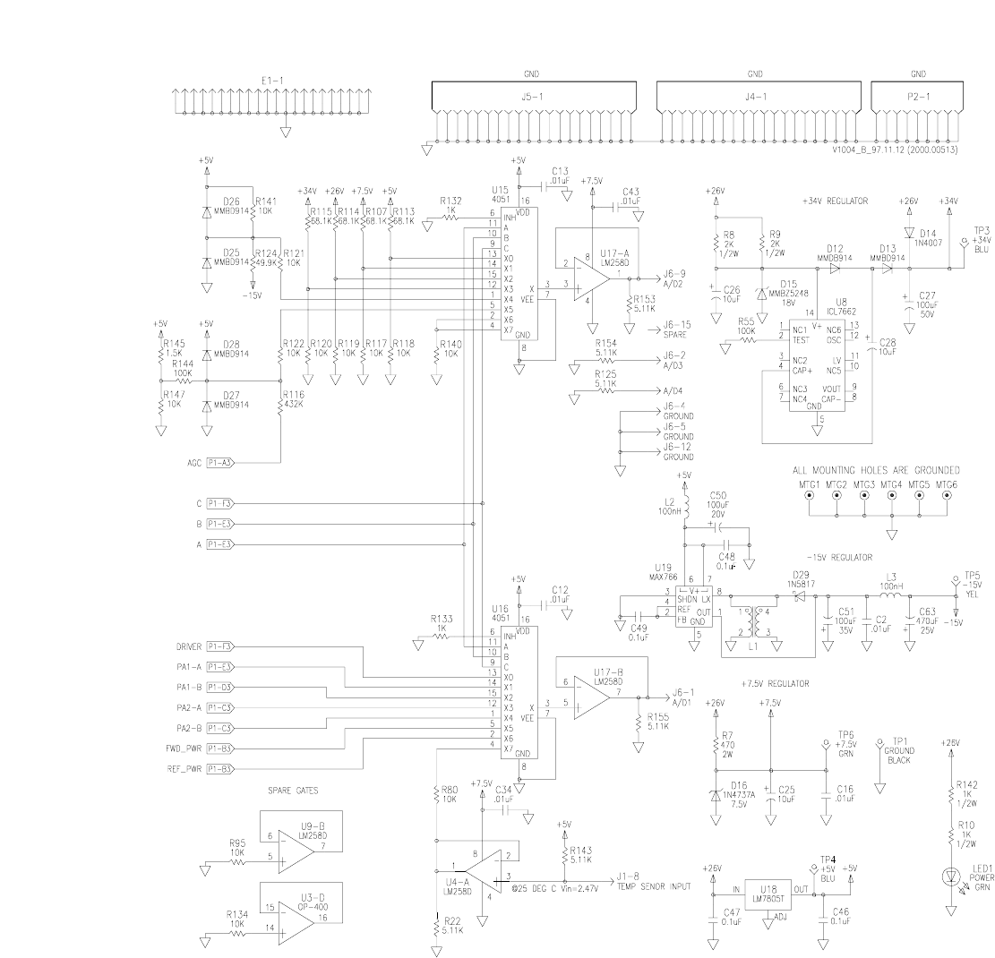
Figure 6-2 Metering Board 2000.00513 Functional Diagram (continued)

GL-T8xx1 Transmitter System Glenayre Document Number: 9110.00166
THEORY OF OPERATION Revision K: 08/30/99
Page: 6-6 Copyright © 1999 Glenayre
The metering board compares the AGC REF signal (J6-3) from the exciter and the FWD
PWR dc reference signal (J1-6) from the PA RF compartment. The metering board attempts
to hold power constant by using these signals to generate the AGC voltage (J1-19) which
it sends to the PA RF compartment. All stages, except the first IPA stage, are under the
influence of the AGC signal.
6.1.2.3 Signal Measurement and Alarm Gathering
Refer to Table 4-7, Detail of J1 Connections (DB-25) between Metering Board and PA RF
Compartment. Each PA board and IPA board have separate, fused supplies, whose currents
are measured by A/D converters which are multiplexed to the A/D1 line (J6-1) and A/D2
line (J6-9) to the exciter. The exciter has three input-select lines which determine the circuit
to be measured. Refer to Table 6-1, Input-Select Metering Lines from Exciter.
Several metering points may not be used depending on the metering board assembly and
the transmitter it is in. The labels of the measured parameters appear on the VDT screen
when it is used to measure operating parameters. Refer to the VDT manual for details.
6.1.2.4 PA Fault
On nearly all versions of the metering board, no hardware circuit for PA-fault detection is
installed, and PA faults are determined by software, as power supply voltage, PA currents,
and RF power output can be read by the software.
On a few versions of the metering board, there is a hardware fault-detection circuit. If any
of the PAs experiences a fuse-blowing fault, the PA FAULT line (J6-11) becomes active
(HI).
Table 6-1 Input-Select Metering Lines from Exciter
input-select line J6-x pin
113
26
314

Glenayre Document Number: 9110.00166 GL-T8xx1 Transmitter System
Revision K: 08/30/99 MAINTENANCE
t527.b94
Copyright © 1999 Glenayre Page: 7-1
7 MAINTENANCE
7.1 General
Little or no maintenance is required on a regular schedule. The following, however, are
important to ensure long term trouble free operation.
Maintenance procedures in this section are listed below:
• PA-current check
• Dc-ripple check.
7.2 PA-Current Check
Occasionally, the power amplifier device currents should be compared to the levels listed
on the data sheet that accompanied the transmitter. Be sure that the operating RF output is
the same as listed on the data sheet. The labelling of PA currents on the VDT’s screen may
be confusing. To relate the VDT indication to a particular pc assembly in the PA RF
compartment, refer to the ‘metering board function’ column of Table 4-7, Detail of J1
Connections (DB-25) between Metering Board and PA RF Compartment. Also refer to the
PA manual for the model of transmitter you are using.
1. Put transmitter in local mode.
2. Key transmitter.
3. Monitor power amplifier currents on VDT.
4. Make comparison between data sheet and monitor.
Monitored currents should not vary more than ten percent from data sheet levels. An
exception is when original components or modules have been replaced or modified; in this
case, a new benchmark should be noted for future reference.
GL-T8xx1 Transmitter System Glenayre Document Number: 9110.00166
MAINTENANCE Revision K: 08/30/99
Page: 7-2 Copyright © 1999 Glenayre
7.3 Dc-Ripple Check
This procedure assumes that an ac power supply is part of the configuration. Occasionally
the ac supply should be checked for excessive ripple. Maximum allowable ripple is given
in section two of this manual. The supply should be under normal operating load for this
procedure.
1. Put transmitter in local mode.
2. Key transmitter.
3. Connect oscilloscope between ground and supply output.
4. Set oscilloscope to read ripple.
The observed ripple level should be less than the ripple specification given in Table 2-1,
Specifications.

Glenayre Document Number: 9110.00166 GL-T8xx1 Transmitter System
Revision K: 08/30/99 CHECKOUT
t528.b94
Copyright © 1999 Glenayre Page: 8-1
8 CHECKOUT
8.1 General
Checkout procedures can be performed at any time to verify that the transmitter and related
paging site equipment is functioning properly. After checkout procedures are successfully
completed, the site can be returned to normal service. Refer to the VDT user manual for
details on checkout procedures.
8.2 Checkout Procedures
8.2.1 Dc-Voltage Verification
Once powered, verify that the equipment is powered and refer to list below.
1. On GL exciter front panel, the DC POWER indicator is on.
2. On the transmitter controller, the POWER indicator is on.
3. On receiver, the POWER indicator is on
GL-T8xx1 Transmitter System Glenayre Document Number: 9110.00166
CHECKOUT Revision K: 08/30/99
Page: 8-2 Copyright © 1999 Glenayre
8.2.2 VDT Power-up Verification
Once powered, verify that the VDT is powered; continue with the checklist below.
1. The VDT should have a cursor displayed and blinking; or,
2. the VDT should have an instructional prompt displayed; or,
3. the VDT should have an auto-loaded program running.
8.2.3 Cooling-Fans Check
Once the transmitter is powered, verify that the fans are operating; they should operate
whenever the transmitter is powered.

Glenayre Document Number: 9110.00166 GL-T8xx1 Transmitter System
Revision K: 08/30/99 REMOVAL AND REINSTALLATION
t529.b94
Copyright © 1999 Glenayre Page: 9-1
9 REMOVAL AND REINSTALLATION
The following paragraphs discuss removing and reinstalling the various assemblies which
make up the transmitter.
Caution
Remove all input power to the cabinet before
performing a removal or reinstallation procedure.
Note
The user may choose to remove the PA and exciter before removing the
transmitter chassis in order to lighten the chassis for handling.
9.1 Transmitter Chassis
The transmitter chassis is held in the equipment rack by screws which are accessible from
the front.
Removal
1. Turn thumbscrew to unlock rear door, and open rear compartment.
2. Remove large black wire from - lug on metering board.
3. Remove large red wire from + lug on metering board.
4. Mark and remove I/O connections between transmitter controller and exciter.
5. Mark and remove coax connection to antenna network.
6. Remove screws from front of rack and pull out transmitter chassis.
Reinstallation
7. Replace chassis in rack; secure with same hardware that was removed.
8. Carefully reinsert exciter and PA units in chassis.
9. Reconnect coax, power leads, and I/O as before.
10. Return transmitter to service.
9.2 Power Supply
Refer to the power supply manual for information.
9.3 PA RF Compartment
Note
Before removing the PA RF compartment, be certain that the fault is on
an assembly within it. The exciter, metering board, and interconnecting
wiring are essential to proper operation of the power amplifier.
GL-T8xx1 Transmitter System Glenayre Document Number: 9110.00166
REMOVAL AND REINSTALLATION Revision K: 08/30/99
Page: 9-2 Copyright © 1999 Glenayre
Removal
1. From front of chassis, turn fasteners ccw so that front panel is loose, and pull PA RF
compartment forward and out of transmitter chassis.
Reinstallation
2. Slide replacement PA RF compartment into location in top of transmitter chassis.
Note that RF connectors slide into receptacles in rear of transmitter chassis.
3. Refasten front-panel fasteners.
Refer to the VDT manual to check out the replacement PA.
9.4 Exciter Removal and Reinstallation
The exciter is installed on slides in the lower third of the chassis. The local reference oscil-
lator, if used, can be adjusted while the unit is mounted in the rack.
Removal
1. From rear or transmitter chassis, label and remove signal connectors on rear of
exciter. Note that some DB-style connectors require loosening screws which hold
mating receptacles in contact with one another.
2. Remove red (+) and black (-) wire from dc filter board by loosening retaining screws.
Tape exposed end of red wire so that it does not come in contact with chassis.
3. Unfasten BNC RF output plug on right side of chassis.
4. Label and remove any other connections to exciter.
5. On chassis front, turn thumb fasteners ccw approximately one quarter turn to loosen;
pull exciter chassis forward and out of transmitter chassis.
Reinstallation
When replacing the exciter, be certain that all variable subassemblies in the replacement
exciter are correct for system requirements. Subassemblies which must be matched include
those included in the list below.
• VCO/RF amplifier (must be for the correct frequency band)
• firmware chips (must be of the correct revision and type)
• controller interface (must be of the proper type and revision for interfacing with trans-
mitter controller).
Refer to the exciter manual for additional information.
1. If necessary, attach dc filter board to dc input of replacement exciter before installing
exciter into transmitter chassis.
2. Slide replacement exciter into location in lower third of transmitter chassis.
3. Refasten front-panel thumb fasteners.
4. Reattach and resecure connectors removed during removal process.
Refer to exciter manual and VDT manual to check out and realign replacement exciter.

Glenayre Document Number: 9110.00166 GL-T8xx1 Transmitter System
Revision K: 08/30/99 REMOVAL AND REINSTALLATION
t529.b94
Copyright © 1999 Glenayre Page: 9-3
9.5 Metering Board Removal and Reinstallation
The fuses on the metering board can be replaced without the need to remove the pc board
from the chassis. In the event that replacing the metering board becomes necessary, use the
following procedures.
Caution
Use static-handling precautions on metering
board.
Removal
1. Mark and remove wires attached to +lug: main dc input, exciter power, fan power.
2. Disconnect DB-15 ribbon cable from exciter.
3. Mounting hardware must be removed from pc board. Use L-shaped Phillips
screwdriver or stubby screwdriver to gain access to screw heads. Alternately, remove
entire metal mounting panel. Remove all screws holding metering board to top of
transmitter chassis.
4. Once screws are removed, remove pc board from chassis by carefully pulling it
toward rear, carefully breaking DB-25 connection to PA RF compartment.
Reinstallation
1. Plug replacement metering-board DB-25 connector into PA RF compartment chassis
receptacle.
2. Reinstall screws removed during removal process. Do not tighten yet.
3. Once all screws are installed, tighten screws.
4. As a test, pull out and replace PA RF compartment shelf to verify that PA RF com-
partment DB-25 chassis receptacle easily docks with metering board.
5. Reconnect DB-15 ribbon cable from exciter.
6. Reconnect power wires to +lug.
The replacement metering board should not require realignment.

GL-T8xx1 Transmitter System Glenayre Document Number: 9110.00166
REMOVAL AND REINSTALLATION Revision K: 08/30/99
Page: 9-4 Copyright © 1999 Glenayre
9.6 Fan Removal and Reinstallation
Heed all cautions at the beginning of this section.
Removal
Before replacing a fan suspected to be defective, determine that it has operating voltage
supplied to it. Remove power to cabinet before beginning procedure.
1. Mark and remove power wires to fan.
2. Remove hardware which holds fan to rear panel.
3. Keep hardware for reinstallation.
Reinstallation
Check fan orientation before installing.
1. Mount fan to panel using removed hardware.
2. Reconnect power connector to fan connector.
3. Secure hardware.
Note
Overtightening of screws may cause fan failure.

Glenayre Document Number: 9110.00166 GL-T8xx1 Transmitter System
Revision K: 08/30/99 A
t521.ix
Copyright © 1999 Glenayre Page: index-1
A
A/D conversion of operational parameters 6-6
A/D input-select lines 6-6
AGC
AGC REF signal 6-6
controlled stages 6-6
metering board 6-1
voltage 6-6
alarm
dispatching 3-8
gathering 3-8
audio signal flow 3-8
C
chassis
locations 3-1
control signal flow 3-8
controls 5-1
current
driver and PA vs. VDT screen labels 7-1
D
damage to equipment 4-1
dc power distribution 6-1
dc voltage checkout 8-1
description
audio signal flow 3-8
communications equipment 3-3
control signal flow 3-8
metering board 3-7, 6-1
paging site 3-3
paging transmitter 3-3
power supply 3-7
RF compartment 3-7
RF signal flow 3-8
status signal flow 3-9
transmitter controller 3-3
DSP exciter 3-3
E
equipment required 4-1
exciter 3-3
manual 1-2
removal and reinstallation 9-2
F
fans
check 8-2
function 3-1
removal and reinstallation 9-4
turn on and off 5-1
fault
PA 6-6
fax number 1-3
fuse fault 6-6
fuses
metering board 5-2
G
GL-C2000 1-2, 3-3
Glenayre 1-3
H
heat sink 3-1
I
I/O ac connections 4-3
dc connections 4-3
equipment cabling 4-3
pictorialized I/O schematic 4-6
transmitter controller 4-7
indicators 5-1
inspection 4-1
J
jumpers
metering board 4-8
K
keyPA 5-1
transmitter 6-1
L
local control 3-7, 3-8
GL-T8xx1 Transmitter System Glenayre Document Number: 9110.00166
MRevision K: 08/30/99
Page: index-2 Copyright © 1999 Glenayre
M
metering board
A/D conversion of operational parameters 6-6
description 3-7, 6-1
fuses 5-2
indicators 5-2
J2 pin functions 4-7
jumpers 4-8
removal and reinstallation 9-3
RF compartment connections 4-9
test points 5-2
view 5-3, 5-4
models covered 1-1
identify model by examining PA shelf 3-4, 3-5,
3-6
O
operation 5-1
P
PA board
current check 7-1
key and unkey 5-1
turn on and off 5-1
paging transmitter 3-3
power
control 6-1
reflected 6-1
power supply 3-1
dc ripple check 7-1
description 3-7
input power to equipment 4-2
manual 1-2
removal and reinstallation 9-1
R
rack
grounding 4-2
position in 4-1, 4-2
remote control 3-8
RF compartment
description 3-7
metering board connections 4-9
removal and reinstallation 9-2
RF signal flow 3-8
S
simulcast parameters 3-8
specifications 2-1
status signal flow 3-9
status signals 3-3
T
telephone number 1-3
test points
metering board 5-2
tools required 4-1
transmitter chassis
removal and reinstallation 9-1
transmitter controller 3-3
I/O connections 4-7
transmitter keying 6-1
V
VDT
current labels and their respective pc boards 7-1
equipment 3-1
local control 3-3, 3-9
manual 1-2
measuring operational parameters 6-6
power-up verification 8-2
setup 3-7
video display terminal 3-1
view
front isometric 3-2
metering board 5-3, 5-4
rear of tranmitter with door open 4-5
top of PA shelf 3-4, 3-5, 3-6
W
warranty 1-4

Glenayre Document Number: 9110.00166 GL-T8xx1 Transmitter System
Revision K: 08/30/99
t521.ior
Copyright © 1999 Glenayre Page: -1
S/pics/v0438.hgl 3-2
/pics/v0439.hgl 4-6
/pics/v0440.hgl 4-5
/pics/v0683.hgl 3-9
/pics/v0724.hgl 3-4
/pics/v0725.hgl 3-5
/pics/v0805.hgl 5-3
/pics/v0806.hgl 6-2
/pics/v0807.hgl 6-3
/pics/v1002.hgl 5-4
/pics/v1003.hgl 6-4
/pics/v1004.hgl 6-5