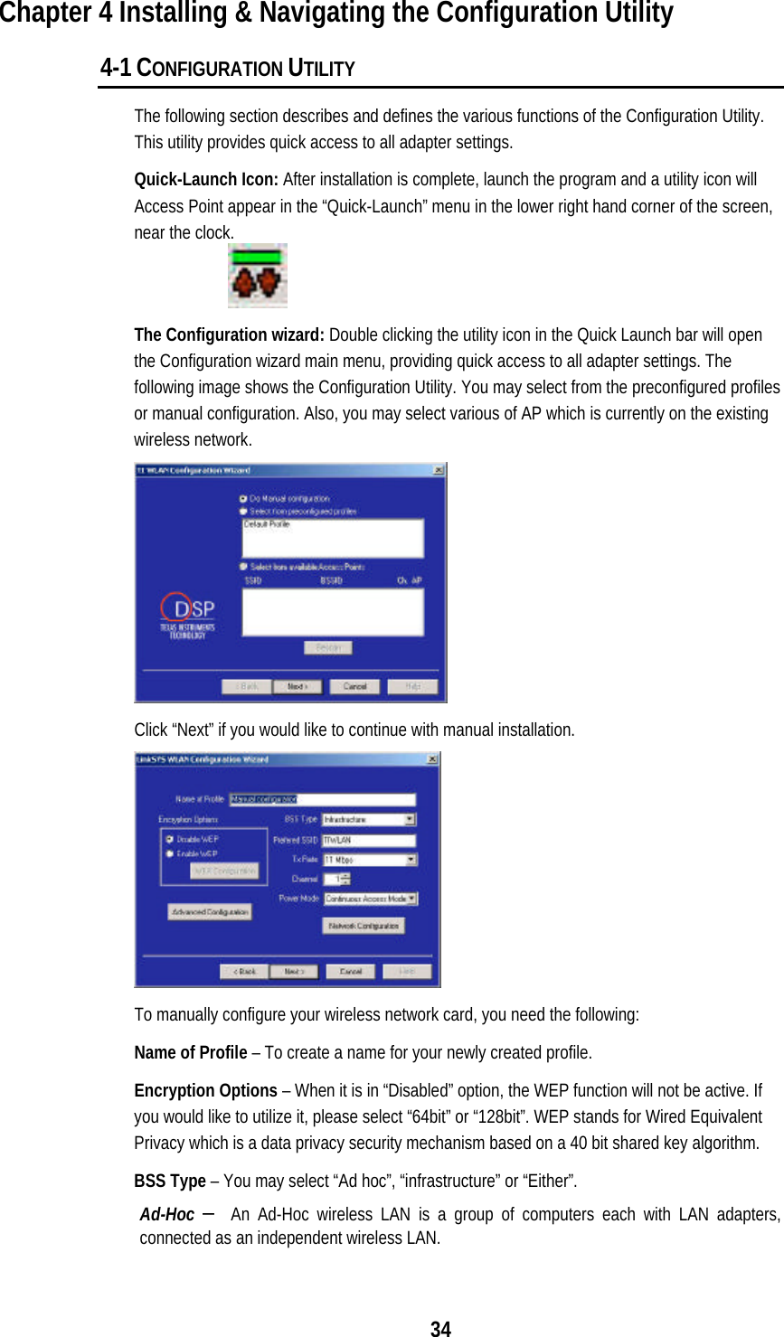
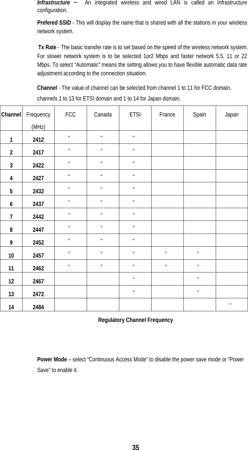
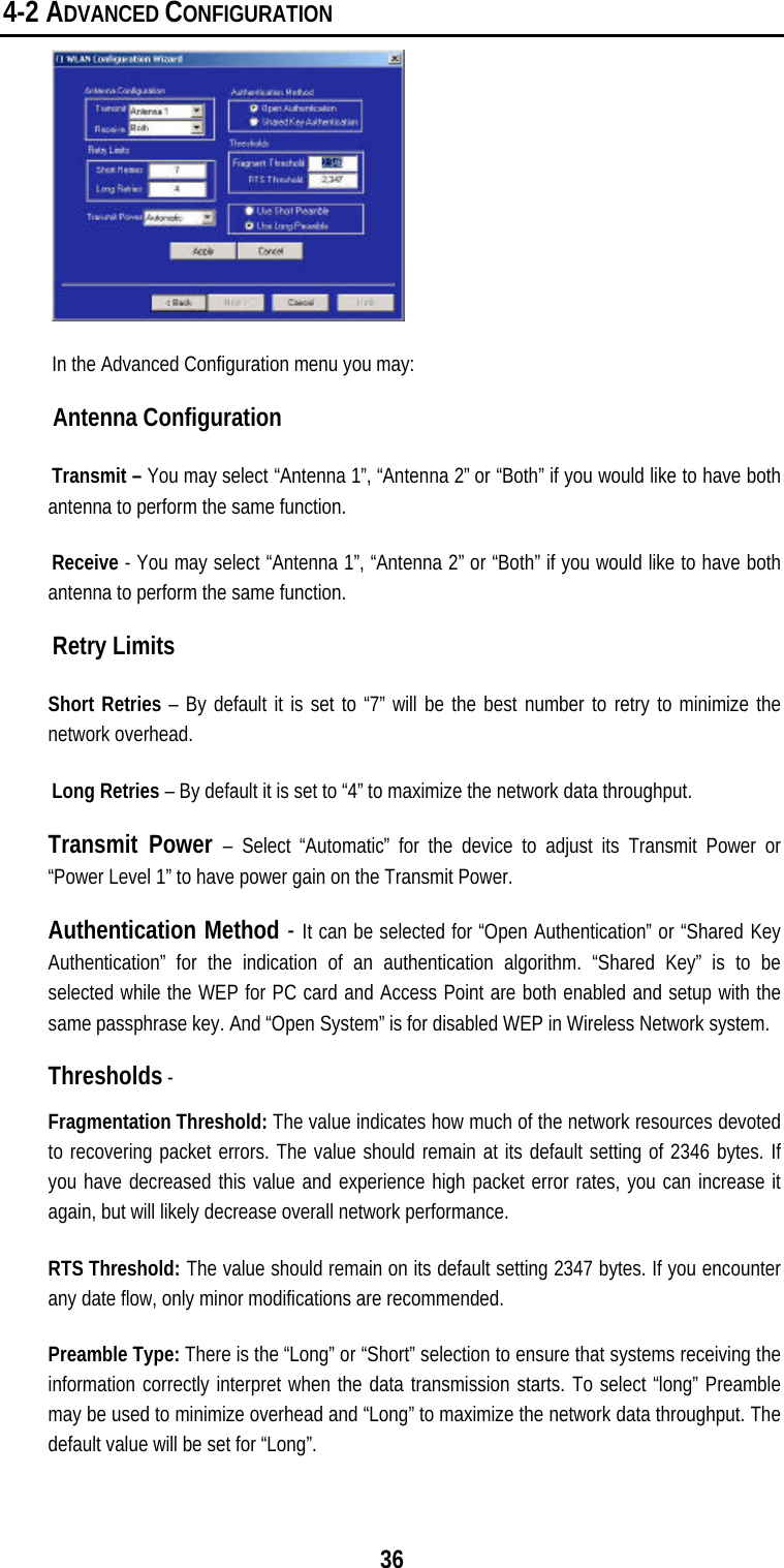
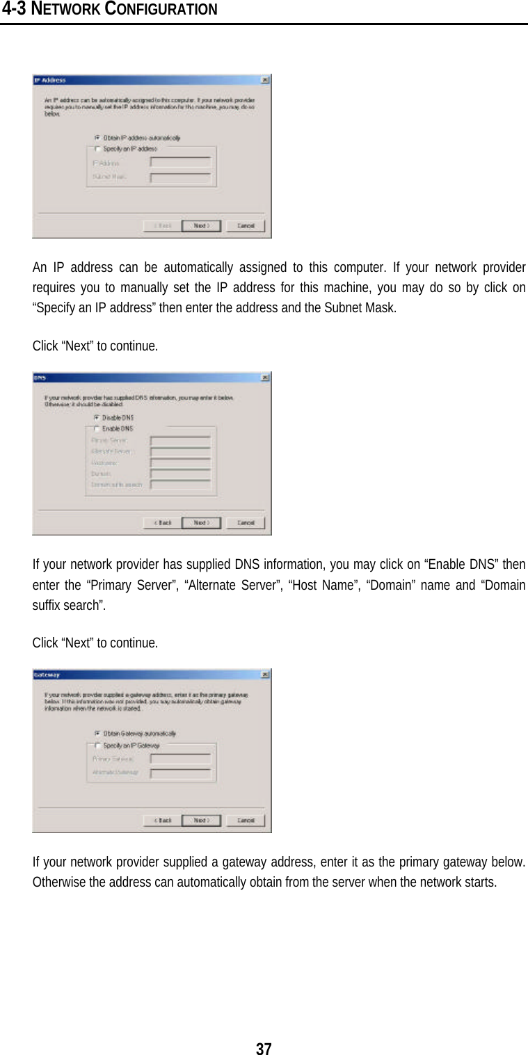
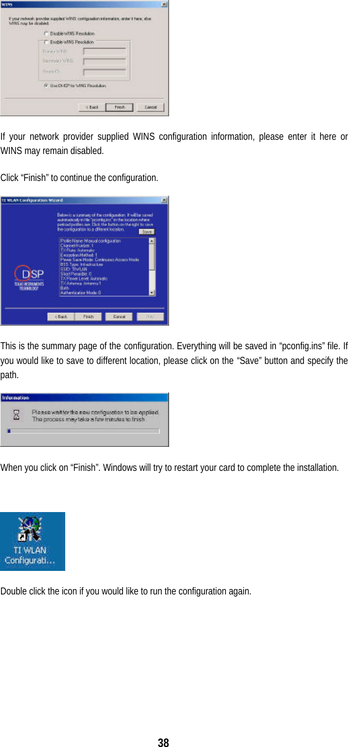
Global Sun Technology GL242204-0T Wireless 22Mbps RF Module User Manual GL242204 0T MANUAL
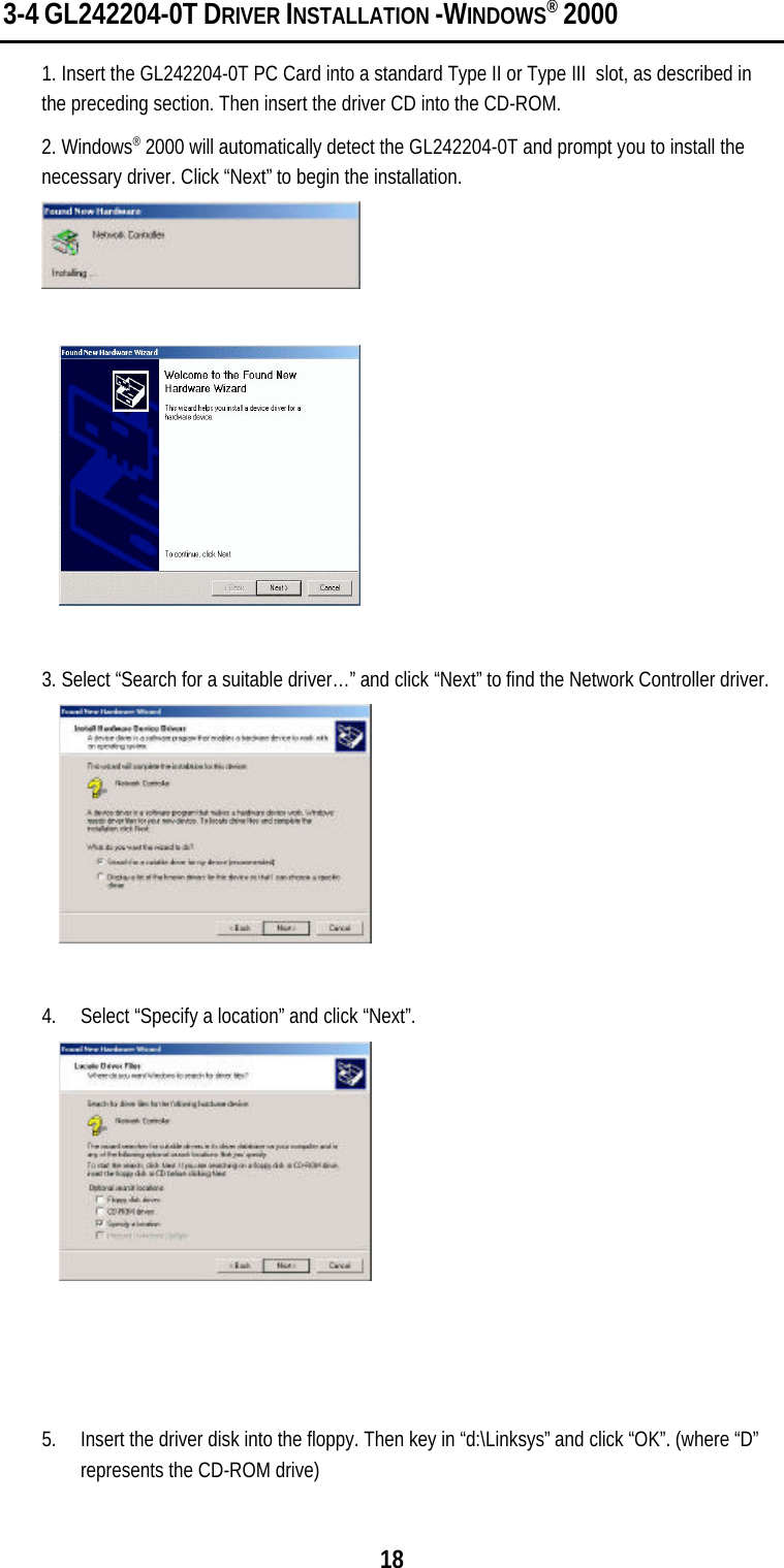
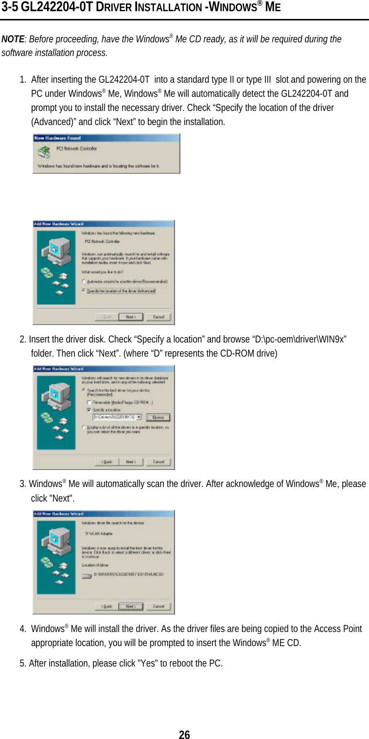
Global Sun Technology Inc Wireless 22Mbps RF Module GL242204 0T MANUAL
UserManual.wiki
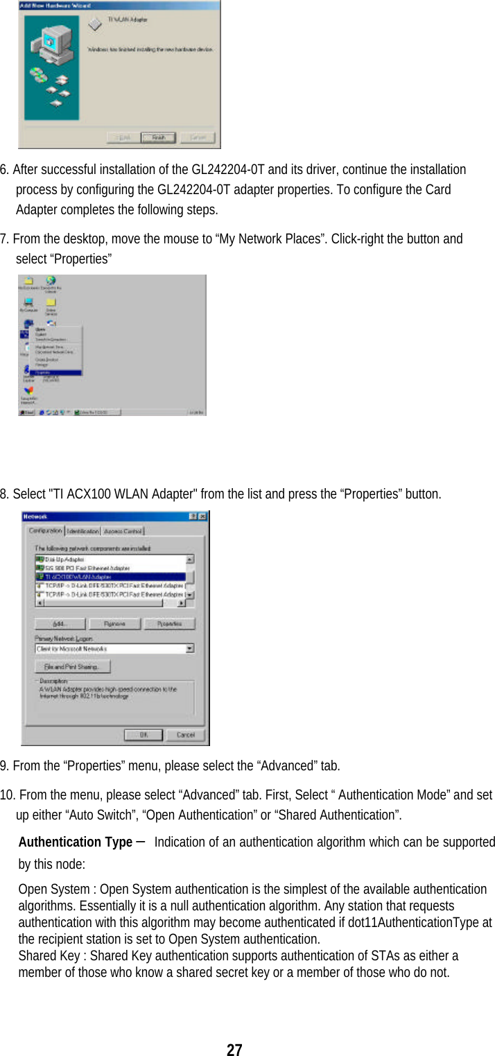
>
Global Sun Technology
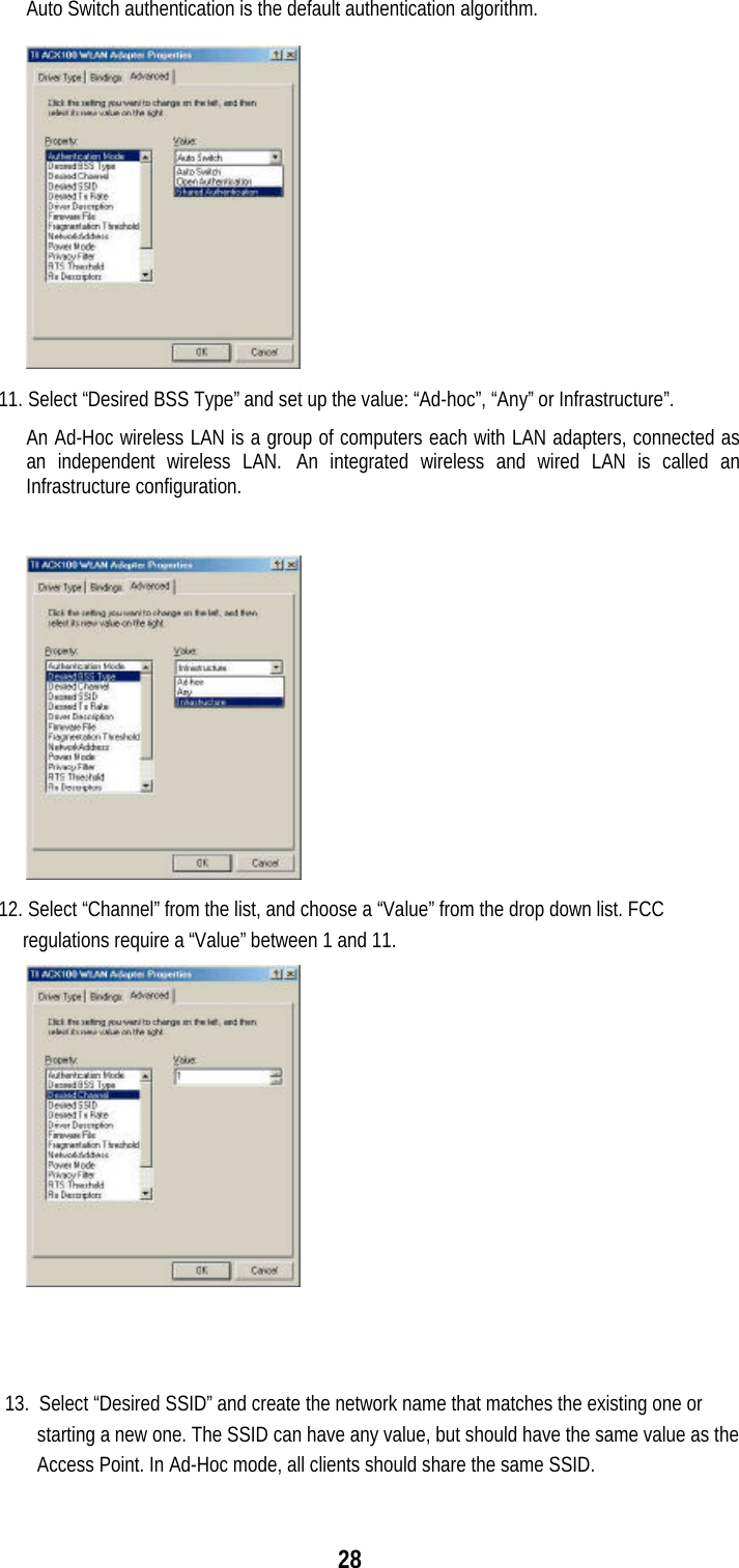
>
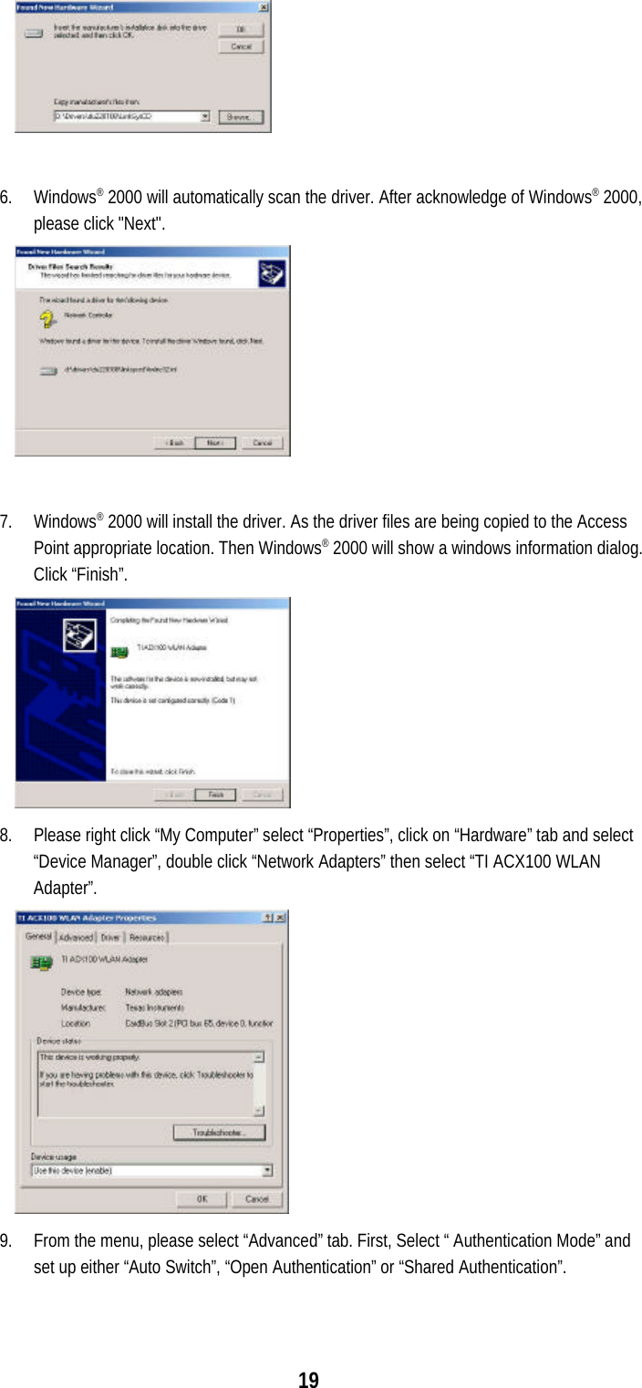
GL242204 0T User Manual
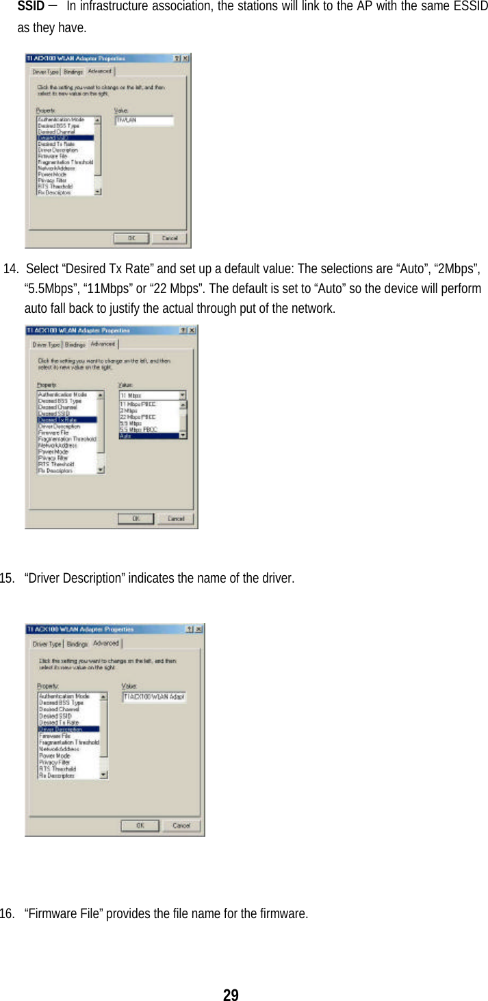
Manual
Navigation menu
Upload a User Manual
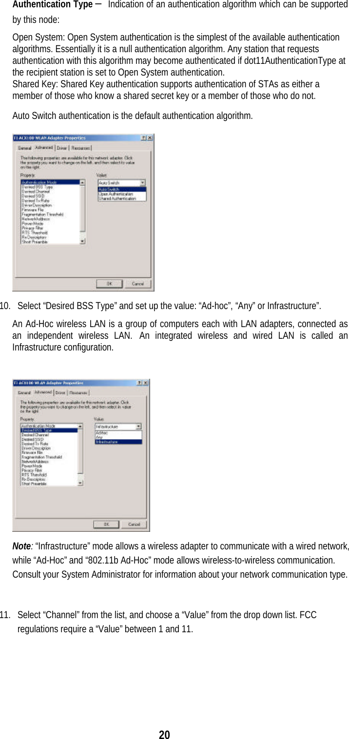
Namespaces
Wiki Guide
HTML
PDF
Info
Views
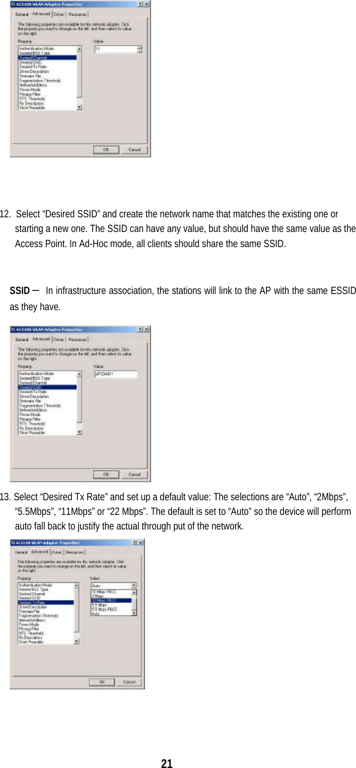
User Manual
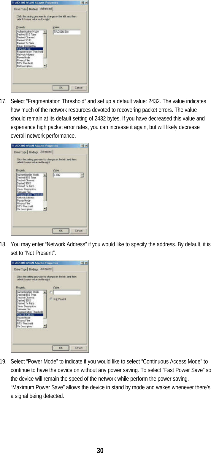
Discussion / Help
Navigation