Global Sun Technology GL242204-0T Wireless 22Mbps RF Module User Manual GL242204 0T MANUAL
Global Sun Technology Inc Wireless 22Mbps RF Module GL242204 0T MANUAL
Manual
G
GL
L2
24
42
22
20
04
4-
-0
0T
T
USER MANUAL
Version 1.0, Jan. 11, 2002
2
Federal Communications Commission Statement
This device complies with FCC Rules Part 15. Operation is subject to the following two conditions:
This device may not cause harmful interference.
This device must accept any interference received, including interference that may cause undesired
operation.
This equipment has been tested and found to comply with the limits for a Class B digital device,
pursuant to Part 15 of the FCC Rules. These limits are designed to provide reasonable protection
against harmful interference in a residential installation. This equipment generates uses and can
radiate radio frequency energy. If this equipment is not installed and used in accordance with the
manufacturer's instructions, it may cause harmful interference to radio communications. However,
there is no guarantee that interference will not occur in a particular installation. If this equipment
does cause harmful interference to radio or television reception, which can be determined by during
the equipment off and on, the user is encouraged to try to correct the interference by one or more of
the following measures:
Reorient or relocate the receiving antenna.
Increase the separation between the equipment and receiver.
Connect the equipment to an outlet on a circuit different from that to which the receiver is
connected.
Consult the dealer or an experienced radio/TV technician for help.
The use of shielded cables for connection of the monitor to the graphics card is required to assure
compliance with FCC regulations. Changes or modifications to this unit not expressly approved by
the party responsible for compliance could void the user's authority to operate this equipment.
This equipment complies with FCC radiation exposure limits set forth for an uncontrolled
environment. This equipment should be installed and operated with minimum distance 20cm
between the radiator and your body.
This transmitter must not be co-located or operating in conjunction with any other antenna or
transmitter.
FCC RF Radiation Exposure Statement:
This equipment complies with FCC RF radiation exposure limits set forth for an uncontrolled
environment. This equipment should be installed and operated with a minimum distance of 20
centimetres between the radiator and your body. This transmitter must not be co-located or
operating in conjunction with any other antenna or transmitter.
Manufacturer's Disclaimer Statement
The information in this document is subject to change without notice and does not represent a
commitment on the part of the vendor. No warranty or representation, either expressed or implied,
is made with respect to the quality, accuracy or fitness for any particular purpose of this document.
The manufacturer reserves the right to make changes to the content of this document and/or the
products associated with it at any time without obligation to notify any person or organization of
such changes. In no event will the manufacturer be liable for direct, indirect, special, incidental or
consequential damages arising out of the use or inability to use this product or documentation, even
if advised of the possibility of such damages. This document contains materials protected by
copyright. All rights are reserved. No part of this manual may be reproduced or transmitted in any
form, by any means or for any purpose without expressed written consent of its authors. Product
names appearing in this document are mentioned for identification purchases only. All trademarks,
product names or brand names appearing in this document are registered property of their
respective owners.
Printed in Taiwan
3
Contents
Chapter 1 About the GL242204-0T ............................................................................4
1-1 Features...............................................................................................................................................4
1-2 Applications..........................................................................................................................................4
1-3 Product Kit............................................................................................................................................5
Chapter 2 Network Configuration and Planning.......................................................6
2-1 Network Topology ................................................................................................................................6
2-2 Roaming...............................................................................................................................................8
Chapter 3 Adapter Installation and Configuration ...................................................9
3-1 System Requirements..........................................................................................................................9
3-2 Inserting the GL242204-0T PC CARD.................................................................................................9
3-3 GL242204-0T Driver Installation -Windows® 95/98............................................................................10
3-4 GL242204-0T Driver Installation -Windows® 2000.............................................................................18
3-5 GL242204-0T Driver Installation -Windows® Me................................................................................26
Chapter 4 Installing & Navigating the Configuration Utility ..................................34
4-1 Configuration Utility............................................................................................................................34
4-2 Advanced Configuration.....................................................................................................................36
4-3 Network Configuration........................................................................................................................37
Access Point appendix A Troubleshooting............................................................39
Access Point appendix B Glossary.........................................................................41

4
Chapter 1 About GL242204-0T
The GL242204-0T IEEE 802.11b is compatible with any standard, notebook computer Card Bus
slot. As a Plug-and-Play device, Windows 95/98/2000/ME/XP will automatically recognize the
GL242204-0T and initiate the installation process. Upon successful installation, the GL242204-0T
will communicate seamlessly with other GL242204-0T wireless home and office networking
products.
1-1 FEATURES
1. Supports up to 22 Mbps data rate: T-1 line alternative/replacement that dramatically cuts
costs.
2. Working range up to 800 ft. in an open environment enhances mobility.
3. Supports point-to-point and point-to-multipoint access provides increased flexibility.
4. Seamless connectivity to wired Ethernet and PC network LAN’s offers quick, trouble-free
integration with existing networks.
5. Robust Direct Sequence Spread Spectrum (DSSS) technology provides secure,
interference-resistant wireless connection.
6. Wireless connections eliminate the hassle and cost of cabling.
7. Supports a wide range of LAN (Local Area Network) Network Operating Systems (NOS)
including Windows ® 95/98/2000/ME/XP.
8. Easy Plug and Play installation
9. Dual SCX connector for external antennas
10. Greater flexibility to locate or move networked PC’s
1-2 APPLICATIONS
GL242204-0T products offer a fast, reliable, cost-effective solution for wireless client access to the
network the following Applications and environments:
§ Remote access to corporate network information
§ E-mail, file transfer and terminal emulation
§ Difficult-to-wire environments
§ Historic or listed buildings
§ Buildings with asbestos insulation
§ Open areas where wiring is difficult to employ
§ Frequently changing environments
§ Retailers, manufacturers or other organizations that frequently rearrange the workplace or
relocate
§ Temporary LANs for special projects or peak time usage

5
§ Trade shows, exhibitions and construction sites that employ temporary networks.
Retailers, airline and shipping companies that need additional workstations for a peak
period and Auditors that require workgroups at customer sites.
§ Access to database for mobile workers
§ Medical, Technical and Retail specialists that require roaming access to a database or
other network resources.
§ SOHO (Small Office and Home Office) users
§ Perfect for users that need a small, easy-to-install network that deploys rapidly.
§ Inter-building connection
§ Wireless building-to-building networks are quickly and easily installed, require no monthly
lease fees, and provide the flexibility to reconfigure easily.
1-3 PRODUCT KIT
The GL242204-0T product kit includes the following items. Ensure that the items in the following list
have been included. If any of the listed items are missing, please contact your local dealer.
§ 1 X GL242204-0T Card Bus Adapter
§ 1 X Driver & Utility CD pack
§ 1 X User Manual
6
Chapter 2 Network Configuration and Planning
The GL242204-0T supports legacy Ethernet LAN network configuration options as defined by the
IEEE 802 standards committee.
The GL242204-0T can be configured as:
§ Ad-Hoc for departmental or SOHO LANs
§ Infrastructure for enterprise LANs
§ LAN-Interconnection for point-to-point link as a campus backbone
2-1 NETWORK TOPOLOGY
Desktop PC
with
PCMCIA Wireless LAN Card
Desktop PC
with
PCMCIA Wireless LAN Card
Notebook
with
PCMCIA Wireless LAN Card
Notebook
with
PCMCIA Wireless LAN Card
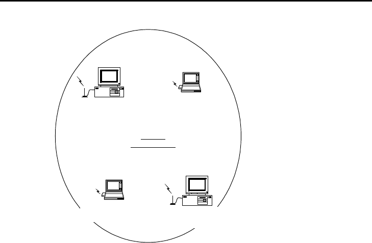
Ad Hoc
Wireless LAN
Fig. 1 - Ad-Hoc Wireless LAN
An Ad-Hoc wireless LAN is a group of computers, each equipped with one GL242204-0T,
connected as an independent wireless LAN. Computers in a specific Ad-Hoc wireless LAN must be
configured to share the same radio channel.
Ad-Hoc wireless LAN configurations are Access Point appropriate for branch level departments or
SOHO operations
7
Ethernet
Desktop PC with ethernet Desktop PC with ethernet Sever
Access
Point Access Point
Notebook
with
PCMCIA Wireless LAN Card
Notebook
with
PCMCIA Wireless LAN Card
Notebook
with
PCMCIA Wireless LAN Card
Desktop PC
with
PCMCIA Wireless LAN Card
Desktop PC
with
PCMCIA Wireless LAN Card
Desktop PC
with
PCMCIA Wireless LAN Card
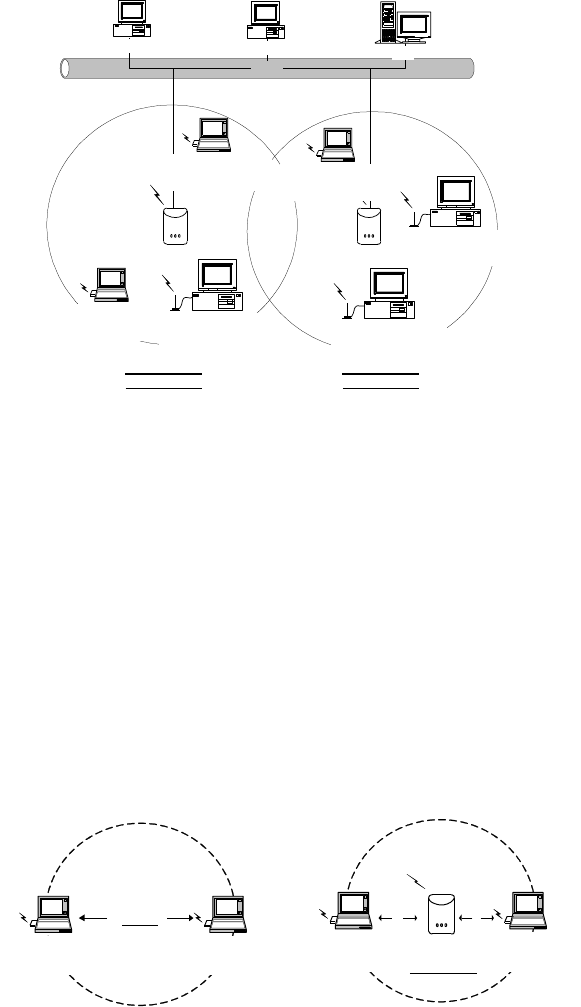
Infrastructure
Wireless LAN Infrastructure
Wireless LAN
Fig. 2 - Infrastructure Wireless LAN Configuration
The GL242204-0T provides access to a wired LAN for wireless workstations. An integrated wireless
and wired LAN is called an Infrastructure configuration. A group of GL242204-0T PC users and an
Access Point compose a Basic Service Set (BSS). Each GL242204-0T PC in a BSS can talk to any
computer in the wired LAN infrastructure via the Access Point.
An Infrastructure configuration extends the accessibility of a GL242204-0T equipped PC to a wired
LAN, and doubles the effective wireless transmission range for 2 GL242204-0T PCs. Since the
Access Point is able to forward data within its BSS, the effective transmission range in an
infrastructure LAN is doubled.
Notebook
with
PCMCIA Wireless LAN Card
Notebook
with
PCMCIA Wireless LAN Card
Ad Hoc
Notebook
with
PCMCIA Wireless LAN Card
Notebook
with
PCMCIA Wireless LAN Card
Infrastructure
Access Point
Fig. 3 - The effective Transmission Range
The use of a unique ID in a BSS is essential. All GL242204-0T equipped PCs configured without
roaming options in an independent BSS must be configured with a BSS ID corresponding to the
ACCESS POINT used in the BSS. Check your ACCESS POINT for its BSS ID or use the Access
Point Browser Utility program to determine the BSS ID.
The Infrastructure Wireless LAN configuration is Access Point appropriate for enterprise-scale
wireless access to a central database, or as a wireless Access Point application for mobile users.
A point-to-point LAN configuration is possible when two access points are linked with an optional
directional antenna (the directional antenna is an optional accessory, please contact your dealer for
8
information). The optional directional antenna makes LAN-Interconnection to a wireless backbone
between buildings possible.
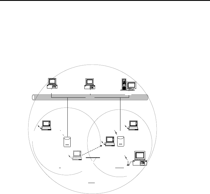
2-2 ROAMING
Infrastructure mode also supports roaming capabilities for mobile users. More than one BSS can be
configured as an Extended Service Set (ESS). The continuous network allows users to roam freely
within an ESS. All GL242204-0T PCs and Access Points within one ESS must be configured with
the same ESS ID and use the same radio channel.
Ethernet
Desktop PC with ethernet Desktop PC with ethernet Sever
Access Point Access
Point
Notebook
with
PCMCIA Wireless LAN Card
Notebook
with
PCMCIA Wireless LAN Card
Notebook
with
PCMCIA Wireless LAN Card
Desktop PC
with
PCMCIA Wireless LAN Card
BSS1 BSS2
ESS
Notebook
with
PCMCIA Wireless LAN Card
Roaming
Fig. 4 - Roaming in an Extended Service Set (ESS)
Before enabling an ESS with roaming capability, choosing a feasible radio channel and optimum
Access Point position is recommended. Proper Access Point positioning combined with a clear
radio signal will greatly enhance performance.
9
Chapter 3 Adapter Installation and Configuration
3-1 SYSTEM REQUIREMENTS
In order to install and use the GL242204-0T your PC system must meet the following requirements:
§ A Card Bus slot
§ PCMCIA revision 2.10 compliant card and socket services
§ Windows® 95, 98, ME.2000, XP.
§ 500 Kbytes free disk space for utility and driver installation
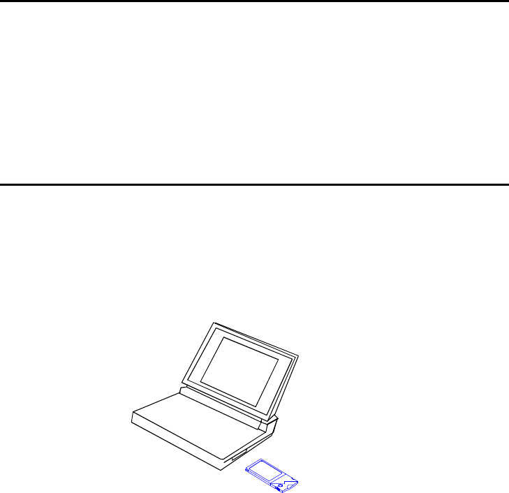
3-2 INSERTING THE GL242204-0T PC CARD
To insert the GL242204-0T Network Adapter into a notebook computer, do the following:
1. Locate an available Card Bus slot.
2. With the 68-pin connector facing the Card Bus slot and the GL242204-0T card label
facing up slide completely into the Card Bus slot.
Fig. 5 Insert the GL242204-0T into Notebook
After properly inserting the Network Adapter into your notebook, continue with the GL242204-0T
driver and Configuration Utility installation.
NOTE: The Card Bus slot allows “hot swap” . You may insert or remove the GL242204-0T from
the slot anytime, even when the power of your computer is on.
NOTE: Windows® requires that the Network card and socket services must be compliant with the
PCMCIA revision 2.10 specification. Please check the documentation of the PCMCIA driver
before installing the GL242204-0T.
NOTE: To comply with FCC RF exposure requirements, this device should be operated in
lap-top computer configurations with a separation distance of 20 cm or more between the
antenna and persons. The antenna should not be operated next to a person.
10
3-3 GL242204-0T DRIVER INSTALLATION -WINDOWS® 95/98
Note: Before proceeding, have the Windows® 98 CD ready, as it will be required during the software
installation process.
1. Insert the GL242204-0T into a standard Type II or Type III slot, as described in the
preceding section.
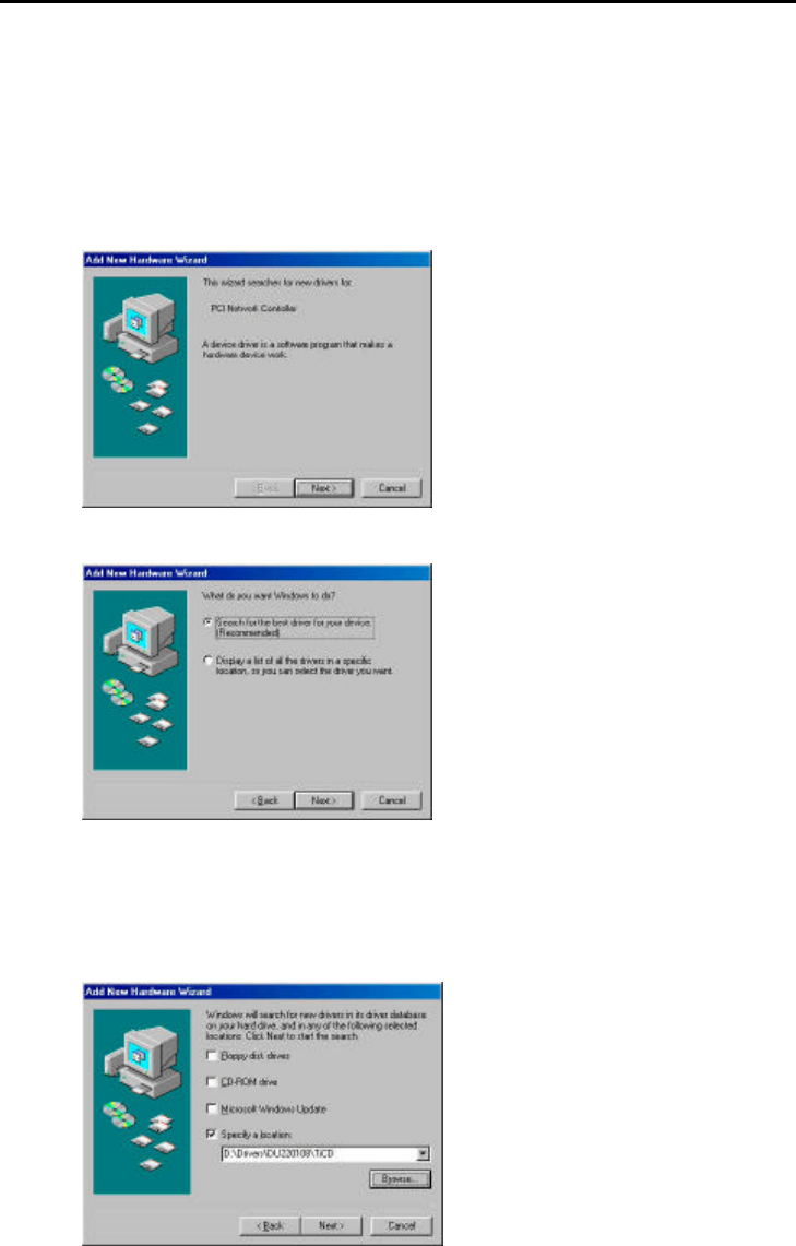
2. Windows® 98 will automatically detect the GL242204-0T and prompt you to install the
necessary driver. Click “Next” to begin the installation.
3. Check “Search for the best driver… “and click “Next”.
4. Check “CD-ROM Driver” and click “Browse”. Double-click the “D:\Drivers\DU220108\TiCD”
folder icon from the list. Windows® will automatically enter the path click “Next”. (where "D"
represents a CD-ROM)
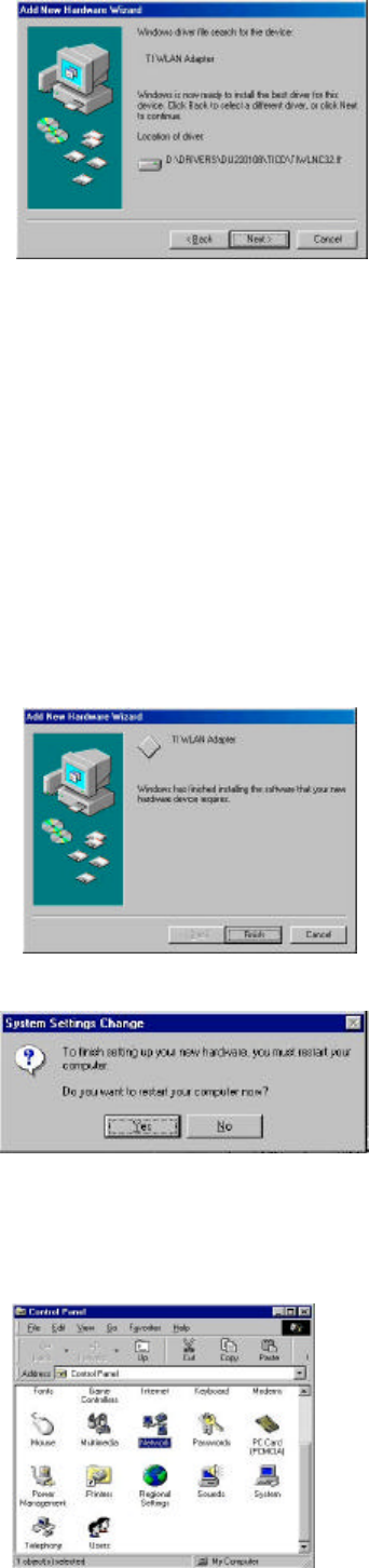
5. Windows® will then acknowledge that it has found the Access Point appropriate driver, click
“Next”
11
Windows® will now install the driver
As the driver files are being copied to the Access Point appropriate location, you will be
prompted to insert the Windows® 98 CD.
6. Insert the Windows® 98 CD. Select “D:\win98” from the drop down list (where “D” represents
the CD-ROM drive), click “OK”.
NOTE: You must insert the Windows 98®CD as the driver installation requires special files that
will not be available even if you have stored a copy of Windows® 98 on your hard drive.
7. After Windows® has finished installing the Access Point appropriate files click “Finish”
8. You will be prompted to restart your computer and click "Yes" to complete the installation.
9. After successful installation of the GL242204-0T and its driver, continue the installation
process by configuring the GL242204-0T PC Card properties. From the Control Panel, double-
click the “Network” icon.
12
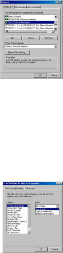
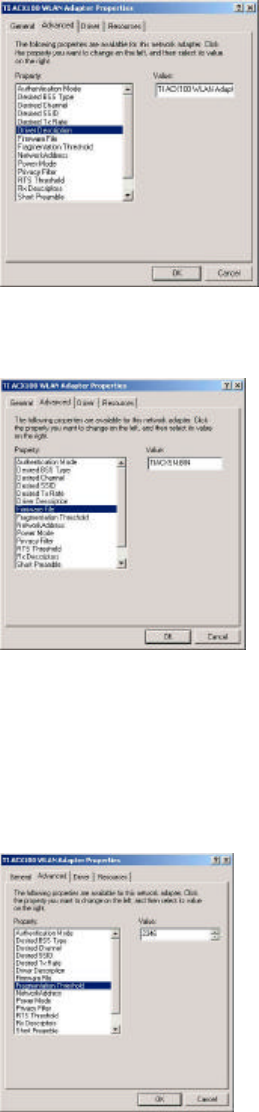
10. Select "TI ACX100 WLAN Adapter" from the list and press the “Properties” button.
11. From the “Properties” menu, please select the “Advanced” tab.
12. From the menu, please select “Advanced” tab. First, Select “ Authentication Mode” and set
up either “Auto Switch”, “Open Authentication” or “Shared Authentication”.
Authentication Type ─ Indication of an authentication algorithm which can be supported
by this node:
Open System : Open System authentication is the simplest of the available authentication
algorithms. Essentially it is a null authentication algorithm. Any station that requests
authentication with this algorithm may become authenticated if dot11AuthenticationType at
the recipient station is set to Open System authentication.
Shared Key : Shared Key authentication supports authentication of STAs as either a
member of those who know a shared secret key or a member of those who do not.
Auto Switch authentication is the default authentication algorithm.
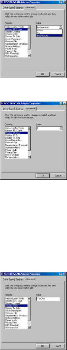
5. Select “Desired BSS Type” and set up the value: “Ad-hoc”, “Any” or Infrastructure”.
An Ad-Hoc wireless LAN is a group of computers each with LAN adapters, connected as
an independent wireless LAN. An integrated wireless and wired LAN is called an
Infrastructure configuration.
13
6. Select “Channel” from the list, and choose a “Value” from the drop down list. FCC
regulations require a “Value” between 1 and 11.
7. Select “Desired SSID” and create the network name that matches the existing one or
starting a new one. The SSID can have any value, but should have the same value as the
Access Point. In Ad-Hoc mode, all clients should share the same SSID.
SSID ─ In infrastructure association, the stations will link to the AP with the same ESSID
as they have.
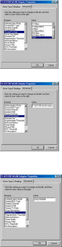
8. Select “Desired Tx Rate” and set up a default value: The selections are “Auto”, “2Mbps”,
“5.5Mbps”, “11Mbps” or “22 Mbps”. The default is set to “Auto” so the device will perform
auto fall back to justify the actual through put of the network.
14
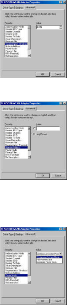
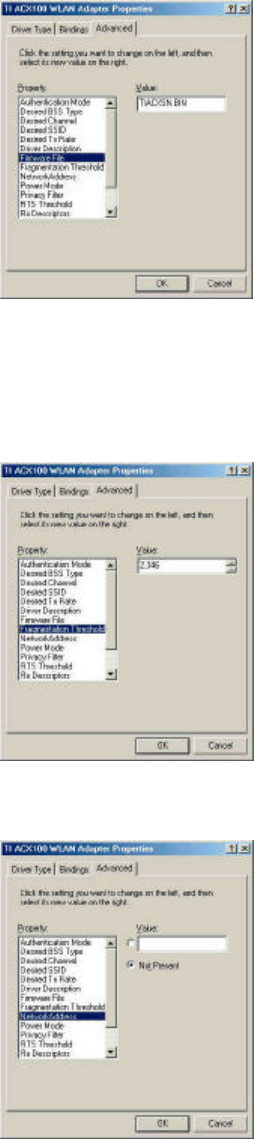
21. “Driver Description” indicates the name of the driver.
21. “Firmware File” provides the file name for the firmware.
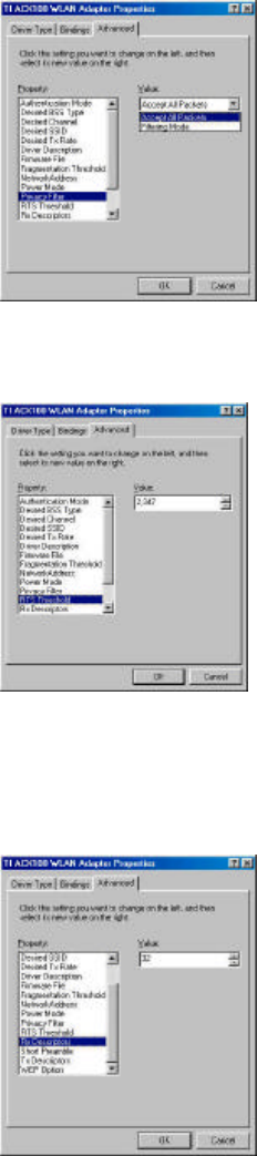
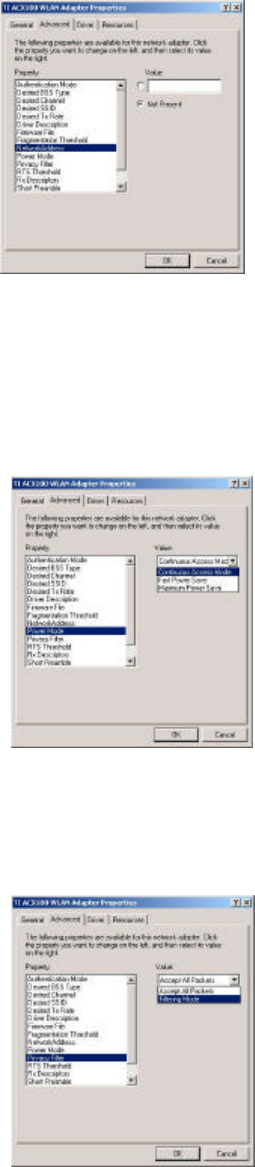
21. Select “Fragmentation Threshold” and set up a default value: 2432. The value indicates
how much of the network resources devoted to recovering packet errors. The value
should remain at its default setting of 2432 bytes. If you have decreased this value and
experience high packet error rates, you can increase it again, but will likely decrease
overall network performance.
15
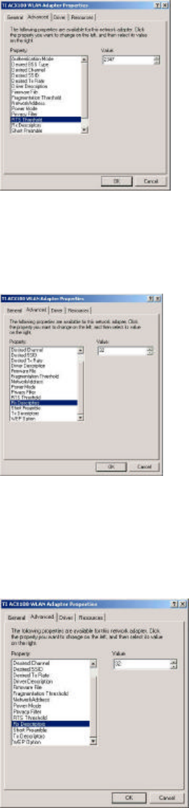
21. You may enter “Network Address” if you would like to specify the address. By default, it is
set to “Not Present”.
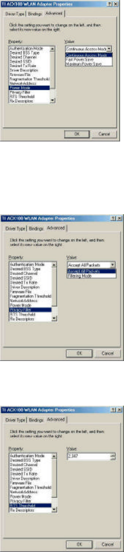
21. Select “Power Mode” to indicate if you would like to select “Continuous Access Mode” to
continue to have the device on without any power saving. To select “Fast Power Save” so
the device will remain the speed of the network while perform the power saving.
“Maximum Power Save” allows the device in stand by mode and wakes whenever there’s
a signal being detected.
21. Click on “Privacy Filter” to select if you would like to “Accept All Packets” which means
the device will accept any data that is coming from the network. In “Filtering Mode” means
the device will filter out any unnecessary packets from the network.
16
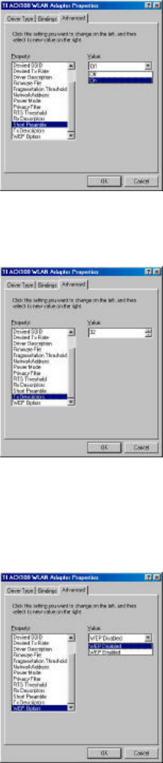
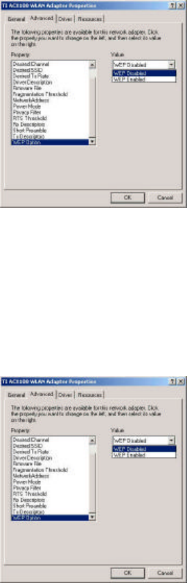
15. RTS Threshold: The value should remain on its default setting 2432 bytes. If you
encounter any date flow, only minor modifications are recommended.
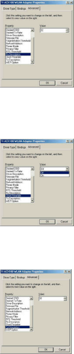
16. “Rx Descriptors” means the receiving butter for your networks throughput. The greater
value will cause data loss where the less value will decrease the networks performance.
The default is set to 32.
17. “Short Preamble” means there is the “Off” or “On” selection to ensure that systems
receiving the information correctly interpret when the data transmission starts. To select
“On” Preamble may be used to minimize overhead and “Off” to maximize the network
data throughput. The default value will be set for “Off”.
17
18. “Tx Descriptors” means the transmitting butter for the network’s throughput. The greater
value will cause data loss where the less value will decrease the networks performance.
The default is set to 32.
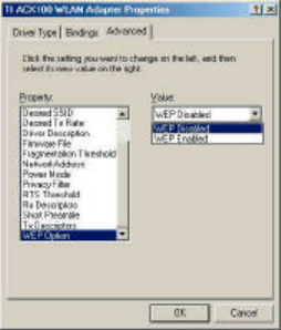
19. “WEP Option” means this will display the status of encryption protocol. It can be “Off”, if
the WEP encryption protocol is not enabled. When it is necessary to use, it will be set to
“On”. Wired Equivalent Privacy (WEP) is an encryption scheme used to protect wireless
data communication. To enable the icon will prevent other stations without the same WEP
key from linking with the AP.
18
3-4 GL242204-0T DRIVER INSTALLATION -WINDOWS® 2000
1. Insert the GL242204-0T PC Card into a standard Type II or Type III slot, as described in
the preceding section. Then insert the driver CD into the CD-ROM.
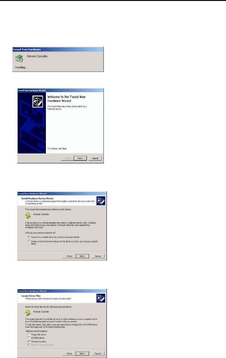
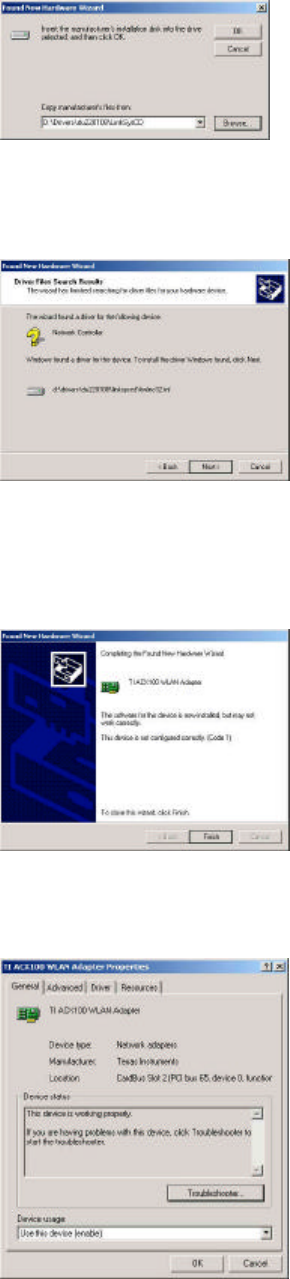
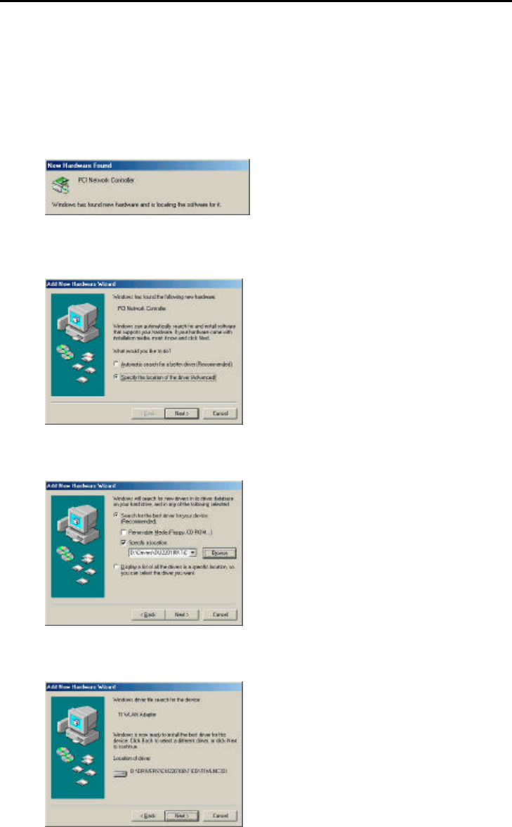
2. Windows® 2000 will automatically detect the GL242204-0T and prompt you to install the
necessary driver. Click “Next” to begin the installation.
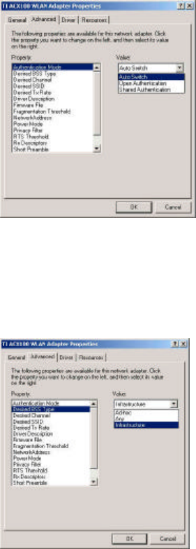
3. Select “Search for a suitable driver…” and click “Next” to find the Network Controller driver.
4. Select “Specify a location” and click “Next”.
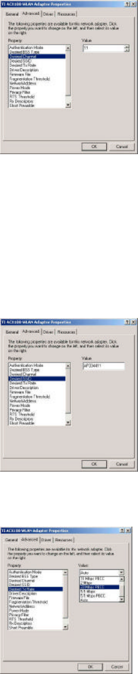
5. Insert the driver disk into the floppy. Then key in “d:\Linksys” and click “OK”. (where “D”
represents the CD-ROM drive)
19
6. Windows® 2000 will automatically scan the driver. After acknowledge of Windows® 2000,
please click "Next".
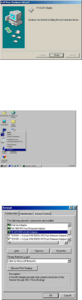
7. Windows® 2000 will install the driver. As the driver files are being copied to the Access
Point appropriate location. Then Windows® 2000 will show a windows information dialog.
Click “Finish”.
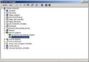
8. Please right click “My Computer” select “Properties”, click on “Hardware” tab and select
“Device Manager”, double click “Network Adapters” then select “TI ACX100 WLAN
Adapter”.
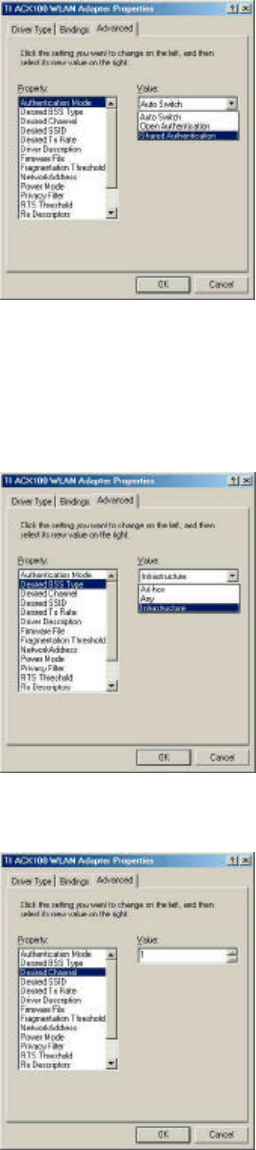
9. From the menu, please select “Advanced” tab. First, Select “ Authentication Mode” and
set up either “Auto Switch”, “Open Authentication” or “Shared Authentication”.
20
Authentication Type ─ Indication of an authentication algorithm which can be supported
by this node:
Open System: Open System authentication is the simplest of the available authentication
algorithms. Essentially it is a null authentication algorithm. Any station that requests
authentication with this algorithm may become authenticated if dot11AuthenticationType at
the recipient station is set to Open System authentication.
Shared Key: Shared Key authentication supports authentication of STAs as either a
member of those who know a shared secret key or a member of those who do not.
Auto Switch authentication is the default authentication algorithm.
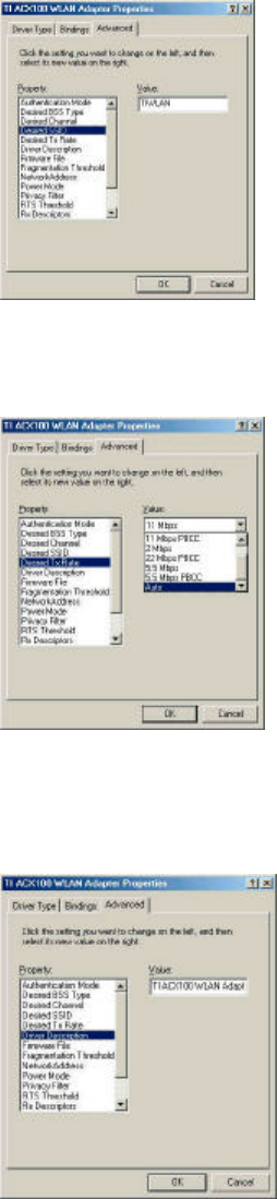
10. Select “Desired BSS Type” and set up the value: “Ad-hoc”, “Any” or Infrastructure”.
An Ad-Hoc wireless LAN is a group of computers each with LAN adapters, connected as
an independent wireless LAN. An integrated wireless and wired LAN is called an
Infrastructure configuration.
Note: “Infrastructure” mode allows a wireless adapter to communicate with a wired network,
while “Ad-Hoc” and “802.11b Ad-Hoc” mode allows wireless-to-wireless communication.
Consult your System Administrator for information about your network communication type.
11. Select “Channel” from the list, and choose a “Value” from the drop down list. FCC
regulations require a “Value” between 1 and 11.
21
12. Select “Desired SSID” and create the network name that matches the existing one or
starting a new one. The SSID can have any value, but should have the same value as the
Access Point. In Ad-Hoc mode, all clients should share the same SSID.
SSID ─ In infrastructure association, the stations will link to the AP with the same ESSID
as they have.
13. Select “Desired Tx Rate” and set up a default value: The selections are “Auto”, “2Mbps”,
“5.5Mbps”, “11Mbps” or “22 Mbps”. The default is set to “Auto” so the device will perform
auto fall back to justify the actual through put of the network.
22
14. Driver Description” indicates the name of the driver.
21. “Firmware File” provides the file name for the firmware.
21. Select “Fragmentation Threshold” and set up a default value: 2432. The value indicates
how much of the network resources devoted to recovering packet errors. The value
should remain at its default setting of 2432 bytes. If you have decreased this value and
experience high packet error rates, you can increase it again, but will likely decrease
overall network performance.
21. You may enter “Network Address” if you would like to specify the address. By default, it is
set to “Not Present”.
23
21. Select “Power Mode” to indicate if you would like to select “Continuous Access Mode” to
continue to have the device on without any power saving. To select “Fast Power Save” so
the device will remain the speed of the network while perform the power saving.
“Maximum Power Save” allows the device in stand by mode and wakes whenever there’s
a signal being detected.
21. Click on “Privacy Filter” to select if you would like to “Accept All Packets” which means
the device will accept any data that is coming from the network. In “Filtering Mode” means
the device will filter out any unnecessary packets from the network.
20. RTS Threshold: The value should remain on its default setting 2432 bytes. If you
encounter any date flow, only minor modifications are recommended.
24
21. “Rx Descriptors” means the receiving butter for your networks throughput. The greater
value will cause data loss where the less value will decrease the networks performance.
The default is set to 32.
22. “Short Preamble” means there is the “Off” or “On” selection to ensure that systems
receiving the information correctly interpret when the data transmission starts. To select
“On” Preamble may be used to minimize overhead and “Off” to maximize the network
data throughput. The default value will be set for “Off”.
23. “Tx Descriptors” means the transmitting butter for the network’s throughput. The greater
value will cause data loss where the less value will decrease the networks performance.
The default is set to 32.
25
24. “WEP Option” means this will display the status of encryption protocol. It can be “Off”, if
the WEP encryption protocol is not enabled. When it is necessary to use, it will be set to
“On”. Wired Equivalent Privacy (WEP) is an encryption scheme used to protect wireless
data communication. To enable the icon will prevent other stations without the same WEP
key from linking with the AP.
26
3-5 GL242204-0T DRIVER INSTALLATION -WINDOWS® ME
NOTE: Before proceeding, have the Windows® Me CD ready, as it will be required during the
software installation process.
1. After inserting the GL242204-0T into a standard type II or type III slot and powering on the
PC under Windows® Me, Windows® Me will automatically detect the GL242204-0T and
prompt you to install the necessary driver. Check “Specify the location of the driver
(Advanced)” and click “Next” to begin the installation.
2. Insert the driver disk. Check “Specify a location” and browse “D:\pc-oem\driver\WIN9x”
folder. Then click “Next”. (where “D” represents the CD-ROM drive)
3. Windows® Me will automatically scan the driver. After acknowledge of Windows® Me, please
click "Next".
4. Windows® Me will install the driver. As the driver files are being copied to the Access Point
appropriate location, you will be prompted to insert the Windows® ME CD.
5. After installation, please click "Yes" to reboot the PC.
27
6. After successful installation of the GL242204-0T and its driver, continue the installation
process by configuring the GL242204-0T adapter properties. To configure the Card
Adapter completes the following steps.
7. From the desktop, move the mouse to “My Network Places”. Click-right the button and
select “Properties”
8. Select "TI ACX100 WLAN Adapter" from the list and press the “Properties” button.
9. From the “Properties” menu, please select the “Advanced” tab.
10. From the menu, please select “Advanced” tab. First, Select “ Authentication Mode” and set
up either “Auto Switch”, “Open Authentication” or “Shared Authentication”.
Authentication Type ─ Indication of an authentication algorithm which can be supported
by this node:
Open System : Open System authentication is the simplest of the available authentication
algorithms. Essentially it is a null authentication algorithm. Any station that requests
authentication with this algorithm may become authenticated if dot11AuthenticationType at
the recipient station is set to Open System authentication.
Shared Key : Shared Key authentication supports authentication of STAs as either a
member of those who know a shared secret key or a member of those who do not.
28
Auto Switch authentication is the default authentication algorithm.
11. Select “Desired BSS Type” and set up the value: “Ad-hoc”, “Any” or Infrastructure”.
An Ad-Hoc wireless LAN is a group of computers each with LAN adapters, connected as
an independent wireless LAN. An integrated wireless and wired LAN is called an
Infrastructure configuration.
12. Select “Channel” from the list, and choose a “Value” from the drop down list. FCC
regulations require a “Value” between 1 and 11.
13. Select “Desired SSID” and create the network name that matches the existing one or
starting a new one. The SSID can have any value, but should have the same value as the
Access Point. In Ad-Hoc mode, all clients should share the same SSID.
29
SSID ─ In infrastructure association, the stations will link to the AP with the same ESSID
as they have.
14. Select “Desired Tx Rate” and set up a default value: The selections are “Auto”, “2Mbps”,
“5.5Mbps”, “11Mbps” or “22 Mbps”. The default is set to “Auto” so the device will perform
auto fall back to justify the actual through put of the network.
15. “Driver Description” indicates the name of the driver.
16. “Firmware File” provides the file name for the firmware.
30
17. Select “Fragmentation Threshold” and set up a default value: 2432. The value indicates
how much of the network resources devoted to recovering packet errors. The value
should remain at its default setting of 2432 bytes. If you have decreased this value and
experience high packet error rates, you can increase it again, but will likely decrease
overall network performance.
18. You may enter “Network Address” if you would like to specify the address. By default, it is
set to “Not Present”.
19. Select “Power Mode” to indicate if you would like to select “Continuous Access Mode” to
continue to have the device on without any power saving. To select “Fast Power Save” so
the device will remain the speed of the network while perform the power saving.
“Maximum Power Save” allows the device in stand by mode and wakes whenever there’s
a signal being detected.
31
20. Click on “Privacy Filter” to select if you would like to “Accept All Packets” which means
the device will accept any data that is coming from the network. In “Filtering Mode” means
the device will filter out any unnecessary packets from the network.
21. RTS Threshold: The value should remain on its default setting 2432 bytes. If you
encounter any date flow, only minor modifications are recommended.
22. “Rx Descriptors” means the receiving butter for your networks throughput. The greater
value will cause data loss where the less value will decrease the networks performance.
The default is set to 32.
32
23. “Short Preamble” means there is the “Off” or “On” selection to ensure that systems
receiving the information correctly interpret when the data transmission starts. To select
“On” Preamble may be used to minimize overhead and “Off” to maximize the network
data throughput. The default value will be set for “Off”.
24. “Tx Descriptors” means the transmitting butter for the network’s throughput. The greater
value will cause data loss where the less value will decrease the networks performance.
The default is set to 32.
25. “WEP Option” means this will display the status of encryption protocol. It can be “Off”, if
the WEP encryption protocol is not enabled. When it is necessary to use, it will be set to
“On”. Wired Equivalent Privacy (WEP) is an encryption scheme used to protect wireless
33
data communication. To enable the icon will prevent other stations without the same WEP
key from linking with the AP.
34
Chapter 4 Installing & Navigating the Configuration Utility
4-1 CONFIGURATION UTILITY
The following section describes and defines the various functions of the Configuration Utility.
This utility provides quick access to all adapter settings.
Quick-Launch Icon: After installation is complete, launch the program and a utility icon will
Access Point appear in the “Quick-Launch” menu in the lower right hand corner of the screen,
near the clock.
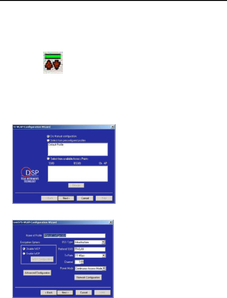
The Configuration wizard: Double clicking the utility icon in the Quick Launch bar will open
the Configuration wizard main menu, providing quick access to all adapter settings. The
following image shows the Configuration Utility. You may select from the preconfigured profiles
or manual configuration. Also, you may select various of AP which is currently on the existing
wireless network.
Click “Next” if you would like to continue with manual installation.
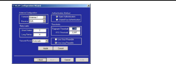
To manually configure your wireless network card, you need the following:
Name of Profile – To create a name for your newly created profile.
Encryption Options – When it is in “Disabled” option, the WEP function will not be active. If
you would like to utilize it, please select “64bit” or “128bit”. WEP stands for Wired Equivalent
Privacy which is a data privacy security mechanism based on a 40 bit shared key algorithm.
BSS Type – You may select “Ad hoc”, “infrastructure” or “Either”.
Ad-Hoc ─ An Ad-Hoc wireless LAN is a group of computers each with LAN adapters,
connected as an independent wireless LAN.

35
Infrastructure ─ An integrated wireless and wired LAN is called an Infrastructure
configuration.
Prefered SSID - This will display the name that is shared with all the stations in your wireless
network system.
Tx Rate - The basic transfer rate is to set based on the speed of the wireless network system.
For slower network system is to be selected 1or2 Mbps and faster network 5.5, 11 or 22
Mbps. To select “Automatic” means the setting allows you to have flexible automatic data rate
adjustment according to the connection situation.
Channel - The value of channel can be selected from channel 1 to 11 for FCC domain,
channels 1 to 13 for ETSI domain and 1 to 14 for Japan domain.
Channel Frequency
(MHz)
FCC Canada ETSI France Spain Japan
1 2412 ˇ ˇ ˇ
2 2417 ˇ ˇ ˇ
3 2422 ˇ ˇ ˇ
4 2427 ˇ ˇ ˇ
5 2432 ˇ ˇ ˇ
6 2437 ˇ ˇ ˇ
7 2442 ˇ ˇ ˇ
8 2447 ˇ ˇ ˇ
9 2452 ˇ ˇ ˇ
10 2457 ˇ ˇ ˇ ˇ ˇ
11 2462 ˇ ˇ ˇ ˇ ˇ
12 2467 ˇ ˇ
13 2472 ˇ ˇ
14 2484 ˇ
Regulatory Channel Frequency
Power Mode – select “Continuous Access Mode” to disable the power save mode or “Power
Save” to enable it.
36
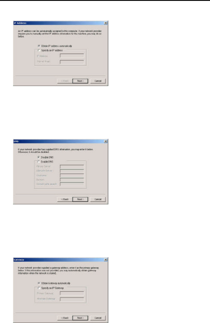
4-2 ADVANCED CONFIGURATION
In the Advanced Configuration menu you may:
Antenna Configuration
Transmit – You may select “Antenna 1”, “Antenna 2” or “Both” if you would like to have both
antenna to perform the same function.
Receive - You may select “Antenna 1”, “Antenna 2” or “Both” if you would like to have both
antenna to perform the same function.
Retry Limits
Short Retries – By default it is set to “7” will be the best number to retry to minimize the
network overhead.
Long Retries – By default it is set to “4” to maximize the network data throughput.
Transmit Power – Select “Automatic” for the device to adjust its Transmit Power or
“Power Level 1” to have power gain on the Transmit Power.
Authentication Method - It can be selected for “Open Authentication” or “Shared Key
Authentication” for the indication of an authentication algorithm. “Shared Key” is to be
selected while the WEP for PC card and Access Point are both enabled and setup with the
same passphrase key. And “Open System” is for disabled WEP in Wireless Network system.
Thresholds -
Fragmentation Threshold: The value indicates how much of the network resources devoted
to recovering packet errors. The value should remain at its default setting of 2346 bytes. If
you have decreased this value and experience high packet error rates, you can increase it
again, but will likely decrease overall network performance.
RTS Threshold: The value should remain on its default setting 2347 bytes. If you encounter
any date flow, only minor modifications are recommended.
Preamble Type: There is the “Long” or “Short” selection to ensure that systems receiving the
information correctly interpret when the data transmission starts. To select “long” Preamble
may be used to minimize overhead and “Long” to maximize the network data throughput. The
default value will be set for “Long”.
37
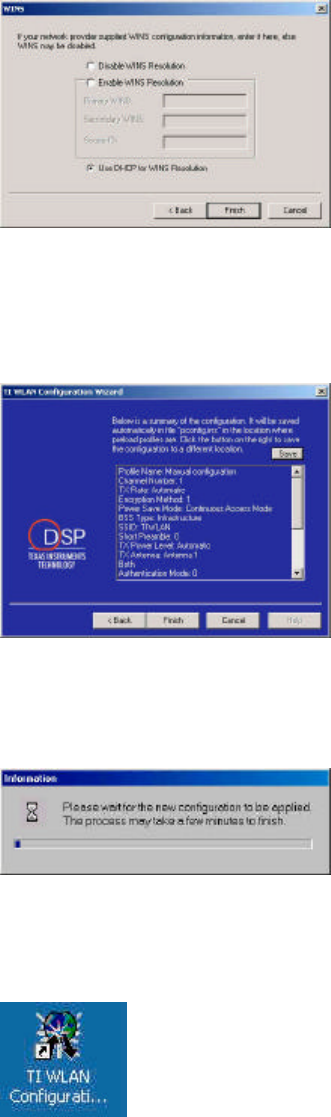
4-3 NETWORK CONFIGURATION
An IP address can be automatically assigned to this computer. If your network provider
requires you to manually set the IP address for this machine, you may do so by click on
“Specify an IP address” then enter the address and the Subnet Mask.
Click “Next” to continue.
If your network provider has supplied DNS information, you may click on “Enable DNS” then
enter the “Primary Server”, “Alternate Server”, “Host Name”, “Domain” name and “Domain
suffix search”.
Click “Next” to continue.
If your network provider supplied a gateway address, enter it as the primary gateway below.
Otherwise the address can automatically obtain from the server when the network starts.
38
If your network provider supplied WINS configuration information, please enter it here or
WINS may remain disabled.
Click “Finish” to continue the configuration.
This is the summary page of the configuration. Everything will be saved in “pconfig.ins” file. If
you would like to save to different location, please click on the “Save” button and specify the
path.
When you click on “Finish”. Windows will try to restart your card to complete the installation.
Double click the icon if you would like to run the configuration again.
39
Appendix A Troubleshooting
Problem Solving
My computer does not recognize the GL242204-0T.
Probable Solution:
§ The GL242204-0T is not properly inserted into the Card Bus slot.
§ Ensure that the GL242204-0T has been inserted into an available Card Bus slot.
The GL242204-0T does not work properly.
Probable Solution:
§ Insert the card into Notebook’s slot again. A beep should be heard if the adapter is
properly inserted.
§ Check the I/O cable that connects the RF module and the card. The power LED indicator
will be active if the cable is properly connected.
§ For non-Windows 95/98 environments, ensure that driver is installed in your computer.
§ 1) Click on the Control Panel and then on PC-Card. Check whether it has the card in one
of the sockets or not. If you find PC-Card Adapter in one of the sockets, it means the card
is detected properly. If you see the yellow sign of
§ question-mark(?), the resources are conflicting.
§ 2)Right click on “My Computer” and the select Properties. Select the device Manager and
click on the Network Adapter. You will find PC-Card Adapter if it is installed successfully.
If you see the Yellow sign the resources are conflicting. Click on and then on service,
you can see the status of. If there are yellow sign either on adapter or, please check
followings.
§ 2-1) Check if your Notebook supports 3.3V card.
§ 2-2)Check if your Notebook has a free IRQ
§ 2-3) Check that you have inserted the right card and have installed the proper driver.
If the GL242204-0T does not function after attempting the above steps, remove the , and do the
following:
§ From the run window enter, c:\windows\system, locate and delete the cw10.sys file
40
§ Open the “Control Panel” double-click “System” and delete PC-card Adapter.
§ Restart the PC and repeat the hardware and software installation steps outlined in
Chapters 3 and 4.
The GL242204-0T station cannot communicate with other computers linked via Ethernet in
the Infrastructure configuration.
Probable Solution:
§ Ensure that the GL242204-0T with which the station is associated is powered on.
§ Confirm the station is configured with the same operating radio channel as the GL242204-
0T. If the IDs are different, change the GL242204-0T and all the stations within the BSS to
another radio channel.
§ Ensure that the station is configured with the same security options as the GL242204-0T,
and can be turned off and on with the same security key.
§ Confirm that the BSS ID is the same as the GL242204-0T for a roaming disabled station.
Alternately confirm that the ESS ID is the same as the GL242204-0T for a roaming enabled
station.
41
Access Point appendix B Glossary
Access Point - An internetworking device that seamlessly connects wired and wireless networks together.
Ad-Hoc - An Ad-Hoc wireless LAN is a group of computers each with wireless adapters, connected as an
independent wireless LAN without an access point to make point-to-point wireless communication.
ATIM – It means "Announcement Traffic Indication Message". A station may enter power save mode if and only if
the value of the ATIM Window in use within the IBSS (in Ad hoc mode) is greater than zero. If this value
is NULL, no power management is used within IBSS created by the station.
Authentication Type – The Authentication Type controls the WEP key validation during the authentication of
a station by the access point. When the Shared Key option is selected, the access point will validate that
the station is using the same WEP key with it. This procedure goes like this: the access point sends a
known unencrypted packet to the station. The station encrypts this packet and sends it back to the
access point. The access point tries to decrypt this packet and then sends an Authentication response
packet to the station indicating the success or failure of this process. On the other hand, under Open
Authentication, there is no check for a matching WEP key.
Backbone - The core infrastructure of a network, the portion of the network that transports information from one
central location to another central location. The information is then off-loaded onto a local system.
Base Station - In mobile telecommunication, a base station is the central radio transmitter/ receiver that
maintains communication with the mobile radio telephone sets within range. In cellular and personal
communications Applications, each cell or micro cell has its own base station; each base station in turn
is interconnected with other cells’ base.
BSS - Stands for “Basic Service Set.” An Access Point associated with several wireless stations.
ESS - Stands for “Extended Service Set.” More than one BSS can be configured as an Extended Service Set. An
ESS is basically a roaming domain.
Ethernet - A popular local area data communications network, originally developed by Xerox Corp., which
accepts transmission from computers and terminals. Ethernet operates on 10 Mbps base band
transmission over shielded coaxial cable or over shielded twisted pair telephone wire.
Fragmentation Threshold – The Fragmentation Threshold defines the number of bytes used for the
fragmentation boundary for directed messages. The purpose of "Fragmentation Threshold" is to
increase the transfer reliability thru cutting a MAC Service Data Unit (MSDU) into several MAC Protocol
Data Units (MPDU) in smaller size. The RF transmission can not allow to transmit too big frame size due
to the heavy interference caused by the big size of transmission frame. But if the frame size is too small,
it will create the overhead during the transmission.
Infrastructure - An integrated wireless and wired LAN system is called an Infrastructure configuration.
Listen Interval – The Listen Interval field is used to indicate to the ACCESS POINT how often a station wakes
to listen to Beacon management frames. The value of this parameter is the station's Listen Interval MIB
attribute and is expressed in units of Beacon Interval. The length of the Listen Interval decides the wake
up time to listen to Beacon management. Longer Listen Interval decreases the performance and shorter
interval decreases power saving function.
PCMCIA - Personal Computer Memory Card International Association, which develops standards for PC cards,
formerly known as s, are available in three “types” which are about the same length and width as credit
cards, but range in thickness from 3.3 mm (Type I) to 5.0 mm (Type II) to 10.5 mm (Type III). These
42
cards can be used for many functions, including memory storage, as landline modems and as wireless
LAN.
Preamble Mode – Preamble is a sequence of bits transmitted at 1Mbps that allows the PHY circuitry to reach
steady-state demodulation and synchronization of bit clock and frame start. Two different preambles and
headers are defined: the mandatory supported Long Preamble and header, which interoperates with the
1 Mbps and 2 Mbps DSSS specification (as described in IEEE Std 802.11), and an optional Short
Preamble and header (as described in IEEE Std 802.11b). At the receiver, the Preamble and header are
processed to aid in demodulation and delivery of the PSDU. The Short Preamble and header may be
used to minimize overhead and, thus, maximize the network data throughput. However, the Short
Preamble is supported only from the IEEE 802.11b (High-Rate) standard and not from the original IEEE
802.11. That means that stations using Short-Preamble cannot communicate with stations implementing
the original version of the protocol.
Roaming - A function that allows one to travel with a mobile end system (wireless LAN mobile station, for
example) through the territory of a domain (an ESS, for example) while continuously connecting to the
infrastructure.
RTS Threshold – Transmitters contending for the medium may not hear each other. The RTS (Request To
Send) Threshold defines the number of bytes used for the RTS/CTS (Clear to Send) handshake
boundary. The small setup value will cause the overhead during the transmission and too big setup
value will decrease the transfer reliability. So normally the value should be default in 2432 bytes. By
inconsistent data flow, try to minor the value. The RTS/CTS mechanism can solve this “ Hidden Node
Problem”.
WEP – Wired Equivalent Privacy (Wep) is an encryption scheme used to protect wireless data communication.
Selecting “Disabled” will prevent you from sharing data with other computers if your network uses Wep.
If your network is Wep enabled, you must choose “64 bits” or “128 bits”. Consult your System
Administrator for more information about your network type. For more information about Wep, see the
Chapter entitled “PRISM Configuration Utility” in this manual.