Global Traffic Technologies OPTICOMGPS5 FHSS Module User Manual Installation manual
Global Traffic Technologies, LLC FHSS Module Installation manual
UserManual.wiki
>
Global Traffic Technologies
>
OPTICOMGPS5 User Manual
Installation manual
Navigation menu
Upload a User Manual
Namespaces
Wiki Guide
HTML
PDF
Info
Views
User Manual
Discussion / Help
Navigation
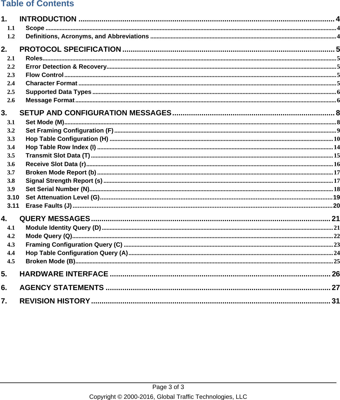
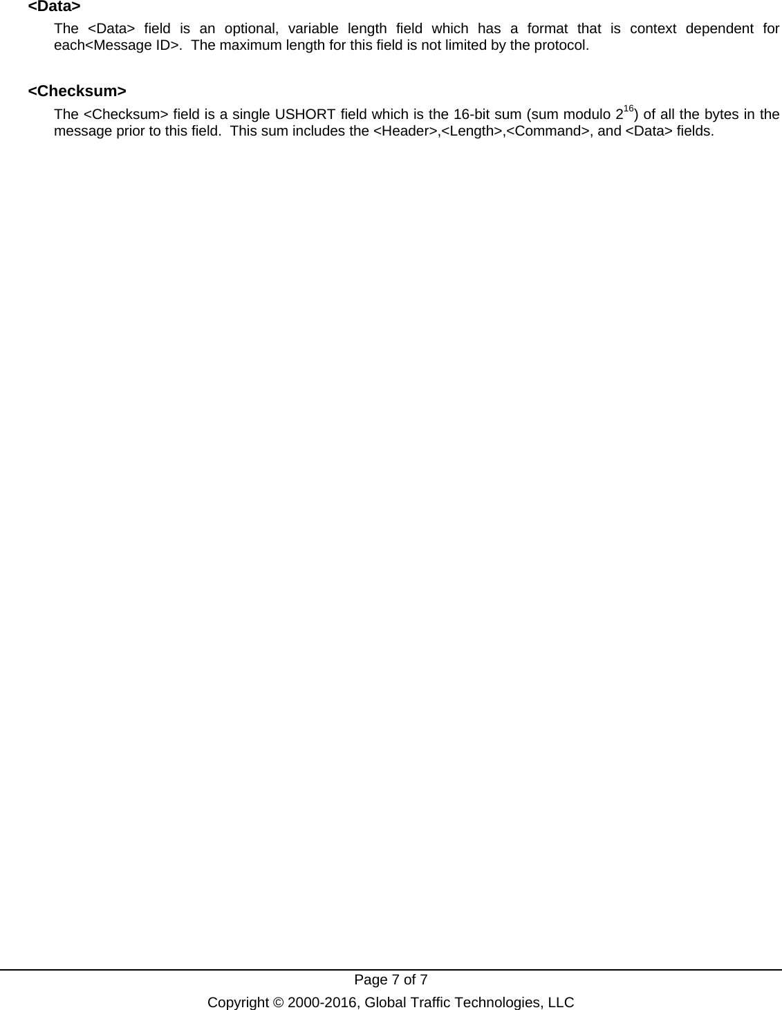
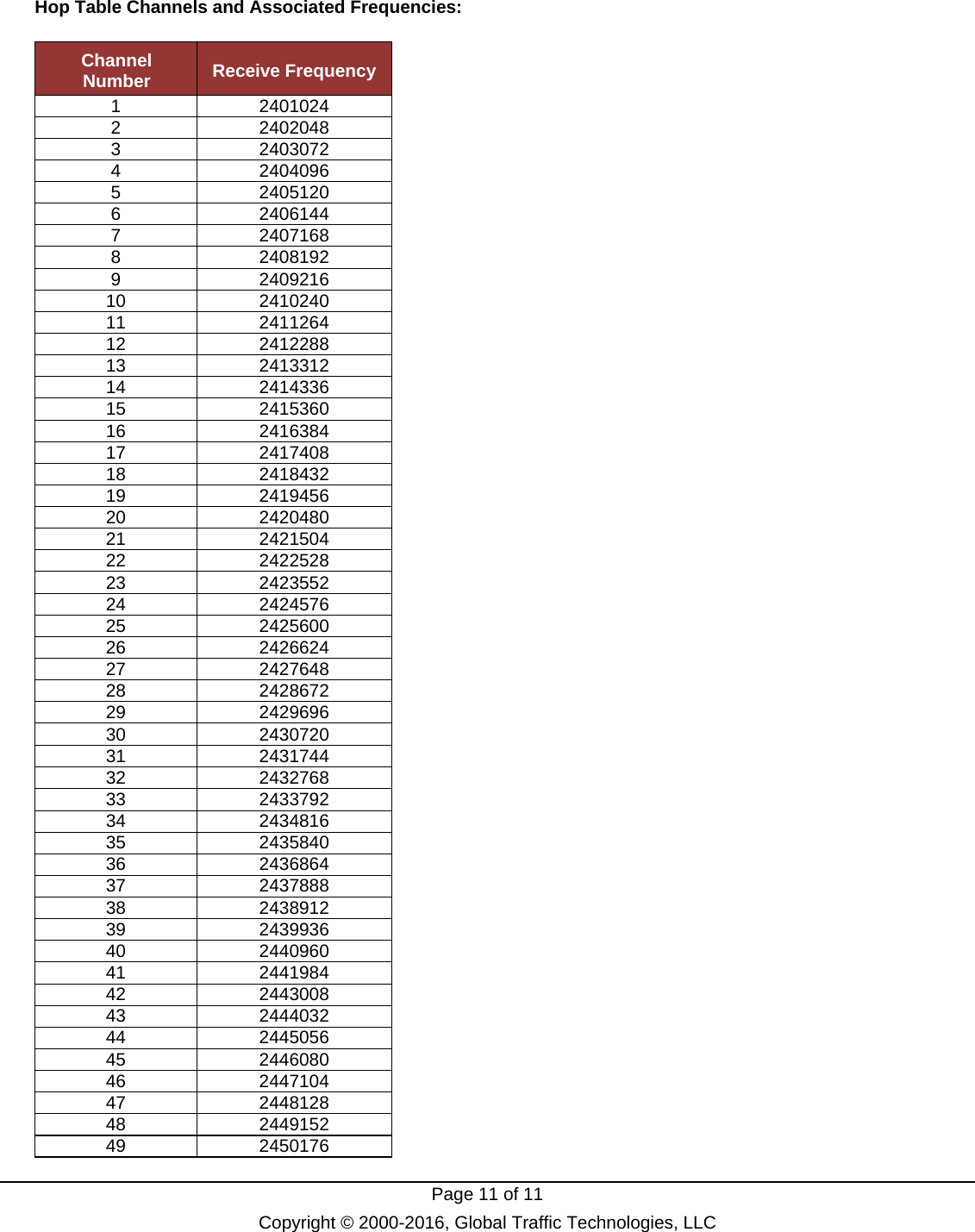
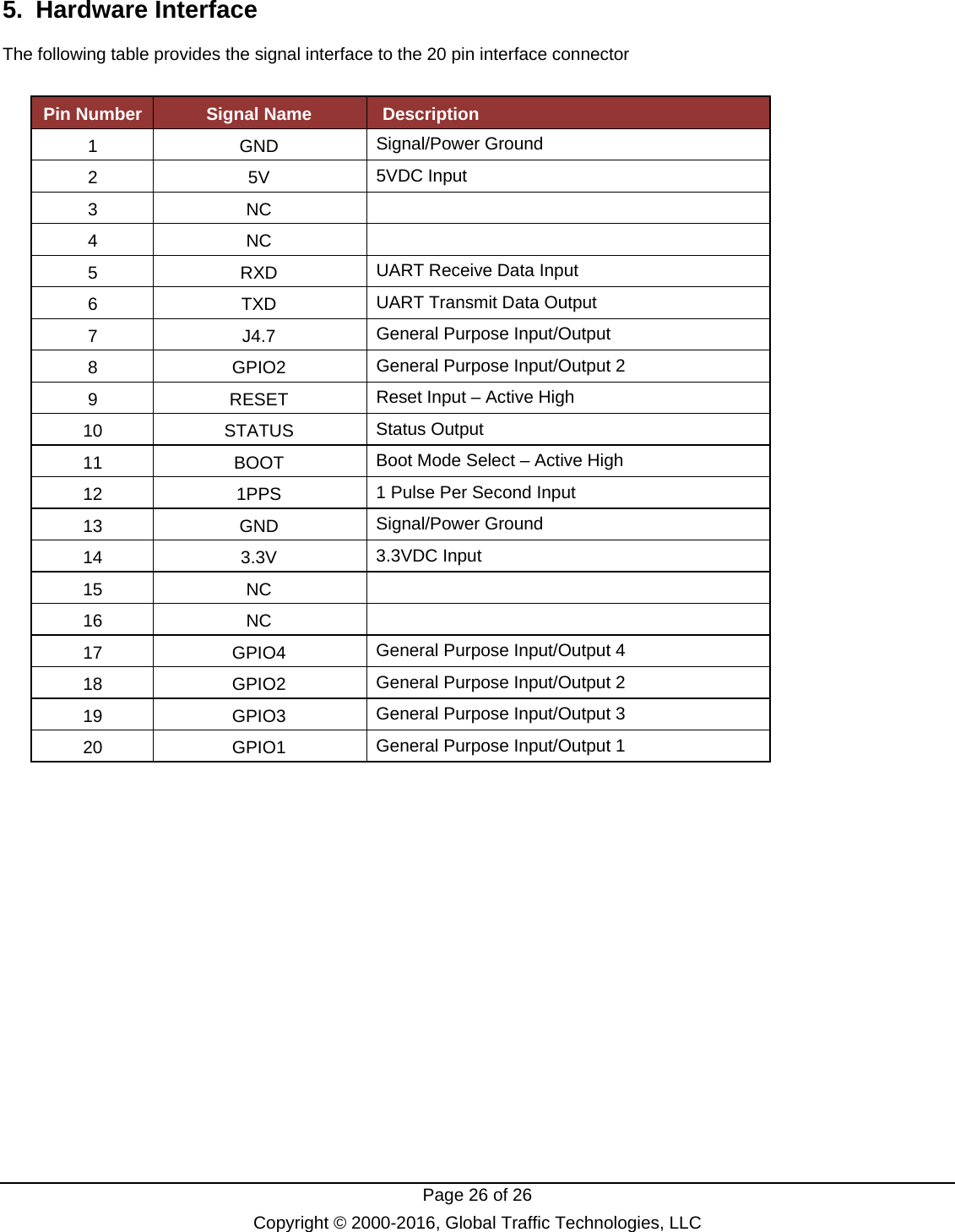
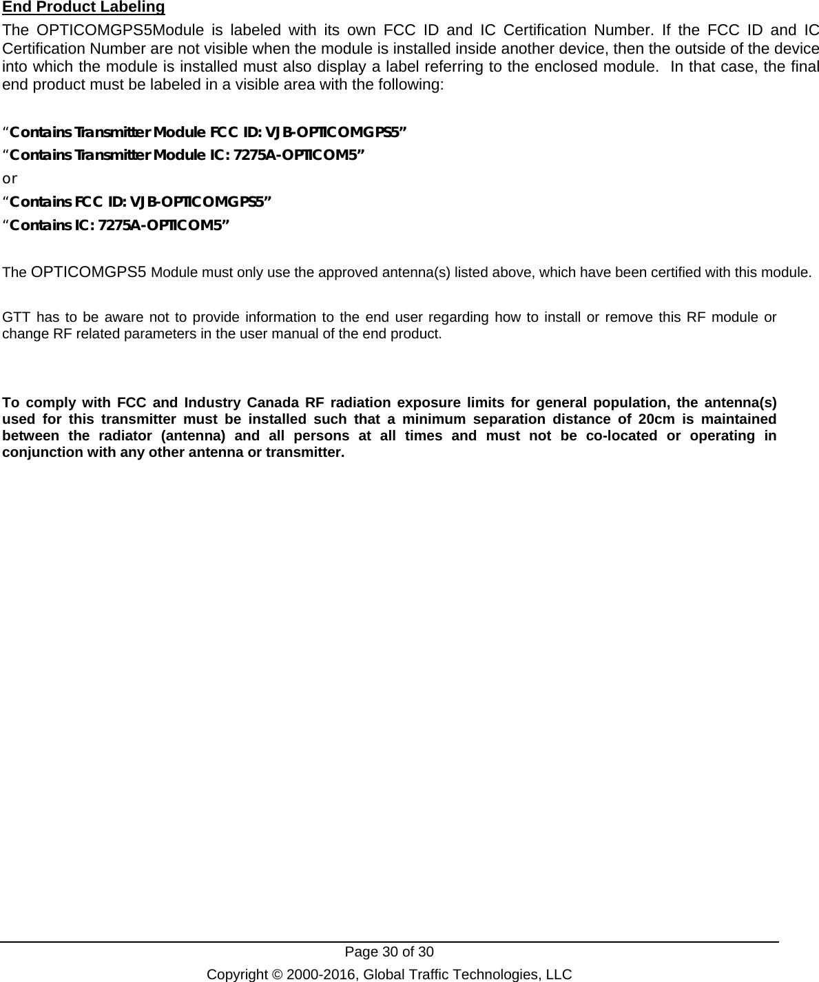
![Page 15 of 15 Copyright © 2000-2016, Global Traffic Technologies, LLC 3.5 Transmit Slot Data (T) The Transmit Slot Data message is used by the host to instruct the RF module on which slot of the slots defined in the Framing Configuration to broadcast the supplied data. The slot, number of bytes and the data are specified. Data is only broadcast for the next time period as defined by the framing configuration. Data must be received by the radio no later than 50 msec prior to the 1PPS. Only 1 TX slot per unit is allowed (i.e. no multiple broadcasts within a single frame). Sent by Host: Data Element Base Type Instances Description Length USHORT 1 Number of bytes to follow including checksum. Value is 6 + value of Size) Command UCHAR 1 Single ASCII character ‘T’ for Transmit Slot Data. Slot UCHAR 1 Must be one of the slots defined in the framing configuration. Range of values is 1 to Number of slots. A value of 0 is not used. Size USHORT 1 Number of bytes to be broadcast. Length is limited by the size of the slot defined in the framing configuration and the maximum size for a single transmission. The size will be the width of the slot. If the data Data UCHAR[Size] 1 Data to be broadcast. First byte [index 0] is first to be broadcast over the air. Sent by RF Module: Data Element Base Type Instances Description Length USHORT 1 Number of bytes to follow including checksum. Always 4 for this message. Command UCHAR 1 Single ASCII character ‘t’ for Transmit Slot Data acknowledgement. Status UCHAR 1 Values are: 0 – Accepted 1 – Invalid slot 2 – Invalid size](https://usermanual.wiki/Global-Traffic-Technologies/OPTICOMGPS5/User-Guide-3715980-Page-15.png)
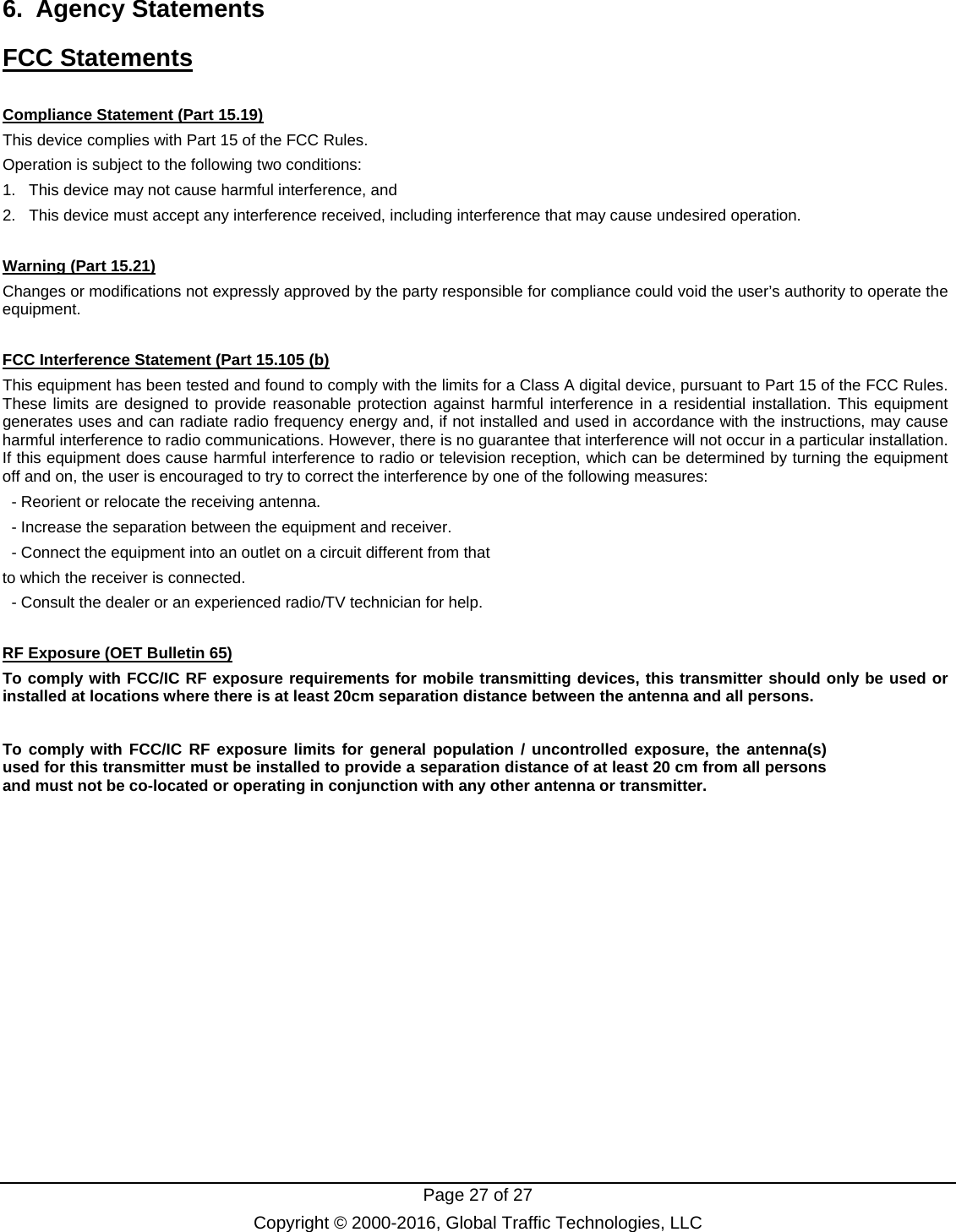
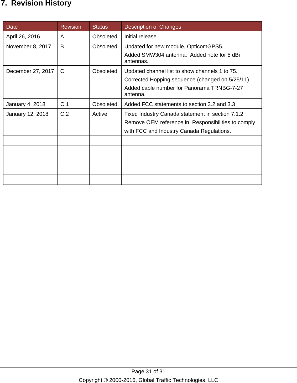
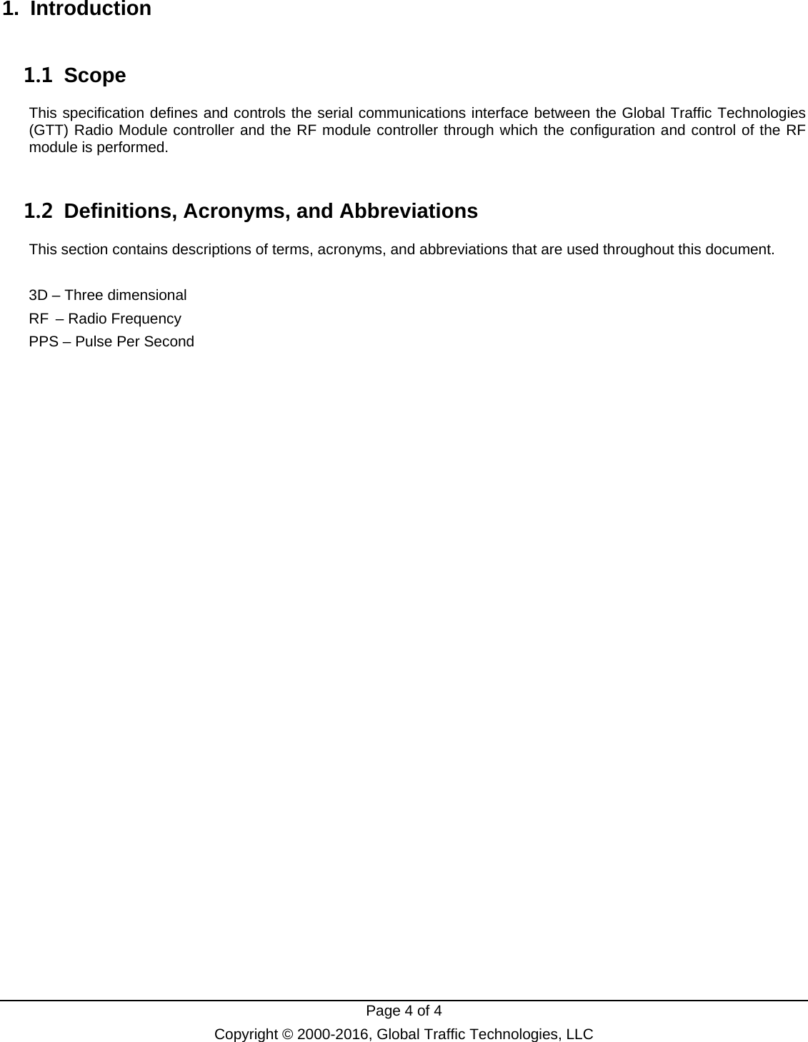
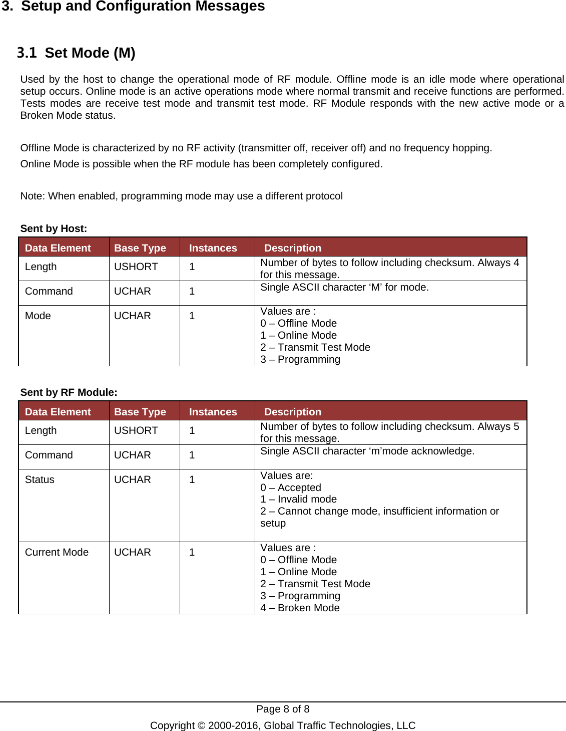
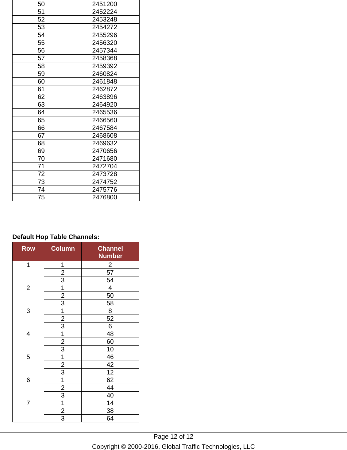
![Page 16 of 16 Copyright © 2000-2016, Global Traffic Technologies, LLC 3.6 Receive Slot Data (r) A Receive Slot Data message is sent at the conclusion of each slot regardless of whether data was received or not. If no data was received, then the Size field specifies 0, the data field is omitted, the received CRC is 0, the calculated CRC is 0, and the RSSI is the valued that was sampled during the slot. Sent by RF Module: Data Element Base Type Instances Description Length USHORT 1 Number of bytes to follow including checksum. Value is 12 + value of Size). Command UCHAR 1 Single ASCII character ‘r’ for Receive Slot Data. Slot UCHAR 1 Must be one of the slots defined in the framing configuration. Size USHORT 1 Number of bytes received. Length is limited by the size of the slot defined in the framing configuration. Data UCHAR[Size] 1 Data received. . First byte [index 0] is first to be received over the air. Field is omitted if length is 0. TX CRC USHORT 1 Transmitted CRC. Calculated by transmitter. RX CRC USHORT 1 Calculated CRC on the receive side. RSSI UCHAR 1 Received Signal strength indicator. SNR UCHAR 1 Approximation of Signal to noise ration 0-255 representing 0-25.5 dB. At 10 dB, running at .01 BER. Sent by Host: No acknowledgement. Assumed that new data will with the next frequency hop.](https://usermanual.wiki/Global-Traffic-Technologies/OPTICOMGPS5/User-Guide-3715980-Page-16.png)
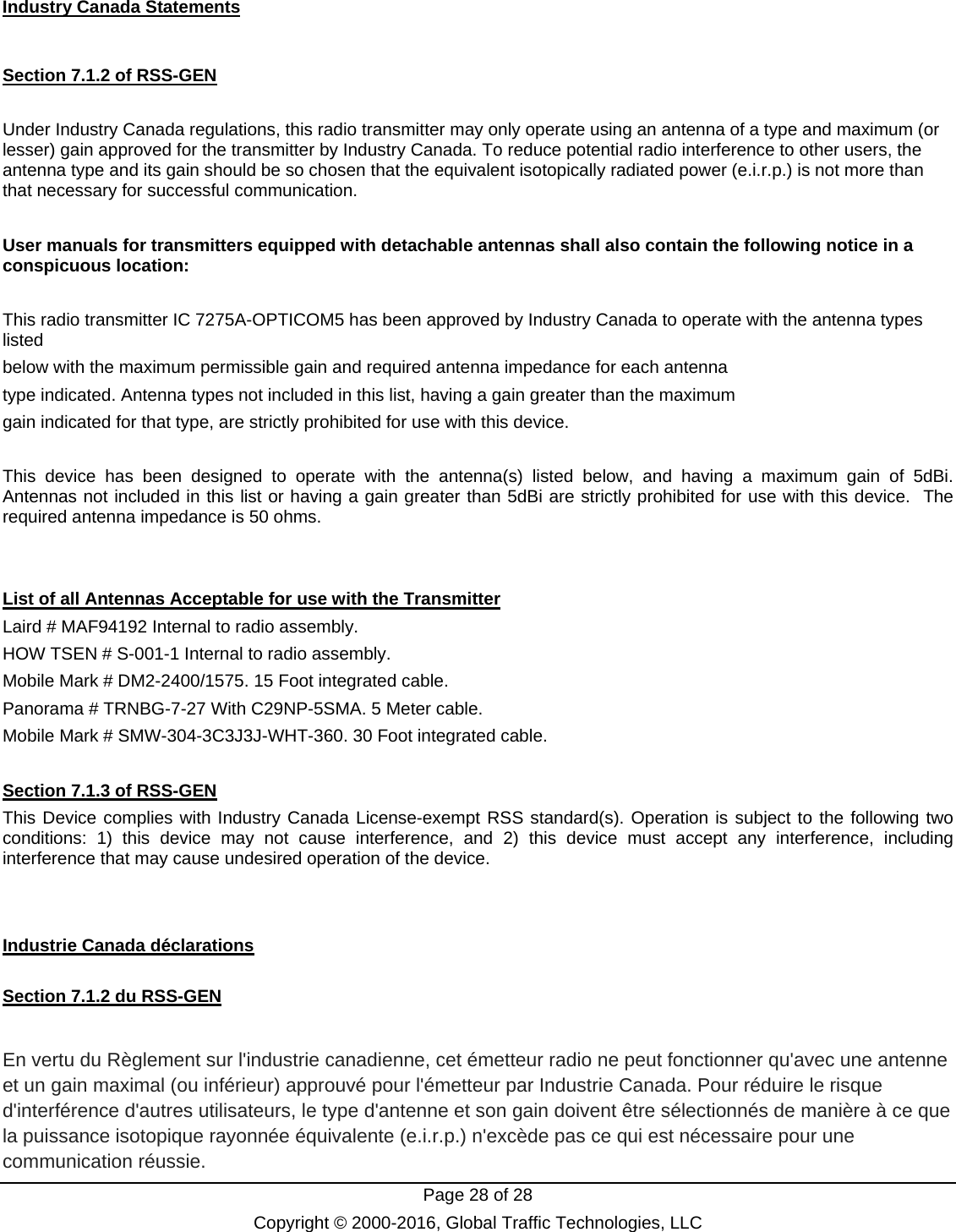
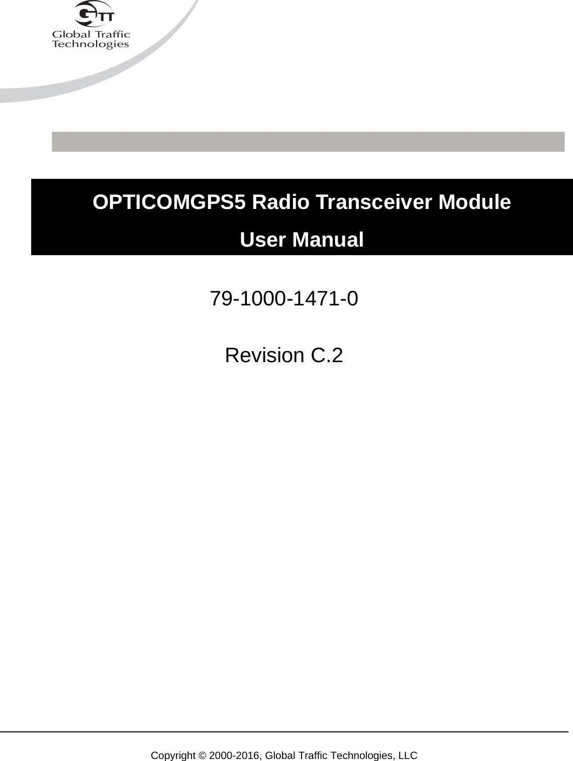
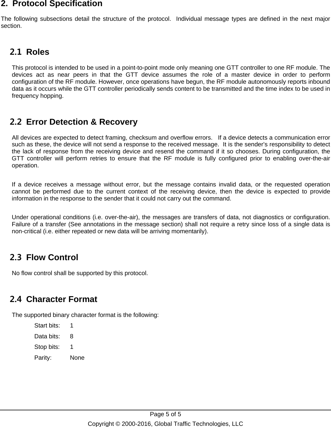
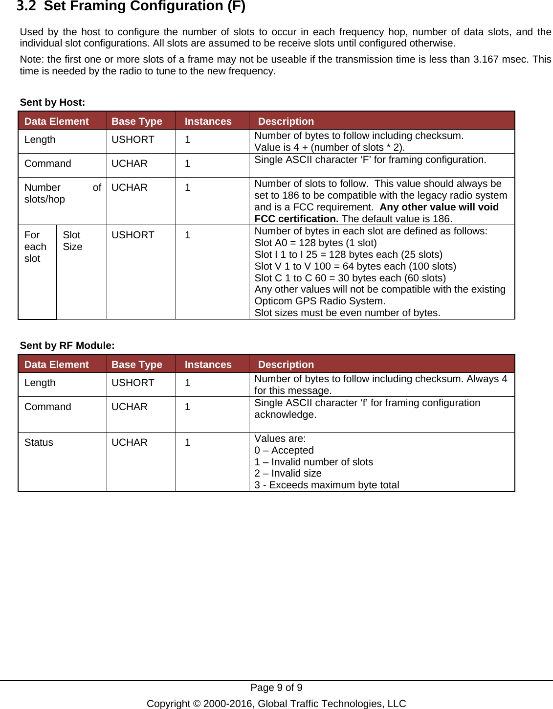
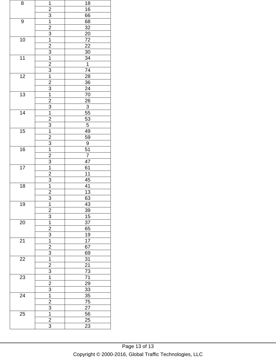
![Page 18 of 18 Copyright © 2000-2016, Global Traffic Technologies, LLC 3.9 Set Serial Number (N) Used by the host controller to set the radio module’s serial number. Sent by Host: Data Element Base Type Instances Description Length USHORT 1 Number of bytes to follow including checksum. Always 13 for this message. Command UCHAR 1 Single ASCII character ‘N’ for Set Serial Number. Serial Number UCHAR[10] 1 Format is: RAyywwssss where RA denotes RF module with OMAP processor (dual core) yy demotes the last two digits of the year and ww is the week since the beginning of the year and ssss is the sequence number as labeled on the radio board. RByywwssss denotes RF module with TMS processor (single core).The yy, ww and ssss fields are the same. Sent by RF Module: Data Element Base Type Instances Description Length USHORT 1 Number of bytes to follow including checksum. Always 3 for this message. Command UCHAR 1 Single ASCII character ‘n’ for Set Serial Number acknowledge.](https://usermanual.wiki/Global-Traffic-Technologies/OPTICOMGPS5/User-Guide-3715980-Page-18.png)
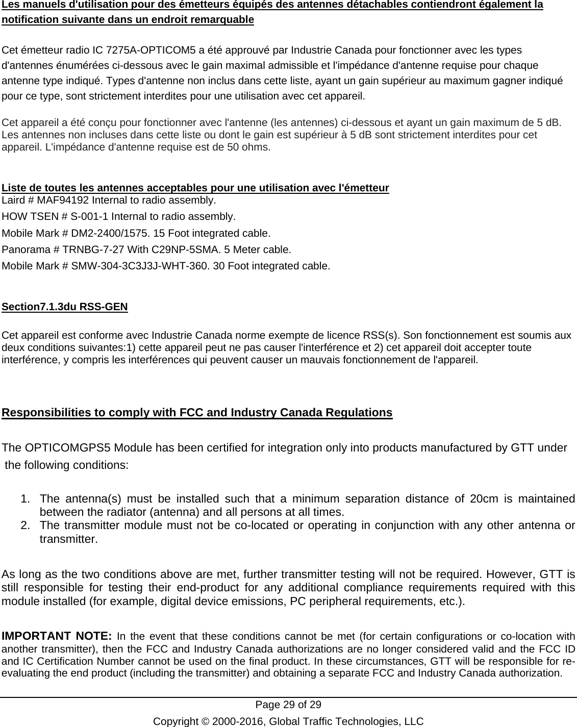
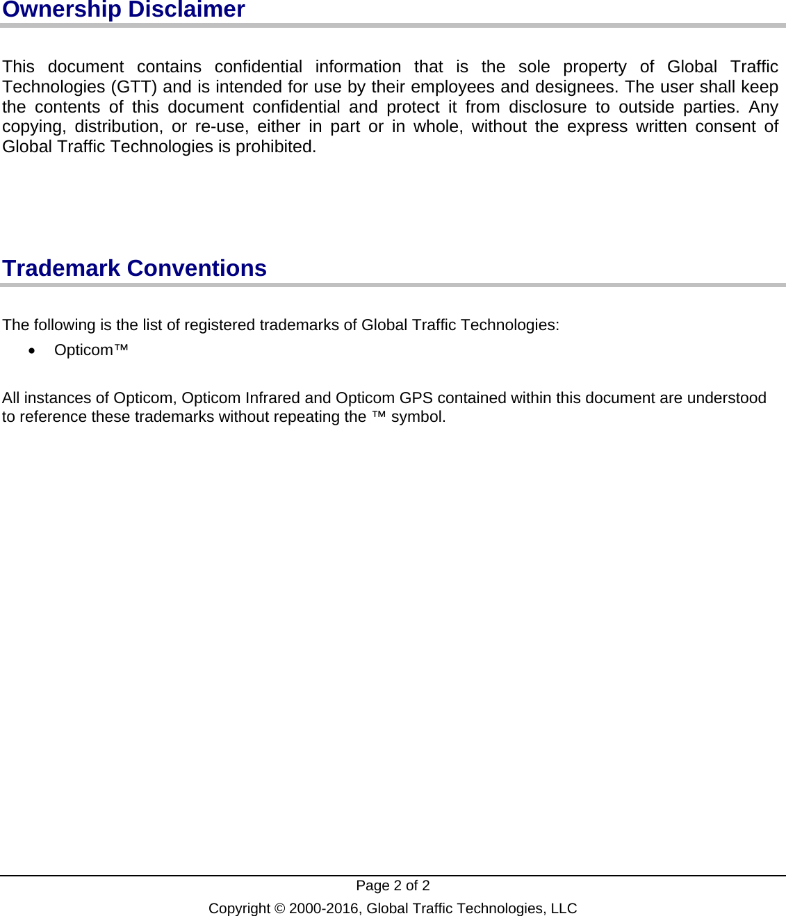
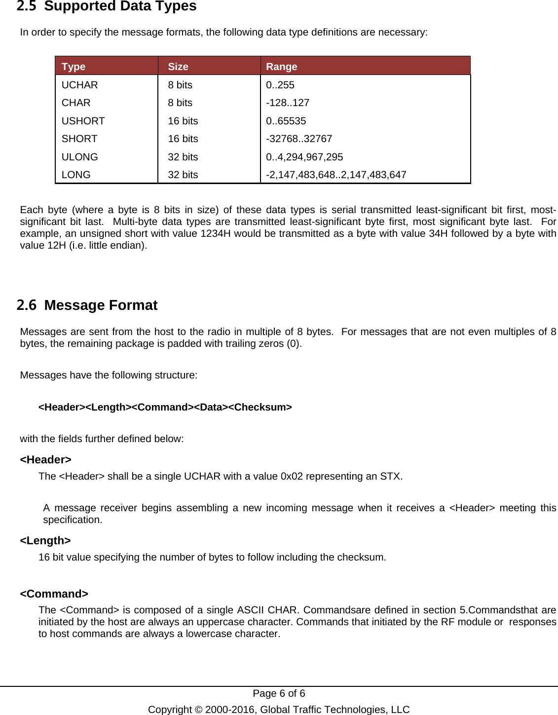
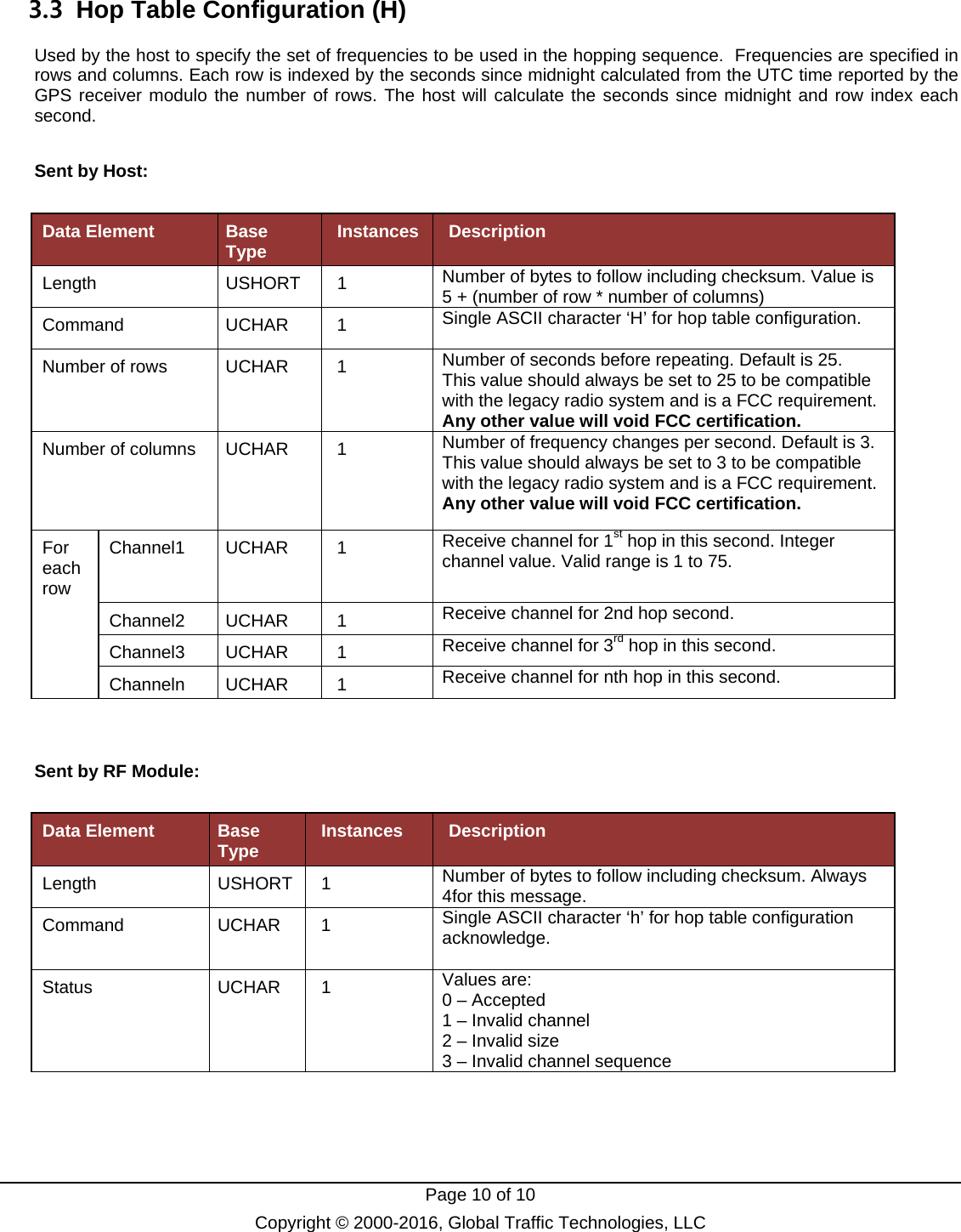
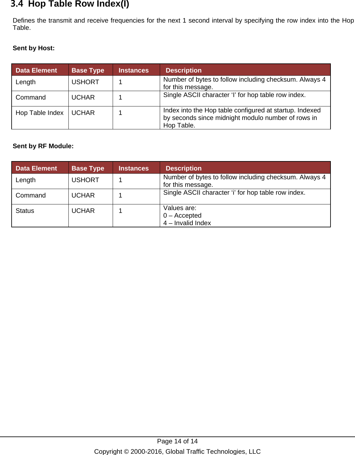
![Page 21 of 21 Copyright © 2000-2016, Global Traffic Technologies, LLC 4. Query Messages 4.1 Module Identity Query (D) Used by the host controller to query the make/model and firmware revision of the unit. Sent by Host: Data Element Base Type Instances Description Length USHORT 1 Number of bytes to follow including checksum. Always 3 for this message. Command UCHAR 1 Single ASCII character ‘D’ for Query Identity. Sent by RF Module: Data Element Base Type Instances Description Length USHORT 1 Number of bytes to follow including checksum. Always 22 for this message. Command UCHAR 1 Single ASCII character ‘d’ for Identity acknowledge. Serial Number UCHAR[10] 1 Format is: RMssssssss where RM denotes RF module and ssssssss is the sequence number as labeled on the radio board. Refer to GTT Serial Number Format specification 79-1000-0205-0 Firmware Revision UCHAR[9] 1 ASCII string representing the revision string. Format is: XX.XX .XXX Leading zeros to be supplied if single digit version number.](https://usermanual.wiki/Global-Traffic-Technologies/OPTICOMGPS5/User-Guide-3715980-Page-21.png)