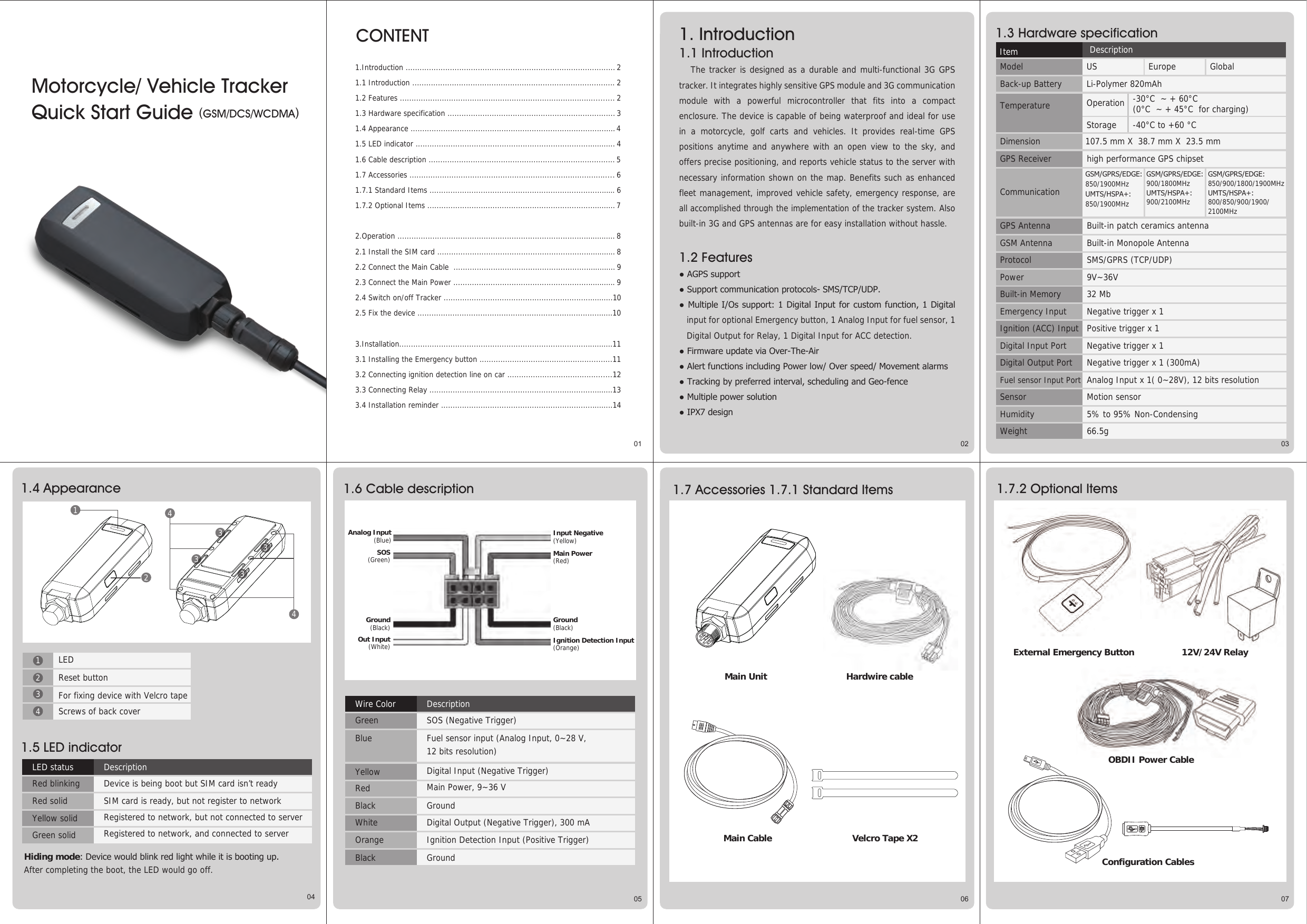
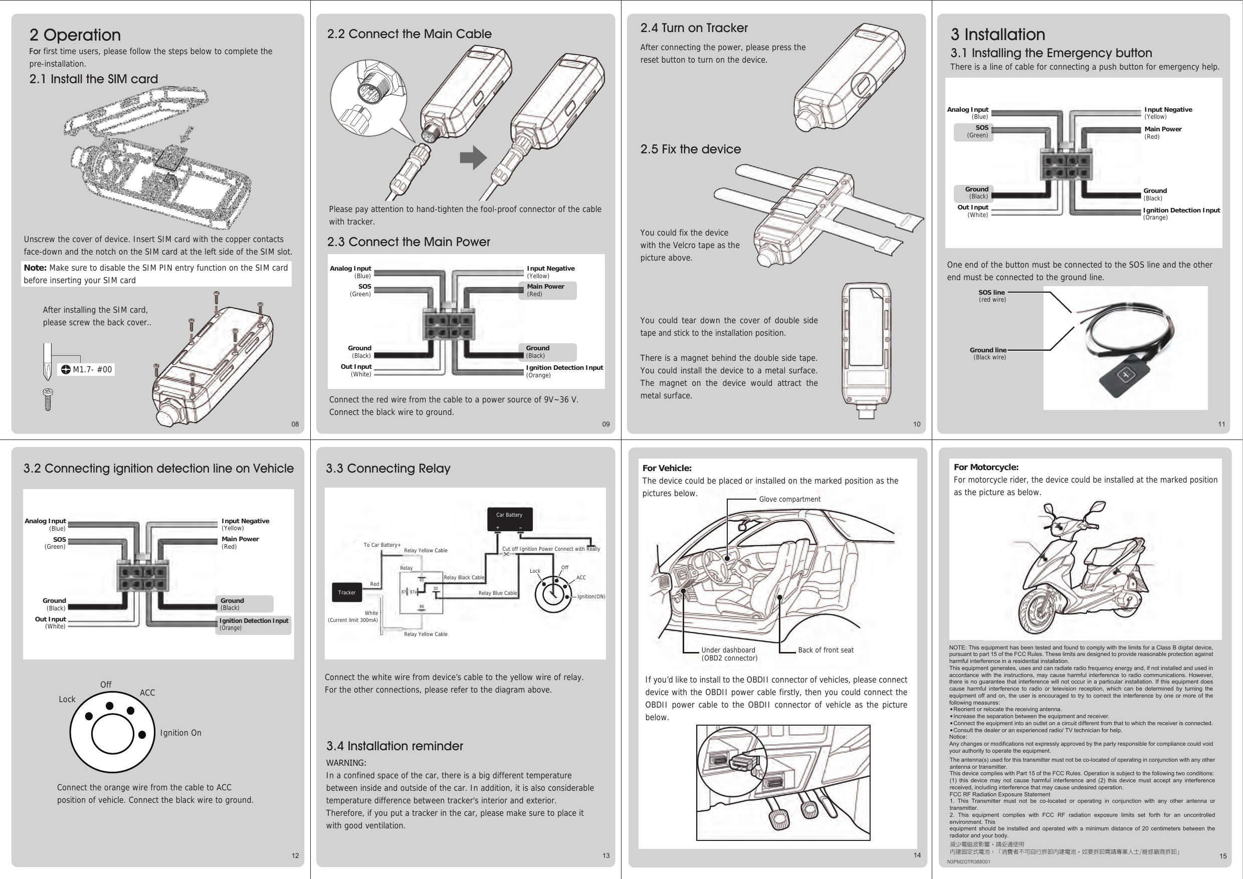
GlobalSat WorldCom GTR-388 Motorcycle/ Vehicle Tracker User Manual GTR 388 QSG N3PM2GTR388001 T2 0 1109

GlobalSat WorldCom Corporation Motorcycle/ Vehicle Tracker GTR 388 QSG N3PM2GTR388001 T2 0 1109

User Manual

01 02 030504 06 07Model US Europe Global Item DescriptionTemperature-40°C to +60 °CIgnition (ACC) Input Positive trigger x 1Digital Input Port Negative trigger x 1Digital Output Port Negative trigger x 1 (300mA)Fuel sensor Input Port Analog Input x 1( 0~28V), 12 bits resolutionSensor Motion sensorHumidityWeight5% to 95% Non-Condensing-30°C  ~ + 60°C (0°C  ~ + 45°C  for charging)Back-up Battery Li-Polymer 820mAhCONTENTDimension 107.5 mm X  38.7 mm X  23.5 mmGPS Receiver high performance GPS chipsetCommunicationGPS Antenna Built-in patch ceramics antennaGSM Antenna Built-in Monopole AntennaProtocol SMS/GPRS (TCP/UDP)Power 9V~36VBuilt-in Memory 32 Mb 66.5gEmergency Input Negative trigger x 1Analog Input(Blue)SOS(Green)Ground(Black)Out Input(White)Input Negative(Yellow)Main Power(Red)Ignition Detection Input (Orange)Ground(Black)Motorcycle/ Vehicle Tracker Quick Start Guide (GSM/DCS/WCDMA) 1. Introduction1.1 Introduction   The tracker is designed as a durable and multi-functional 3G GPS tracker. It integrates highly sensitive GPS module and 3G communication module with a powerful microcontroller that fits into a compact enclosure. The device is capable of being waterproof and ideal for use in a motorcycle, golf carts and vehicles. It provides real-time GPS positions anytime and anywhere with an open view to the sky, and offers precise positioning, and reports vehicle status to the server with necessary information shown on the map. Benefits such as enhanced fleet management, improved vehicle safety, emergency response, are all accomplished through the implementation of the tracker system. Also built-in 3G and GPS antennas are for easy installation without hassle.1.2 Features● AGPS support● Support communication protocols- SMS/TCP/UDP.● Multiple I/Os support: 1 Digital Input for custom function, 1 Digital input for optional Emergency button, 1 Analog Input for fuel sensor, 1 Digital Output for Relay, 1 Digital Input for ACC detection.● Firmware update via Over-The-Air● Alert functions including Power low/ Over speed/ Movement alarms ● Tracking by preferred interval, scheduling and Geo-fence● Multiple power solution● IPX7 design1.3 Hardware specification1.4 Appearance 1.6 Cable description 1.7 Accessories 1.7.1 Standard Items 1.7.2 Optional Items1.5 LED indicatorGSM/GPRS/EDGE: 850/1900MHz UMTS/HSPA+:850/1900MHz GSM/GPRS/EDGE:900/1800MHz UMTS/HSPA+:900/2100MHz GSM/GPRS/EDGE:850/900/1800/1900MHz UMTS/HSPA+:800/850/900/1900/2100MHz OperationStorage114433333422LEDLED statusRed blinkingRed solidYellow solidGreen solidDescriptionReset buttonFor fixing device with Velcro tapeDevice is being boot but SIM card isn’t ready SIM card is ready, but not register to network Registered to network, but not connected to server Registered to network, and connected to server Wire ColorGreenBlueYellowRedBlackWhiteOrangeBlackDescriptionSOS (Negative Trigger)Fuel sensor input (Analog Input, 0~28 V, 12 bits resolution) Digital Input (Negative Trigger)Main Power, 9~36 VGroundDigital Output (Negative Trigger), 300 mAIgnition Detection Input (Positive Trigger)GroundScrews of back coverHiding mode: Device would blink red light while it is booting up. After completing the boot, the LED would go off. Main UnitVelcro Tape X2Hardwire cableExternal Emergency Button 12V/24V RelayConfiguration Cables1.Introduction .......................................................................................... 21.1 Introduction ....................................................................................... 21.2 Features ............................................................................................ 21.3 Hardware specification ........................................................................ 31.4 Appearance ........................................................................................ 41.5 LED indicator ...................................................................................... 41.6 Cable description ................................................................................ 51.7 Accessories ........................................................................................ 61.7.1 Standard Items ................................................................................ 61.7.2 Optional Items ................................................................................. 72.Operation .............................................................................................. 82.1 Install the SIM card ............................................................................. 82.2 Connect the Main Cable  ...................................................................... 92.3 Connect the Main Power ...................................................................... 92.4 Switch on/off Tracker .........................................................................102.5 Fix the device ....................................................................................103.Installation............................................................................................113.1 Installing the Emergency button .........................................................113.2 Connecting ignition detection line on car .............................................123.3 Connecting Relay ...............................................................................133.4 Installation reminder ..........................................................................14OBDII Power CableMain Cable
09 10 1113 1312 14 15One end of the button must be connected to the SOS line and the other end must be connected to the ground line. Connect the white wire from device’s cable to the yellow wire of relay. For the other connections, please refer to the diagram above. Cut off Ignition Power Connect with Really08SOS line (red wire)Ground line(Black wire)LockOff ACCIgnition OnTo Car Battery+ Relay Yellow CableRelay Black CableRedWhite(Current limit 300mA)Relay Yellow CableRelayRelay Blue CableLock ACCOfflgnition(ON)TrackerCar Battery+8587 87a 3086N3PM2GTR388000Unscrew the cover of device. Insert SIM card with the copper contacts face-down and the notch on the SIM card at the left side of the SIM slot.  Note: Make sure to disable the SIM PIN entry function on the SIM card before inserting your SIM cardAfter installing the SIM card, please screw the back cover..Connect the orange wire from the cable to ACC position of vehicle. Connect the black wire to ground.  15For Motorcycle:For motorcycle rider, the device could be installed at the marked position as the picture as below.3.4 Installation reminderWARNING:In a confined space of the car, there is a big different temperature between inside and outside of the car. In addition, it is also considerable temperature difference between tracker's interior and exterior. Therefore, if you put a tracker in the car, please make sure to place it with good ventilation. Under dashboard(OBD2 connector) Back of front seatGlove compartmentN3PM2GTR388001If you’d like to install to the OBDII connector of vehicles, please connect device with the OBDII power cable firstly, then you could connect the OBDII power cable to the OBDII connector of vehicle as the picture below. NOTE: This equipment has been tested and found to comply with the limits for a Class B digital device, pursuant to part 15 of the FCC Rules. These limits are designed to provide reasonable protection against harmful interference in a residential installation.This equipment generates, uses and can radiate radio frequency energy and, if not installed and used in accordance with the  instructions,  may cause  harmful  interference to  radio  communications. However, there is no guarantee that interference will  not occur in  a particular installation.  If this equipment does cause  harmful  interference  to  radio  or  television  reception,  which  can  be  determined  by  turning  the equipment off and on, the user is encouraged to try to correct the interference by one or more of the following measures:  ●  Reorient or relocate the receiving antenna.  ●  Increase the separation between the equipment and receiver.  ●  Connect the equipment into an outlet on a circuit different from that to which the receiver is connected.  ●  Consult the dealer or an experienced radio/ TV technician for help.Notice: Any changes or modifications not expressly approved by the party responsible for compliance could void your authority to operate the equipment. For Vehicle: The device could be placed or installed on the marked position as the pictures below. 減少電磁波影響,請妥適使用內建固定式電池:「消費者不可自行拆卸內建電池,如要拆卸需請專業人士/維修廠商拆卸」The antenna(s) used for this transmitter must not be co-located of operating in conjunction with any other antenna or transmitter. This device complies with Part 15 of the FCC Rules. Operation is subject to the following two conditions: (1)  this  device  may  not  cause  harmful  interference  and  (2)  this  device  must  accept  any  interference received, including interference that may cause undesired operation.FCC RF Radiation Exposure Statement1.  This  Transmitter  must  not  be  co-located  or  operating  in  conjunction  with  any  other  antenna  or transmitter.2.  This  equipment  complies  with  FCC  RF  radiation  exposure  limits  set  forth  for  an  uncontrolled environment. Thisequipment  should  be  installed  and operated with a minimum distance  of  20  centimeters  between  the radiator and your body.  2 Operation For first time users, please follow the steps below to complete the pre-installation. 2.1 Install the SIM card 3 Installation3.1 Installing the Emergency buttonThere is a line of cable for connecting a push button for emergency help.2.5 Fix the device2.4 Turn on TrackerAfter connecting the power, please press the reset button to turn on the device.3.2 Connecting ignition detection line on Vehicle3.3 Connecting RelayYou could fix the device with the Velcro tape as the picture above.You could tear down the cover of double side tape and stick to the installation position. There is a magnet behind the double side tape. You could install the device to a metal surface. The magnet on the device would attract the metal surface.Analog Input(Blue)SOS(Green)Input Negative(Yellow)Main Power(Red)Analog Input(Blue)SOS(Green)Input Negative(Yellow)Main Power(Red)Analog Input(Blue)SOS(Green)Input Negative(Yellow)2.3 Connect the Main PowerConnect the red wire from the cable to a power source of 9V~36 V. Connect the black wire to ground.  Main Power(Red)M1.7- #002.2 Connect the Main CableGround(Black)Out Input(White) Ignition Detection Input (Orange)Ground(Black)14Ground(Black)Out Input(White) Ignition Detection Input (Orange)Ground(Black)Ground(Black)Out Input(White)Ignition Detection Input (Orange)Ground(Black)Please pay attention to hand-tighten the fool-proof connector of the cable with tracker.

Navigation menu