GlobalSat WorldCom GTR129 Motorcycle/Vehicle Tracker User Manual GTR 128 GTR 129 QSG 20121101

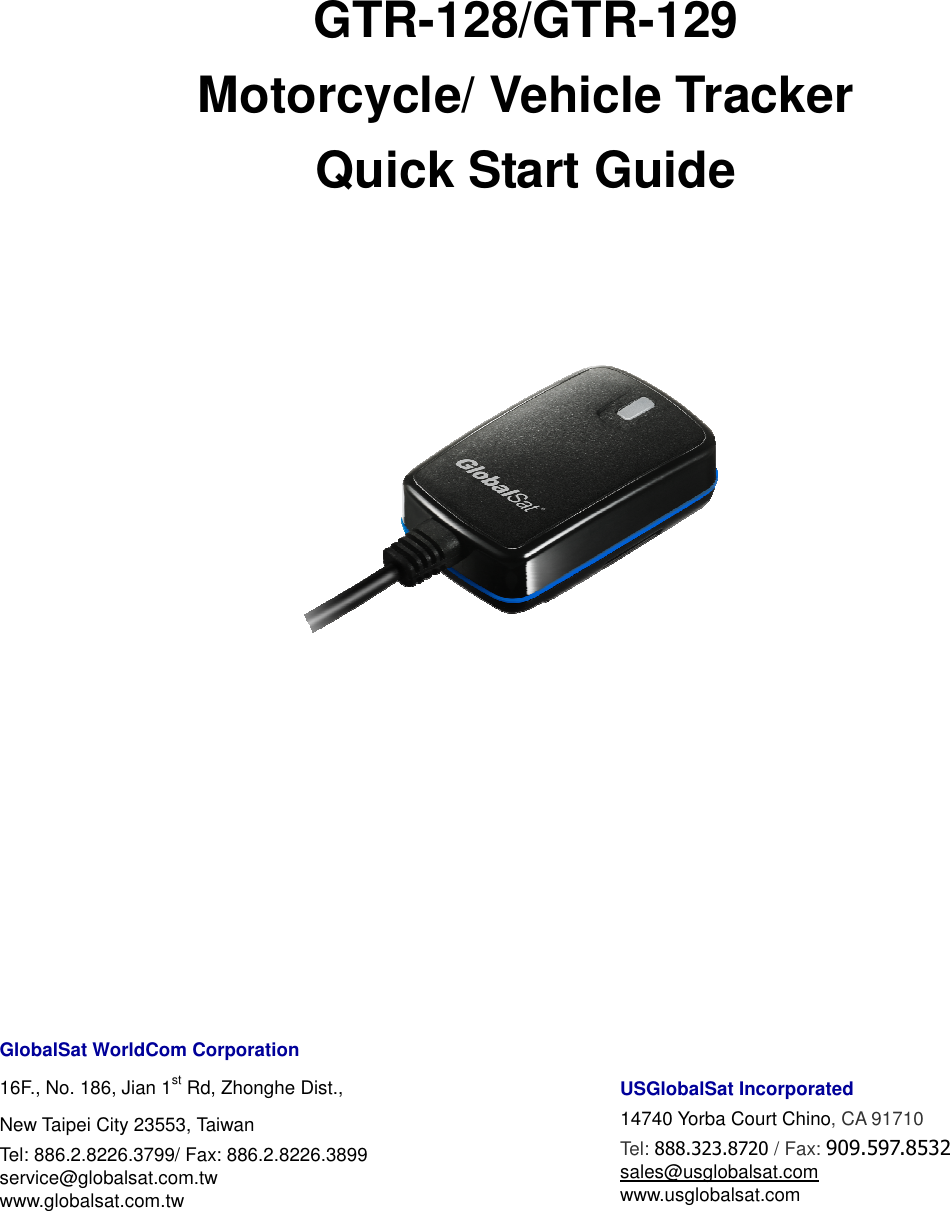
GlobalSat WorldCom Corporation Motorcycle/Vehicle Tracker GTR 128 GTR 129 QSG 20121101

User Manual

    GTR-128/GTR-129 Motorcycle/ Vehicle Tracker Quick Start Guide           GlobalSat WorldCom Corporation 16F., No. 186, Jian 1st Rd, Zhonghe Dist.,   New Taipei City 23553, Taiwan   Tel: 886.2.8226.3799/ Fax: 886.2.8226.3899 service@globalsat.com.tw www.globalsat.com.tw      USGlobalSat Incorporated 14740 Yorba Court Chino, CA 91710 Tel: 888.323.8720 / Fax: 909.597.8532 sales@usglobalsat.com www.usglobalsat.com
  2 CONTENT  1. Introduction ........................................................................................................................ 3 1.1 Introduction ............................................................................................................... 3 1.2 Features ..................................................................................................................... 3 1.3 Hardware specification ............................................................................................ 4 1.4 Appearance ................................................................................................................ 5 1.5 LED indicator ............................................................................................................. 5 1.6 Cable description ...................................................................................................... 6 1.7 Accessories ................................................................................................................ 7 1.7.1 Standard Items ........................................................................................................... 7 1.7.2 Optional Items ............................................................................................................ 8 12V/24V Relay .................................................................................................................... 8 2 Operation .............................................................................................................................. 9 2.1 Install the SIM card ................................................................................................. 9 2.2 Connect the Main Power ........................................................................................ 11 2.3 Switch on/off Tracker ............................................................................................. 11 2.4 Fix the device .......................................................................................................... 12 3 Installation.......................................................................................................................... 14 3.1 Installing the Emergency button ......................................................................... 14 3.2 Connecting ignition detection line on car .......................................................... 15 3.3 Connecting Relay .................................................................................................... 16 3.4 Installation reminder ............................................................................................. 17
  3  1. Introduction  1.1 Introduction GTR-128/GTR-129 is designed as a durable and multi-functional GPS/GSM/GPRS tracker. It integrates  highly sensitive GPS module and  quad-band  GSM communication  module with  a powerful  microcontroller  that  fits  into  a  compact  enclosure.  The  device  is  capable  of  being waterproof and ideal for use in a motorcycle, golf carts and vehicles. It is small in size and low in cost for covert and efficient tracking device. It provides real-time GPS positions anytime and anywhere with an open view to the sky, and offers precise positioning, and reports vehicle status to the server with necessary information shown on the map. Benefits such as enhanced fleet management, improved vehicle safety, emergency response, are all accomplished through the implementation of the GTR-128/GTR-129 system. The built-in GSM and GPS antennas are for easy installation without hassle.    1.2 Features   New generation GPS module.   Compact and Waterproof IP67 design     Built-in high sensitivity GPS/GSM antennas.   Quad-Band GSM System     Built-in motion sensor   AGPS support   Support communication protocols- SMS/TCP/UDP.   Multiple I/Os support: 1 Digital Input for custom function, 1 Digital input for optional Emergency button, 1 Analog Input for fuel sensor, 1 Digital Output for Relay, 1 Digital Input for ACC detection.   Configuration and Firmware update via Over-The-Air   Alert functions including Power low/ Over speed/ Movement alarms   Tracking by preferred interval, scheduling and Geo-fence   With magnet (GTR-128) or double side tape (GTR-129) for easy installation   Multiple power solution
  4   1.3 Hardware specification  Item  Description Model  GTR-128  GTR-129 Back-up Battery  No back-up battery, but magnetic mount instead Li-Polymer 320mAh Unit Weight  77g  78.5g Temperature  Operation  -30℃ ~ + 70℃  -30℃ ~ + 60℃           (0℃ ~ + 45℃ for charging) Storage  -40℃ ~ + 70℃  -40℃ ~ + 60℃ Dimension  61 mm X 38 mm X 19 mm GPS receiver    high performance GPS chipset   Communication  Quad-Band GSM (850/900/1800/1900 MHz) GPS Antenna  Built-in patch ceramics antenna GSM Antenna  Built-in Pi-Fa antenna Protocol  SMS/GPRS (TCP/UDP) Power  +9~36 V Built-in Memory  32 Mb   Emergency Input    Negative trigger x 1 Ignition (ACC) Input    Positive trigger x 1 Digital Input Port  Negative trigger x 1 Digital Output Port  Negative trigger x 1 (300 mA) Fuel sensor Input Port  Analog Input x 1( 0~28V), 12 bits resolution Sensor  Motion sensor Humidity  5% to 95% Non-Condensing
  5 1.4 Appearance        1  LED 2  For fixing device with Velcro tape   3  Hook for screw/ unscrew back cover   1.5 LED indicator   Normal mode: LED status    Description Red blinking  Device is being boot and SIM card not ready Red solid  SIM card ready, but GSM not registered Yellow solid  GSM registered, but GPRS not connected Green solid  GSM registered, and GPRS connected  Hiding mode: Device would blink red light while it is booting up. After completing the boot, the LED would go off.     1 2 2 3
  6 1.6 Cable description   Wire Color  Description Green  SOS (Negative Trigger) Blue  Fuel sensor input (Analog Input, 0~28 V, 12 bits resolution) Yellow  Digital Input (Negative Trigger) Red  Main Power, 9~36 V Black  Ground White  Digital Output (Negative Trigger), 300 mA Orange  Ignition Detection Input (Positive Trigger) Black  Ground
  7 1.7 Accessories 1.7.1 Standard Items    Main Unit                   Hardwire cable      Velcro Tape
  8 1.7.2 Optional Items   External Emergency Button                           12V/24V Relay    OBDII Power Cable
  9  2 Operation For first time users, please follow the steps below to complete the pre-installation. 2.1 Install the SIM card     Unscrew the cover of device. Insert SIM card with the copper contacts face-down and the notch on the SIM card at the right side of the SIM slot.    Note: Make sure to disable the SIM PIN entry function on the SIM card before inserting your SIM card  After installing the SIM card, please follow the steps below to install the cover back.
  10  Step 1: Please align the latches of the back cover to the indentation of the device. Step 2: Please push down the back cover to the device.     Step 3: Please screw the back cover.
  11 2.2 Connect the Main Power   Connect the red wire from the cable to a power source of 9~36 V. Connect the black wire to ground.    2.3 Switch on/off Tracker      After connecting the power, please open the back cover and adjust the power switch to ON position.
  122.4 Fix the device     You could fix the GTR-128/GTR-129 with the Velcro tape as the picture above.   You could tear down the cover of double side tape and stick GTR-129 to the installation position.
  13 You could install the GTR-128 to a metal surface. The magnet on the device would attract the metal surface.
  14 3 Installation  3.1 Installing the Emergency button  There is a line of cable for connecting a push button for emergency help.    One end of the button must be connected to the SOS line and the other end must be connected to the ground line.              SOS line (red wire) Ground line (Black wire)
  153.2 Connecting ignition detection line on car              Connect the orange wire from the cable to ACC position of vehicle. Connect the black wire to ground.            Ignition On ACC Off Lock
  163.3 Connecting Relay      Connect the white wire from GTR-128/GTR-129’s cable to the yellow wire of relay. For the other connections, please refer to the diagram above.
  17 3.4 Installation reminder  WARNING:   In a confined space of the car, there is a big different temperature between inside and outside of the car. In addition, it is also considerable temperature difference between tracker's interior and exterior. Therefore, if you put a tracker in the car, please make sure to place it with good ventilation.  For Vehicle: GTR-128/GTR-129 could be placed or installed on the marked position as the pictures below.    If you’d like to install GTR-128/GTR-129 at the OBDII connector of vehicles, please connect GTR-128/GTR-129 with the OBDII power cable firstly, then you could connect the OBDII power cable to the OBDII connector of vehicle as the picture below.
  18   For Motorcycle •  For motorcycle rider, GTR-128/GTR-129 could be installed at the marked position as the picture as below.

Navigation menu