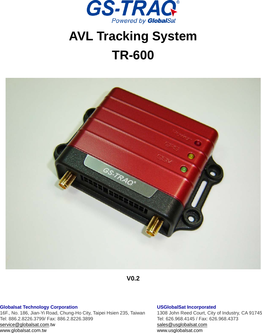
GlobalSat WorldCom TR600 AVL Tracking System User Manual
GlobalSat WorldCom Corporation AVL Tracking System
UserManual.wiki
>
GlobalSat WorldCom
>
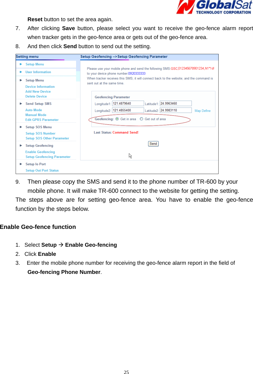
TR600 User Manual
User Manual
Navigation menu
Upload a User Manual
Namespaces
Wiki Guide
HTML
PDF
Info
Views
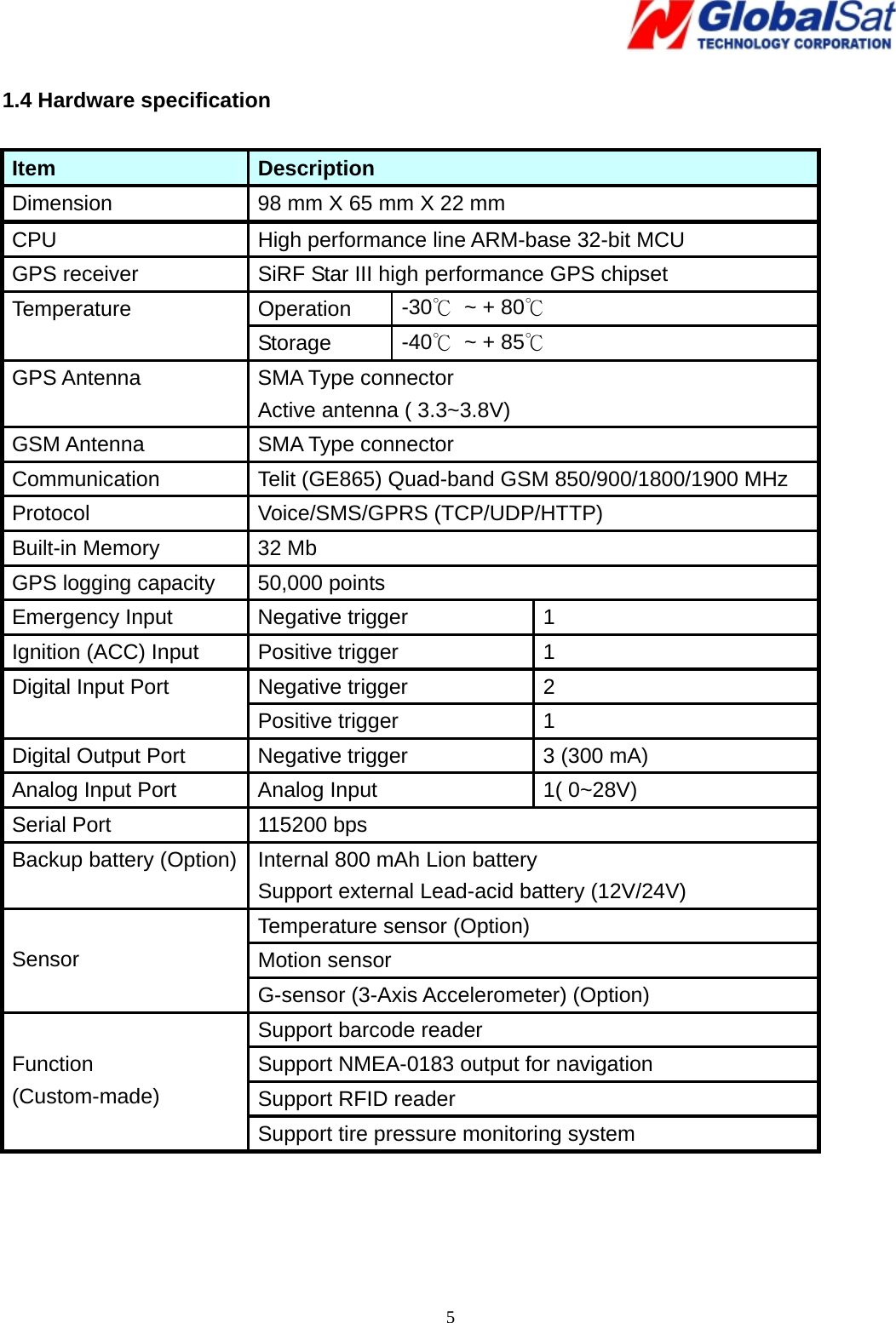
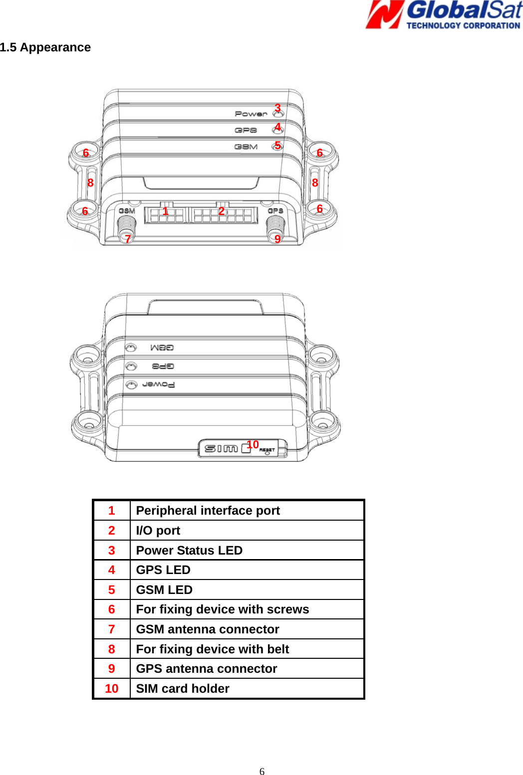
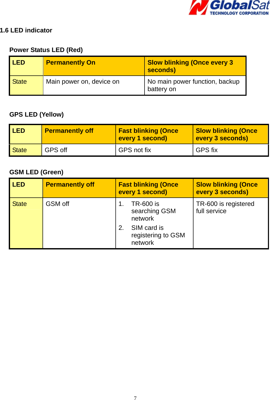
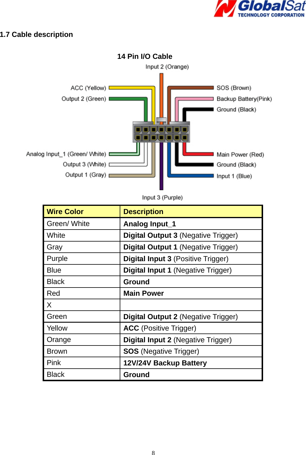
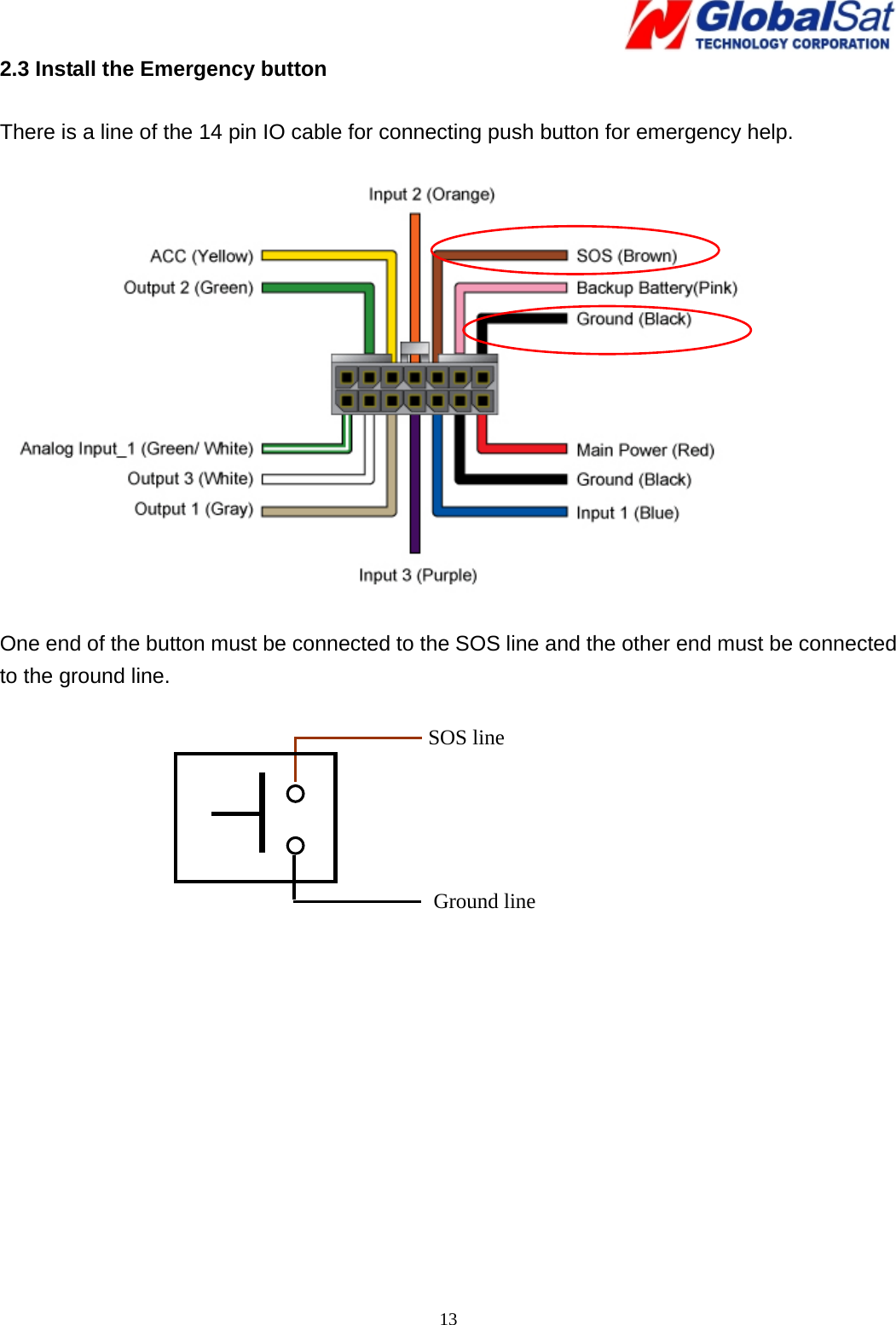
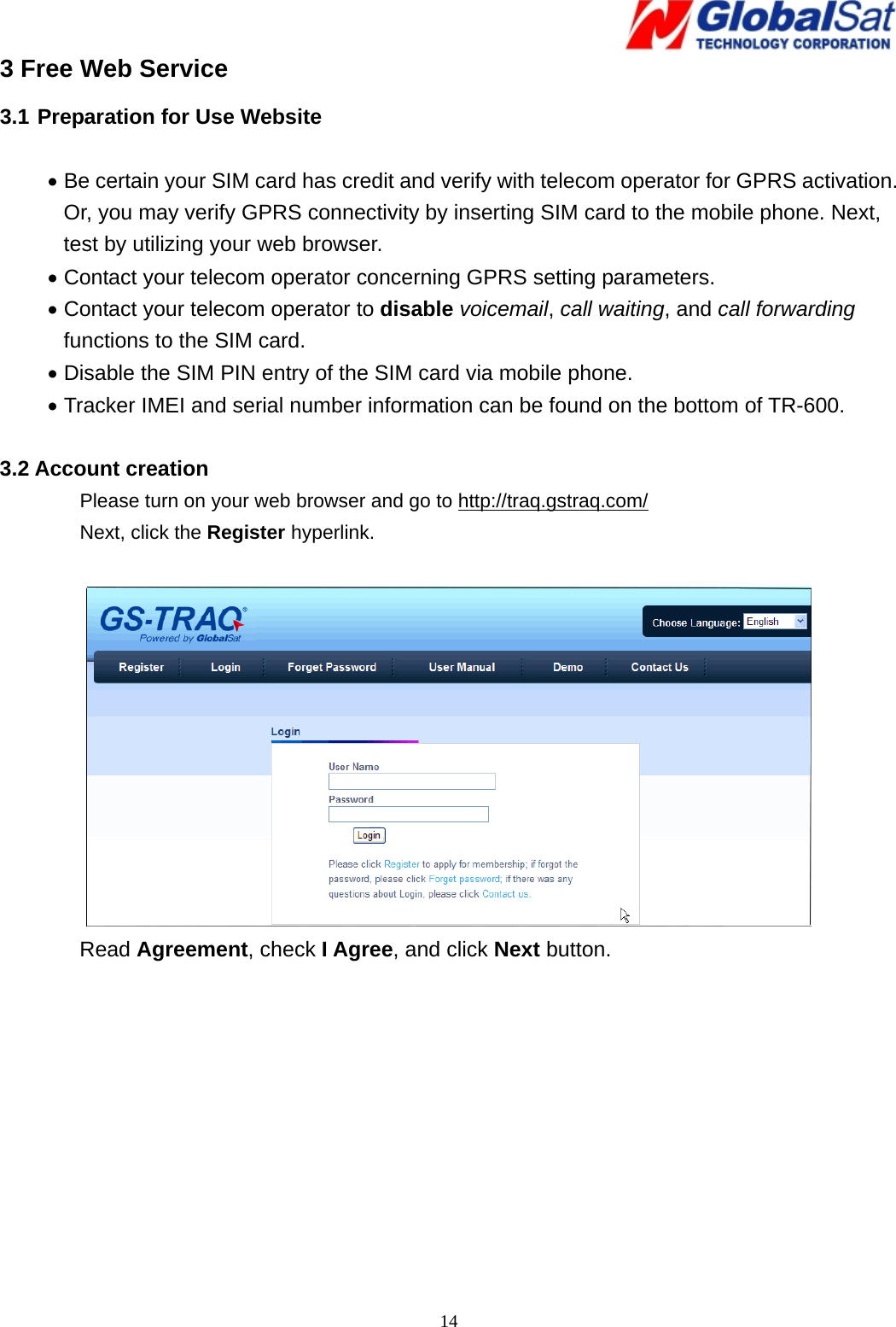
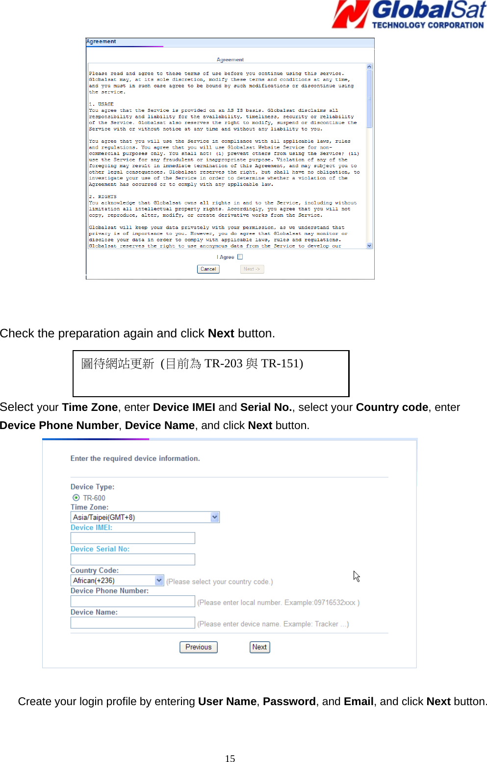
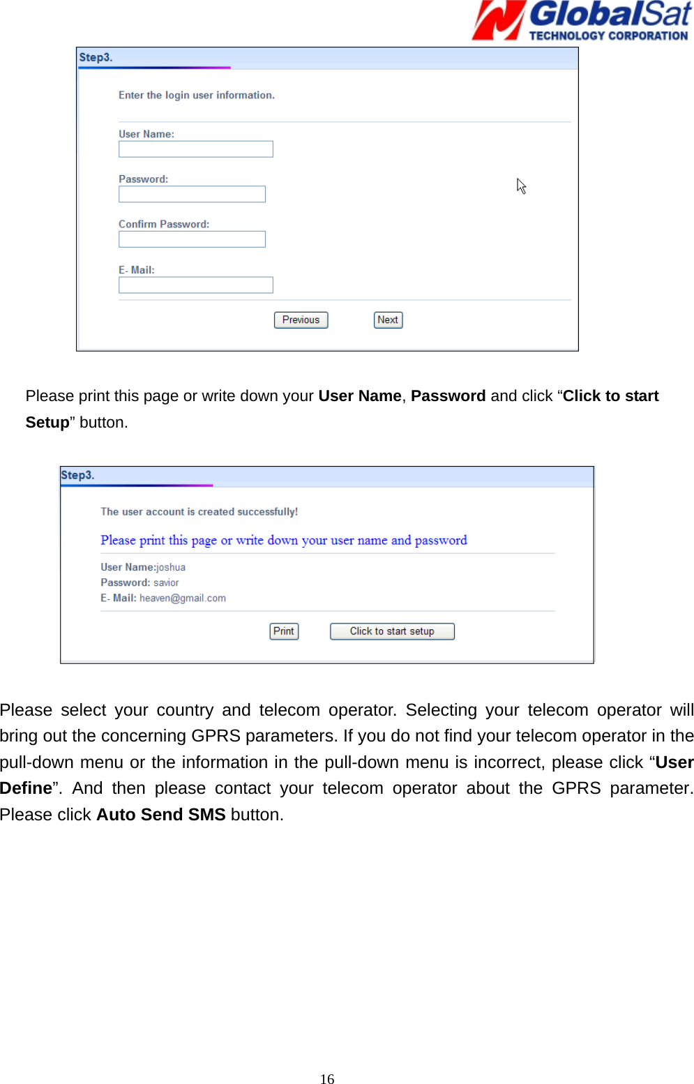
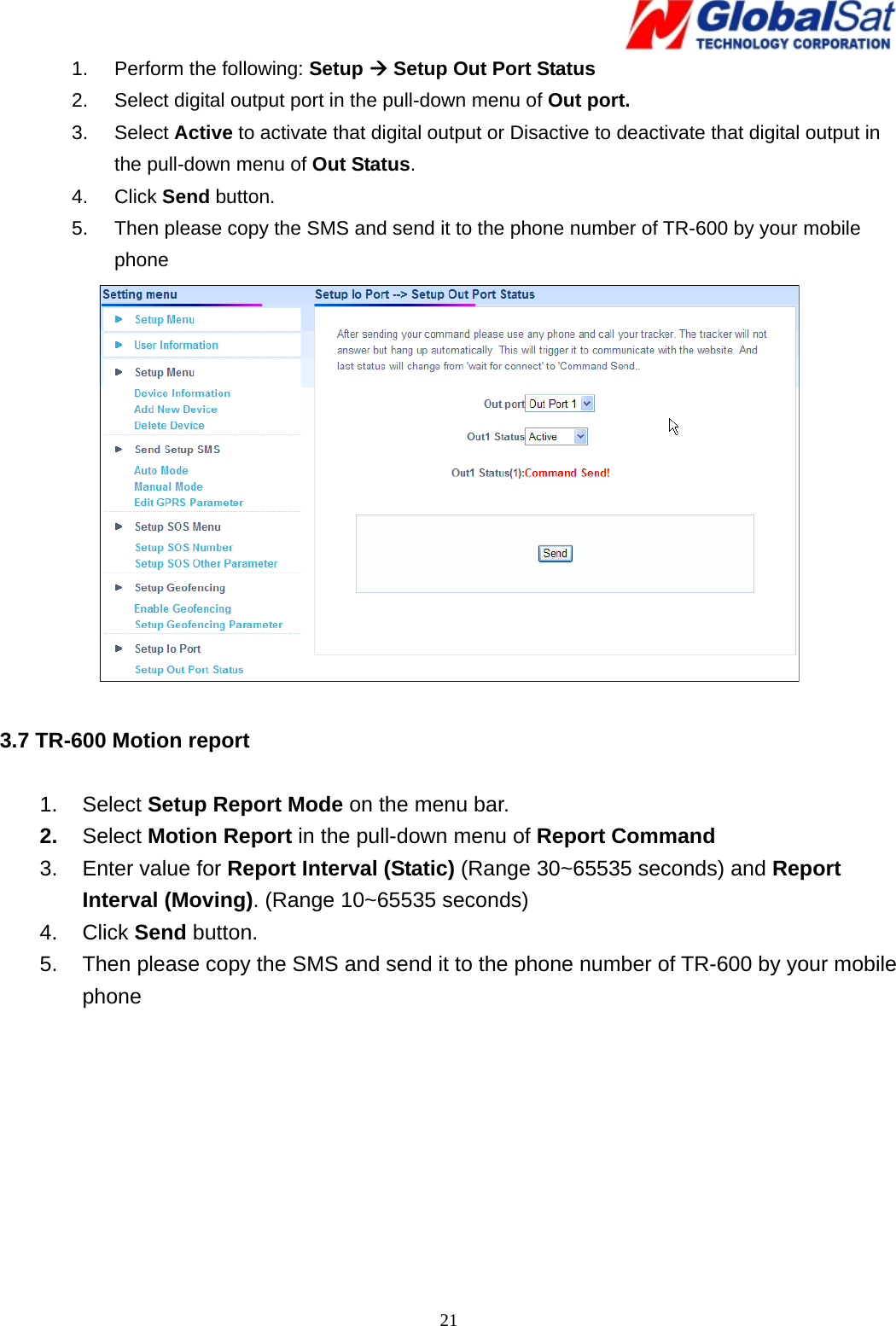
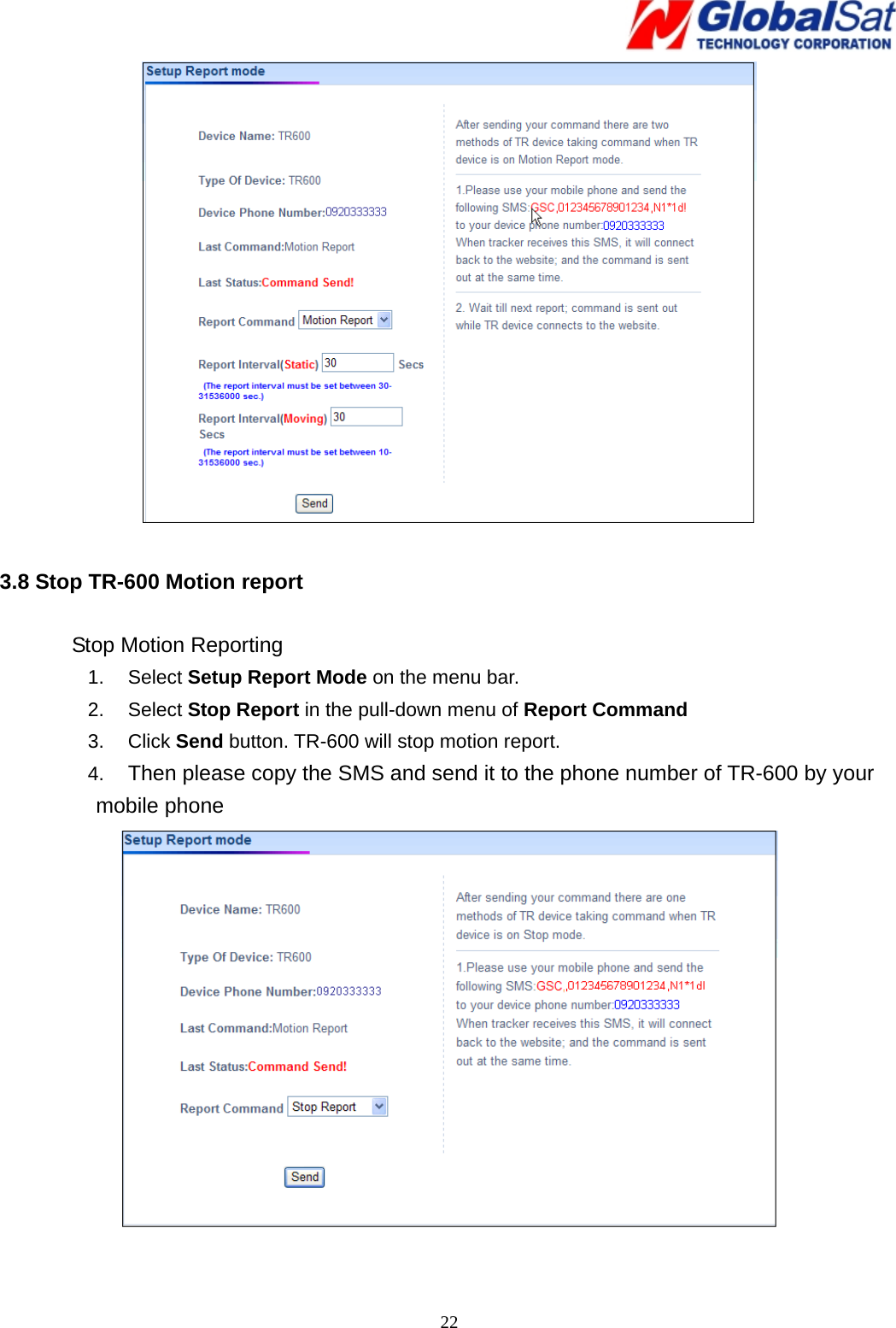
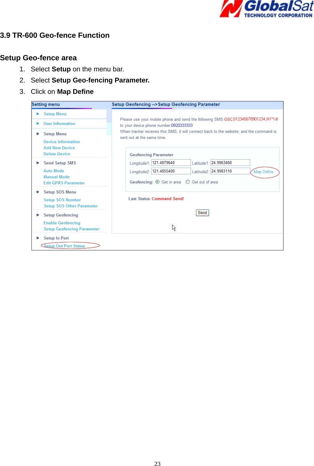
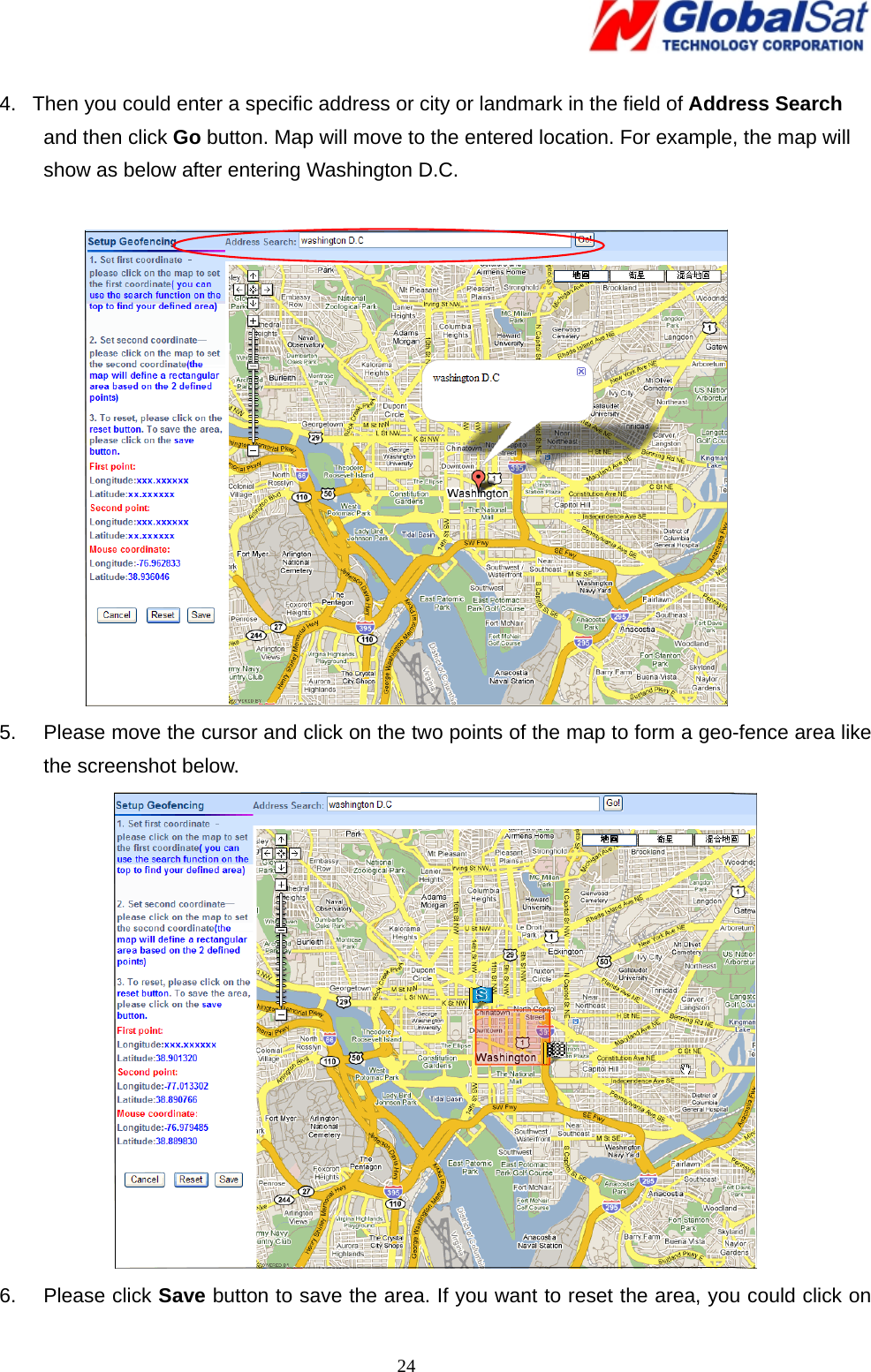
User Manual
Discussion / Help
Navigation