Globalscale Technologies 003-MBX001 MIRABOX User Manual
Globalscale Technologies INC MIRABOX
UserManual.wiki
>
Globalscale Technologies
>
003 MBX001 User Manual
User manual
Navigation menu
Upload a User Manual
Namespaces
Wiki Guide
HTML
PDF
Info
Views
User Manual
Discussion / Help
Navigation
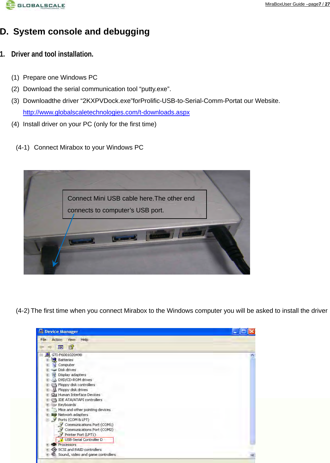
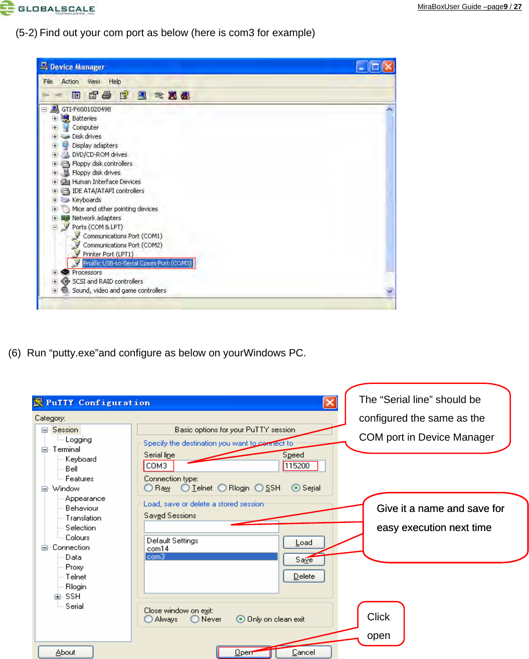
![MiraBoxUser Guide –page8 / 27 (4-3) Run file “2KXPVDock.exe”and the driver will be installed to the PATH C:\cabs\2KXPVDock”. (5) Find out the com port of your debugger on your windows PC. (5-1) Right click [My Computer] [Properties] [Hardware] [Device Manager] Click“Next”tocompletet](https://usermanual.wiki/Globalscale-Technologies/003-MBX001/User-Guide-1922614-Page-8.png)
![MiraBoxUser Guide –page23 / 27 structi2c_rdwr_ioctl_datae2prom_data;fd=open("/dev/i2c‐0",O_RDWR);/*/dev/i2c‐0isregisteredtothesystem*/if(fd<0){perror("openerror");}e2prom_data.nmsgs=2;e2prom_data.msgs=(structi2c_msg*)malloc(e2prom_data.nmsgs*sizeof(structi2c_msg));if(!e2prom_data.msgs){perror("mallocerror");exit(1);}ioctl(fd,I2C_TIMEOUT,1);/*timeout*/ioctl(fd,I2C_RETRIES,2);/*retriestimes*//***writedatatoe2prom**/e2prom_data.nmsgs=1;(e2prom_data.msgs[0]).len=2;(e2prom_data.msgs[0]).addr=0x25;//e2promdeviceaddress(e2prom_data.msgs[0]).flags=0;//write(e2prom_data.msgs[0]).buf=(unsignedchar*)malloc(2);/***********controltheGPIOOP‐0**************************************/(e2prom_data.msgs[0]).buf[0]=0x18;//e2promwriteaddress(e2prom_data.msgs[0]).buf[1]=0x0;//thedatatowriteret=ioctl(fd,I2C_RDWR,(unsignedlong)&e2prom_data);if(ret<0){perror("ioctlerror2");}/***********controltheGPIOOP‐1**************************************/(e2prom_data.msgs[0]).buf[0]=0x19;//e2promwriteaddress(e2prom_data.msgs[0]).buf[1]=0x0;//thedatatowriteret=ioctl(fd,I2C_RDWR,(unsignedlong)&e2prom_data);if(ret<0){perror("ioctlerror2");}](https://usermanual.wiki/Globalscale-Technologies/003-MBX001/User-Guide-1922614-Page-23.png)
![MiraBoxUser Guide –page24 / 27 /***********controltheGPIOOP‐2**************************************///turnonLED(e2prom_data.msgs[0]).buf[0]=0x1a;//e2promwriteaddress(e2prom_data.msgs[0]).buf[1]=0x0;//thedatatowriteret=ioctl(fd,I2C_RDWR,(unsignedlong)&e2prom_data);if(ret<0){perror("ioctlerror3");}//turnoffLEDsleep(1);//delay1second(e2prom_data.msgs[0]).buf[0]=0x1a;//e2promwriteaddress(e2prom_data.msgs[0]).buf[1]=0xFF;//thedatatowriteret=ioctl(fd,I2C_RDWR,(unsignedlong)&e2prom_data);if(ret<0){perror("ioctlerror3");}/***********controltheGPIOOP‐3**************************************///turnonLEDsleep(1);(e2prom_data.msgs[0]).buf[0]=0x1b;//e2promwriteaddress(e2prom_data.msgs[0]).buf[1]=0x0;//thedatatowriteret=ioctl(fd,I2C_RDWR,(unsignedlong)&e2prom_data);if(ret<0){perror("ioctlerror4");}//turnoffLEDsleep(1);(e2prom_data.msgs[0]).buf[0]=0x1b;//e2promwriteaddress(e2prom_data.msgs[0]).buf[1]=0xFF;//thedatatowriteret=ioctl(fd,I2C_RDWR,(unsignedlong)&e2prom_data);if(ret<0){perror("ioctlerror4");}](https://usermanual.wiki/Globalscale-Technologies/003-MBX001/User-Guide-1922614-Page-24.png)
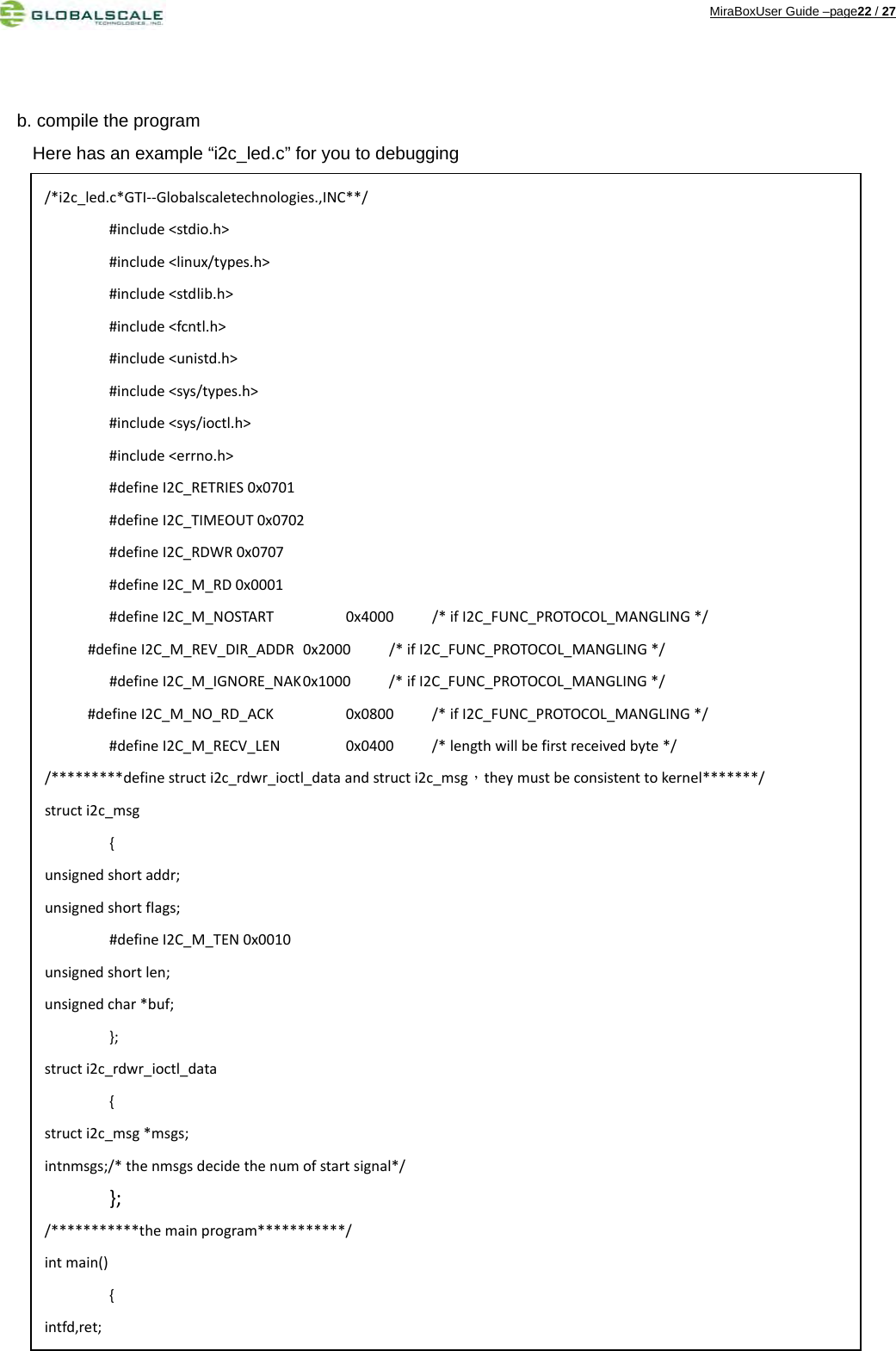
![MiraBoxUser Guide –page25 / 27 Copy this program to file “i2c_led.c” and save to “/home” directory or other else, and compile it use cross-compile tool just have been installed. #cd /home #arm-marvell-linux-gnueabi-gcc -o led i2c_led.c Then copy the executable file “led” to Mirabox and run it. You can see the LED is controlled by youself. /***********controltheGPIOOP‐4**************************************///turnonLEDsleep(1);(e2prom_data.msgs[0]).buf[0]=0x1c;//e2promwriteaddress(e2prom_data.msgs[0]).buf[1]=0x0;//thedatatowriteret=ioctl(fd,I2C_RDWR,(unsignedlong)&e2prom_data);if(ret<0){perror("ioctlerror5");}//turnoffLEDsleep(1);(e2prom_data.msgs[0]).buf[0]=0x1c;//e2promwriteaddress(e2prom_data.msgs[0]).buf[1]=0xFF;//thedatatowriteret=ioctl(fd,I2C_RDWR,(unsignedlong)&e2prom_data);if(ret<0){perror("ioctlerror5");}printf("testingok\n");close(fd);return0;}](https://usermanual.wiki/Globalscale-Technologies/003-MBX001/User-Guide-1922614-Page-25.png)