Globalscale Technologies 003-MBX001 MIRABOX User Manual
Globalscale Technologies INC MIRABOX
User manual

MiraBoxUser Guide –page1 / 27
MiraBox User Guide
Contents
A. Package contents.............................................................................................................................................. 2
B. MiraBox appearance and connecting ports................................................................................................... 4
C. LED indication.................................................................................................................................................... 6
D. System console and debugging ...................................................................................................................... 7
1. Driver and tool installation..................................................................................................................................... 7
2. Go into debugging console. ................................................................................................................................10
3. WiFi AP mode testing......................................................................................................................................... 11
4. WIFI Client mode testing .................................................................................................................................... 13
5. Gigabit ethernet ports......................................................................................................................................... 16
6. USB 3.0 port ..................................................................................................................................................... 17
7. Multi-IO port ...................................................................................................................................................... 18
8. Reset................................................................................................................................................................ 26
9. Download sites.................................................................................................................................................. 27
10. FCC STATEMENT......................................................................................................................................... 27
11. RF warning statement: ................................................................................................................................... 27
-Sep18, 2012
MiraBoxUser Guide –page2 / 27
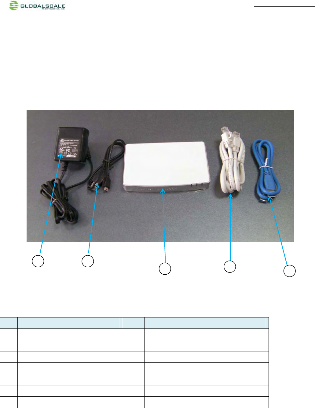
A. Package contents
1. Standard package contents
MiraBoxstandard content List Remark
1 MiraBox 1 unit Mirabox main unit
2 AC-DC Power Adapter 1 pc Input 90-240VAC / output 5V,3A DC
3 Ethernet Cable 1 pc Cat 5e
4 USB3.0 Cable 1 pc
5 Mini-USB Cable 1 pc For debug console use
6 Quick reference card 1 pc
7 Warranty card 1 pc
1
2
4
53
MiraBoxUser Guide –page3 / 27
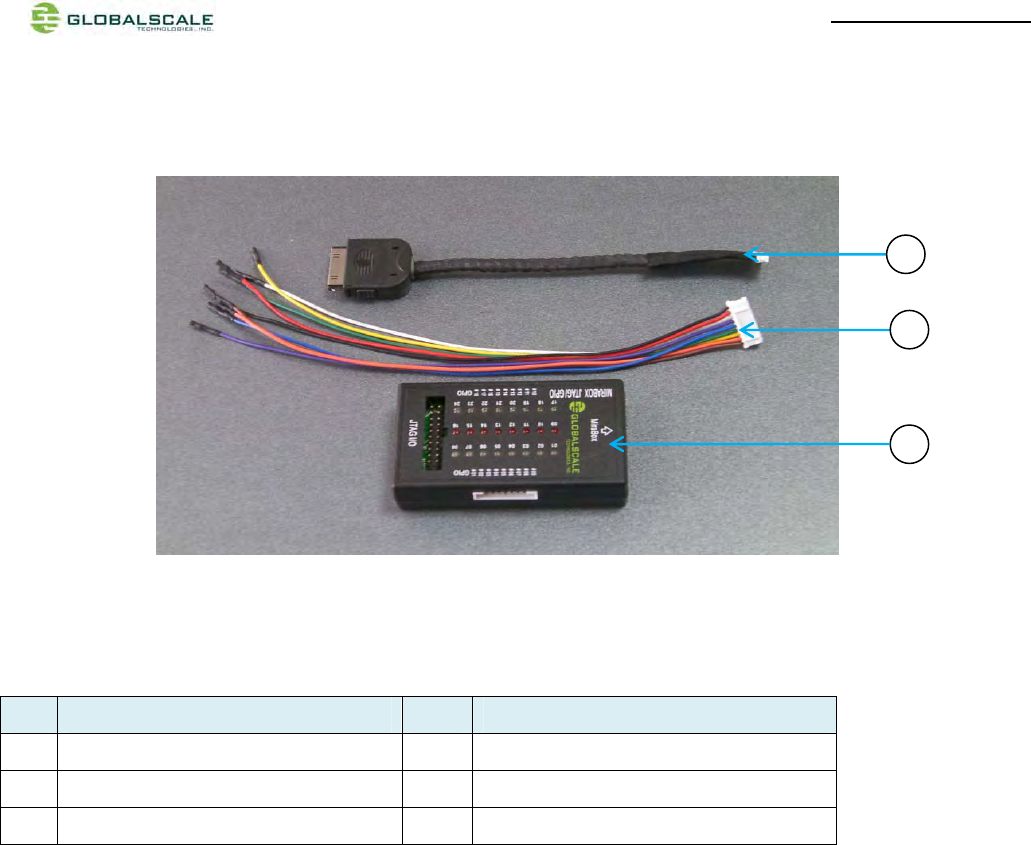
2. Optional package contents
MiraBoxOptional Content List
6 Multi I/O Cable 1 pc Connect from MiraBox to JTAG/GPIO box
7 GPIO Cable 1 pc For GPIO port connection
8 MiraBox JTAG/GPIO box 1 pc External JTAG/GPIO box for debugging
8
6
7
MiraBoxUser Guide –page4 / 27
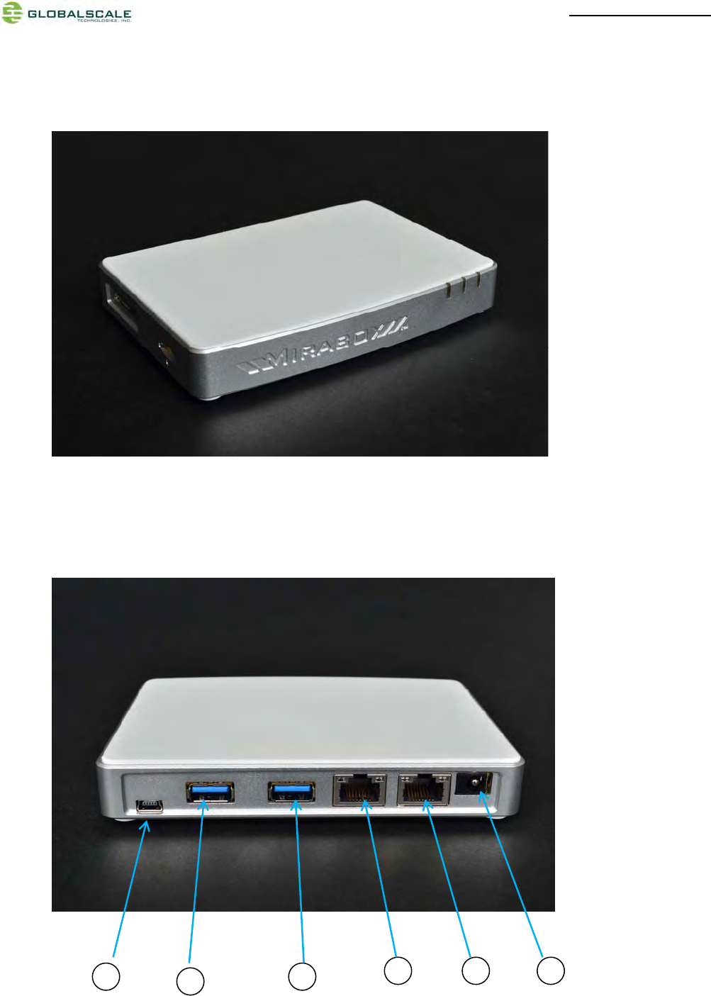
B. MiraBox appearance and connecting ports
123
64
5
MiraBoxUser Guide –page5 / 27
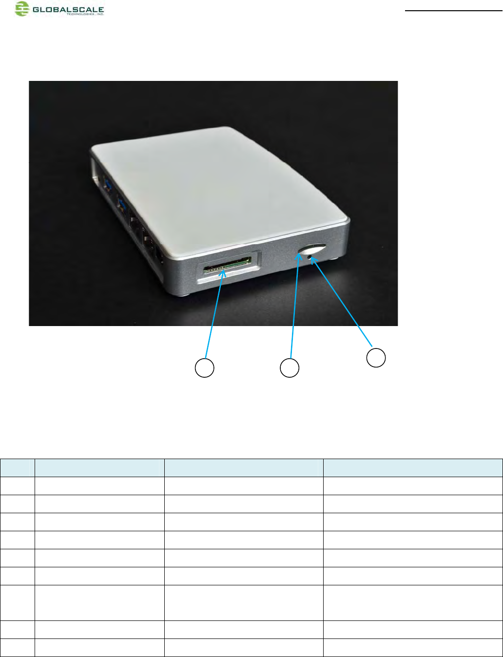
Mirabox ports description
Connection port Description Remark
1 Power Port DC 5V/3A port
2 RJ45 #1 Gigabit Ethernet port1
3 RJ45 #2 Gigabit Ethernet port2
4 USB 3.0 port#1 USB 3.0 high speed host
5 USB 3.0 port#2 USB 3.0 high speed host
6 Mini USB console port Debug console Connect to PC USB port
7 Multi-I/O port JTAG and GPIO port Connect to external JTAG/GPIO box for system
development.
8 Micro SD slot External Micro-SD slot
9 Reset button hole System reset button Reset through GPIO
9
87
MiraBoxUser Guide –page6 / 27
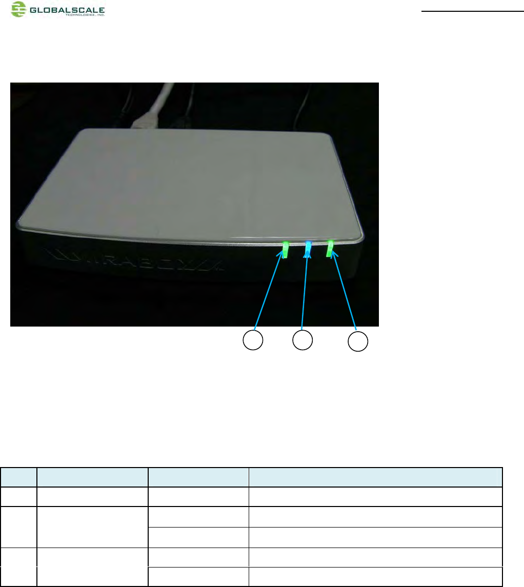
C. LED indication
LED indication table
LED Color/ Pattern Description
1 Power on LED Solid green Upon power on, this LED lights up
Blinking blue Indicate WiFi AP mode is activated as default after boot up 2 WiFi AP
Off WiFi AP mode is not activated
Blinking green WiFi client mode is activated
3 WiFi client Off WiFi client mode is not activated
31
2
MiraBoxUser Guide –page7 / 27
D. System console and debugging
1. Driver and tool installation.
(1) Prepare one Windows PC
(2) Download the serial communication tool “putty.exe”.
(3) Downloadthe driver “2KXPVDock.exe”forProlific-USB-to-Serial-Comm-Portat our Website.
http://www.globalscaletechnologies.com/t-downloads.aspx
(4) Install driver on your PC (only for the first time)
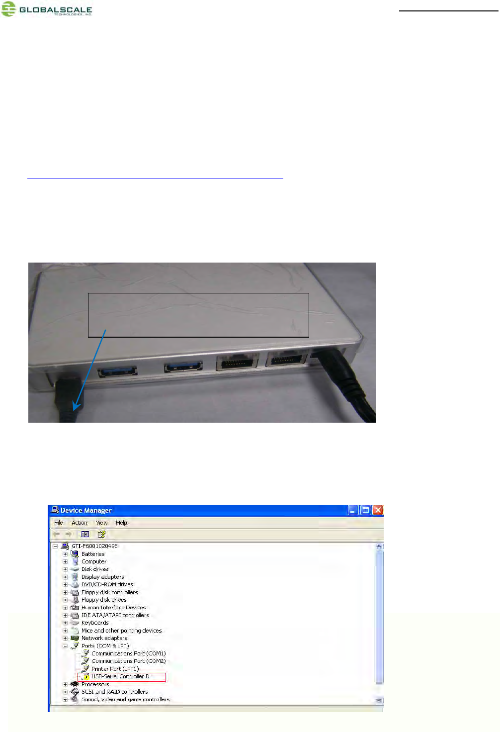
(4-1) Connect Mirabox to your Windows PC
(4-2) The first time when you connect Mirabox to the Windows computer you will be asked to install the driver
Connect Mini USB cable here.The other end
connects to computer’s USB port.
MiraBoxUser Guide –page8 / 27
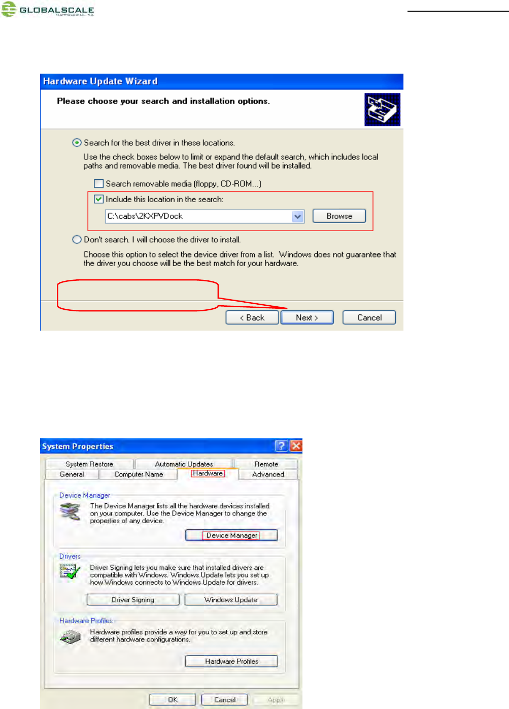
(4-3) Run file “2KXPVDock.exe”and the driver will be installed to the PATH C:\cabs\2KXPVDock”.
(5) Find out the com port of your debugger on your windows PC.
(5-1) Right click [My Computer] [Properties] [Hardware] [Device Manager]
Click“Next”tocompletet
MiraBoxUser Guide –page9 / 27
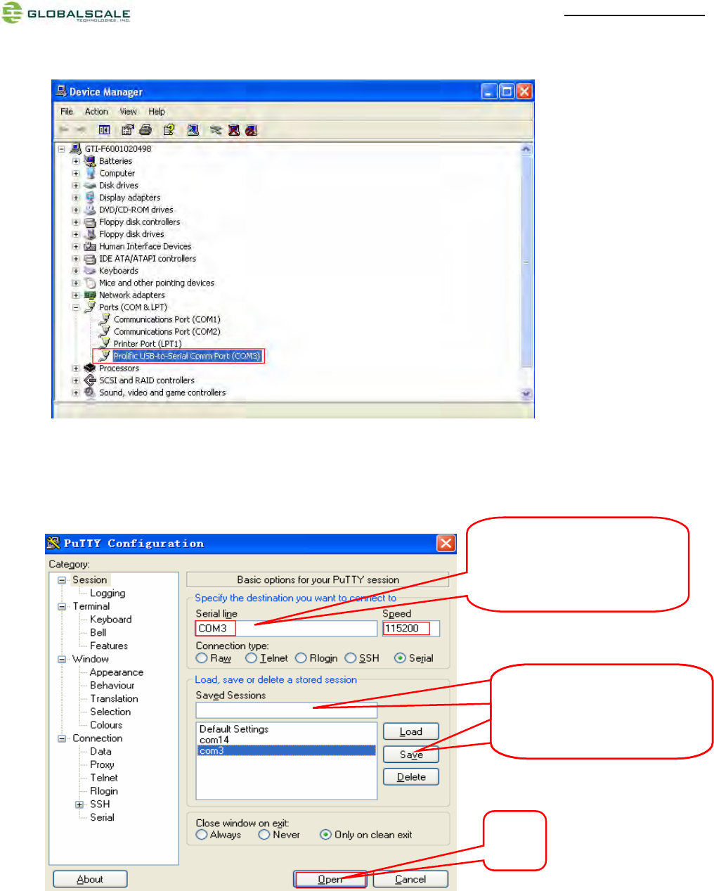
(5-2) Find out your com port as below (here is com3 for example)
(6) Run “putty.exe”and configure as below on yourWindows PC.
The “Serial line” should be
configured the same as the
COM port in Device Manager
Give it a name and save for
easy execution next time
Give it a name and save for
easy execution next time
Click
o
p
en
MiraBoxUser Guide –page10 / 27
2. Go into debugging console.
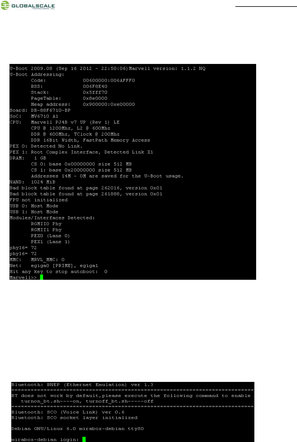
(1) Power on the MiraBoxand you will see messages on screen as below
(2) You can press any key to stop auto-boot when you see the bootdelay timer is counting down.
After entering the uboot prompt, you can also change the uboot environment variables such
asbootdelaytime, Ipaddr,serverip and so on.
(3) If no key was pressed to interrupt the uboot, it will continue running to the login screen where urges you to
input the login name and password, here is the default login information.
Login :root
Password: nosoup4u
MiraBoxUser Guide –page11 / 27
(4) Now you are the root user and have the full control of the mirabox
3. WiFi AP mode testing
MiraBoxServer has a built-in WiFi module which is in compliance with 802.11 b/g/n standard. The WiFican work
as client or AP modebut only one at a time. The default mode is AP modeevery time when it powers on, and the
indication light D6 is blinking blue.
Here are steps for testing:
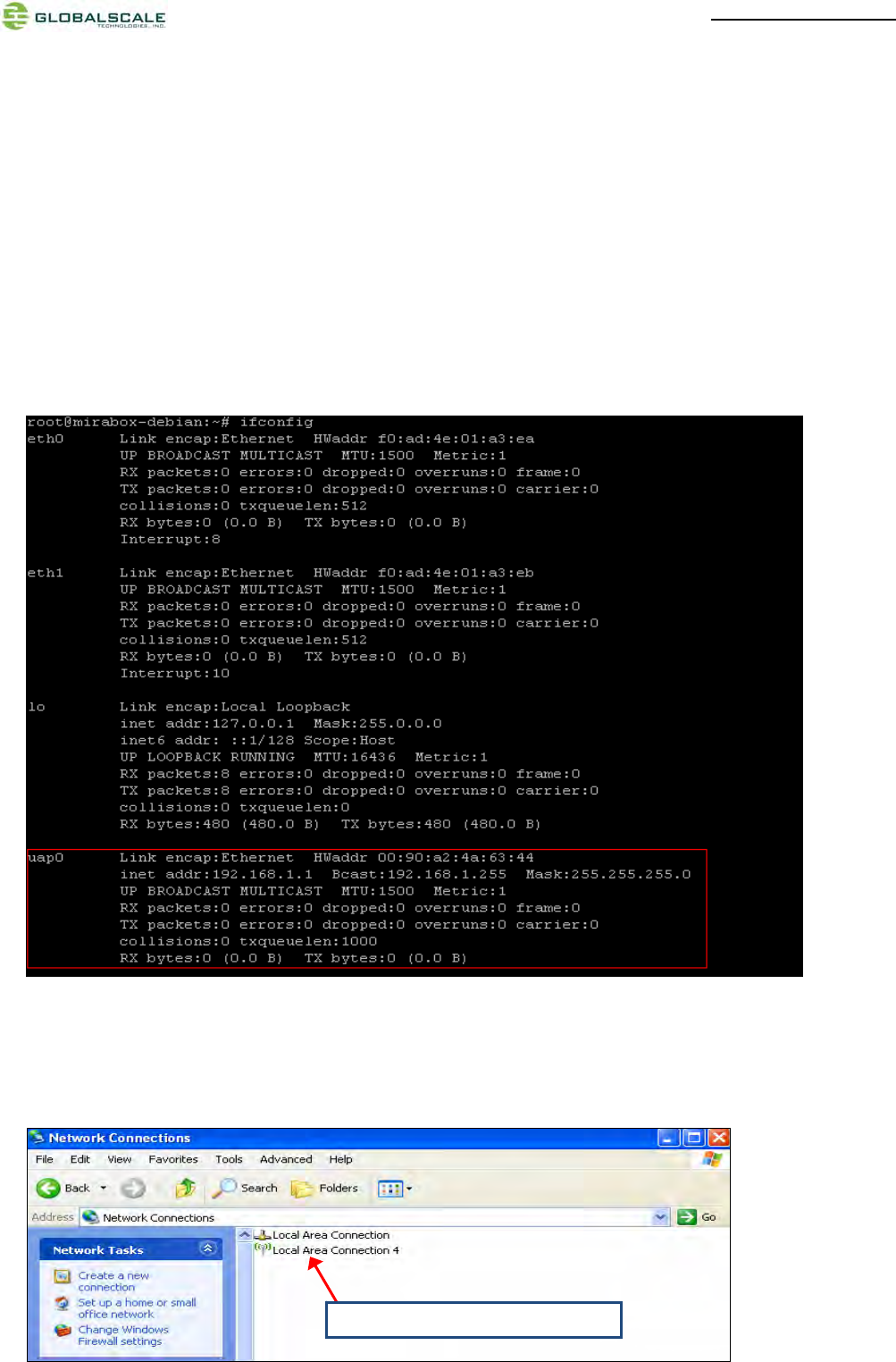
(1) Enter command and you will see message for uap0 device.
#ifconfig
(2) Prepare one computer installed with Wi-Fi Lan card, here we use computer with Windows XP operating system
for example.
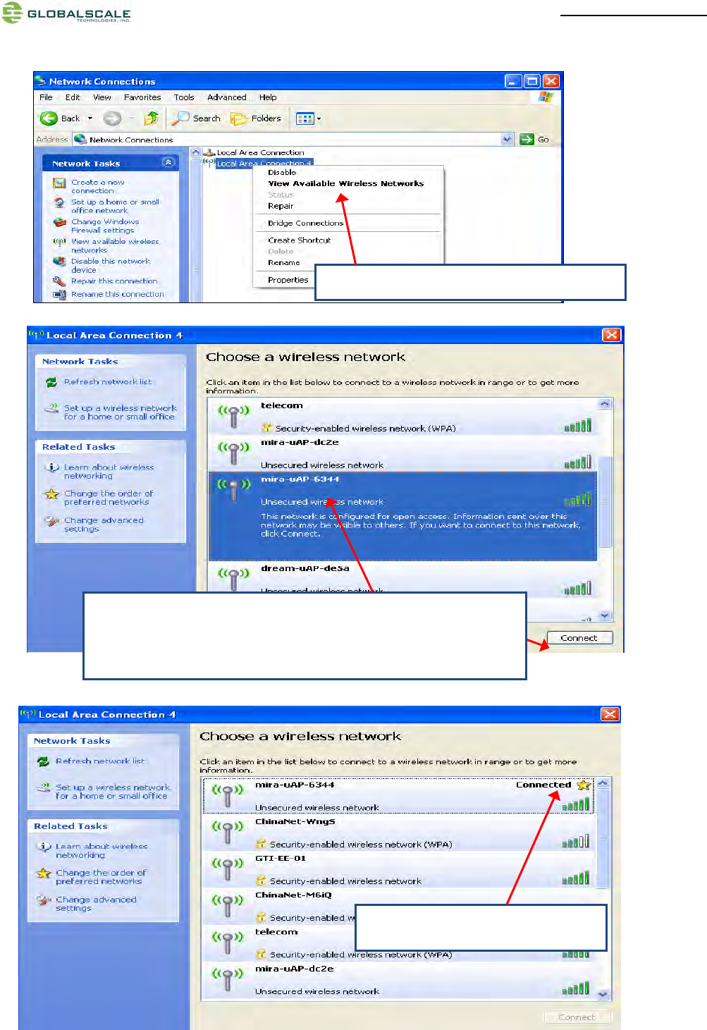
(3) Go to “Network Connections”as shown below..
1. Select “Local Area connection 4”
MiraBoxUser Guide –page12 / 27
3. Choose name with “mira-uAP-6344”, here digits”6344” is the last
four digits of MAC address for the MiraBoxWiFi
Then click “Connect”.
4. Successfully connected.
2. Select “View Available Wireless Networks”
MiraBoxUser Guide –page13 / 27
4. WIFI Client mode testing
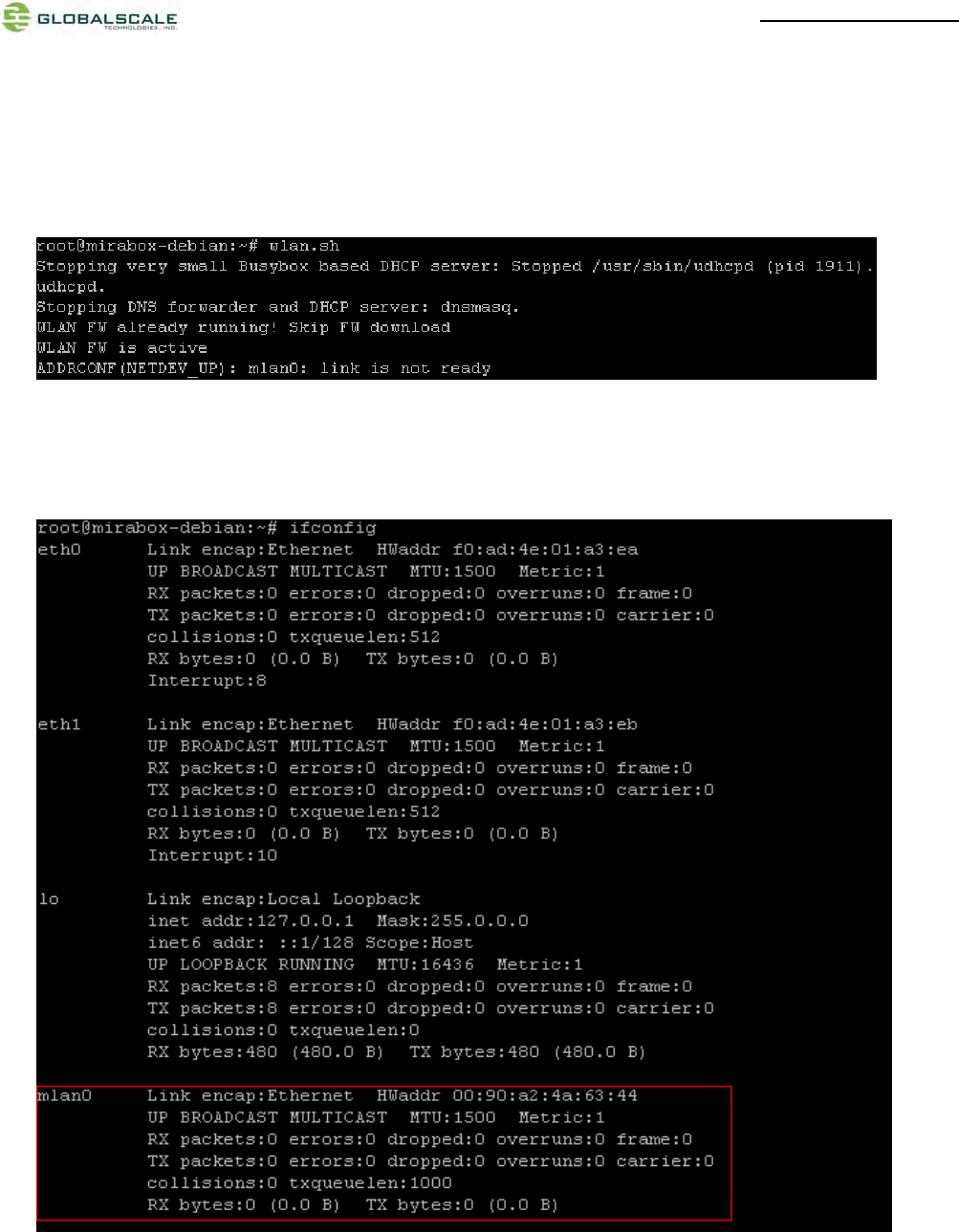
(1) Switchto WiFiclient mode by giving command as following.
# wlan.sh
When done successfully, the LED(D7) is blinking green and mlan0 is activated.
(2) To check mlan0 with ifconfig command
# ifconfig
MiraBoxUser Guide –page14 / 27
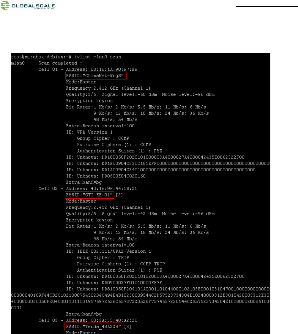
(3) Scan for WiFi AP near-by
# iwlist mlan0 scan
MiraBoxUser Guide –page15 / 27
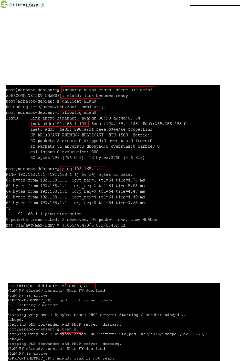
(4) Connect to WiFi AP
# iwconfig mlan0 essid<AP’s ID>
# dhclient mlan0
# ifconfig mlan0
#ping 192.168.1.1
The below screenshot is a example for how to connect a mlan device. If you can see IP address (for example:
192.168.1.102) means you have already connected and got an IP.
(5) Switch back to WiFi AP mode
There are two useful script files:
Client_ap.sh – switch from wifi client mode to wifi AP mode
Wlan.sh – switch from wifi AP mode to wifi client mode
MiraBoxUser Guide –page16 / 27
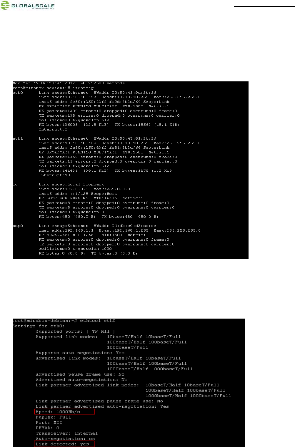
5. Gigabit ethernet ports
(1) Connect the two Gigabit Ethernet ports to Gigabit switch by Network cables. Normally it will get an IP address
assigned by DHCP.
Enter command as below to check:
#ifconfig
(2) Testing the speed of Gigabit Ethernet ports
#ethtool eth0
Normally you will see the information as below:
MiraBoxUser Guide –page17 / 27
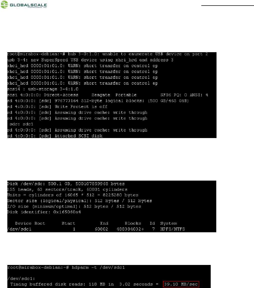
6. USB 3.0 port
(1) Plug in the usb3.0 hard disk or flash disk to the USB port then you can see some driver messages as below
of this device
(2) View the usb3.0 hard disk
#fdisk-l
you will see below messages of the usb3.0 devicewhich is usually shown as /dev/sdb*、/dev/sdc*.
(3) Testing the access speed of the usb3.0 ports
#hdparm-t /dev/sdc1
MiraBoxUser Guide –page18 / 27
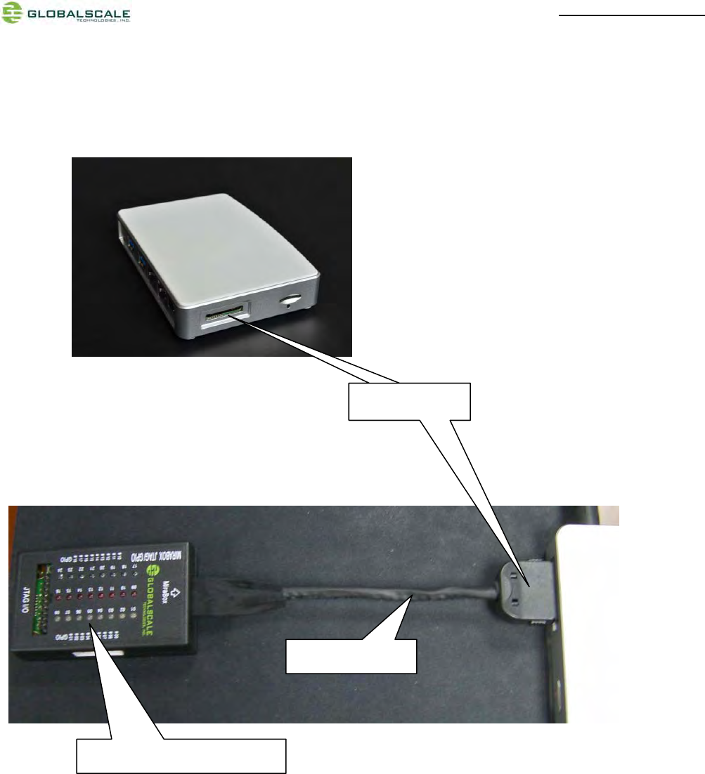
7. Multi-IO port
Connect the MIRABOX JTAG/GPIO box to the Multi-IO port via Multi-IO cable.
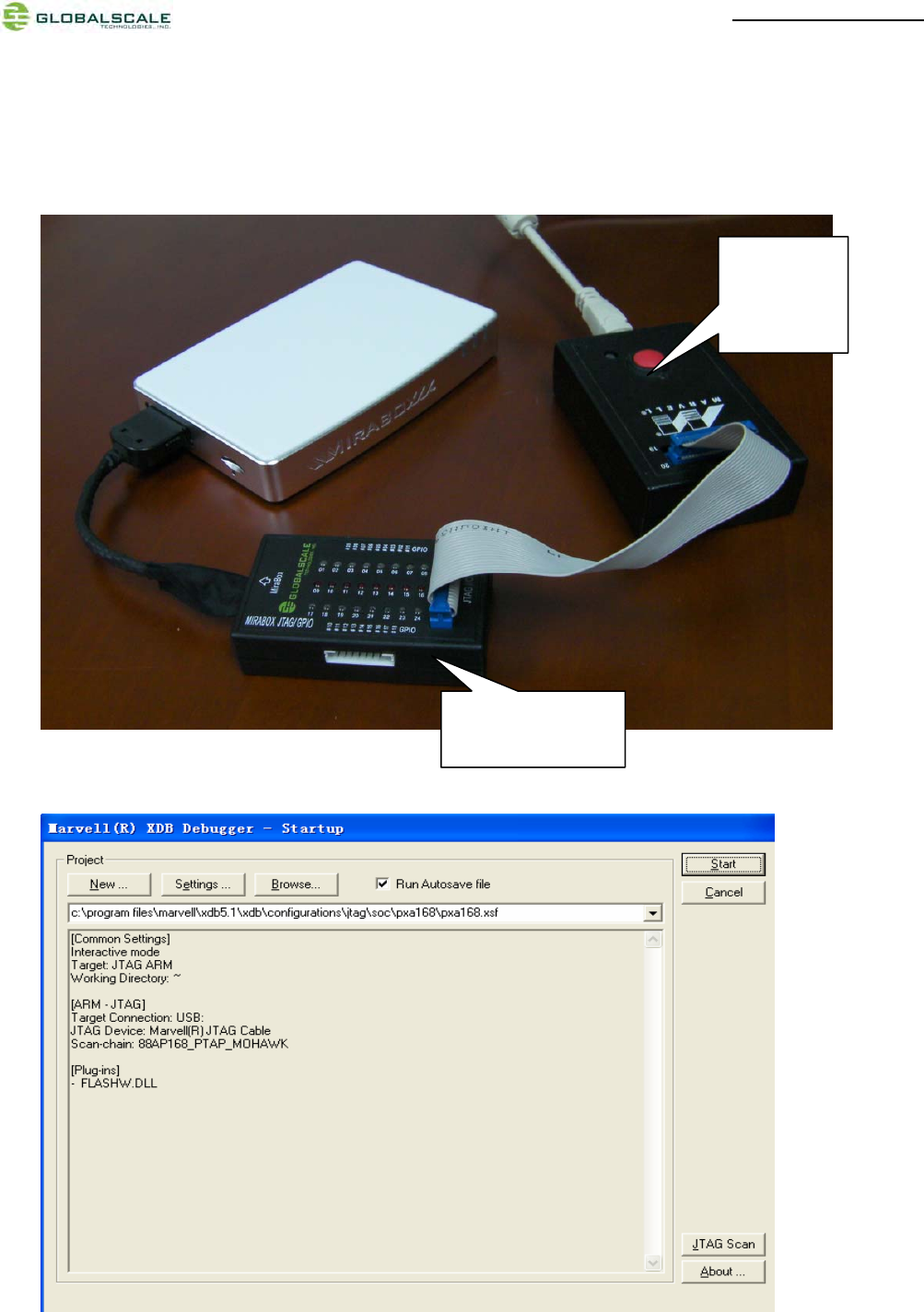
(1) JTAGinterface
Pleaseconnectthedebuggertothe20‐pinJTAGslotasshownbelow,hereweusetheMarvell
BlackStonedebuggerandXDB(MarvelleXtremeDebugger5.1)softwareonWindowsPCfor
example.
MiraBoxJTAG/GPIObox
Multi‐I/OCable
Multi‐I/Oport
Multi‐I/Oport
MiraBoxUser Guide –page19 / 27
Debuggerconnection
RunXDBonWindowsPC
MiraBoxJTAG
GPIO
Marvell
BlackStone
debugger
MiraBoxUser Guide –page20 / 27
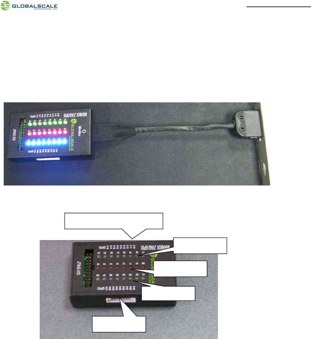
(2) GPIOinterfaceandcontrol
(2-1) There is a demo program to show the GPIO LEDs by entering command as below:
#ledtest1
This will light up the LEDs for 3 seconds then light off.
(2-2)Control the LED by yourself
\
GPIOport1
GPIO
p
ort2
GPIOport3
GPIOport4
TheothersideisGPIOport0
MiraBoxUser Guide –page21 / 27
a. preparation
1. Prepare a host pc with linux (as:fedora 14) installed, and download the cross tool chain
“arm-marvell-linux-gnueabi-vfp.tar.bz2” from our
websitehttp://www.plugcomputer.org/downloads/d2plug/or
http://www.globalscaletechnologies.comor
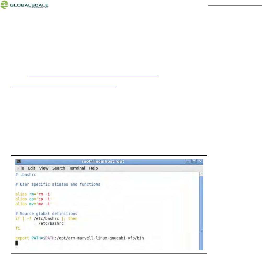
2. Install and configure the tool chain
Copy “arm-marvell-linux-gnueabi-vfp.tar.bz2” to directory /opt
#cd /opt
#tar -jxfarm-marvell-linux-gnueabi-vfp.tar.bz2
#ls
#vim /root/.bashrc
Add “export PATH=$PATH:/opt/arm-marvell-linux-gnueabi-vfp/bin” to last line as below, then save and exit.
Enable the PATH
#source /root/.bash_profile

MiraBoxUser Guide –page22 / 27
b. compile the program
Here has an example “i2c_led.c” for you to debugging
/*i2c_led.c*GTI‐‐Globalscaletechnologies.,INC**/
#include<stdio.h>
#include<linux/types.h>
#include<stdlib.h>
#include<fcntl.h>
#include<unistd.h>
#include<sys/types.h>
#include<sys/ioctl.h>
#include<errno.h>
#defineI2C_RETRIES0x0701
#defineI2C_TIMEOUT0x0702
#defineI2C_RDWR0x0707
#defineI2C_M_RD0x0001
#defineI2C_M_NOSTART 0x4000/*ifI2C_FUNC_PROTOCOL_MANGLING*/
#defineI2C_M_REV_DIR_ADDR0x2000/*ifI2C_FUNC_PROTOCOL_MANGLING*/
#defineI2C_M_IGNORE_NAK0x1000/*ifI2C_FUNC_PROTOCOL_MANGLING*/
#defineI2C_M_NO_RD_ACK 0x0800/*ifI2C_FUNC_PROTOCOL_MANGLING*/
#defineI2C_M_RECV_LEN 0x0400/*lengthwillbefirstreceivedbyte*/
/*********definestructi2c_rdwr_ioctl_dataandstructi2c_msg,theymustbeconsistenttokernel*******/
structi2c_msg
{
unsignedshortaddr;
unsignedshortflags;
#defineI2C_M_TEN0x0010
unsignedshortlen;
unsignedchar*buf;
};
structi2c_rdwr_ioctl_data
{
structi2c_msg*msgs;
intnmsgs;/*thenmsgsdecidethenumofstartsignal*/
};
/***********themainprogram***********/
intmain()
{
intfd,ret;

MiraBoxUser Guide –page23 / 27
structi2c_rdwr_ioctl_datae2prom_data;
fd=open("/dev/i2c‐0",O_RDWR);/*/dev/i2c‐0isregisteredtothesystem*/
if(fd<0)
{
perror("openerror");
}
e2prom_data.nmsgs=2;
e2prom_data.msgs=(structi2c_msg*)malloc(e2prom_data.nmsgs*sizeof(structi2c_msg));
if(!e2prom_data.msgs)
{
perror("mallocerror");
exit(1);
}
ioctl(fd,I2C_TIMEOUT,1);/*timeout*/
ioctl(fd,I2C_RETRIES,2);/*retriestimes*/
/***writedatatoe2prom**/
e2prom_data.nmsgs=1;
(e2prom_data.msgs[0]).len=2;
(e2prom_data.msgs[0]).addr=0x25;//e2promdeviceaddress
(e2prom_data.msgs[0]).flags=0;//write
(e2prom_data.msgs[0]).buf=(unsignedchar*)malloc(2);
/***********controltheGPIOOP‐0**************************************/
(e2prom_data.msgs[0]).buf[0]=0x18;//e2promwriteaddress
(e2prom_data.msgs[0]).buf[1]=0x0;//thedatatowrite
ret=ioctl(fd,I2C_RDWR,(unsignedlong)&e2prom_data);
if(ret<0)
{
perror("ioctlerror2");
}
/***********controltheGPIOOP‐1**************************************/
(e2prom_data.msgs[0]).buf[0]=0x19;//e2promwriteaddress
(e2prom_data.msgs[0]).buf[1]=0x0;//thedatatowrite
ret=ioctl(fd,I2C_RDWR,(unsignedlong)&e2prom_data);
if(ret<0)
{
perror("ioctlerror2");
}

MiraBoxUser Guide –page24 / 27
/***********controltheGPIOOP‐2**************************************/
//turnonLED
(e2prom_data.msgs[0]).buf[0]=0x1a;//e2promwriteaddress
(e2prom_data.msgs[0]).buf[1]=0x0;//thedatatowrite
ret=ioctl(fd,I2C_RDWR,(unsignedlong)&e2prom_data);
if(ret<0)
{
perror("ioctlerror3");
}
//turnoffLED
sleep(1);//delay1second
(e2prom_data.msgs[0]).buf[0]=0x1a;//e2promwriteaddress
(e2prom_data.msgs[0]).buf[1]=0xFF;//thedatatowrite
ret=ioctl(fd,I2C_RDWR,(unsignedlong)&e2prom_data);
if(ret<0)
{
perror("ioctlerror3");
}
/***********controltheGPIOOP‐3**************************************/
//turnonLED
sleep(1);
(e2prom_data.msgs[0]).buf[0]=0x1b;//e2promwriteaddress
(e2prom_data.msgs[0]).buf[1]=0x0;//thedatatowrite
ret=ioctl(fd,I2C_RDWR,(unsignedlong)&e2prom_data);
if(ret<0)
{
perror("ioctlerror4");
}
//turnoffLED
sleep(1);
(e2prom_data.msgs[0]).buf[0]=0x1b;//e2promwriteaddress
(e2prom_data.msgs[0]).buf[1]=0xFF;//thedatatowrite
ret=ioctl(fd,I2C_RDWR,(unsignedlong)&e2prom_data);
if(ret<0)
{
perror("ioctlerror4");
}

MiraBoxUser Guide –page25 / 27
Copy this program to file “i2c_led.c” and save to “/home” directory or other else, and compile it use
cross-compile tool just have been installed.
#cd /home
#arm-marvell-linux-gnueabi-gcc -o led i2c_led.c
Then copy the executable file “led” to Mirabox and run it. You can see the LED is controlled by youself.
/***********controltheGPIOOP‐4**************************************/
//turnonLED
sleep(1);
(e2prom_data.msgs[0]).buf[0]=0x1c;//e2promwriteaddress
(e2prom_data.msgs[0]).buf[1]=0x0;//thedatatowrite
ret=ioctl(fd,I2C_RDWR,(unsignedlong)&e2prom_data);
if(ret<0)
{
perror("ioctlerror5");
}
//turnoffLED
sleep(1);
(e2prom_data.msgs[0]).buf[0]=0x1c;//e2promwriteaddress
(e2prom_data.msgs[0]).buf[1]=0xFF;//thedatatowrite
ret=ioctl(fd,I2C_RDWR,(unsignedlong)&e2prom_data);
if(ret<0)
{
perror("ioctlerror5");
}
printf("testingok\n");
close(fd);
return0;
}
MiraBoxUser Guide –page26 / 27
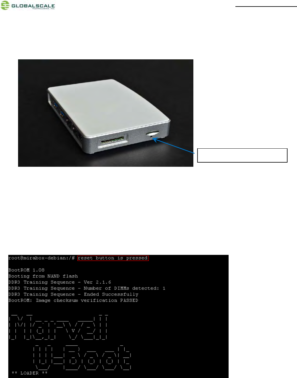
8. Reset
(1) GPIO reset button
The reset button is connected to one GPIO which means controlled by software.
When you press down this button by using a sharp pin, it arouses attention of CPU then CPU asserts the master
reset low signal to start the system reset session.
Below is the reboot screen after reset
Note: Since this reset function is controlled by software so it will not be handled during boot-up session.
(2) More push button functions
System developer can program this button to have more functions by different press-then-release delay time.
6、GPIO reset button hole.

MiraBoxUser Guide –page27 / 27
9. Download sites
To download the files for MiraBox server, please visit:
http://www.globalscaletechnologies.com/t-downloads.aspx
Other useful resource links are:
http://www.plugcomputer.org/
http://plugcomputer.org/plugwiki/index.php/GuruPlug
10. FCC STATEMENT
1. This device complies with Part 15 of the FCC Rules. Operation is subject to the following two conditions:
(1) This device may not cause harmful interference.
(2) This device must accept any interference received, including interference that may cause undesired
operation.
2. Changes or modifications not expressly approved by the party responsible for compliance could void the user's
authority to operate the equipment.
NOTE: This equipment has been tested and found to comply with the limits for a Class B digital device, pursuant to
Part 15 of the FCC Rules. These limits are designed to provide reasonable protection against harmful interference in
a residential installation.
This equipment generates uses and can radiate radio frequency energy and, if not installed and used in accordance
with the instructions, may cause harmful interference to radio communications. However, there is no guarantee that
interference will not occur in a particular installation. If this equipment does cause harmful interference to radio or
television reception, which can be determined by turning the equipment off and on, the user is encouraged to try to
correct the interference by one or more of the following measures:
--- Reorient or relocate the receiving antenna.
--- Increase the separation between the equipment and receiver.
--- Connect the equipment into an outlet on a circuit different from that to which the receiver is connected.
--- Consult the dealer or an experienced radio/TV technician for help.
11. RF warning statement:
ThisequipmentcomplieswithFCCradiationexposurelimitssetforthforanuncontrolled
environment.Thisequipmentshouldbeinstalledandoperatedwithminimumdistance20cm
betweentheradiator&yourbody