Gogo Business Aviation SIPWFHS WiFi SIP Handset User Manual FCC labelx
Gogo Business Aviation LLC WiFi SIP Handset FCC labelx
UserManual.wiki
>
Gogo Business Aviation
>
SIPWFHS User Manual
Users Manual
Navigation menu
Upload a User Manual
Namespaces
Wiki Guide
HTML
PDF
Info
Views
User Manual
Discussion / Help
Navigation
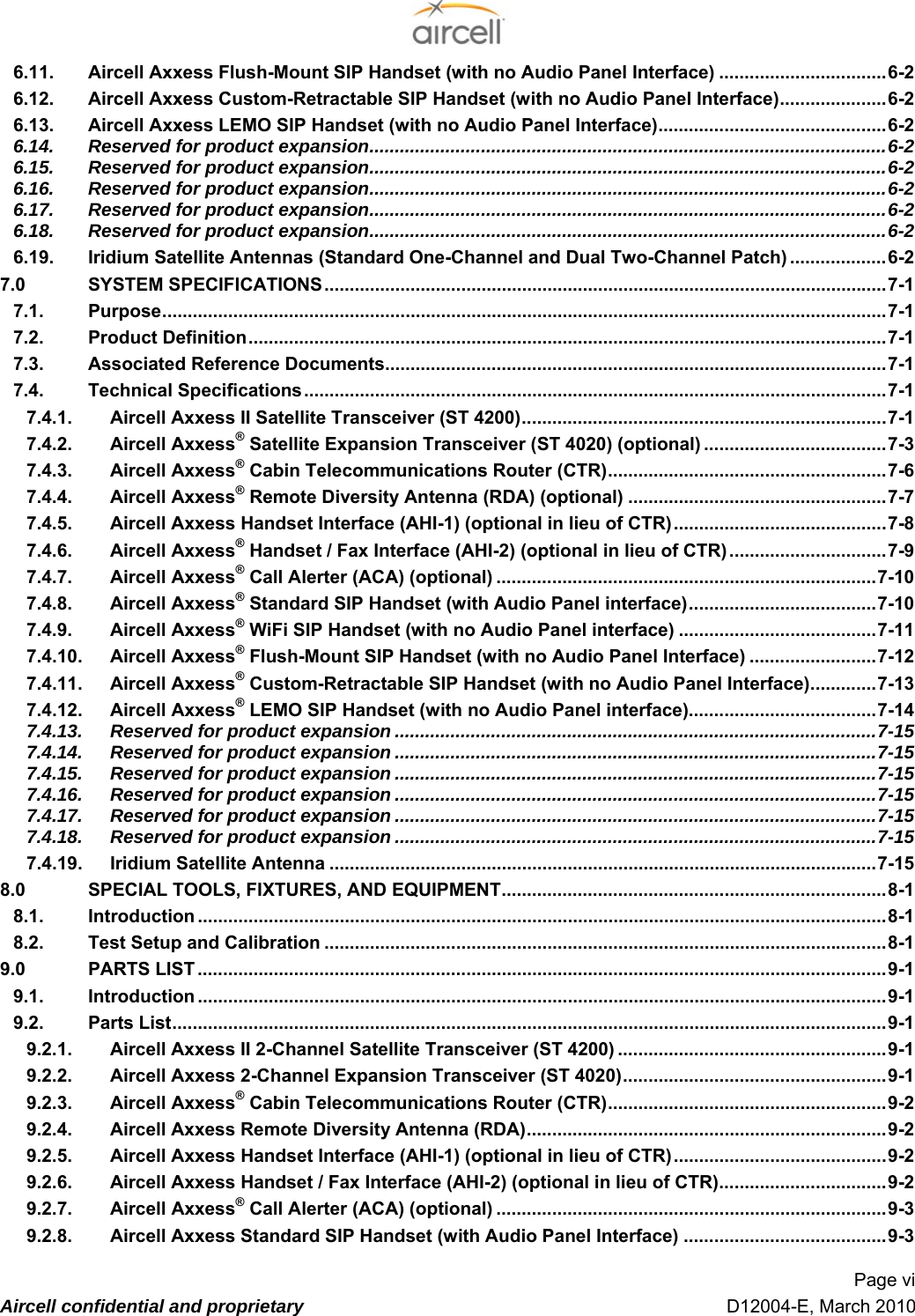

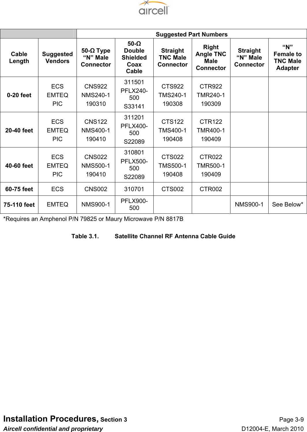
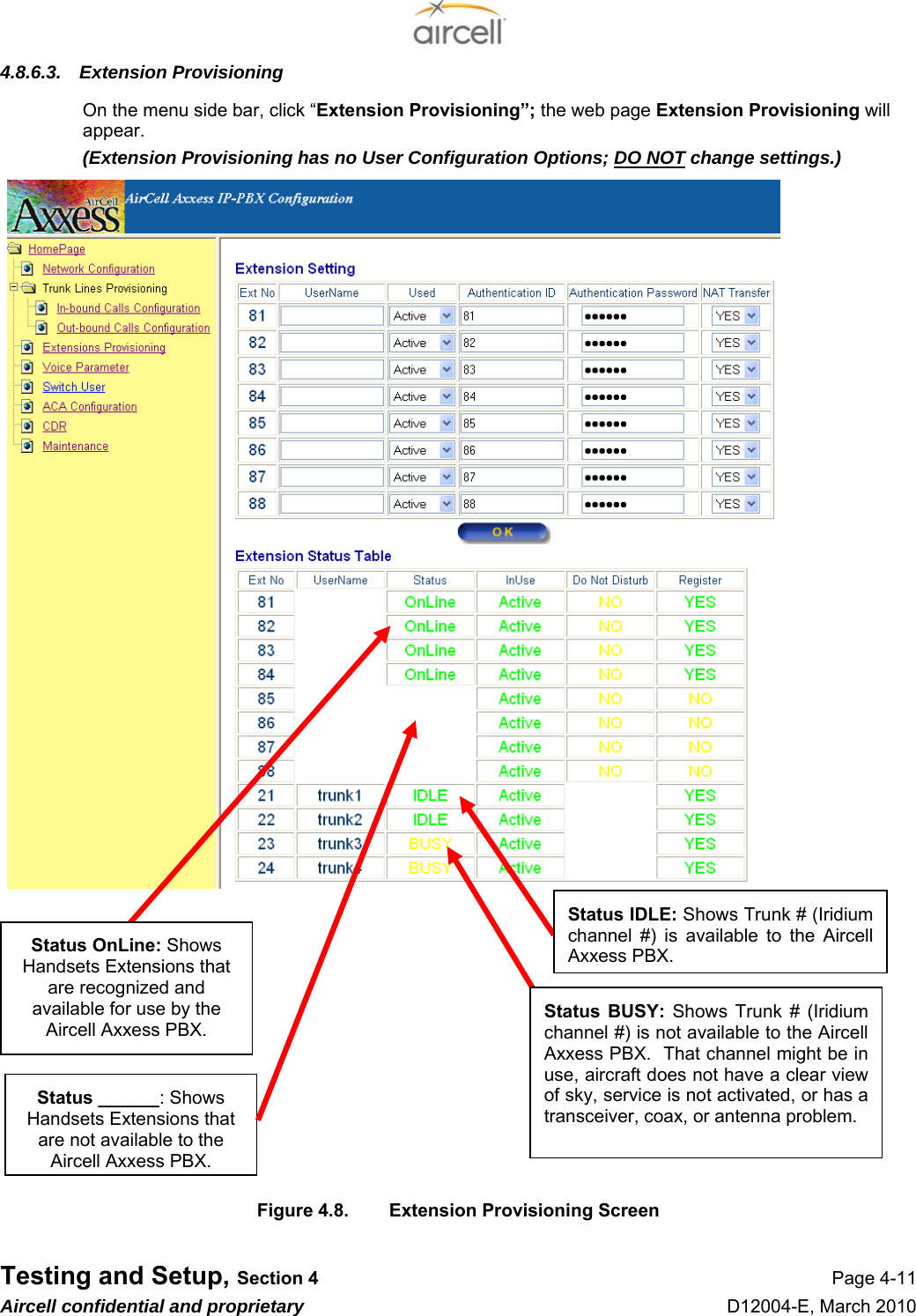
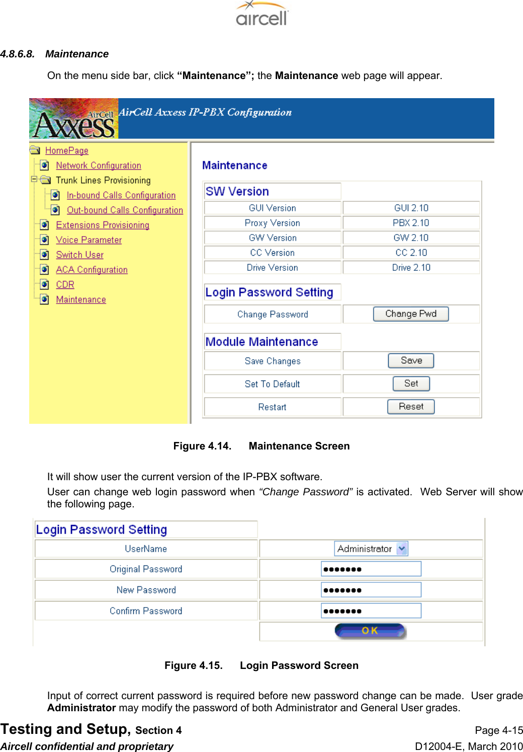
![Testing and Setup, Section 4 Page 4-10 Aircell confidential and proprietary D12004-E, March 2010 4.8.6.2. Out-bound Calls Configuration On the menu side bar, click “Out-bound Calls Configuration”; the Out-bound Calls Configuration web page will appear. Figure 4.7. Out-bound Calls Configuration Web Page The definitions of the Out-bound Calls Configuration parameters in the Configuration Menu are: Access Digit Numbers 0, 1, 2, 3, 4, 5, 6, 7, 8, or 9 allows calls to be outbound /gives outbound access call is an outbound call. Otherwise the current call is inter-com call. Changes are saved after pushing the button “OK” (default is “9”). Priority There are four different priorities [1-4] for each Trunk. The priority 1# is the highest and the priority 4# is the lowest and each Trunk has different priority. If we modify a Trunk with priority 1 to priority 2, then the Trunk with priority 2 will be changed to priority 1automatically. This rule is used to ensure each Trunk has a different priority. Enable Outgoing “Yes”- enabled for outbound “No” - the opposite (default is “YES”). Ring Group Extensions Extensions that are included in the Ring Group Extensions will use this Trunk to make an outbound call. “OK” saves (default is “ALL EXTENSIONS” checked). Table 4.3. Out-bound Calls Configuration Parameters](https://usermanual.wiki/Gogo-Business-Aviation/SIPWFHS/User-Guide-1417583-Page-54.png)
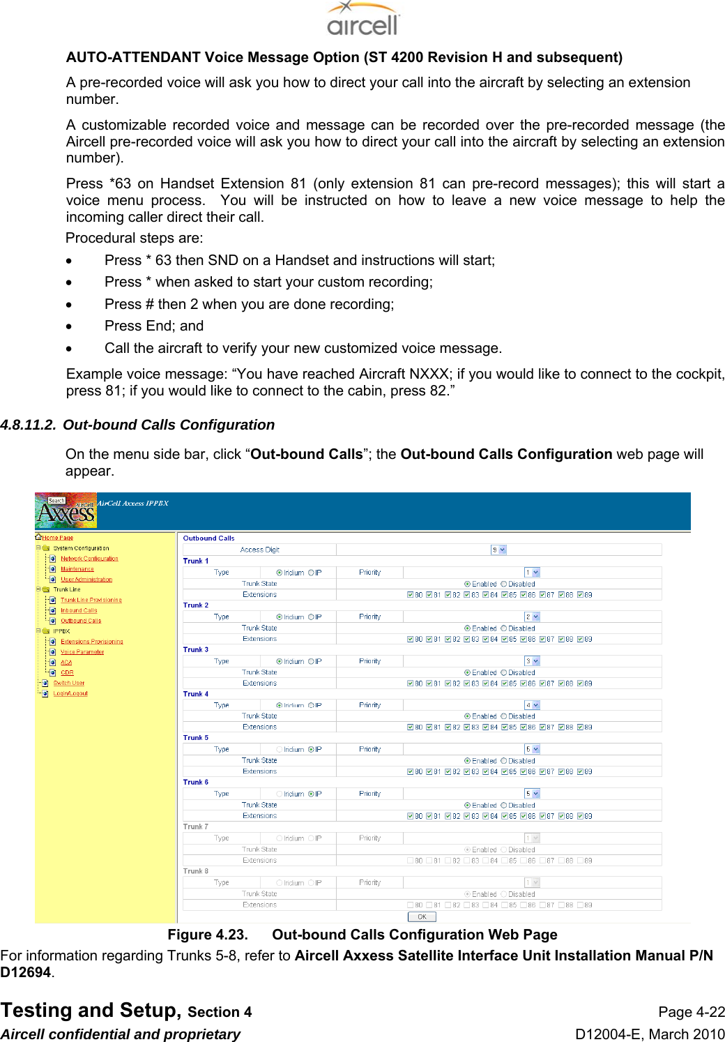
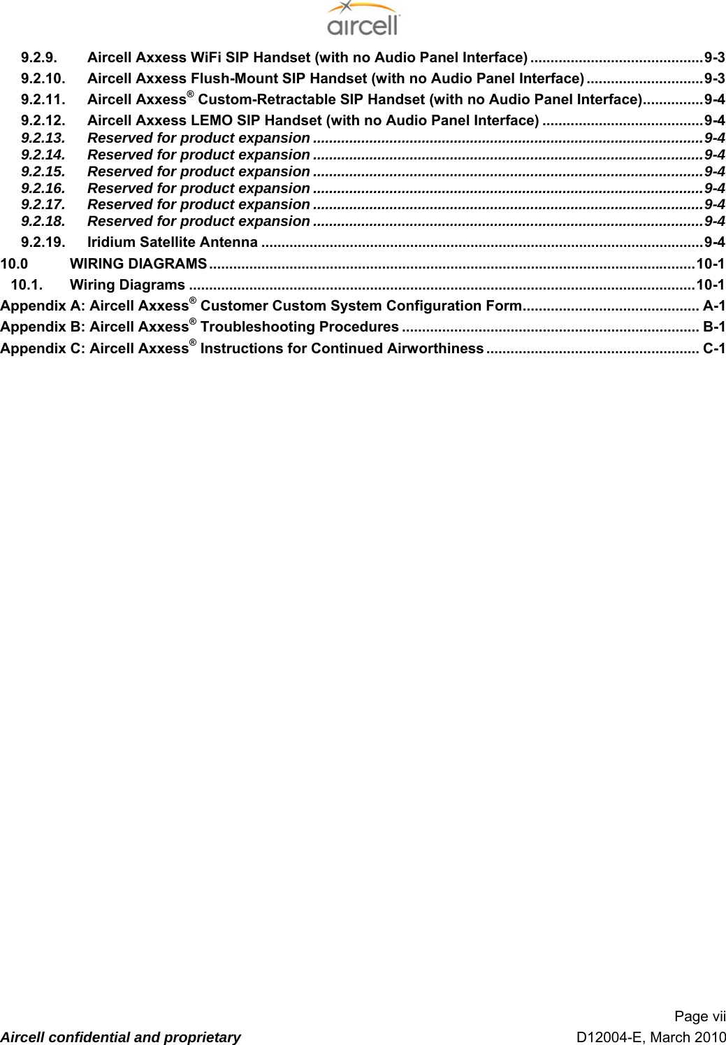
![Testing and Setup, Section 4 Page 4-23 Aircell confidential and proprietary D12004-E, March 2010 The definitions of the Out-bound Calls Configuration parameters in the Configuration Menu are: Access Digit Numbers 0, 1, 2, 3, 4, 5, 6, 7, 8, or 9 allows calls to be outbound /gives outbound access call is an outbound call. Otherwise the current call is inter-com call. Changes are saved after pushing the button “OK” (default is “9”). Priority There are four different priorities [1-4] for each Trunk. The priority 1# is the highest and the priority 4# is the lowest and each Trunkhas different priority. If we modify a Trunk with priority 1 to priority 2, then the Trunk with priority 2 will be changed to priority 1automatically. This rule is used to ensure each Trunk has a different priority. Enable Outgoing “Yes”- enabled for outbound “No” - the opposite (default is “YES”). Ring Group Extensions Extensions that are included in the Ring Group Extensions will use this Trunk to make an outbound call. “OK” saves (default is “ALL EXTENSIONS” checked). Table 4.8. Out-bound Calls Configuration Parameters](https://usermanual.wiki/Gogo-Business-Aviation/SIPWFHS/User-Guide-1417583-Page-67.png)