Golden Mark WD100 Wireless dimmer User Manual

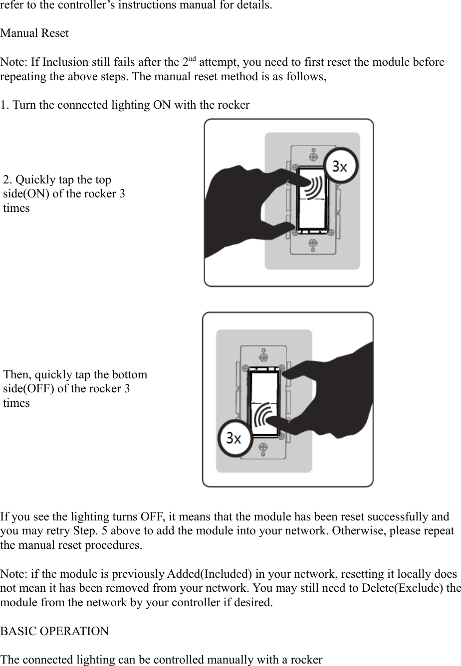
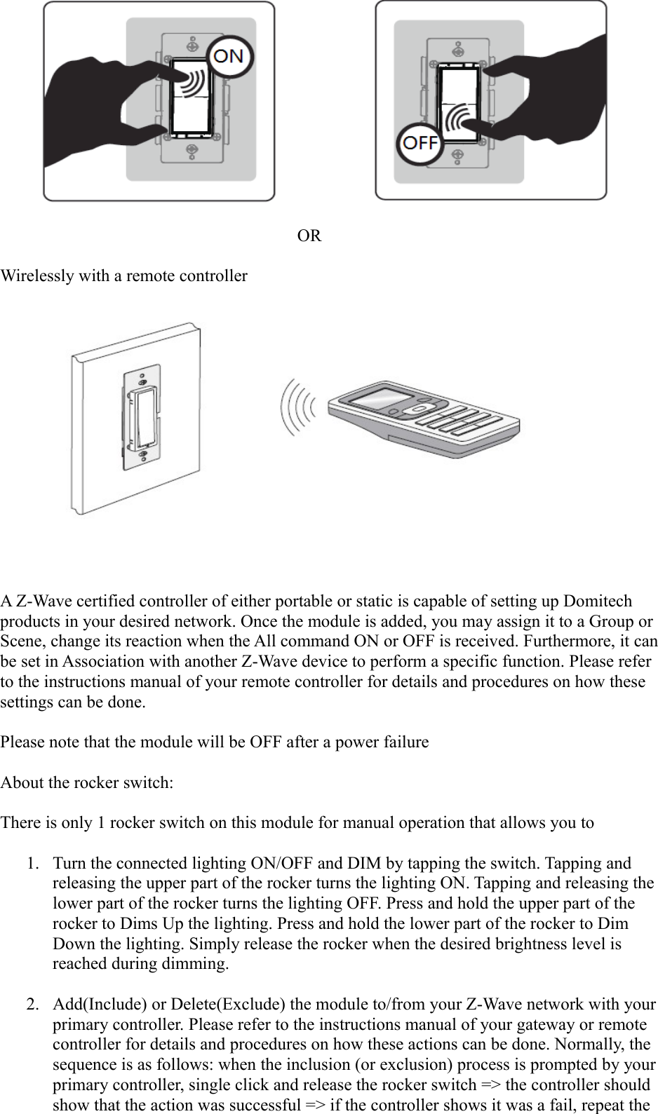
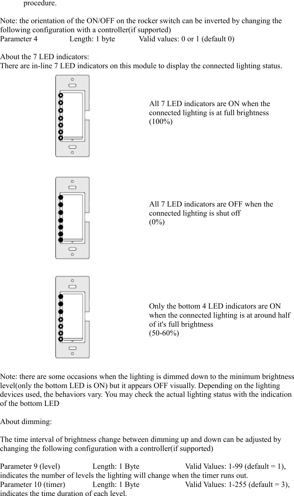
Dragon Tech Industrial Limited Wireless dimmer

User manual

                               This product speaks with other Z-Wave certified devicesWireless Dimmer ModuleWD-100In Wall Dimmer
INTRODUCTIONdomitech™ WD-100 is a member of the Z-Wave® family and communicates with other Z-Wave certified devices in a control network. WD-100 replaces a standard in-wall light switch and turns it into a Z-Wave controlled network device with dimming and On/Off light control. Each Z-Wave device serves as a node to repeat the signal in the network, thus, extending the overall Z-Wave mesh wireless network range. Different types and brands of Z-Wave devices can be associated with Domitech WD-100 in your system and they will work together to optimize and expand the coverage of your Z-Wave network. Once setup is completed, you can enjoy the convenience and leisure which WD-100 offers.FEATURESWorks with incandescent and dimmable florescent (CFL), or LED lighting7 LED indicators for ON/OFF/Dimming level statusCan be controlled wirelessly or manuallyFits into standard single or multiple gang junction box and  standard wall platesGROUP/SCENE/ALL enabledDecorative keypad can be replaced manually to match color with other wall switches Over-The-Air firmware upgrade available with compatible gateway, Z-Wave static controller, PC and softwareZ-Wave 500 Series module insideInternal resettable fuse to protect from surge currentManual reset capability! WARNING !RISK OF FIRE, ELECTRICAL SHOCK & BURNSDO NOT USE WITH MEDICAL AND LIFE SUPPORT INSTRUMENT No user serviceable parts are in this moduleThe lighting connected to the WD-100 must not exceed 600W incandescent, 150W dimmableCFL/LED. CAUTION: To Reduce the Risk of Overheating And Possible Damage To Other Equipment,
Do Not Install To Control A Receptacle, A Motor-Operated Appliance, A Non-Dimmable Fluorescent Lighting Fixture, Or A Transformer-Supplied Appliance  The color of the keypad switch is changeable by the following method,1. Lift the air gap switch up to avoid electrical shock2. Push side tabs in and lift the cover plate up to release3. Align the tabs of the replacement coverplate and push to snapin 4. Push the air gap switch back downSETUPStep 1. Identifying the wiring terminals on the module
Step 2. ! WARNING ! RISK OF SHOCK ! Make sure power is OFF before wiring !Step 3. Remove the wall plate and the existing switch(if mounted) at your preferred installation location. You may label the wires connected to the screw terminals before disconnecting the switch. Please check that the wiring configuration below is present in the wall switch box, otherwise consult a qualified electrician.
4 wires for 2-way circuit5 wires for 3-way circuit1. Line(Hot) - Black2. Neutral - White3. Ground – Green or Bare4. Traveler (3-way) Red or Other5. Load - BlackWiring InformationUse copper wires onlyUL specification: the tightening torque for the screws is 14 Kgf-cm (12 lbf-in)Strip insulation 5/8" (16mm)Wire connection can be made either to 14 AWG or larger rated at least 80°C14 AWG rated at least 80°C2-way circuit
Making connectionsThe Traveler terminal is not used in a 2-way circuit. Do not remove the insulation tape on the Traveler terminal in this application3-way circuit
Making connectionsPlease refer to WA-100 user manual for wiring instructions of the associating switch. The maximum length of Traveler wire may not exceed 250ft.
Gang BoxTo install the WD-100 in a gang or J box, the tabs on the sides of the metal yoke may need to be removed. For single gang switch, no changes should be required.  For dual or higher gang configuration where switches arenext to each other, the tabs need to be removed.  Simply take a pair of pliers, grab the tabs and wiggle until the tabs break off.This will lower the electrical rating of the module. Please refer to the following details 1x gang boxrating: 600W incandescent150W dimmable CFL/LEDwith 2 side tabs2x gang boxrating: 500W incandescent125W dimmable CFL/LEDwith 1 side tabs3x gang boxrating: 400W incandescent100W dimmable CFL/LEDwith no side tabsStep 4. When proper wiring is completed, secure the module to the wall box. Restore power to the circuit to test if the connected lighting can be turned ON/OFF/Dim manually by the rocker on the module before remounting the wall plate. Also observe the status change of the LED indicators to ensure the module is in normal operating mode. If WA-100 Auxiliary Switch is used for a 3-way connection, please also test if it can control the lighting.  Step 5. Add(Include) the module into your network by a Z-Wave certified controller. Please
refer to the controller’s instructions manual for details.Manual ResetNote: If Inclusion still fails after the 2nd attempt, you need to first reset the module before repeating the above steps. The manual reset method is as follows,1. Turn the connected lighting ON with the rocker2. Quickly tap the top side(ON) of the rocker 3 timesThen, quickly tap the bottomside(OFF) of the rocker 3 timesIf you see the lighting turns OFF, it means that the module has been reset successfully and you may retry Step. 5 above to add the module into your network. Otherwise, please repeat the manual reset procedures.                                           Note: if the module is previously Added(Included) in your network, resetting it locally does not mean it has been removed from your network. You may still need to Delete(Exclude) the module from the network by your controller if desired.  BASIC OPERATIONThe connected lighting can be controlled manually with a rocker
                                                             ORWirelessly with a remote controllerA Z-Wave certified controller of either portable or static is capable of setting up Domitech products in your desired network. Once the module is added, you may assign it to a Group or Scene, change its reaction when the All command ON or OFF is received. Furthermore, it canbe set in Association with another Z-Wave device to perform a specific function. Please refer to the instructions manual of your remote controller for details and procedures on how these settings can be done. Please note that the module will be OFF after a power failureAbout the rocker switch:There is only 1 rocker switch on this module for manual operation that allows you to1. Turn the connected lighting ON/OFF and DIM by tapping the switch. Tapping and releasing the upper part of the rocker turns the lighting ON. Tapping and releasing the lower part of the rocker turns the lighting OFF. Press and hold the upper part of the rocker to Dims Up the lighting. Press and hold the lower part of the rocker to Dim Down the lighting. Simply release the rocker when the desired brightness level is reached during dimming.2. Add(Include) or Delete(Exclude) the module to/from your Z-Wave network with yourprimary controller. Please refer to the instructions manual of your gateway or remote controller for details and procedures on how these actions can be done. Normally, the sequence is as follows: when the inclusion (or exclusion) process is prompted by yourprimary controller, single click and release the rocker switch => the controller should show that the action was successful => if the controller shows it was a fail, repeat the
procedure.Note: the orientation of the ON/OFF on the rocker switch can be inverted by changing the following configuration with a controller(if supported)Parameter 4 Length: 1 byte Valid values: 0 or 1 (default 0)About the 7 LED indicators:There are in-line 7 LED indicators on this module to display the connected lighting status.  All 7 LED indicators are ON when the connected lighting is at full brightness (100%)All 7 LED indicators are OFF when the connected lighting is shut off(0%)Only the bottom 4 LED indicators are ON when the connected lighting is at around half of it's full brightness(50-60%)Note: there are some occasions when the lighting is dimmed down to the minimum brightnesslevel(only the bottom LED is ON) but it appears OFF visually. Depending on the lighting devices used, the behaviors vary. You may check the actual lighting status with the indication of the bottom LED  About dimming:The time interval of brightness change between dimming up and down can be adjusted by changing the following configuration with a controller(if supported)Parameter 9 (level) Length: 1 Byte Valid Values: 1-99 (default = 1), indicates the number of levels the lighting will change when the timer runs out.        Parameter 10 (timer) Length: 1 Byte Valid Values: 1-255 (default = 3), indicates the time duration of each level.
The resolution is 10 milliseconds. For example, a default value of 3 means the timer runs out every 30 milliseconds. Using the combinations of these 2 parameters, you can create a dim rate adjustment range as short as 10 milliseconds to a very slow dim rate. About the Z-Wave 500 Series module: You can use a Z-Wave certified portable or static controller to communicate with the module. Depending on the capability of your controller or gateway software, the following simple to advanced operations can be performed. Please refer to the controller's or gateway manual for details.1. Turn the connected lighting On/Off and Dim2. Add(Include) or Delete(Exclude) your WD-100 to/from your network3. Assign your WD-100 to a specific Group/Scene and/or to include your WD-100 as part of your All ON or OFF command4. Over-the-Air firmware update by your gateway or static controller5. Lifeline function which automatically notifies the associated modules and the networkthat a manually reset device is no longer in the network, thus, the corresponding association becomes invalidSPECIFICATIONSModel: WD-100Input power: 120 VAC, 60 Hz.Max output loading: 1x gang box 600W incandescent, 150W dimmable CFL/LED2x gang box 500W incandescent, 125W dimmable CFL/LED3x gang box 400W incandescent, 100W dimmable CFL/LED Radio frequency: 908.4 MHz/916 MHz.Wireless range: up to 130ft line of sight between the controller and the other available nodes.Normal operating temperature: 77°F (25°C)For indoor use only.Interoperability with Z-Wave devicesA Z-Wave network can integrate devices from various classes of products, and these devices can be made by different manufacturers. The domitech product introduced in this instructions manual has a Z-Wave certification which guarantees such an interoperability. FCC ID: 2ABWCWD100The Federal Communication Commission Radio Frequency Interference Statement includes the following paragraph:The equipment has been tested and found to comply with the limits for a Class B Digital Device, pursuant to part 15 of the FCC Rules. These limits are designed to provide reasonableprotection against harmful interference in a residential installation. This equipment uses, generates and can radiate radio frequency energy and, if not installed and used in accordance with the instruction, may cause harmful interference to radio communication. However, there is no guarantee that interference will not occur in a particular installation. If this equipment does cause harmful interference to radio or television reception, which can be determined by turning the equipment off and on, the user is encouraged to try to correct the interference by one or more of the following measures:Reorient or relocate the receiving antennaIncrease the separation between the equipment and receiver
Connect the equipment into an outlet on a circuit different from that to which the receiver is connectedConsult the dealer or an experienced radio/TV technician for helpOperation is subject to the following two conditions:This device may not cause interferenceThis device must accept any interference, including interference that may cause undesired operation of the device.Important Note: To comply with the FCC RF exposure compliance requirements, no change to the antenna or the device is permitted. Any change to the antenna or the device could resultin the device exceeding the RF exposure requirements and void user’s authority to operate thedevice.Caution: Exposure to Radio Frequency Radiation. To comply with FCC/IC RF exposure compliance requirements, a separation distance of at least 20 cm must be maintained betweenthe antenna of this device and all persons. This device must not be co-located or operating in conjunction with any other antenna or transmitter.IC: 11786A-WD100This device complies with Industry Canada license-exempt RSS standard(s). Operation is subject to the following two conditions: (1) this device may not cause interference, and(2) this device must accept any interference, including interference that may cause undesired operation of the device.Z-Wave is a registered trademark of Sigma DesignWARRANTYdomitech warrants to the original purchaser of this product that for the warranty period, this product will be free from material defects in materials and workmanship. The foregoing warranty is subject to the proper installation, operation and maintenance of the product in accordance with installation instructions and the operating manual supplied to customer. Warranty claims must be made by customer in writing within 30 days of the manifestation of a problem. domitech's sole obligation under the foregoing warranty is to repair, replace or correct any such defect that was present at the time of delivery, or to remove the product and to refund the purchase price to customer. The warranty does not extend to consequential or incidental damage to other products that may be used with this product. For inquiry and customer service, email to support@dragontechind.comAll brand names shown are trademarks of their respective ownersWarranty period: limited 1 year from date of purchase   domitech Products2140 E. Southlake Blvd., Suite L-312Southlake, TX  76092WS100_07022014_En_v1.1

Navigation menu