Good Way Technology FW2440 4-Port Serial Device Server User Manual Manual
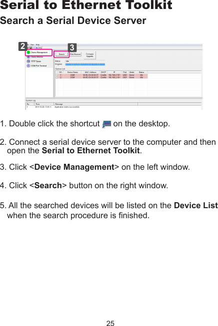
Good Way Technology Co., Ltd. 4-Port Serial Device Server Manual
UserManual.wiki
>
Good Way Technology
>
FW2440 User Manual
Manual
Navigation menu
Upload a User Manual
Namespaces
Wiki Guide
HTML
PDF
Info
Views
User Manual
Discussion / Help
Navigation

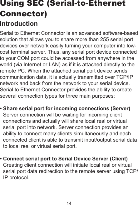
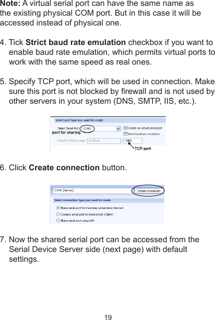
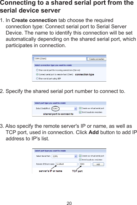
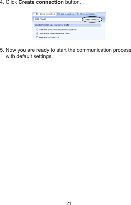
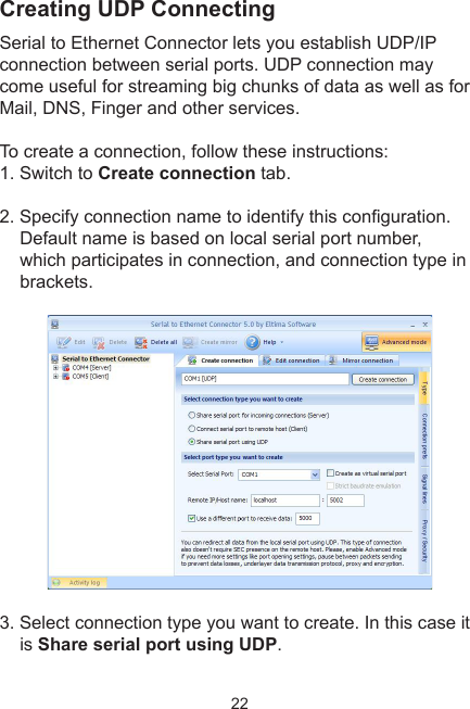
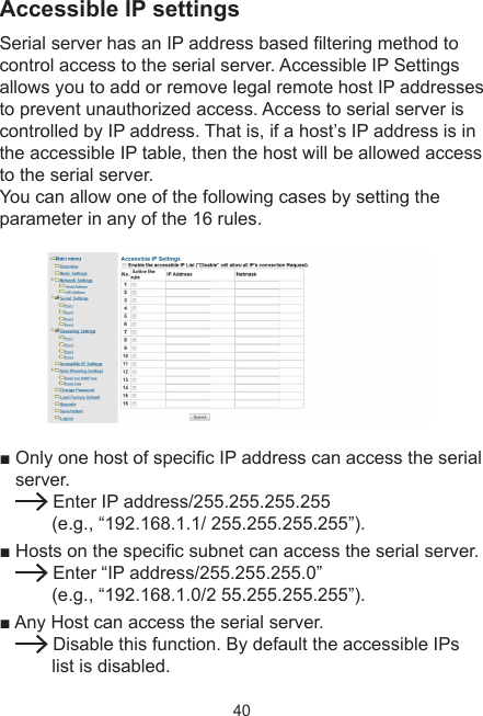
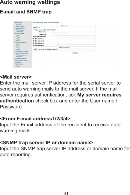
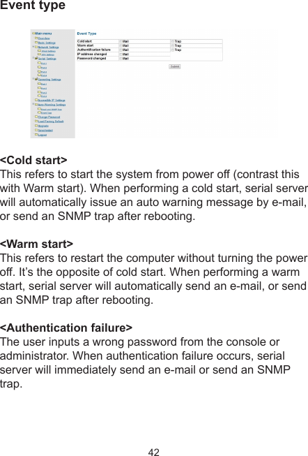
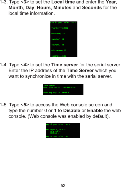
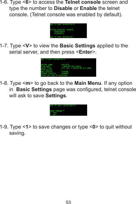
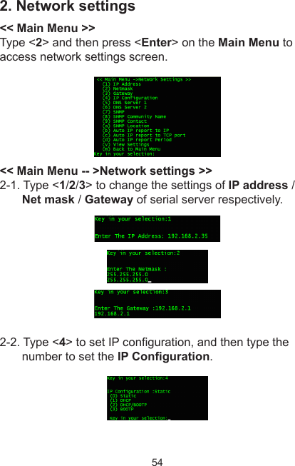
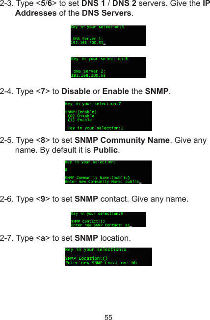
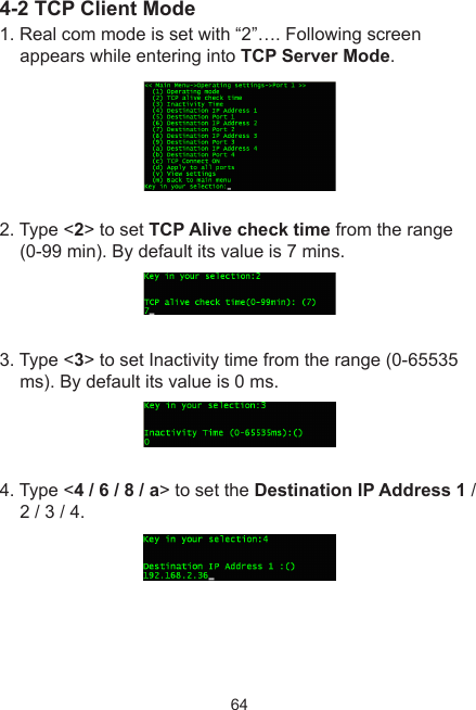
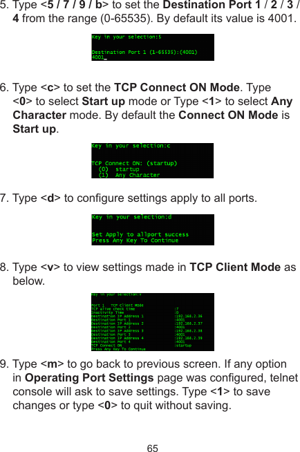
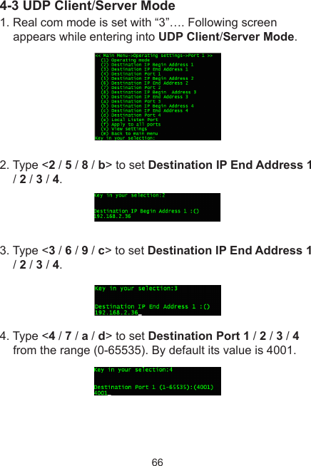
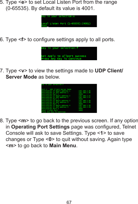
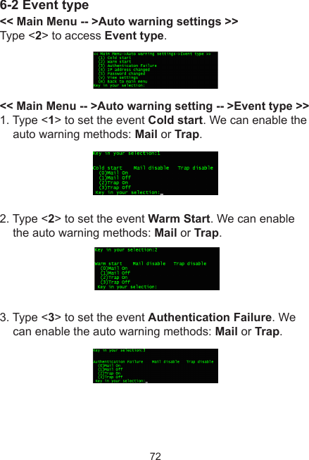
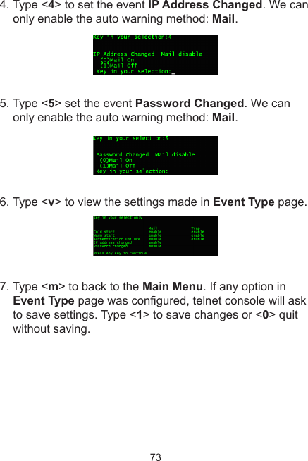
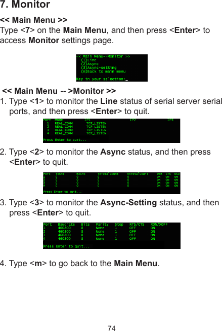
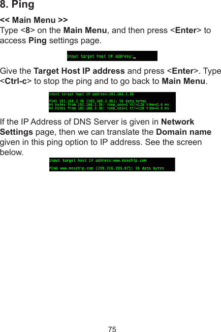
![18Quick starting guideThis guide will take you through the process of establishing client-server connection over TCP/IP network. To launch the Serial to Ethernet Connector, double click the shortcut on the desktop.Sharing a local serial port on PC1. In Create connection tab choose the required connection type: Share serial port for incoming connections (Server). Also specify the name to identify this connection, for instance, COM1 [Server]2. Select local serial port to be shared. For example, COM1 Note: A serial port name must not contain spaces inside.3. Tick Create as virtual serial port checkbox to use a virtual serial port instead of a real one. The advantage of virtual serial ports technology is that you are not limited to the number of physical serial ports in a system, and thus you can free existing serial ports for other applications.](https://usermanual.wiki/Good-Way-Technology/FW2440/User-Guide-1673068-Page-18.png)