Good Way Technology FW2440 4-Port Serial Device Server User Manual Manual
Good Way Technology Co., Ltd. 4-Port Serial Device Server Manual
Manual

4-Port Wireless
Serial Device Server
User's ManualUser's Manual
2
Table of Contents ......................2
Safety Instructions ....................3
Copyright ....................................3
Trademarks ................................3
Introduction ................................4
Features......................................4
Package contents ......................5
System requirement ..................5
Product overview.......................6
Connection .................................7
- Power connection ..................... 7
- Network connection .................. 9
DIN mounting kit installation ..
................................................... 12
Pin assignment ........................ 13
- RJ45 Pin assignment ............. 13
- DB9 Pin assignment ............... 13
Using SEC (Serial-to-Ethernet
Connector) ............................... 14
- Introduction............................. 14
- Driver installation .................... 16
- Uninstall the software ............. 17
Quick starting guide ................ 18
- Sharing a local serial port on PC
................................................ 18
- Connecting to a shared serial
port from the serial device server
................................................ 20
- Creating UDP Connecting ...... 22
Serial to Ethernet Toolkit ........ 25
- Search a Serial Device Server
................................................ 25
Web console ............................26
- Network settings ..................... 27
- WiFi settings ........................... 31
- Serial settings ......................... 32
- Operating settings .................. 34
- Accessible IP settings ............. 40
- Change password .................. 44
- Load factory default ................ 45
- Upgrade.................................. 46
- Save/Restart........................... 47
Telnet console .......................... 48
- Main menu.............................. 48
- 1. Basic settings ..................... 50
- 2. Network settings ................. 54
- 3. Serial settings ..................... 57
- 4. Operating settings ............. 60
- 5. Accessible IP settings ......... 68
- 6. Auto warning settings ......... 70
- 7. Monitor ............................... 74
- 8. Ping .................................... 75
- 9. Change password ............. 76
- 10. Load factory defaults ........ 76
Regulatory compliance ........... 77
- FCC conditions ....................... 77
- CE .......................................... 77
- WEEE information .................. 77
Specication ............................ 78
Table of Contents
3
Before attempting to connect, operate or adjust this product, please
save and read the User's Manual completely. The style of the
product shown in this User's Manual may be different from the actual
unit due to various models.
Safety Instructions
Always read the safety instructions carefully:
■ Keep this User’s Manual for future reference
■ Keep this equipment away from humidity
■ If any of the following situation arises, get the equipment
checked by a service technician:
• The equipment has been exposed to moisture.
• The equipment has been dropped and damaged.
• The equipment has obvious sign of breakage.
• The equipment has not been working well or cannot get
it to work according to the User’s Manual.
Copyright
This document contains proprietary information protected
by copyright. All right are reserved. No part of this manual
may be reproduced by any mechanical, electronic or other
means, in any form, without prior written permission of the
manufacturer.
Trademarks
All trademarks and registered trademarks are the property
of their respective owners or companies.
4
Introduction
The serial server supports multiple serial ports and allows
you to control RS232/422/485 serial devices over a TCP/
IP based Ethernet. Both wire and wireless connection are
supported. By specifying the IP Address and the TCP Port
number, a host user can access different serial devices
such as Serial Modems, Serial Thermometers, Magnetic
Card Readers, Barcode Scanners, Data Acquisition
Systems, POS Terminals, industrial PCs etc.. Besides, you
can centralize serial device management and distribute the
management to different users at the same time.
Features
■ WiFi interface support up to 54Mbps link speed
■ Security mode: WEP/WPA/WPA2
■ RS-232/422/485 mode selected by S/W
■ 15KV ESD immunity to serial interface
■ 3KV optical coupling isolation
■ 9~36 VDC wide range power input
■ Versatile operating mode supported, including RealCOM,
TCP Server, TCP Client and UDP
■ 10/100/1000 Mbps Ethernet port for LAN
■ DIN-rail mountable
5
Package contents
■
Serial Device Server
x1
■ CD (Driver & User’s Manual) x1
■ Power adapter x1
■ DIN mounting kit x1
■ Screw x3
■ RJ45 to DB9 Cable x4
■ Power Terminal Connector x1
System requirement
■ IBM compatible computer
■ Windows Vista ®, Windows XP ® 32/64-bit,
Windows 2000 ®, Windows Server 2008® 32/64-bit
■ 64 MB RAM or higher
■ Pentium® 233 MHz or higher
6
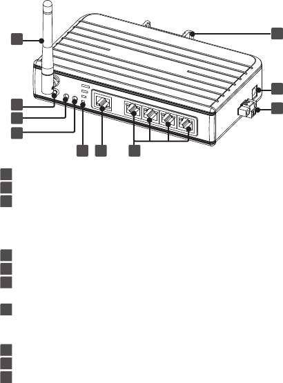
Product overview
1 WiFi antenna
2 Reset button: Presses to restore the factory default settings.
3 Link/Act: ■ Lights green when connecting to an available
network.
■ Flashes green when the wireless data is
transmitting.
4 Power indicator: Lights up when the power is on.
5 Signal strength: Displays the status of WiFi signal strength.
6 RJ-45 Ethernet connector: Connects to an available LAN
(Local area network)
7 RJ-45 connector: Connects to RS232/422/485 devices. For
more detailed pin assignment of RJ45,
refer to Pin assignment chapter.
8 DIN mounting: Attaches to a standard DIN-Rail.
9 5V3A DC Power jack
10 9~36 VDC power terminal
8
10
765
4
3
2
1
9
7
Connection
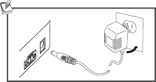
Power connection
To power the serial server, choose one of the below
methods. Power LED lights up when the serial server's
power is on.
DC-In
Plug the supplied power adapter into a wall outlet and the
other end to the serial server's DC power jack.
8
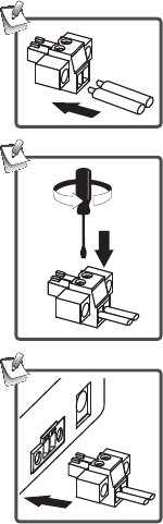
Power cable
1. Insert the cable into the power
terminal block.
2. Tighten the screw using
screwdriver.
3. Plug the power terminal block into
the serial server according to the
connector's orientation.
9
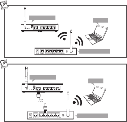
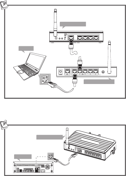
Network connection
This serial server supports to connect an available LAN
(Local Area Network) using wire or wireless. Select one of
the following methods to connect the serial server. Note that
the connection diagrams show below are examples only. The
real applications may be different from the actual conditions.
Wireless connection
Wireless
Wireless
Serial server Laptop
Wireless router
Cable
Wireless
Wireless router
Laptop
Serial server
The device of router can be a DSL router, Ethernet Hub/Switch
or 802.11x router/base station.
10
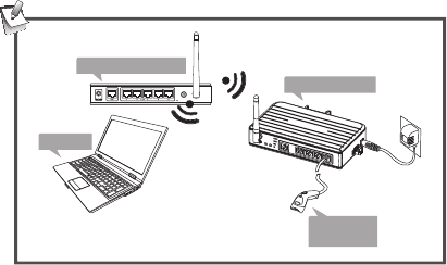
Wire connection
Cable
Cable
Serial server
Laptop
Wireless router
PC connection
Connect the serial server to a computer using Ethernet
cable directly if you do not have a network.
Cable
Serial server
Desktop
11
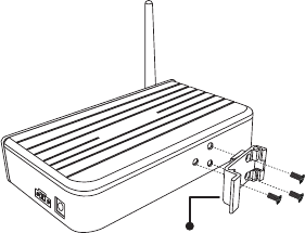
Serial devices connection
Connect serial device(s) to the serial server when the
serial server has been connected to a LAN. The supported
serial devices of this serial server are serial modems, serial
thermometers, magnetic card readers, barcode scanners,
data acquisition systems, POS terminals, industrial PCs
etc..
Note: Install the serial device's drivers before connecting to
the serial server is recommended.
Serial server
Laptop
Barcode
scanner
Wireless
Wireless
Wireless router
12
DIN mounting kit installation
This serial server can be placed to a at surface, mounted
on a wall or attached to a standard DIN-Rail. Screw the
DIN mount kit into the hub as the illustration below before
mounting.
DIN mounting kit
Screw x3
13
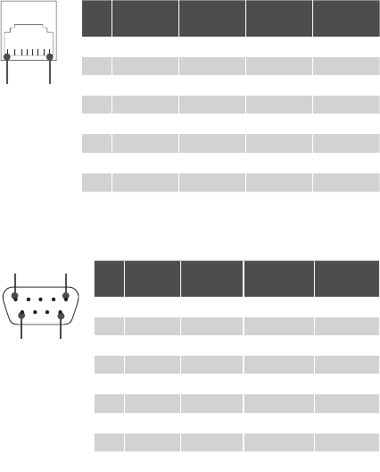
Pin assignment
RJ45 Pin assignment
Pin RS-232 RS-422 RS-485
(4-wire)
RS-485
(2-wire)
1 DSR RXD- RXD- ---
2RTS RXD+ RXD+ ---
3 GND GND GND GND
4 TXD --- --- ---
5 RXD --- --- ---
6 DCD TXD- TXD- Data-
7 CTS --- --- ---
8 DTR TXD+ TXD+ Data+
8 1
DB9 Pin assignment
Pin RS-232 RS-422 RS-485
(4-wire)
RS-485
(2-wire)
1 DCD TxD-(A) TxD-(A) Data-(A)
2RxD --- --- ---
3TxD --- --- ---
4 DTR TxD+(B) TxD+(B) Data+(B)
5 GND GND GND ---
6 DSR RxD-(A) RxD-(A) ---
7RTS RxD+(B) RxD+(B) ---
8 CTS --- --- ---
9 --- --- --- ---
1 5
6 9
14
Using SEC (Serial-to-Ethernet
Connector)
Introduction
Serial to Ethernet Connector is an advanced software-based
solution that allows you to share more than 255 serial port
devices over network easily turning your computer into low-
cost terminal server. Thus, any serial port device connected
to your COM port could be accessed from anywhere in the
world (via Internet or LAN) as if it is attached directly to the
remote PC. When the attached serial port device sends
communication data, it is actually transmitted over TCP/IP
network and back from the network to your serial device.
Serial to Ethernet Connector provides the ability to create
several connection types for three main purposes:
• Share serial port for incoming connections (Server)
Server connection will be waiting for incoming client
connections and actually will share local real or virtual
serial port into network. Server connection provides an
ability to connect many clients simultaneously and each
connected client is able to transmit input/output serial data
to local real or virtual serial port.
• Connect serial port to Serial Device Server (Client)
Creating client connection will initiate local real or virtual
serial port data redirection to the remote server using TCP/
IP protocol.
15
You have to do is specify remote server's IP address
(or network name) and TCP port to connect to. Once
connection is established, all data sent from remote serial
port device, attached to the server, will be genuinely
delivered to local serial port where it can be further
processed.
• Share serial port using UDP
You can redirect input/output data from local real or virtual
serial port using UDP/IP underlay protocol. Besides, you
are able to broadcast all serial data to your local network.
16
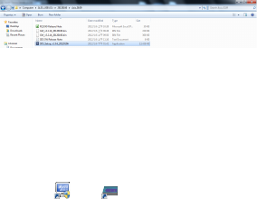
Driver installation
1. Double click SDS_Setup in order to start installation
process.
Note: This driver combines the utilities of Serial to Ethernet
Connector and Serial to Ethernet Toolkit. Both utilities will
be installed to the computer after running the installation.
2. Follow the on-sereen instructions to complete the
installation. Once the installation has been completed,
Two shortcuts ( and ) will appear on the desktop. To
launch the utility, double-click the shortcut which created
on the desktop. Alternatively, navigate the Start menu
and locate the launcher in Programs submenu.
Note: Please install the utility before connecting the serial
server to a computer.
17
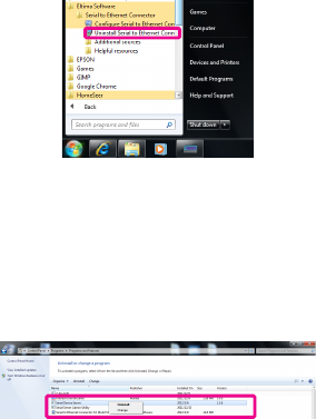
Uninstall the software
Uninstall the Serial to Ethernet Connector
To uninstall the Uninstall Serial to Ethernet Connector,
click on Uninstall Serial to Ethernet Connector under
Ethernet Software item in Programs submenu, and then
follow the on-screen instructions.
Uninstall the Serial to Ethernet Toolkit
1. To uninstall the Serial to Ethernet Toolkit, click Control
Panel in Programs submenu.
2. Click Uninstall a program under Program > right click
on Select Serial Device Server to bring up Uninstall.
18
Quick starting guide
This guide will take you through the process of establishing
client-server connection over TCP/IP network. To launch the
Serial to Ethernet Connector, double click the shortcut
on the desktop.
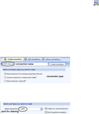
Sharing a local serial port on PC
1. In Create connection tab choose the required connection
type: Share serial port for incoming connections (Server).
Also specify the name to identify this connection, for
instance, COM1 [Server]
2. Select local serial port to be shared. For example, COM1
Note: A serial port name must not contain spaces inside.
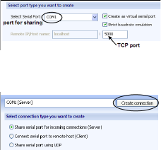
3. Tick Create as virtual serial port checkbox to use a
virtual serial port instead of a real one. The advantage of
virtual serial ports technology is that you are not limited to
the number of physical serial ports in a system, and thus
you can free existing serial ports for other applications.
19
Note: A virtual serial port can have the same name as
the existing physical COM port. But in this case it will be
accessed instead of physical one.
4. Tick Strict baud rate emulation checkbox if you want to
enable baud rate emulation, which permits virtual ports to
work with the same speed as real ones.
5. Specify TCP port, which will be used in connection. Make
sure this port is not blocked by rewall and is not used by
other servers in your system (DNS, SMTP, IIS, etc.).
6. Click Create connection button.
7. Now the shared serial port can be accessed from the
Serial Device Server side (next page) with default
settings.
20
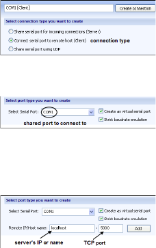
Connecting to a shared serial port from the
serial device server
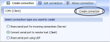
1. In Create connection tab choose the required
connection type: Connect serial port to Serial Server
Device. The name to identify this connection will be set
automatically depending on the shared serial port, which
participates in connection.
2. Specify the shared serial port number to connect to.
3. Also specify the remote server's IP or name, as well as
TCP port, used in connection. Click Add button to add IP
address to IP's list.
21
4. Сlick Create connection button.
5. Now you are ready to start the communication process
with default settings.
22
Creating UDP Connecting
Serial to Ethernet Connector lets you establish UDP/IP
connection between serial ports. UDP connection may
come useful for streaming big chunks of data as well as for
Mail, DNS, Finger and other services.
To create a connection, follow these instructions:
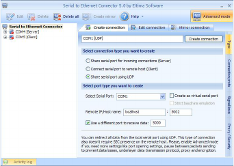
1. Switch to Create connection tab.
2. Specify connection name to identify this conguration.
Default name is based on local serial port number,
which participates in connection, and connection type in
brackets.
3. Select connection type you want to create. In this case it
is Share serial port using UDP.
23
4. In Select Serial Port eld choose local serial port which
will participate in connection: either add it manually, or
select one from the drop-down list.
5. Tick Create as virtual serial port option if you would like
to use virtual serial ports instead of real ones.
6. Tick Strict baud rate emulation checkbox if you want
to enable baud rate emulation. You can nd more details
about our virtual serial port and baud rate emulation
technologies here.
7. Specify IP address (or network name) of the remote end
and port number to connect to. Make sure that the port
numbers are the same at both ends and are not blocked
by rewall.
8. You can also specify the port to receive the data,
regardless of the port the data is sent to. It may be useful
if you create UDP connection with several devices that
have the same ports.
9. Finally, click Create connection button. Once connection
is created, you can see it in Connections tree.
10. Open local serial port. You may use Windows
HyperTerminal utility for this purpose. This step is
necessary only if you want to verify whether the
connection was created successfully.
24
11. Create UDP connection at the remote end. Repeat steps
1-10 listed above. Make sure that the port numbers are
the same at both ends and are not blocked by rewall.
12. Now you are ready to start communication process with
default settings. You can refer to Editing UDP connection
section if you would like to edit a newly established
connection.
25
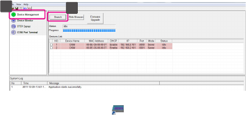
Serial to Ethernet Toolkit
Search a Serial Device Server
23
1. Double click the shortcut on the desktop.
2. Connect a serial device server to the computer and then
open the Serial to Ethernet Toolkit.
3. Click <Device Management> on the left window.
4. Click <Search> button on the right window.
5. All the searched devices will be listed on the Device List
when the search procedure is nished.
26
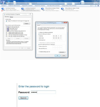
Web console
This Serial server supports the remote conguration using
web console on the network. To use the web console, open
a web browser (eg., Internet Explorer) and type the IP
address which you have set in the Network and Sharing
Center (string example of Windows 7®, the actual string is
depending on your operating system).
Note: Congure the IP address to 192.168.3.X where
the X is between 2 and 254. To set up your computer's IP
address, refer to the operating system's instruction manual.
Login the web console, and then click Submit. By default,
the password is admin.
27
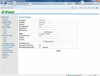
Network settings
Network settings are used to setup network parameters for
serial server. User must assign a valid IP address to serial
server. Network system administrator will provide you with
an IP address and related settings for the network. The
IP address must be unique within the network (otherwise,
serial server will not have a valid connection to the network).
28
IP Address
An IP address is a number assigned to a serial server.
Computers use the IP address to identify and communicate
with the device over the Network. Choose a proper IP
address which is unique and valid in the network.
By default, the IP address is 192.168.3.22
Default Net Mask will be 255.255.255.0
Default Gateway is 192.168.3.1
IP Conguration
There are four possible IP Conguration modes, Static,
DHCP, BOOTPM and DHCP/BOOTP respectively. These
modes are located under the web console screen’s IP
conguration drop-down box In dynamic IP environments.
The rmware will retry 3 times every 30 seconds until
Network Settings are assigned by the DHCP or BOOTP
server. The timeout for each try increases from 1 second, to
3 seconds, to 5 seconds. If the DHCP/BOOTP server is
unavailable, the rmware will use the default IP Address,
192.168.3.22, Net mask, and Gateway for IP settings. The
factory default is Static.
29
DNS Server 1/ DNS Server 2
In order to use serial server’s DNS feature, you need to set
the IP address of the DNS server to be able to access
the host with the Domain Name. Serial server provides
DNS Server 1 and DNS Server 2 conguration items to
congure the IP address of the DNS Server. DNS Server 2
is included for use when DNS Sever 1 is unavailable. LAN
server plays the role of DNS client. Functions that support
domain name in serial server are Time Sever IP Address,
TCP Client-Destination IP Address, Mail Server, SNMP Trap
IP Address, and IP Location Server.
SNMP Settings
Enable or disable SNMP function. The factory default is
Enable.
Community Name
A community name is a plain-text password mechanism that
is used to weakly authenticate queries to agents of
managed Network Devices. The factory default is Public.
Contact
The SNMP contact information usually includes an
emergency contact name and telephone or pager number.
The factory default is NONE.
Location
Specify the location string for SNMP agents such as serial
server. This string is usually set to the street address where
the serial server is physically located. The factory default is
NONE.
30
IP address report
When serial servers are used in a dynamic IP environment,
users must spend more time with IP management tasks. For
example, serial server works as a server (TCP or UDP), and
the host, which acts as a client, must know the IP address
of the server. If the DHCP server assigns a new IP address
to the server; the host must take care of what happens
when the IP changes. Serial servers help out by periodically
reporting their IP address to the IP Location Server, in case
the dynamic IP has changed. The parameters shown below
are used to congure the Auto IP Report function. There are
two ways to develop an Auto IP Report Server” to receive
serial server’s Auto IP Report.
31
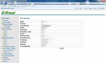
WiFi settings
Mode
• Infra: Connect via an access point
• Adhoc: Direct connect to a PC without an access point.
Scan Routers: Click <Scan Routers> to search the
available wireless LAN(s), and then select a desired
wireless LAN to join.
IP conguration: Enable the DHCP to get an IP address
from the wireless router or disable to change the IP address,
Subnet mask and Default Gateway.
Encryption: OFF and ON.
Key ID: Select a Key ID which you have set on the
connected AP, and then enter the password. The serial
server will detect the security mode automatically.
Note: The password you entered must be the same as
congured on the AP.
32
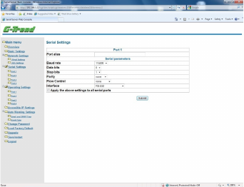
Serial settings
Serial Settings page is used to set serial port parameters
and request for their status.
All of the items mentioned above will reect real-time status.
If its setting is override by some application setting, it will
show the current running setting. To modify serial settings
for a particular port, click on desired port number under
Serial Settings. Those serial port parameters are meaningful
only in multiple connection usage. When used in the single
connection scenario, those setting will be override by
application settings.
33
Port Alias
Port alias is specially designed to allow easy identication
of the aerial devices which are connected to serial server’s
aerial port. The factory default is None and is optional.
Baud rate
Can be set from 110 bps to 921600 bps. The factory default
is 115200 bps.
Data bits
Data bits are 5,6,7,8. The factory default is 8.
Stop bits
Stop bits are 1 ,2. The factory default is 1.
Parity
None, Even, Odd, Space, Mark. The factory default is
None.
Flow control
Supports None, RTS/CTS, DTR/DSR, Xon/ Xoff. The factory
default is None.
Interface: RS-232, RS-485/422 (4-wire), RS-485(2-wire)
34
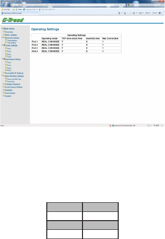
Operating settings
Click Operating Settings to display the operating settings
for all of serial server ports. To congure the desired port,
click from left window under Operating Settings item.
Note: When the Serial server is under REAL COM mode,
the default TCP ports are as follows:
Port 1 1234
Port 2 1235
Port 3 1236
Port 4 1237
35
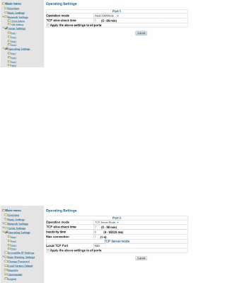
Operation mode
Real COM mode
TCP Alive check time
1 to 99 min: Serial server automatically closes TCP
connection if there is no TCP activity for the given time.
After the connection is closed, serial server starts listening
for another Real COM driver’s connection from another
host. The factory default is 7 minutes.
TCP server mode
TCP Alive check time: The factory default is 7 minutes.
● 0 min: TCP connection is not closed due to an idle TCP
connection.
36
● 1 to 99 min: Serial server automatically closes TCP
connection if there is no TCP activity for the given time.
After the connection is closed, serial server starts listening
for another host’s TCP connection.
Inactivity time (0-65535 ms): The factory default is 0 ms.
● 0 ms: TCP connection is not closed due to an idle Serial
Line.
● 0-65535 ms: serial server automatically closes the
TCP connection if there is no Serial data activity for the
given time. After the connection is closed, Serial Server
starts listening for another host’s TCP connection. This
parameter denes the maintenances status as Closed or
Listen on the TCP connection. The connection is closed
if there is no incoming or outgoing data through the serial
port during the specic Inactivity time.
If the value of inactivity time is set to 0, the current TCP
connection is maintained until there is connection close
request. Although inactivity time is disabled, the serial
server will check the connection status between the serial
server and remote host by sending keep alive packets
periodically. If the remote host does not respond to the
packet, it assumes that the connection was closed down
unintentionally. Serial server will then force the existing
TCP connection to close. To prevent the unintended
loss of data due to the session disconnected, it is highly
recommended that this value is set large enough so that
37
the intended data transfer is completed. Max connection:
The factory default is 1. Max Connection is usually
used when the user needs to receive data from different
hosts simultaneously. The factory default only allows 1
connection at a time.
● Max. Connection 1: Serial server only allows 1 host to
open the TCP connection to the specic serial port.
● Max Connection 2 to 4: Allow 2 to 4 host’s TCP connection
request to open the specic serial server’s serial port,
at the same time. When multiple hosts establish a TCP
connection to the specic serial port at the same time,
serial server will duplicate the serial data and transmit to
all of the hosts. Ethernet data is sent on a rst-in-rst-out
basis to the serial port when data comes into serial server
from the Ethernet interface.
38
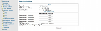
TCP client mode
TCP Alive check time
● 0 min: TCP connection is not closed due to an idle TCP
connection.
● 1 to 99 min: Serial Server automatically closes TCP
connection if there is no TCP activity for the given time.
Inactivity time
● 0 ms: TCP connection is not closed due to an idle serial
line.
● 0-65535 ms: Serial server automatically closes the
TCP connection if there is no serial data activity for the
given time. After the connection is closed, serial server
starts listening for another host’s TCP connection. This
parameter denes the maintenances status as Closed or
Listen on the TCP connection. The connection is closed
if there is no incoming or outgoing data through the
serial port during the specic Inactivity time. If the value
of inactivity time is set to 0, the current TCP connection
is maintained until there is connection close request.
39
Although inactivity time is disabled, the serial server
will check the connection status between the serial
server and remote host by sending keep alive packets
periodically. If the remote host does not respond to the
packet, it assumes that the connection was closed down
unintentionally. Serial server will then force the existing
TCP connection to close.
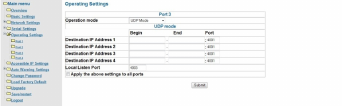
UDP mode
Destination IP Address 1: Setting destination IP address
1, allows serial server to connect actively to the remote host
whose address is set by this parameter.
Destination IP Address 2 / 3 / 4: Destination IP address
2/3/4, allows serial server to connect actively to the remote
host whose address is set by this parameter.
Local Listen Port: The UDP port that serial server listens
to and those other devices must use to contact serial server.
To avoid conicts with well-known UDP ports, the default is
set to 4001.
40
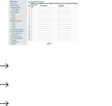
Accessible IP settings
Serial server has an IP address based ltering method to
control access to the serial server. Accessible IP Settings
allows you to add or remove legal remote host IP addresses
to prevent unauthorized access. Access to serial server is
controlled by IP address. That is, if a host’s IP address is in
the accessible IP table, then the host will be allowed access
to the serial server.
You can allow one of the following cases by setting the
parameter in any of the 16 rules.
■ Only one host of specic IP address can access the serial
server.
Enter IP address/255.255.255.255
(e.g., “192.168.1.1/ 255.255.255.255”).
■ Hosts on the specic subnet can access the serial server.
Enter “IP address/255.255.255.0”
(e.g., “192.168.1.0/2 55.255.255.255”).
■ Any Host can access the serial server.
Disable this function. By default the accessible IPs
list is disabled.
41
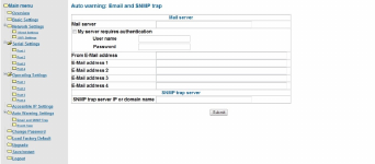
Auto warning wettings
E-mail and SNMP trap
<Mail server>
Enter the mail server IP address for the serial server to
send auto warning mails to the mail server. If the mail
server requires authentication, tick My server requires
authentication check box and enter the User name /
Password.
<From E-mail address1/2/3/4>
Input the Email address of the recipient to receive auto
warning mails.
<SNMP trap server IP or domain name>
Input the SNMP trap server IP address or domain name for
auto reporting.
42
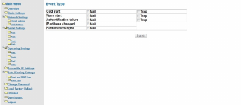
Event type
<Cold start>
This refers to start the system from power off (contrast this
with Warm start). When performing a cold start, serial server
will automatically issue an auto warning message by e-mail,
or send an SNMP trap after rebooting.
<Warm start>
This refers to restart the computer without turning the power
off. It’s the opposite of cold start. When performing a warm
start, serial server will automatically send an e-mail, or send
an SNMP trap after rebooting.
<Authentication failure>
The user inputs a wrong password from the console or
administrator. When authentication failure occurs, serial
server will immediately send an e-mail or send an SNMP
trap.
43
<IP Address changed>
The user has changed serial server’s IP address. When the
IP address changes, serial server will send an e-mail with
the new IP address before serial server reboots.
If the serial server fails to send mail to the mail server after
15 seconds, serial server will be rebooting directly and abort
the mail auto warning.
<Password changed>
The user has changed serial server’s password. When the
password changes , serial server will send an e-mail with
the password change notice before serial server reboots. If
the serial server fails to send mail to the mail server after 15
seconds, serial server will be rebooting directly and abort
the mail auto warning.
<Mail>
This feature helps the administrator manage the serial
server. Serial server sends mail to pre-dened mail boxes
when the enabled events—such as cold start, warm start,
authentication failure, etc.—occur. To congure this feature,
click on the event type box.
<Trap>
This feature helps the administrator manage the serial
server. Serial server send SNMP Trap to a pre-dened
SNMP Trap server when the enabled events—such as cold
start, warm start, authentication failure, etc.—occur. To
congure this feature, you need to click on the event type
box.
44
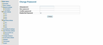
Change password
Input the Old password and New password to change the
password. Leave the password boxes blank to erase the
password.
In this case, the serial server will not have password
protection. If user forgets the password, the ONLY way to
congure serial server is by using the Reset button on serial
server’s casing to Load Factory Default. (default password
is admin)

45
Load factory default
This function will reset all of serial server’s settings to the
factory default values.
The console must prompt the warning message to the users
to notice them that previous settings will be lost.
46
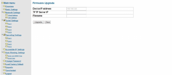
Upgrade
The Upgrade page enables user to upgrade rmware from
web console.
The upgrade option needs a TFTP Server program which
needs to be run on the client PC from where the complete
rmware Image is to be downloaded onto the serial server
board.
The Device IP Address displays the IP address of the serial
server.
Enter the TFTP server IP Address and the Filename of the
update le, and then click Upgrade. The rmware will be
completely upgraded.
47
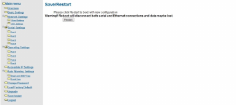
Save/Restart
This function is used to save current setting and automatic
restart the serial server.
Click Submit to save and restart the serial server.
Warning!! Reboot will disconnect both serial and Ethernet
connections and data maybe lost.

48
Telnet console
Serial server implements a telnet server and can be invoked
by making a telnet from remote PC.
1. Enable the Telnet Console function from Windows
Conguration Utility.
2.Go to Start Menu > Run.
3. Run telnet from remote pc with the IP address of serial
server.
Main menu
1. As soon as the telnet console is opened, it comes with an
authentication screen displaying the Model Name, MAC
Address, Serial Number and the Firmware version.
2. Enter the Password.
49
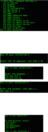
3. The Main menu contains following options
(1) Basic Settings: To congure basic settings like
Server Name, Time Zone, Real Time Clock, Time
server IP address, Enable/Disable Web and Telnet
Consoles.
(2) Network Settings: To congure Network settings like
IP Address, Net mask, Gateway, IP Conguration,
DNS, SNMP and Auto IP Report.
(3) Serial Settings: To congure serial communication
parameters like Baud Rate, Data bits, Stop bits,
Parity and Flow control.
(4) Operating Settings: To congure operating settings
like Operating Mode, TCP Alive Check and
Inactivity.
(5) Accessible IP Settings: To congure accessible IP
settings which allows you to add or remove Legal
remote host IP addresses to prevent unauthorized
access.
(6) Auto Warning Settings: To congure auto warning
settings which sends the status messages to email
id’s and trap servers in order to warn or acknowledge
the changes made in the serial server.
(7) Monitor: To monitor the serial line and sync settings
in order to know the current status of serial server.

50
(8) Ping: To test whether a particular host is reachable
across an IP network.
(9) Password Settings: To congure password settings
like Enable / Disable Password or giving new
password to the serial server.
(a) Load Factory Defaults: To set the serial server to
factory defaults.
(v) View Settings: To view all the settings made in the
serial server.
(s) Save/Restart: To give soft restart.
(q) Quit: To quit from the telnet console.
1. Basic settings
<< Main Menu >>
Type <1> and then press <Enter> on Main Menu screen to
access Basic settings screen.
51
<<Main Menu -- >Basic settings >>
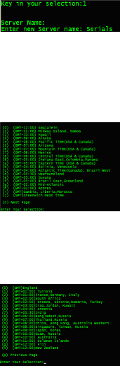
1-1. Type <1> and set the Server Name.
Note that the Server Name should not be more than 7
characters and no space should be allowed between
characters.
1-2. Type <2> to set the Time zone for the serial server.
Select the Time zone for the serial server from the
list displayed. Enter your selection 0-9 or a-j to set the
Time Zone or type <n> to go to next page of Time zone
screen and press <Enter>.
52
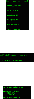
1-3. Type <3> to set the Local time and enter the Year,
Month, Day, Hours, Minutes and Seconds for the
local time information.
1-4. Type <4> to set the Time server for the serial server.
Enter the IP address of the Time Server which you
want to synchronize in time with the serial server.
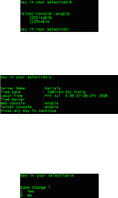
1-5. Type <5> to access the Web console screen and
type the number 0 or 1 to Disable or Enable the web
console. (Web console was enabled by default).
53
1-6. Type <6> to access the Telnet console screen and
type the number to Disable or Enable the telnet
console. (Telnet console was enabled by default).
1-7. Type <V> to view the Basic Settings applied to the
serial server, and then press <Enter>.
1-8. Type <m> to go back to the Main Menu. If any option
in Basic Settings page was congured, telnet console
will ask to save Settings.
1-9. Type <1> to save changes or type <0> to quit without
saving.
54
2. Network settings
<< Main Menu >>
Type <2> and then press <Enter> on the Main Menu to
access network settings screen.
<< Main Menu -- >Network settings >>
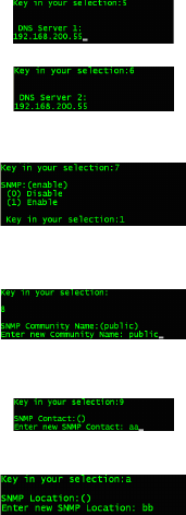
2-1. Type <1/2/3> to change the settings of IP address /
Net mask / Gateway of serial server respectively.
2-2. Type <4> to set IP conguration, and then type the
number to set the IP Conguration.
55
2-3. Type <5/6> to set DNS 1 / DNS 2 servers. Give the IP
Addresses of the DNS Servers.
2-4. Type <7> to Disable or Enable the SNMP.
2-5. Type <8> to set SNMP Community Name. Give any
name. By default it is Public.
2-6. Type <9> to set SNMP contact. Give any name.
2-7. Type <a> to set SNMP location.
56
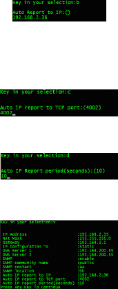
2-8. Type <b> to set Auto IP Report. Give the IP address of
the client PC to which the serial server has to give the
auto IP report.
2-9. Type <c> to set Auto IP report to TCP port. Give the
TCP Port No. of the client PC to which the serial server
has to give the auto IP report. By default its value is
4002.
2-10. Type <d> to set Auto IP report period <0-99 secs>.
By default its value is 10 secs.
2-11. Type <v> to view the settings, and then press
<Enter>.
2-12. Type <m> to go back to the previous menu, and then
press <Enter>. If any option in Network Settings
page was congured, telnet console will ask to save
Settings. Type <1> to save changes or type <0> to
quit without saving.
57
3. Serial settings
<< Main Menu >>
Type <3> and then press <Enter> on the Main Menu to
access serial settings screen.
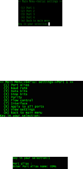
<< Main Menu -- >Serial settings >>
Type <1/2/3/.......> and then press <Enter> to set the serial
settings for the ports 1/2/3/..... respectively. The serial port
settings has the menu shown below:
<<Main Menu -- >Serial settings -- > Port 1/2/3......>>
3-1. Type <1> to set the Port Alias.
Note that Port Alias should not be more than 5
characters and no space should be allowed between
characters.
58
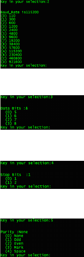
3-2. Type <2> to access the Baud rate screen, and type the
number to set Baud rate.
3-3. Type <3> to access the Data bits screen, and type the
number to set the Data bits.
3-4. Type <4> to access the Stop bits screen, and type the
number to set the Stop bits.
3-5. Type <5> to access the Parity screen, and type the
number to set the Parity.
59
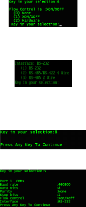
3-6. Type <6> to access Flow control screen, type the
number to set the Flow control.
3-7. Type <7> to display the Interface.
Note that this model supports only RS232/RS-422/RS-
485 Interface.
3-8. Type <8> to congure settings Apply to all ports.
3-9. Type <v> to view the settings of the Port.
3-10. Type <m> to go back to the previous menu. If any
option in Serial Port Settings page was congured,
60
telnet console will ask to save settings. Type <1> to
save changes or type <0> to quit without saving. Again
type <m> to go back to Main Menu.
4. Operating settings
<<Main Menu >>
Type <4> and then press <Enter> on the Main Menu to
access operating settings screen.
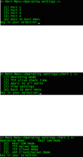
<<Main Menu -- >Operating settings >>
Type <1/2/3/.......> to set the operating settings for the
respective ports 1/2/3/....., and then press <Enter>.
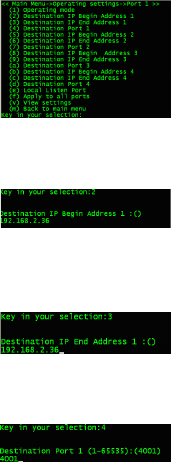
<<Main Menu -- >Operating settings -- > Port 1/2/3/.... >>
Type <1> to access the Operating mode of port, and type
number to set the operating mode.
61
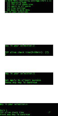
4-0. Real com mode
1. Real com mode is set with “0”…. Following screen
appears while entering into Real Com Mode.
By default, operating mode for all ports is Real Com
Mode.
2. Type <2> to set TCP Alive check time from the range
(0-99 min). By default its value is 7 mins.
3. Type <3> to congure settings apply to all ports.
4. Type <v> to view the settings made in Real Com mode
as below.
5. Type <m> to go back to the previous screen. If any
option in Operating Port Settings page was congured,
telnet console will ask to save settings. Type <1> to save
changes or Type <0> to quit without saving.
62
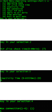
4-1. TCP server mode
1. Real com mode is set with “1”…. Following screen
appears while entering into TCP Server Mode.
2. Type <2> to set TCP Alive check time from the range (0-99
min). By default its value is 7 mins.
3. Type <3> to set Inactivity time from the range (0-65535
ms). By default its value is 0 ms.
4. Type <4> to set the Max connection from the range (1-4).
By default its value is 1.
Note that the Real Com Mode only 1 connection
per port is allowed at a time, for other modes max
connection setting applies.
63
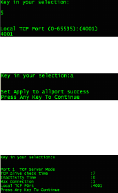
5. Type <5> to set the Local TCP Port. By default its value
is 4001.
6. Type <a> to congure settings apply to all ports.
7. Type <v> to view settings made in TCP Server Mode as
below.
8. Type <m> to go back to previous screen. If any option in
Operating Port Settings page was congured, Telnet
Console will ask to save settings. Type <1> to save
changes or type <0> to quit without saving.
64
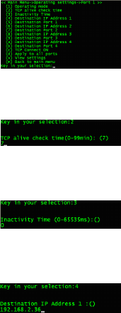
4-2 TCP Client Mode
1. Real com mode is set with “2”…. Following screen
appears while entering into TCP Server Mode.
2. Type <2> to set TCP Alive check time from the range
(0-99 min). By default its value is 7 mins.
3. Type <3> to set Inactivity time from the range (0-65535
ms). By default its value is 0 ms.
4. Type <4 / 6 / 8 / a> to set the Destination IP Address 1 /
2 / 3 / 4.
65
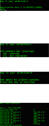
5. Type <5 / 7 / 9 / b> to set the Destination Port 1 / 2 / 3 /
4 from the range (0-65535). By default its value is 4001.
6. Type <c> to set the TCP Connect ON Mode. Type
<0> to select Start up mode or Type <1> to select Any
Character mode. By default the Connect ON Mode is
Start up.
7. Type <d> to congure settings apply to all ports.
8. Type <v> to view settings made in TCP Client Mode as
below.
9. Type <m> to go back to previous screen. If any option
in Operating Port Settings page was congured, telnet
console will ask to save settings. Type <1> to save
changes or type <0> to quit without saving.
66
4-3 UDP Client/Server Mode
1. Real com mode is set with “3”…. Following screen
appears while entering into UDP Client/Server Mode.
2. Type <2 / 5 / 8 / b> to set Destination IP End Address 1
/ 2 / 3 / 4.
3. Type <3 / 6 / 9 / c> to set Destination IP End Address 1
/ 2 / 3 / 4.
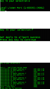
4. Type <4 / 7 / a / d> to set Destination Port 1 / 2 / 3 / 4
from the range (0-65535). By default its value is 4001.
67
5. Type <e> to set Local Listen Port from the range
(0-65535). By default its value is 4001.
6. Type <f> to congure settings apply to all ports.
7. Type <v> to view the settings made to UDP Client/
Server Mode as below.
8. Type <m> to go back to the previous screen. If any option
in Operating Port Settings page was congured, Telnet
Console will ask to save Settings. Type <1> to save
changes or Type <0> to quit without saving. Again type
<m> to go back to Main Menu.
68
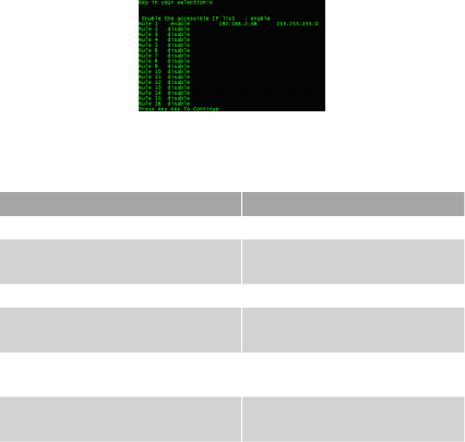
5. Accessible IP settings
<< Main Menu >>
Type <5> on the Main Menu, and then press <Enter> to
access Accessible IP settings page.
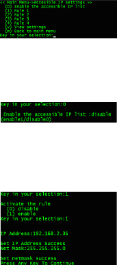
<<Main Menu -- >Accessible IP Settings >>
1. Type <0> to Enable Accessible IP List. Type <1> to
enable or type <0> to disable.
2. Type <1~g> to activate the rules 1~g. To activate the
rules, type 1 to enable or type <0> to disable. Then type
the IP address and Net Mask on each rule to allow the
authorised clients in order to access serial server.
69
3. Type <v> to view the settings made on Accessible IP
Settings page.
4. Refer the following table for more details about the
conguration example.
Allowable Hosts Input format
Any host Disable
192.168.2.246 192.168.2.246 /
255.255.255.255
192.168.2.1 to 192.168.2.254 192.168.2.0 / 255.255.255.0
192.168.0.1 to
192.168.255.254
192.168.0.0 / 255.255.0.0
192.168.2.1 to 192.168.2.128 192.168.2.0 /
255.255.255.128
192.168.2.129 to
192.168.2.254
192.168.2.128 /
255.255.255.128
5. Type <m> to go back to the previous menu. If any rule
in Accessible IP Settings page was congured, telnet
console will ask to save settings. Type <1> to save
changes or <0> quit without saving.
70
6. Auto warning settings
<< Main Menu >>
Type <6> on the Main Menu, and then press <Enter> to
access Auto warning settings page.
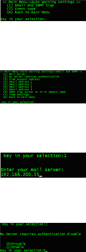
<< Main Menu -- >Auto warning settings>>
6-1 Email and SNMP trap
Type <1> to access Email and SNMP trap.
<< Main Menu -- >Auto warning settings -- >Email and
SNMP Trap >>
1. Type <1> to set the Mail server. Give the IP address of
the mail server.
2. Type <2> to set the My server requires authentication
screen, Enable if the mail server requires authentication
and set the user name and password. Disable if
authentication is not required.
71
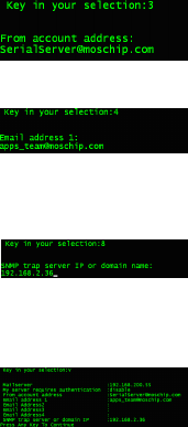
3. Type <3> to set From account address.
4. Type <4 / 5 / 6 /7> to set the Email address 1 / 2 / 3 / 4.
5. Type <8> to set the SNMP Trap server IP or domain
name.
6. Type <v> to view the settings made in Email and SNMP
strap page.
7. Type <m> to back to the previous menu. If any option
in Email and SNMP trap page was congured, telnet
console will ask to save settings. Type <1> to save
changes or type <0> to quit without saving.
72
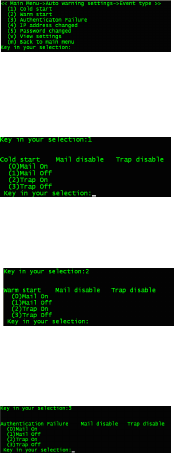
6-2 Event type
<< Main Menu -- >Auto warning settings >>
Type <2> to access Event type.
<< Main Menu -- >Auto warning setting -- >Event type >>
1. Type <1> to set the event Cold start. We can enable the
auto warning methods: Mail or Trap.
2. Type <2> to set the event Warm Start. We can enable
the auto warning methods: Mail or Trap.
3. Type <3> to set the event Authentication Failure. We
can enable the auto warning methods: Mail or Trap.
73
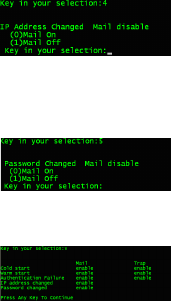
4. Type <4> to set the event IP Address Changed. We can
only enable the auto warning method: Mail.
5. Type <5> set the event Password Changed. We can
only enable the auto warning method: Mail.
6. Type <v> to view the settings made in Event Type page.
7. Type <m> to back to the Main Menu. If any option in
Event Type page was congured, telnet console will ask
to save settings. Type <1> to save changes or <0> quit
without saving.
74
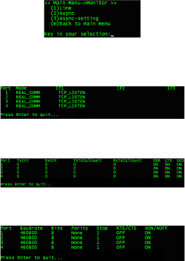
7. Monitor
<< Main Menu >>
Type <7> on the Main Menu, and then press <Enter> to
access Monitor settings page.
<< Main Menu -- >Monitor >>
1. Type <1> to monitor the Line status of serial server serial
ports, and then press <Enter> to quit.
2. Type <2> to monitor the Async status, and then press
<Enter> to quit.
3. Type <3> to monitor the Async-Setting status, and then
press <Enter> to quit.
4. Type <m> to go back to the Main Menu.
75
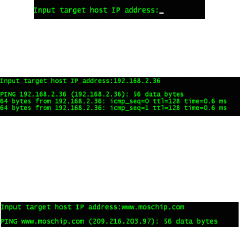
8. Ping
<< Main Menu >>
Type <8> on the Main Menu, and then press <Enter> to
access Ping settings page.
Give the Target Host IP address and press <Enter>. Type
<Ctrl-c> to stop the ping and to go back to Main Menu.
If the IP Address of DNS Server is given in Network
Settings page, then we can translate the Domain name
given in this ping option to IP address. See the screen
below.
76
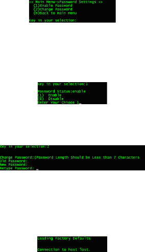
9. Change password
<< Main Menu >>
Type <9> on the Main Menu, and then press <Enter> to
access Password Settings page.
<< Main Menu -- > Password Settings>>
1. Type <1> to Enable password to the serial server. Type
<1> to Enable or type <0> to Disable the Password
Status.
2. Type <2> to Change the Password of the serial server.
Enter the Old Password. Then give the New Password
and then Re-enter New Password.
10. Load factory defaults
<< Main Menu >>
Type <a> on the Main Menu, and then press <Enter> to
access the Load factory Defaults settings page.

77
Regulatory compliance
FCC conditions
This equipment has been tested and found to comply with
Part 15 Class B of the FCC Rules. Operation is subject to
the following two conditions:
(1) This device may not cause harmful interference
(2) This device must accept any interference
received and include interference that may
cause undesired operation.
CE
This equipment is in compliance with the
requirements of the following regulations:
EN 55 022: CLASS B
WEEE information
For EU (European Union) member users: According to
the WEEE (Waste electrical and electronic equipment)
Directive, do not dispose of this product as household
waste or commercial waste. Waste electrical and electronic
equipment should be appropriately collected
and recycled as required by practices
established for your country. For information on
recycling of this product, please contact your
local authorities, your household waste disposal
service or the shop where you purchased the
product.

78
Specication
Item Description
Ports 4xRS-232/422/485
Connector 8-pin RJ-45
FIFO 512 bytes
ESD protect 15KV ESD, 3KV isolation (RS-485)
Transmission Speed 110bps~921.6Kbps
Interface GigaLAN / Wi-Fi
Interface connector RJ-45 / Antenna
Power requirements 5V3A DC / 9~36 VDC
Operating
temperature
0 ~ 55°C
Operating humidity 5 ~ 95% RH
Regulatory approvals FCC / CE

4-Port Wireless Serial Device Server
User's Manual
0110v1
FCC INFORMATION
This device complies with Part 15 of the FCC Rules. Operation is subject to the
following two conditions:
1. This device may not cause harmful interference, and 2. This device must
accept any interference received, including interference that may cause
undesired operation.
Note: This equipment has been tested and found to comply with the limits for a
Class B digital device, pursuant to part 15 of the FCC Rules. These limits are
designed to provide reasonable protection against harmful interference in a
residential installation. This equipment generates, uses and can radiate radio
frequency energy and, if not installed and used in accordance with the
instructions, may cause harmful interference to radio communications.
However, there is no guarantee that interference will not occur in a particular
installation. If this equipment does cause harmful interference to radio or
television reception, which can be determined by turning the equipment off and
on, the user is encouraged to try to correct the interference by one or more of
the following measures:
--Reorient or relocate the receiving antenna.
--Increase the separation between the equipment and receiver.
--Connect the equipment into an outlet on a circuit different from that to which
the receiver is connected.
--Consult the dealer or an experienced radio/TV technician for help.
Caution: Any changes or modifications not expressly approved by the party
responsible for compliance could void the user's authority to operate this
equipment.
RF Exposure: A distance of 20 cm shall be maintained between the antenna
and users, and the transmitter module may not be co-located with any other
transmitter or antenna.