Good Way Technology TD1000 Power Switch User Manual
Good Way Technology Co., Ltd. Power Switch
User manual
Power Switch
User’s Manual
ABOUT THIS MANUAL
This manual is designed for use with the Power Switch. Information in this document has
been carefully checked for accuracy; however, no guarantee is given to the correctness of the
contents. The information in this document is subject to change without notice. The manufacturer
does not make any representations or warranties (implied or otherwise) regarding the accuracy
and completeness of this document and shall in no event be liable for any loss of profit or any
commercial damage, including but not limited to special, incidental, consequential, or other
damage.
SAFETY INSTRUCTIONS
Always read the safety instructions carefully:
Keep this User’s Manual for future reference
Keep this equipment away from humidity
If any of the following situation arises, get the equipment checked by a service technician:
xThe equipment has been exposed to moisture.
xThe equipment has been dropped and damaged.
xThe equipment has obvious sign of breakage.
xThe equipment has not been working well or you cannot get it to work according to the
User’s Manual.
COPYRIGHT
This document contains proprietary information protected by copyright. All right are reserved. No
part of this manual may be reproduced by any mechanical, electronic or other means, in any
form, without prior written permission of the manufacturer.
TRADEMARKS
All trademarks and registered trademarks are the property of their respective owners or
companies.
i
Table of Contents
1. Introduction............................................................................................................1
Features..............................................................................................................2
Package Contents...............................................................................................2
LED Indicator ......................................................................................................2
Z-Wave.............................................................................................................2
Wireless Range ..................................................................................................3
2. Installation ..............................................................................................................4
Hardware Connection .........................................................................................4
Product Description.............................................................................................5
Installation Requirements ...................................................................................5
Installing the Power Switch................................................................................ 6
3. Specifications.........................................................................................................7
4. Regulatory Compliance.........................................................................................8
FCC Conditions ..................................................................................................8
WEEE Information ..............................................................................................8
ii
1. Introduction
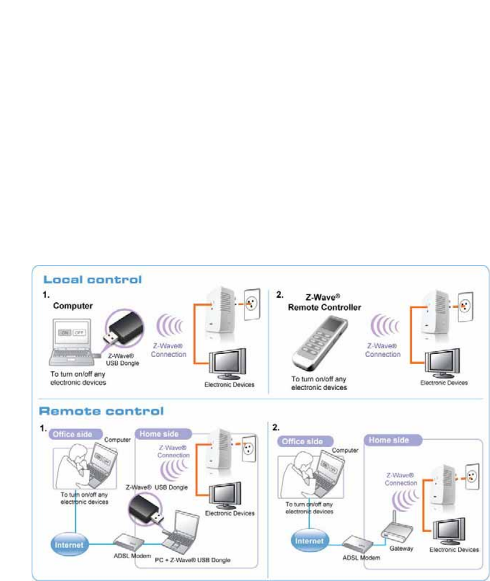
The Power Switch allows you to turn on/off the attached appliance, electronic
device or lamp wirelessly by using Z-Wave protocol remote control. You can
control the attached load in your home through PC connectivity with a Z-Wave
USB dongle when you are away from home.ʳʳʳʳ
ʳʳʳ Note: To avoid any dangerous accident, please don’t use this product on
the plug of extended power line or else instead of wall plug.
ʳʳ
ʳ
ʳ
ʳ
ʳ
1

Features
Simple plug and play installation.
Support electronic appliance or lamp with maximum loading of 1500W
Stand-by power consumption: 0.6 W
Control On/Off function manually with knob button or remote control by
PC equipped with Z-Wave certified USB dongle.
Fully compatible with Z-Wave enabled network and capable of
communicating with any Z-Wave certified device.
All products other then the Power Switch itself are sold separately.
Package Contents
Power Switch x1
User’s Manual x1
LED Indicator
LED Color Description
Power Red Power Switch Power on.
Link Green Z-Wave RF transfer or receive.
Z-Wave
Z-Wave is a state-of-the-art wireless technology used as a standard for
wireless home control. It is a next-generation wireless ecosystem that lets all
your home electronics talk to each other, and to you, via a controller or
gateway. It uses simple, reliable, low-power radio waves that easily travel
through walls, floors and cabinets. All products featuring the Z-Wave logo
are certified to work with one another.
2
3
Wireless Range
The Power Switch is made wireless by Z-Wave technology.
Typical range for a wireless module is approximately 100 feet. When installing
the module consider an open area with little obstruction for the best signal and
performance. Avoiding the obstruction between the module and controller
may make a negative effect on wireless performance and range.
2. Installation
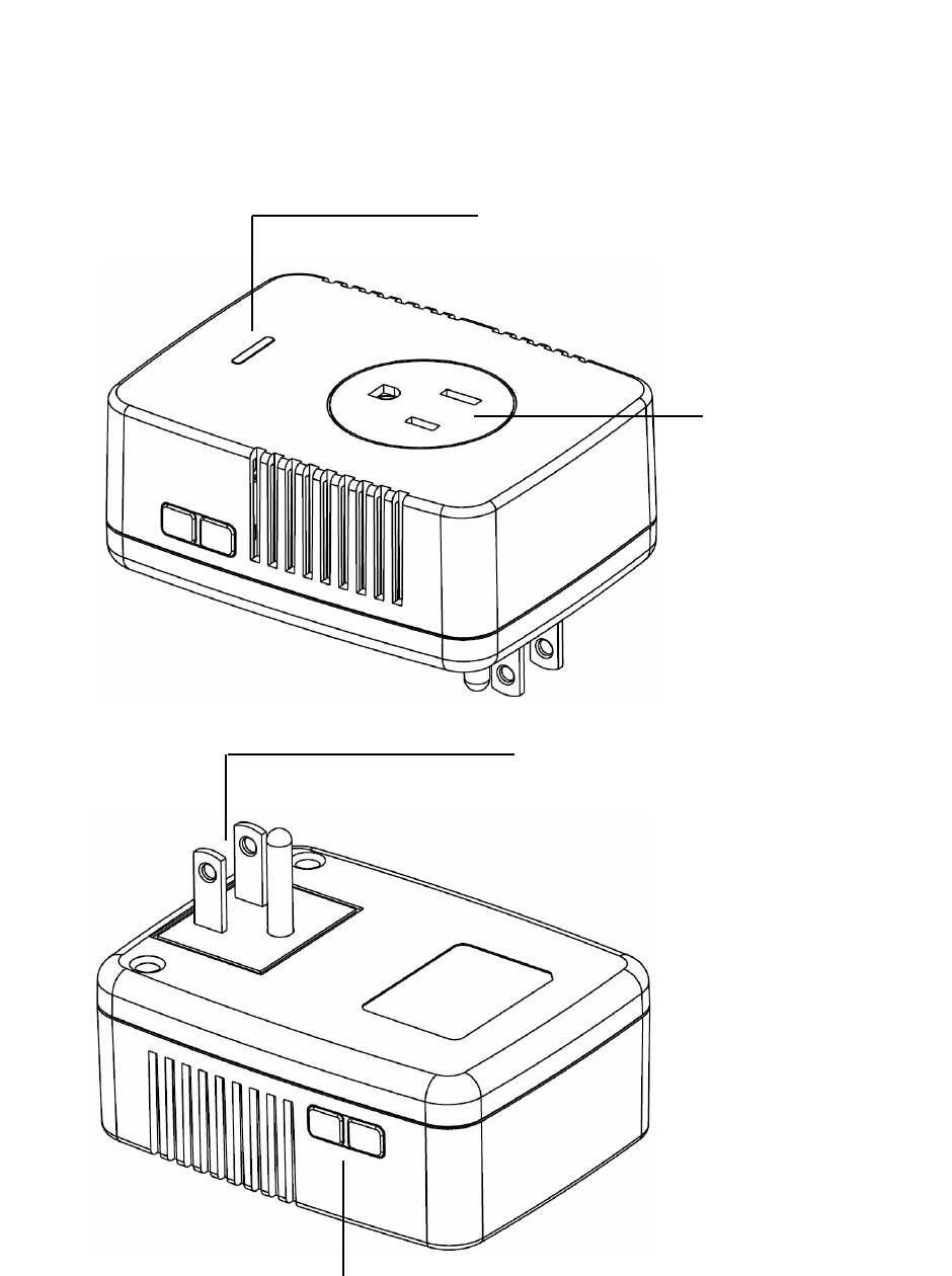
Hardware Connection
LED
Z-Wave Enabled
Outlet
Plug
Switch Button
4
Product Description
Below is a description of button, light and plugs for the Power Switch.
Z-Wave Enable Outlet
This outlet is a socket where the device or equipment you wish to control should
plug into, such as LCD monitor. Note that any device plugged into this outlet
must NOT exceed 1500 watts.
LED
The light will blink to indicate that the module has been entered “Program Mode”
or when it is communicating wirelessly to the Z-Wave controller (i.e. Z-Wave
Dongle).
Switch Button
When the Power Switch has been installed, pressing the switch button will
manually turn the attached device on or off.
When primary controller is waiting for inclusion or exclusion to setup Z-Wave
Network, please press this button could add or remove this device from Z-Wave
network.
Wall Outlet Plug
Located on the back of the Power Switch, the plug is used to plug your
module into an available wall outlet in your home or office.
Installation Requirements
To install this product you must have Z-Wave enabled controller, such as
Z-Wave Dongle, to make an association with Power Switch.
5
Installing the Power Switch
NOTE =======================================================
Before you install or use this Power Switch, please install your Z-Wave
controller first and make an inclusion for your Z-Wave device. Not all Z-Wave
enabled remote controls have the same installation process. Actual instructions
may vary; it depends on the software that Z-Wave controller provided.
============================================================
1. Please plug the Power Switch into an available wall outlet near
the load to be controlled in your desired location of your office or home.
2. Operate your control panel from Z-Wave controller to include the Power
Switch in your network.
3. Once the Power Switch has been included in your network, you may see
or get some information about your Power Switch on your control panel
or else to confirm that has been added. If not, try the process again or try
deleting this switch from Z-Wave controller first.
4. When the Power Switch has been added into Z-Wave control panel
successfully, you will need to configure it to a specific button or other else on
your control panel. Refer to your Z-Wave control panel for instructions on
how to do this.
5. Now you can plug your electric device into the Z-Wave enabled outlet on
the Power Switch and control your device on or off via your own PC.
6

7
3. Specifications
Item Description
Protocol Z-Wave (Binary Switch Command Class)
Frequency 908.42MHZ( US)
Transceiver Yes
Operating Voltage AC110~120V/60Hz
Max Loading 1500W
Stand-by power consumption 0.6 W
LED Indicator
Green :Z-Wave RF transfer or receive
Red : Power Switch power on
Switch On / Off (Side Knob Button)
Data Rate Up to 40 kbps
Operation Range Up to 100 feets
Application Indoor use
Working Environment
Operation temperature: 10 ~ 40 ̓C
Storage temperature: -10 ~ 80 ̓C
Dimensions (Lx W x H)
67.9mm x 89.3mm x 57mm,
(Included the height of wall outlet plug)
Housing Plastic PC 945
Flame Class UL 94 V-0
Compliance FCC, UL, Z-Wave
Specifications are subject to change without further notice

WEEE Information
For EU (European Union) member users:
According to the WEEE (Waste electrical and electronic equipment) Directive,
do not dispose of this product as household waste or commercial waste. Waste
electrical and electronic equipment should be appropriately collected and
recycled as required by practices established for your country. For information
on recycling of this product, please contact your local authorities, your
household waste disposal service or the shop where you purchased the product.
8
This equipment has been tested and found to comply with the limits for a Class B digital
device, pursuant to part 15 of the FCC rules. These limits are designed to provide reasonable
protection against harmful interference in a residential installation. This equipment generates,
uses and can radiate radio frequency energy and, if not installed and used in accordance with
the instructions, may cause harmful interference to radio communications. However, there is
no guarantee that interference will not
occur in a particular installation. If this equipment does cause harmful interference to radio or
television reception, which can determined by turning the equipment off and on, the user is
encouraged to try to correct the interference by one or more of the
following measures:
-Reorient or relocate the receiving antenna.
-Increase the separation between the equipment and receiver.
-Connect the equipment into an outlet on a circuit different from that to which the receiver is
connected.
-Consult the dealer or an experienced radio/TV technician for help.
You are cautioned that changes or modifications not expressly approved by the party
responsible for compliance could void your authority to operate the equipment.
This device complies with Part 15 of the FCC Rules. Operation is subject to the following two
conditions: (1) this device may not cause harmful interference and
(2) this device must accept any interference received, including interference that may cause
undesired operation
4. Regulatory Compliance