Good Way Technology TD11000Z2 Z-Wave Roller Shutter Controller User Manual
Good Way Technology Co., Ltd. Z-Wave Roller Shutter Controller
UserManual.wiki
>
Good Way Technology
>
TD11000Z2 User Manual
User Manual
Navigation menu
Upload a User Manual
Namespaces
Wiki Guide
HTML
PDF
Info
Views
User Manual
Discussion / Help
Navigation
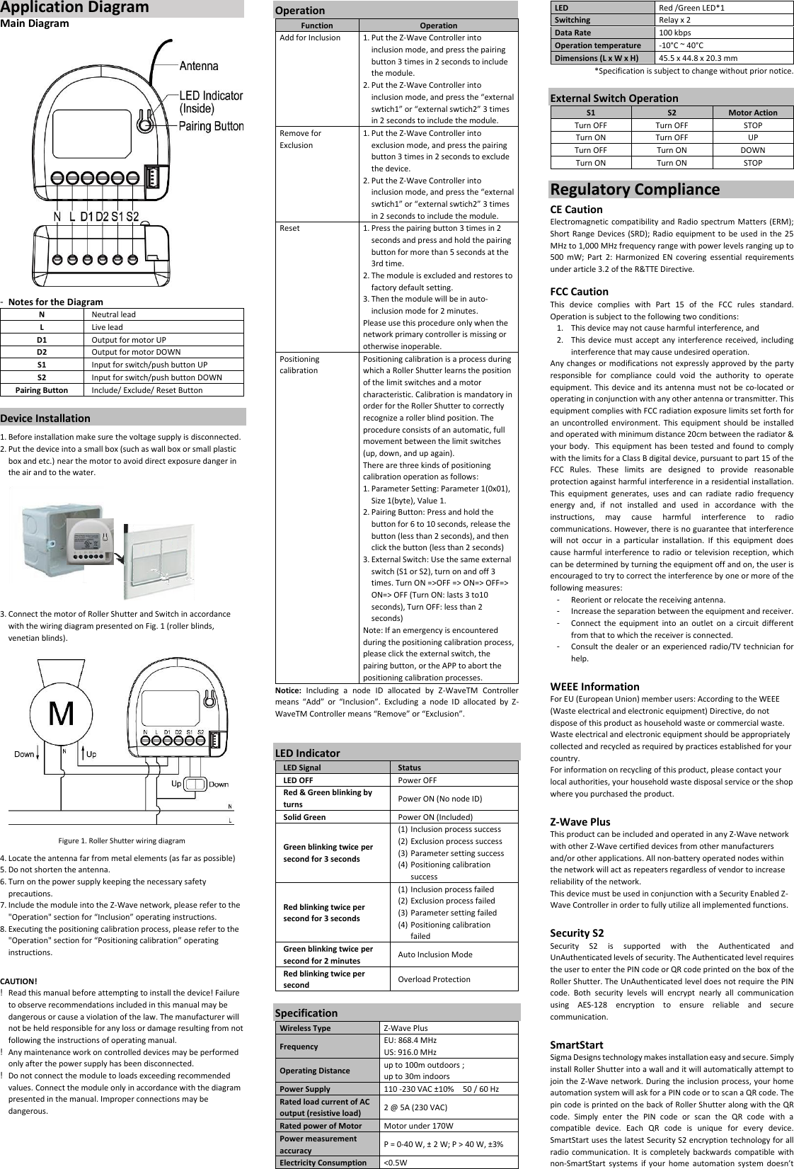
![User's Manual Introduction Z-Wave Roller Shutter Controller is an ideal for the remotely electric motor controller. It is used to control the motors of rollers, shades, blinds, venetian blinds and similar sun shade, which are single phase AC powered. The module can be controlled either through a Z-Wave network or through the wall switch, and measures power consumption of motor. Z-Wave Roller Shutter needs to motor calibration before use, please refer to CONFIGURATION command class parameter 0x01. Z-Wave Roller Shutter’s positioning calibration does not apply to motor without obstacle detection, using this function may cause unpredictable problems, please make sure your motor has obstacle detection function before positioning calibration. Package Contents ■ Z-Wave Roller Shutter Controller x1 ■ User Manual x1 Command Class Device Information GENERIC_TYPE_SWITCH_MULTILEVEL SPECIFIC_TYPE_CLASS_C_MOTOR_CONTROL z-wave protocol Command Class Node Info COMMAND_CLASS_ZWAVEPLUS_INFO_V2 COMMAND_CLASS_VERSION_V3 COMMAND_CLASS_MANUFACTURER_SPECIFIC_V2 COMMAND_CLASS_DEVICE_RESET_LOCALLY_V1 COMMAND_CLASS_POWERLEVEL_V1 COMMAND_CLASS_SWITCH_MULTILEVEL_V3 COMMAND_CLASS_CONFIGURATION_V1 COMMAND_CLASS_ASSOCIATION_V2 COMMAND_CLASS_ASSOCIATION_GRP_INFO_V1 COMMAND_CLASS_SWITCH_BINARY_V1 COMMAND_CLASS_METER_V3 COMMAND_CLASS_FIRMWARE_UPDATE_MD_V4 COMMAND_CLASS_SUPERVISION_V1 COMMAND_CLASS_Transport_Service_V2 COMMAND_CLASS_SECURITY_V1 COMMAND_CLASS_SECURITY_2_V1 The Below listed Command Class are all supported the Security S2 COMMAND_CLASS_VERSION_V3 COMMAND_CLASS_MANUFACTURER_SPECIFIC_V2 COMMAND_CLASS_DEVICE_RESET_LOCALLY_V1 COMMAND_CLASS_POWERLEVEL_V1 COMMAND_CLASS_SWITCH_MULTILEVEL_V3 COMMAND_CLASS_CONFIGURATION_V1 COMMAND_CLASS_ASSOCIATION_V2 COMMAND_CLASS_ASSOCIATION_GRP_INFO_V1 COMMAND_CLASS_SWITCH_BINARY_V1 COMMAND_CLASS_METER_V3 COMMAND_CLASS_FIRMWARE_UPDATE_MD_V4 COMMAND_CLASS_SUPERVISION_V1 Detailed description of each command class 【ZWAVEPLUS INFO command class】 The Z-Wave Plus Info Get Command is used to get additional information of the Z-Wave Plus device in question. 【VERSION command class】 The user can enquire the version of the unit using VERSION_GET command. It will return VERSION_REPORT Command. Version Report Command: [Command Class Version, Version Report, Z-Wave Library Type, Z-Wave Protocol Version, Z-Wave Protocol Sub Version, Application Version, Application Sub Version] 【MANUFACTURER SPECIFIC command class】 The user can use the Manufacturer Specific Get Command to request manufacturer specific information from another node. Manufacturer Specific Report Command: [Command Class Manufacturer Specific, Manufacturer ID 1, Manufacturer ID 2, Product Type ID 1, Product Type ID 2, Product ID 1, Product ID 2] 【DEVICE RESET LOCALLY command class】 The Device Reset Locally Command Class is used to notify central controllers that a Z-Wave device is resetting its network specific parameters. 【POWERLEVEL command class】 The Power level Command Class defines RF transmit power controlling commands useful when installing or testing a network. The commands make it possible for supporting controllers to set/get the RF transmit power level of a node and test specific links between nodes with a specific RF transmit power level. 【BASIC command class】 Control the roller shutter to be opened or closed after receiving the BASIC_SET command. To be opened: [Command Class Multilevel, Multilevel Set, Value = 0xFF] To be closed: [Command Class Multilevel, Multilevel Set, Value= 0x00] To be the percentage of full opened position: [Command Class Multilevel, Multilevel Set, Value = 0x01~0x63] 【SWITCH MULTILEVEL command class】 Control the roller shutter to be opened, closed, stopped or be the percentage of full opened position after receiving the SWITCH MULTILEVEL command. To be opened: [Command Class Multilevel, Multilevel Set, Value = 0xFF] To be closed: [Command Class Multilevel, Multilevel Set, Value= 0x00] To be the percentage of full opened position: [Command Class Multilevel, Multilevel Set, Value = 0x01~0x63] To be stopped: [Command Class Multilevel, SWITCH_MULTILEVEL_STOP_LEVEL_CHANGE] 【CONFIGURATION command class】 This class is used for setting certain vendor specific configuration variables. See the following table for configuration variables: Parameter Name Size (byte) Range Default value Description 1 (0x01) Positioning Calibration 1 0 - 1 0 0: Disable 1: Executing calibration 2 (0x02) External switch Protection 1 0 - 1 0 0: Enable external switch 1: Disable external switch 3 (0x03) When the door is opened, set the delay time for automatic closing. 2 0 - 32767 0 0: Disable automatic closing 1 - 32767: The door will be closed automatically in 1 - 32767sec 4 (0x04) When the door is open, set the delay time for automatic notification. 2 0 - 32767 0 0: Disable automatic notification 1 - 32767: The notification will be sent automatically in 1 - 32767sec 5 (0x05) Set the operation mode 1 0 - 1 0 0: Roller Shutter 1: Venetian (up/down and slate rotation) 6 (0x06) Set the angle of blinds 1 0 - 6 0 Angles of blinds 0:0∘ 1:30∘ 2:60∘ 3:90∘ 4:120∘ 5:150∘ 6:180∘ 7 (0x07) Set the slats turning time 1 0 - 127 15 (1.5sec) 0:Disable. 1 - 127: 0.1 - 12.7 sec 8 (0x08) Set the delay time to start the motor up to the blade 1 0 - 127 0 0:No offset time 1 - 127: 0.1 - 12.7 sec 9 (0x09) Set the delay time to start the motor down to the blade 1 0 - 127 0 0:No offset time 1 - 127: 0.1 – 12.7 sec 10 Set the 1 0 - 100 0 0:Disabled (0x0A) power changed percentage to send the power report 1 - 100: 1% - 100% 11 (0x0B) Set the time interval of reporting watts in seconds 2 0, 60 - 32767 300 sec 0:Disable 60 - 32767: 60 - 32767sec 12 (0x0C) Set the time interval of reporting KWH in seconds 2 0, 60 - 32767 3600 0:Disable 60 - 32767: 60 - 32767sec 【ASSOCIATION command class】 The device can be set 1 auto-report ID in Group 1. The device sends an unsolicited command to the configured destinations when triggered by an event. Group1:"Lifeline" : 【ASSOCIATION GRP INFO command class】 The purpose of the Association Group Information (AGI) Command Class is to allow a device to report the capabilities of each association group supported by the device. 【SWITCH_BINARY command class】 Control the roller shutter to be opened or closed after receiving the SWITCH BINARY command. To be opened: [Command Class SWITCH_BINARY, Set Value = 0xFF] To be closed: [Command Class SWITCH_BINARY, Set Value = 0x00] 【METER command class】 The Meter Command Class is intended for Z-Wave enabled devices capable of reporting energy measurements in addition to any main functionality or features e.g. an appliance module reporting the current consumption of the connected load. The Meter command class not support V1&V2 version. And it will take about 3 seconds to show the meter report on the request sending device. 【FIRMWARE UPDATE META DATA command class】 Support OTA (On-The-Air) firmware update function. 【COMMAND_CLASS_SECURITY_V1】 【COMMAND_CLASS_SECURITY_2_V1】 This device is a security enabled Z-Wave Plus product that is able to use encrypted Z-Wave Plus messages to communicate to other security enabled Z-Wave Plus products. Product Overview Product Dimensions](https://usermanual.wiki/Good-Way-Technology/TD11000Z2/User-Guide-3966014-Page-1.png)