Good Way Technology TD13000Z2 Z-Wave In-Wall Power Monitor Switch User Manual
Good Way Technology Co., Ltd. Z-Wave In-Wall Power Monitor Switch
UserManual.wiki
>
Good Way Technology
>
TD13000Z2 User Manual
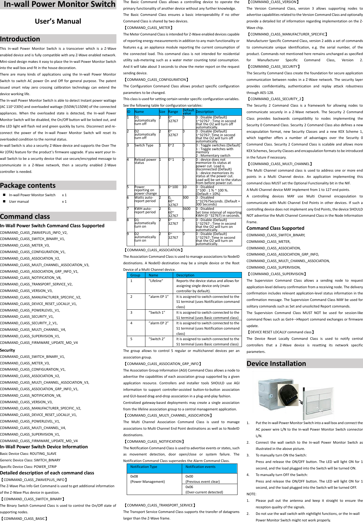
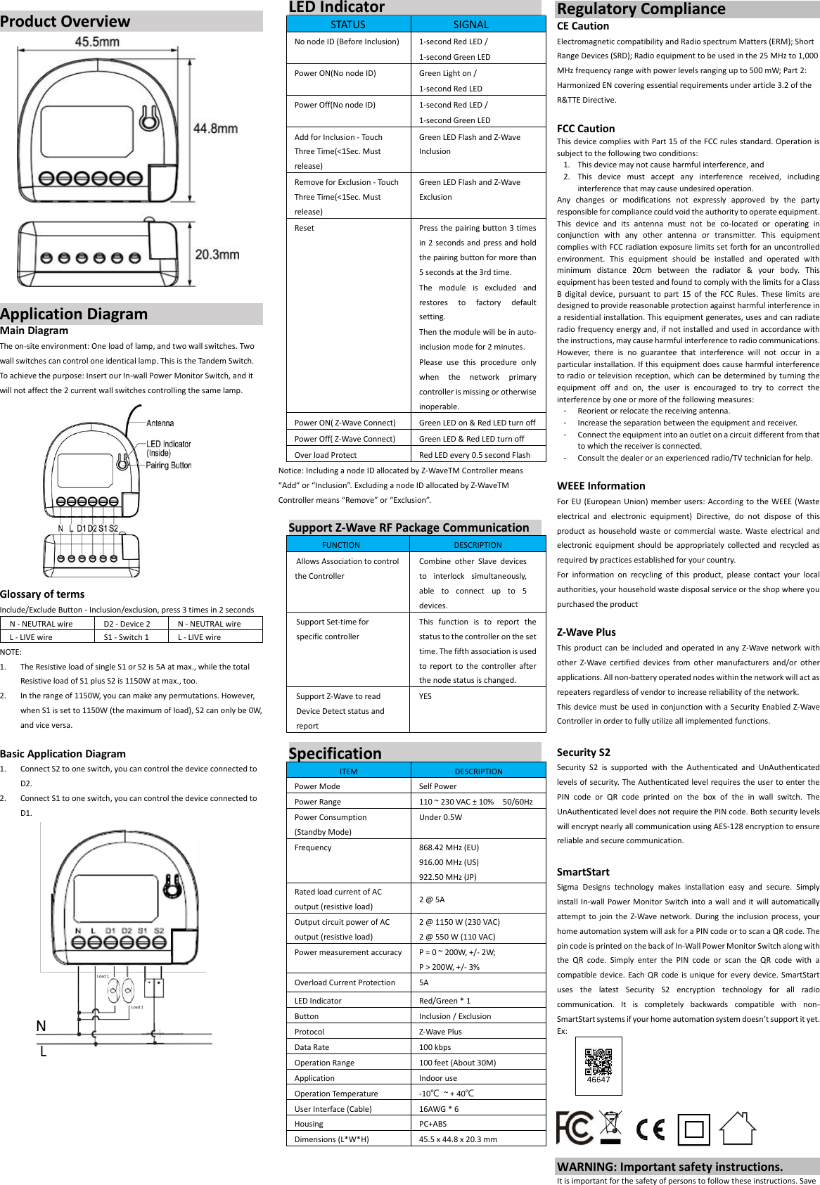
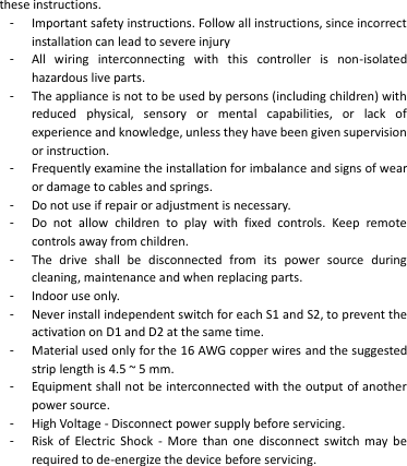
User Manual
Navigation menu
Upload a User Manual
Namespaces
Wiki Guide
HTML
PDF
Info
Views
User Manual
Discussion / Help
Navigation