Goodman Mfg Gpg13 Users Manual
GPG13 to the manual 08f66362-d64c-446f-88b9-cf19b5583914
2015-02-02
: Goodman-Mfg Goodman-Mfg-Gpg13-Users-Manual-429708 goodman-mfg-gpg13-users-manual-429708 goodman-mfg pdf
Open the PDF directly: View PDF ![]() .
.
Page Count: 40
Affix this manual and Users Information Manual adjacent to the unit.
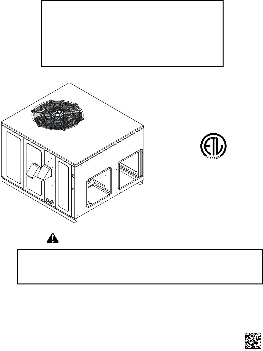
INSTALLATION & OPERATING
INSTRUCTIONS for
GPG13
SINGLE PACKAGE GAS-ELECTRIC
HEATING & COOLING UNIT
CUS
®
Goodman Manufacturing Company, L.P.
IO-288B 5151 San Felipe, Suite 500, Houston, TX 77056
07/08 www.goodmanmfg.com
© 2005 - 2008 Goodman Manufacturing Company, L.P.
*NOTE: Please contact your distributor or our
website for the applicable product data
book referred to in this manual.
This Forced Air Central Unit Design Complies With
Requirements Embodied in The American National
Standard / National Standard of Canada Shown Below.
ANSI Z21.47•CSA-2.3 Central Furnaces
RECOGNIZE THIS SYMBOL AS A SAFETY PRECAUTION.
ATTENTION INSTALLING PERSONNEL
Prior to installation, thoroughly familiarize yourself with this Installation Manual. Observe all safety warnings. During
installation or repair, caution is to be observed.
It is your responsibility to install the product safely and to educate the customer on its safe use.
These installation instructions cover the outdoor
installation of single package gas electric heating and
cooling units. See the Product Data Book applicable to
your model* for information regarding accessories.
2
INDEX
Replacement Parts ............................................................................................................................................................. 3
ORDERING PARTS .............................................................................................................................................. 3
Safety Instructions ............................................................................................................................................................. 3
Unit location........................................................................................................................................................................ 4
ALL INSTALLATIONS:........................................................................................................................................... 4
GROUND LEVEL INSTALLATIONS ONLY: .................................................................................................................. 4
ROOFTOP INSTALLATIONS ONLY:........................................................................................................................... 4
ROOF CURB INSTALLATIONS ONLY:....................................................................................................................... 5
General Information ........................................................................................................................................................... 5
TRANSPORTATION DAMAGE ................................................................................................................................... 6
Rigging Details ................................................................................................................................................................... 6
Gas piping ........................................................................................................................................................................... 6
HIGH ALTITUDE DERATE (U.S. INSTALLATIONS ONLY) ............................................................................................... 6
PIPING ............................................................................................................................................................. 6
GAS PIPING CHECKS.......................................................................................................................................... 7
Propane Gas Installations .................................................................................................................................................. 7
TANKS AND PIPING ............................................................................................................................................. 8
Electrical Wiring ................................................................................................................................................................. 8
THERMOSTAT LOCATION ....................................................................................................................................... 8
UNIT VOLTAGE ................................................................................................................................................... 9
HEAT A NTICIPATOR SETTING .................................................................................................................................. 9
Circulating Air and Filters ................................................................................................................................................ 10
AIRFLOW CONVERSION ...................................................................................................................................... 10
DUCTWORK ...................................................................................................................................................... 10
FILTERS .......................................................................................................................................................... 10
Venting ...............................................................................................................................................................................11
FLUE HOOD INSTALLATION ...................................................................................................................................11
Condensate Drain ..............................................................................................................................................................11
CONDENSATE DRAIN CONNECTION ........................................................................................................................11
Normal sequences of operation .......................................................................................................................................11
HEATING ..........................................................................................................................................................11
COOLING .........................................................................................................................................................11
FAN ONLY ...................................................................................................................................................... 12
Startup, Adjustments, and Checks .................................................................................................................................. 12
HEATING STARTUP ............................................................................................................................................ 12
COOLING STARTUP ........................................................................................................................................... 15
Troubleshooting ................................................................................................................................................................ 15
IGNITION CONTROL ERROR CODES ...................................................................................................................... 15
ABNORMAL OPERATION - HEATING .................................................................................................................... 16
ABNORMAL OPERATION - COOLING ................................................................................................................... 16
Maintenance ..................................................................................................................................................................... 17
FILTER REPLACEMENT OR CLEANING .................................................................................................................... 17
CABINET FINISH MAINTENANCE ........................................................................................................................... 17
CLEAN OUTSIDE COIL (QUALIFIED SERVICER ONLY) ............................................................................................. 17
CONDENSER, EVAPORATOR, AND INDUCED DRAFT MOTORS ..................................................................................... 17
FLAME SENSOR (QUALIFIED SERVICER ONLY) ...................................................................................................... 17
FLUE PASSAGES (QUALIFIED SERVICER ONLY) ..................................................................................................... 17
CLEANING FLUE PASSAGES (QUALIFIED SERVICER ONLY) ...................................................................................... 17
MAIN BURNER FLAME (QUALIFIED SERVICER ONLY).............................................................................................. 18
CLEANING BURNERS ......................................................................................................................................... 18
Accessories and Functional Parts ................................................................................................................................... 18
SHEET METAL ACCESSORIES .............................................................................................................................. 18
FUNCTIONAL PARTS .......................................................................................................................................... 18
GENERAL INFORMATION ..................................................................................................................................... 18
Ignition Control Diagnostic Indicator Chart .................................................................................................................... 19
Heating Timing Chart ....................................................................................................................................................... 19
Cooling Timing Chart ....................................................................................................................................................... 19
APPENDIX ......................................................................................................................................................................... 20
Wiring Diagrams .......................................................................................................................................................... 21-36
Minimum Clearances ....................................................................................................................................................... 37
Recommended Filter Sizes ............................................................................................................................................. 37
3
REPLACEMENT PARTS
ORDERING P ARTS
When reporting shortages or damages, or ordering repair
parts, give the complete unit model and serial numbers as
stamped on the unit’s nameplate.
Replacement parts for this appliance are available through your
contractor or local distributor. For the location of your nearest
distributor, consult the white business pages, the yellow page
section of the local telephone book or contact:
SERVICE PARTS DEPARTMENT
GOODMAN MANUFACTURING COMPANY, L.P.
5151 SAN FELIPE, SUITE 500
HOUSTON, TEXAS 77056
(713) 861 – 2500
SAFETY INSTRUCTIONS
TO THE INSTALLER
Before installing this unit, please read this manual to
familiarize yourself on the specific items which must be
adhered to, including maximum external static pressure to
unit, air temperature rise, minimum or maximum CFM and
motor speed connections.
TO THE OWNER
A warranty certificate is provided with the unit. Read the
warranty carefully and note what is covered. Keep the warranty
certificate in a safe place so you can find it when necessary.
Keep this literature in a safe place for future reference.
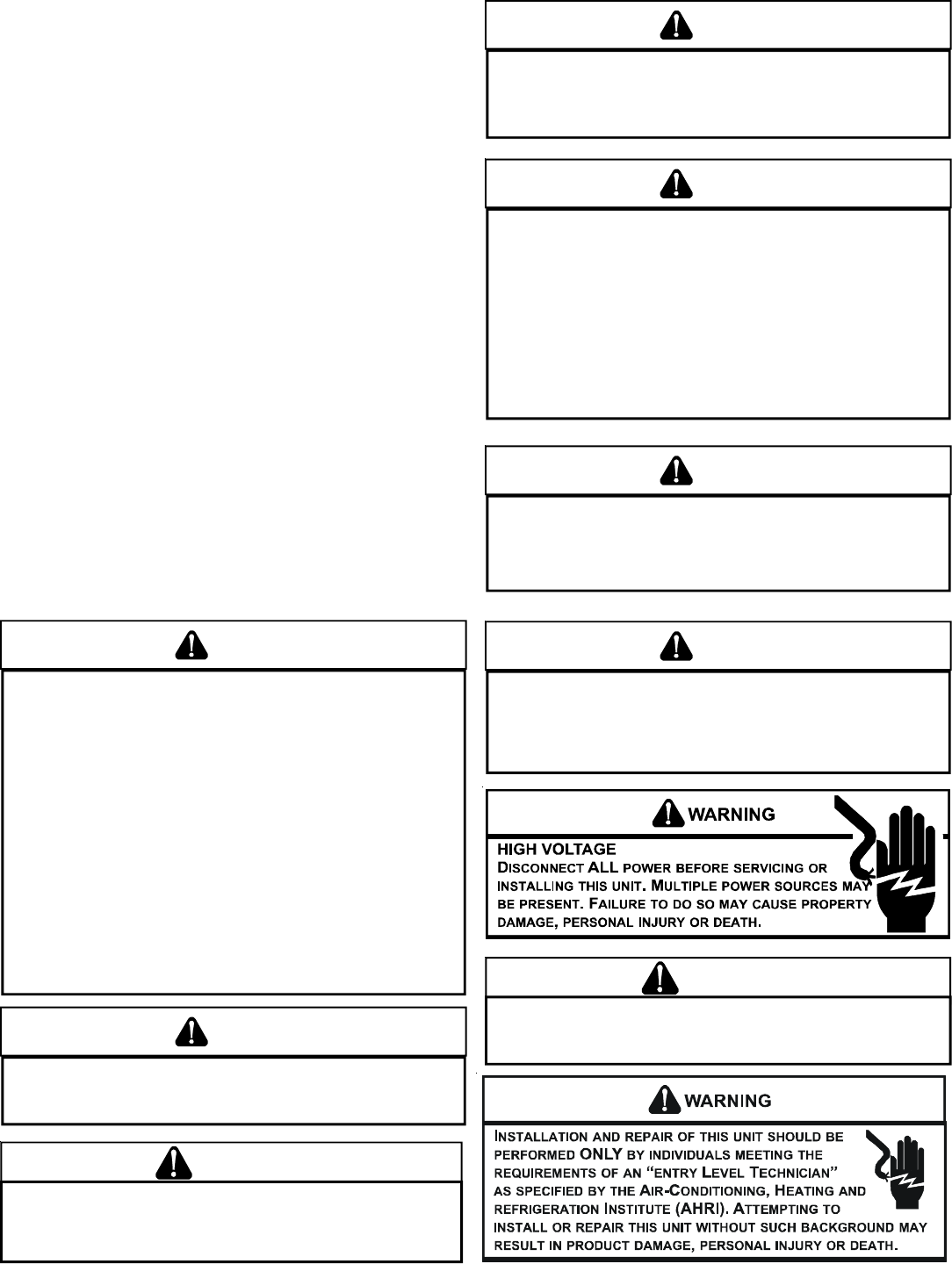
WARNING
IF THE INFORMATION IN THESE INSTRUCTIONS IS NOT FOLLOWED EXACTLY, A
FIRE OR EXPLOSION MAY RESULT CAUSING PROPERTY DAMAGE, PERSONAL
INJURY OR LOSS OF LIFE.
– DO NOT STORE OR USE GASOLINE OR OTHER FLAMMABLE VAPORS AND
LIQUIDS IN THE VICINITY OF THIS OR ANY OTHER APPLIANCE.
– WHAT TO DO IF YOU SMELL GAS:
•
DO NOT TRY TO LIGHT ANY APPLIANCE.
•
DO NOT TOUCH ANY ELECTRICAL SWITCH; DO NOT USE ANY
PHONE IN YOUR BUILDING.
•
IMMEDIATELY CALL YOUR GAS SUPPLIER FROM A NEIGHBOR’S
PHONE.
FOLLOW THE GAS SUPPLIER’S INSTRUCTIONS.
•
IF YOU CANNOT REACH YOUR GAS SUPPLIER, CALL THE FIRE
DEPARTMENT.
–
INSTALLATION AND SERVICE MUST BE PERFORMED BY A QUALIFIED INSTALLER,
SERVICE AGENCY OR THE GAS SUPPLIER.
WARNING
SHOULD OVERHEATING OCCUR OR THE GAS SUPPLY FAIL TO SHUT OFF, TURN
OFF THE MANUAL GAS SHUTOFF VALVE EXTERNAL TO THE FURNACE BEFORE
TURNING OFF THE ELECTRICAL SUPPLY.
WARNING
THIS PRODUCT CONTAINS OR PRODUCES A CHEMICAL OR CHEMICALS WHICH
MAY CAUSE SERIOUS ILLNESS OR DEATH AND WHICH ARE KNOWN TO THE
STATE OF CALIFORNIA TO CAUSE CANCER, BIRTH DEFECTS OR OTHER
REPRODUCTIVE HARM.
WARNING
HEATING UNIT SHOULD NOT BE UTILIZED WITHOUT REASONABLE, ROUTINE,
INSPECTION, MAINTENANCE AND SUPERVISION. IF THE BUILIDNG IN WHICH ANY
SUCH DEVICE IS LOCATED WILL BE VACANT, CARE SHOULD BE TAKEN THAT
SUCH DEVICE IS ROUTINELY INSPECTED, MAINTAINED AND MONITORED. IN THE
EVENT THAT THE BUILDING MAYBE EXPOSED TO FREEZING TEMPERATURES
AND WILL BE VACANT, ALL WATER-BEARING PIPES SHOULD BE DRAINED, THE
BUILDING SHOULD BE PROPERLY WINTERIZED, AND THE WATER SOURCE
CLOSED. IN THE EVENT THAT THE BUILDING MAY BE EXPOSED TO FREEZING
TEMPERATURES AND WILL BE VACANT, ANY HYDRONIC COIL UNITS SHOULD
BE DRAINED AS WELL AND, IN SUCH CASE, ALTERNATIVE HEAT SOURCES
SHOULD BE UTILIZED.
WARNING
TO AVOID PROPERTY DAMAGE, PERSONAL INJURY OR DEATH, DO NOT USE
THIS UNIT IF ANY PART HAS BEEN UNDER WATER. IMMEDIATELY CALL A
QUALIFIED SERVICE TECHNICIAN TO INSPECT THE FURNACE AND TO REPLACE
ANY PART OF THE CONTROL SYSTEM AND ANY GAS CONTROL HAVING BEEN
UNDER WATER.
WARNING
THIS UNIT MUST NOT BE USED AS A "CONSTRUCTION HEATER" DURING THE
FINISHING PHASES OF CONSTRUCTION ON A NEW STRUCTURE. THIS TYPE OF
USE MAY RESULT IN PREMATURE FAILURE OF THE UNIT DUE TO EXTREMELY
LOW RETURN AIR TERMPERATURES AND EXPOSURE TO CORROSIVE OR VERY
DIRTY ATMOSPHERES.
WARNING
TO PREVENT THE RISK OF PROPERTY DAMAGE, PERSONAL INJURY, OR DEATH,
DO NOT STORE COMBUSTIBLE MATERIALS OR USE GASOLINE OR OTHER
FLAMMABLE LIQUIDS OR VAPORS IN THE VICINITY OF THIS APPLIANCE.
WARNING
DO NOT CONNECT TO OR USE ANY DEVICE THAT IS NOT DESIGN CERTIFIED
BY GOODMAN FOR USE WITH THIS UNIT. SERIOUS PROPERTY DAMAGE,
PERSONAL INJURY, REDUCED UNIT PERFORMANCE AND/OR HAZARDOUS
CONDITIONS MAY RESULT FROM THE USE OF SUCH NON-APPROVED DEVICES.
4
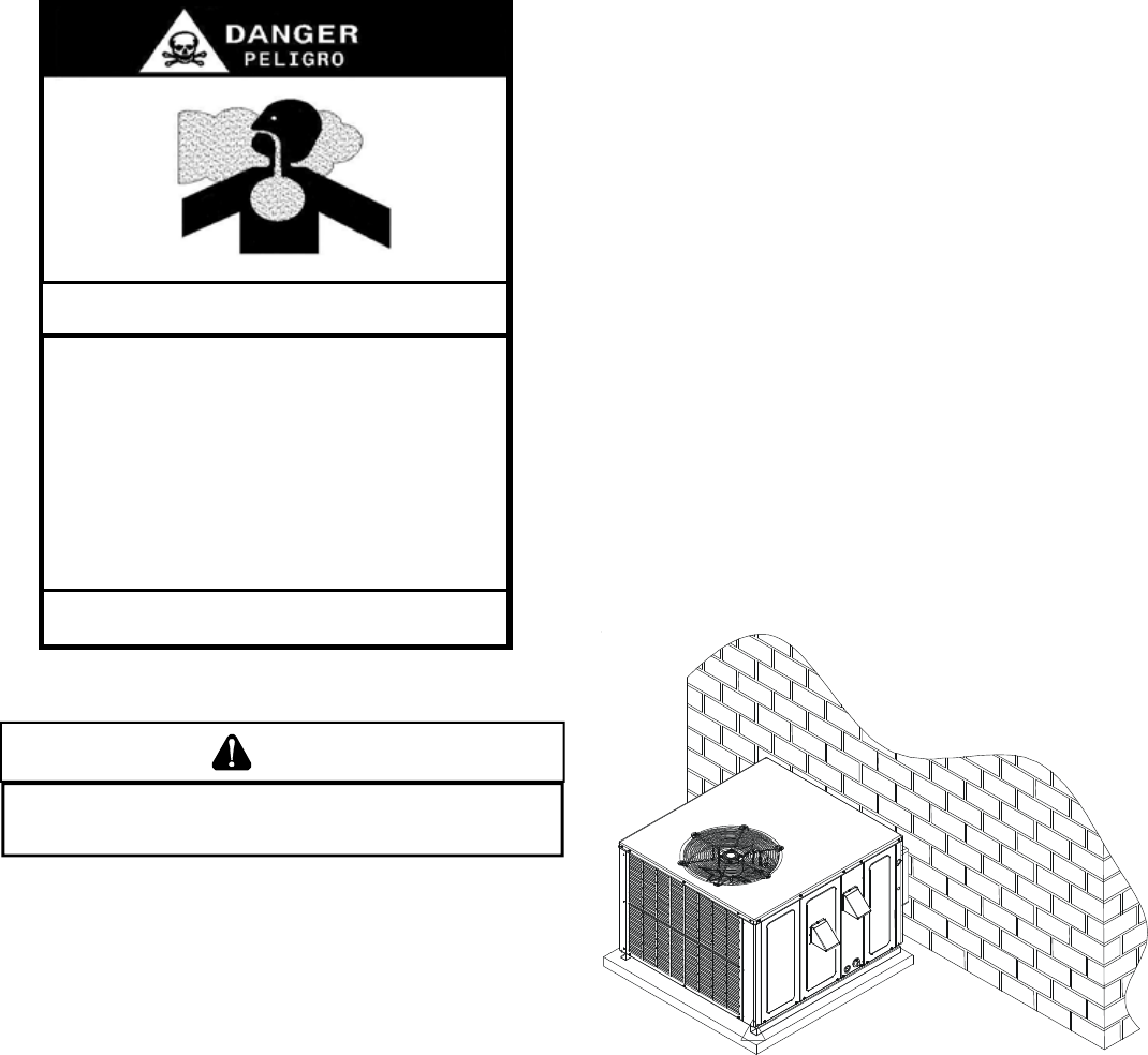
CARBON
MONOXIDE
POISONING
HAZARD
B10259-216
Carbon monoxide producing devices (such as an automobile, space
heater, gas water heater, etc.) should not be operated in enclosed areas
such as unventilated garages, utility rooms or parking areas because of
the danger of carbon monoxide (CO) poisoning resulting from the exhaust
emissions. If a furnace or air handler is installed in an enclosed area such
as a garage, utility room or parking area and a carbon monoxide producing
device is operated therein, there must be adequate, direct outside
ventilation.
This ventilation is necessary to avoid the danger of CO poisoning which
can occur if a carbon monoxide producing device continues to operate in
the enclosed area. Carbon monoxide emissions can be (re)circulated
throughout the structure if the furnace or air handler is operating in any
mode.
CO can cause serious illness including permanent brain damage or death.
Special Warning for Installation of Furnaces or Air Handling Units in
Enclosed Areas such as Garages, Utility Rooms or Parking Areas
UNIT LOCATION
WARNING
TO PREVENT POSSIBLE EQUIPMENT DAMAGE, PROPERTY DAMAGE, PERSONAL
INJURY OR DEATH, THE FOLLOWING BULLET POINTS MUST BE OBSERVED
WHEN INSTALLING THE UNIT.
IMPORTANT NOTE: Remove wood shipping rails prior to instal-
lation of the unit.
ALL INSTALLATIONS:
•For proper flame pattern within the heat exchanger and
proper condensate drainage, the unit must be mounted
level.
•The flue outlet hood must be at least 12 inches from any
opening through which flue gases could enter a building,
and at least three feet above any forced air inlet located
within ten feet. The economizer/manual fresh air intake/
motorized fresh air intake and combustion air inlet
mounted on the unit are not affected by this restriction.
•To avoid possible corrosion of the heat exchanger, do not
locate the unit in an area where the outdoor air (i.e.
combustion air for the unit) will be frequently contaminated
by compounds containing chlorine or fluorine. Common
sources of such compounds include swimming pool
chemicals and chlorine bleaches, paint stripper,
adhesives, paints, varnishes, sealers, waxes (which are
not yet dried) and solvents used during construction and
remodeling. Various commercial and industrial processes
may also be sources of chlorine/fluorine compounds.
•To avoid possible illness or death of the building occupants,
do NOT locate outside air intake device (economizer,
manual fresh air intake, motorized fresh air intake) too close
to an exhaust outlet, gas vent termination, or plumbing vent
outlet. For specific distances required, consult local codes.
•Allow minimum clearances from the enclosure for fire
protection, proper operation, and service access (see
appendix). These clearances must be permanently
maintained.
•The combustion air inlet and flue outlet hoods on the unit
must never be obstructed. If used, do not allow the
economizer/manual fresh air damper/ motorized fresh air
damper to become blocked by snow or debris. In some
climates or locations, it may be necessary to elevate the
unit to avoid these problems.
•When the unit is heating, the temperature of the return air
entering the unit must be between 50° F and 100° F.
GROUND L EVEL I NSTALLATIONS O NLY:
•When the unit is installed on the ground adjacent to the
building, a level concrete (or equal) base is recommended.
Prepare a base that is 3” larger than the package unit
footprint and a minimum of 3” thick.
•The base should also be located where no runoff of water
from higher ground can collect in the unit.
Outside Slab Installation
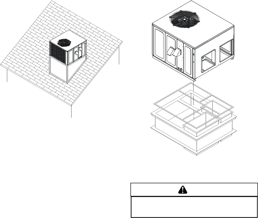
ROOFTOP INSTALLATIONS O NLY:
NOTE: To ensure proper condensate drainage, unit must be
installed in a level position.
•To avoid possible property damage or personal injury, the
roof must have sufficient structural strength to carry the
weight of the unit(s) and snow or water loads as required
by local codes. Consult a structural engineer to determine
the weight capabilities of the roof.
5
Rooftop Installation
•The unit may be installed directly on wood floors or on
Class A, Class B, or Class C roof covering material.
•To avoid possible personal injury, a safe, flat surface for
service personnel should be provided.
ROOF CURB INSTALLATIONS ONLY:
•Sufficient structural support must be determined prior to
locating and mounting the curb and package unit.
•Ductwork must be constructed using industry guidelines.
The duct work must be placed into the roof curb before
mounting the package unit.
•Curb insulation, cant strips, flashing and general roofing
material are furnished by the contractor.
Roof Curb Installation
GENERAL INFORMATION
WARNING
TO PREVENT PROPERTY DAMAGE, PERSONAL INJURY OR DEATH, DUE TO FIRE,
EXPLOSIONS, SMOKE, SOOT, CONDENSATION, ELECTRIC SHOCK OR CARBON
MONOXIDE, THIS UNIT MUST BE PROPERLY INSTALLED, REPAIRED, OPERATED,
AND MAINTAINED.
This unit is approved for outdoor installation ONLY. To assure
that your unit operates safely and efficiently, it must be installed,
operated, and maintained in accordance with these installation and
operating instructions, all local building codes and ordinances, or in
their absence, with the latest edition of the National Fuel Gas Code
NFPA54/ANSI Z223.1 and National Standard of Canada CAN/CSA
B149 Installation Codes.
The heating and cooling capacities of the unit should be greater
than or equal to the design heating and cooling loads of the area to
be conditioned. The loads should be calculated by an approved
method or in accordance with A.S.H.R.A.E. Guide or Manual J -
Load Calculations published by the Air Conditioning Contractors of
America. Obtain from:
American National Standards Institute
1430 Broadway
New York, NY 10018
6
TRANSPORTATION D AMAGE
Check the carton upon arrival for external damage. If damage is
found, a request for inspection by carrier agent should be made in
writing immediately.
Carefully inspect the unit for damage including damage to the
cabinetry. Any bolts or screws which may have loosened in transit
must be re-tightened. In the event of damage, the receiver should:
1. Make notation on delivery receipt of any visible damage to
shipment or container.
2. Notify carrier promptly and request an inspection.
3. In case of concealed damage, carrier should be notified
as soon as possible-preferably within 5 days.
4. File the claim with the following supporting documents:
a. Original Bill of Lading, certified copy, or indemnity bond.
b. Original paid freight bill or indemnity in lieu thereof.
c. Original invoice or certified copy thereof, showing trade
and other discounts or reductions.
d. Copy of the inspection report issued by carrier
representative at the time damage is reported to the
carrier. The carrier is responsible for making prompt
inspection of damage and for a thorough investigation of
each claim. The distributor or manufacturer will not accept
claims from dealers for transportation damage.
NOTE: When inspecting the unit for transportation damage, remove
all packaging materials. Recycle or dispose of the packaging ma-
terial according to local codes.
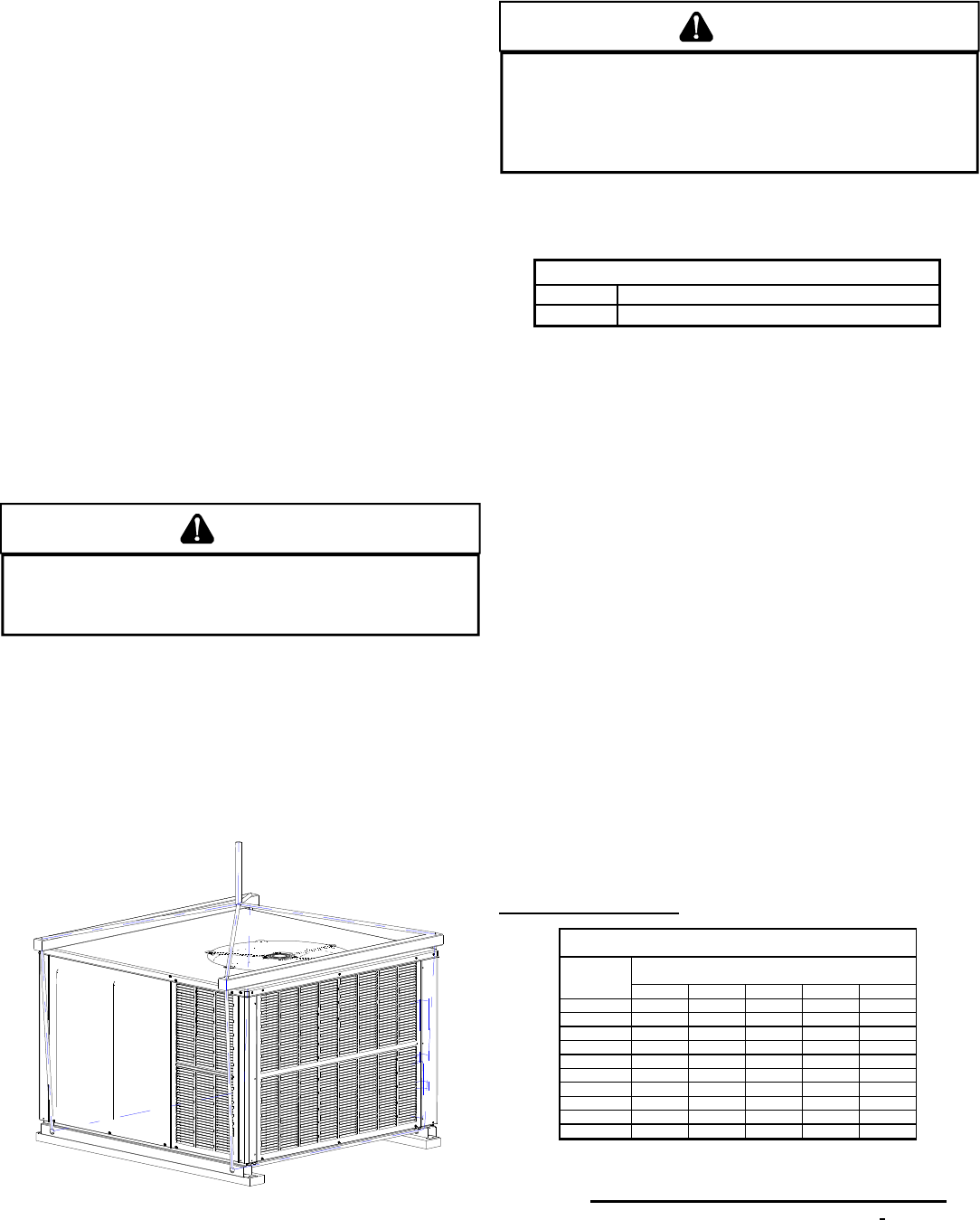
RIGGING DETAILS
WARNING
TO PREVENT PROPERTY DAMAGE, THE UNIT SHOULD REMAIN IN AN UPRIGHT
POSITION DURING ALL RIGGING AND MOVING OPERATIONS. TO FACILITATE
LIFTING AND MOVING WHEN A CRANE IS USED, PLACE THE UNIT IN AN
ADEQUATE CABLE SLING.
Important: If using bottom discharge with roof curb, ductwork should
be attached to the curb prior to installing the unit. Ductwork dimen-
sions are shown in roof curb installation instructions.
Refer to the Roof Curb Installation Instructions for proper curb in-
stallation. Curbing must be installed in compliance with the National
Roofing Contractors Association Manual.
Lower unit carefully onto roof mounting curb. While rigging unit,
center of gravity will cause condenser end to be lower than supply
air end.
Rigging
GAS PIPING
IMPORTANT NOTE: This unit is factory set to operate on natural
gas at the altitudes shown on the rating plate.
WARNING
TO AVOID PROPERTY DAMAGE, PERSONAL INJURY OR DEATH WHEN EITHER
USING PROPANE GAS ALONE OR AT HIGHER ALTITUDES, OBTAIN AND INSTALL
THE PROPER CONVERSION KIT(S). FAILURE TO DO SO CAN RESULT IN
UNSATISFACTORY OPERATION AND/OR EQUIPMENT DAMAGE. HIGH ALTITUDE
KITS ARE FOR U.S. INSTALLATIONS ONLY AND ARE NOT APPROVED FOR USE
IN CANADA.
The rating plate is stamped with the model number, type of gas and
gas input rating. Make sure the unit is equipped to operate on the
type of gas available. Conversion to LP gas is permitted with the
use of the factory authorized conversion kit LPT-00A.
Inlet Gas Pressure
Natural Min. 5.0" W.C., Max. 10.0" W.C.
Propane Min. 11.0" W.C., Max. 13.0" W.C.
Inlet Gas Pressure Must Not Exceed the Maximum Value Shown in Table
Above.
The minimum supply pressure should not vary from that shown in
the table above because this could prevent the unit from having
dependable ignition. In addition, gas input to the burners must not
exceed the rated input shown on the rating plate. Overfiring of the
unit could result in premature heat exchanger failure.
HIGH ALTITUDE DERATE (U.S. INSTALLATIONS ONLY)
IMPORTANT NOTE: The gas/electric units naturally derate with al-
titude. Do not attempt to increase the firing rate by changing ori-
fices or increasing the manifold pressure. This can cause poor com-
bustion and equipment failure. At all altitudes, the manifold pres-
sure must be within 0.3 inches W.C. of that listed on the nameplate
for the fuel used. At all altitudes and with either fuel, the air tempera-
ture rise must be within the range listed on the unit nameplate.
Refer to the Installation Manual provided with the LP kit for conver-
sion from natural gas to propane gas and for altitude adjustments.
PIPING
IMPORTANT NOTE: To avoid possible unsatisfactory operation or
equipment damage due to under firing of equipment, do not under-
size the natural/propane gas piping from the meter/tank to the unit.
When sizing a trunk line, include all appliances on that line that
could be operated simultaneously.
The rating plate is stamped with the model number, type of gas
and gas input rating. Make sure the unit is equipped to operate on
the type of gas available. The gas line installation must comply
with local codes, or in the absence of local codes, with the latest
edition of the National Fuel Gas Code NFPA 54/ANSI Z223.1.
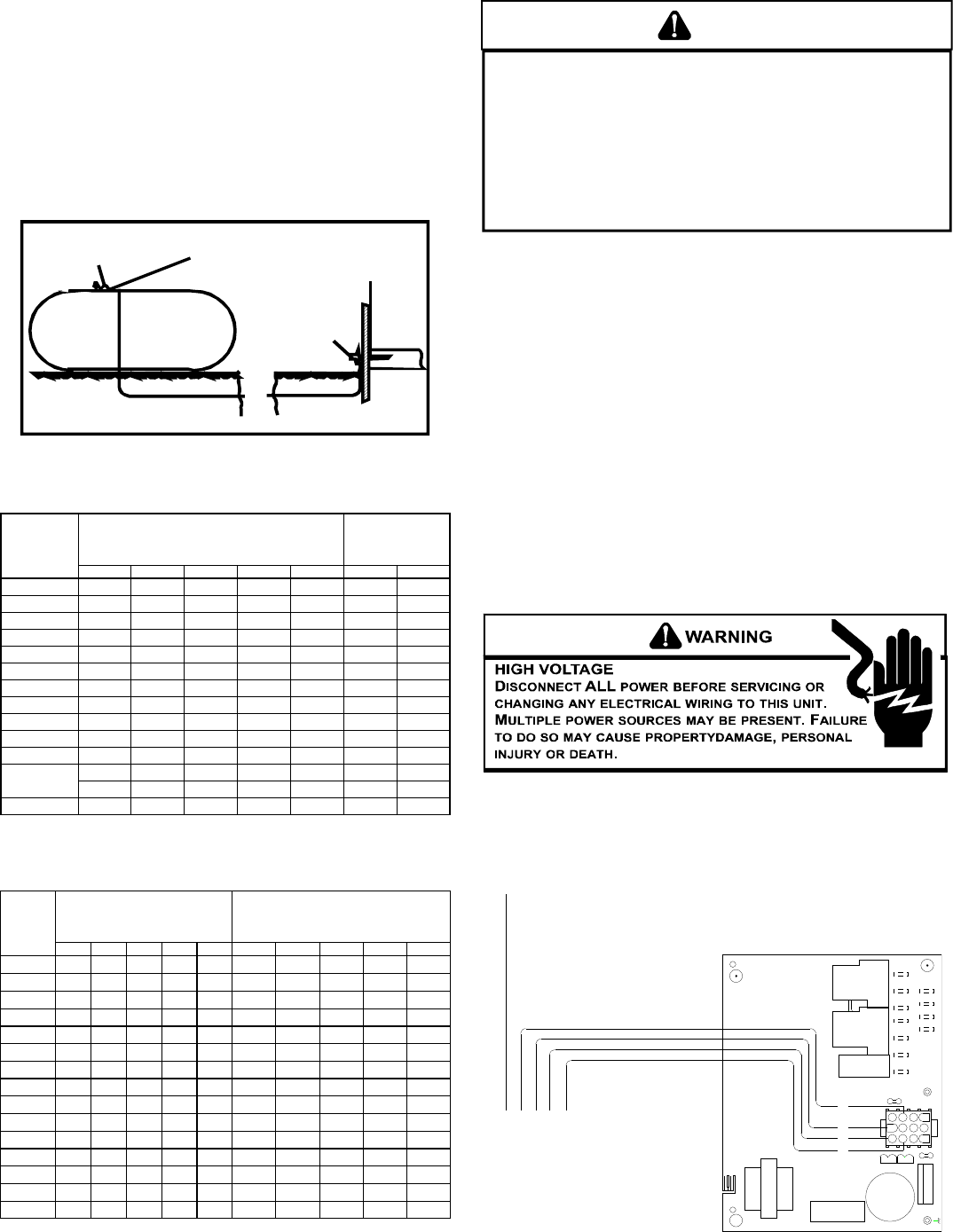
Natural Gas Connection
Len
g
th of
Pipe in Feet 1/2 3/4 11 1/4 1 1/2
10 132 278 520 1050 1600
20 92 190 350 730 1100
30 73 152 285 590 980
40 63 130 245 500 760
50 56 115 215 440 670
60 50 105 195 400 610
70 46 96 180 370 560
80 43 90 170 350 530
90 40 84 160 320 490
100 38 79 150 305 460
Pressure = .50 PSIG or less and Pressure Drop of 0.3" W.C. (Based
on 0.60 S
p
ecific Gravit
y
Gas
)
Natural Gas Capacity of Pipe
in Cubic Feet of Gas Per Hour (CFH)
Nominal Black Pipe Size (inches)
BTUH Furnace Input
Heatin
g
Value of Gas
(
BTU/Cubic Foot
)
CFH =
7
Refer to the Proper Piping Practice drawing for the general layout
at the unit. The following rules apply:
1. Use black iron pipe and fittings for the supply piping. The
use of a flex connector and/or copper piping is permitted
as long as it is in agreement with local codes.
2. Use pipe joint compound on male threads only. Pipe joint
compound must be resistant to the action of the fuel used.
3. Use ground joint unions.
4. Install a drip leg to trap dirt and moisture before it can enter
the gas valve. The drip leg must be a minimum of three
inches long.
5. Use two pipe wrenches when making connection to the gas
valve to keep it from turning.
6. Install a manual shut-off valve in a convenient location
(within six feet of unit) between the meter and the unit.
7. Tighten all joints securely.
8. The unit must be connected to the building piping by one
of the following methods:
• Rigid metallic pipe and fittings
• Semirigid metallic tubing and metallic fittings (Aluminum
alloy tubing must not be used in exterior locations)
• Listed gas appliance connectors used in accordance with
the terms of their listing that are completely in the same
room as the equipment
• In the prior two methods above the connector or tubing
must be protected from physical and thermal damage.
Aluminum alloy tubing and connectors must be coated to
protect against external corrosion when in contact with
masonry, plaster or insulation or are subject to repeated
wettings by liquids (water - not rain water, detergents or
sewage)
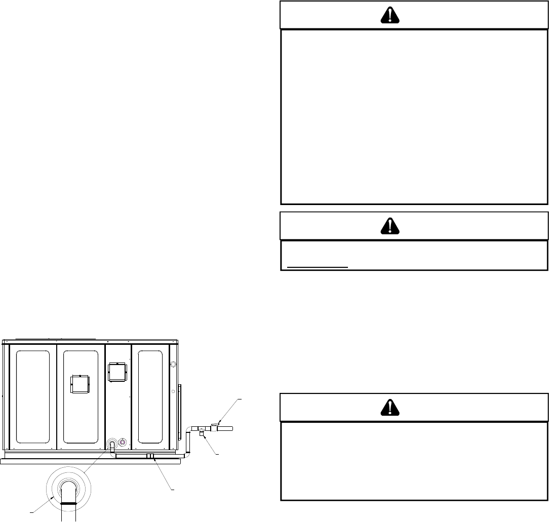
DRIP LEG
MANUAL
SHUT-OFF
VALVE
GROUND JOINT UNION
(INSTALLED AHEAD OF GAS VALVE)
GROMMET
Proper Piping Practice
NOTE: The unit gas supply entrance is factory sealed with plugs.
Keep plugs in place until gas supply is ready to be installed. Once
ready, replace the plugs with the supplied grommets and install gas
supply line.
GAS PIPING CHECKS
CAUTION
TO PREVENT PROPERTY DAMAGE OR PERSONAL INJURY DUE TO FIRE, THE
FOLLOWING INSTRUCTIONS MUST BE PERFORMED REGARDING GAS
CONNECTIONS AND PRESSURE TESTING:
• THE UNIT AND ITS GAS CONNECTIONS MUST BE LEAK TESTED BEFORE
PLACING IN OPERATION. BECAUSE OF THE DANGER OF EXPLOSION OR
FIRE, NEVER USE A MATCH OR OPEN FLAME TO TEST FOR LEAKS. NEVER
EXCEED SPECIFIED PRESSURES FOR TESTING. HIGHER PRESSURE MAY
DAMAGE GAS VALVE AND CAUSE OVERFIRING WHICH MAY RESULT IN
PREMATURE HEAT EXCHANGE FAILURE.
• THIS UNIT AND ITS SHUT-OFF VALVE MUST BE DISCONNECTED FROM
THE GAS SUPPLY DURING ANY PRESSURE TESTING OF THAT SYSTEM AT
TEST PRESSURES IN EXCESS OF 1/2 PSIG (3.48 KPA).
• THIS UNIT MUST BE ISOLATED FROM THE GAS SUPPLY SYSTEM BY
CLOSING ITS MANUAL SHUT-OFF VALVE DURING ANY PRESSURE
TESTING OF THE GAS SUPPLY PIPING SYSTEM AT TEST PRESSURES
EQUAL TO OR LESS THAN 1/2 PSIG (3.48 KPA).
WARNING
TO AVOID PROPERTY DAMAGE OR PERSONAL INJURY, BE SURE THERE IS
NO OPEN FLAME IN THE VICINITY DURING AIR BLEEDING.
There will be air in the gas supply line after testing for leaks
on a new installation. Therefore, the air must be bled from the
line by loosening the ground joint union until pure gas is
expelled. Tighten union and wait for five minutes until all gas
has been dissipated in the air. Be certain there is no open
flame in the vicinity during air bleeding procedure. The unit is
placed in operation by closing the main electrical disconnect
switch for the unit.
PROPANE GAS INSTALLATIONS
WARNING
TO AVOID PROPERTY DAMAGE, PERSONAL INJURY OR DEATH DUE TO FIRE
OR EXPLOSION CAUSED BY A PROPANE GAS LEAK, INSTALL A GAS
DETECTING WARNING DEVICE. SINCE RUST CAN REDUCE THE LEVEL
OF ODORANT IN PROPANE GAS, A GAS DETECTING WARNING DEVICE
IS THE ONLY RELIABLE WAY TO DETECT A PROPANE GAS LEAK.
CONTACT A LOCAL PROPANE GAS SUPPLIER ABOUT INSTALLING A
GAS DETECTING WARNING DEVICE.
IMPORTANT NOTE: Propane gas conversion kits must be
installed to convert units to propane gas.
All propane gas equipment must conform to the safety
standards of the National Board of Fire Underwriters (See NBFU
Manual 58).
For satisfactory operation, propane gas supply pressure must
be within 9.7 - 10.3 inches W.C. at the manifold with all gas
appliances in operation. Maintaining proper gas pressure
depends on three main factors:
1. Vaporization rate, which depends on (a) temperature of the
liquid, and (b) wetted surface area of the container or
containers.
2. Proper pressure regulation.
3. Pressure drop in lines between regulators, and between
second stage regulator and the appliance. Pipe size
required will depend on length of pipe run and total load of
all appliances.
8
WARNING
TO PREVENT PROPERTY DAMAGE OR SERIOUS PERSONAL INJURY DUE TO
FIRE OR EXPLOSION CAUSED BY A PROPANE GAS LEAK, INSTALL A GAS
DETECTING WARNING DEVICE.
IF THE PROPANE GAS UNIT IS INSTALLED IN AN EXCAVATED AREA OR A
CONFINED SPACE, A WARNING DEVICE IS REQUIRED DUE TO:
• PROPANE GAS IS HEAVIER THAN AIR AND ANY LEAKING GAS CAN
SETTLE IN ANY LOW AREAS OR CONFINED SPACES.
• PROPANE GAS ODORANT MAY FADE, MAKING THE GAS UNDETECTABLE
EXCEPT WITH A WARNING DEVICE.
ELECTRICAL WIRING
THERMOSTAT L OCATION
Mount the thermostat approximately five feet above the floor,
in an area that has an inside, vibration-free wall and has good
air circulation.
Movement of air must not be obstructed by furniture, door,
draperies, etc. The thermostat must not be mounted where it
will be affected by drafts, hot or cold water pipes or air ducts in
walls, radiant heat from fireplace, lamps, the sun, television,
etc. Consult the Instruction Sheet packaged with thermostat
for mounting instructions.
All units have one stage of heating and one stage of
mechanical cooling. Units which will have economizers may
use thermostats with one or two stages of cooling.
*PG1360***1A ONLY: These models have two stages of
mechanical cooling. A 1-stage heat, 2-stage cooling
thermostat is recommended for these models.
The units are designed for operation on 60 hertz current and
at voltages as shown on the rating plate. All internal wiring in
the unit is complete. It is necessary to bring in the power supply
to the contactor as shown on the unit wiring diagram which is
supplied with each unit. 24 volt wiring must be connected
between the unit control panel and the room thermostat.
C
3
2
1
6
5
9
8
11 12
Y
R
4
7
10
G
W
G
WYR
2
T1
C22
P2
P3
FUSE 3 AMP MAX
P1 12
1
7
445
3
3
6
9FS
6
10
7
F1
11
8
11
10
12
9
K1
12
T2
BREAK FOR TWO STAGE
COMPRESSOR
24VAC 50/60Hz 400mA MAX.
L1DI
K2
L1 HEATUNUSED
K4
K3
COOL
1068-83-400A
MODE L
1068-400
B18099-18
ANSI Z21.20 AUTOMATIC I GNITION SYSTEM
L2L2L2L2
ECON
120
135
150
SPEED-UP
LOW VOLTAGE
CONNECTOR
Low Voltage Wiring
TANKS AND PIPING
Complete information regarding tank sizing for vaporization,
recommended regulator settings and pipe sizing is available
from most regulator manufacturers and propane gas suppliers.
Since propane gas will quickly dissolve white lead or most
standard commercial compounds, special pipe dope must be
used. Shellac base compounds resistant to the actions of
liquefied petroleum gases such as Gasolac®, Stalactic®,
Clyde’s® or John Crane® are satisfactory.
See below for typical propane gas piping.
200 PSIG
Maximum
5 to 15 PSIG
(20 PSIG Max.) Continuous
11" W.C.
Second Stage
Regulator
First Stage
Regulator
Typical Propane Gas Piping
Sizing Between First and Second Stage Regulator
Maximum Propane Capacities listed are based on 1 PSIG Pressure Drop at 10
PSIG Setting. Capacities in 1,000 BTU/HR
3/8" 1/2" 5/8" 3/4" 7/8" 1/2" 3/4"
30 309 700 1,303 2,205 3,394 1,843 3,854
40 265 599 1,115 1,887 2,904 1,577 3,298
50 235 531 988 1,672 2,574 1,398 2,923
60 213 481 896 1,515 2,332 1,267 2,649
70 196 446 824 1,394 2,146 1,165 2,437
80 182 412 767 1,297 1,996 1,084 2,267
90 171 386 719 1,217 1,873 1,017 2,127
100 161 365 679 1,149 1,769 961 2,009
150 130 293 546 923 1,421 772 1,613
200 111 251 467 790 1,216 660 1,381
250 90 222 414 700 1,078 585 1,224
300 89 201 378 634 976 530 1,109
350 82 185 345 584 898 488 1,020
400 76 172 321 543 836 454 949
To convert to Capacities at 15 PSIG Settings -- Multiply by 1.130
To convert to Capacities at 5 PSIG Settings -- Multiply by 0.879
PIPE OR
TUBING
LENGTH,
FEET
NOMINAL PIPE SIZE,
SCHEDULE 40
TUBING SIZE, O.D., TYPE L
Sizing Between Single or Second Stage Regulator and Appliance*
Maximum Propane Capacities Listed are Based on 1/2" W.C. Pressure Drop at
11" W.C. Setting. Capacities in 1,000 BTU/HR
3/8" 1/2" 5/8" 3/4" 7/8" 1/2" 3/4" 1" 1-1/4" 1-1/2"
10 49 110 206 348 539 291 608 1,146 2,353 3,525
20 34 76 141 239 368 200 418 788 1,617 2,423
30 27 61 114 192 296 161 336 632 1,299 1,946
40 23 52 97 164 253 137 284 541 1,111 1,665
50 20 46 86 146 224 122 255 480 985 1,476
60 19 42 78 132 203 110 231 436 892 1,337
80 16 36 67 113 174 94 198 372 764 1,144
100 14 32 59 100 154 84 175 330 677 1,014
125 12 28 52 89 137 74 155 292 600 899
150 11 26 48 80 124 67 141 265 544 815
200 10 22 41 69 106 58 120 227 465 697
250 9 19 36 61 94 51 107 201 412 618
300 8 18 33 55 85 46 97 182 374 560
350 7 16 30 51 78 43 89 167 344 515
400 7 15 28 47 73 40 83 156 320 479
*DATA IN ACCORDANCE WITH NFPA PAMPHLET NO. 54
NOMINAL PIPE SIZE,
SCHEDULE 40
TUBING SIZE, O.D., TYPE L
PIPE OR
TUBING
LENGTH,
FEET
Table 3 - Propane Gas Pipe Sizing
9
Electrical Power Directly To Junction Box
Electrical Power Routed Through Bottom of Unit
Note:Junction box location
shown is optional and is
for illustration purposes only.
JUNCTION BOX
Typical Electrical Wiring Unit Voltage
UNIT V OLTAGE
The unit transformer is factory connected for 230V operation.
If the unit is to operate on 208V, reconnect the transformer
primary lead as shown on the unit wiring diagram. The induced
draft blower on some models is equipped with a 230V lead
(red) and a 208V lead (black). If equipped, connect the induced
draft blower 208V lead (black) in place of the 230V lead (red).
Tape the unused 230V lead.
HEAT ANTICIPATOR S ETTING
The heat anticipator is to be set by measuring the load
(amperage) at the “R” circuit. Follow the instructions provided
by the thermostat for more details.
G
Y
W
R
R
W
Y
G
From
Unit
Typical Thermostat and Unit 24 V Wiring Hookup
C
3
2
1
6
5
9
8
11 12
Y
R
4
7
10
G
W
GW
Y1
R
2
T1
C22
P2
P3
FUSE 3 AMP MAX
P1 12
1
7
445
3
3
6
9FS
6
10
7
F1
11
8
11
10
12
9
K1
12
T2
BREAK FOR TWO STAGE
COMPRESSOR
24VAC 50/60Hz 400mA MAX.
L1DI
K2
L1 HEATUNUSED
K4
K3
COOL
1068-83-400A
MODEL
1068-400
B18099-18
ANSI Z21.20 AUTOMATIC IGNITI ON SYSTEM
L2L2L2L2
ECON
120
135
150
SPEED-UP
LOW VOLTAGE
CONNECTOR
Y/Y2
Low Voltage Wiring-*PG1360***1A Only
Refer to the unit wiring diagram for electrical connections.
When installed, the unit must be electrically grounded in
accordance with local codes or in the absence of local codes,
with the National Electrical Code, ANSI/NFPA No. 70, and/or
the CSA C22.1 Electrical Code. Ensure low voltage
connections are waterproof.
WARNING
TO AVOID THE RISK OF ELECTRICAL SHOCK, WIRING TO THE UNIT MUST BE
POLARIZED AND GROUNDED.
CAUTION
TO AVOID PROPERTY DAMAGE OR PERSONAL INJURY DUE TO FIRE, USE
ONLY COPPER CONDUCTORS.
CAUTION
TO PREVENT IMPROPER AND DANGEROUS OPERATION DUE TO WIRING ERRORS,
LABEL ALL WIRES PRIOR TO DISCONNECTION WHEN SERVICING CONTROLS.
VERIFY PROPER OPERATION AFTER SERVICING.
For unit protection, use a fuse or HACR circuit breaker that is
in excess of the circuit ampacity, but less than or equal to the
maximum overcurrent protection device. DO NOT EXCEED
THE MAXIMUM OVERCURRENT DEVICE SIZE SHOWN ON
UNIT DATA PLATE.
All line voltage connections must be made through
weatherproof fittings. All exterior power supply and ground
wiring must be in approved weatherproof conduit. Low voltage
wiring from the unit control panel to the thermostat requires
coded cable. See below for ground level and rooftop wiring.
10
G
Y
W
R
R
W
Y1
G
From
Unit
Y/Y2
Y/Y2
Typical 2-Stage Cool Thermostat and
Unit 24 V Wiring Hookup
*PG1360***1A Only
CIRCULATING AIR AND FILTERS
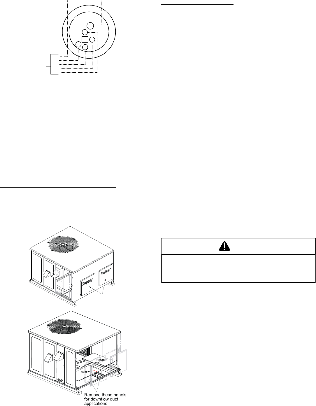
AIRFLOW C ONVERSION
Units can easily be converted from horizontal to down-
discharge airflow delivery. In down-discharge or high static
installations, the installer should measure the total external
static and review the blower performance charts before
performing the installation. In some installations it will be
necessary to change the blower speed to provide proper air
flow.
Horizontal Air Flow (Applies to 3 phase models)
Single phase models are shipped without horizontal duct
covers. If needed, these kits may be ordered through
Goodman’s Service Parts department.
Remove supply and return duct covers which are attached to
the unit as shown below.
Remove these covers
for horizontal duct
applications
Duct Cover Installation
Down Discharge Applications
Cut insulation around bottom openings and remove panels
from the bottom of the unit, saving the screws holding the
panels in place.
NOTE: Single phase models require installation of horizontal
duct kit #20464501PDGK (medium chassis) and
#20464502PDGK (large chassis).
DUCTWORK
Duct systems and register sizes must be properly designed
for the C.F.M. and external static pressure rating of the unit.
Ductwork should be designed in accordance with the
recommended methods of Air Conditioning Contractors of
America Manual D (Residential) or Manual Q (Commercial).
All ductwork exposed to the outdoors must include a
weatherproof barrier and adequate insulation.
A duct system should be installed in accordance with
Standards of the National Board of Fire Underwriters for the
Installation of Air Conditioning, Warm Air Heating and
Ventilating Systems. Pamphlets No. 90A and 90B.
The supply duct from the unit through a wall may be installed
without clearance. However, minimum unit clearances as
shown in the appendix must be maintained. The supply duct
should be provided with an access panel large enough to
inspect the air chamber downstream of the heat exchanger. A
cover should be tightly attached to prevent air leaks.
For duct flange dimensions on the unit refer to the Unit
Dimension illustration in the appendix.
For down-discharge applications, the ductwork should be
attached to the roof curb prior to installing the unit. Ductwork
dimensions are shown in the roof curb installation manual.
If desired, supply and return duct connections to the unit may
be made with flexible connections to reduce possible unit
operating sound transmission.
FILTERS
CAUTION
TO PREVENT PROPERTY DAMAGE DUE TO FIRE AND LOSS OF
EQUIPMENT EFFICIENCY OR EQUIPMENT DAMAGE DUE TO DUST AND LINT
BUILD UP ON INTERNAL PARTS, NEVER OPERATE UNIT WITHOUT AN AIR
FILTER INSTALLED IN THE RETURN AIR SYSTEM.
Even though a return air filter is not supplied with this unit,
there must be a means of filtering all return air. The
*PG1336(3A,4A), *PG1342, *PG1348, and *PG1360 models
are provided with internal filter racks for down-discharge
applications. All units may be externally filtered.
Refer to the unit filter size chart in the appendix for filter size
information.
Filters installed external to the unit should be sized in
accordance with their manufacturer recommendations. A
throwaway filter must be sized for a maximum face velocity of
300 feet per minute.
Filter Installation
Important: When installing a filter, the air flow arrows on the
filter must point toward the circulator blower.
11
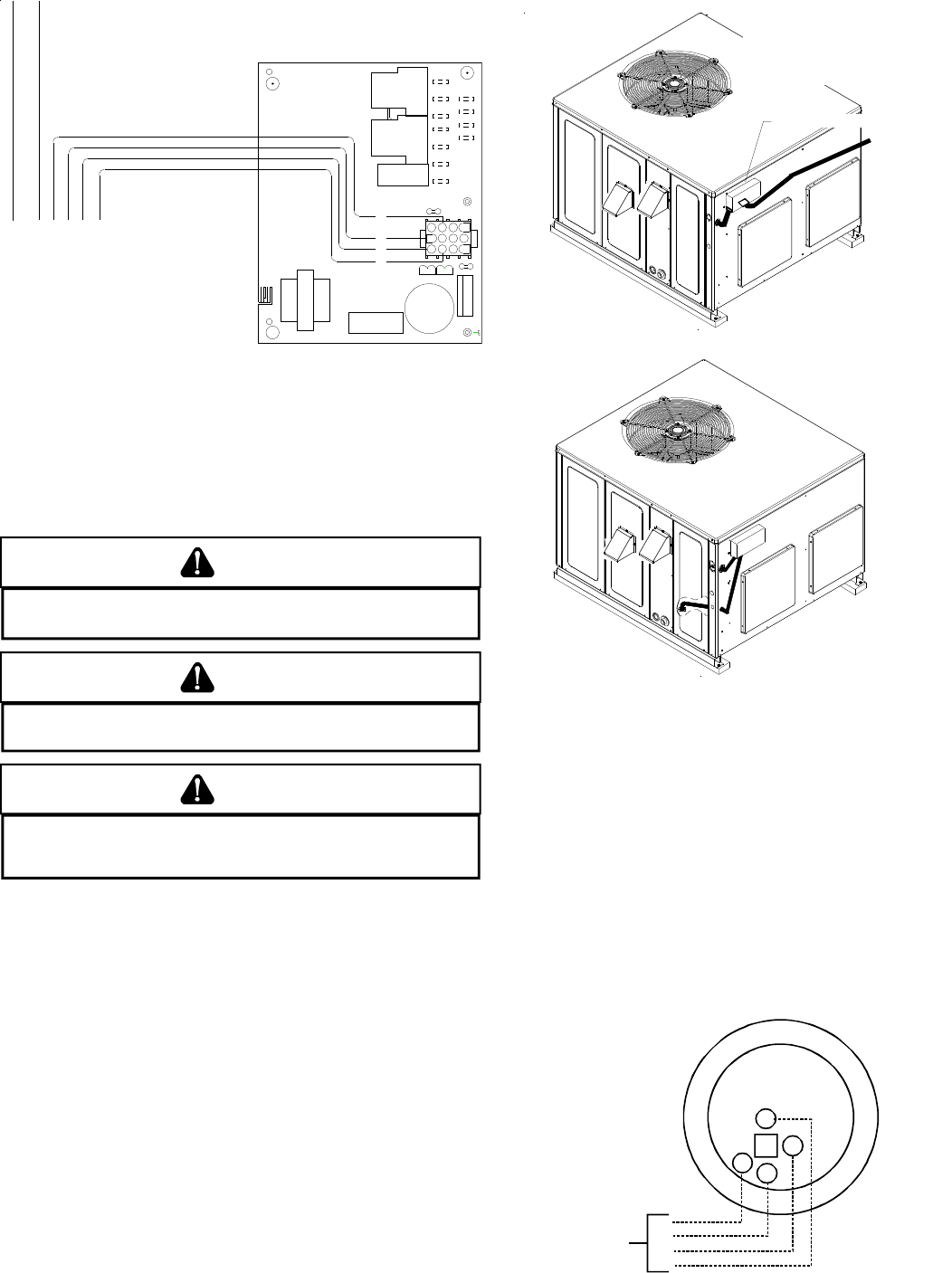
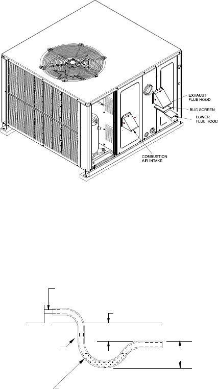
VENTING
NOTE: Venting is self-contained. Do not modify or block.
FLUE H OOD I NSTALLATION
Install the flue hood and bug screen prior to operation of the
unit.
To install the flue hood cover and bug screen:
1. Remove the flue hood and bug screen from inside the
heat exchanger compartment.
2. Slide the bug screen over the flanges of the flue hood and
attach the flue hood and screen to the unit with the sheet
metal screws provided.
Flue Hood and Bug Screen Installation
CONDENSATE DRAIN
CONDENSATE D RAIN C ONNECTION
A 3/4” NPT drain connection is supplied for condensate piping. An
external trap must be installed for proper condensate drainage.
DRAIN
CONNECTION
UNIT 2" MINIMUM
FLEXIBLE
TUBING-HOSE
OR PIPE 3" MINIMUM
A POSITIVE LIQUID
SEAL IS REQUIRED
Drain Connection
NORMAL SEQUENCES OF OPERATION
HEATING
This unit is equipped with an ignition control that automatically
lights the main burner. DO NOT attempt to light the main
burners by any other method.
1. Thermostat calls for heat. The induced draft blower
energizes for a 15-second pre-purge.
2. The spark igniter and gas valve energizes for 7 seconds.
NOTE: The igniter produces a very intense electrical spark
that ignites the gas.
3. The 30-second HEAT FAN ON delay time begins.
*PG13(48,60)***1A ONLY: Heat on delay begins when
thermostat calls for heat. ECM motor is energized
approximately 45 seconds later. NOTE: ECM motor may
operate at approximately 100 CFM or less during the 45
second on delay period. ECM motor will energize at heating
speed after the 45 second delay regardless of the status
of the main burner flame.
4. The unit delivers heat to the conditioned space until the
thermostat is satisfied.
5. The gas valve deenergizes. The induced draft blower
continues operation for a 29-second post-purge.
6. Ignition control begins timing the HEAT FAN OFF delay.
There is an adjustable HEAT FAN OFF delay of
approximately 120/135/150 seconds (factory set at 150).
After the HEAT FAN OFF delay time has elapsed, the blower
will deenergize. This allows any additional heat in the
heat exchanger to be transferred to the conditioned space.
*PG13(48,60)***1A ONLY: HEAT FAN OFF delay is fixed at
180 seconds. Airflow level is 50% of nominal heating
airflow.
COOLING
1. Thermostat calls for cooling. The compressor and outdoor
fan are energized.
2. Approximately seven seconds later, the indoor fan starts.
3. The unit will deliver cooling to the conditioned space until
the thermostat is satisfied.
4. The compressor and outdoor fan will be deenergized when
the thermostat opens.
5. The indoor fan continues to run for approximately 60
seconds after the thermostat is satisfied. This allows
additional cooling from the indoor coil to be transferred to
the conditioned space. Then, the indoor fan stops.
*PG1348***1A ONLY:
1. Thermostat calls for cooling. Outdoor fan and compressor
are energized. ECM motor is energized almost immediately
for 30 seconds at 50% of the nominal airflow. Airflow then
increases to nominal airflow.
2. The unit will deliver cooling to the conditioned space until
thermostat is statisfied.
3. The outdoor fan and compressor will be de-energized when
thermostat opens.
4. ECM motor continues to operate for approximately 60
seconds at 50% of nominal airflow after thermostat opens.
*PG1360***1A ONLY:
1. Thermostat calls for low stage cooling. Outdoor fan and
low stage compressor are energized. ECM motor is
energized almost immediately for 30 seconds at 50% of
the nominal low stage airflow. Airflow then increases to
nominal low stage airflow.
If thermostat calls for high stage cooling, outdoor fan and
low and high stage compressor is energized. ECM motor is
energized almost immediately for 30 seconds at 50% of
the nominal high stage airflow. Airflow then increases to
nominal high stage airflow.
2. The unit will deliver cooling to the conditioned space until
thermostat is satisfied.
3. The outdoor fan and low stage compressor (or low and high
stage compressor) will be de-energized when thermostat
opens.
4. ECM motor continues to operate for approximately 60
seconds at 50% of nominal low stage airflow (or high
stage airflow if thermostat call was for high stage cooling)
after thermostat opens.
12
NOTE: A 180-second anti-short cycle is integral to the control and
prevents recycling of the compressor.
FAN ONLY
1. Thermostat calls for FAN ONLY by energizing “G”.
2. Approximately seven seconds later, the indoor fan starts.
3. The indoor fan continues to run for approximately 60
seconds after “G” is de-energized.
*PG13(48,60)***1A ONLY:
1. Thermostat calls for FAN ONLY by energizing “G”.
2. ECM motor is energized almost immediately at
approximately 30% of the nominal high stage cooling
airflow, depending on setting (see “Blower Speed
Adjustment” section).
3. ECM is de-energized almost immediately after “G” is de-
energized.
STARTUP, ADJUSTMENTS, AND CHECKS
HEATING S TARTUP
This unit is equipped with an electronic ignition device to
automatically light the main burners. It also has a power vent
blower to exhaust combustion products.
On new installations, or if a major component has been
replaced, the operation of the unit must be checked.
Check unit operation as outlined in the following instructions.
If any sparking, odors, or unusual sounds are encountered,
shut off electrical power and recheck for wiring errors, or
obstructions in or near the blower motors. Duct covers must
be removed before operating unit.
Heat Anticipator Setting
Set the heat anticipator on the room thermostat to 0.4 amps to
obtain the proper number of heating cycles per hour and to
prevent the room temperature from overshooting the room
thermostat setting.
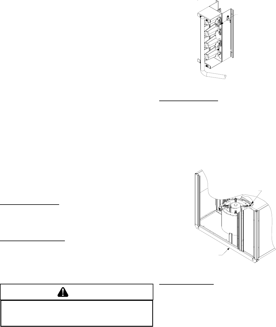
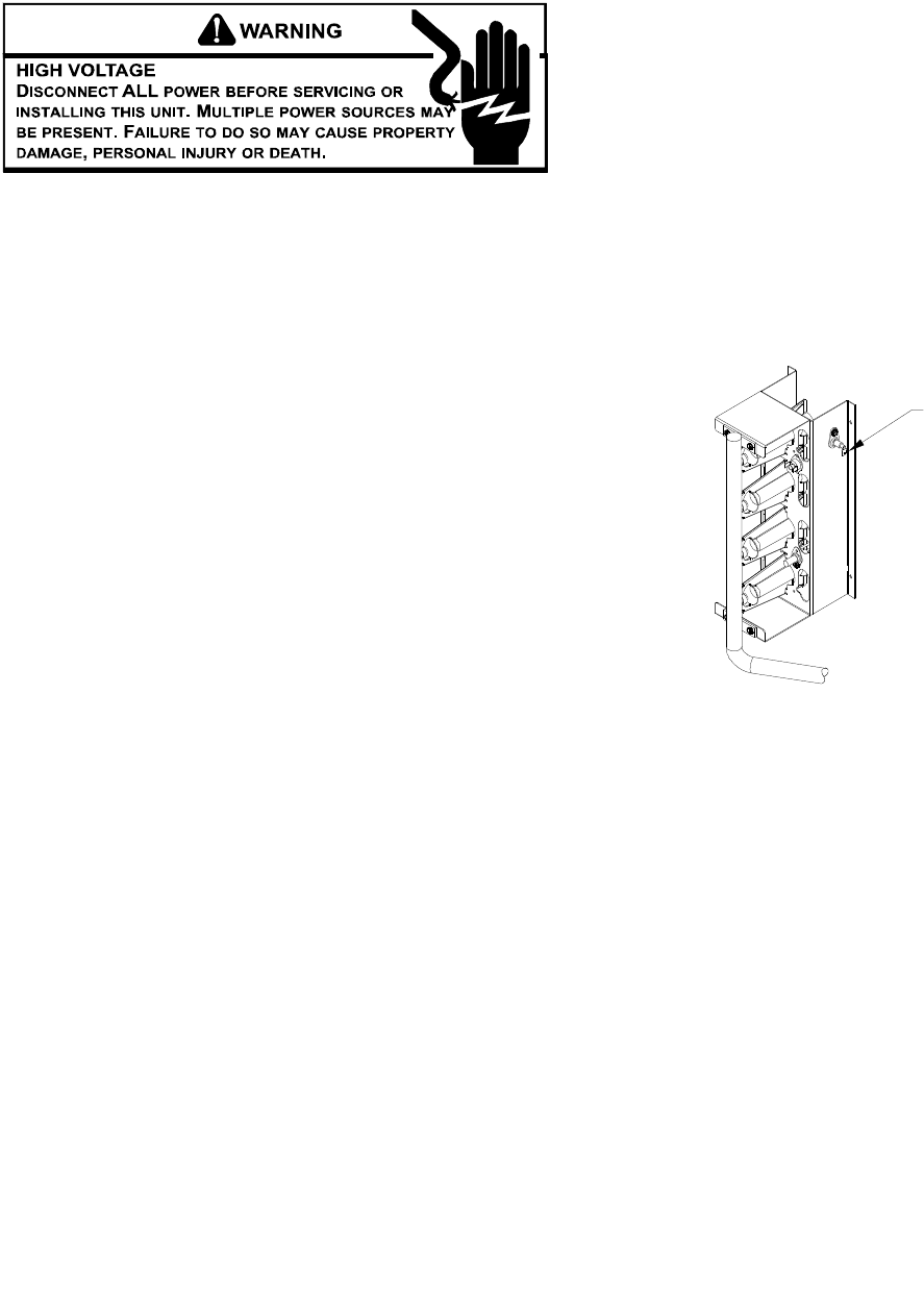
Rollout Protection Control
The rollout protection device opens, cutting power to the gas
valve, if the flames from the burners are not properly drawn
into the heat exchanger. The rollout protection device is located
on the burner bracket. The reason for elevated temperatures
at the control should be determined and repaired prior to
resetting this manual reset control.
WARNING
TO AVOID PROPERTY DAMAGE, PERSONAL INJURY OR DEATH DUE TO FIRE
OR EXPLOSION, A QUALIFIED SERVICER MUST INVESTIGATE THE REASON FOR
THE ROLLOUT PROTECTION DEVICE TO OPEN BEFORE MANUALLY RESETTING
THE ROLLOUT PROTECTION DEVICE.
Rollout Protection
Rollout Protection on Burner Bracket
Secondary Limit Control
The secondary limit control is located on the top of the blower
scroll assembly. This control opens when elevated
temperatures are sensed. Elevated temperatures at the
control are normally caused by blower failure. The reason for
the opening should be determined and repaired prior to
resetting.
If the power to the unit is interrupted during the heating cycle,
it may cause the secondary limit to trip. Once the blower
compartment temperature drops below the limit reset
temperature, the limit will automatically reset.
Secondary
Control Limit
Back of Unit
Secondary Limit Control
Pre-Operation Checks
1. Close the manual gas valve external to the unit.
2. Turn off the electrical power supply to the unit.
3. Set the room thermostat to its lowest possible setting.
4. Remove the heat exchanger door on the side of the unit by
removing screws.
5. This unit is equipped with an ignition device which
automatically lights the main burner. DO NOT try to light
burner by any other method.
6. Move the gas control valve switch to the OFF position. Do
not force.
7. Wait five minutes to clear out any gas.
8. Smell for gas, including near the ground. This is important
because some types of gas are heavier than air. If you
have waited five minutes and you do smell gas,
immediately follow the warnings on page 3 of this manual.
13
Gas Line
Gas
Shutoff
Valve
Gas Line
To Furnace
Drip Leg Cap
With Fitting
Manometer Hose
Manometer
Open To
Atmosphere
Measuring Inlet Gas Pressure
Alternate Method
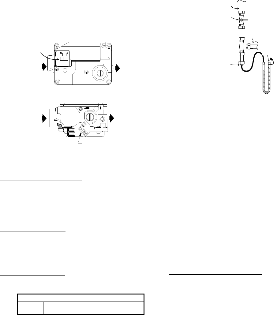
Manifold Pressure Check
The gas valve has a tapped opening to facilitate measurement
of the manifold pressure. A “U” Tube manometer having a scale
range from 0 to 12 inches of water should be used for this
measurement. The manifold pressure must be measured with
the burners operating.
To adjust the pressure regulator, remove the adjustment screw
or cover on the gas valve. Turn out (counterclockwise) to
decrease pressure, turn in (clockwise) to increase pressure.
Only small variations in gas flow should be made by means
of the pressure regulator adjustment. In no case should the
final manifold pressure vary more than plus or minus 0.3
inches water column from the specified nominal pressure.
Any major changes in flow should be made by changing the
size of the burner orifices. The measured input rate to the
furnace must not exceed the rating specified on the unit rating
plate.
For natural gas, the manifold pressure must be between 3.2
and 3.8 inches water column (3.5 nominal).
For propane gas, the manifold pressure must be between 9.7
and 10.3 inches water column (10.0 nominal).
Gas Input (Natural Gas Only) Check
To measure the gas input use a gas meter and proceed as
follows:
1. Turn off gas supply to all other appliances except the unit.
2. With the unit operating, time the smallest dial on the meter
for one complete revolution. If this is a 2 cubic foot dial,
divide the seconds by 2; if it is a 1 cubic foot dial, use the
seconds as is. This gives the seconds per cubic foot of gas
being delivered to the unit.
3. INPUT=GAS HTG VALUE x 3600 / SEC. PER CUBIC FOOT
Example: Natural gas with a heating value of 1000 BTU per cubic
foot and 34 seconds per cubic foot as determined by Step 2, then:
Input = 1000 x 3600 / 34 = 106,000 BTU per Hour. NOTE:
BTU content of the gas should be obtained from the gas
supplier. This measured input must not be greater than
shown on the unit rating plate.
4. Relight all other appliances turned off in step 1. Be sure all
pilot burners are operating.
If having waited for five minutes and no gas smell is noted,
move the gas control valve switch to the ON position.
9. Replace the heat exchanger door on the side of the unit.
10. Open the manual gas valve external to the unit.
11. Turn on the electrical power supply to the unit.
12. Set the thermostat to desired setting.
OUTLET
INLET
Gas Valve
On/Off
Selector
Switch
White-Rodgers Model 36F22
Gas Valve
On/Off
Selector
Switch
INLET OUTLE
T
White-Rodgers 36G22
Gas Supply And Manifold Check
Gas supply pressure and manifold pressure with the burners
operating must be as specified on the rating plate.
Gas Inlet Pressure Check
Gas inlet pressure must be checked and adjusted in
accordance to the type of fuel being consumed.
With Power And Gas Off:
1. Connect a water manometer or adequate gauge to the inlet
pressure tap of the gas valve.
Inlet gas pressure can also be measured by removing the
cap from the dripleg and installing a predrilled cap with a
hose fitting.
With Power And Gas On:
2. Put unit into heating cycle and turn on all other gas
consuming appliances.
Natural Min. 5.0" W.C., Max. 10.0" W.C.
Propane Min. 11.0" W.C., Max. 13.0" W.C.
Inlet Gas Pressure
NOTE: Inlet Gas Pressure Must Not Exceed the Maximum Value
Shown.
If operating pressures differ from above, make necessary
pressure regulator adjustments, check piping size, etc., and/
or consult with local utility.
14
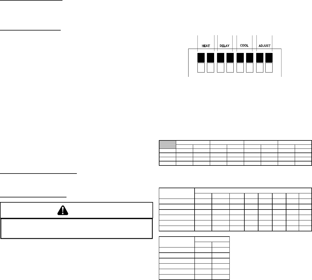
(switches 1 and 2) provides airflow adjustment for heating
airflow. The “COOL” adjustment function (switches 5 and 6)
provides airflow adjustments for cooling airflow. The
“ADJUST” function (switches 7 and 8) will adjust the heating
AND cooling airflow +10% or - 15%. The “DELAY” function
(switches 3 and 4) is not field adjustable.
O
N
To adjust the HEAT, COOL or ADJUST functions, simply change
the ON/OFF position of the appropriate dipswitches. The table
below shows the ON/OFF combinations for the various switches
and the corresponding A, B, C, or D taps. Refer to the Product
Data Book applicable to your model for airflow tables and
temperature rise. The “Dipswitch Position” table below shows
the factory dipswitch settings for each model. The “CFM” table
below shows the nominal heating and cooling CFM for each
model.
12345678
A OFF OFF OFF OFF OFF OFF OFF OFF
B ON OFF ON OFF ON OFF ON OFF
C OFF ON OFF ON OFF ON OFF ON
D ONONONONONONON*ON*
‡ Factory Set; not field adjustable
* Tap D has no effect on airflow
ADJUSTHEAT DELAY‡ COOL
Dipswitch Settings and Corresponding Tap
1 2 345678
GPG13480701* ON ON OFF OFF ON OFF OFF OFF
GPG13480901* OFF ON OFF OFF ON OFF OFF OFF
GPG13481151* ON OFF OFF OFF ON OFF OFF OFF
GPG13600901* ON ON OFF OFF OFF OFF OFF OFF
GPG13601151* OFF ON OFF OFF OFF OFF OFF OFF
GPG13601401* ON OFF OFF OFF OFF OFF OFF OFF
HEAT COOL
GPG13480701* 1020 1540
GPG13480901* 1140 1540
GPG13481151* 1420 1540
GPG13600901* 1140 1810
GPG13601151* 1420 1810
GPG13601401* 1700 1810
Model DIP SWITCH POSITION
Model CFM
Unit dipswitches are factory set for each model, see label on
blower housing for CFM adjustment next to low voltage terminal
connections.
NOTE: Heating airflow must be adjusted to provide the tempera-
ture rise shown on rating plate.
*PG1360***1A ONLY: Low stage airflow is approximately 75%
of high stage cooling airflow. Example: High stage cooling
airflow is 1800 CFM. Low stage cooling airflow is 0.75*1800
CFM = 1350 CFM.
The adjustment factors for the ADJUST function are A = 1, B =
1.10 (+10%) and C = 0.85 (-15%). The D tap for the ADJUST
function has no effect on airflow. Example: Airflow tables
indicate 1425 CFM. With the ADJUST set to B tap, the CFM
becomes 1.10*1425 CFM = 1568 CFM.
Main Burner Flame Check
Flames should be stable, soft and blue (dust may cause
orange tips but they must not be yellow) and extending directly
outward from the burner without curling, floating or lifting off.
Temperature Rise Check
Check the temperature rise through the unit by placing
thermometers in supply and return air registers as close to the
unit as possible. Thermometers must not be able to sample
temperature directly from the unit heat exchangers, or false
readings could be obtained.
1. All registers must be open; all duct dampers must be in their
final (fully or partially open) position and the unit operated
for 15 minutes before taking readings.
2. The temperature rise must be within the range specified on
the rating plate.
NOTE: Air temperature rise is the temperature difference between
supply and return air.
With a properly designed system, the proper amount of
temperature rise will normally be obtained when the unit is
operated at rated input with the recommended blower speed.
If the correct amount of temperature rise is not obtained, it
may be necessary to change the blower speed. A higher blower
speed will lower the temperature rise. A slower blower speed
will increase the temperature rise.
NOTE: Blower speed MUST be set to give the correct air tempera-
ture rise through the unit as marked on the rating plate.
External Static Pressure Check
The total external static pressure must be checked on this
unit to determine if the airflow is proper.
Blower Speed Adjustments
WARNING
TO AVOID PERSONAL INJURY OR DEATH DUE TO ELECTRIC SHOCK, REMOVE
ELECTRICAL POWER FROM THE UNIT BEFORE CHANGING SPEED TAPS ON THE
BLOWER MOTOR.
Refer to the wiring diagram in the appendix to verify speed tap
settings.
Blower speeds are to be changed at the ignition control board.
Both heat speed and cool speed terminals are supplied on
the board along with two unused motor lead terminals.
*PG13(48, 60)***1B, 3A, 4A models are equipped with X-13
motors. X-13 motors are constant torque motors with very low
power consumption. This motor is energized by 24V. Adjust
the CFM for the unit by changing the 24V low voltage leads to
the speed terminal block on the motor.
Heating-White Lead Cooling-Yellow Lead
T1 - Low Speed T4 - Low Speed
T2 - Medium Speed T5 - High Speed
T3 - High Speed
*PG13(48, 60)***1A models are equipped with GE ECM
motors. These motors offer greater airflow flexibility as well
as dehumidification. The airflow delivery for these models
can be adjusted by changing the position of dip switches on
a low voltage terminal board. The figure below shows the
dipswitch layout on the low voltage terminal board as well as
the function of each set of switches. The “HEAT” function
15
Dehumidification
The GE ECM motor has the capability to provide increased
dehumidification during cooling operation. This is
accomplished by lowering the airflow to approximately 85%
of the nominal cooling airflow. Example: Unit is operating at
1400 CFM and humidistat calls for dehumidification. Resulting
airflow is 0.85* 1400 CFM = 1190 CFM.
To make use of this feature, a 24VAC humidistat which
opens on humidity rise is required. Connect humidistat to
the HUMIDISTAT/HUM terminal on the low voltage terminal
board (see wiring diagram in the appendix). Clip the HUM/
PJ6 jumper on the low voltage terminal board. The system
is now ready to provide dehumidification.
Limit Check
Check limit control operation after 15 minutes of operation
by blocking the return air grille(s).
1. After several minutes the main burners must go OFF.
Blower will continue to run.
2. Remove air restrictions and main burners will relight
after a cool down period of a few minutes.
Adjust the thermostat setting below room temperature.
1. Main burners must go OFF.
2. Circulating Air Blower will continue to run for 120, 135 or
150 seconds, depending on the setting.
*PG13(48,60)***1A ONLY: Circulating Air Blower will
continue to run for 180 seconds.
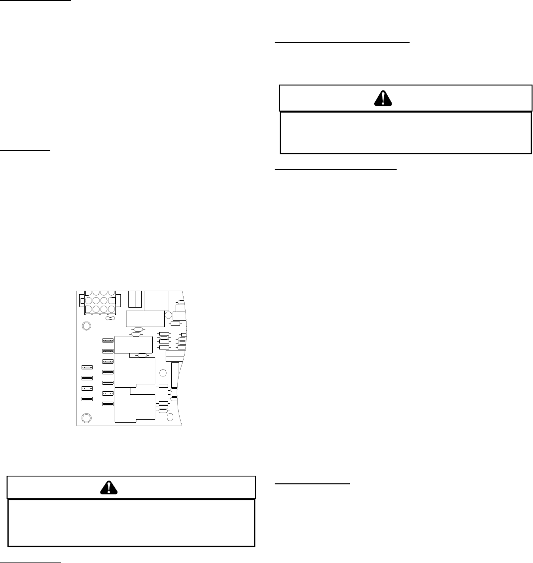
123
10
11 12
9
6
23
6
5
89
11 12
L2
L2L2
L2
D1 L1 L1 UNUSED HEAT COOL
FS
K2
K1
R8
R10
R3
K4
K3
R31
LED
1068-83-400A
C27
D3
R38
D9
D10
R34
R35
R4
R11
R42 D12
R36
D11
D14
C20
Z1
R29
R22
C13
R25
D5
D7
Control Board (Top)
NOTE: If necessary, adjust fan OFF delay settings to obtain satis-
factory comfort level.
WARNING
THIS UNIT MUST NOT BE USED AS A "CONSTRUCTION HEATER" DURING THE
FINISHING PHASES OF CONSTRUCTION ON A NEW STRUCTURE. THIS TYPE OF
USE MAY RESULT IN PREMATURE FAILURE OF THE UNIT DUE TO EXTREMELY
LOW RETURN AIR TERMPERATURES AND EXPOSURE TO CORROSIVE OR VERY
DIRTY ATMOSPHERES.
Unit Shutdown
1. Set the thermostat to lowest setting.
2. Turn off the electrical power supply to the unit.
3. Remove the heat exchanger door on the side of the unit by
removing screws.
4. Move the gas control valve switch to the OFF position. Do
not force.
5. Close manual gas shutoff valve external to the unit.
6. Replace the heat exchanger door on the unit.
7. If cooling and/or air circulation will be desired, turn ON the
electrical power.
COOLING S TARTUP
NOTE: Check all manual reset limit controls in heating circuit if
cooling mode does not operate.
Compressor Protection Devices
The compressor includes components which are designed
to protect the compressor against abnormal operating
conditions.
WARNING
TO PREVENT PERSONAL INJURY OR DEATH, ALWAYS DISCONNECT ELECTRICAL
POWER BEFORE INSPECTING OR SERVICING THE UNIT. ALL COMPRESSOR
PROTECTION DEVICES RESET AUTOMATICALLY, ENERGIZING THE CONTACTOR
AND OUTDOOR FAN.
Cooling Refrigerant Charging
Check unit charge before putting the cooling section into full
operation. The unit is factory charged with R-22 for nominal air
flow and static pressure conditions. The unit has a piston
flowrator expansion device.
NOTE: *PG1360 is equipped with a thermostatic valve expansion
device.
To ensure the unit is properly charged for the intended
application, check the unit refrigerant superheat at the
compressor. The refrigerant superheat is a function of outdoor
ambient temperature and return air temperature of the
conditioned space. It is the installing contractors responsibility
to ensure the proper refrigerant superheat at the compressor
is adjusted for each application. For example, 10 degree
refrigerant superheat level is adequate for a 95 degree outdoor
ambient temperature and a 78 - 80 degree for indoor return air
temperature. As the outdoor ambient temperature rises the
superheat decreases and as the outdoor ambient temperature
lowers the superheat increases. Proper superheat adjustment
optimizes cooling performance.
For models equipped with thermostatic expansion valve, charge
system to 12-14 degrees of subcooling, adjust expansion valve
stem for superheat setting when necessary.
NOTE: The expansion valve will not need adjustment for most
applications. Ensure system superheat is set between 10-12 degrees
after final adjustment.
Cooling Operation
NOTE: Mechanical cooling cannot be reliably provided at ambient
temperatures below 50° F.
1. Turn on the electrical power supply to the unit.
2. Place the room thermostat selector switch in the COOL
position (or AUTO if available, and if automatic changeover
from cooling to heating is desired).
3. Set the room thermostat to the desired temperature.
TROUBLESHOOTING
IGNITION CONTROL ERROR CODES
The following presents probable causes of questionable unit
operation. Refer to Diagnostic Indicator Chart for an
interpretation of the signal and to this section for an explanation.
Remove the control box access panel and note the number of
diagnostic LED flashes. Refer to Diagnostic Indicator Chart
for an interpretation of the signal and to this section for an
explanation.

16
ABNORMAL OPERATION - HEATING
Internal Control Failure
If the integrated ignition control in this unit encounters an
internal fault, it will go into a “hard” lockout and turn off the
diagnostic LED. If diagnostic LED indicates an internal fault,
check power supply to unit for proper voltage, check all fuses,
circuit breakers and wiring. Disconnect electric power for five
seconds. If LED remains off after restoring power, replace
control.
External Lockout
An external lockout occurs if the integrated ignition control
determines that a measurable combustion cannot be
established within three (3) consecutive ignition attempts. If
flame is not established within the seven (7) second trial for
ignition, the gas valve is deenergized, 15 second inter-purge
cycle is completed, and ignition is reattempted. The control
will repeat this routine three times if a measurable combustion
is not established. The control will then shut off the induced
draft blower and go into a lockout state.
If flame is established but lost, the control will energize the
circulator blower at the heat speed and then begin a new ignition
sequence. If flame is established then lost on subsequent
attempts, the control will recycle for four (4) consecutive
ignition attempts (five attempts total) before locking out.
The diagnostic fault code is 1 flash for a lockout due to failed
ignition attempts or flame dropouts. The integrated control
will automatically reset after one hour, or it can be reset by
removing the thermostat signal or disconnecting the electrical
power supply for over five seconds. If the diagnostic LED
indicates an external lockout, perform the following checks:
•Check the supply and manifold pressures
•Check the gas orifices for debris
•Check gas valve for proper operation
•Check secondary limit
A dirty filter, excessive duct static, insufficient air flow, a
faulty limit, or a failed circulator blower can cause this
limit to open. Check filters, total external duct static,
circulator blower motor, blower motor speed tap (see
wiring diagram), and limit. An interruption in electrical
power during a heating cycle may also cause the
auxiliary limit to open. The automatic reset secondary
limit is located on top of the circulator blower assembly.
•Check rollout limit
If the burner flames are not properly drawn into the heat
exchanger, the flame rollout protection device will open.
Possible causes are restricted or blocked flue passages,
blocked or cracked heat exchanger, a failed induced
draft blower, or insufficient combustion air. The rollout
protection device is a manual reset limit located on the
burner bracket. The cause of the flame rollout must be
determined and corrected before resetting the limit.
•Check flame sensor
A drop in flame signal can be caused by nearly invisible
coating on the sensor. Remove the sensor and carefully
clean with steel wool.
•Check wiring
Check wiring for opens/shorts and miswiring.
Important: If you have to frequently reset your gas/electric
package unit, it means that a problem exists that should be
corrected. Contact a qualified servicer for further
information.
Pressure Switch Stuck Open
A pressure switch stuck open can be caused by a faulty
pressure switch, faulty wiring, a disconnected or damaged
hose, a blocked or restricted flue, or a faulty induced draft
blower.
If the control senses an open pressure switch during the pre-
purge cycle, the induced draft blower only will be energized. If
the pressure switch opens after ignition has begun the gas
valve is deenergized, the circulator blower heat off cycle begins,
and the induced draft blower remains on. The diagnostic fault
code is two flashes.
Pressure Switch Stuck Closed
A stuck closed pressure switch can be caused by a faulty
pressure switch or faulty wiring. If the control encounters a
pressure switch stuck closed, the induced draft blower remains
off. The diagnostic LED code for this fault is three (3) flashes.
Open Thermal Protection Device
If the primary limit switch opens, the gas valve is immediately
deenergized, the induced draft and air circulating blowers are
energized. The induced draft and air circulator blowers remain
energized until the limit switch recloses. The diagnostic fault
code for an open limit is four (4) flashes.
A primary limit will open due to excessive supply air
temperatures. This can be caused by a dirty filter, excessive
duct static, insufficient air flow, or a faulty limit. Check filters,
total external duct static, blower motor, blower motor speed
tap (see wiring diagram), and limit. This limit will automatically
reset once the temperature falls below a preset level.
Flame Detected with Gas Valve Closed
If flame is detected with the gas valve deenergized, the
combustion and air circulator blowers are energized. The
diagnostic fault code is five (5) flashes for this condition. The
control can be reset by removing the power supply to the unit
or it will automatically reset after one hour. Miswiring is the
probable cause for this fault.
ABNORMAL OPERATION - COOLING
Short Cycle Compressor Delay
The automatic ignition control has a built-in feature that
prevents damage to the compressor in short cycling
situations. In the event of intermittent power losses or
intermittent thermostat operation, the ignition control will delay
output to the compressor contactor for three minutes from the
time power is restored. (Compressor is off a total of three
minutes). The diagnostic LED will flash six (6) times to indicate
the compressor contactor output is being delayed.
NOTE: Some electronic thermostats also have a built-in
compressor short cycle timer that may be longer than the three
minute delay given above. If you are using an electronic thermostat
and the compressor has not started after three minutes, wait an
additional five minutes to allow the thermostat to complete its short
cycle delay time.
17
MAINTENANCE
Have the gas heating section of the unit checked at least
once a year before the heating season begins, to be sure that
the combustion air inlet and flue outlet hoods are not blocked
by debris, which would prevent adequate combustion air and
a properly operating vent system.
FILTER REPLACEMENT OR CLEANING
A return air filter is not supplied with this unit; however, there
must be a means of filtering all of the return air. The filter(s)
may be located in the return air duct(s), or return air filter
grille(s). Consult with your installing dealer for the actual
location of the return air filter(s) for your unit.
Dirty filters are the most common cause of inadequate heating
or cooling performance. Filter inspection should be made at
least every two months; more often if necessary because of
local conditions and usage.
Dirty throwaway filters should be discarded and replaced with
a new, clean filter. Dirty permanent filters should be washed
with water, thoroughly dried and sprayed with a filter adhesive
before being reinstalled. (Filter adhesives may be found at
many hardware stores.) Permanent filters should last several
years. However, should one become torn or uncleanable, it
should be replaced.
CABINET F INISH M AINTENANCE
Use a fine grade automotive wax on the cabinet finish to
maintain the finish’s original high luster. This is especially
important in installations with extended periods of direct
sunlight.
CLEAN OUTSIDE COIL (QUALIFIED SERVICER ONLY)
The coil with the outside air flowing over it should be inspected
annually and cleaned as frequently as necessary to keep the
finned areas free of lint, hair and debris.
CONDENSER, EVAPORATOR, AND INDUCED DRAFT MOTORS
Bearings on the air circulating blower motor, condenser motor
and the combustion fan motor are permanently lubricated. No
additional oiling is required.
FLAME SENSOR (QUALIFIED SERVICER ONLY)
A drop in the flame current can be caused by a nearly invisible
coating on the flame sensor. This coating, created by the fuel
or combustion air supply, can be removed by carefully cleaning
the flame sensor with steel wool.
NOTE: After cleaning, the microamp signal should be stable and in
the range of 4 - 6 microamps DC.
Flame
Sensor
Flame Sensor
FLUE PASSAGES (QUALIFIED SERVICER ONLY)
At the start of each heating season, inspect and, if necessary,
clean the unit flue passage.
CLEANING FLUE PASSAGES (QUALIFIED SERVICER ONLY)
1. Shut off electric power and gas supply to the unit.
2. Remove burner assembly by disconnecting the gas line
and removing the manifold bracket from the partition panel.
3. Remove the flue from the induced draft blower and the
collector box cover from the partition panel.
4. The primary heat exchanger tubes can be cleaned using a
round wire brush attached to a length of high grade stainless
steel cable, such as drain cleanout cable. Attach a variable
speed reversible drill to the other end of the spring cable.
Slowly rotate the cable with the drill and insert it into one of
the primary heat exchanger tubes. While reversing the drill,
work the cable in and out several times to obtain sufficient
cleaning. Use a large cable for the large tube, and then
repeat the operation with a small cable for the smaller tube.
Repeat for each tube.
5. When all heat exchanger tubes have been cleaned,
replace the parts in the reverse order in which they were
removed.
6. To reduce the chances of repeated fouling of the heat
exchanger, perform the steps listed in “Startup,
Adjustments, and Checks”.
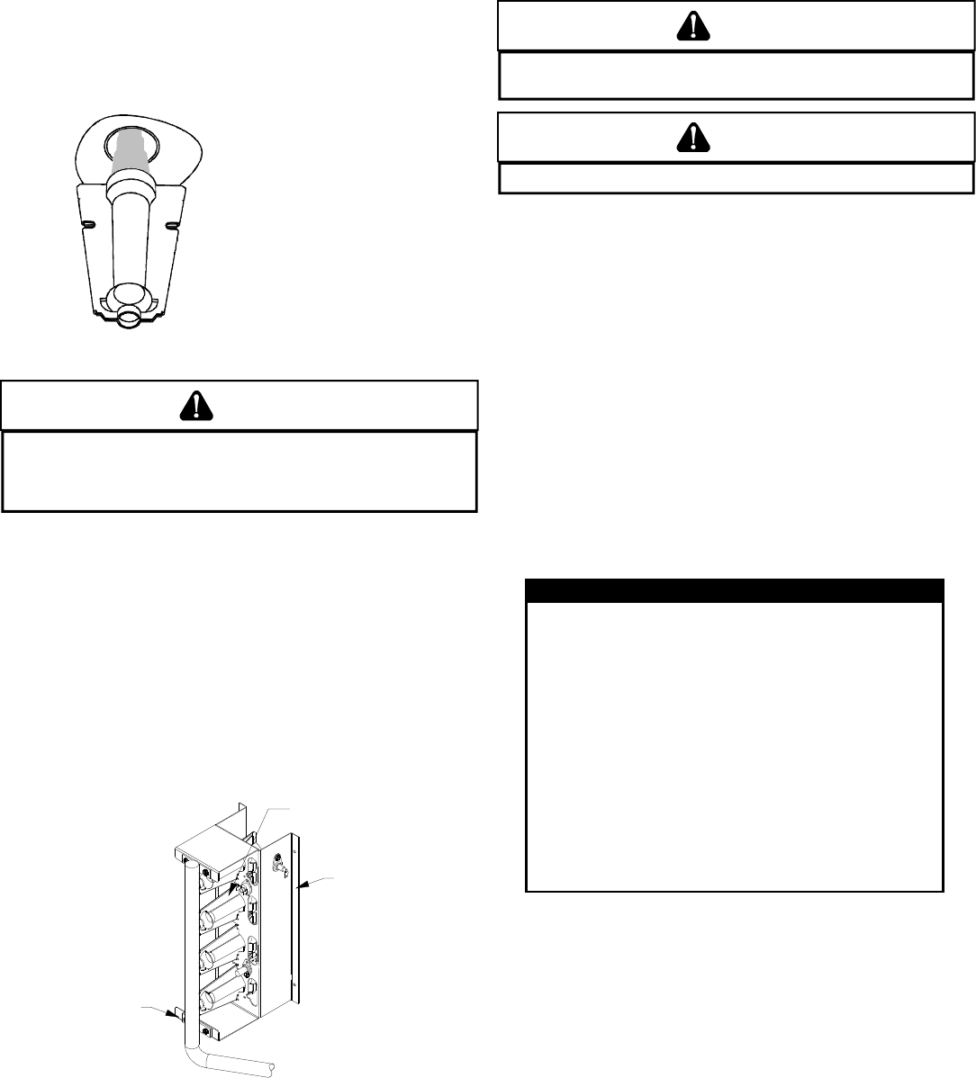
18
MAIN BURNER FLAME (QUALIFIED SERVICER ONLY)
Flames should be stable, soft and blue (dust may cause
orange tips but must not be yellow). The flames must extend
directly outward from the burner without curling, floating or
lifting off.
Check the burner flames for:
1. Good adjustment
2. Stable, soft and blue
3. Not curling, floating, or lifting off.
Burner Flame
WARNING
TO AVOID PERSONAL INJURY OR DEATH DUE TO ELECTRIC SHOCK,
DO NOT REMOVE ANY INTERNAL COMPARTMENT COVERS OR ATTEMPT ANY
ADJUSTMENT. CONTACT A QUALIFIED SERVICER AT ONCE IF AN ABNORMAL
FLAME SHOULD DEVELOP.
At least once a year, prior to or during the heating season,
make a visual check of the burner flames.
NOTE: This will involve removing and reinstalling the heat exchanger
door on the unit, which is held by two screws. If you are uncertain
about your ability to do this, contact a qualified servicer.
If a strong wind is blowing, it may alter the airflow pattern within the
unit enough that an inspection of the burner flames is not pos-
sible.
CLEANING B URNERS
1. Shut off electric power and gas supply to the unit.
2. Remove the screws securing the manifold to the burner
retention bracket. Remove the manifold and rotate each
burner counterclockwise to remove.
Burner
Bracket
Burner
Manifold
Manifold Assembly
3. Remove the burners.
4. Use a bottle brush to clean burner insert and inside of the
burners.
5. Replace burners and manifold, inspect the burner
assembly for proper seating of burners in retention slots.
6. Reconnect electrical power and gas supply.
CAUTION
LABEL ALL WIRES PRIOR TO DISCONNECTION WHEN SERVICING CONTROLS.
WIRING ERRORS CAN CAUSE IMPROPER AND DANGEROUS OPERATION.
CAUTION
ALWAYS VERIFY PROPER OPERATION AFTER SERVICING.
For further information on the yearly inspection, consult the
User Manual. It is recommended that a qualified servicer inspect
and service the unit at least once each year.
Turn the unit on at the thermostat. Wait a few minutes, since
any dislodged dust will alter the normal flame appearance.
Flames should be predominantly blue and directed into the
tubes. They should not be yellow. They should extend directly
outward from the burner ports without curling downward,
floating or lifting off the ports.
ACCESSORIES AND FUNCTIONAL PARTS
SHEET M ETAL A CCESSORIES
Additional accessories can be purchased to fit specific application
needs. Parts and instructions are available from your distributor.
FUNCTIONAL P ARTS
Auxliary Limit Switch Flame Roll-out Switch
Blower Housing Flame Sensor
Circulator Blower Motor Gas Orifice
Blower Wheel Gas Valve
Burner Heat Exchanger
Capacitor High Limit Switch
Compressor Igniter
Condenser Coil Ignition Control
Condenser Fan Blade Induced Draft Blower
Condenser Fan Motor Pressure Switch
Contactor Pressure Switch Hose
Gas Manifold Transformer
Evaporator Coil
FUNCTIONAL PARTS
Functional Parts List
GENERAL I NFORMATION
1. Refer to the description in Functional Parts List when
ordering any of the listed functional parts. Be sure to provide
the unit model and serial numbers with the order.
2. Although only functional parts are shown, all sheet metal
parts, doors, etc. may be ordered by description.
3. Parts are available from your distributor.
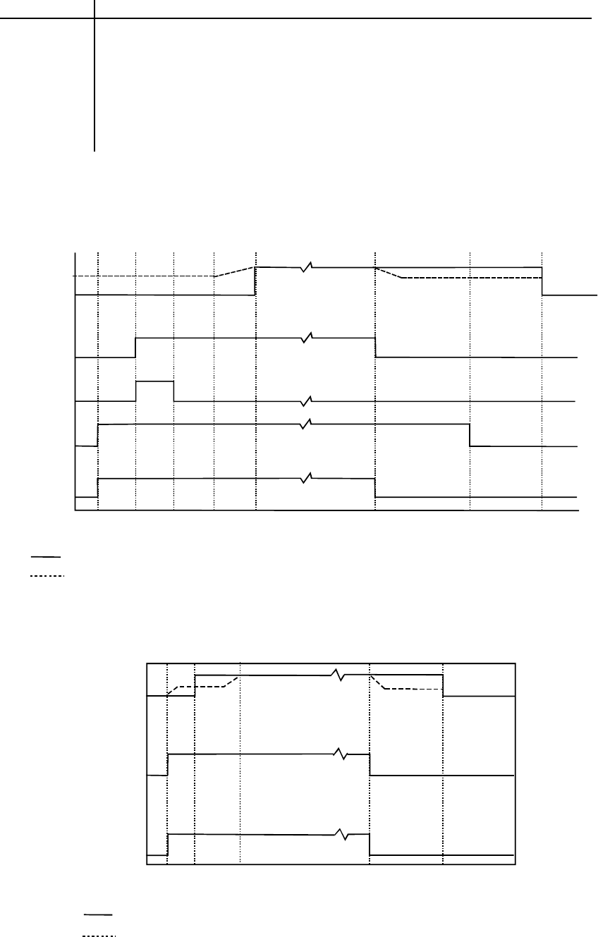
19
IGNITION CONTROL DIAGNOSTIC INDICATOR CHART
HEATING TIMING CHART
0 15 22 45 52 0 29 120, 135,150
180*PG1348,60 ONLY
Circulator
Blower
On
Off
Seconds
Gas Valve
Igniter
Induced
Draft
Blower
Thermostat
On
Off
On
Off
On
Off
On
Off
Legend: *PG10,12,24-60, *PG1324-42
*PG1348,60
100 %
50 %
COOLING TIMING CHART
Seconds 0 7 30 0 60
Circulator
Blower
Outdoor Fan
and
Compressor
Thermostat
ON
OFF
ON
OFF
ON
OFF
Legend: *PG10,12,24-60, *PG1324-42
*PG1348,60
100 %
50 %
Light Signal Refer to Abnormal Heating or Cooling Operation Sections of this Manual
Off Internal Control Failure
1 Flash External Lockout
2 Flashes Pressure Switch Stuck Open
3 Flashes Pressure Switch Stuck Closed
4 Flashes Thermal Protection Device Open
5 Flashes Flame Detected with Gas Valve Closed
6 Flashes Short Cycle Compressor Delay (Cooling Only)
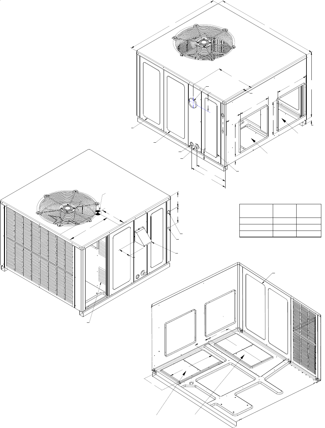
20
APPENDIX
UNIT DIMENSIONS
COMBUSTION AIR INLETS
HOOD FLUE EXHAUST
CONTROL WIRE ENTRANCE
POWER WIRE ENTRANCE
7 7/8
7 5/16
SUCTION/LIQUID PRESSURE PORTS
BEHIND COMPRESSOR ACCESS PANEL
HEAT EXCHANGE ACCESS PANEL
GAS SUPPLY ENTRANCE
CONDENSATE DRAIN CONNECTION
3/4" NPT FEMALE
16 1/8
19 1/8
EVAPORATOR/CONTROL PANEL ACCESS PANE
L
4 3/4
B
7 15/16
16
B
5 1/2
1 3/8
16
2 3/4
A
18 7/16
FLUE EXHAUST
51
47
BLOWER ACCESS PANEL
22
22
11
DIMENSION
(INCHES) SMALL MEDIUM LARGE
A27 32 40
B16 16 18
11
3SUPPLY
RETURN
SUPPLY RETURN
5 3/4
5 1/4
C
20
24 C 7 1/2 9 1/2 14
CENTER OF
GRAVITY
DIMENSION
INCHES MEDIUM LARGE
A3240
B1618
C9 1/214
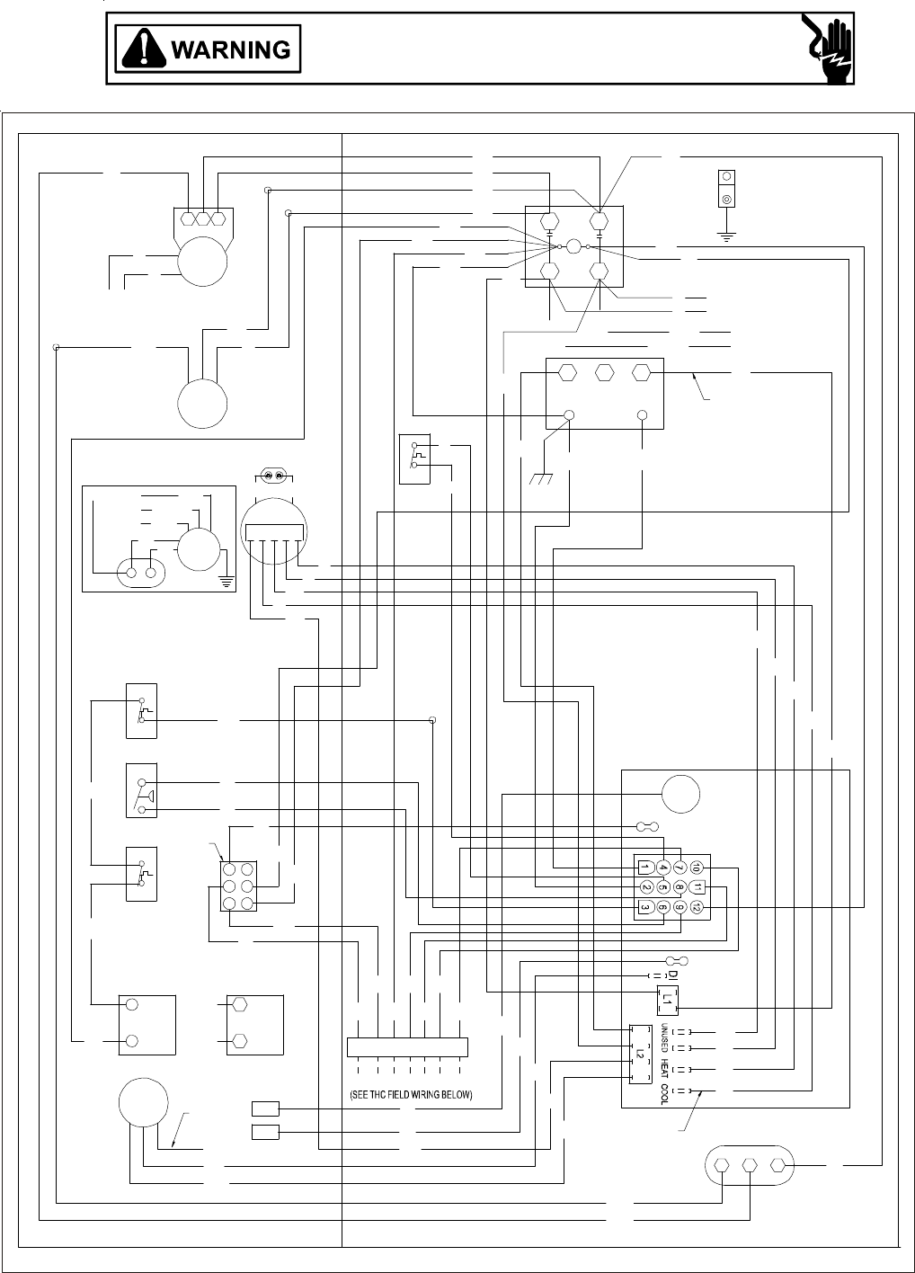
21
P
GPG13(24,30,36,42)1A WIRING DIAGRAM
TO THC
MOTOR
A
LT. 3 SPEED
PU
O
R
BL
Y
R
B
B
R
ECON
PU
R
PU
IIC
GRD
POWER SUPPLY
R
Y
Y
B
B
T2
L2
CC
R
T1
L1
CH OPTIONAL
208-230/1/60
B
3
NOTE 2
208
2
C
1
24V
BL
TRANS
240
GR
B
PU
R
BL
BL
BL B
BL
B
Y
PU
RCS
COMP
B
B
PU
PU
R
R
LS
B
BR
CM
BR
BR
EM
4 5
Y
123
LOW
R
BL MEDIUM
OPTIONAL
3 SPEED
EM
CAP.2
BR
PU
BHIGH
CAP2
NOTE 5
R
PU(L2)
CH OPTIONAL
CONNECTED AT L1, L2
NOTE 4
B
BL
Y
R
FS
R
O
R
HCF
Y
BR
CAP1
BL
B
PU
4 SPEED
MOTOR
ALS
Y
Y
PS
PU
W
G
GW
R
BL YY
PU
RCYY2 Y1
Y
BL
6
52
3
G
41
Y
PU
PL
RS
MV
GAS VALVE
MV
GV
PU
W. R.
BL
GV
(
ALT.
)
HONEYWELL
NOTE 6
PU
PU
BL
GAS VALVE
FS
IGN
VM
B
R
PU
NOTE 3
NOTE 5
B4312003 REV. B
Wiring is subject to change. Always refer to the wiring diagram on the unit for the most up-to-date wiring.
HIGH VOLTAGE!
DISCONNECT ALL POWER BEFORE SERVICING OR INSTALLING THIS
UNIT. MULTIPLE POWER SOURCES MAY BE PRESENT. FAILURE TO
DO SO MAY CAUSE PROPERTY DAMAGE, PERSONAL INJURY OR DEATH.
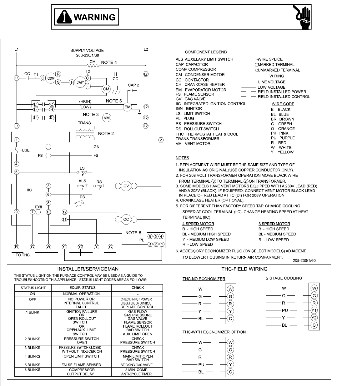
22
GPG13(24,30,36,42)1A WIRING DIAGRAM
HIGH VOLTAGE!
DISCONNECT ALL POWER BEFORE SERVICING OR INSTALLING THIS
UNIT. MULTIPLE POWER SOURCES MAY BE PRESENT. FAILURE TO
DO SO MAY CAUSE PROPERTY DAMAGE, PERSONAL INJURY OR DEATH.
B4312003 REV. B
Wiring is subject to change. Always refer to the wiring diagram on the unit for the most up-to-date wiring.
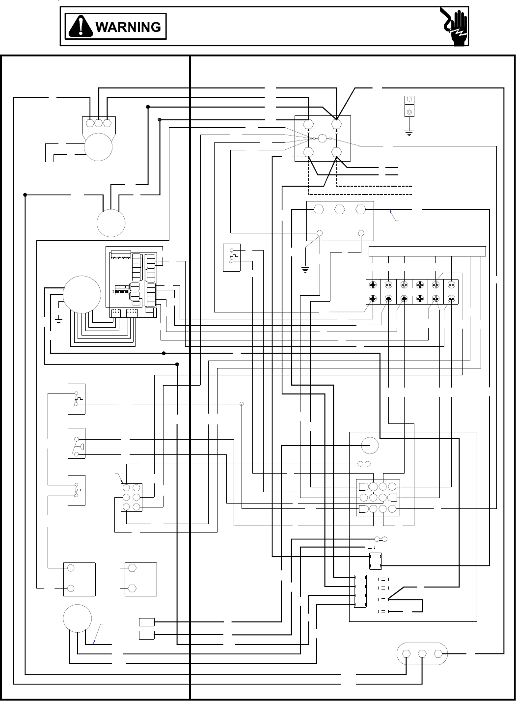
23
Y
W
IGN
VM
PU
FS
NOTE 3
B
R
W. R. (ALT.) HONEYWELL
BL
GAS VALVE
GV
BL MV
GAS VALVE
GV
PU MV
PU
RS
Y
PU
PL Y
BL
NOTE 5
PS
PU
Y
Y
G
PU
PU
ALS
B
Y
PU
O
R
PU
BR
Y
PU CAP1
R
R
L1 UNUSED HEAT COOL
6
45
O
R
R
L2
PU
3
Y
Y
R
12
DI
B
B
Y
12
9
R
FS
10
7
11
8
ECON
YPU BL
R
B
G
YW
RY
RG YW
GW
B
Y
G
BL
TH ER M OST AT
HEATER
W1
HUM
OFF
ON
DIP SWITCH
Y1
RC
24 VAC
W2
R
G
HUMIDISTAT
Y1/Y2GY1R
C
HEATPUMP
CO NDENSER
OUTD OOR
EDW2O
COMYCON
R
W
E/W1W/W2O OTCOT1OT2
BR
CM
PU
B
Y
COMP
B
B
S CR
CH OPTIONAL
BL
C
LS
R
R
BL
BL
PU BL R
PU
R
R
G
G
Y
W
PU
Y1
Y
208-230/1/60
POWER SUPPLY
B
NOTE 2
B
B
BL
BL
BL
BL
B
PU
L1
B
R
CC L2
T1 T2
R
B
Y
GRD
R
Y
RY2
CH OPTIONAL
CONNECTED AT L1, L2
NOTE 4
(SEE THC FIELD WIRING BELOW)
TO THC
41
3
2
6
5
FCH
VSM
6578312 4
VSTB
123
TRANS
C
24V
208 240
TB
IIC
B4312004 Rev. A
GPG13(48)1A WIRING DIAGRAM
HIGH VOLTAGE!
DISCONNECT ALL POWER BEFORE SERVICING OR INSTALLING THIS
UNIT. MULTIPLE POWER SOURCES MAY BE PRESENT. FAILURE TO
DO SO MAY CAUSE PROPERTY DAMAGE, PERSONAL INJURY OR DEATH.
Wiring is subject to change. Always refer to the wiring diagram on the unit for the most up-to-date wiring.
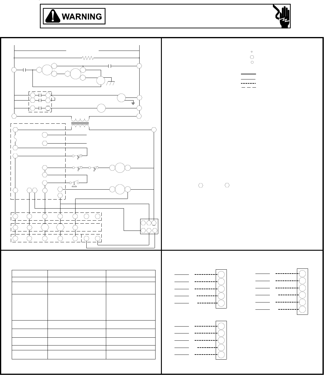
24
NOTE 6
WW
Y
Y
BL C
W
G
R
W
G
R
PU
BL
Y
G
R
Y1
C
Y2
G
R
THC-NO ECONOMIZER
NOTE 5
PL
NOTE 3
NOTE 2
NOTE 5
NOTE 4
2 STAGE COOLING
THC-WITH ECONOMIZER OPTION
BL
PU
C
Y1
R
G
W
R
G
W
PS
TROUBLESHOOTING THIS APPLIANCE. STATUS LIGHT CODES ARE AS FOLLOWS:
THE STATUS LIGHT ON THE FURNACE CONTROL MAY BE USED AS A GUIDE TO
CC
STICKING GAS VALVE
STATUS LIGHT EQUIP. STATUS
FALSE FLAME SENSED
OPEN LIMIT SWITCH
6 BLINKS
5 BLINKS
3 BLINKS
2 BLINKS
4 BLINKS
NORMAL OPERATION
1 BLINK
OFF
ON
VSTB
TB
INSTALLER/SERVICEMAN
TO THC
R
R
G
G
W/W2
W
Y/Y2
Y1
C
G
RW
ECON
9710
8
12
11
CY1
CHECK
-
B4312004 Rev. A
THC-FIELD WIRING
4. CRANKCASE HEATER (OPTIONAL).
231
56 4
208-230/1/60
GV
VSM
1
5
IIC 6
3
FS
FUSE
4
RS
ALS
LS
FS
IGN
L1
L1 D1
L1
L1
H
C
TRANS
VM
CC
L1 T1 CCOMP
R
S
L1
CAP1
HC
F
T2
CC
CM
SUPPLY VOLTAGE
208-230/1/60
CH
FIELD INSTALLED POWER
VSTB VARIABLE SPEED TERM. BLOCK
IIC INTEGRATED IGNITION CONTROL
THC THERMOSTAT HEAT & COOL
2
NOTES
TB TERMINAL BLOCK
VSM VAR. SPEED MOTOR
TRANS TRANSFORMER
RS ROLLOUT SWITCH
VM VENT MOTOR
PS PRESSURE SWITCH
IGN IGNITOR
GV GAS VALVE
LS LIMIT SWITCH
PL PLUG
L2
L2
L2
R RED
Y YELLOW
W WHITE
FIELD INSTALLED CONTROL
BL BLUE
PK PINK
PU PURPLE
G GREEN
O ORANGE
BR BROWN
WIRE CODE
B BLACK
ALS AUXILLARY LIMIT SWITCH
COMP COMPRESSOR
CM CONDENSER MOTOR
CC CONTACTOR
CH CRANKCASE HEATER
FS FLAME SENSOR
COMPONENT LEGEND
CAP CAPACITOR
L2
L2
MARKED TERMINAL
LINE VOLTAGE
LOW VOLTAGE
UNMARKED TERMINAL
WIRING
WIRE SPLICE
Y
Y
CY2
Y2
1. REPLACEMENT WIRE MUST BE THE SAME SIZE AND TYPE OF
INSULATION AS ORIGINAL.(USE COPPER CONDUCTOR ONLY).
2. FOR 208 VOLT TRANSFORMER OPERATION MOVE BLACK WIRE
FROM TERMINAL 3 TO TERMINAL 2 ON TRANSFORMER.
3. SOME MODELS HAVE VENT MOTORS EQUIPPED WITH A 230V LEAD (RED)
AND A 208V (BLACK). IF EQUIPPED, CONNECT VENT MOTOR BLACK LEAD IN
PLACE OF RED LEAD AT UII (DI) FOR 208V OPERATION.
5. ACCESSORY ECONOMIZER PLUG (ON SELECT MODELS) ADJACENT
TO BLOWER HOUSING IN RETURN AIR COMPARMENT.
6. TWO STAGE THERMOSTAT CONNECTIONS IF USED WITH ECONOMIZER
OPTION INSTALLED.
NO POWER OR
INTERNAL CONTROL
FAULT
IGNITION FAILURE
OR
OPEN ROLLOUT
SWITCH
OR
OPEN AUX. LIMIT
SWITCH
PRESSURE SWITCH
OPEN
PRESSURE SWITCH CLOSED
WITHOUT INDUCER ON
COMPRESSOR
OUTPUT DELAY
CHECK INPUT POWER
CHECK FUSE ON CONTROL
REPLACE CONTROL
GAS FLOW
GAS PRESSURE
GAS VALVE
FLAME SENSOR
FLAME ROLLOUT
BAD SWITCH
AUX. LIMIT OPEN
CHECK
PRESSURE SWITCH
CHECK
PRESSURE SWITCH
MAIN LIMIT OPEN
BAD SWITCH
3 MIN. COMP.
ANTI-CYCLE TIMER
GPG13(48)1A WIRING DIAGRAM
HIGH VOLTAGE!
DISCONNECT ALL POWER BEFORE SERVICING OR INSTALLING THIS
UNIT. MULTIPLE POWER SOURCES MAY BE PRESENT. FAILURE TO
DO SO MAY CAUSE PROPERTY DAMAGE, PERSONAL INJURY OR DEATH.
Wiring is subject to change. Always refer to the wiring diagram on the unit for the most up-to-date wiring.
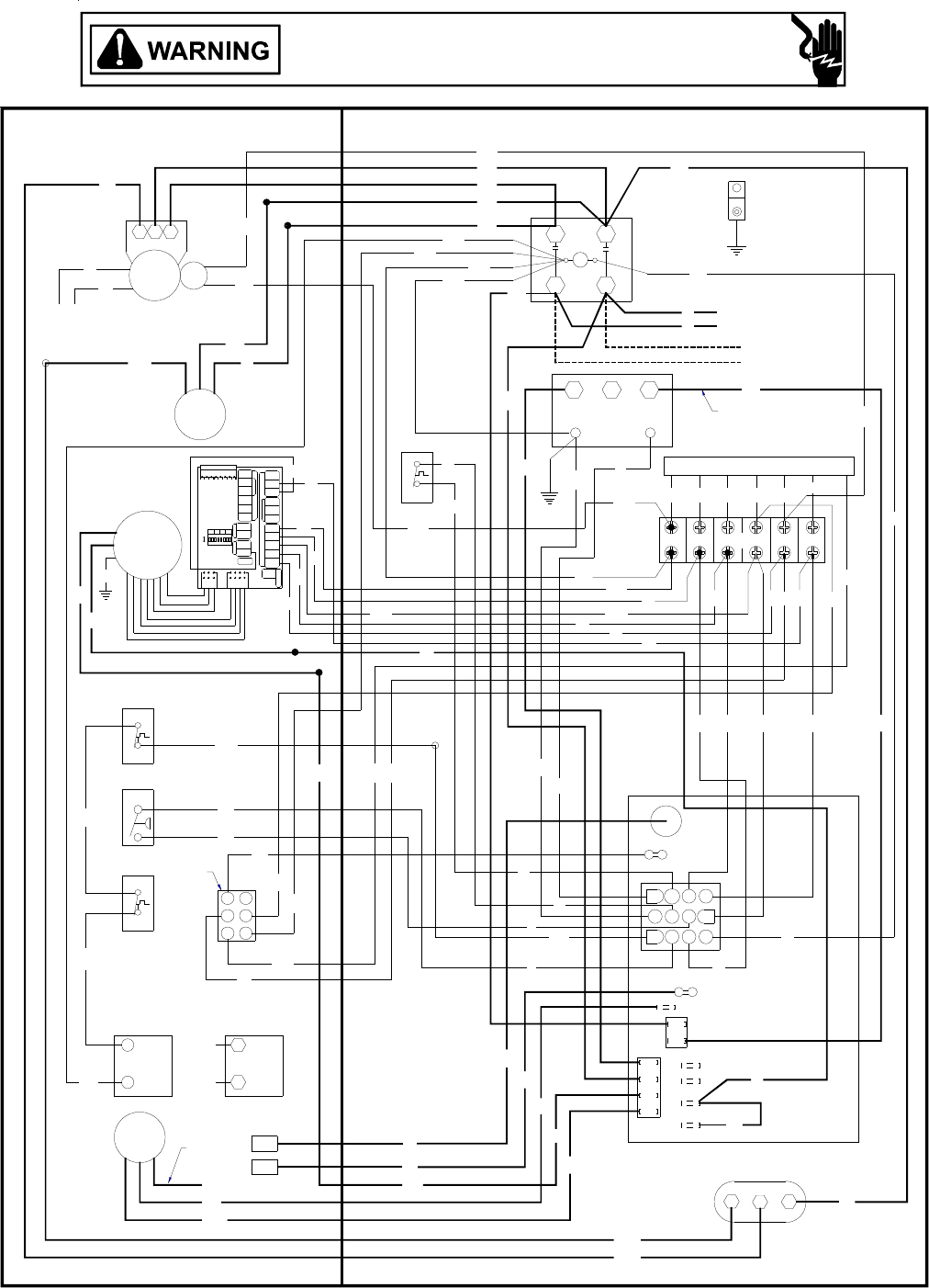
25
Y
W
IGN
VM
PU
FS
NOTE 3
B
R
W. R. (ALT.) HONEYWELL
BL
GAS VALVE
GV
BL MV
GAS VALVE
GV
PU MV
PU
RS
Y
PU
PL Y
BL
NOTE 5
PS
PU
Y
Y
G
PU
PU
ALS
B
Y
PU
O
R
PU
BR
Y
PU CAP1
R
R
L1 UNUSED HEAT COOL
6
45
O
R
R
L2
PU
3
Y
Y
R
12
DI
B
B
Y
12
9
R
FS
10
7
11
8
ECON
YPU BL
R
B
GYW
RY
RGYW
GW
B
Y
G
BL
TH ER MOS T AT
HEATER
W1
HUM
OFF
ON
DIP S WITCH
Y1
RC
24 VAC
W2
R
G
HUMIDISTAT
Y1/Y2GY1R
C
HEATPUMP
CONDENSER
OUT D OO R
EDW2O
COMYCON
R
W
E/W1W/W2 O OT C O T1 OT2
BR
CM
PU
B
Y
COMP
B
B
S C
R
CH OPTIONAL
BL
C
LS
R
R
BL
BL
PU BL R
PU
R
R
G
G
Y
Y/Y2 W
PU
Y1
Y
208-230/1/60
POWER SUPPLY
B
NOTE 2
B
B
BL
BL
BL
BL
B
PU
L1
B
R
CC L2
T1 T2
R
B
Y
GRD
R
Y1
PU PU
BL
BL
BL
PU
Y
Y
Y
W
SOL
R
CH OPTIONAL
CONNECTED AT L1, L2
NOTE 4
(SEE THC FIELD WIRING BELOW)
TO THC
41
3
2
6
5
FCH
VSM
6578312 4
VSTB
123
TRANS
C
24V
208 240
TB
IIC
B4312005 Rev. A
GPG13(60)1A WIRING DIAGRAM
HIGH VOLTAGE!
DISCONNECT ALL POWER BEFORE SERVICING OR INSTALLING THIS
UNIT. MULTIPLE POWER SOURCES MAY BE PRESENT. FAILURE TO
DO SO MAY CAUSE PROPERTY DAMAGE, PERSONAL INJURY OR DEATH.
Wiring is subject to change. Always refer to the wiring diagram on the unit for the most up-to-date wiring.
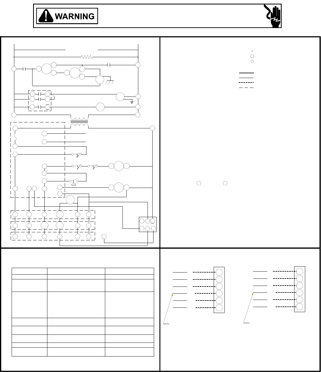
26
NOTE 6
WW
Y1
PU
YY2
W
G
R
W
G
R
PU
BL
Y
G
R
Y1
C
Y2
G
R
THC-NO ECONOMIZER
NOTE 5
PL
NOTE 3
NOTE 2
NOTE 5
NOTE 4
THC-WITH ECONOMIZER
BL C
STRIPPED LEAD
FROM TERMINAL BLOCK FROM ECON. PLUG
STRIPPED LEAD
PS
TROUBLESHOOTING THIS APPLIANCE. STATUS LIGHT CODES ARE AS FOLLOWS:
THE STATUS LIGHT ON THE FURNACE CONTROL MAY BE USED AS A GUIDE TO
CC
STICKING GAS VALVE
STATUS LIGHT EQUIP. STATUS
FALSE FLAME SENSED
OPEN LIMIT SWITCH
6 BLINKS
5 BLINKS
3 BLINKS
2 BLINKS
4 BLINKS
NORMAL OPERATION
1 BLINK
OFF
ON
VSTB
TB
INSTALLER/SERVICEMAN
TO THC
R
R
G
G
W/W2
W
Y/Y2
Y1
C
CY1
GRW
ECON
9710
8
12
11
CY1
CHECK
-
B4312005 Rev. A
THC-FIELD WIRING
4. CRANKCASE HEATER (OPTIONAL).
231
56 4
208-230/1/60
GV
VSM
1
5
IIC 6
3
FS
FUSE
4
RS
ALS
LS
FS
IGN
L1
L1 D1
L1
L1
H
C
TRANS
VM
CC
L1 T1 CCOMP
R
S
L1
CAP1HC
F
T2
CC
CM
SUPPLY VOLTAGE
208-230/1/60
CH
FIELD INSTALLED POWER
VSTB VARIABLE SPEED TERM. BLOCK
IIC INTEGRATED IGNITION CONTROL
THC THERMOSTAT HEAT & COOL
2
NOTES
TB TERMINAL BLOCK
VSM VAR. SPEED MOTOR
TRANS TRANSFORMER
RS ROLLOUT SWITCH
VM VENT MOTOR
PS PRESSURE SWITCH
IGN IGNITOR
GV GAS VALVE
LS LIMIT SWITCH
PL PLUG
L2
L2
L2
R RED
Y YELLOW
W WHITE
FIELD INSTALLED CONTROL
BL BLUE
PK PINK
PU PURPLE
G GREEN
O ORANGE
BR BROWN
WIRE CODE
B BLACK
ALS AUXILLARY LIMIT SWITCH
COMP COMPRESSOR
CM CONDENSER MOTOR
CC CONTACTOR
CH CRANKCASE HEATER
FS FLAME SENSOR
COMPONENT LEGEND
CAP CAPACITOR
L2
L2
MARKED TERMINAL
LINE VOLTAGE
LOW VOLTAGE
UNMARKED TERMINAL
WIRING
WIRE SPLICE
SOL SOLENOID (2 STAGE)
nd
Y1
SOL
Y/Y2
Y2
1. REPLACEMENT WIRE MUST BE THE SAME SIZE AND TYPE OF
INSULATION AS ORIGINAL.(USE COPPER CONDUCTOR ONLY).
2. FOR 208 VOLT TRANSFORMER OPERATION MOVE BLACK WIRE
FROM TERMINAL 3 TO TERMINAL 2 ON TRANSFORMER.
3. SOME MODELS HAVE VENT MOTORS EQUIPPED WITH A 230V LEAD (RED)
AND A 208V LEAD (BLACK). IF EQUIPPED, CONNECT VENT MOTOR BLACK
LEAD IN PLACE OF RED LEAD AT UII (D1) FOR 208V OPERATION.
5. ACCESSORY ECONOMIZER PLUG (ON SELECT MODELS) ADJACENT
TO BLOWER HOUSING IN RETURN AIR COMPARMENT.
6. TWO STAGE THERMOSTAT CONNECTIONS IF USED WITH ECONOMIZER
OPTION INSTALLED.
NO POWER OR
INTERNAL CONTROL
FAULT
IGNITION FAILURE
OR
OPEN ROLLOUT
SWITCH
OR
OPEN AUX. LIMIT
SWITCH
PRESSURE SWITCH
OPEN
PRESSURE SWITCH CLOSED
WITHOUT INDUCER ON
COMPRESSOR
OUTPUT DELAY 3 MIN. COMP.
ANTI-CYCLE TIMER
MAIN LIMIT OPEN
BAD SWITCH
CHECK
PRESSURE SWITCH
CHECK
PRESSURE SWITCH
GAS FLOW
GAS PRESSURE
GAS VALVE
FLAME SENSOR
FLAME ROLLOUT
BAD SWITCH
AUX. LIMIT OPEN
CHECK INPUT POWER
CHECK FUSE ON CONTROL
REPLACE CONTROL
GPG13(60)1A WIRING DIAGRAM
HIGH VOLTAGE!
DISCONNECT ALL POWER BEFORE SERVICING OR INSTALLING THIS
UNIT. MULTIPLE POWER SOURCES MAY BE PRESENT. FAILURE TO
DO SO MAY CAUSE PROPERTY DAMAGE, PERSONAL INJURY OR DEATH.
Wiring is subject to change. Always refer to the wiring diagram on the unit for the most up-to-date wiring.
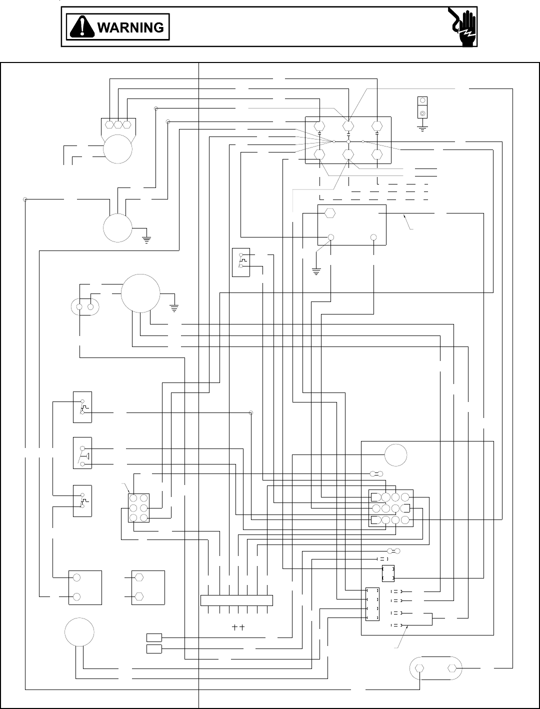
27
GPG13(36)3A WIRING DIAGRAM
MV
MV
RS
PS
ALS
MOTOR
10
7
4
1
11 12
89
2
56
3
DI L1 COOLHEATUNUSED
L2
LS
T3 T1T2
L1
T1
L2
T2 T3
L3
3 SPEED
PU
RD
IGN
FS
BL
PU
PU
BL
PU
PU
YL
GR
BL
YL
PU
YL YLBL
RD
GR
WH
PU
YL
YL
PU BL
BK
BR
RD
OR
RD
FS
RD
BK
BL
RD
BR BK
RD
RD PU
PU
BK
BK
PU
BK
BL
BK
BL
BL
BL
RD
PU BK
BL
BK
BK
BK
YL YL
RD
RD
PU
ECON
RD
BK
BL
RD
BK
RD
OR
YL
PU BR
BK
PU
PU
PU
BLBR
14
3
25
6
FC
240
24V
1
C
2
208
3
NOTE 4
GAS VALVE
NOTE 5
(ALT.) HONEYWELLW. R.
GAS VALVE
PLF
Y1Y2 YCR WG
CH OPTIONAL
CONNECTED AT L1, L2
NOTE 3
NOTE 4
NOTE 2
208-230/3/60
CH OPTIONAL
POWER SUPPLY
GND
TO THERMOSTAT
SEE NOTE 3
SEE NOTE 6
VM
GV GV
FC
EM
CM
COMP
TR
C
IIC
FC
HIGH VOLTAGE!
DISCONNECT ALL POWER BEFORE SERVICING OR INSTALLING THIS
UNIT. MULTIPLE POWER SOURCES MAY BE PRESENT. FAILURE TO
DO SO MAY CAUSE PROPERTY DAMAGE, PERSONAL INJURY OR DEATH.
Wiring is subject to change. Always refer to the wiring diagram on the unit for the most up-to-date wiring.
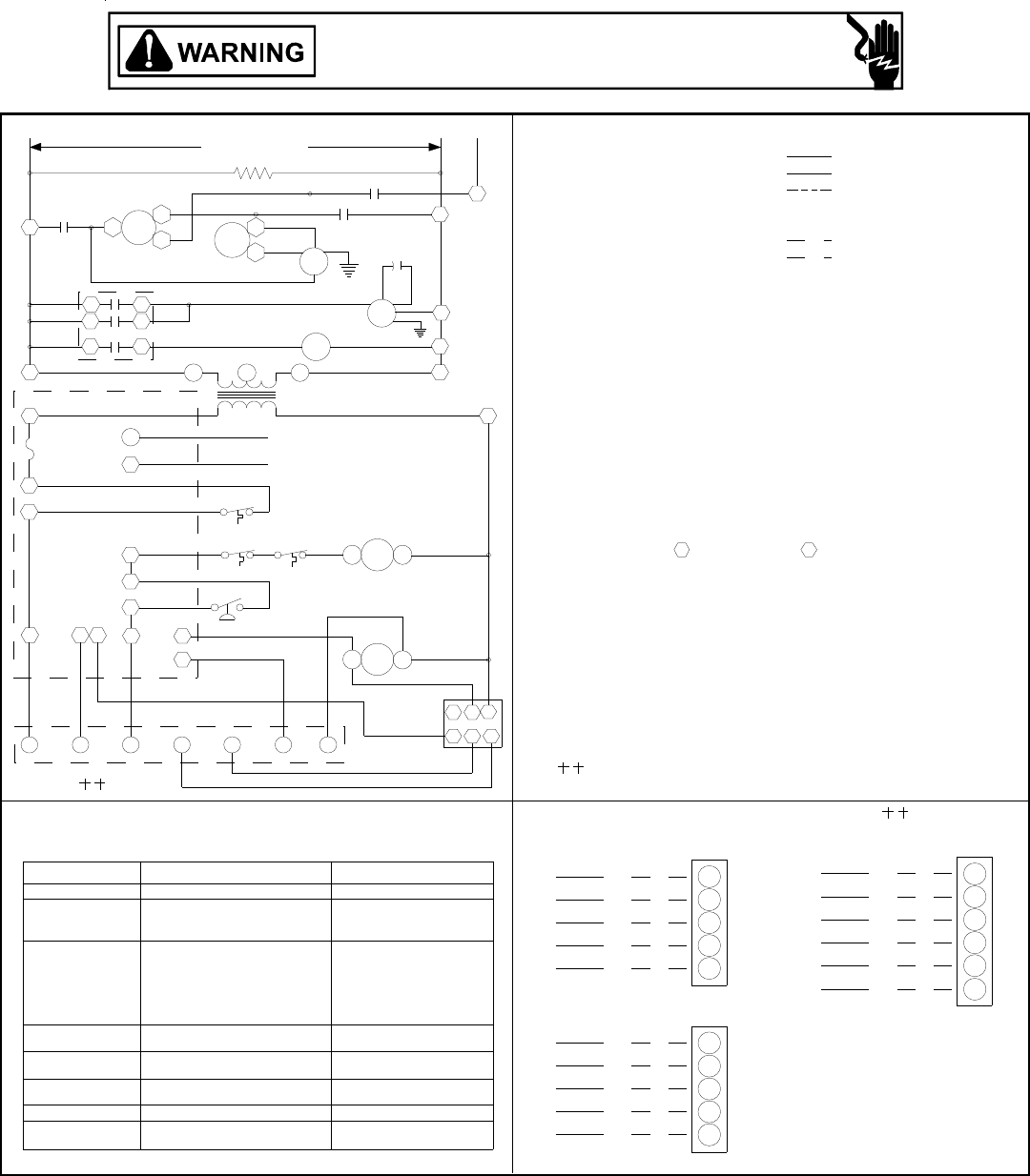
28
GPG13(36)3A WIRING DIAGRAM
Wiring is subject to change. Always refer to the wiring diagram on the unit for the most up-to-date wiring.
HIGH VOLTAGE!
DISCONNECT ALL POWER BEFORE SERVICING OR INSTALLING THIS
UNIT. MULTIPLE POWER SOURCES MAY BE PRESENT. FAILURE TO
DO SO MAY CAUSE PROPERTY DAMAGE, PERSONAL INJURY OR DEATH.
FROM TERMINAL 3 TO TERMINAL 2 ON TRANSFORMER.
NOTE 5
NOTE 4
NOTE 2
NOTE 3
NO ECONOMIZER
WH W
G
GR
RD R
YL Y
BL
BL C
PU Y
RD
GR
WH
G
R
W
WITH ECONOMIZER OPTION
C
R
RD
C
Y2
YL
BL
W
G
WH
GR
2 STAGE COOLING
Y1PU
TO THERMOSTAT
1. REPLACEMENT WIRE MUST BE THE SAME SIZE AND TYPE OF
3 BLINKS
6 BLINKS
2 BLINKS
STATUS LIGHT
4 BLINKS
5 BLINKS
INSULATION AS ORIGINAL.(USE COPPER CONDUCTOR ONLY).
3. CRANKCASE HEATER NOT SUPPLIED ON ALL UNITS.
2. FOR 208 VOLT TRANSFORMER OPERATION MOVE BLACK WIRE
1 BLINK
4. FOR DIFFERENT THAN FACTORY SPEED TAP. CHANGE COOLING
SPEED AT COOL TERMINAL (IIC). CHANGE HEATING SPEED AT HEAT
TERMINAL (IIC)
5. ACCESSORY ECONOMIZER PLUG (ON SELECT MODELS) ADJACENT
TO BLOWER HOUSING IN RETURN AIR COMPARMENT.
0140G00085P
INSTALLER/SERVICEMAN
TROUBLESHOOTING THIS APPLIANCE. STATUS LIGHT CODES ARE AS FOLLOWS:
THE STATUS LIGHT ON THE FURNACE CONTROL MAY BE USED AS A GUIDE TO
97
RG
IIC
ECON
5
10 12
Y2WY1
11
YC
PS
ALS
LS
8
6
3RS
PLF 65
23
C
1
4
GV
FALSE FLAME SENSED
OUTPUT DELAY
OPEN LIMIT SWITCH
COMPRESSOR
ANTI-CYCLE TIMER
MAIN LIMIT OPEN
STICKING GAS VALVE
BAD SWITCH
3 MIN. COMP.
WITHOUT INDUCER ON
PRESSURE SWITCH CLOSED
OR
PRESSURE SWITCH
OPEN AUX. LIMIT
OPEN ROLLOUT
SWITCH
OPEN
SWITCH
OR
EQUIP. STATUS
IGNITION FAILURE
NORMAL OPERATION
NO POWER OR
INTERNAL CONTROL
OFF
ON
FAULT
GAS PRESSURE
PRESSURE SWITCH
PRESSURE SWITCH
FLAME ROLLOUT
AUX. LIMIT OPEN
FLAME SENSOR
BAD SWITCH
GAS VALVE
CHECK
CHECK
CHECK FUSE ON CONTROL
CHECK INPUT POWER
REPLACE CONTROL
208-230/3/60
GAS FLOW
CHECK
-
RD - LOW SPEED
BK - HIGH SPEED
BL - MEDIUM SPEED
3 SPEED MOTOR
TRANSFORMER
FLAME SENSOR
IGNITOR
EVAPORATOR MOTOR
GAS VALVE
INTEGRATED IGNITION CONTROL
LIMIT SWITCH
FEMALE PLUG/CONNECTOR
ROLLOUT SWITCH
VENT MOTOR
AUXILLARY LIMIT SWITCH
COMPONENT LEGEND
COMPRESSOR
CONDENSER MOTOR
CONTACTOR
CRANKCASE HEATER
PRESSURE SWITCH
T1
CT1
F
4
FS
1
L1
L1
L1
L1
L1
L1
T2 L2
TR
FS
IGN
(MED)
FC
D1
H
C
COMP T3
VM
C
F
C
CM
L2
NOTES
2
EM L2
L2
FC
SUPPLY VOLTAGE
208-230/3/60
T2
CH
L2 FACTORY WIRING
YL YELLOW
OPTIONAL HIGH VOLTAGE
LINE VOLTAGE
LOW VOLTAGE
BR BROWN
RD RED
WH WHITE
PK PINK
PU PURPLE
GR GREEN
OR ORANGE
WIRE CODE
BK BLACK
BL BLUE
THERMOSTAT FIELD WIRING
L3
L3
321
C
T3
IIC
FIELD WIRING
HIGH VOLTAGE
LOW VOLTAGE
FUSE
FAN CAPACITOR
EQUIPMENT GROUND
ALS
COMP
CM
C
CH
EM
F
FC
FS
GND
GV
IIC
IGN
LS
PLF
PS
RS
TR
VM
6. USE COOPER CONDUCTORS ONLY.
USE NEC CLASS 2 WIRE.
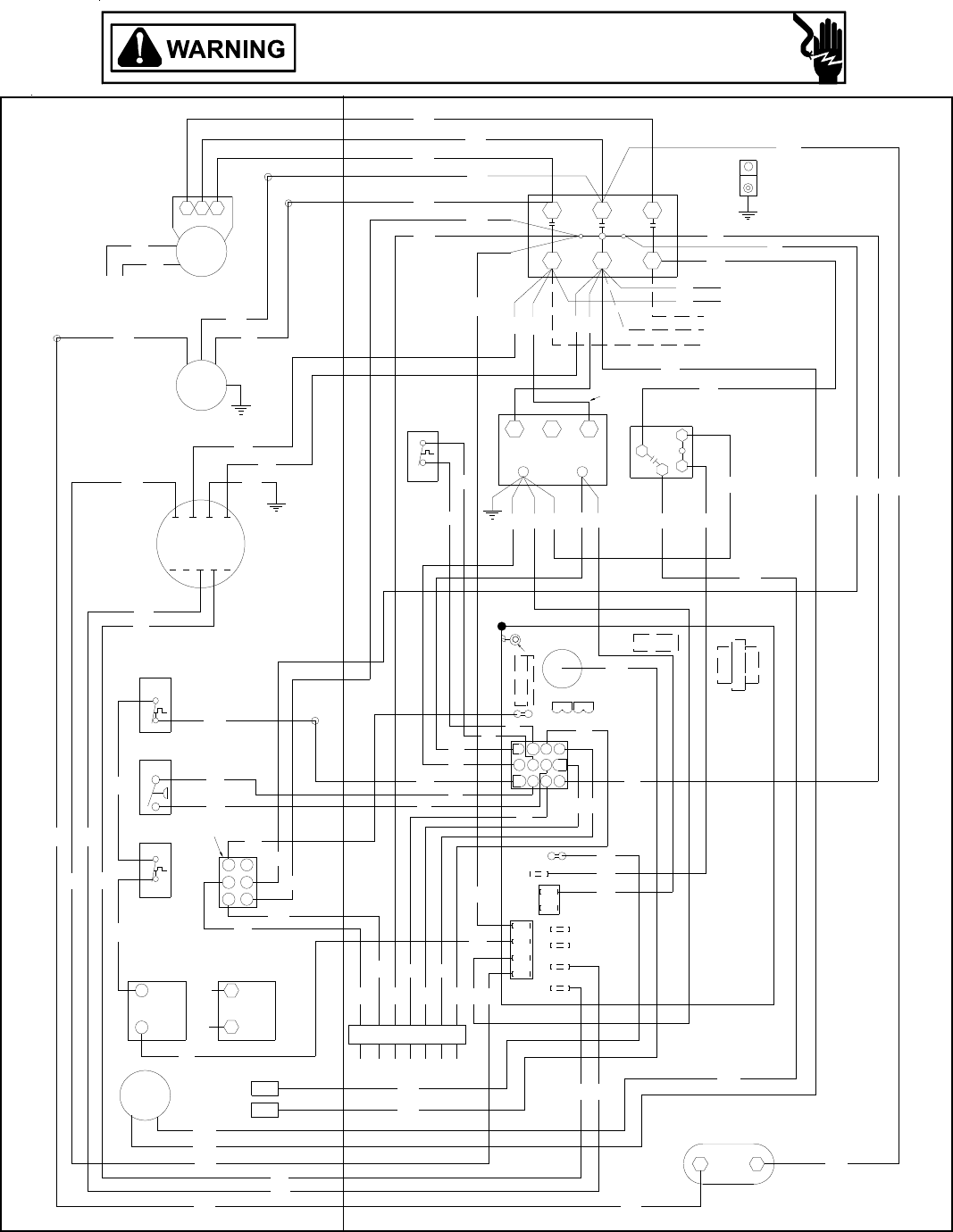
29
GPG13(48,60)3A WIRING DIAGRAM
RD
BL YL
WH
GR
YL
YL WH
YL
RD
GR
YL
BL
RD
RD
BK
PU
BR
PU
BL
BK RD
PU
BK
PU
BK
YL
BL
PU
PU
YL
YL
RD
RD
RD
PU
BR
BL
PU
BL
YL
PU
GR
PU
YL
BL
YL
BK BK
BK
BK
YL
YL
BL BL RD
RD
OR
RD
WH
RD
BL
PU
RD
BK PU
RD
RD
RD
BL
BL
BL
BL
OR
RD
WH
BK
BK
BR
BR
BK
PU
PU
BL
RD
PU YL
BL
BL
BL
YL
WH
BL
WH
YL
YL
GR RD
YL
YL
WH
WH RD
TO THERMOSTAT
RC G
YW
SPEED-UP
BREAK FOR TWO STAGE
T2
C22
MOUNT
T1
P2
REQUIRED
SCREW
COOL
COMPRESSOR
P3
FUSE 3 AMP MAX
F1
P1
135
ECON
120
150
11
8
12
97
10
4
2
56
3
1DI
L1
FS HEAT
UNUSED
L2
GND
POWER SUPPLY
208-230/3/60
CH OPTIONAL
CONNECTED AT L1, L2
NOTE 3
Y1Y2
CH OPTIONAL
NOTE 5
PLF
T1 T2 T3 T4 T5
NOTE 4
NOTE 2
SEE NOTE 6
NOTE 7
SEE
CM
W. R.
GAS VALVE
MV
GV
GAS VALVE
(ALT.) HONEYWELL
MV
GV
PS
LS
ALS
L1 L2
C
T1 T2
T1
COMP
T3 T2
VM
RS
C
IIC
FC
FS
IGN
3
2
14
5
6
T3
L3
1
C
24V
2
TR
3
240 3
4
21
VMR
LGN
208
EM
Wiring is subject to change. Always refer to the wiring diagram on the unit for the most up-to-date wiring.
HIGH VOLTAGE!
DISCONNECT ALL POWER BEFORE SERVICING OR INSTALLING THIS
UNIT. MULTIPLE POWER SOURCES MAY BE PRESENT. FAILURE TO
DO SO MAY CAUSE PROPERTY DAMAGE, PERSONAL INJURY OR DEATH.
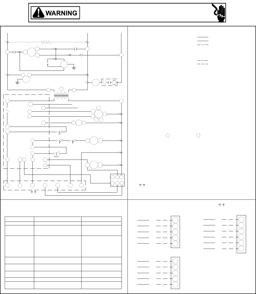
30
GPG13(48,60)3A WIRING DIAGRAM
NOTES
EVAPORATOR MOTOR
EM
RS ROLLOUT SWITCH
TRANSFORMERTR
FLAME SENSOR
INTEGRATED IGNITION CONTROL
LIMIT SWITCH
FEMALE PLUG/CONNECTOR
PRESSURE SWITCH
EQUIPMENT GROUND
IIC
IGN
LS
PLF
PS
IGNITOR
GND
FS
GV GAS VALVE
AUXILLARY LIMIT SWITCH
CONDENSER MOTOR
CONTACTOR
CRANKCASE HEATER
COMPONENT LEGEND
CM
C
CH
ALS
PU PURPLE
YL YELLOW
WH WHITE
RD RED
BL BLUE
BR BROWN
GR GREEN
OR ORANGE
PK PINK
WIRE CODE
BK BLACK
LOW VOLTAGE
LOW VOLTAGE
FIELD WIRING
HIGH VOLTAGE
OPTIONAL HIGH VOLTAGE
FACTORY WIRING
LINE VOLTAGE
COMP COMPRESSOR
VM VENT MOTOR
1. REPLACEMENT WIRE MUST BE THE SAME SIZE AND TYPE OF
INSULATION AS ORIGINAL.(USE COPPER CONDUCTOR ONLY).
2. FOR 208 VOLT TRANSFORMER OPERATION MOVE BLACK WIRE
FROM TERMINAL 3 TO TERMINAL 2 ON TRANSFORMER.
5. ACCESSORY ECONOMIZER PLUG (ON SELECT MODELS) ADJACENT
TO BLOWER HOUSING IN RETURN AIR COMPARMENT.
3. CRANKCASE HEATER NOT SUPPLIED ON ALL UNITS.
4. FOR DIFFERENT THAN FACTORY SPEED TAP. CHANGE COOLING
SPEED AT MOTOR T4 AND T5 TERMINALS. CHANGE HEATING
SPEED AT MOTOR T1, T2 AND T3 TERMINALS.
HEATING SPEED (WHITE WIRE)
T1 - LOW SPEED
7. L1 AND L2 ON ICC CONTROL IS 24V INPUT.
T2 - MED. SPEED
T3 - HIGH SPEED
T5 - HIGH SPEED
6. USE COOPER CONDUCTORS ONLY.
USE NEC CLASS 2 WIRE.
COOLING SPEED (YELLOW WIRE)
T4 - LOW SPEED
208-230/3/60
FFUSE
VMR VENT MOTOR RELAY
FC FAN CAPACITOR
WITH ECONOMIZER OPTION
WH
GR
RD
PU
BL
BL
YL
RD
GR
WH
NO ECONOMIZER
WH W
W
0140G00087
Y
C
W
R
G
Y
C
R
G
PU Y1
BL
YL Y2
C
GR
RD
G
R
THERMOSTAT FIELD WIRING
2 STAGE COOLING
NOTE 3
TR
NOTE
NOTE 7NOTE 7
SEE NOTE 2
5
EM
RGWY1
TO THERMOSTAT
11
Y2 Y
C
PLF
65
123
4
4
IIC
ECON
97
8
10 12
6
5
3
FS
F
L1
PS
ALS RS
LS
GV
FS
IGN
VM
L2
SUPPLY VOLTAGE
L1 T1 COMP
T3
CT1 T2
L1
C
FC CM
208-230/3/60
T2
CH
L2
L2
C
L3
L3
C
T3
D1
C
HC
13
EM
VMR
VMR
42
T4
T3
LN
321
IIC
T5
T1T2
CHECK
EQUIP. STATUS
STATUS LIGHT
FAULT
INTERNAL CONTROL
NO POWER OR
NORMAL OPERATION
IGNITION FAILURE
SWITCH
OPEN
SWITCH
OPEN ROLLOUT
OPEN AUX. LIMIT
PRESSURE SWITCH
PRESSURE SWITCH CLOSED
WITHOUT INDUCER ON
COMPRESSOR
OPEN LIMIT SWITCH
OUTPUT DELAY
FALSE FLAM E SENSED
5 BLINKS
4 BLINKS
2 BLINKS
6 BLINKS
3 BLINKS
1 BLINK
OR
OR
ON
OFF
CHECK
CHECK
PRESSURE SWITCH
PRESSURE SWITCH
3 MIN. COMP.
BAD SWITCH
STICKING GAS VALVE
MAIN LIMIT OPEN
ANTI-CYCLE TIMER
GAS FLOW
REPLACE CONTROL
CHECK IN PUT POWER
CHECK FUSE ON CONTROL
GAS VALVE
BAD SWITCH
FLAME SENSOR
AUX. LIMIT OPEN
FLAME ROLLOUT
GAS PRESSURE
-
THE STATUS LIGHT ON THE FURNACE CONTROL MAY BE USED AS A GUIDE TO
TROUBLESHOOTING THIS APPLIANCE. STATUS LIGHT CODES ARE AS FOLLOWS:
INSTALLER/SERVICEMAN
Wiring is subject to change. Always refer to the wiring diagram on the unit for the most up-to-date wiring.
HIGH VOLTAGE!
DISCONNECT ALL POWER BEFORE SERVICING OR INSTALLING THIS
UNIT. MULTIPLE POWER SOURCES MAY BE PRESENT. FAILURE TO
DO SO MAY CAUSE PROPERTY DAMAGE, PERSONAL INJURY OR DEATH.
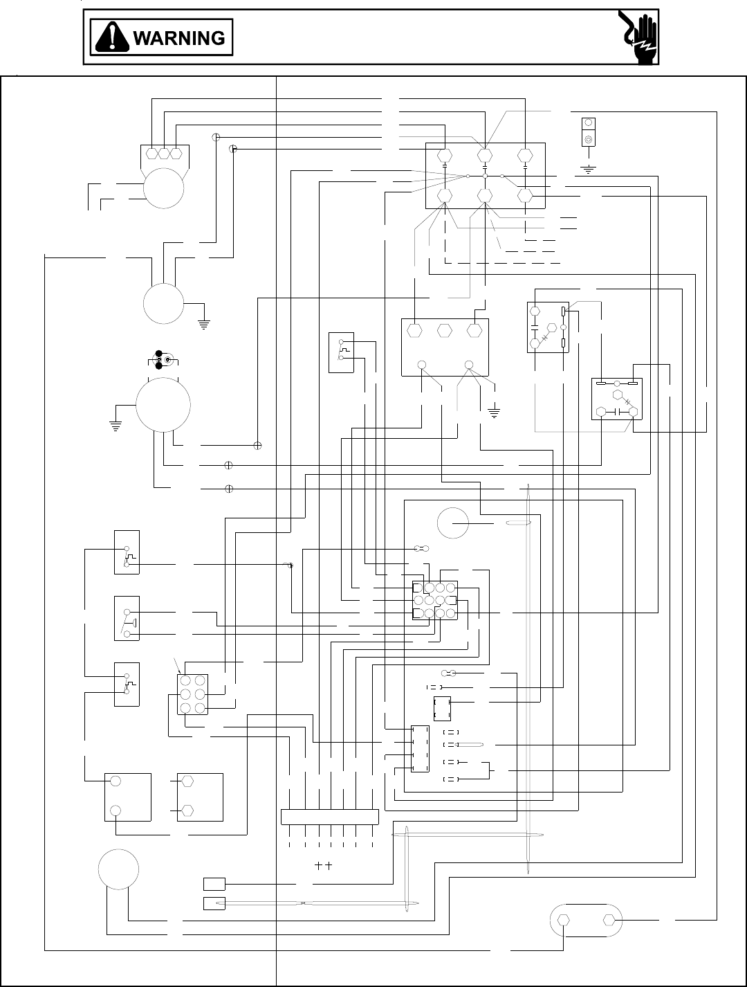
31
GPG13(36)4A WIRING DIAGRAM
Y2
YL
PU
BL
BK
RD
BL
YL
PU YL
BL
PU
PU
NOTE 4
PLF
YL
PU
YL
GR
RD/YL
BK
PU
BK
BR
BR BR
FC
BK
PU
BK
WH
DI
BR
GR
Y1 WYGCR
RD
OR
BL
BL
BL
YL
PU
BL
RD
GR
WH
L2
BL
HEAT COOL
UNUSED
L1
FC
GR
RD
RD
BL BL
WH
YL YL
BL
PU
RD
FS
RD YL
65
4
RD RD
1 3
2
GR
10
79
12
8
11
ECON
YL
RD
OR
BK
RD
RD
RD RD
PU
BL
BL
BL
BK
BK
PU
GR
WH
BL
RD
GR
BL
POWER SUPPLY
YL
BK
YL
BK CH OPTIONAL
460/3/60
SEE NOTE 6
BK
BK
PU
RD
BK
YL RD
GND
RD
BK
BK
RD
CH OPTIONAL
CONNECTED AT L1, L2
NOTE 2
SEE
NOTE 3
SEE
NOTE 5
TO THERMOSTAT
VM
GAS VALVE
IGN
FS
MV
(ALT.) HONEYWELL
GAS VALVE
MV
W. R.
GV
5
41
2
GV
RS
63
PS
ALS
EM
CM
COMP
T3 T2 T1
IIC
C
3
LS TR
24V
480
12
C
L1
VMR
IBR
L3L2
T1 T3T2
31
2
3
1
2
Wiring is subject to change. Always refer to the wiring diagram on the unit for the most up-to-date wiring.
HIGH VOLTAGE!
DISCONNECT ALL POWER BEFORE SERVICING OR INSTALLING THIS
UNIT. MULTIPLE POWER SOURCES MAY BE PRESENT. FAILURE TO
DO SO MAY CAUSE PROPERTY DAMAGE, PERSONAL INJURY OR DEATH.
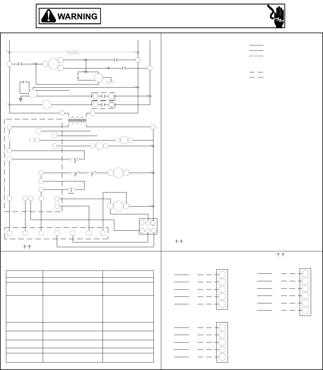
32
GPG13(36)4A WIRING DIAGRAM
NOTE 4
NOTE 5 TR
WITH ECONOMIZER OPTION
BL
PU
RD
GR
WH
GR
RD
YL
BL
NO ECONOMIZER
WH
BL
R
C
Y
G
W
G
R
C
Y
W
GR
RD
YL
PU
2 STAGE COOLING
WH
C
G
R
Y2
Y1
W
NOTE 5
CHECKEQUIP. STATUS
STATUS LIGHT
FAULT
INTERNAL CONTROL
NO POWER OR
NORMAL OPERATION
IGNITION FAILURE
SWITCH
OPEN
SWITCH
OPEN ROLLOUT
OPEN AUX. LIMIT
PRESSURE SWITCH
PRESSURE SWITCH CLOSED
WITHOUT INDUCER ON
COMPRESSOR
OPEN LIMIT SWITCH
OUTPUT DELAY
FALSE FLAME SENSED
5 BLINKS
4 BLINKS
2 BLINKS
6 BLINKS
3 BLINKS
1 BLINK
OR
OR
ON
OFF
CHECK
CHECK
PRESSURE SWITCH
PRESSURE SWITCH
3 MIN. COMP.
BAD SWITCH
STICKING GAS VALVE
MAIN LIMIT OPEN
ANTI-CYCLE TIMER
GAS FLOW
REPLACE CONTROL
CHECK I NPUT POWER
CHECK FUSE ON CONTROL
GAS VALVE
BAD SWITCH
FLAME SENSOR
AUX. LIMIT OPEN
FLAME ROLLOUT
GAS PRESSURE
-
THE STATUS LIGHT ON THE FURNACE CONTROL MAY BE USED AS A GUIDE TO
TROUBLESHOOTING THIS APPLIANCE. STATUS LIGHT CODES ARE AS FOLLOWS:
INSTALLER/SERVICEMAN
TO THERMOSTAT
13
IBR
RWG
910
7
ECON
IIC
3
6
8
F
5
4
HC
Y1 Y2
12
11
CY
C
ALS
PS
D1
FS
LS
RS GV
VMR
FS
L1
FC
EM
C
L1 T1
L1
VM
(HIGH)
(LOW)
FC
VMR
IGN
CM
IBR
CH
460/3/60
SUPPLY VOLTAGE
T2
T3
COMP
T1
T2
T3
NOTE 2
C
C
WH WHITE
YL YELLOW
1. REPLACEMENT WIRE MUST BE THE SAME SIZE AND TYPE OF
INSULATION AS ORIGINAL.(USE COPPER CONDUCTOR ONLY).
0140G00088
4. ACCESSORY ECONOMIZER PLUG (ON SELECT MODELS) ADJACENT
SPEED REPLACE THE BLACK MOTOR LEAD AT IBR#3 WITH RED
3. 460V UNITS ARE SINGLE SPEED, TO CHANGE FROM HIGH TO LOW
THERMOSTAT FIELD WIRING
VENT MOTOR RELAY
VENT MOTOR
ROLLOUT SWITCH
TRANSFORMER
6. USE COOPER CONDUCTORS ONLY.
USE NEC CLASS 2 WIRE.
2. CRANKCASE HEATER NOT SUPPLIED ON ALL UNITS.
5. L1 AND L2 ON IIC CONTROL IS 24V INPUT.
2 SPEED MOTOR
BL - HIGH SPEED
RD/YL - LOW SPEED
TO BLOWER HOUSING IN RETURN AIR COMPARMENT.
LEAD FROM MOTOR.
3
6
PLF 4
21
5
VMR
RS
VM
TR
NOTES
460/3/60
LOW VOLTAGE
LINE VOLTAGE
LOW VOLTAGE
HIGH VOLTAGE
FIELD WIRING
GR GREEN
BR BROWN
BL BLUE
BK BLACK
WIRE CODE
PU PURPLE
OR ORANGE
OPTIONAL HIGH VOLTAGE
FACTORY WIRING
COMPRESSOR
COMPONENT LEGEND
PRESSURE SWITCH
LIMIT SWITCH
FLAME SENSOR
FAN CAPACITOR
EQUIPMENT GROUND
CRANKCASE HEATER
CONDENSER MOTOR
AUXILLARY LIMIT SWITCH
FEMALE PLUG/CONNECTOR
INTEGRATED IGNITION CONTROL
EVAPORATOR MOTOREM
L2
GAS VALVE
IGNITOR
IIC
IGN
GV
PS
PLF
LS
FUSE
F
GND
FS
FC
L2
L3
L2 L3
CONTACTOR
COMP
ALS
CH
C
CM
RD RED
PK PINK
IBR INDOOR BLOWER RELAY
13
1
3
IIC
Wiring is subject to change. Always refer to the wiring diagram on the unit for the most up-to-date wiring.
HIGH VOLTAGE!
DISCONNECT ALL POWER BEFORE SERVICING OR INSTALLING THIS
UNIT. MULTIPLE POWER SOURCES MAY BE PRESENT. FAILURE TO
DO SO MAY CAUSE PROPERTY DAMAGE, PERSONAL INJURY OR DEATH.
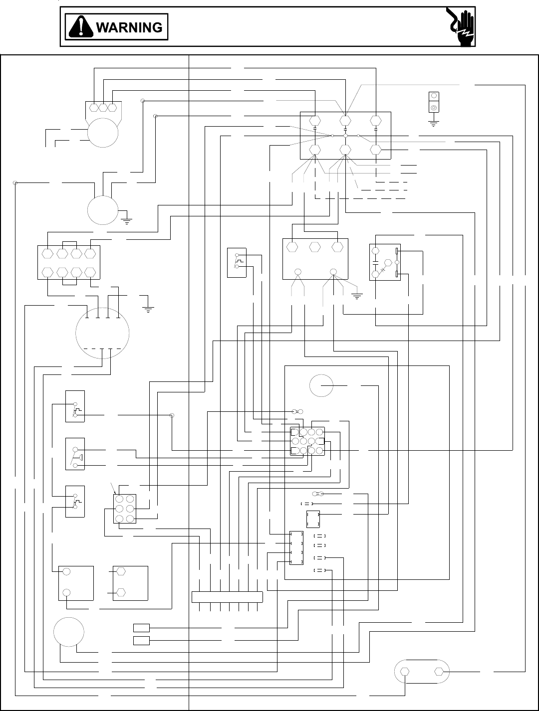
33
Wiring is subject to change. Always refer to the wiring diagram on the unit for the most up-to-date wiring.
GPG13(48,60)4A WIRING DIAGRAM
RD
BL YL
WH
GR
YL
YL WH
YL
RD
GR
YL
BL
RD
RD
BK
PU
BR
PU
BL
BK RD
PU
BK
PU
BK
YL
BL
PU
PU
YL
YL
RD
RD
RD
PU
BR
BL
PU
BL
YL
PU
GR
PU
YL
BL
YL
BK BK
BK
BK
YL
YL
RD RD BL
RD
OR
RD
WH
BL
PU
RD
BK PU
RD
RD
RD
BL
BL
BL
BL
OR
RD
WH
BK
BR
BR
BK
PU
PU
BL
BK
PU YL
BL
BL
BL
YL
WH
BL
WH
YL
YL
GR
RD
YL
YL
WH
WH RD
BK PU
BL
W. R.
GAS VALVE GAS VALVE
(ALT.) HONEYWELL
TO THERMOSTAT
RC G
YW
COOL
P1
ECON
11
8
12
97
10
4
2
56
3
1DI
L1
FS HEAT
UNUSED
L2
GND
POWER SUPPLY
460/3/60
CH OPTIONAL
CONNECTED AT L1, L2
NOTE 2
Y1Y2
CH OPTIONAL
NOTE 4
PLF
T1 T2 T3 T4 T5
NOTE 3
SEE NOTE 5
NOTE 6
SEE
SEE NOTE 7
CM
MV
GV
MV
GV
PS
LS
ALS
L1 L2
C
T1 T2
T1
COMP
T3 T2
VM
RS
C
IIC
FC
FS
IGN
3
2
14
5
6
T3
L3
1
480
24V
2
TR
3
C
VMR
LGN
EM
H4H3H1
TR
H2
X3X4 X2 X1
3
1
2
HIGH VOLTAGE!
DISCONNECT ALL POWER BEFORE SERVICING OR INSTALLING THIS
UNIT. MULTIPLE POWER SOURCES MAY BE PRESENT. FAILURE TO
DO SO MAY CAUSE PROPERTY DAMAGE, PERSONAL INJURY OR DEATH.
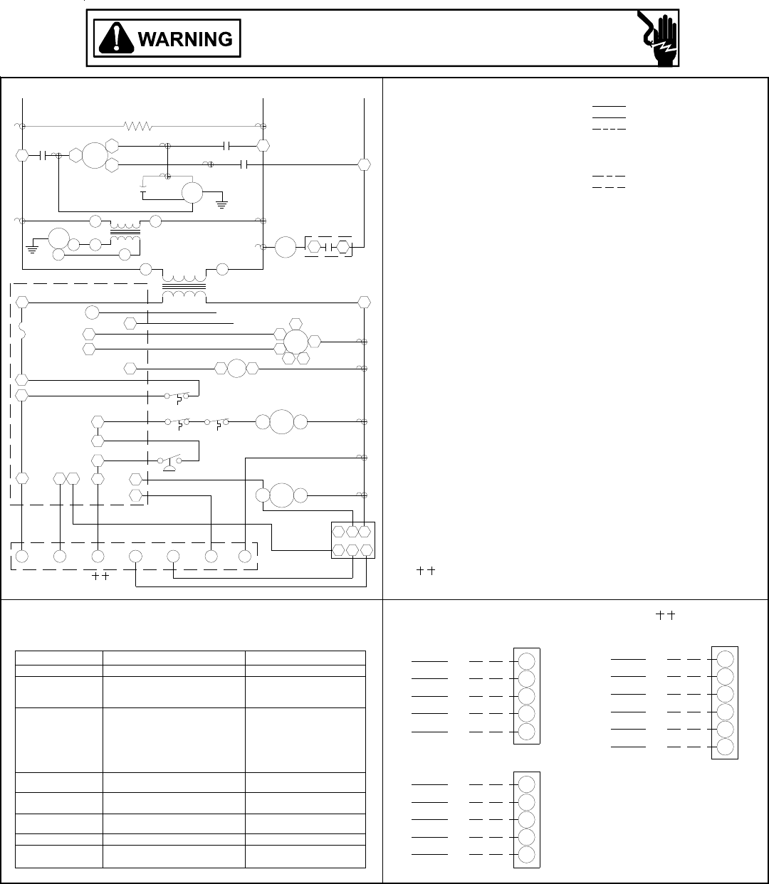
34
GPG13(48,60)4A WIRING DIAGRAM
NOTES
EVAPORATOR MOTOR
EM
RS ROLLOUT SWITCH
TRANSFORMER
TR
FLAME SENSOR
INTEGRATED IGNITION CONTROL
LIMIT SWITCH
FEMALE PLUG/CONNE CT OR
PRESSURE SWITCH
EQUIPMENT GROUND
IIC
IGN
LS
PLF
PS
IGNITOR
GND
FS
GV GAS VALVE
AUXILLARY LIMIT SWITCH
CONDENSER MOTOR
CONTACTOR
CRANKCASE HEATER
COMPONENT LEGEND
CM
C
CH
ALS
PU PURPLE
YL YELLOW
WH WHITE
RD RED
BL BLUE
BR BROWN
GR GREEN
OR ORANGE
PK PINK
WIRE CODE
BK BLACK
LOW VOLTAGE
LOW VOLTAGE
FIELD WIRING
HIGH VOLTAGE
OPTIONAL HIGH VOLTAGE
FACTORY WIRING
LINE VOLTAGE
COMP COMPRESSOR
VM VENT MOTOR
1. REPLACEMENT WIRE MUST BE THE SAME SIZE AND TYPE OF
INSULATION AS ORIGINAL.(USE COPPER CONDUCTOR ONLY).
4. ACCESSORY ECONOMIZER PLUG (ON SELECT MODELS) ADJACENT
TO BLOWER HOUSING IN RETURN AIR COMPARMENT.
2. CRANKCASE HEATER NOT SUPPLIED ON ALL UNITS.
3. FOR DIFFERENT THAN FACTORY SPEED TAP. CHANGE COOLING
SPEED AT MOTOR T4 AND T5 TERMINALS. CHANGE HEATING
SPEED AT MOTOR T1, T2 AND T3 TERMINALS.
HEATING SPEED (WHITE WIRE)
T1 - LOW SPEED
6. L1 AND L2 ON ICC CONTROL IS 24V INPUT.
T2 - MED. SPEED
T3 - HIGH SPEED
T5 - HIGH SPEED
5. USE COOPER CONDUCTORS ONLY.
USE NEC CLASS 2 WIRE.
COOLING SPEED (YELLOW WIRE)
T4 - LOW SPEED
460/3/60
FFUSE
VMR VENT MOTOR RELAY
FC FAN CAPACITOR
7. STEPDOWN TRANSFORMER
460V PRIMARY INPUT & 240V SECONDARY OUTPUT
WITH ECONOMIZER OPTION
WH
GR
RD
PU
BL
BL
YL
RD
GR
WH
NO ECONOMIZER
WH W
W
0140G00089
Y
C
W
R
G
Y
C
R
G
PU Y1
BL
YL Y2
C
GR
RD
G
R
THERMOSTAT FIELD WIRING
2 STAGE COOLING
NOTE 2
TR
NOTE
NOTE 6
NOTE 6
4
SEE NOTE 7
EM
RGWY1
TO THERMOSTAT
11
Y2 Y
C
PLF
65
123
4
4
IIC
ECON
97
8
10 12
6
5
3
FS
F
L1
PS
ALS RS
LS
GV
FS
IGN
VM
L2
SUPPLY VOLTAGE
L1 T1 COMP
T3
CT1 T2
L1
C
FC CM
460/3/60
T2
CH
L2
L2
C
L3
L3
C
T3
D1
C
HCEM
VMR
VMR
13
T4
T3
L
N
31
IIC
T5
T1T2
H1 H4
X4
X1
TR
CHECKEQUIP. STATUS
STATUS LIGHT
FAULT
INTERNAL CONTROL
NO POWER OR
NORMAL OPERATION
IGNITION FAILURE
SWITCH
OPEN
SWITCH
OPEN ROLLOUT
OPEN AUX. LIMIT
PRESSURE SWITCH
PRESSURE SWITCH CLOSED
WITHOUT INDUCER ON
COMPRESSOR
OPEN LIMIT SWITCH
OUTPUT DELAY
FALSE FLAME SENSED
5 BLINKS
4 BLINKS
2 BLINKS
6 BLINKS
3 BLINKS
1 BLINK
OR
OR
ON
OFF
CHECK
CHECK
PRESSURE SWITCH
PRESSURE SWITCH
3 MIN. COMP.
BAD SWITCH
STICKING GAS VALVE
MAIN LIMIT OPEN
ANTI-CYCLE TIMER
GAS FLOW
REPLACE CONTROL
CHECK INPUT POWER
CHECK FUSE ON CONTROL
GAS VALVE
BAD SWITCH
FLAME SENSOR
AUX. LIMIT OPEN
FLAME ROLLOUT
GAS PRESSURE
-
THE STATUS LIGHT ON THE FURNACE CONTROL MAY BE USED AS A GUIDE TO
TROUBLESHOOTING THIS APPLIANCE. STATUS LIGHT CODES ARE AS FOLLOWS:
INSTALLER/SERVICEMAN
Wiring is subject to change. Always refer to the wiring diagram on the unit for the most up-to-date wiring.
HIGH VOLTAGE!
DISCONNECT ALL POWER BEFORE SERVICING OR INSTALLING THIS
UNIT. MULTIPLE POWER SOURCES MAY BE PRESENT. FAILURE TO
DO SO MAY CAUSE PROPERTY DAMAGE, PERSONAL INJURY OR DEATH.
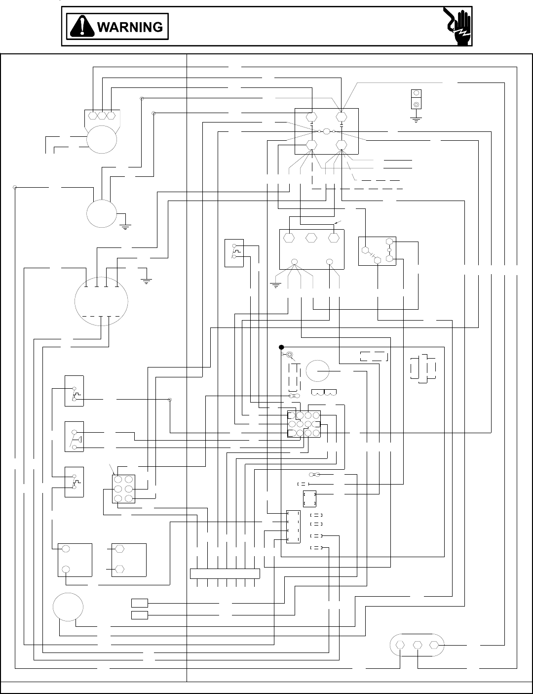
35
GPG13(48,60)1B WIRING DIAGRAM
RD
BL YL
WH
GR
YL
YL WH
YL
RD
GR
YL
BL
RD
RD
BK
PU
BR
PU
BL
BK RD
PU
BK
PUBK
YL
BL
PU
PU
YL
YL
RD
RD
RD
PU
BR
BL
PU
BL
YL
PU
GR
PU
YL
BL
YL
BK BK
BK
BK
YL
YL
BL BL RD
RD
OR
RD
WH
RD
BL
PU
RD
BK PU
RD
RD
RD
BL
BL
BL
BL
OR
RD
WH
BR
BR
BK
PU
PU
BL
RD
PU YL
BL
BL
BL
YL
WH
BL
WH
YL
YL
GR RD
YL
YL
WH
WH RD
FCH
YL
YL
BK
BK
BLRDOR
TO THERMOSTAT
RC GYW
SPEED-UP
BREAK FO R TWO STAGE
T2
C22
MOUNT
T1
P2
REQUIRED
SCREW
COOL
COMPRESSOR
P3
FUSE 3 AMP MAX
F1
P1
135
ECON
120
150
11
8
12
9
7
10
4
2
56
3
1DI
L1
FS HEATUNUSED
L2
GND
POWER SUPPLY
208-230/1/60
CH OPTIONAL
CONNECTED AT L1, L2
NOTE 3
Y1Y2
CH OPTIONAL
NOTE 5
PLF
T1 T2 T3 T4 T5
NOTE 4
NOTE 2
SEE NOTE 6
NOTE 7
SEE
SUPPLY VOLTAGEL1 L2
CM
W. R.
GAS VALVE
MV
GV
GAS VALVE
(ALT.) HONEYWELL
MV
GV
PS
LS
ALS
L1 L2
C
T1 T2
C
COMP
SR
VM
RS
C
IIC
RCCF
FS
IGN
3
2
14
5
6
1
C
24V
2
TR
3
240 3
4
21
VMR
LGN
208
EM
Wiring is subject to change. Always refer to the wiring diagram on the unit for the most up-to-date wiring.
HIGH VOLTAGE!
DISCONNECT ALL POWER BEFORE SERVICING OR INSTALLING THIS
UNIT. MULTIPLE POWER SOURCES MAY BE PRESENT. FAILURE TO
DO SO MAY CAUSE PROPERTY DAMAGE, PERSONAL INJURY OR DEATH.
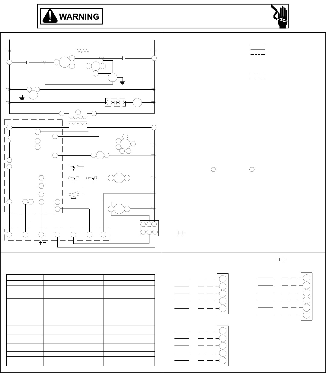
36
NOTES
EVAPORATOR MOTOREM
RS ROLLOUT SWITCH
TRANSFORMERTR
FLAME SENSOR
INTEGRATED IGNITION CONTROL
LIMIT SWITCH
FEMALE PLUG/CONNECTOR
PRESSURE SWITCH
EQUIPMENT GROUND
IIC
IGN
LS
PLF
PS
IGNITOR
GND
FS
GV GAS VALVE
AUXILLARY LIMIT SWITCH
CONDENSER MOTOR
CONTACTOR
CRANKCASE HEATER
COMPONENT LEGEND
CM
C
CH
ALS
PU PURPLE
YL YELLOW
WH WHITE
RD RED
BL BLUE
BR BROWN
GR GREEN
OR ORANGE
PK PINK
WIRE CODE
BK BLACK
LOW VOLTAGE
LOW VOLTAGE
FIELD WIRING
HIGH VOLTAGE
OPTIONAL HIGH VOLTAGE
FACTORY WIRING
LINE VOLTAGE
COMP COMPRESSOR
VM VENT MOTOR
1. REPLACEMENT WIRE MUST BE THE SAME SIZE AND TYPE OF
INSULATION AS ORIGINAL.(USE COPPER CONDUCTOR ONLY).
2. FOR 208 VOLT TRANSFORMER OPERATION MOVE BLACK WIRE
FROM TERMINAL 3 TO TERMINAL 2 ON TRANSFORMER.
5. ACCESSORY ECONOMIZER PLUG (ON SELECT MODELS) ADJACENT
TO BLOWER HOUSING IN RETURN AIR COMPARMENT.
3. CRANKCASE HEATER NOT SUPPLIED ON ALL UNITS.
4. FOR DIFFERENT THAN FACTORY SPEED TAP. CHANGE COOLING
SPEED AT MOTOR T4 AND T5 TERMINALS. CHANGE HEATING
SPEED AT MOTOR T1, T2 AND T3 TERMINALS.
HEATING SPEED (WHITE WIRE)
T1 - LOW SPEED
7. L1 AND L2 ON ICC CONTROL IS 24V INPUT.
T2 - MED. SPEED
T3 - HIGH SPEED
T5 - HIGH SPEED
6. USE COOPER CONDUCTORS ONLY.
USE NEC CLASS 2 WIRE.
COOLING SPEED (YELLOW WIRE)
T4 - LOW SPEED
208-230/1/60
FFUSE
VMR VENT MOTOR RELAY
RCCF RUN CAPACITOR FOR COMPRESSOR/FAN
WITH ECONOMIZER OPTION
WH
GR
RD
PU
BL
BL
YL
RD
GR
WH
NO ECONOMIZER
WH W
W
0140G00267
Y
C
W
R
G
Y
C
R
G
PU Y1
BL
YL Y2
C
GR
RD
G
R
THERMOSTAT FIELD WIRING
2 STAGE COOLING
NOTE 3
TR
NOTE
NOTE 7NOTE 7
5
NOTE 2
EM
RGWY1
TO THERMOSTAT
11
Y2 Y
C
PLF
65
123
4
4
IIC
ECON
97
8
10 12
6
5
3
FS
F
L1
PS
ALS RS
LS
GV
FS
IGN
VM
L2
SUPPLY VOLTAGE
L1 C COMP S
CT1 R
L1
C
CM
208-230/1/60
T2
CH
L2
L2
C
D1
C
HC
13
EM
VMR
VMR
2
T4
T3
LN
321
IIC
T5
T1T2
C
RCCF
F
H
4
CHECK
EQUIP. STATUS
STATUS LIGHT
FAULT
INTERNAL CONTROL
NO POWER OR
NORMAL OPERATION
IGNITION FAILURE
SWITCH
OPEN
SWITCH
OPEN ROLLOUT
OPEN AUX. LIMIT
PRESSURE SWITCH
PRESSURE SWITCH CLOSED
WITHOUT INDUCER ON
COMPRESSOR
OPEN LIMIT SWITCH
OUTPUT DELAY
FALSE FLAME SENSED
5 BLINKS
4 BLINKS
2 BLINKS
6 BLINKS
3 BLINKS
1 BLINK
OR
OR
ON
OFF
CHECK
CHECK
PRESSURE SWITCH
PRESSURE SWITCH
3 MIN. COMP.
BAD SWITCH
STICKING GAS VALVE
MAIN LIMIT OPEN
ANTI-CYCLE TIMER
GAS FLOW
REPLACE CONTROL
CHECK INPUT POWER
CHECK FUSE ON CONTROL
GAS VALVE
BAD SWITCH
FLAME SENSOR
AUX. LIMIT OPEN
FLAME ROLLOUT
GAS PRESSURE
-
THE STATUS LIGHT ON THE FURNACE CONTROL MAY BE USED AS A GUIDE TO
TROUBLESHOOTING THIS APPLIANCE. STATUS L IGHT CODES ARE AS FOLLOWS:
INSTALLER/SERVICEMAN
GPG13(48,60)1B WIRING DIAGRAM
Wiring is subject to change. Always refer to the wiring diagram on the unit for the most up-to-date wiring.
HIGH VOLTAGE!
DISCONNECT ALL POWER BEFORE SERVICING OR INSTALLING THIS
UNIT. MULTIPLE POWER SOURCES MAY BE PRESENT. FAILURE TO
DO SO MAY CAUSE PROPERTY DAMAGE, PERSONAL INJURY OR DEATH.
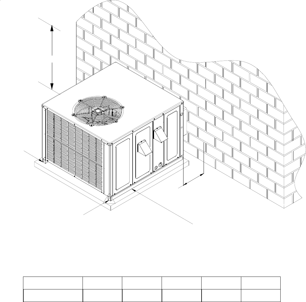
37
RECOMMENDED FILTER SIZES
UNIT 2 Ton 2 1/2 Ton 3 Ton 3 1/2 / 4 Ton 5 Ton
Min. Filter Size (1)20 x 20 x 1 (1)20 x 25 x 1 (1)25 x 25 x1 (2)20 x 20 x 1 (2)20 x 25 x 1
MINIMUM CLEARANCES
-
NOTE: Roof overhang should be no more than 36".
3"
MIN
12" MIN
12" MIN
36" MIN
(FOR SERVICE)
.
48" MIN
38
THIS PAGE LEFT BLANK INTENTIONALLY
39
THIS PAGE LEFT BLANK INTENTIONALLY

40
NOTE: SPECIFICATIONS AND PERFORMANCE DATA LISTED HEREIN ARE SUBJECT TO CHANGE WITHOUT NOTICE
Quality Makes the Difference!
All of our systems are designed and manufactured with the same high quality standards regardless of size or efficiency. We have
designed these units to significantly reduce the most frequent causes of product failure. They are simple to service and forgiving to
operate. We use quality materials and components. Finally, every unit is run tested before it leaves the factory.
That’s why we know. . .There’s No Better Quality.
© 2005 - 2008 Goodman Manufacturing Company, L.P.
Visit our website at www.goodmanmfg.com for information on:
• Products • Parts
• Warranties • Contractor Programs and Training
• Customer Services • Financing Options
