GOSAFE G-G6S-3S GPS Tracker User Manual G6S V1 6
Gosafe Company Limited GPS Tracker G6S V1 6
UserManual.wiki
>
GOSAFE
>
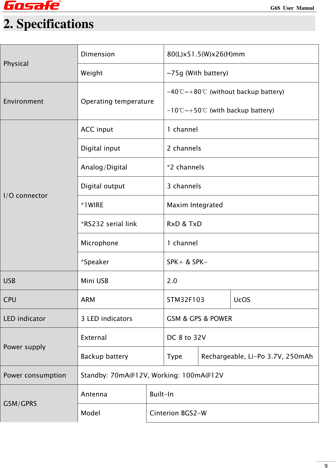
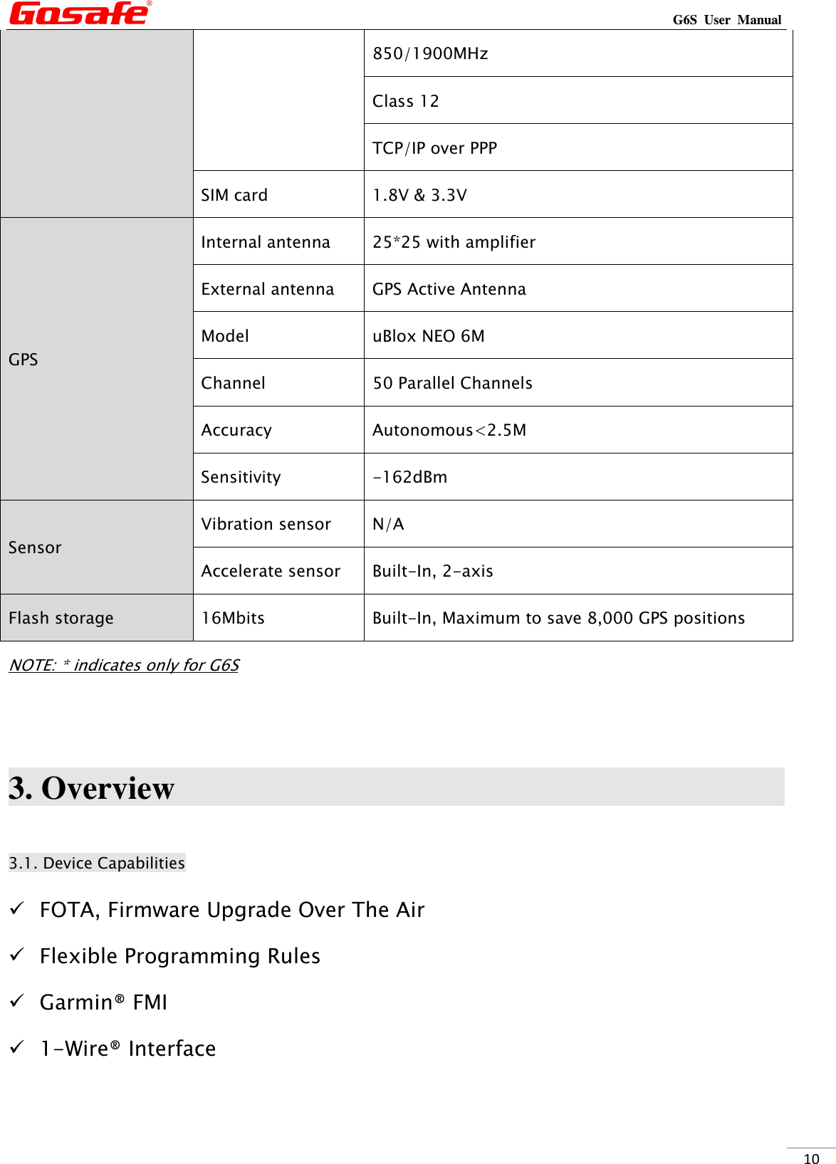
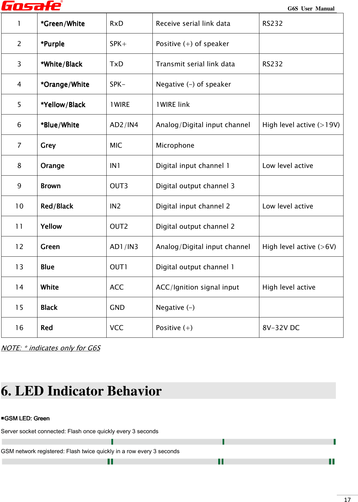
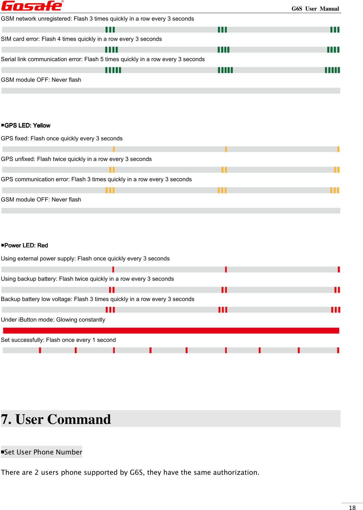
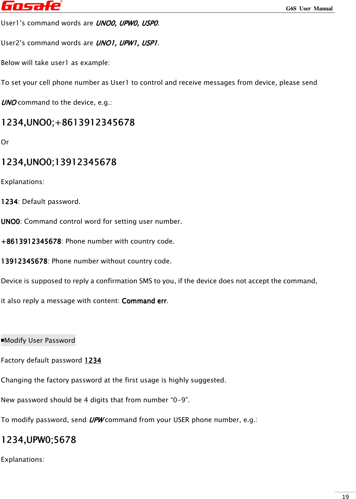
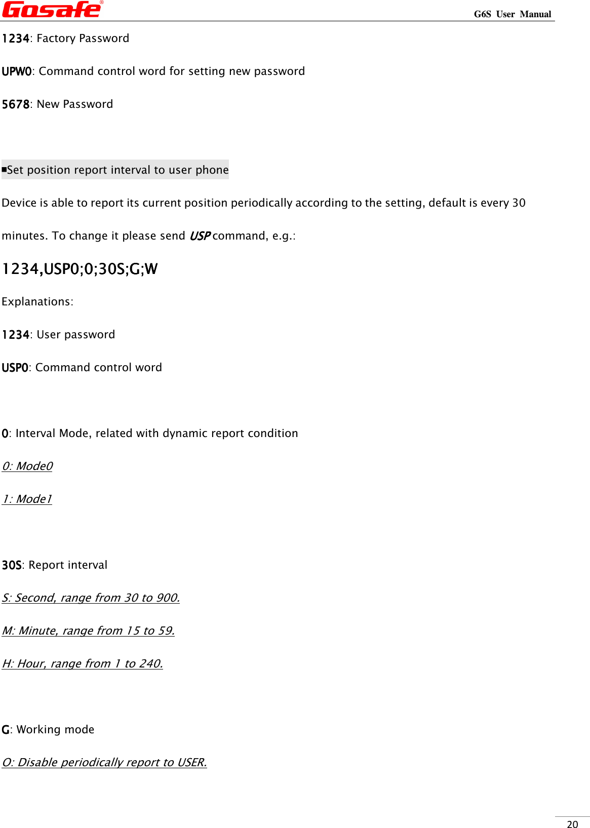
G G6S 3S User Manual
User Manual
Navigation menu
Upload a User Manual
Namespaces
Wiki Guide
HTML
PDF
Info
Views
User Manual
Discussion / Help
Navigation