Gospell Smarthome Electronic GD8122 Full HD Remote Home Surveillance User Manual 8122HE
Shenzhen Gospell Smarthome Electronic Co., Ltd. Full HD Remote Home Surveillance 8122HE
15_GD8122 UserMan r1
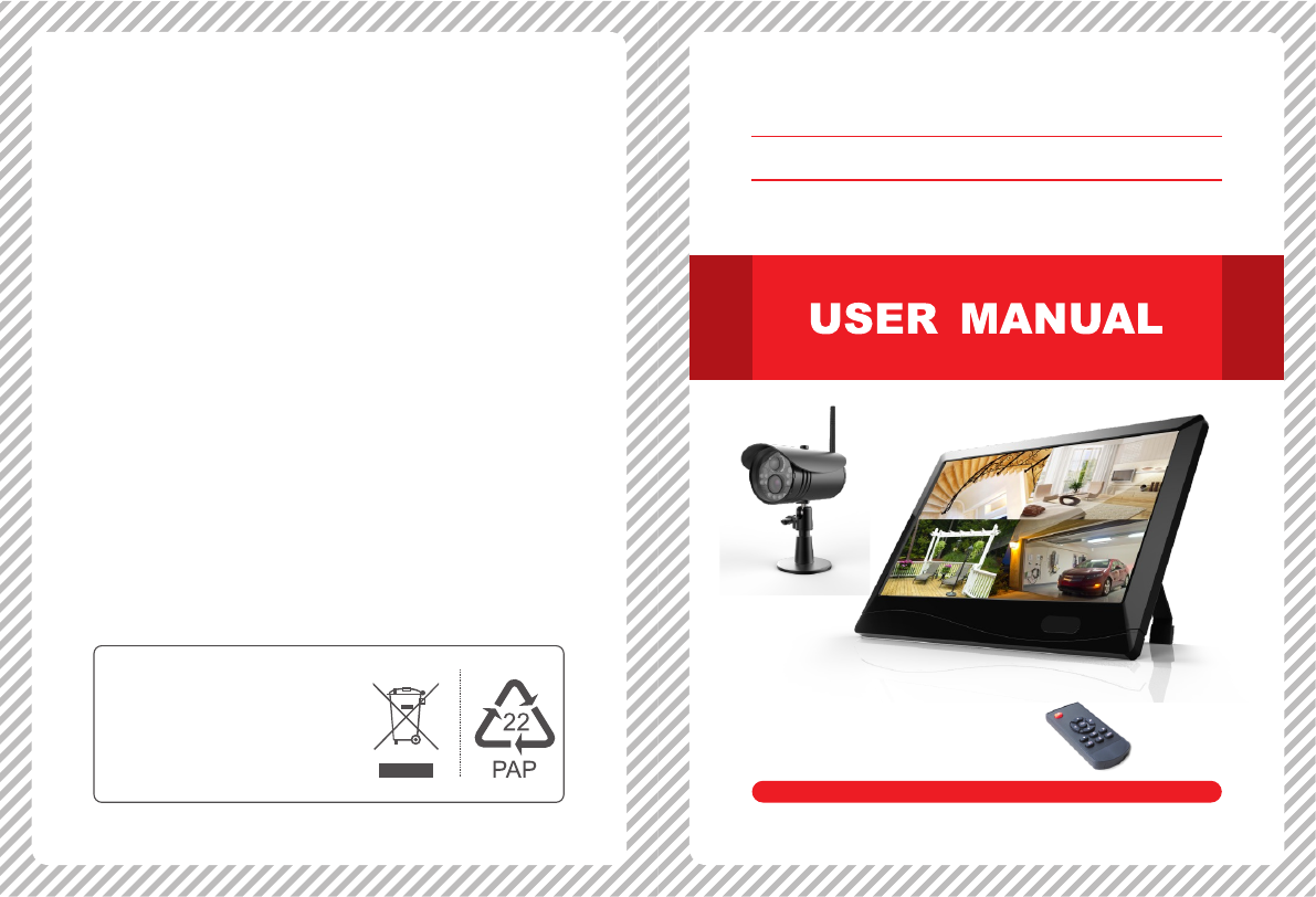
Full HD Remote Home Surveillance
EU Environmental Protection
Please read this user manual carefully before using this product. Failure to
understand operation procedures may result in injury.
Version 1.0
Model: GD8122
Waste electrical products should
not be disposed of with household
waste. Please recycle where
facilities exist. Check with your
local authority or retailer for
recycling advice.
01 02
8122HE=GD8122+GD7122
CONTENTS
1.1 Welcome
1. General information
Thank you for purchasing our products. The product is a high-quality fine-
positioning digital monitoring product designed and developed for the
security and protection field. Please read the instruction of product
carefully before use.
1.2 Precautions
1. The receiver shall not be placed in the position where it's easy to drop or
splashed with liquid;
2. Please turn off the power switch of camera/receiver when don't use the
product for a long time;
3. The power supply can be disconnected completely only when the charger
is unplugged.
4. Do not touch the power switch and receiver with wet hands or goods to
avoid electric shock;
5. If solid or liquid enters the chassis, please disconnect the machine power
and ask qualified technicians to check before restart;
6. When the receiver is shut down, do not unplug the power supply directly.
Instead, please enable the power supply of receiver to be closed
automatically by using the shutdown button on the panel so as to avoid
damage to mobile HDD.
7. If the description of the product or parameters in the instruction is
inconsistent with the material object, please in kind prevail. We reserve
all the right for the final explanation.
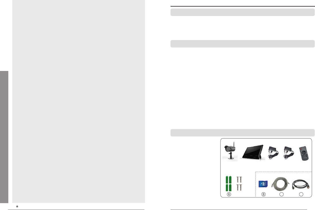
1.3 Packing list
① Camera×(1-4)
② Receiver×1
③ Receiver power×1
④ Camera power×(1-4)
⑤ Remote control×1
⑥ Wall nail×4×(1-4)
⑦ Screw×4×(1-4)
⑧ SD card (optional)×1
⑨ Cable (optional)×1
⑩ HDMI line (optional)×1
※ The pictures in the instruction are for reference only,
please in kind prevail.
(optional)
① ③② ④ ⑤
⑦910
1.
1.1 Welcome ............................................................................................. 02
1.2 Precautions ........................................................................................ 02
1.3 Packing list ........................................................................................ 02
2. D ...................................................................................... 03
3. Installation ........................................................................................... 04
4. Operation
4.1 Basic operation ................................................................................... 05
4.2 Record mode ...................................................................................... 07
4.3 Video playback ................................................................................... 09
4.4 Video deletion .................................................................................... 10
4.5 Video output ..................................................................................... 10
5. Main Menu Setting
5.1 System settings .................................................................................. 10
Network .............................................................................................. 11
Date/time ............................................................................................. 12
Language ............................................................................................ 12
Record mode ...................................................................................... 12
Format SD/USB ................................................................................. 12
.......................................................................... 12
Display items ...................................................................................... 13
System information ............................................................................. 13
System upgrade ................................................................................. 13
Scan mode period .............................................................................. 13
Mute ................................................................................................... 13
....................................................................................... 14
Brightness ........................................................................................... 14
Volume ................................................................................................ 14
Alarm volume ...................................................................................... 14
Power saving mode ........................................................................... 14
About ................................................................................................... 15
5.2 Recording settings ............................................................................. 15
5.3 Video playback ................................................................................... 16
5.4 Camera settings ................................................................................. 16
Pairing ............................................................................................... 16
............................................................................................ 18
PIP settings ......................................................................................... 18
................................................................................ 18
brightness ........................................................................................... 18
5.5 Alarm settings ...................................................................................... 19
6. .................................................. 21
7. ...................................................... 24
8. Specifications ..................................................................................... 28
9. Functional Characteristics ........................................................... 29
10. Fault Diagnosis
10.1 FAQ ................................................................................................. 30
10.2 Fault diagnosis ................................................................................ 31
10.3 Elimination of common diesel engine malfunctions ......................... 32
General information
esignations
Storage for recording
Load default
Activation
Latency vs quality
Operations for iOS Apple Client
Operations for Android Client
03 04
2. esignationsD 3. Installation
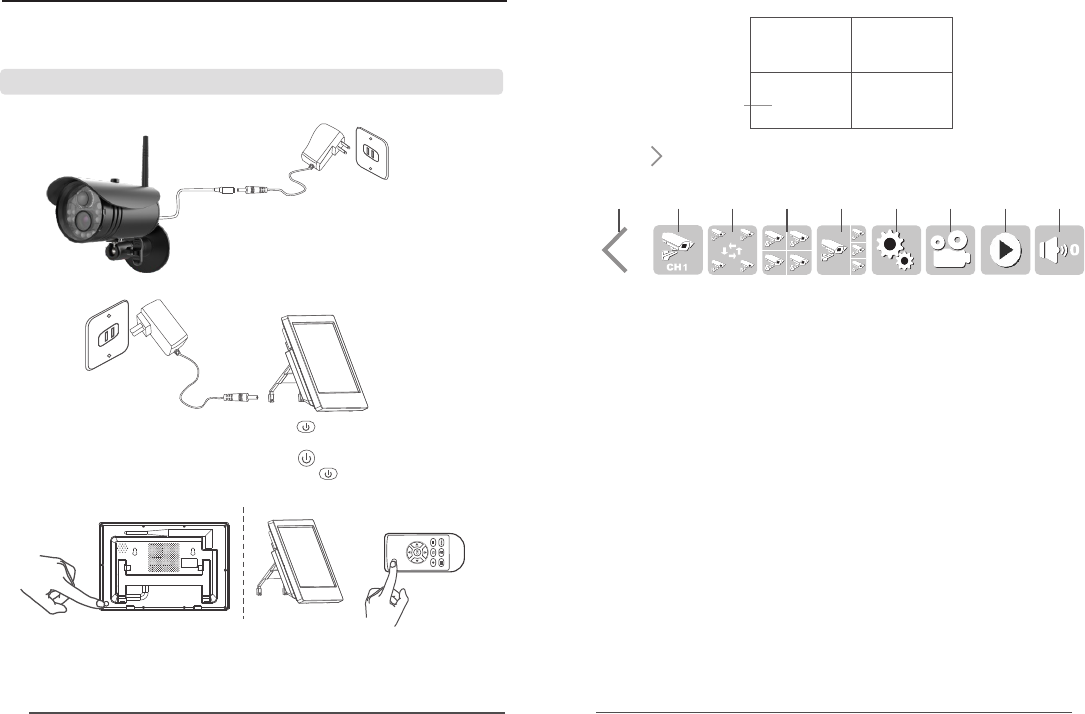
1. Install the camera in a suitable monitoring position and fix it with screws.
2. Install the receiver in a suitable horizontal position (or hang it on the wall).
Nail screw into
the appropriate
place on the wall,
and then hang the
receiver on the
screw
3. Insert the SD card or external storage device such as mobile HDD.
SD card
Mobile HDD
Attention
※ SD card and external storage device do not support hot plug.
※ External storage device or SD card only supports the Fat32 format.
※ If the SD card or external storage device used for this machine is used
before, please format it firstly when using.
※ Please use Class 4 SD card or above, or it cannot be identified.
※ Data in the SD card or mobile HDD cannot be restored after formatting,
please be careful.
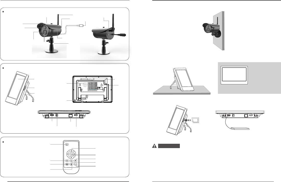
Del/LCD, TV change-over switch
Startup /shutdown
Record
Four-image
Navigation
OK
Playback
Display mode
Menu
Remote control
Receiver
10.1-inch touch screen
SD card slot
Support
Camera GD GD8122
Hanging
Loud speaker
Power switch
USB port
Supply hub
Network port
HDMI interface
Pair key
Supply hub
MIC hole
Camera lens
Infrared lamp
Rain cover Antennas
PIR sensor
Indicator
Support
Photosensitive
induction
hole
(Bottom)
Antennas
05 06
Time stamp
V
Picture display area Picture display area
Picture display area Picture display area
4. Operation
(The following mainly introduces the operating method for remote control,
and operation settings can also be conducted by clicking on the touch
screen.)
4.1 Basic operation
1. Connect the camera with power supply so that the index lamp of camera
will be on.
2. Connect the receiver with power supply.
3. Startup: Under the shutdown state, press on the receiver or remote
control and release it after about 2s to start up the receiver.
Shutdown: Under the startup state, press on the receiver and release
it after 5s to shut down the receiver. Or press on the remote control
and release it after 2s to shut down the receiver.
4. Match the codes of camera and receiver (4 cameras can be connected
simultaneously at most). The codes have been matched already as
factory default. If not, please match the codes according to the "Code
matching" description on Page 16.
5. After successful code matching, the real-time monitoring image will
occur as follows
6. Click at the left bottom of the touch screen with finger to pop up a
setting menu, and click a single icon to enter the setting:
A: A setting menu will be popped up by a single click and packed up when
clicking again;
B: Full image display of a single camera: Sequential click will circulate
from CH1, CH2, CH3 and Ch4;
C: Circulation display: switchover is triggered between circulation
display and disenabled circulation after clicking;
D: Click to enter the four-image display; (Only display when connecting
multiple cameras)
E: Click to enter the one-large three-small image display; (Only display
when connecting multiple cameras)
F: Setting: Click to enter the main menu setting;
G: Video recording: Video recording will start by a single click and stop
when clicking again.
H: Playback: Click to enter the playback interface;
I: Volume: The volume will be circularly set from 0, 1, 2, 3, 4 and 5 by
sequential click, but it defaults to be 3.
A B C D E F G H I
Note: Apply a little force when swiping or clicking the touch screen with finger.
(Since the product adopts resistance screen, gentle force may have no
reaction on the touch screen, but large force may hurt your finger or damage
the screen, so please apply appropriate force.)
2016/01/15/09:30 2016/01/15/09:30
2016/01/15/09:30 2016/01/15/09:30
07 08
8. Press on the remote control to enter the circulation mode display.
The circulation interval time includes 5, 10, 15, 20 and 30s and can be set
under the "System settings".
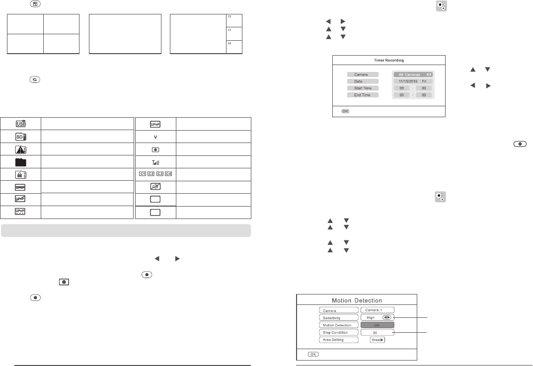
Meanings of icons on the real-time monitoring screen:
4.2 Record mode
Manual recording
1. Under the real-time monitoring state, press and on the remote control
to choose the camera recording videos as the current camera;
2. Press the recording/stop recording key on the remote control. The
recording icon will occur on the display screen to indicate the
recording starts;
3. Press on remote control again to stop recording.
Users can set the starting and ending time of recording on the menu
"Record", the device will make recording automatically according to the
set starting and ending time, and videos will be saved automatically after
recording. Specific steps are as follows:
1. Press MENU on remote control or click on the touch screen to enter
the setting interface;
2. Press or to choose "Record", and then press OK to enter;
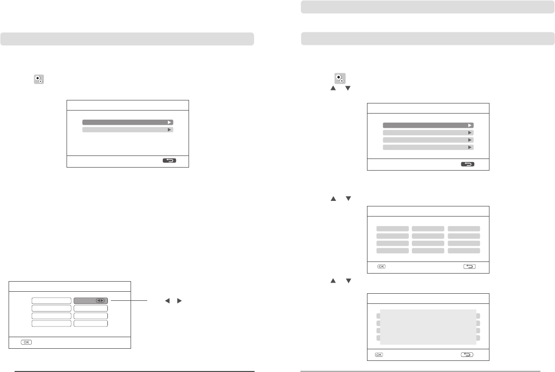
3. Press or to choose “Timer recording" and then press "OK" to enter;
4. Press or to choose "New schedule" and then press "OK" to enter
and set the starting and ending time:
Press or to choose the
items to be set;
Press or to set;
Press OK to confirm the
setting and exit.
5. After setting, the device will record automatically according to the set
starting and ending time.
6. During recording, if pressing the recording/stop recording key on the
device, the recording will stop.
When an object moves in the visual angle range of camera, the device
recording can be triggered. Specific steps are as follows:
1. Press MENU on remote control or click on the touch screen to enter
the setting interface;
2. Press ◄ or ► to choose "Record", and then press OK to enter;
3. Press or to choose "Motion detection " and then press "OK" to enter;
4. Press or to choose the camera to be set;
5. Press ◄ or ► to choose "ON";
6. Press or to choose the items to be changed;
7. Press or to make adjustment;
8. Press OK to confirm the setting and exit.
Motion detection
Timer recording
UPnP is not started or router
firewall is blocked
Network switch failure
Successful network switch
Successful network switch
The camera is the
current camera
Video recording state
Signal intensity
Camera name
Silence
1080P
1080P
720P 720P
Full
Successful mobile HDD
insertion
Successful SD card insertion
Four pictures One picture One large and three small
V
2016/07/15/09:30
V
C2
C3
C4
Picture display area
Picture display area
Picture display area
2016/07/15/09:30
2016/07/15/09:30
2016/07/15/09:30
2016/07/15/09:30
V
2016/07/15/09:30 2016/07/15/09:30
2016/07/15/09:302016/07/15/09:30
Picture display area Picture display area
Picture display areaPicture display area
Picture display area Picture display area
"Sensitivity", "Stop condition" and "Area setting" can also be set in the
motion detection setting:
Prompt appears when SD card
or mobile HD does not access
Prompt appears when SD
card or mobile HD is full
Prompt appears when SD
card or mobile HD is locked
7. Press on the remote control to switch among the 3 display modes:
Sensitivity: "High, medium
and low" are adjustable
The time can be set in second
09 10
07/22/2016 1 / 1
C1 06-11
C2 06-11
DELETE
SD Card 1 / 2
07/22/2016
07/23/2016
DELETE
SD
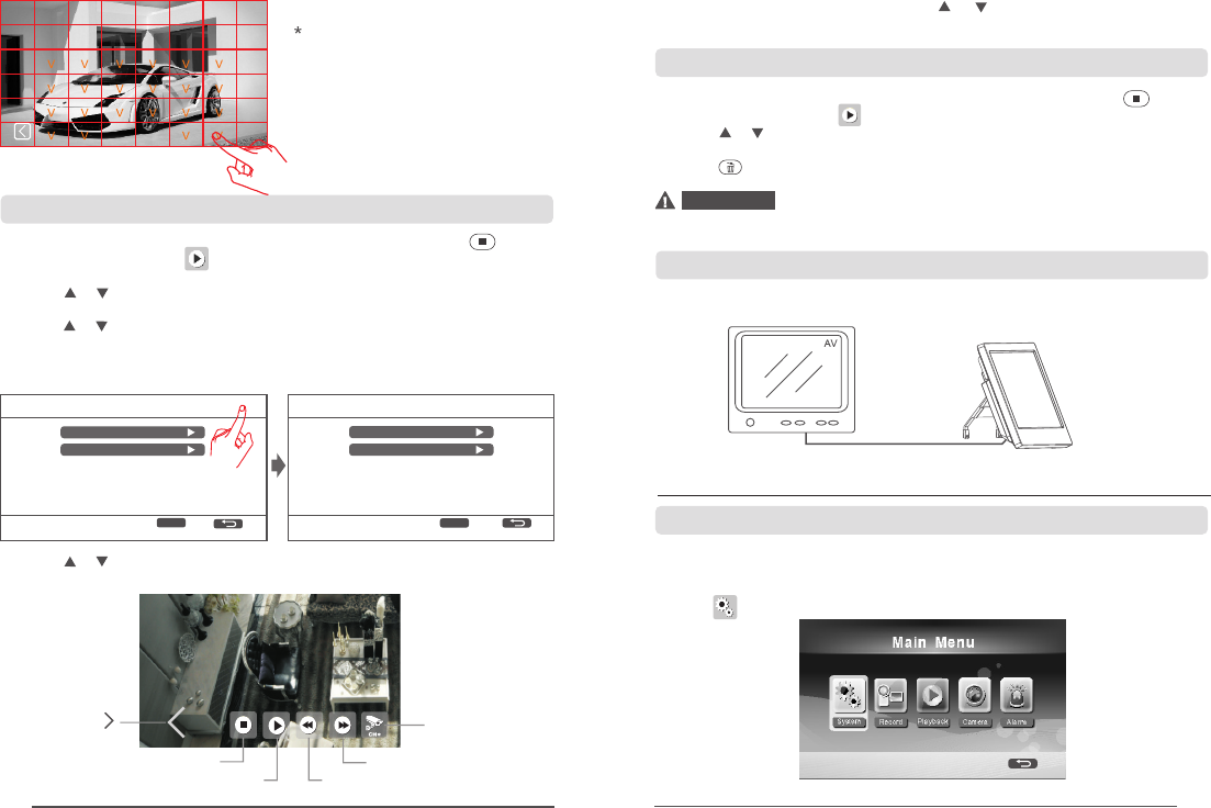
4.3 Video playback
5. Main Menu Setting
1. Under the real-time monitoring state, press the playback key on the
remote control or click on the touch screen to enter the playback
interface:
2. Press or on the remote control to choose the date folder; Press OK to
confirm it and enter;
3. Press or on the remote control to choose camera; Press OK to confirm
it and enter;
4. When SD card and mobile HDD coexist, please click the icon on the top
right corner to switch the storage device.
5. Press or on the remote control to choose the video to be played; Press
OK to play it;
6. Press ◄ or ► for REW or FF; Press or to adjust the volume; Press
OK again to pause the video; Press MENU to exit the play mode.
4.4 Video deletion
1. Under the real-time monitoring state, press the playback key on the
remote control or click on the touch screen to enter the playback folder:
2. Press or on the remote control to choose the video or video folder to
be deleted;
3. Press on the equipment to delete it.
Folders can be deleted only when they are empty.
Attention
4.5 Video output
Connect the receiver to a larger display /TV to see the monitoring video
clearly.
HDMI line
Please click the range to be set:
V : Indicating to choose the
current range
Yellow "V": Indicating to activate
regional motion detection
Area setting
The space unticked represents
closed.
Click this icon on
the screen to
pop up the play
menu Exit
Play/Pause FF
REW
Click to enter the
full-screen display,
click again to enter
the 1-big & 3-small
screen display
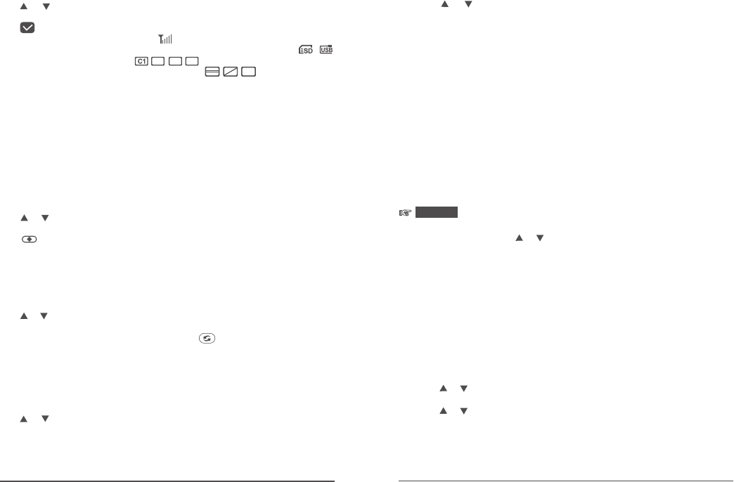
(The following mainly introduces the operating method for remote control,
and operation settings can also be conducted by clicking on the touch screen.)
Under the real-time monitoring state, press "MENU" on the remote control
or click on the touch screen to enter the following interface:
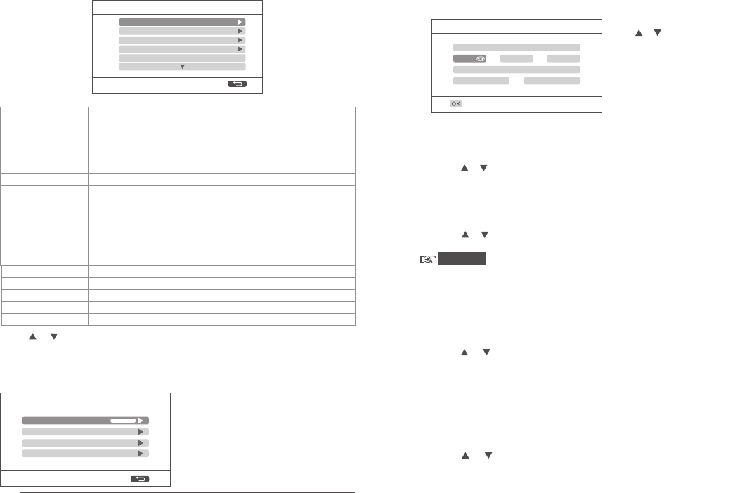
5.1 System settings
11 12
Date / Time
Date
/ /
2016 11 15
Time
:
20 11
Network
Date/time
Language
Set and check the network information;
Set system time and date;
Set system language;
Set whether to stop recording or cover the earlier video
when the storage medium is full;
Record mode
Display items
Format the storage medium or not;
Set the storage medium;
System information
System upgrade
Scan mode period
Mute
Load default
Format SD/USB
Storage for recording
Whether the signal intensity, SD card state, camera names and
the like are displayed on the display screen and video recorded;
Check the system information;
System upgrade:
On or off of loudspeaker on the receiver;
Restore the default settings or not;
Set interval time displayed in cycle on the camera monitoring screen;
Press or to choose an item, and press OK to confirm it.
Network
1. After choosing "Network" on the interface "System ", press OK to enter
and check;
2. Press MENU to exit;
Date/time
After choosing "Time/date" on the interface "System " and press OK to enter
the time/date setting interface;
Press or to select items to
be changed;
Press ◄or ► key to make changes;
Press OK to confirm the changes;
Press the MENU to exit the
time/date setting interface;
Network
Network Password
Network Addressing
Push Notification
Network Information
Press ◄ or ► to select items to
bechanged;
Press OK to confirm the changes;
Modify network parameters;
Press OK to save and confirm;
Press MENU to exit.
Press ◄ or ► on the remote control to choose "System " and press OK to
enter the system setting interface:
System
Network
Record Mode
Language
Date / Time
Format SD/USB
Brightness
Volume
Alarm volume
Power saving mode
Adjust the brightness of LCD screen;
Adjust the volume;
Adjust the alarm volume;
Adjust the power-saving mode;
Language
1. After choosing "Language" on the interface "System ", press OK to enter
the language setting interface;
2. Press or to select the appropriate language, and press OK to confirm
the setting and exit.
About GPL Declaration
Record mode
1. After choosing the "Record mode" on the interface "System", press OK
to enter;
2. Press or to choose "Ordinary" or "Overwriting", and then press OK to
confirm the setting and exit.
Prompt
Ordinary: When SD card or mobile HDD is full, recording will stop automatically;
Overwriting: The system will delete the most previous videos automatically when the SD
card or mobile HDD is fully occupied to clear enough storage space to ensure this
recording.
1. After choosing “ SD/USB " on the interface "System ", press OK to
enter;
2. Press or to choose "Cancel", "SD card" or "USB device";
Cancel: Cancel the formatting;
SD card: Format SD card;
USB device: Format mobile HDD.
3. Press OK for formatting;
4. After the formatting is completed, the hint "Format successful" will prompt.
Format
Format SD/USB
Storage for recording
1. After choosing the "Storage for recording" on the interface "System ",
press OK to enter;
2. Press or to choose "SD card" or "USB device";
3. Press OK to confirm the setting and exit.
13 14
System information
1. After choosing "System information" on the interface "System ", press OK
to enter and check;
2. Press MENU to exit.
System upgrade
1. After choosing the "System upgrade" on the interface "System ", press OK
to enter;
2. Press or to choose the camera to be upgraded;
3. Press OK to make adjustments;
4. Press to make upgrades;
5. Press OK to confirm or press the MENU to exit.
Scan mode period
1. After choosing the "Scan mode period" on the interface "System ", press
OK to enter;
2. Press or to choose time;
3. Press OK again to confirm the setting and exit.
4. Scanning can start only when shot pressing on the remote control
and will stop after pressing again.
Mute
1. After choosing "Mute" on the interface "System ", press OK to enter and
check;
2. Press or to choose "OFF" or "ON";
3. Press OK again to confirm the setting and exit.
Load default
1. After choosing the "Load default" on the interface "System ", press OK to
enter;
2. Press or to choose "Cancel" or "Confirm";
Cancel: Cancel restore defaults;
Confirm: Restore the defaults;
3. Press OK to confirm the setting and exit.
UPnPUPnP UPnP
C2C3 C4
Display items
1. After choosing the "Display items" on the interface "System ", press OK
to enter;
2. Press or key to make selection;
3. Press OK to check whether the item displays. If the item is displayed, the
icon " " behind the item will appear.
RSSI: Icon of signal intensity. Icon:
SD/USB state: Whether SD card or mobile HDD is inserted. Icon:
Camera: Camera name. Icon:
Network: State of network connectivity. Icon:
4. Press the MENU to confirm the setting and exit.
Volume
1. After choosing "Volume" on the interface "System ", press OK to enter
and check;
2. Press ◄ or ► to make adjustments;
3. Press OK to confirm the setting and exit.
Prompt
Under the real-time monitoring state and playback mode, volume can also
be adjusted by pressing or .
Brightness
1. After choosing the "Brightness" on the interface "System ", press OK to
enter;
2. Press ◄ or ► to make adjustments;
3. Press OK to confirm the setting and exit.
Alarm volume
1. After choosing the "Alarm volume" on the interface "System ", press OK
to enter;
2. Press ◄ or ► to make adjustments;
3. Press OK to confirm the setting and exit.
Power saving mode
1. After choosing the "Power saving mode" on the interface "System ",
press OK to enter;
2. Press or key to make selection;
3. Press OK to enter;
4. Press or key to make selection;
5. Press OK to confirm the setting and exit.
15 16
Record
Timer Recording
Motion Detection
5.2 Recording settings
(The following mainly introduces the operating method for remote control,
and operation settings can also be conducted by clicking on the touch screen.)
1. Under the real-time monitoring state, press "MENU" on the remote control
or click on the touch screen to enter the setting interface:
2. Press ◄ or ► to choose "Record";
3. Press OK to enter the following interface:
Timer recording
Set the beginning and ending time of video recording, and the equipment
will make video recordings in accordance with the set time. After recording,
the video will be saved automatically (see Page 8 for specific steps).
Motion detection recording
When an object moves in the visual angle range of camera, the device
recording can be triggered. See Page 8 for specific steps.
5.3 Video playback
See Page 9 for specific steps.
5.4 Camera settings
1. Under the real-time monitoring state, press "MENU" on the remote control
or click on the touch screen to enter the setting interface:
2. Press or to choose "Camera ";
3. Press OK to enter the following interface:
(The following mainly introduces the operating method for remote control,
and operation settings can also be conducted by clicking on the touch screen.)
About
1. After choosing the "About" on the interface "System ", press OK to enter;
2. Press OK to confirm the setting and exit.
Camera
Pairing
Activation
PIP Setting
Latency VS Quality
Pairing
Camera-1Paired 0xe01f0008
Camera-2 Paired 0xe01f0007
Camera-3 Paired 0xe01f0006
Camera-4 Paired 0xe01f0005
The camera will not be interfered by other frequency points after
1. Press or to select "pairing". Press OK key to enter;
pairing
Pairing
Pairing
Camera-1Paired 0xe01f0008
Camera-2 Paired 0xe01f0007
Camera-3 Paired 0xe01f0006
Camera-4 Paired 0xe01f0005
Pairing.....
Long press the PAIR button on TX for 2 seconds
35
2. Press or to choose the camera to be paired;
3. Press OK to enter pairing:
Infrared detection recording
When a human body moves in the visual angle range of camera, the device
recording and intelligent linkage alarm can be triggered. Specific steps are
as follows:
Infrared detection recording
Camera-1 ON
Camera-2
Camera-3
Camera-4
ON
ON
ON
Press of to select "ON or OFF",
press OK key to confirm:
17 18
Activation
Camera-1Off
Paired
Paired
Paired
Camera-2
Camera-4
Camera-3
On
On
On
Pairing OK
Congratulations!!!
5. After successful , the display screen on the receiver will pop up the
following prompts:
pairing
Prompt
Activation
1. Press or to choose "Activation" and then press "OK" to enter;
2. Press or to choose the camera to be set;
3. Press ◄ or ► to choose "ON" or "OFF";
4. Press OK to confirm the setting and exit.
Attention
In the case of "OFF", the camera will not perform any action such as the
display of monitoring screen, video recording and automatic alarm.
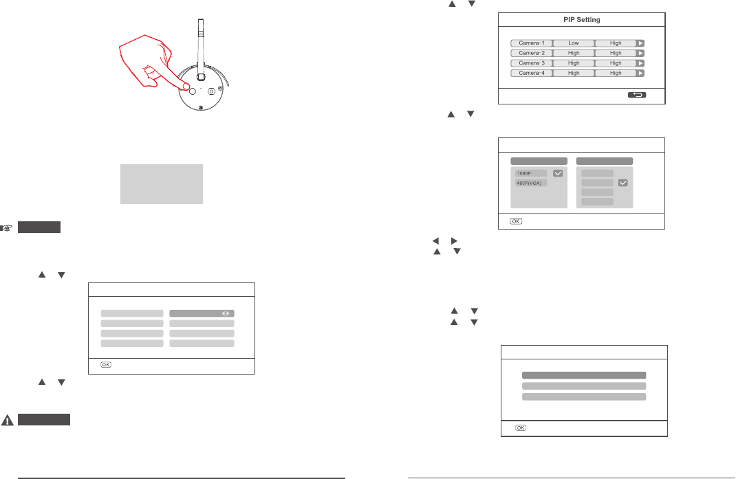
PIP settings
Set the resolution ratio and pixel of video recording.
1. Press or to choose "PIP setting" and press OK to enter;
2. Press or to choose the camera to be set;
3. Press OK to enter the following interface:
If pairing fails, the system prompts “Pairing failed”.
perform pairing again.Please
4. double-color LED red light flickers.
(The camera is on power-on and startup state)
Latency VS Quality
Low Latency, Normal Quality
Medium Latency, Better Quality
High Latency, Best Quality
Latency vs quality
1. Press or to choose "Latency vs quality” and press OK to enter;
2. Press or to choose the image quality to be set;
3. Press OK to confirm the setting and exit.
PIP settings
Resolution size quality
Top High
Medium
Low
High
Press or to choose "resolution ratio" or "image quality";
Press or to choose "Premium", "High", "Medium" or "Low";
Press OK to change;
Press MENU to confirm the setting and exit.
19 20
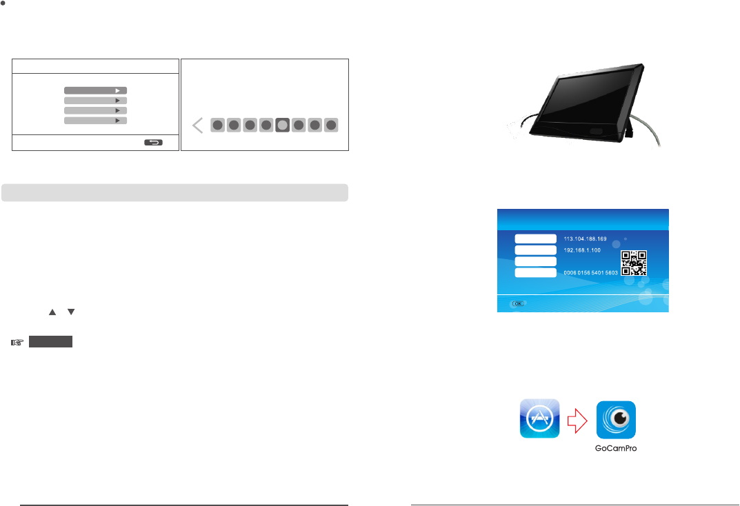
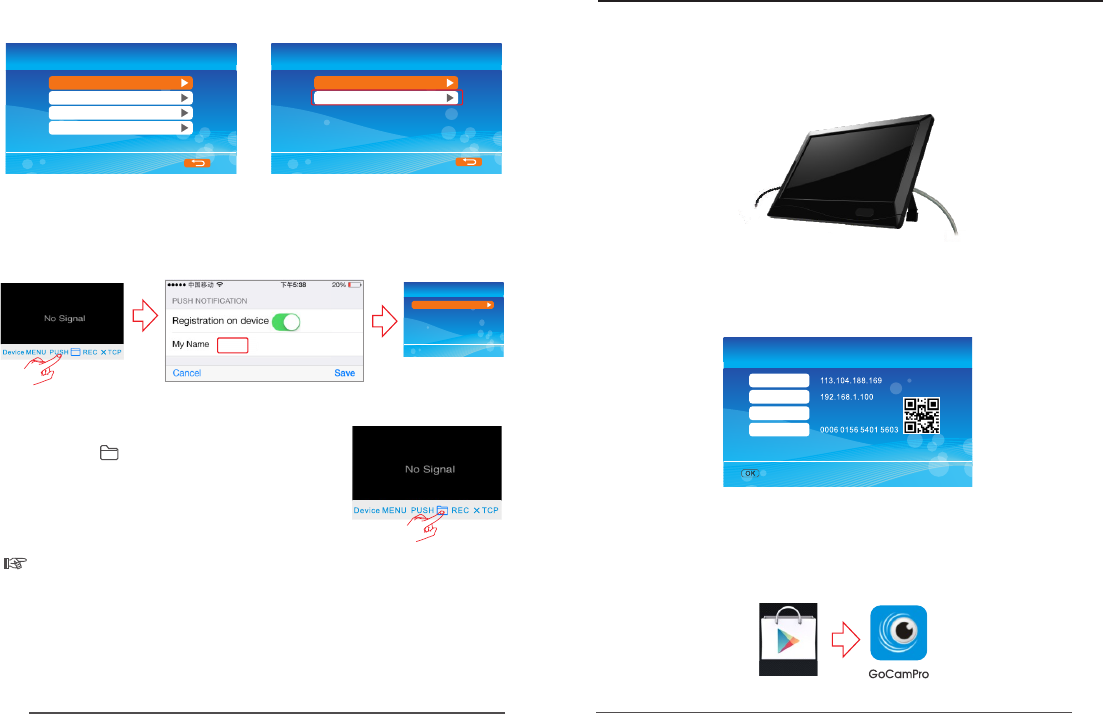
Connect network
Download the client program
1. Turn on the intelligent mobile device terminal and enter “App Store”,then search
and download “ ” software. as the following interface:
GoCamPro
App Store
2. Install the software, as the following interface:
5003
Network ready!
Network
Golbal IP
Local IP
Port
Device ID
1. Connect the cable to the receiver and open the receiver as shown in the
figure below:
Note: The cable connection requires Class 1 router
2. After successful connection, enter "Main menu"=>"System settings"=>
"Network"=>"Network information". The following interface will occur on
the display screen:
Brightness
1 2 345678
Brightness
1. After choosing the "Brightness" on the interface "System ", press OK to enter;
3. Press MENU to confirm the setting and exit.
2. Press ◄ or ► to make adjustments;
Camera-1
Camera-2
Camera-3
Camera-4
3. Press or to choose "Motion detection" or "Infrared detection" and press
▲▼
4. Press or to choose "ON" or "OFF";
5.5 Alarm settings
equipment to enter the setting interface:
enter;
OK to enter;
Prompt Prompt The alarm can make effect only when the infrared
detection or motiondetection recording functions.
The item is to set whether the device will alarm automatically when someone
1. Under the status of real-time monitoring, press the MENU key on the
2. Press ◄ or ► on the remote control to choose "Alarm " and press OK to
5. Press OK to confirm the setting and exit.
moves in the visual angle range of the camera.
21 22
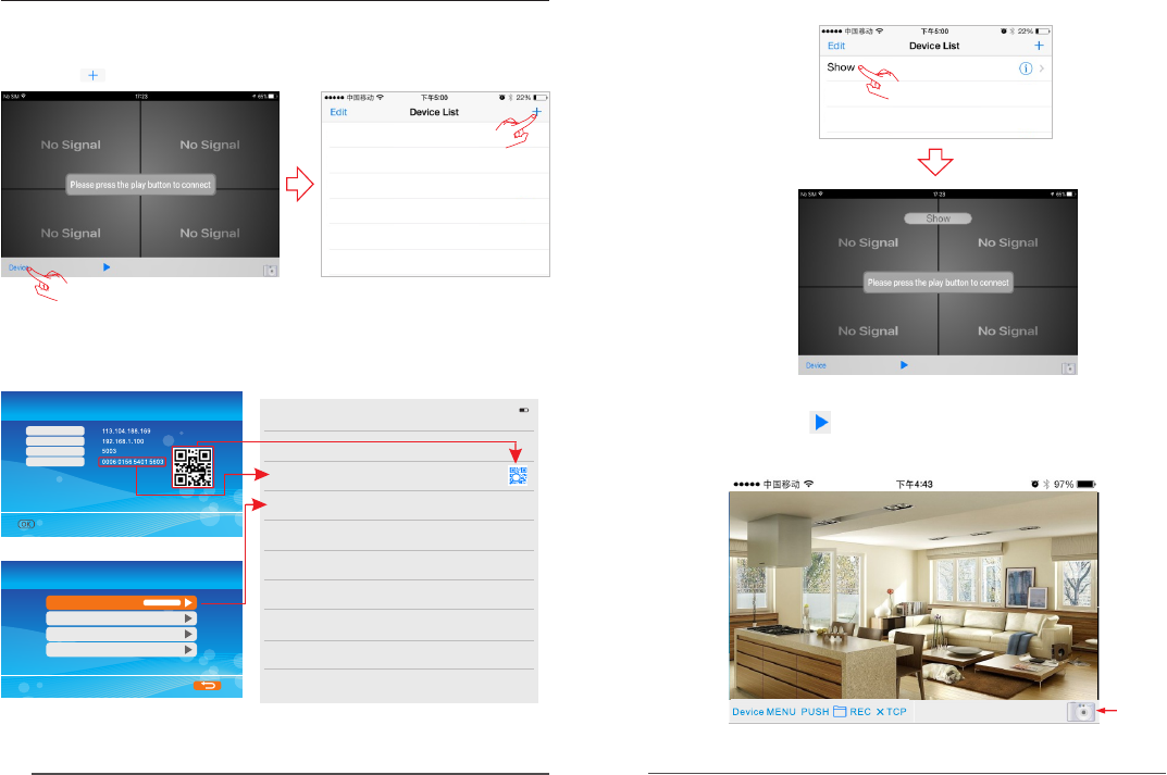
3. To view the video image, you need to choose the right title in the Device list,
then click the line to enter the monitoring mode.
4. Click on the bottom icon. APP will try to connect the RX of the previous
selected title, if connection is successful, the video image will display on the
client.
Take a photo
2013/11/15/16:43
6. Operations for iOS Apple Client
1. Click the APP and enter “Device list” interface.
Click the icon to add new camera.
2.When RX and mobile phone can normally connect to outer net. you just need to set
network password in the receiver, and then input to the mobile phone. Then input the
Device ID in the receiver to the Device ID in the mobile phone or scan the QR code to
get the Device ID.
View image
Network
Network password
Network Addressing
Push Notification
Network information
Devices New Device Save
NAME
Devi ce na me
ID
Devi ce ID
PASSWOR D
Devi ce pa sswor d
ipad 4:4 0 PM 58%
Network information
Global IP
Intranet IP
Port
Device ID
Set the password and enter it to the client
Input to the client
Scan to the client
The network is ready!
23 24
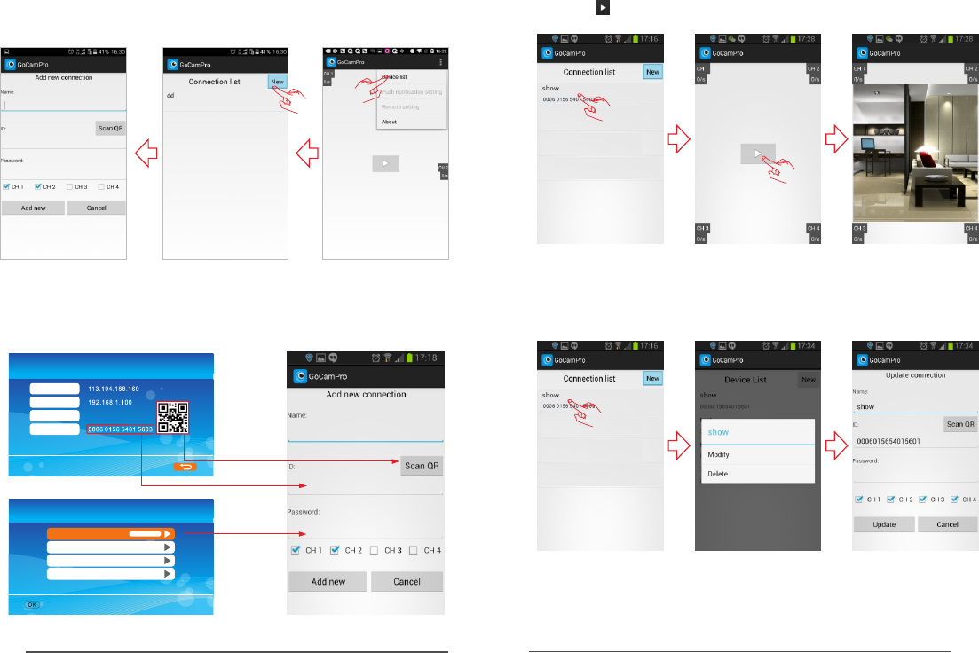
7. Operations for Android Client
1. Turn on the intelligent mobile device terminal and enter “Google play” store,
then search and download “ ” software.GoCamPro
2. Install the software, as the following interface:
Google play
Download the client program
5003
Network ready!
Network Information
Golbal IP
Local IP
Port
Device ID
Connect network
1. Connect the cable to the receiver and open the receiver as shown in the
figure below:
Note: The cable connection requires Class 1 router
2. After successful connection, enter "Main menu"=>"System settings"=>
"Network"=>"Network information". The following interface will occur on
the display screen:
Remarks:
1. Only when the receiver in the real-time state, to view the image.
2. If the Device ID was unable to get to the RX, indicates that RX did not normally
connect outer net, need to check your network.
3. If everything is normal, but still not in the mobile phone client to view images,
please close the client software running always in the background, please try it
again.
4. The network adapter does not support hot-swappable, Before open the RX, The
network is connected with the RX.
Setting Push Notification
1. Turn on the push notification function on the receiver, enter Main Menu System
=> Network => Push Notification, the receiver screen displays the following:
=>
Push Notification
Turn on/off
Minimum Push interval
Time Period
Registered Mobiles
Users can set according to the situation
of Minimum Push interval and time period
Record
Timer recording
Motion Detection
2. Click "PUSH" to Register an account. When there is a movement in front of
camera, it will send a push message to your smart phone. As below shown:
the
After successful registration,
the monitor will receive the
registered account name.
Registered Mobiles
1234
1234
Notice: Only when the motion detection is
open, push notification function will be effective.
When clicking on client-side, you can check
the video data of SD card or mobile hard disk of
the receiver.
Note
automatically stored in the phone.
: The picture took by mobile client-side shall be
Remote viewing video on receiver side
25 26
3. Click the icon, the image will display on the smart phone.
4. Press and hold the device ID to enter the setting interface.
Network
Network Password
Network Addressing
Push Notification
Network Information
5003
Network ready!
Network Information
Golbal IP
Local IP
Port
Device ID
View image
1. Click the Settings and enter device list. add new camera.
Input
Set
password
and input
Or scan
2. When RX and mobile phone can normally connect to outer net. you just need to
input Device ID to the client. or scan the QR code to get the Device ID. the password
is set up in the receiver, and then input to the mobile phone. and saving.
27 28
8. Specifications
All the specifications are subject to minor change without prior notice.
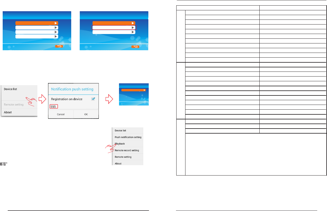
Setting Push Notification
Record
Timer recording
Motion Detection
After successful registration,
the monitor will receive the
registered account name.
Registered Mobiles
555
1. Turn on the push notification function on the receiver, enter Main Menu System
Network tion,
=>
=> => Push Notifica the receiver screen displays the following:
Users can set according to the situation
of Minimum Push interval and time period
2. Click "Notification push setting" to register an account. When there is a movement
in front of camera, it will send a push message to your smart phone. As below
shown:
the
1. Only when the receiver in the real-time state, to view the image.
2. If the Device ID was unable to get to the RX, indicates that RX did not normally
connect outer net, need to check your network.
3. If everything is normal, but still not in the mobile phone client to view images,
please close the client software running always in the background, please try it
again.
Push Notification
Turn on/off
Minimum Push interval
Time Period
Registered Mobiles
4. The network adapter does not support hot-swappable, Before open the RX,
The network is connected with the RX.
Notice: Only when the motion detection or PIR
Recording is open, push notification function
will be effective.
When clicking on client-side, you can check
the video data of SD card or mobile hard disk of the
receiver.
Playback
Note:
automatically stored in the phone.
The picture took by mobile client-side shall be
Remote viewing video on receiver side
Remarks:
Push notification setting
1/2.7",CMOS
DC 12V/2A
At most support 128GB
255 x37x173 (mm)
-10 ~50℃ ℃
USB 2 0 .
At most support 3TB.
1024(R.G.B.) X 600
30fps (one path) / 15fps (four paths)
DC 12V/1A
IP66
≤3Lux
Items
Image sensor
Effective pixel
Horizontal view angle
Power Supply
Waterproof Capacity
Night Vision Distance
Dimensions(W*D*H)
Weight
Dimension of the Display Storage Format
Screen resolution
SD card capacity
Hard disk capacity
Video frame rate
Data output
Frequency range
Dimensions(W*D*H)
Weight
Operating Temperature
10.1 TFT LCD
"
15~85%RH
0 ~40℃ ℃
Operating Temperature
Operating Humidity
Outdoor 300 meters (Maximun)
Wireless transmission distance
8122HE
69x59x130mm
1080P
832g
238g
85 5± °
The lowest illuminance
10M
Storage Format AVI
Power supply
Operating Humidity 15~85%
2 4GHZ.
Modulation method 16QAM
Camera Resolution
Monitor
Frequency response characteristic
PIR Recording

29 30
1. Why the screen doesn’t display any monitoring picture after the camera is
connected?
Answer: 1. Please check whether “Active” is set to “ON”.
2. Please check whether pairing succeeds.
2. The recording time is set already or the motion detection recording is enabled,
but the receiver does not start recording when the time comes or a motion is
detected. Why?
Answer: 1. Check whether the storage medium is inserted.
2. Check whether the storage medium is full.
3. The system does not respond when the playback button is pressed. Why?
Answer: Please check whether the current camera is in the recording status.
If it is in the recording status, the system will not respond when this button is
pressed.
When human body moves beyond the angle of lens and within the angle of
senor, an alarm can also occur on the device. However, the display device cannot
display human body's move in the picture area.
4. Why cannot see human body in the picture area, when the alarm occurs?
Answer: of lens. For the product, the angle of sensor is greater than that
10.1 FAQ
10. Fault Diagnosis
9. Functional Characteristics
Support simultaneous access, recording and browsing of 4 paths wireless
*
HD cameras;
Free of wiring and easy to install;
*
Safe digital wireless, free of interference and able to avoid privacy disclosure;
*
10.1-inch touch display screen and integrated camera;
*
Support 128GB SD card and can externally connect mobile HDD of up to 3TB;
*
Various recording modes available; Manual recording, timing recording and
*
motion detection recording;
Up to 20m of night visual range;
*
Outdoor rainproof camera with a barrier-free transmission distance of 300m;
*
With video transmission function, and external larger display screen
*
accessible;
With IR-CUT function.
*
Remote viewing of real-time monitoring available through iPhone/Android
*
device;
Please note the monitor is not a computer, so some memory devices
cannot operate on it.
31 32
10.3 Elimination of common diesel engine malfunctions
1.Start up UPnP potion of router
If there appears “network is normal (UPnP is not started up)” in main
menu>>system setting>>network>>network information, it is strongly
recommended to start the UPnP potion of the router to which the receiver
is connected. Whether UPnP potion of the router to which the receiver
is connected is started up? If yes, the receiver will have a better
performance, and if not, it just has an ordinary performance.
2.Connect receiver to the outmost router:
If there appears “Too deep RX path” in main menu>>system setting>>
network>>network information, that means too many routers are connected
in series and the router to which the receiver is connected is not the
outmost one. Please connect the receiver to the outmost router.
3.Router firewall
If there appears “UPnP is started up, but not available” in main menu>>
system setting>>Network>>network information, it is recommended to
close the router firewall.
4.The icon on monitoring screen of the receiver (RX) refers to that the
network is not ready yet.
The receiver is in the monitoring screen and the network option is displayed
as open. The possible reasons are as follows if above icon still appears
after 30 seconds of starting up:
A.Network setup is not finished.
B.Abnormal network card.
C.Abnormal network cable.
D.Abnormal router
E.Abnormal ADSL cable
Please eliminate above abnormal reasons.
5.The icon on monitoring screen of the receiver (RX):
UPnP option The receiver is in the monitoring screen and the network option
is displayed as open. The possible reasons for above icon are:
A.UPnP of the router to which the receiver is connected is not started up;
please start it. See the instruction manual of router for the detailed situation
and setting methods.
B.UPnP of the router to which the receiver is connected has been started up,
but its function is stopped by the fire wall. It is recommended to close the
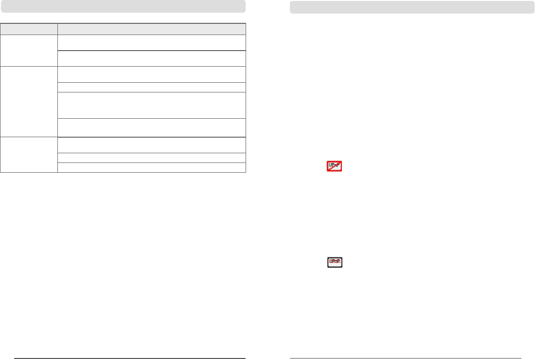
Problems Solutions
There is no video
Poor
picture quality
Check whether "Active" is set to "ON".
Re-pair.
Whether the storage medium is inserted.
Whether the storage medium is full.
If the SD card connection fails, it is suggested to use SD card with
brand like Kingston, SanDisk, Panasonic, Kingmax, etc.
Failure in Mobile Hard Disk connection. It is suggested to use Mobile
Hard Disk with brand like IBM, Toshiba or Seagate, etc.
Whether there is interference, such as WiFi or other wireless devicees.
Whether the antennas of the receiver and camera are installed.
Whether infrared night-vision light is on, which leads to the color cast?
10.2 Fault Diagnosis
the LED does not
display monitoring
picture
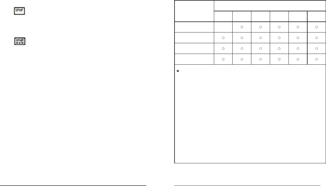
The name and content of hazardous substances in the product
To meet the related regulations and requirements of Chinese Controlling and Administrative
Measures for Pollution of Electronic Information Products (The 39th Order Issued by Ministry
of Industry and Information Technology of the People's Republic of China), the toxic and
harmful substances in the products manufactured and marketed by the company are classified
by the components, proclaimed as follows:
Name and Content of the Toxic and Harmful Substances or Elements in the Products
33 34
router firewall. See the instruction manual of router for the detailed situation
and setting methods.
C.The receiver cannot use the function of UPnP and the client can connect
to the receiver (RX), but in bad performance and small client fps.
D.There are many routers whose UPnP has been started up and fire wall
has been closed, but the receiver still cannot use the function of UPnP, i.e.
the situation that “network is normal (UPnP is not started up)” or “UPnP is
started up, but not available” may appear.
6.The icon on monitoring screen of the receiver refers to the optimal
network status.
The receiver is in the monitoring screen and the network option is displayed
as open. If the above icon appears when no client is connected to, your
network has reached the optimal status.
7.The icon on monitoring screen of the receiver refers to numbers of
client connected
The receiver is in the monitoring screen and the network option is displayed
as open. If one more client is connected, one more dot will be appeared at
the bottom of the icon. The above icon indicates three clients are connected
to the receiver.
8.Wrong information of the client (cell phone or pad):
A.“Unable to resolve host 'ns.davdns.com'”, “Cannot access Internet”:
the client cannot connect to the Internet. Please check whether Wi-Fi or
3G/4G of the client has been opened and ensure the client can normally
surf the Internet.
B. “Cannot connect to server (ns.davdns.com) (1)”: the client cannot
connect to the server. Please check whether the server can normally work.
C.“Device is offline at ns.davdns.com (0006015610431129)”:
the possible situations are: the receiver is not started up; the receiver is
not connected to network; the receiver is not registered in the server;
the receiver software and client APP do not use the same server. Please
check whether the receiver can normally work; whether the network is
ready; whether the software is applied in a correct approach.
D.Connection timeout: the receiver has been registered in the server, but
the client (cell phone or pad) cannot connect to the receiver. The possible
problems are: insufficient network bandwidth, network jam, or network
is blocked by the firewall or NAT.
Component name
Toxic and harmful substances or elements
Machine
Power components
Cables and cable sets
Accessories
Pb Hg Cd Cr (VI)PBB PBDE
×
material lof this component is under limit requirement of the SJ/T11363-2006
X: Indicates that content of this toxic and harmful substance in all homogeneous
material of this component is under limit requirement of SJ/T11363-2006 standard.
All components labeled with "X" indicate they comply with the RoHS regulations of
the European Union.
Machine: It includes printed circuit board and the components, electronic
In accordance with the different product model, the purchased product may not
contain all the above components.
Electronic & information products sold within the People's Republic of China must
have this mark labeled; the figure in it refers to its service life under normal
Indicates that content of this toxic and harmful substance in all homogeneous
standard.
components, etc.
conditions.
Federal Communication Commission (FCC) Radiation Exposure Statement
When using the product, maintain a distance of 20cm from the body to ensure compliance with
RF exposure requirements.
FCC statements:
This device complies with part 15 of the FCC rules. Operation is subject to the
following two conditions: (1) this device may not cause harmful interference, and (2)
this device must accept any interference received, including interference that may
cause undesired operation.
NOTE: The manufacturer is not responsible for any radio or TV interference caused
by unauthorized modifications or changes to this equipment. Such modifications or
changes could void the user’s authority to operate the equipment.
NOTE: This equipment has been tested and found to comply with the limits for a
Class B digital device, pursuant to part 15 of the FCC Rules. These limits are designed
to provide reasonable protection against harmful interference in a residential
installation. This equipment generates uses and can radiate radio frequency energy
and, if not installed and used in accordance with the instructions, may cause harmful
interference to radio communications. However, there is no guarantee that
interference will not occur in a particular installation. If this equipment does cause
harmful interference to radio or television reception, which can be determined by
turning the equipment off and on, the user is encouraged to try to correct the
interference by one or more of the following measures:
‐ Reorient or relocate the receiving antenna.
‐ Increase the separation between the equipment and receiver.
‐Connect the equipment into an outlet on a circuit different from that to which the
receiver is connected.
‐Consult the dealer or an experienced radio/TV technician for help.