Graco Inc Gc 1412 Users Manual 1412D Internal Chop System Operation
GC-1412 to the manual e6da7277-a33a-47ce-a1ff-af2f0f82f3be
2015-02-09
: Graco-Inc Graco-Inc-Gc-1412-Users-Manual-561580 graco-inc-gc-1412-users-manual-561580 graco-inc pdf
Open the PDF directly: View PDF ![]() .
.
Page Count: 32
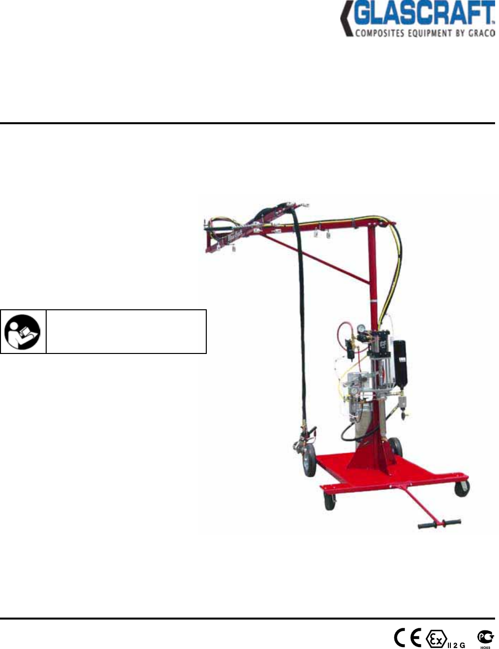
Operation
Internal Chop System GC-1412D
Important Safety Instructions
Read all warnings and instructions in
this manual. Save these instructions.
Low Emission Internal-Mix Gel-Coat
For use with Polyester Resin, and Gel-Coat
Maximum fluid working pressure by
Fluid Section Assembly:
20864-05 - 1300 psi. (9 MPa, 90 bar)
21780-01 - 1700 psi. (12 MPa, 117 bar)
22026-01 - 2000 psi. (14 MPa, 138 bar)
Maximum air pressure:
100 psi. (0.7 MPa, 7 bar)
2 GC-1412D
Contents
Warnings
Warnings ............................................................................................................................................................ 3
Important Safety Information ............................................................................................................................. 5
Grounding .......................................................................................................................................................... 6
Set-up
Set-up Instructions ............................................................................................................................................. 7
Pressure Relief Instructions ............................................................................................................................... 19
Start-up Instructions ........................................................................................................................................... 20
Shut-down Instructions ....................................................................................................................................... 22
Parts ................................................................................................................................................................... 23
Assembly Drawings ............................................................................................................................................ N/A
Sub-Assembly Drawings .................................................................................................................................... 24
Maintenance
Maintenance ....................................................................................................................................................... 29
Technical Data
Technical Data .................................................................................................................................................. 30
Notes ................................................................................................................................................................. 31
Graco Ohio Standard Warranty ....................................................................................................................... 32
Graco Ohio Information ................................................................................................................................. 32
N/A = Non Applicable
GC-1412D 3
9CTPKPIU
The following warnings are for the setup, use, grounding, maintenance, and repair of this equipment.
The exclamation point symbol alerts you to a general warning and the hazard symbol refers to procedure-
VSHFL¿FULVN5HIHUEDFNWRWKHVHZDUQLQJV$GGLWLRQDOSURGXFWVSHFL¿FZDUQLQJVPD\EHIRXQGWKURXJKRXWWKH
body of this manual where applicable.
• See Important Safety Information - MEKP, Polyester Resins and Gel-Coats and Spraying and Lamination
Operations section of this manual.
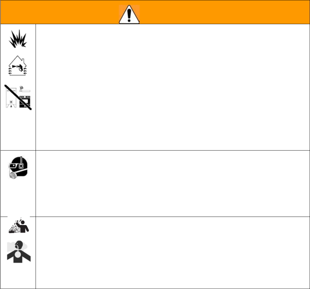
9#40+0)
FIRE AND EXPLOSION HAZARD
Flammable fumes, such as solvent and paint fumes, in work area can ignite or explode. To help
SUHYHQW¿UHDQGH[SORVLRQ
• Use equipment only in well ventilated area.
• Eliminate all ignition sources; such as pilot lights, cigarettes, portable electric lamps, and plastic
drop cloths (potential static arc).
.HHSZRUNDUHDIUHHRIGHEULVLQFOXGLQJVROYHQWUDJVDQGJDVROLQH
'RQRWSOXJRUXQSOXJSRZHUFRUGVRUWXUQSRZHURUOLJKWVZLWFKHVRQRURIIZKHQÀDPPDEOH
fumes are present.
*URXQGDOOHTXLSPHQWLQWKHZRUNDUHD6HHGrounding instructions.
• Use only grounded hoses.
+ROGJXQ¿UPO\WRVLGHRIJURXQGHGSDLOZKHQWULJJHULQJLQWRSDLO
,IWKHUHLVVWDWLFVSDUNLQJRU\RXIHHODVKRFNstop operation immediately. Do not use
equipment until you identify and correct the problem.
.HHSDZRUNLQJ¿UHH[WLQJXLVKHULQWKHZRUNDUHD
• See additional information on MEKP in the MEKP Section of this manual.
PERSONAL PROTECTIVE EQUIPMENT
You must wear appropriate protective equipment when operating, servicing, or when in the
operating area of the equipment to help protect you from serious injury, including eye injury,
LQKDODWLRQRIWR[LFIXPHVEXUQVDQGKHDULQJORVV7KLVHTXLSPHQWLQFOXGHVEXWLVQRWOLPLWHGWR
• Protective eyewear
&ORWKLQJDQGUHVSLUDWRUDVUHFRPPHQGHGE\WKHÀXLGDQGVROYHQWPDQXIDFWXUHU
• Gloves
• Hearing protection
TOXIC FLUID OR FUMES HAZARD
7R[LFÀXLGVRUIXPHVFDQFDXVHVHULRXVLQMXU\RUGHDWKLIVSODVKHGLQWKHH\HVRURQVNLQLQKDOHGRU
swallowed.
5HDG06'6¶VWRNQRZWKHVSHFL¿FKD]DUGVRIWKHÀXLGV\RXDUHXVLQJ
6WRUHKD]DUGRXVÀXLGLQDSSURYHGFRQWDLQHUVDQGGLVSRVHRILWDFFRUGLQJWRDSSOLFDEOH
guidelines.
• Always wear impervious gloves when spraying or cleaning equipment.
4 GC-1412D
9#40+0)
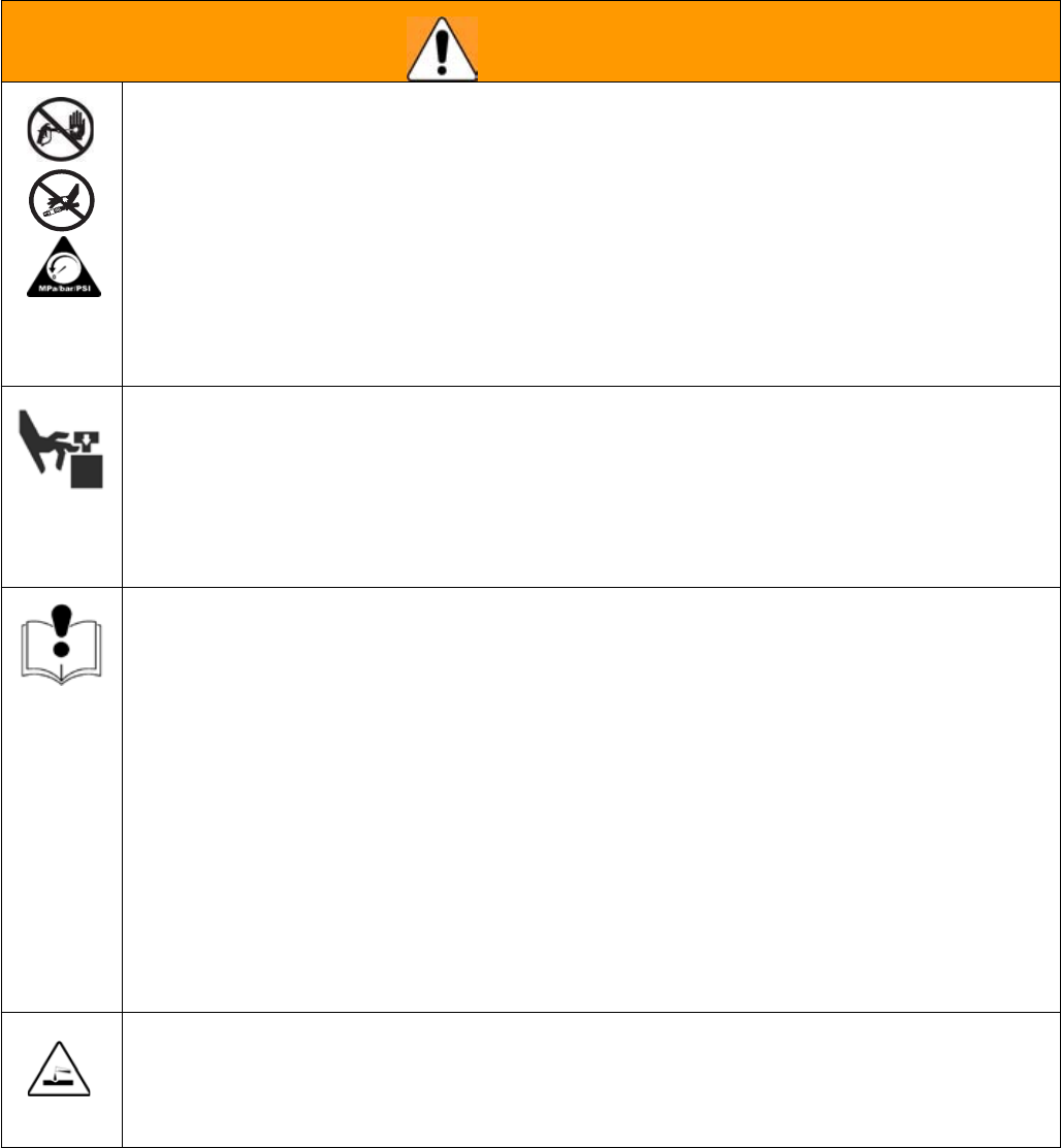
SKIN INJECTION HAZARD
+LJKSUHVVXUHÀXLGIURPJXQKRVHOHDNVRUUXSWXUHGFRPSRQHQWVZLOOSLHUFHVNLQ7KLVPD\ORRN
OLNHMXVWDFXWEXWLWLVDVHULRXVLQMXU\WKDWFDQUHVXOWLQDPSXWDWLRQGet immediate surgical
treatment.
• Do not point gun at anyone or at any part of the body.
• Do not put your hand over the dispense outlet.
'RQRWVWRSRUGHÀHFWOHDNVZLWK\RXUKDQGERG\JORYHRUUDJ
(QJDJHWULJJHUORFNZKHQQRWVSUD\LQJ
• Follow Pressure Relief Procedure in this manual, when you stop spraying and before cleaning,
FKHFNLQJRUVHUYLFLQJHTXLSPHQW
MOVING PARTS HAZARD
0RYLQJSDUWVFDQSLQFKRUDPSXWDWH¿QJHUVDQGRWKHUERG\SDUWV
• Keep clear of moving parts.
• Do not operate equipment with protective guards or covers removed.
3UHVVXUL]HGHTXLSPHQWFDQVWDUWZLWKRXWZDUQLQJ%HIRUHFKHFNLQJPRYLQJRUVHUYLFLQJ
equipment, follow the Pressure Relief Procedure in this manual. Disconnect power or air
supply.
EQUIPMENT MISUSE HAZARD
Misuse can cause death or serious injury.
'RQRWRSHUDWHWKHXQLWZKHQIDWLJXHGRUXQGHUWKHLQÀXHQFHRIGUXJVRUDOFRKRO
'RQRWH[FHHGWKHPD[LPXPZRUNLQJSUHVVXUHRUWHPSHUDWXUHUDWLQJRIWKHORZHVWUDWHGV\VWHP
component. See Technical Data in all equipment manuals.
8VHÀXLGVDQGVROYHQWVWKDWDUHFRPSDWLEOHZLWKHTXLSPHQWZHWWHGSDUWV6HHTechnical Data
LQDOOHTXLSPHQWPDQXDOV5HDGÀXLGDQGVROYHQWPDQXIDFWXUHU¶VZDUQLQJV)RUFRPSOHWH
information about your material, request MSDS forms from distributor or retailer.
&KHFNHTXLSPHQWGDLO\5HSDLURUUHSODFHZRUQRUGDPDJHGSDUWVLPPHGLDWHO\ZLWKJHQXLQH
manufacturer’s replacement parts only.
• Do not alter or modify equipment.
• Use equipment only for its intended purpose. Call your distributor for information.
5RXWHKRVHVDQGFDEOHVDZD\IURPWUDI¿FDUHDVVKDUSHGJHVPRYLQJSDUWVDQGKRWVXUIDFHV
'RQRWNLQNRURYHUEHQGKRVHVRUXVHKRVHVWRSXOOHTXLSPHQW
.HHSFKLOGUHQDQGDQLPDOVDZD\IURPZRUNDUHD
• Comply with all applicable safety regulations.
PRESSURIZED ALUMINUM PARTS HAZARD
'RQRWXVHWULFKORURHWKDQHPHWK\OHQHFKORULGHRWKHUKDORJHQDWHGK\GURFDUERQVROYHQWVRUÀXLGV
containing such solvents in pressurized aluminum equipment. Such use can cause serious chemical
reaction and equipment rupture, and result in death, serious injury, and property damage.
Warnings
GC-1412D 5
Important Safety Information
Methyl Ethyl Ketone Peroxide (MEKP)
MEKP is among the more hazardous materials
found in commercial channels. Proper handling
of the “unstable (reactive)” chemicals presents a
GH¿QLWHFKDOOHQJHWRWKHSODVWLFVLQGXVWU\7KH
KLJKO\UHDFWLYHSURSHUW\ZKLFKPDNHV0(.3
valuable to the plastics industry in producing the
curing reaction of polyester resins and gel-coats
also produces the hazards which require great care
and caution in its storage, transportation, handling,
processing and disposal.
:RUNHUVPXVWEHWKRURXJKO\LQIRUPHGRIWKHKD]DUGV
that may result from improper handling of MEKP,
especially in regards to contamination and heat.
They must be thoroughly instructed regarding the
SURSHUDFWLRQWREHWDNHQLQWKHVWRUDJHXVHDQG
disposal of MEKP and other hazardous materials
used in the laminating operation.
Polyester Resins and Gel-Coats
Spraying and Lamination Operations
GlasCraft recommends that you consult OSHA
Sections 1910.94, 1910.106, 1910.107 and NFPA
No. 33, Chapter 16,17, and NFPA No. 91 for further
guidance.
Spraying materials containing polyester resin and
gel-coats creates potentially harmful mist, vapors and
atomized particulates. Prevent inhalation by providing
VXI¿FLHQWYHQWLODWLRQDQGWKHXVHRIUHVSLUDWRUVLQWKH
ZRUNDUHD
Read the material manufacturer’s warnings and ma-
WHULDO06'6WRNQRZVSHFL¿FKD]DUGVDQGSUHFDXWLRQV
related to polyester resins and gel-coats.
To prevent contact with polyester resins and gel-
coats, appropriate personal protective equipment,
including chemically impermeable gloves, boots,
aprons and goggles are required for everyone in the
ZRUNDUHD
0(.3LVÀDPPDEOHDQGSRWHQWLDOO\H[SORVLYH
as well as potentially damaging to the eyes and
skin.
Read material manufacturer’s warnings and
PDWHULDO06'6WRNQRZVSHFL¿FKD]DUGVDQG
precautions related to MEKP.
Contaminated MEKP can become explosive.
Prevent contamination of MEKP with other materi-
als, which includes, but is not limited to polyester
overspray, polymerization accelerators and promot-
ers, and non-stainless metals. Even small amounts
RIFRQWDPLQDWHVFDQPDNH0(.3H[SORVLYH7KLVUH-
action may start slowly, and gradually build-up heat,
ZKLFKFDQDFFHOHUDWHXQWLO¿UHRUDQH[SORVLRQUHVXOW
7KLVSURFHVVFDQWDNHIURPVHFRQGVWRGD\V
Heat applied to MEKP, or heat build-up from con-
tamination reactions can cause it to reach what is
called its Self-Accelerating Decompisition Tempera-
WXUH6$'7ZKLFKFDQFDXVH¿UHRUH[SORVLRQ
Spills should be promptly removed, so no residues
remain. Spillage can heat up to the point of self-
ignition. Dispose in accordance with manufacture’s
recommendation.
Store MEKP in a cool, dry and well-ventilated area
in the original containers away from direct sunlight
and away from other chemicals. It is strongly recom-
mended that the storage temperature remain below
86° F (30° C). Heat will increase the potential for ex-
plosive decomposition. Refer to NFPA 432.
.HHS0(.3DZD\IURPKHDWVSDUNVDQGRSHQ
ÀDPHV
Remove all accumulations of overspray, FRP sand-
ings, etc. from the building as they occur. If this waste
LVDOORZHGWREXLOGXSVSLOODJHRIFDWDO\VWLVPRUHOLNHO\
WRVWDUWD¿UH
If cleaning solvents are required, read material
PDQXIDFWXUH¶VZDUQLQJVDQGPDWHULDO06'6WRNQRZ
VSHFL¿FKD]DUGVDQGSUHFDXWLRQV*ODV&UDIWUHFRP-
PHQGVWKDWFOHDQXSVROYHQWVEHQRQÀDPPDEOH
Current catalysts are premixed and do not require
any diluents. GlasCraft strongly recommends that dilu-
ents not be used. Diluants add to the possibility of con-
taminates entering the catalyst system. Never dilute
MEKP with acetone or any solvent since this can pro-
GXFH DQ H[WUHPHO\ VKRFNVHQVLWLYH FRPSRXQG ZKLFK
can explode.
Use only original equipment or equivalent parts
IURP*ODV&UDIWLQWKHFDWDO\VWV\VWHPLHKRVHV¿W-
tings, etc.) because a hazardous chemical reaction
may result between substituted parts and MEKP.
To prevent contact with MEKP, appropriate personal
protective equipment, including chemically imperme-
able gloves, boots, aprons and goggles are required
IRUHYHU\RQHLQWKHZRUNDUHD
6 GC-1412D
This equipment needs to be grounded.
Ground the spray gun through connection to a
*ODV&UDIWDSSURYHGJURXQGHGÀXLGVXSSO\KRVH
&KHFN\RXUORFDOHOHFWULFDOFRGHDQGUHODWHGPDQXDOV
for detailed grounding instructions of all equipment in
WKHZRUNDUHD
A grounding wire and clamp are provided,
assembly p/n 17440-00 with all FRP equipment.
The mast must be secured in the retracted position
before transporting the system to prevent swinging of the
mast and system imbalance.
Grounding
Mask FilterEar
GC-1412D 7
6\VWHP$VVHPEO\
$Q\PRXQWLQJRSWLRQFDUWPDVWERRPÀRRUPRXQW
or wall mount etc. should be completely assembled
before starting the following steps.
Tools Required:
6WDQGDUGZUHQFKVRFNHWVHW
6WDQGDUGKH[NH\VHW
3) Tape measure
All “Required tools” are standard sizes.
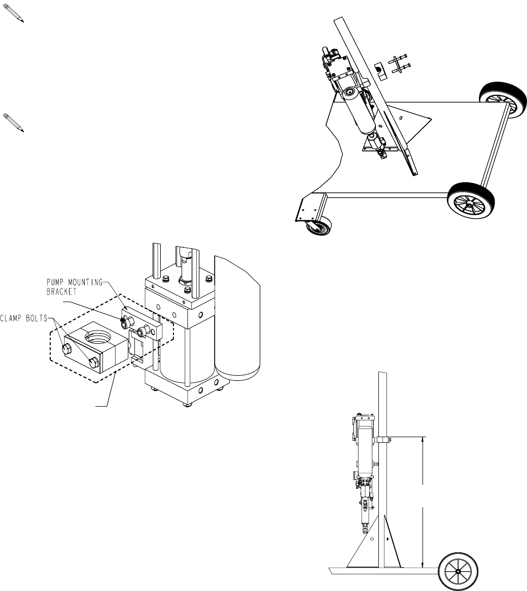
1. Loosen clamp bolts to expose pump mounting
EUDFNHW$WWDFKSXPSPRXQWLQJEUDFNHWWRWKHDLU
PRWRU8VHWKUHDGORFNHURQWKHWKUHDGVDQGWLJKWHQ
KH[EROWVDVWLJKWDVSRVVLEOHLQKH[NH\
2. a. Stand the pump assembly next to the mast and
LQVWDOOWKHSXPSPRXQWLQJEUDFNHW
E Lift to desired height with the pump assembly facing
the front of the cart as shown, approximately 41in.
from the top of the cart to the top of the pump mount-
LQJEUDFNHW8VHLQZUHQFKDQGWLJKWHQDVWLJKWDV
possible.
19890-00
HEX BOLTS
41in./104 cm.
APPROX.
Set-Up
8 GC-1412D
3. Attach air manifold p/n 23555-00 to the air motor.
4. 0RXQWFDWDO\VWERWWOHEUDFNHWZLWKVXSSOLHGXEROWV
p/n CP-126, 34in. from the top of the cart, to the top
RIWKHFDWDO\VWEUDFNHWDQGSDUDOOHOZLWKWKHPDWHULDO
pump.
5.,QVWDOOWKHFDWDO\VWMXJZLWKWKHHOERZ¿WWLQJIDFLQJWKH
front of the unit.
6. Install tubing p/n 9704-11 from the catalyst jug to the
LQOHW¿WWLQJRQWKHFDWDO\VWSXPS3XVKWKHWXELQJLQWR
WKHFDWDO\VWMXJVXSSO\¿WWLQJXQWLOLWVWRSV8VLQJWZR
proper sized wrenches, carefully tighten the compres-
VLRQQXWWRORFNGRZQWKHWXELQJ
The tubing must be cut to desired length, giving a
natural gravity feed supply to the slave pump.
34in./86cm.
APPROX.
Set-Up
GC-1412D 9
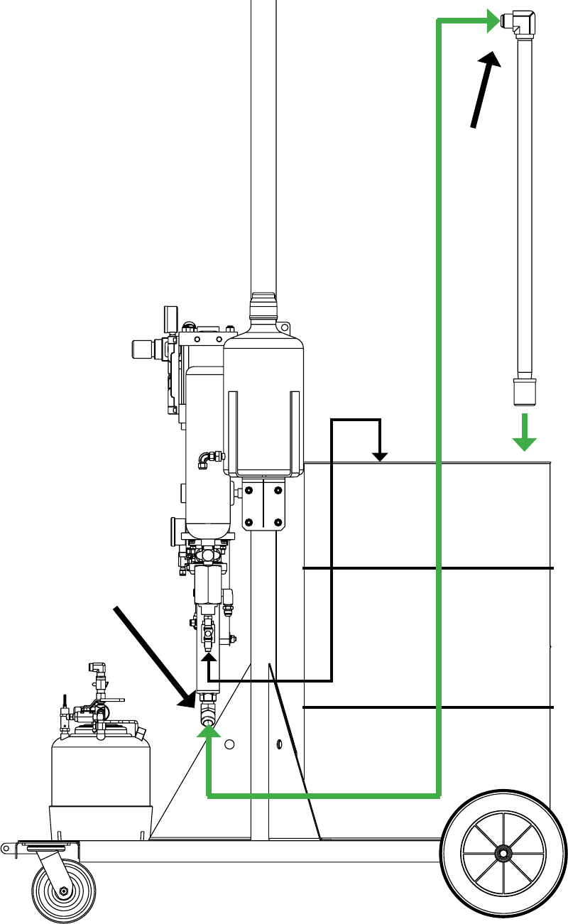
7. Remove the pump inlet saftey cap and drain the
testing oil into an open container. Attach green
SLFNXSKRVHWRWKHSXPSLQOHW¿WWLQJDQGWLJKWHQ
8. $WWDFKJUHHQSLFNXSKRVHWRWKHSLFNXSWXEH
FOR INDY CHOPPER GUN INSTALLATION BEGIN
STEPS 9 THROUGH 13 .
FOR FORMULA CHOPPER GUN INSTALLATION
BEGIN STEPS 14 THROUGH 18.
7.
8.
Set-Up
10 GC-1412D
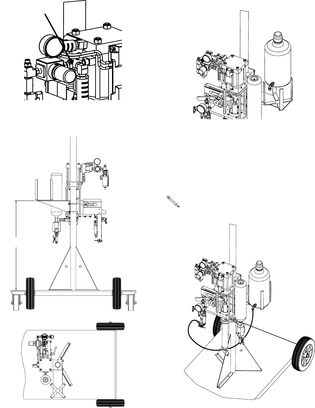
9. a. Lay all of the hoses out straight.
E ,QVWDOO¿WWLQJVSQ¶VDQG
using PTFE tape on the NPT threads ONLY.
c. Install the assembly from step “b” to the
material hose and attach the 3 ft. whip
hose p/n H42503 to the other end.
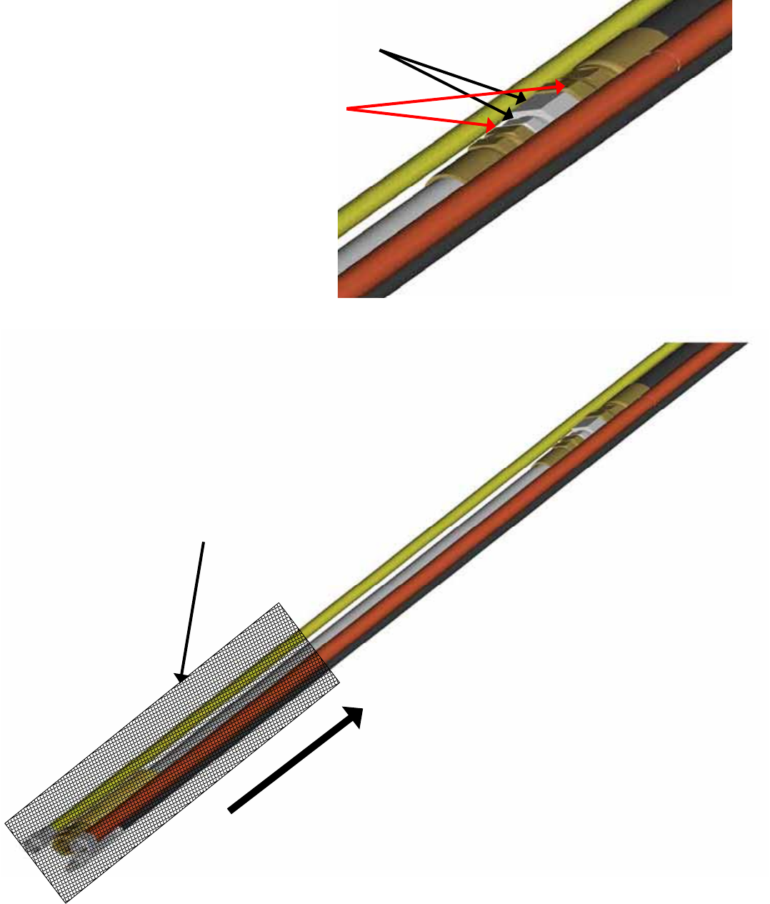
10. 6OLGHWKHVXSSOLHG³EODFNVFXIIMDFNHW´SQ)0
over the hose assembly and leave it loose until the
hoses are attached to the gun.
Indy Chopper Gun Option
Set-Up
GC-1412D 11
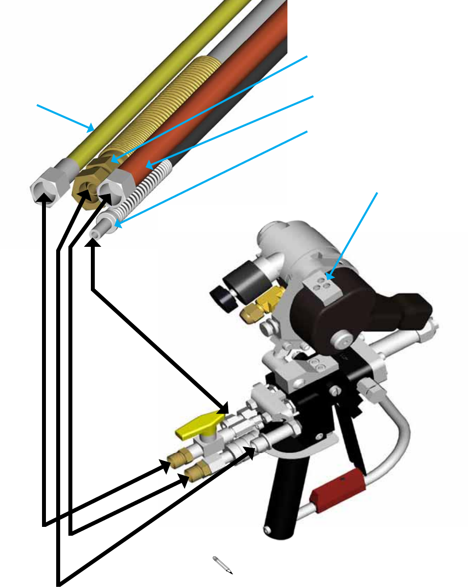
11. a. Attach the hoses to the gun.
Egroup the hoses together as shown and wrap
them with tape about every 2 feet.
c. 6WDUWDSSUR[LQEDFNIURPWKHJXQDQGWDSH
WKHHQGRIWKH³EODFNVFXIIMDFNHW´ZLWKEODFN
WDSH6SUHDGWKH³EODFNVFXIIMDFNHW´RXWVR
LW¿WVVQXJDURXQGWKHKRVHVDQGWDSHWKH
RWKHUHQGZLWKEODFNWDSH
Yellow Solvent Hose
p/n 236
%ODFN0DWHULDO:KLS+RVH
p/n 21694-25
Red Chopper Air Hose
p/n 17798-25
Stainless Steel Catalyst Hose
p/n 20190-00
Fiberglass Roving Ports
The B-410 chopper is shown for reference ONLY.
Refer to the chopper manual for optional snouts
and adjustments.
Set-Up
12 GC-1412D
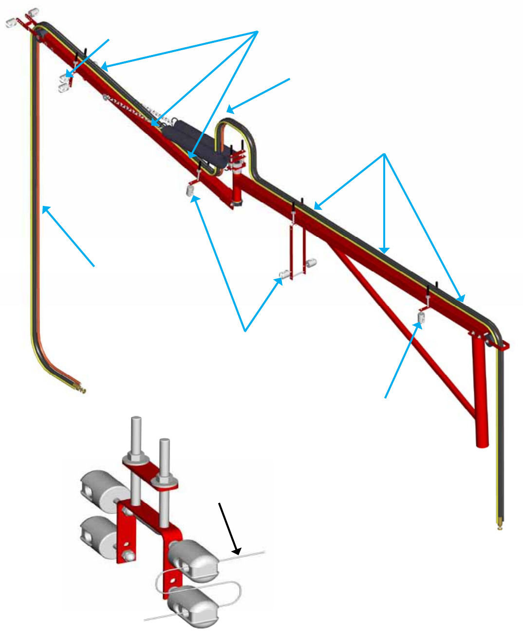
12. Start At This End
Route the four hoses from the
JXQWKURXJKWKHERRPDVVKRZQ
XVLQJELQGLQJVWUDSVSQ
WRVHFXUHWKHKRVHVWRWKHERRP
5RXWHWKHIRXUKRVHVEHWZHHQ
the two springs.
Secure the four hoses to
WKHERRPZLWKELQGLQJVWUDSV
SQ
Secure the four hoses to
WKHERRPZLWKELQGLQJVWUDSV
SQ
Start Fiberglass Roving Here
5RXWH¿EHUJODVVURYLQJVWUDQGV
WKURXJKWKHURYLQJJXLGHV
5RXWH¿EHUJODVVURYLQJVWUDQGV
WKURXJKWKHURYLQJJXLGHV
See Detail C
Detail C
5RXWH¿EHUJODVVURYLQJ
strands through the
URYLQJEUHDNJXLGHV
as shown
From Spool
To Gun
Set-Up
GC-1412D 13
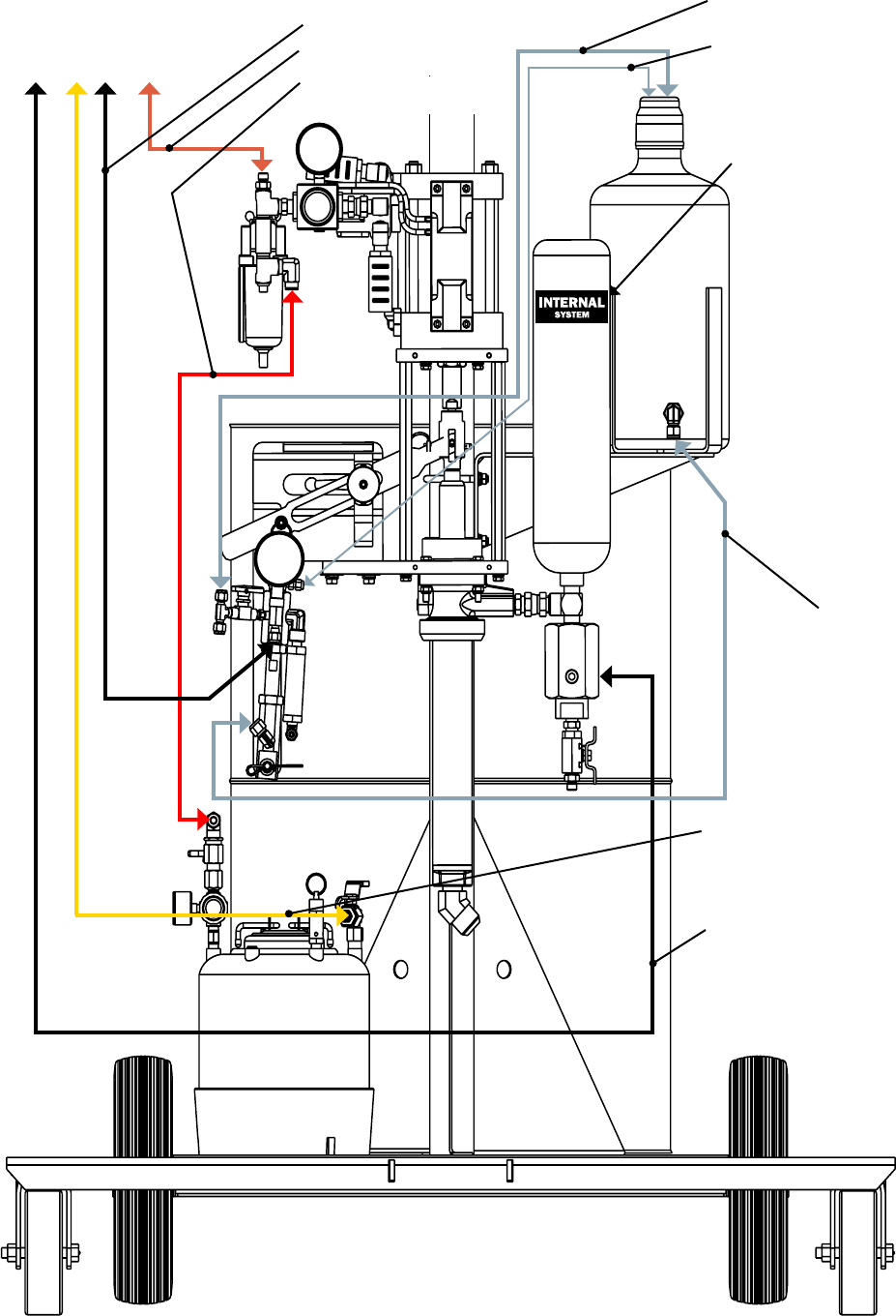
TO BOOM
13. Attach the hoses to the unit as shown.
Yellow Solvent Hose
%ODFN0DWHULDO+RVH
Clear Tubing 3/8 in.
Stainless Catalyst Hose
Red Air Hose
Red Solvent Air
Tubing
Clear Tubing 1/4 in.
Clear Tubing 1/8 in.
Place decal here
Set-Up

14 GC-1412D
14. a. Lay all of the hoses and trigger air tubing out straight.
E ,QVWDOO¿WWLQJVSQ¶VDQG
using PTFE tape on the NPT threads ONLY.
c. Install the assembly from step “B” to the
material hose and attach the 3 ft. whip
hose p/n H42503 to the other end.
15. 6OLGHWKHVXSSOLHG³EODFNVFXIIMDFNHW´SQ)0
over the hose assembly and leave it loose until the
hoses are attached to the gun.
Formula Chopper Gun Option
Set-Up
GC-1412D 15
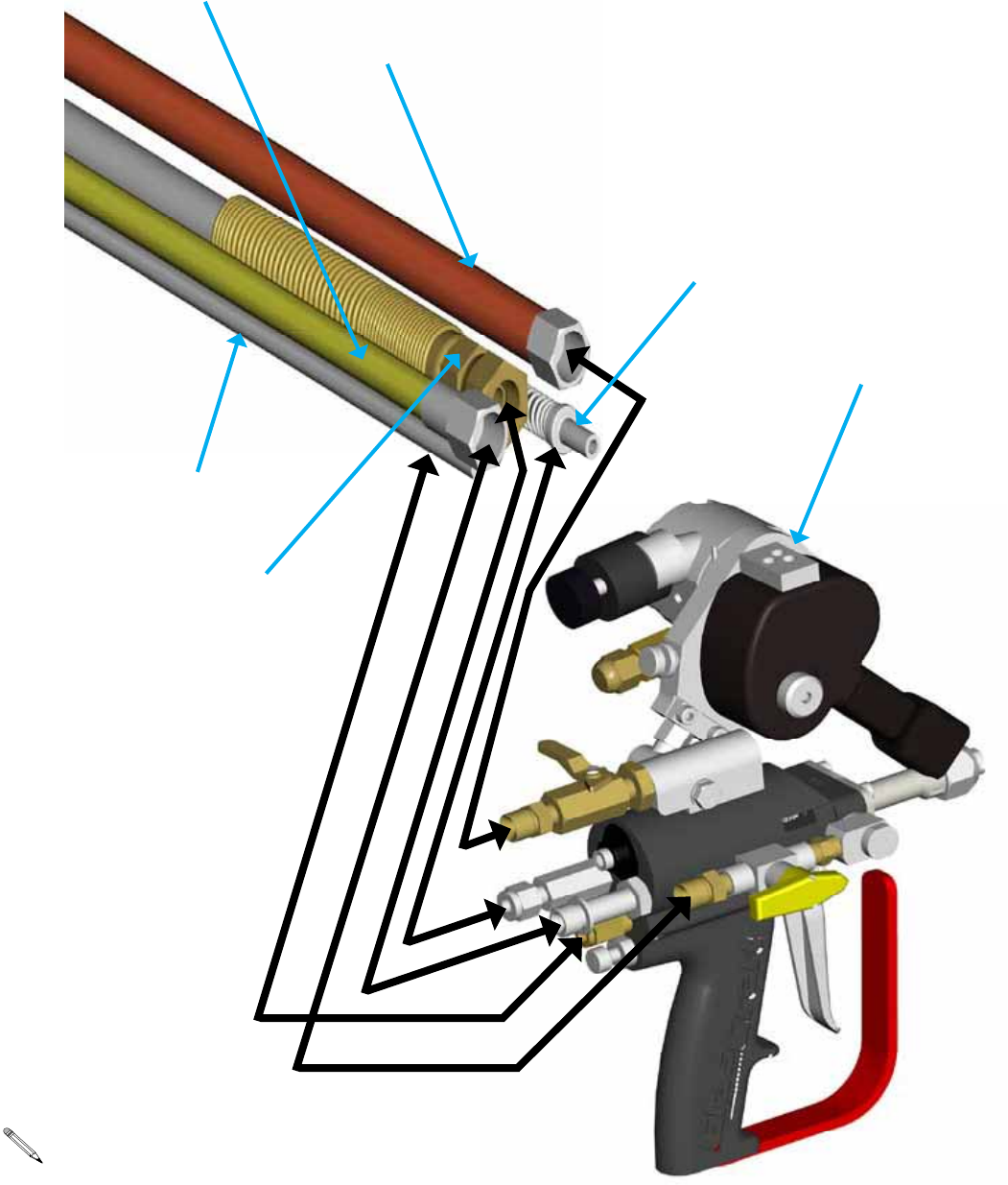
Stainless Steel Catalyst Hose
p/n 20190-00
Red Chopper Air Hose
p/n 17798-25
%ODFN0DWHULDO:KLS+RVH
p/n 21694-25
Yellow Solvent Hose
p/n 236
Trigger Air Tubing
p/n 9704-03
Fiberglass Roving Ports
16. a. Attach the hoses to the gun.
EGroup the hoses together as shown and wrap
them with tape about every 2 feet.
c. 6WDUWDSSUR[LQEDFNIURPWKHJXQDQGWDSH
WKHHQGRIWKH³EODFNVFXIIMDFNHW´ZLWKEODFN
WDSH6SUHDGWKH³EODFNVFXIIMDFNHW´RXWVR
LW¿WVVQXJDURXQGWKHKRVHVDQGWDSHWKH
RWKHUHQGZLWKEODFNWDSH
The B-410 chopper is shown for reference ONLY.
Refer to the chopper manual for optional snouts
and adjustments.
Set-Up
16 GC-1412D
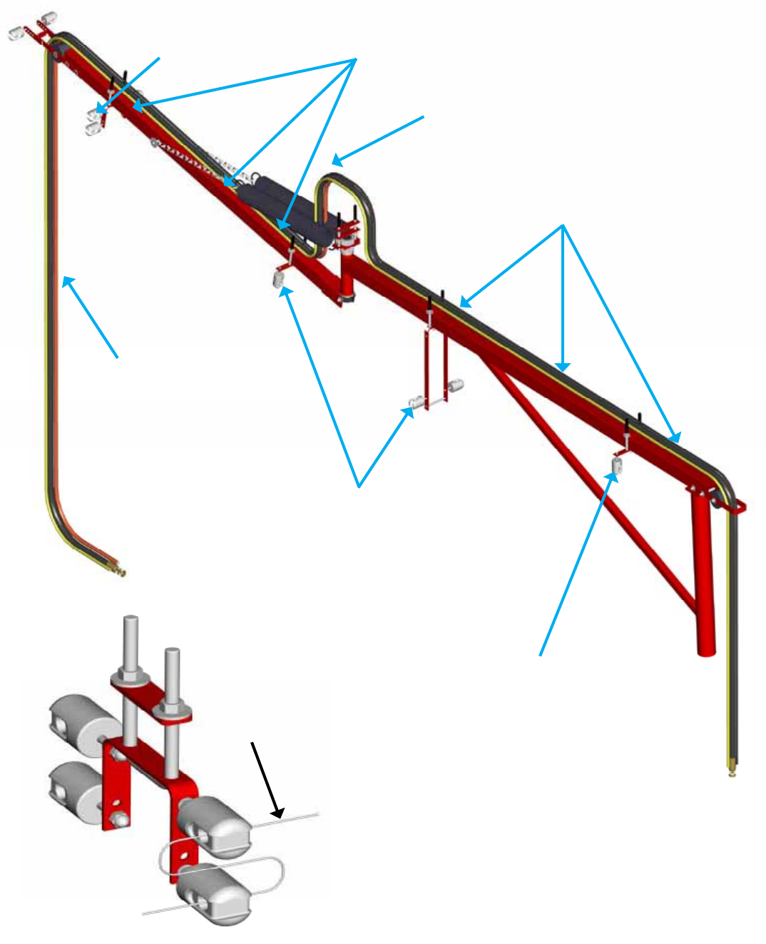
17. Start At This End
5RXWHWKH¿YHKRVHVIURPWKH
JXQWKURXJKWKHERRPDVVKRZQ
XVLQJELQGLQJVWUDSVSQ
WRVHFXUHWKHKRVHVWRWKHERRP
5RXWHWKH¿YHKRVHVEHWZHHQ
the two springs.
6HFXUHWKH¿YHKRVHVWRWKH
ERRPZLWKELQGLQJVWUDSV
SQ
6HFXUHWKH¿YHKRVHVWRWKH
ERRPZLWKELQGLQJVWUDSV
SQ
Start Fiberglass Roving Here
5RXWH¿EHUJODVVURYLQJVWUDQGV
WKURXJKWKHURYLQJJXLGHV
5RXWH¿EHUJODVVURYLQJVWUDQGV
WKURXJKWKHURYLQJJXLGHV
See Detail C
Detail C
5RXWH¿EHUJODVVURYLQJ
strands through the
URYLQJEUHDNJXLGHV
as shown
From Spool
To Gun
Set-Up
GC-1412D 17
TO BOOM
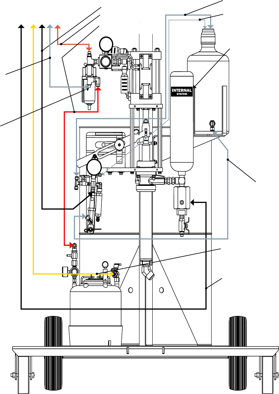
18. Attach the hoses to the unit as shown.
Yellow Solvent Hose
%ODFN0DWHULDO+RVH
Stainless Catalyst Hose
Red Air Hose
Red Solvent Air
Tubing
Remove plug
and install elbow
¿WWLQJSQ
Trigger Air
Clear Tubing
Clear Tubing 3/8 in.
Clear Tubing 1/4 in.
Clear Tubing 1/8 in.
Place decal here
Set-Up
18 GC-1412D
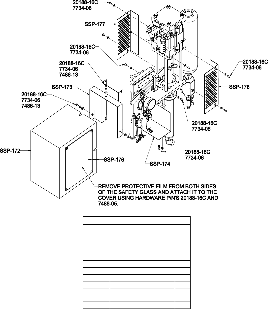
SSP-175 Safety Guard Kit
SSP-175
Part
1XPEHU Description Qty.
SSP-172 SURROUND GUARD 1
SSP-173 LEFT PUMP GUARD 1
SSP-174 ANGLE BRACKET 1
SSP-176 GUARD WINDOW 1
SSP-177 RIGHT PUMP GUARD 1
SSP-178 RIGHT FRONT PUMP GUARD 1
20188-16C SCREW 17
7486-05 FENDER WASHER 4
7486-13 WASHER 3
7734-06 LOCK WASHER 13
Set-Up
GC-1412D 19
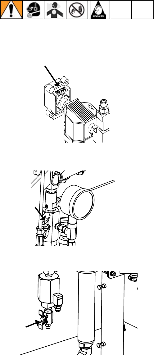
7RUHOLHYHÀXLGDQGDLUSUHVVXUHV
1. Push down Yellow slide valve, P/N 21402-00 to bleed
off air to system.
2. Open P/N 21228-00 on catalyst pump to recirculation
position.
3. Open P/N 21192-00 on bottom of material pump.
Pressure Relief Procedure
20 GC-1412D
The following assumes that all connections are tight.
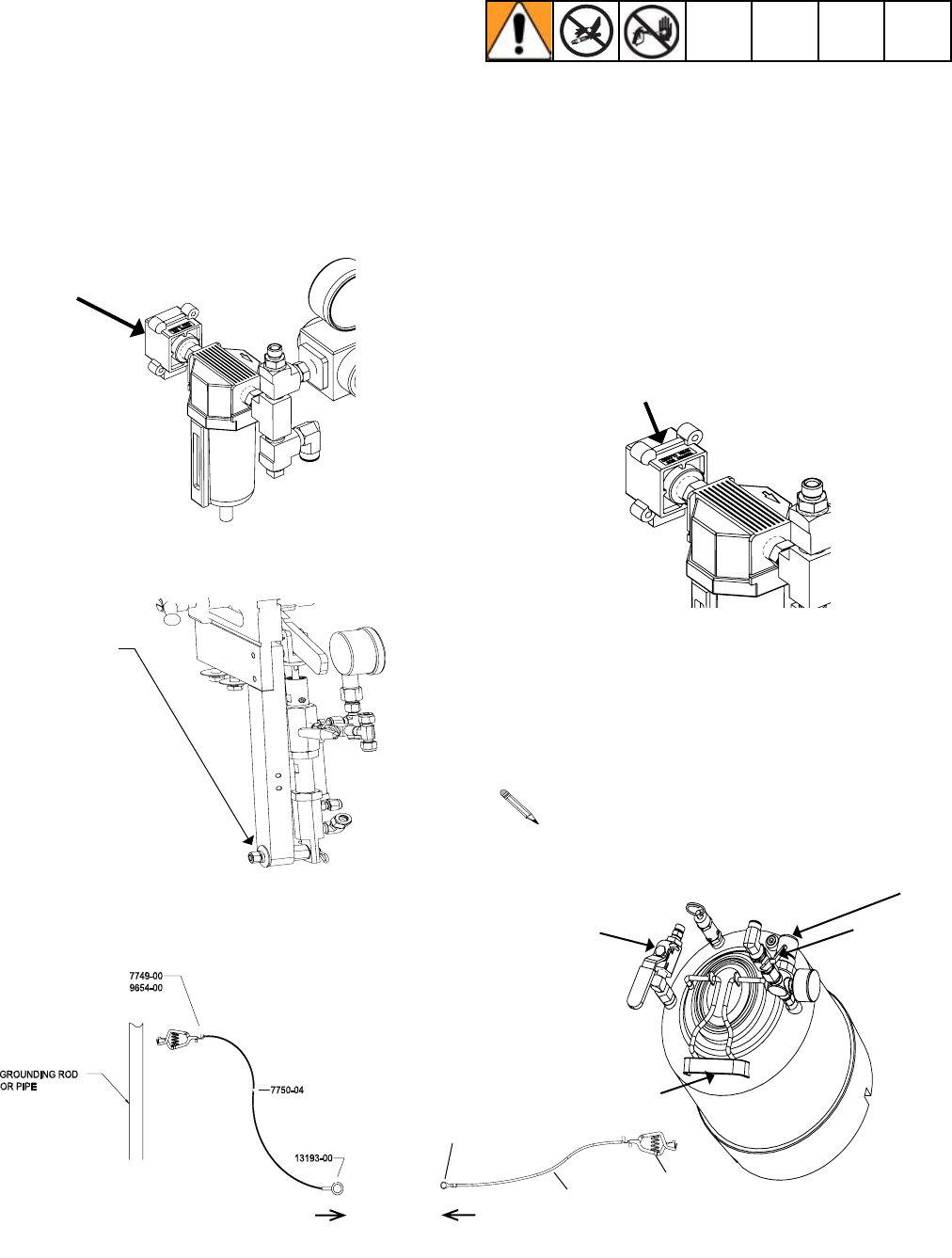
System Start-Up Instructions
1. Select a clean dry air supply.
2. Attach a 3/8” or larger air hose to the Air Manifold
Inlet. 'RQRWXVHTXLFNGLVFRQQHFW¿WWLQJV
3. Attach grounding clamp assembly, P/N 17440-00, to
the slave pump.
Attach Here
4. Securely attach Clamp, P/N 7749-00, to permanently
grounded rod or pipe.
Before turning on main air, check all On/Off Ball Valves,
making certain all Valves are in the “Off” position and set
all regulators in their “Off” position. (Turn knob counter-
clockwise for OFF or reduced pressure setting.)
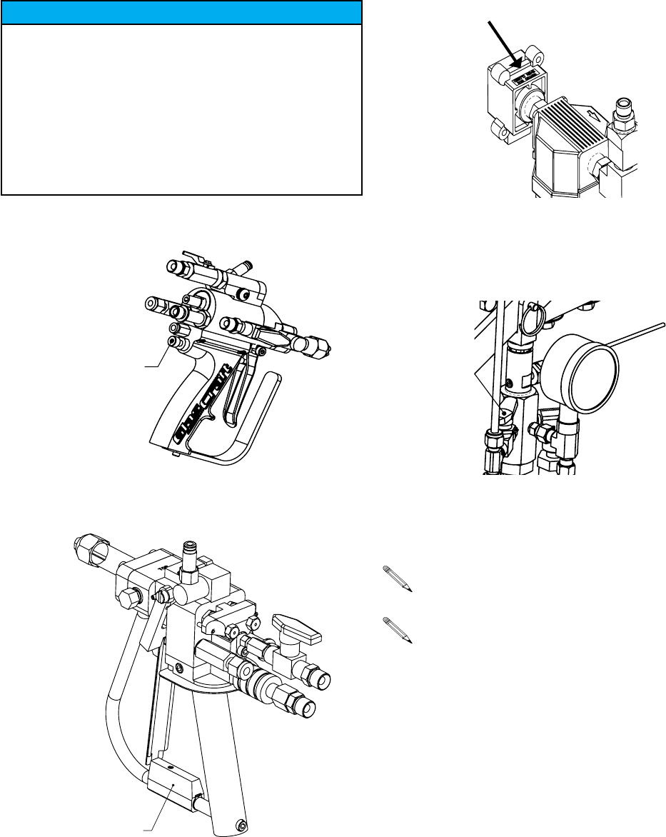
5. Place the mixing element straight into the front gun
housing. (refer to spray gun user manual)
6. Place the retaining nut along with the spray tip and
spray tip spacer onto the gun housing. (refer to spray
gun user manual)
7. Push the slide valve to the open position.
8. 2SHQWKHDLUYDOYHSQRQWKHVROYHQWWDQNDQG
adjust the solvent pressure to 90 PSI (6.2 bar). Open
WKHEDOOYDOYHSQRQWKHVROYHQWWDQN1H[W
open ball valve p/n 23518-00 on the gun to verify that
VROYHQWZLOOÀRZRXWRIWKHIURQWRIWKHJXQWKURXJKWKH
dispense tip, then close the valve.
Do not exceed 20 PSI (1.4 bar)on the material
UHJXODWRUXQWLODVWHDG\PDWHULDOÀRZKDVEHHQ
established.
Start-Up
TO SLAVE PUMP
Valve
18470-00 Ball valve
3165
Regulator
Attach
Here
7750-04
13193-00
7749-00
9654-00
GC-1412D 21
SSP-160-01
If you are using the optional Formula gun set the
trigger air regulator to 100 PSI (7 bar). The trigger
air IS NOT to exceed 100 PSI (7 bar).
10. Trigger the Gun into a container until all the air is
purged from the resin side of the system. It may be
QHFHVVDU\WR+DQGVWURNHWKH&DWDO\VW3XPS
several times while the gun is triggered to positively
deliver a steady stream of catalyst. Let go of the
WULJJHUDQGKDQGVWURNHSXPSDJDLQWRGHYHORS
300-400 PSI (21-28 bar). “STOP”
a.6ROYHQWÀXVKWKHJXQ³6723´
E Once primed, increase the resin PSI until a desired
spray pattern is achieved.
c. After all pressure adjustments have been completed, a
¿QDOVSUD\WHVWVKRXOGEHPDGH6SUD\DWHVWVKRW
sample on a clean piece of paper. The shot should be
DSSUR[LPDWHO\¿YHIHHWLQOHQJWK<RXFDQQRZFKHFN
desired gel times and uniformity of curing.
d. Flush the gun thoroughly with solvent after use.
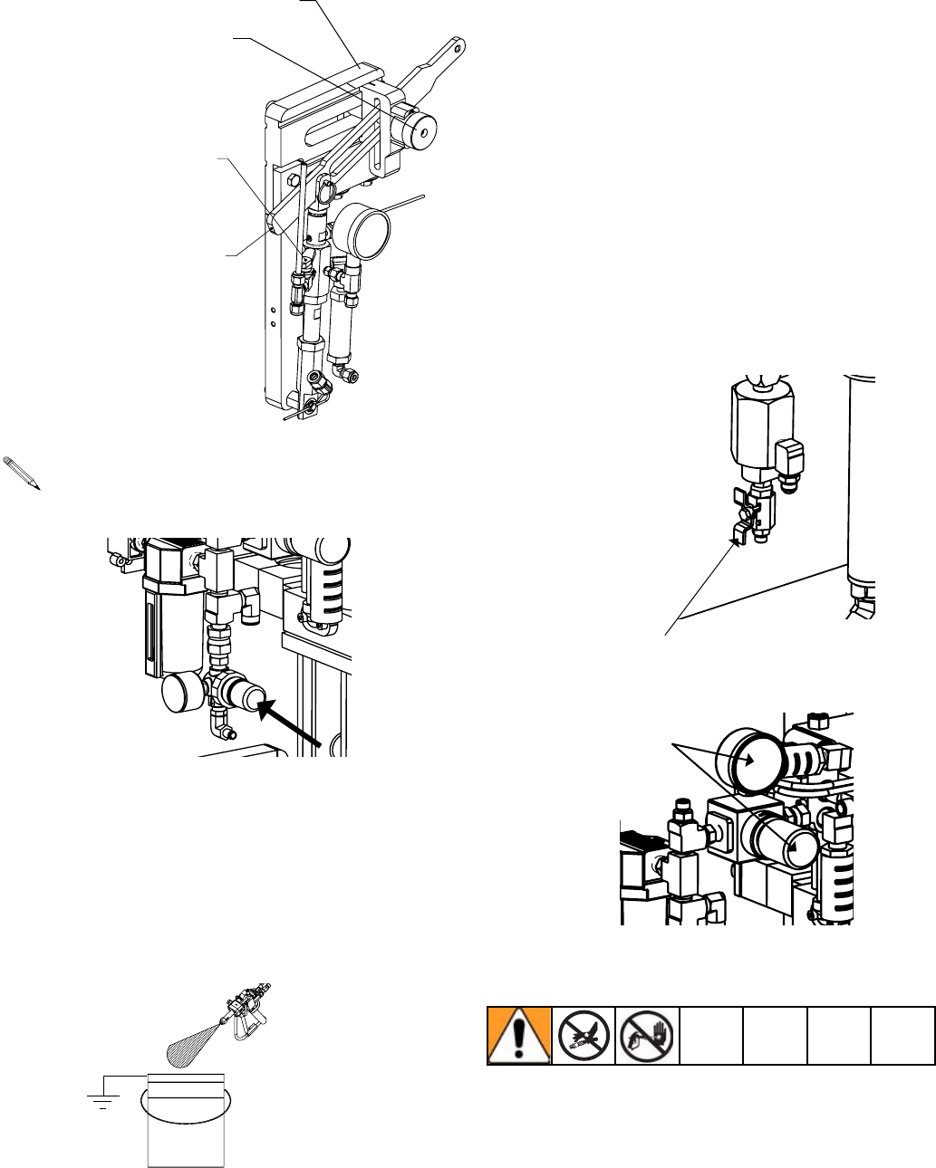
11. 0DNHVXUHWKDWWKHUHVLQSXPSUHFLUFXODWLRQYDOYH
LV³RII´DQGWKDWWKHE\SDVVKRVHLVLQEDFNLQWKH
the drum. Adjust the resin pump regulator to 20 PSI
(1.4 bar) the pump will start to slowly cycle. Allow the
pump to “load” the cycle rate should slow indicating the
pump is primed. Close the recirculation valve.
Recirculation Valve
Resin Pump Regulator
Do not exceed 20 PSI (1.4 bar) pressure on the Material
5HJXODWRUXQWLOVWHDG\PDWHULDOÀRZKDVEHHQHVWDEOLVKHG
E Turn the slave pump
yellow ball valve to the
open position.
c. Hand prime the pump
until a steady stream of cat-
DO\VWÀRZVEDFNWRWKHERWWOH
d. Close the ball valve. Hand
VWURNHWKHSXPSXQWLOLWGHYHO
opes 300-400 PSI (21-28 bar).
9a. Pull and rotate Pivot
NQREWRGLVHQJDJHWKHFDWDO\VW
drive arm.
Start-Up
22 GC-1412D
Shut-Down Instructions
Due to the different O-Ring materials and lubricants
used in the Guns never submerge or soak any
dispense gun in any type of solvent!
Submerging or soaking any Gun will immediately void
the Gun warranty.
1. $FWLYDWHWULJJHUORFNWRVWRSWKHWULJJHUIURPEHLQJ
activated. Refer to gun manuals if needed.
Formula Gun
Indy Gun
2. Push down the yellow slide valve, P/N 21402-00 on the
inlet air to bleed off air on system.
3. Turn catalyst yellow ball valve, P/N 21228-00 to Open
/ Recirculation position to dump psi. and close the valve.
4. Pressure should be maintained on the resin hose.
If you are using the Indy gun install the night plug
p/n 23527-00.
Refer to gun manuals for service and maintenance.
Push in and rotate
WULJJHUORFNSQ
23774-00 to stop
the trigger from being
activated.
5RWDWHWULJJHUORFN
to stop the trigger
from being activated.
Notice
Shut-down

GC-1412D 23
Parts
Model - Internal Mix Fiberglass Roving Chopper System
0DWHULDO6SUD\1R]]OHV
See gun manuals for spray tip options.
Standard Equipment
Part
1XPEHU Description
SSP-160-01 SUPER CATALYST SLAVE PUMP ASSEMBLY
GAM-268-01 MATERIAL PUMP PICK-UP KIT
21694-25 MATERIAL HOSE ASSEMBLY, 25 FT.
17440-00 GROUNDING CLAMP ASSEMBLY
23555-00 AIR MANIFOLD
17798-25 AIR HOSE 25 FT.
20190-00 CATALYST HOSE 25 FT.
236 SOLVENT HOSE 25 FT.
20794-01 SOLVENT TANK
19890-01 MOUNTING CLAMP
770 / 754-1 / 750-01 CART MAST & BOOM
H42503 MATERIAL WHIP HOSE 3FT.
GC-1412 MANUALS
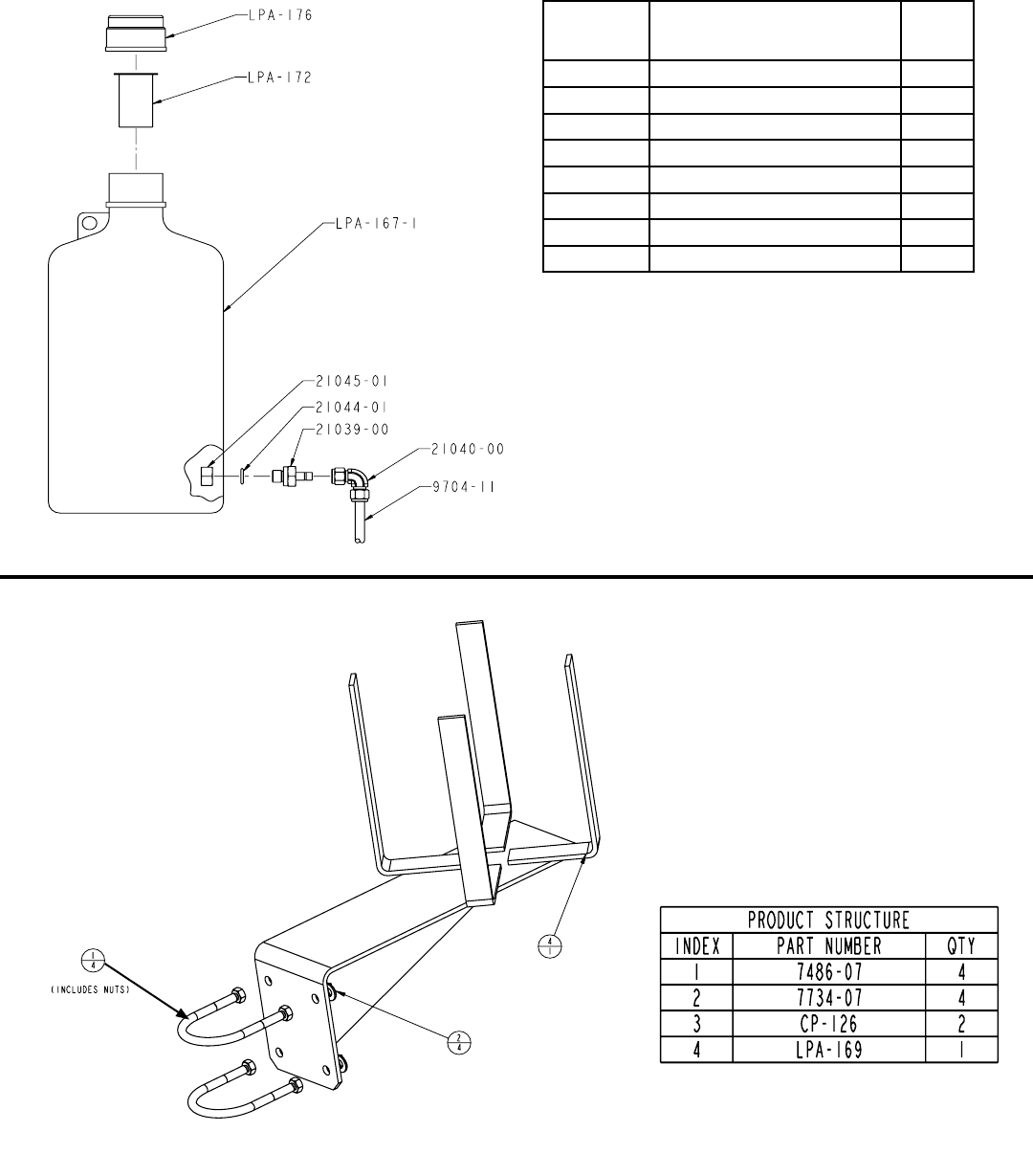
LPA-165 CATALYST BOTTLE
LPA-170 CATALYST BOTTLE BRACKET
9704-03 TRIGGER AIR TUBING (1/4in. CLEAR, 28ft. FORMULA GUN ONLY)
Pump Options
Part
1XPEHU Description
20864-05 0$7(5,$/3803$66(0%/<5$7,2
21780-01 0$7(5,$/3803$66(0%/<5$7,2
22026-01 0$7(5,$/3803$66(0%/<5$7,2
24 GC-1412D
REVISION N
Part
1XPEHU Description Qty.
LPA-167-1 BOTTLE 1
LPA-172 SCREEN 1
LPA-176 CAP 1
21039-00 TUBE ADAPTER 1
21040-00 ELBOW FITTING 1
21044-01 SEAL 1
21045-01 HEX NUT 1
9704-11 TUBING 5
LPA-165 Bottle
/3$&DWDO\VW%RWWOH%UDFNHW
6XE$VVHPEO\'UDZLQJV
REVISION B
GC-1412D 25
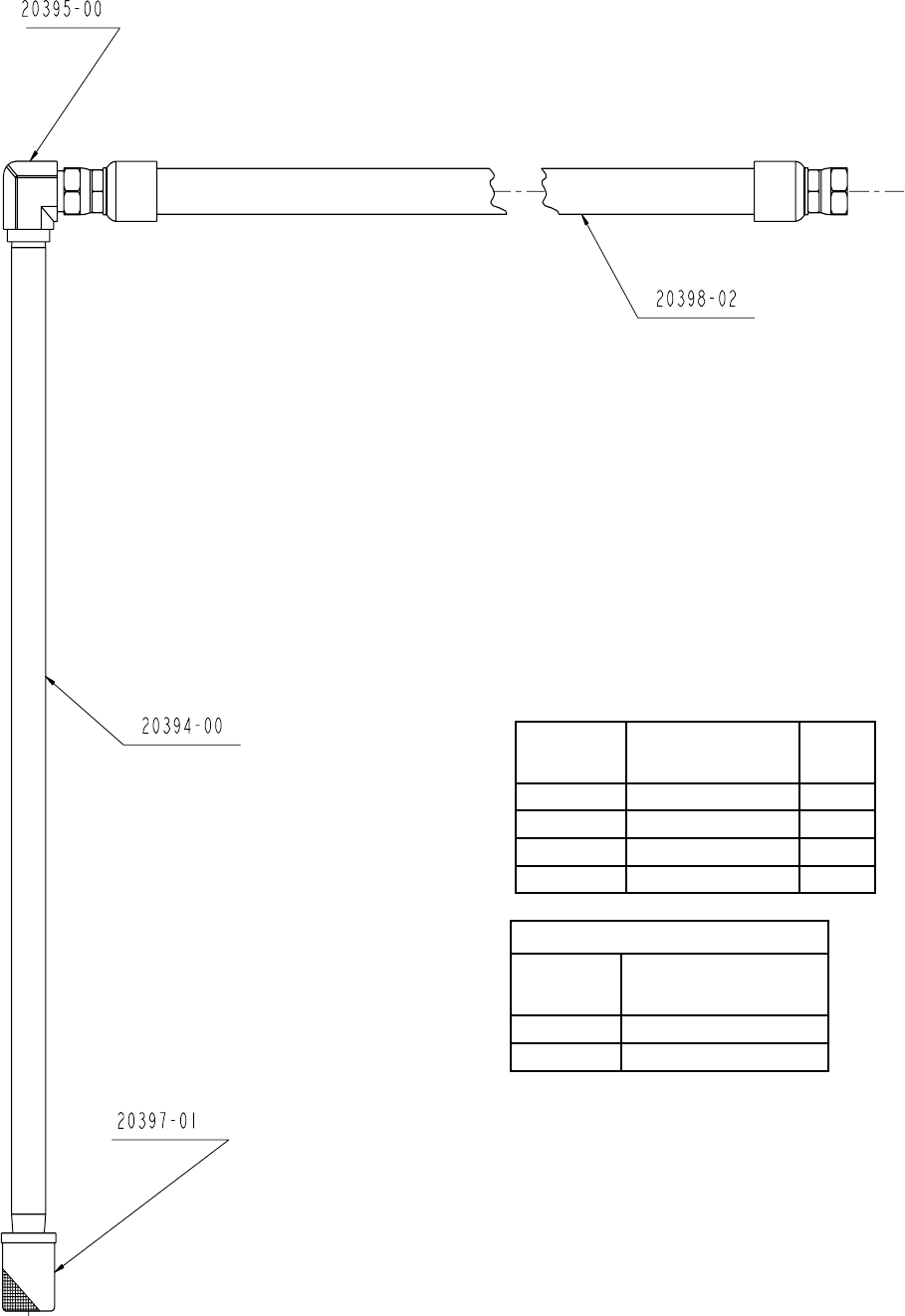
REVISION D
Part
1XPEHU Description Qty.
20394-00 PICK-UP TUBE 1
20395-00 ELBOW FITTING 1
20397-01 30 MESH FILTER 1
20398-02 MATERIAL HOSE 1
Filter Options
Part
1XPEHU Description
20397-02 100 MESH
20397-03 50 MESH
GAM-268-01 Material Pick-Up Kit
6XE$VVHPEO\'UDZLQJV
26 GC-1412D
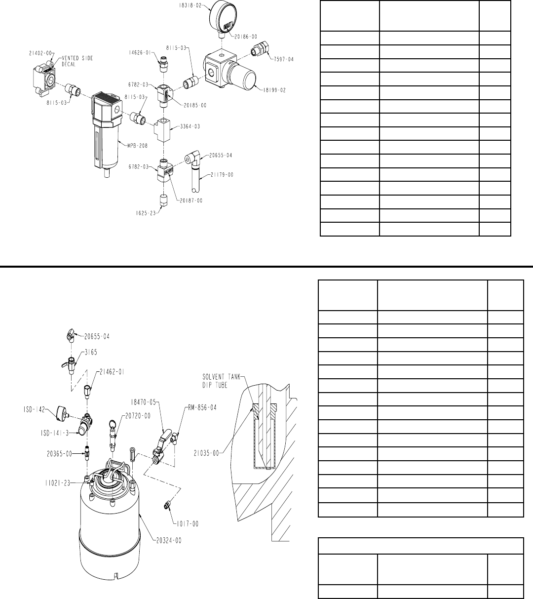
REVISION C
Part
1XPEHU Description Qty.
MPB-208 AIR FILTER 1
14626-01 FITTING 1
1625-23 PIPE PLUG 1
18199-02 AIR REGULATOR 1
18318-02 AIR GAUGE 1
20185-00 CHOPPER DECAL 1
20186-00 MAT’L DECAL 1
20187-00 SOLVENT DECAL 1
20655-04 ELBOW FITTING 1
21179-00 TUBING 10
21402-00 LOCKOUT VALVE 1
3364-03 PIPE TEE 1
6782-03 PIPE TEE 2
7597-04 SWIVEL FITTING 1
8115-03 NIPPLE FITTING 3
23555-00 Air Manifold
6ROYHQW7DQN
6XE$VVHPEO\'UDZLQJV
Part
1XPEHU Description Qty.
ISD-141-3 MINI REGULATOR 1
ISD-142 SOLVENT POT GAUGE 1
RM-856-04 ELBOW FITTING 1
1017-00 FITTING 1
11021-23 PIPE PLUG 1
18470-05 BALL VALVE 1
20324-00 SOLVENT TANK 1
20365-00 RELIEF VALVE 1
20655-04 ELBOW FITTING 1
20720-00 PRESSURE RELIEF VALVE 1
21035-00 PICK-UP STRAINER 1
21044-06 SILICONE O-RING 1
21462-01 FITTING 1
3165 BALL VALVE 1
17440-00 GROUNDING CLAMP ASSY. 1
Optional
Part
1XPEHU Description Qty.
13867-68 EPR O-RING 1
REVISION D
GC-1412D 27
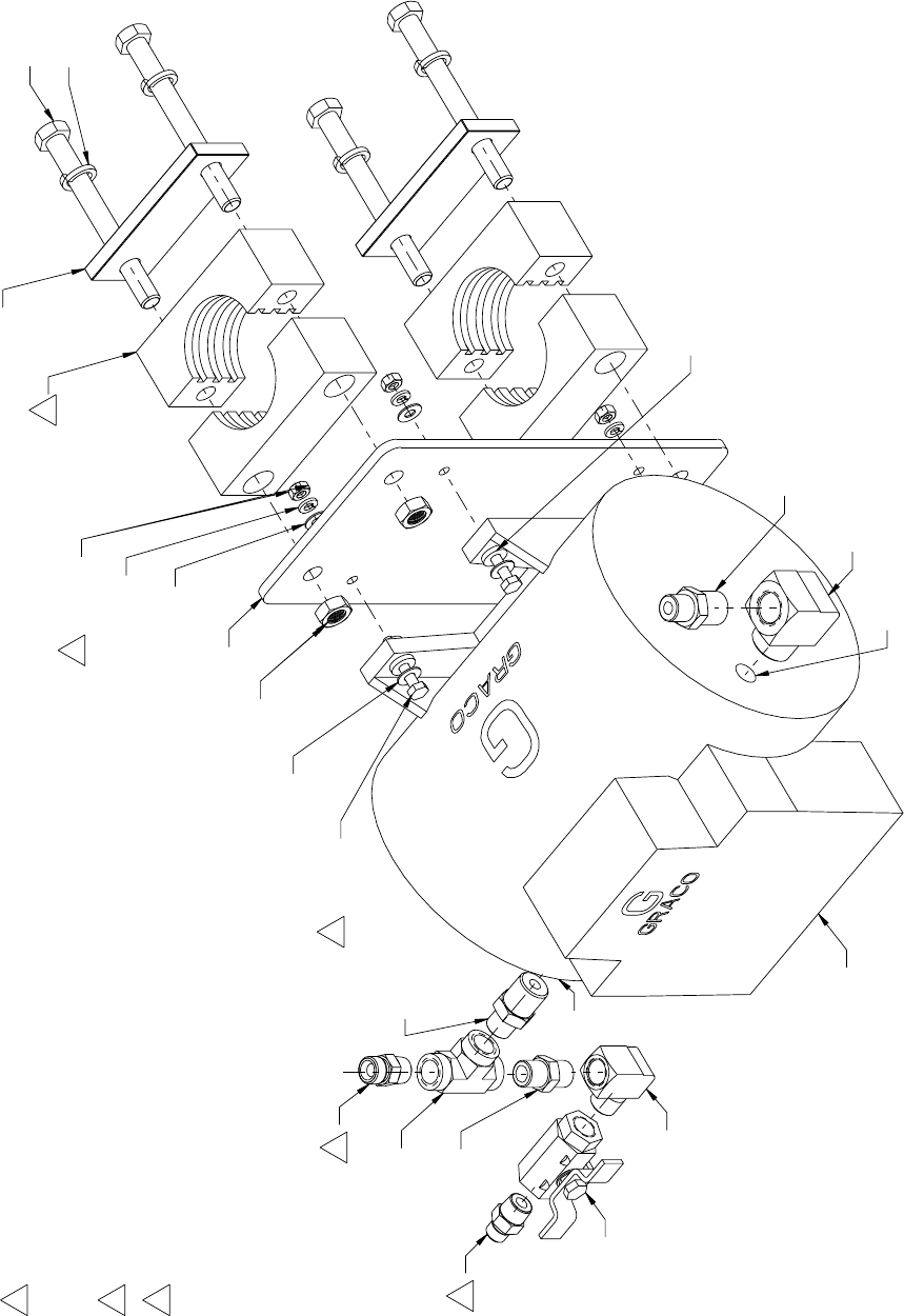
6XE$VVHPEO\'UDZLQJV
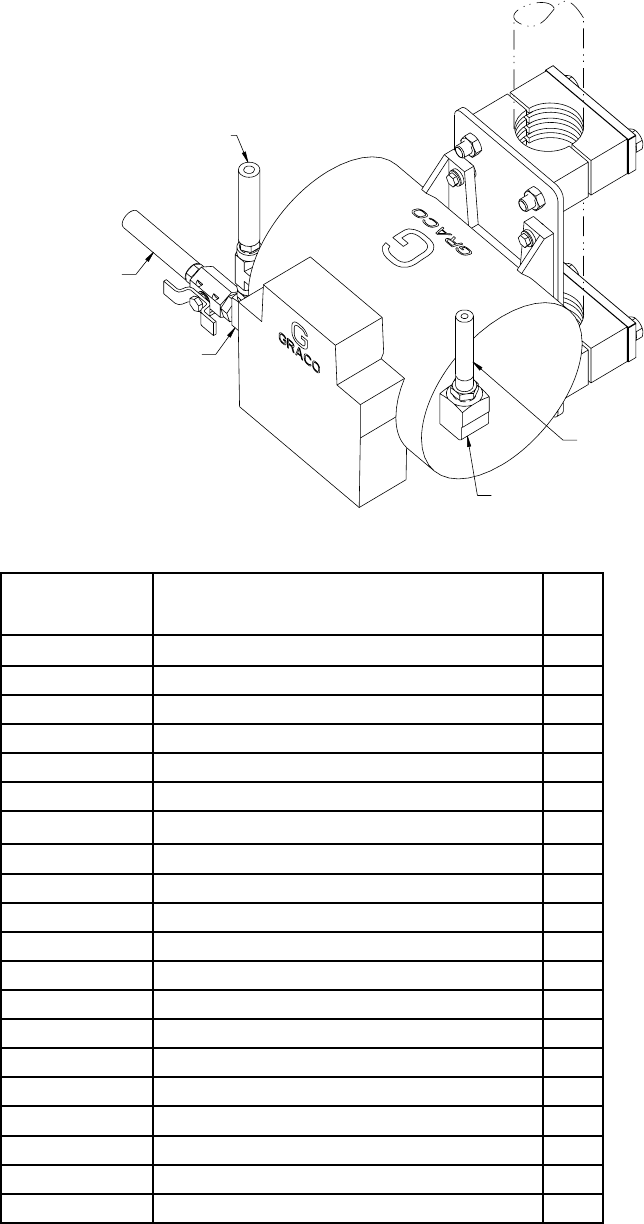
+HDWHU&RQYHUVLRQ.LW$VVHPEO\
5
2
1
1
1
2
96/0071/99
4 REQ'D
INLET
OUTLET
96/0058/99
4 REQ'D
5
8155-160C
4 REQ'D
96/0041/99
4 REQ'D
96/0037/99
4 REQ'D
96/0017/99
4 REQ'D
5
96/0041/99
4 REQ'D
(HEAT INSULATOR,167002)
(SUPPLIED WITH HEATER)
(SEE MANUAL 307363
FOR MTG INSTRUCTION)
TORQUE TO 35 IN-LB.
4. INCLUDE HEATER OPERATOR'S MANUAL IN KIT.
3. VIEW "B" SHOWS CORRECT ORIENTATION OF FITTINGS.
DRILL OUT THRU HOLES TO 33/64" AS REQUIRED.
UNATTACHED ITEMS INCLUDE: 14626-00, QTY 1 AND
14626-01, QTY 1
NOTES: UNLESS OTHERWISE SPECIFIED
226819
GCC470
20027-00
8462-15
14626-01
(2 TOTAL REQ'D)
21192-00
4342-23
8462-17
RM-850-02
14626-00
(2 TOTAL REQ'D)
8462-15
(2 TOTAL REQ'D)
7734-10
4 REQ'D
2X 19892-00
2X 19891-00
28 GC-1412D
Part
1XPEHU Description Qty
D-156-04 HOSE, ASSY 1
RM-850-02 FITTING, PIPE, TEE, 3/8 1
14626-00 FITTING, 3/8NPT X 3/8 NPS 2
14626-01 FITTING, 3/8NPT X 1/4 NPSM 2
19891-00 CLAMP, PIPE, SET 2
19892-00 PLATE, COVER, CLAMP 2
20027-00 FITTING, ELBOW, 1/2NPTM X 1/2NPTF CP 1
226819 HEATER, VISCON (240 VOLT) 1
21192-00 VALVE, BALL, 2-WAY, 3/8 1
GCC470 PLATE, HEATER, MOUNTING 1
96/0017/99 NUT, HEX, 1/4-20, MS, GR2 4
4342-23 FITTING, ELBOW, 3/8 NPTM X 3/8 NPTF 1
7734-10 WASHER, LOCK, SPRING, 1/2 4
8155-160C SCREW, HXHD, CS, .500-13X5.000ZP 4
8462-15 FITTING, PIPE, NIPPLE, HEX, 1/2 X 3/8 NPT 2
8462-17 FITTING, PIPE, NIPPLE, HEX, 3/8 X 3/8 NPT 1
96/0071/99 NUT, HEX, 1/2-13, MS, GR2 4
96/0037/99 WASHER, LOCK, SPLIT, 1/4, MS 4
96/0041/99 WASHER, FLAT, 1/4, 0.28 X 0.63 X 0.065 8
96/0058/99 SCREW, HHC, 1/4-20 X 1.50, MS, GR5 4
6XE$VVHPEO\'UDZLQJV
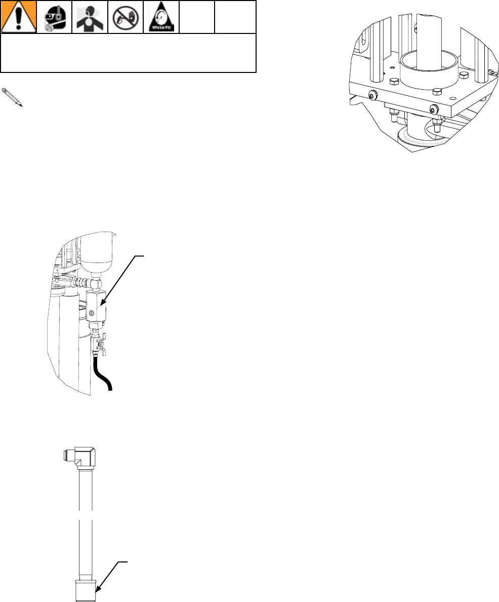
+HDWHU&RQYHUVLRQ.LW$VVHPEO\
(20260-00, PART OF TANK ASSY)
BACK TO TANK
INLET
OUTLET
(20195-25, PART OF HOSE ASSY)
TO GUN
D-156-04
FROM PUMP
(MAY BE SHIPPED
DISASSEMBLED)
GC-1412D 29
Maintenance Maintenance
See Indy and Formula gun manuals for daily maintenance
and parts replacement procedures.
1. &OHDQ ¿OWHU DW UHVLQ SXPS :KHQ RSHQLQJ SXPS UHOLHI
YDOYHPDNHVXUHDOOUHVLQDQGDLULVHYDFXDWHGIURPVXUJH
bottle.
2. ,QVSHFWDQGFOHDQ¿OWHURQSLFNXSZDQG
3. Clean pump lube cup and add fresh pump lube.
Fluid Filter Assembly
Filter
Before performing any maintenance on this Dispense
Gun - Follow pressure relief procedures on page 19.

30 GC-1412D
Technical Data
Category Data
0D[LPXP)OXLG:RUNLQJ3UHVVXUH 1300 psi (9 MPa, 90 bar)
0D[LPXP)OXLG:RUNLQJ3UHVVXUH 1700 psi (12 MPa, 117 bar)
0D[LPXP)OXLG:RUNLQJ3UHVVXUH 2000 psi (14 MPa, 138 bar)
Maximum Air Inlet Pressure 100 psi (0.7 MPa, 7 bar)
Typical Flow Rate of Pattern Guns Refer to gun manual
Maximum Fluid Temperature 100° F (38° C)
A Component (Catalyst) Inlet Size 1/4 in. Tube
B Component (Resin) Inlet Size 1 5/16-12 UN-2A Male
Sound Pressure (20864-05) 84.83 dB(A)
Sound Pressure (21780-01) 85.47 dB(A)
Sound Pressure (22026-01) 84.83 dB(A)
Sound Power, measured per ISO 9614-2 (20864-05) 87.04 dB(A)
Sound Power, measured per ISO 9614-2 (21780-01) 91.66 dB(A)
Sound Power, measured per ISO 9614-2 (22026-01) 87.04 dB(A)
Dimensions 88 L X 32 W X 18 H ( 2235.2 X 812.8 X 457.2 mm)
Weight /EVNJ
Wetted Parts
Catalyst- Chemically coated aluminum, stainless steel,
chemically resistant o-rings.
Resin- Carbon steel, carbide, chemically resistant o-
rings.

GC-1412D 31
Notes
Graco Ohio Standard Warranty
Graco warrants all equipment referenced in this document which is manufactured by Graco and bearing its name to be free from
GHIHFWVLQPDWHULDODQGZRUNPDQVKLSRQWKHGDWHRIVDOHWRWKHRULJLQDOSXUFKDVHUIRUXVH:LWKWKHH[FHSWLRQRIDQ\VSHFLDO
extended, or limited warranty published by Graco, Graco will, for a period of twelve months from the date of sale, repair or replace
any part of the equipment determined by Graco to be defective. This warranty applies only when the equipment is installed, operated
and maintained in accordance with Graco’s written recommendations.
This warranty does not cover, and Graco shall not be liable for general wear and tear, or any malfunction, damage or wear caused
by faulty installation, misapplication, abrasion, corrosion, inadequate or improper maintenance, negligence, accident, tampering,
or substitution of non-Graco component parts. Nor shall Graco be liable for malfunction, damage or wear caused by the incompat-
ibility of Graco equipment with structures, accessories, equipment or materials not supplied by Graco, or the improper design,
manufacture, installation, operation or maintenance of structures, accessories, equipment or materials not supplied by Graco.
This warranty is conditioned upon the prepaid return of the equipment claimed to be defective to an authorized Graco distributor
IRUYHUL¿FDWLRQRIWKHFODLPHGGHIHFW,IWKHFODLPHGGHIHFWLVYHUL¿HG*UDFRZLOOUHSDLURUUHSODFHIUHHRIFKDUJHDQ\GHIHFWLYHSDUWV
The equipment will be returned to the original purchaser transportation prepaid. If inspection of the equipment does not disclose
DQ\GHIHFWLQPDWHULDORUZRUNPDQVKLSUHSDLUVZLOOEHPDGHDWDUHDVRQDEOHFKDUJHZKLFKFKDUJHVPD\LQFOXGHWKHFRVWVRI
parts, labor, and transportation.
THIS WARRANTY IS EXCLUSIVE, AND IS IN LIEU OF ANY OTHER WARRANTIES, EXPRESS OR IMPLIED, INCLUDING BUT NOT LIMITED
TO WARRANTY OF MERCHANTABILITY OR WARRANTY OF FITNESS FOR A PARTICULAR PURPOSE.
Graco’s sole obligation and buyer’s sole remedy for any breach of warranty shall be as set forth above. The buyer agrees that no other remedy
LQFOXGLQJEXWQRWOLPLWHGWRLQFLGHQWDORUFRQVHTXHQWLDOGDPDJHVIRUORVWSUR¿WVORVWVDOHVLQMXU\WRSHUVRQRUSURSHUW\RUDQ\RWKHULQFLGHQWDO
or consequential loss) shall be available. Any action for breach of warranty must be brought within two (2) years of the date of sale.
GRACO MAKES NO WARRANTY, AND DISCLAIMS ALL IMPLIED WARRANTIES OF MERCHANTABILITY AND FITNESS FOR A PARTICULAR
PURPOSE, IN CONNECTION WITH ACCESSORIES, EQUIPMENT, MATERIALS OR COMPONENTS SOLD BUT NOT MANUFACTURED
BY GRACO. These items sold, but not manufactured by Graco (such as electric motors, switches, hose, etc.), are subject to the warranty, if any, of
WKHLUPDQXIDFWXUHU*UDFRZLOOSURYLGHSXUFKDVHUZLWKUHDVRQDEOHDVVLVWDQFHLQPDNLQJDQ\FODLPIRUEUHDFKRIWKHVHZDUUDQWLHV,QQRHYHQWZLOO
Graco be liable for indirect, incidental, special or consequential damages resulting from Graco supplying equipment hereunder, or the furnishing,
performance, or use of any products or other goods sold hereto, whether due to a breach of contract, breach of warranty, the negligence of Graco,
or otherwise.
FOR GRACO CANADA CUSTOMERS
7KH3DUWLHVDFNQRZOHGJHWKDWWKH\KDYHUHTXLUHGWKDWWKHSUHVHQWGRFXPHQWDVZHOODVDOOGRFXPHQWVQRWLFHVDQGOHJDOSURFHHGLQJVHQWHUHGLQWR
given or instituted pursuant hereto or relating directly or indirectly hereto, be drawn up in English. Les parties reconnaissent avoir convenu que
la rédaction du présente document sera en Anglais, ainsi que tous documents, avis et procédures judiciaires exécutés, donnés ou intentés, à la
suite de ou en rapport, directement ou indirectement, avec les procédures concernées.
Graco Ohio Information
TO PLACE AN ORDER, contact your Graco distributor or call to identify the nearest distributor.
Phone: 1-800-746-1334 or Fax: 1-330-966-3006
$OOZULWWHQDQGYLVXDOGDWDFRQWDLQHGLQWKLVGRFXPHQWUHÀHFWVWKHODWHVWSURGXFWLQIRUPDWLRQDYDLODEOHDWWKHWLPHRI
publication. Graco reserves the right to make changes at any time without notice.
This manual contains English. GC-1412
Graco Headquarters: Minneapolis
,QWHUQDWLRQDO2I¿FHVBelgium, China, Japan, Korea
GRACO OHIO INC. 8400 PORT JACKSON AVE NW, NORTH CANTON, OH 44720
Copyright 2008, Graco Ohio Inc. is registered to ISO 9001
www.graco.com
Revised 03/2009
