Graco 312497G Trabon Divider Valves, Instructions English User Manual To The 84f868eb 7033 4c25 9bc3 5514bca85759
User Manual: Graco 312497G to the manual
Open the PDF directly: View PDF ![]() .
.
Page Count: 44
Instructions
For series progressive, oil and grease lubrication. For Professional Use Only.
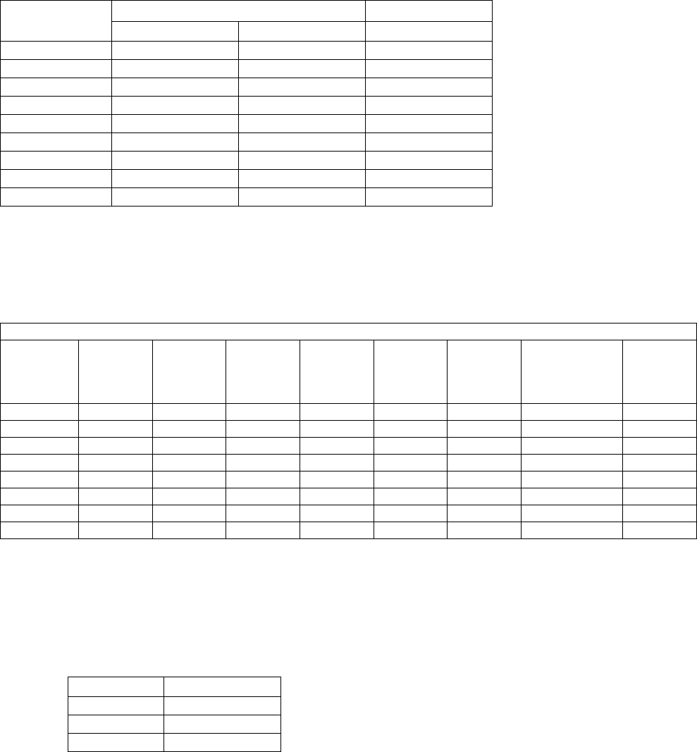
Models/Maximum Pressure
Table 1: Maximum Pressure Lube Points Table 2: MGO Series-Flo Divider Maximum
Operating Pressures
Important Safety Instructions
Read all warnings and instructions in this
manual. Keep these instructions.
Divider Type
Maximum
Operating
Pressure kPSI
(MPa, bar)
Maximum
Sections
MD 3.0 (20.7, 207) 2
MJ/MJSS 2.0 (13.8, 138) 8
MSP 3.5 (24.1, 241) 8
MHH 7.5 (51.7, 517) 8
MX 3.0 (20.7, 207) 10
MXP 3.0 (20.7, 207) 10
MGO See Table 2 11
Maximum Operating
Pressure kPSI (MPa, bar) Number of Sections
6.0 (41.4, 414) 3 to 7
5.5 (37.9, 379) 8
4.0 (27.6, 276) 9
4.5 (31.0, 310) 10
4.0 (27.6, 276) 11
312497G
EN
Trabon
Divider Valves
Warnings
2312497G
Warnings
The following Warnings are for the setup, use, grounding, maintenance and repair of this equipment. The exclama-
tion point symbol alerts you to a general warning and hazard symbols refer to procedure-specific risks. Refer back to
these Warnings. Additional, product-specific warnings may be found throughout the body of this manual where appli-
cable.
Pressure Relief Procedure
Follow this Pressure Relief Procedure whenever you
are instructed to relieve pressure or check or service
equipment.
1. Verify pump feeding valve is stopped and discon-
nected from, or locked out of it’s driver.
2. Using a wrench, slowly loosen inlet nut.
3. Then, using a wrench, slowly loosen each port nut.
WARNING
EQUIPMENT MISUSE HAZARD
Misuse can cause death or serious injury.
• Do not operate the unit when fatigued or under the influence of drugs or alcohol.
• Do not exceed the maximum working pressure or temperature rating of the lowest rated system
component. See Technical Data in all equipment manuals.
• Use fluids and solvents that are compatible with equipment wetted parts. See Technical Data in all
equipment manuals. Read fluid and solvent manufacturer’s warnings. For complete information about
your material, request MSDS forms from distributor or retailer.
• Check equipment daily. Repair or replace worn or damaged parts immediately with genuine
manufacturer’s replacement parts only.
• Do not alter or modify equipment.
• Use equipment only for its intended purpose. Call your distributor for information.
• Keep children and animals away from work area.
• Comply with all applicable safety regulations.
SKIN INJECTION HAZARD
High-pressure fluid from dispense valve, hose leaks, or ruptured components will pierce skin. This may
look like just a cut, but it is a serious injury that can result in amputation. Get immediate surgical
treatment.
• Do not point dispense valve at anyone or at any part of the body.
• Do not put your hand over the end of the dispense nozzle.
• Do not stop or deflect leaks with your hand, body, glove, or rag.
• Follow Pressure Relief Procedure in this manual, when you stop spraying and before cleaning,
checking, or servicing equipment.
Setup
312497G 3
Setup
The divider valve is shipped ready to install in your sys-
tem. It has been factory-tested and should not require
any additional modification.
To install the divider valve in your system:
1. Determine an appropriate, remote mounting loca-
tion.
2. Install a rupture to atmosphere fitting with a blow-out
disk that is rated for 7,500 psi or less between the
force feed lubricator pump and master divider valve
inlet.
3. Install an analog pressure gauge at the inlet to the
divider valve.
4. Install a slow or no cycle shutdown in one of the pis-
ton enclosure plugs. Program it to shut down after
no more than 180 seconds without a complete
cycle.
5. Torque. See Table 4 on page 15.
As long as lubricant is supplied under pressure to the
inlet section of the divider assembly, valves sections will
continue to operate in a progressive manner. Divider
assemblies always follow a constant discharge pattern.
Whenever lubricant flow ceases, the valving pistons will
stop. When flow resumes, it will start again at the same
point in the discharge cycle.
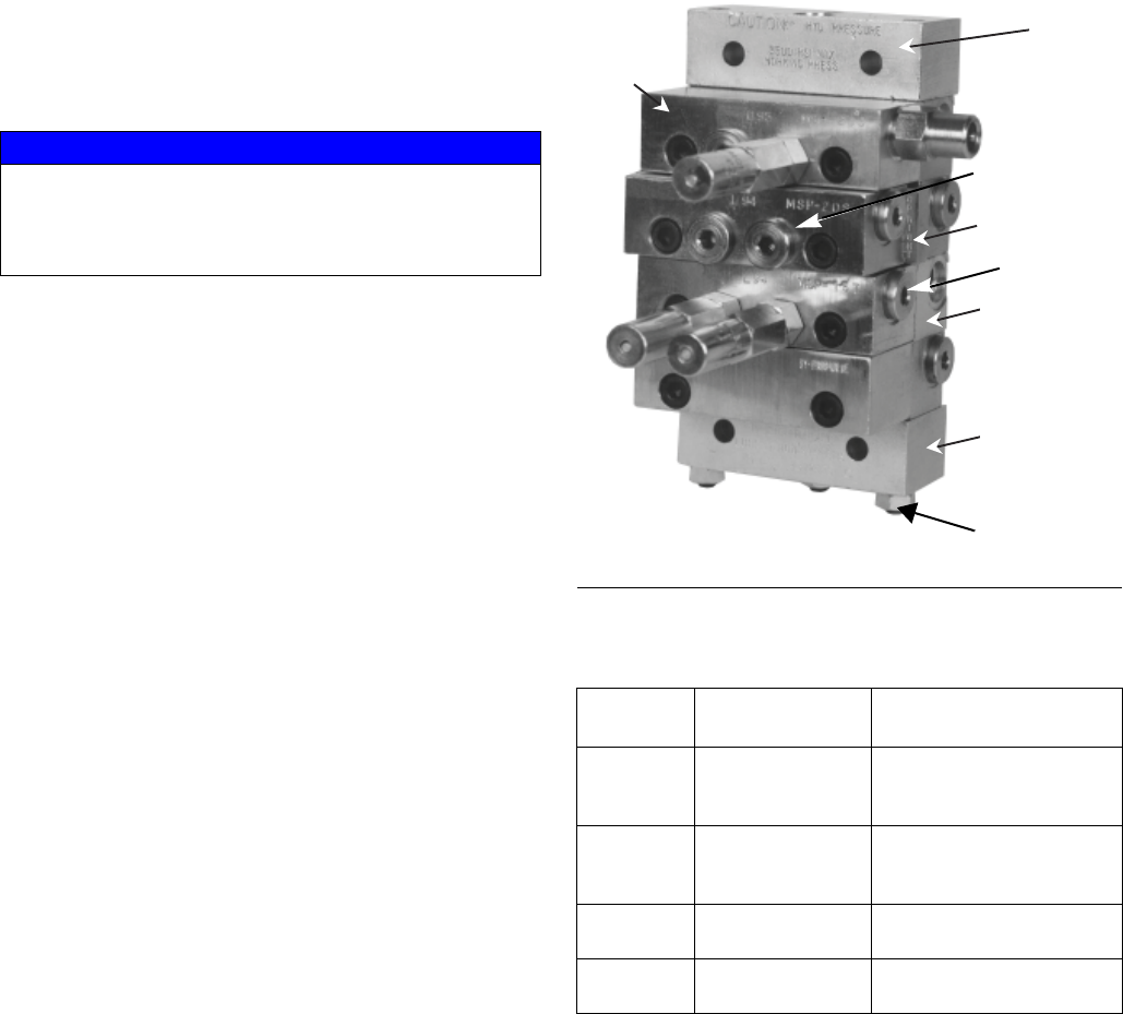
Component Identification
Table 3: Typical Divider Valve
Combinations
Divider Valves
A Series-Flo type divider valve is a manifold proportion-
ing device consisting of an inlet and end section plus a
minimum of three valve sections. The divider valve is
manifolded together with tie rods and nuts. A master
divider valve is the first divider valve downstream from
the lube pump. A secondary divider valve is any divider
valve receiving lubricant from the master divider valve.
NOTICE
Do not install a divider valve into a system rated for
more than the valve’s maximum operating pressure.
This type of installation could result in o-ring damage
and cause the divider valve to leak.
FIG. 1
MASTER SECONDARY
TYPE OF
APPLICATION
MJ MD Machine tools, Printing,
Wire Forging &
Packaging Machinery
MSP MJ, MSP Machine tools, Textile,
Glass & Can Machinery,
Mobile Equipment
MX, MXP MX, MXP, MSP Cranes, Presses, Steel
Mills, etc.
MGO MX Levellers, Shears,
Conveyors, etc.
Inlet
Section
Valve
Section
Crossport
Plate
Subplates with
Output Ports
End
Section
TI11117
Indicator/ Port Plug
End Plug
Tie Rod Nut
Setup
4312497G
Valve Sections (MSP, MHH and MXP
modular-type, divider valves, only)
Valve sections (three or more required per manifold)
contain a piston specially fitted to that section, built in
outlet check valves and various passageways that,
working with the piston, meters and valves the flow of
lubricant (FIG. 2).
Valve sections may be manufactured to require one or
two lube outlets. Stamping located on the face of each
section indicates:
• the style of divider valve section, i.e., MSP, MX,
etc.,
• the discharge per piston stroke expressed in
thousandths of cubic inches (35 = .035 in3 )
and,
• the number of lube outlets required (S = single,
one outlet only; T = twin, two lube outlets
required).
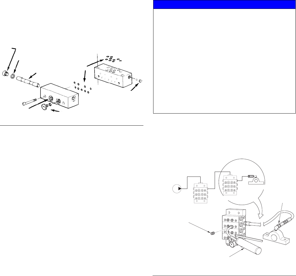
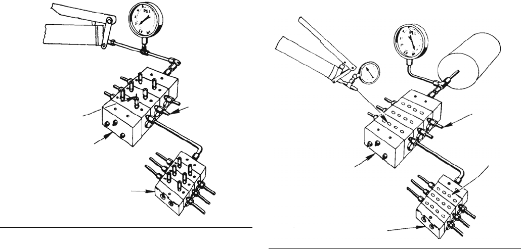
Prefilling Lubricant Distributor Lines
Follow the following procedure exactly as written, in the
order written.
Filling Secondary-to-Lube Point Lines
Refer to FIG. 3. when performing this procedure
.
1. Remove port plugs or performance indicators from
all of the indicator ports on front of secondary
divider valves.
2. Connect a hand pump filled with clean, filtered lubri-
cant to the indicator port closest to the first line to be
filled that corresponds to the output port that is feed-
ing the line to be filled.
FIG. 2
TI11102
Piston
Enclosure/End
Enclosure Plug Gasket
Piston
Indicator
Indicator Port Plug
Port
O-Rings
Check
Valve
Plug
NOTICE
• The initial startup and operation is the most critical
operating period for a newly installed machine in
terms of potential for being damaged by unre-
moved/unfiltered lubricant contaminants and lack of
adequate lubrication. Proper prefilling of lubrication
system ensures that lubricant is immediately avail-
able to every lube point during machine startup,
protecting them from damage.
• Use only clean oil filtered to the SAE -recom-
mended cleanliness level of ISO 18/14 (ISO Stan-
dard 4406) when prefilling a system. The
manufacturers of the machine tool and its compo-
nent bearings should be consulted to ensure that
the ISO 18/14 cleanliness level is adequate.
FIG. 3
TI11098
MASTER
HAND PUMP
BLEED HOSE
REMOVE INDICATOR
OR PORT PLUG
SECONDARY
LUBE POINT
HERE
Setup
312497G 5
3. In order to verify when lubricant is flowing and has
reached the end of the lube line, loosen the connec-
tor at the lube point of the line that is to be filled.
4. Stroke the hand pump until air-free lubricant is
observed flowing from the end of the lube line.
5. Tighten the lube line connector at the lube point, but
do not replace the port plugs or performance indica-
tors into the ports on the front of the working sec-
tion.
6. Repeat steps 1-5 for each of the other lube lines
connected to the other outlet ports in the secondary
divider valve assembly and for any other secondary
divider assemblies in the system.
NOTE: Do not replace any of the performance indicators
or port plugs removed in Step 1 until the line-filling pro-
cedure described in Section 2 (Filling Master -to-Sec-
ondary Lube Lines) has been completed.
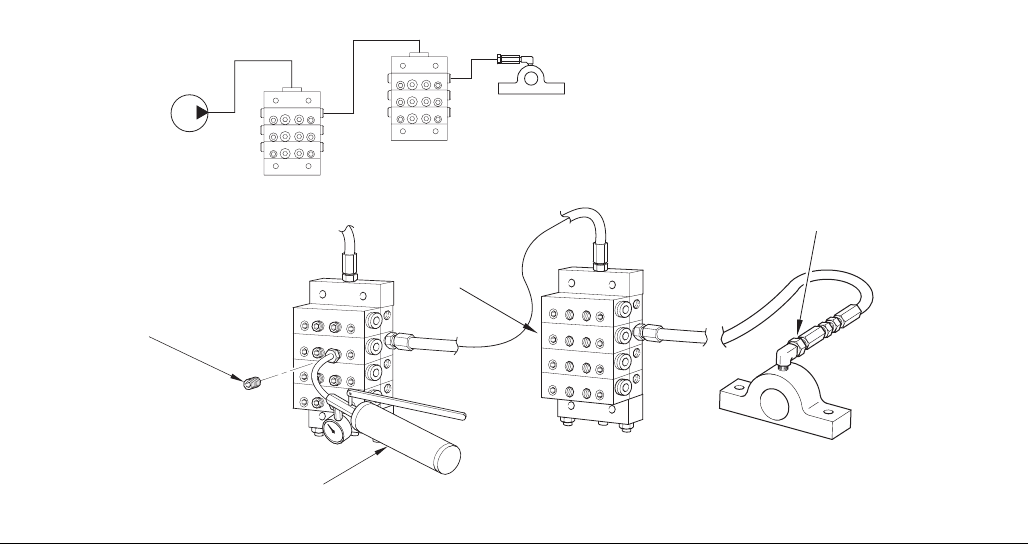
Filling Master-to-Secondary Lube Lines
Refer to FIG. 4. when performing this procedure.
1. Remove the port plugs or performance indicators
from all the indicator ports on the front of the master
divider valve.
2. Connect a hand pump filled with clean, filtered lubri-
cant to the indicator port closest to the lube output
port that is feeding the line to the secondary divider
valve.
3. Stroke the hand pump to fill the line between the
master divider valve and secondary divider valve.
4. Continue to stroke the pump until the lubricant
purges all the air out of the internal passages of the
secondary divider valve and lubricant flows freely
from all indicator ports with no evidence of included
air.
5. Reinstall the port plugs or performance indicators in
their respective positions in the secondary divider
valve. Do not replace the port plugs or performance
indicators in the master divider valve yet.
6. Repeat Steps 1-5 for each of the other lube lines
between the master divider valve and all other sec-
ondary divider valves.
NOTE: Do not replace any of the performance indicators
or port plugs removed in Step 1 from the master divider
valve assembly until the air-purging procedure
described in Section 3 (Filling Master Divider Valve) has
been completed.
FIG. 4
TI11099
MASTER
SECONDARY
LUBE POINT
REMOVE INDICATOR
OR PORT PLUG
HAND PUMP
BLEED
ALL PORTS
THROUGH
Setup
6312497G
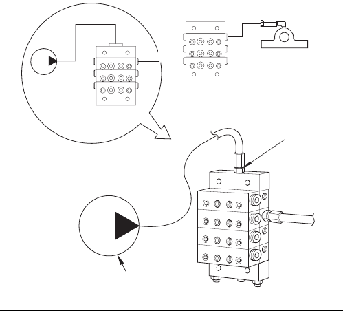
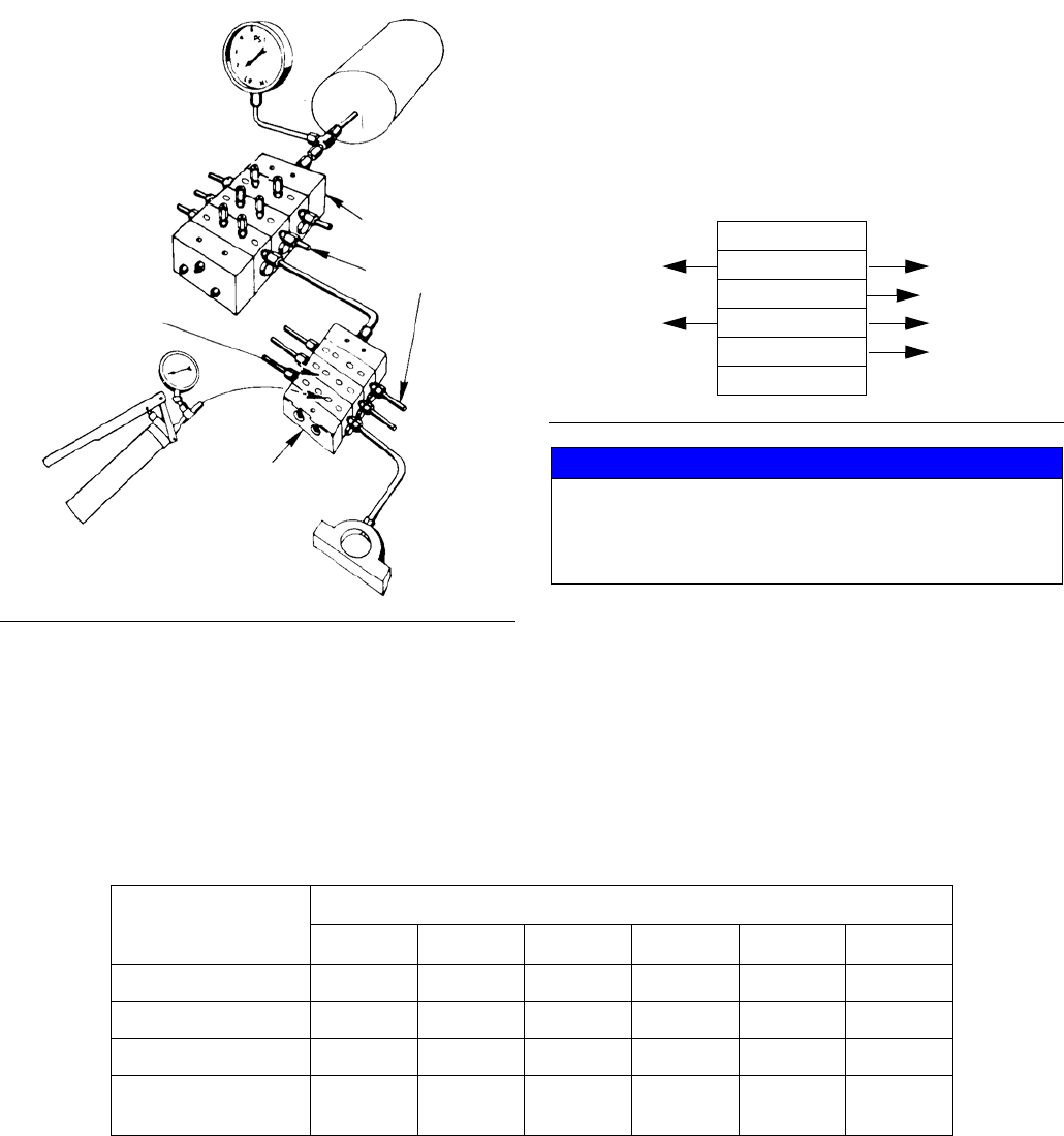
Filling Master Divider Valve
Refer to FIG. 5. when performing this procedure.
1. Verify that all port plugs or performance indicators
have been removed from all indicator ports in the
master divider valve.
2. Verify that the system pump is properly connected
to the inlet port of the master divider valve.
3. Cycle the system pump sufficiently to fill the main
feeder line between the pump and the master
divider valve and the lubricant is observed being
discharged from all of the indicator ports on the front
of the master divider valve with no evidence of
included air.
4. Reinstall the master divider valve port plugs or per-
formance indicators into their respective positions.
FIG. 5
TI11000
MASTER
BLEED
SECONDARY
LUBE POINT
HERE
CYCLE PUMP
Repair
312497G 7
Repair
General Repair Instructions
• Before performing any repair procedures, relieve
pressure, page 2.
• Pressure test distribution blocks yearly or every
8000 hours. Replace seals and divider valves as
necessary.
Purging Air From the System
Before machine operation is resumed following mainte-
nance or repair, manual system air purging must be per-
formed.
There are several air purging procedures available
depending upon the maintenance or repair procedure.
NOTE: Use only clean oil filtered to the SAE -recom-
mended cleanliness level of ISO 18/14 (ISO Standard
4406) when prefilling a system. The manufacturers of
the machine tool and its component bearings should be
consulted to ensure that the ISO 18/14 cleanliness level
is adequate.
Page Section Air purging after:
8 1 Replacing line between a secondary divider valve and lube point.
9 2 Replacing a line between the master divider valve and a secondary
divider valve.
10 3 Replacing a line between pump and master divider valve.
11 4 Adding or replacing any component in a master divider valve assembly.
12 5 Adding or replacing any component in module in a secondary divider
valve assembly.
Repair
8312497G
Section 1: Purging Air from Secondary Divider Valve Lube-to-Lube Point Lines
Steps 1-6, refer to FIG. 6.
1. Install the line from the secondary divider valve to
the lube point, but do not completely tighten the
connection at the lube point.
2. Remove the performance indicator port plug or the
performance indicator from the working valve sec-
tion on the secondary divider valve assembly corre-
sponding to the outlet port and the line connected to
the lube point.
3. Attach a hand pump filled with clean, filtered lubri-
cant to the port on the secondary divider valve that
was opened in Step 2.
4. Operate the hand pump until air-free lubricant is
observed flowing from the line at the lubrication
point.
5. Tighten the fitting at the lubrication point while lubri-
cant is still flowing.
6. Remove the hand pump and reinstall the perfor-
mance indicator or indicator port plug removed in
Step 2.
NOTE: If check valves were not installed at the lubrica-
tion point, lubricant may continually drain out of the line
when the secondary port is open. Therefore, when
check valves are not used, the method for bleeding this
line is to tighten the line at both ends and repeatedly
cycle the secondary divider valve via hand pump opera-
tion until lubricant, free of air, flows from the lubrication
point
FIG. 6
TI11098
MASTER
HAND PUMP
BLEED HOSE
REMOVE INDICATOR
OR PORT PLUG
SECONDARY
LUBE POINT
HERE
Repair
312497G 9
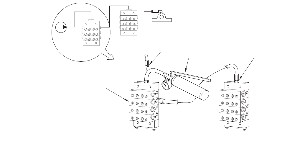
Section 2: Purging Air from Master to Secondary Divider Valve Lube Lines
Steps 1- 9, refer to FIG. 7.
1. Install the lines from the master divider valve to the
secondary divider valve, but do not completely
tighten the connection at the secondary divider
valve’s inlet.
2. Remove the performance indicator port plug or the
performance indicator from the working valve sec-
tion on the master divider valve assembly corre-
sponding to the outlet port and the line connected to
the secondary valve.
3. Attach a hand pump filled with clean, filtered lubri-
cant on the master divider valve that was opened in
Step 2.
4. Operate the hand pump until air-free lubricant is
observed flowing freely from the secondary valve’s
lube inlet connector.
5. Tighten the fitting at the secondary valve’s inlet
while lubricant is still flowing.
6. Remove all of the indicators or indicator port plugs
from the secondary divider valve’s working sections.
7. Operate the hand pump again until air-free lubricant
is observed flowing out of all the secondary divider
valve’s indicator ports.
8. Reinstall all of the performance indicators or port
plugs in the secondary divider valve while lubricant
is still flowing from the ports.
9. Remove the hand pump and reinstall the perfor-
mance indicator or indicator plug removed in Step 2
into the master divider working valve’s open port.
The system is now ready for operation.
FIG. 7
TI11113
MASTER
HAND PUMP
REMOVE INDICATOR
OR PORT PLUG
SECONDARY
LUBE POINT BLEED HERE
FIRST
AFTER BLEEDING INLET,
REMOVE ALL INDICATORS
OR PORT PLUGS AND BLEED
ALL PORTS
Repair
10 312497G
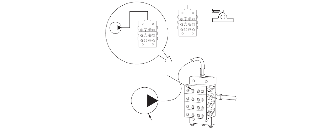
Section 3: Purging Air from Pump to Master Divider Valve Lines
Steps 1-3, refer to FIG. 8.
1. Install the line from the system pump to the master
divider valve, but do not completely tighten the con-
nection at the master valve’s lube inlet.
2. Cycle the system pump until air-free lubricant is
observed flowing from the line at the master divider
valve’s lube inlet.
3. Tighten the fitting at the lube inlet port while lubri-
cant is still flowing.
The system is now ready for operation.
FIG. 8
TI11114
BLEED THROUGH
SECONDARY
MASTER
ALL PORTS
SYSTEM PUMP
LUBE POINT
Repair
312497G 11
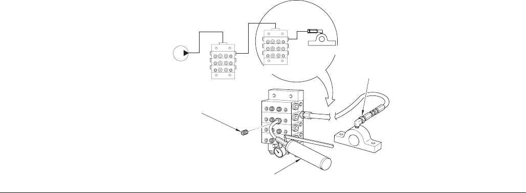
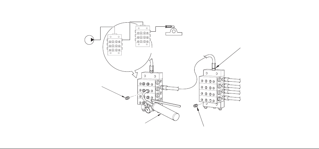
Section 4: Purging Air After Adding or Replacing a Master Divider Valve Module
Steps 1-7, refer to FIG. 9.
1. Install the new or replacement module into the mas-
ter divider valve assembly. Also connect the tubing
or hoses to the appropriate secondary divider
valve(s) or lubrication point(s) if the new/replace-
ment module is a base section.
2. Do not completely tighten the connection(s) at the
secondary divider valve’s inlet or at lubrication
points.
3. Disconnect and remove the line from the pump at
the inlet of the master divider valve.
4. Attach a hand pump filled with clean, filtered lubri-
cant to the inlet port on the master divider valve.
5. Operate the hand pump until air-free lubricant is
observed flowing from each secondary valve’s lube
inlet connector and/or each lubrication point’s con-
nector.
6. Tighten the fitting at the secondary valve inlet or at
the lubrication port while lubricant is still flowing.
7. Remove the hand pump and reconnect the system
pump to the inlet of the master divider valve.
The system is now ready for operation.
FIG. 9
TI11116
BLEED
SECONDARY
MASTER HAND PUMP
LUBE POINT
DISCONNECT
LINE
HERE
NEW VALVE
BLOCK
Repair
12 312497G
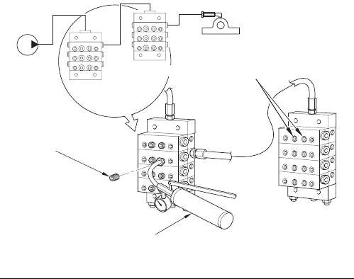
Section 5: Purging Air After Adding or Replacing a Secondary Divider Valve Module
Steps 1-8, refer to FIG. 10.
1. Install the new or replacement module to the sec-
ondary divider valve assembly. Also connect the
tubing or hoses to the appropriate lubrication point if
the new/replacement module is a base section.
2. Do not completely tighten the connection(s) at the
lubrication point.
3. Remove the performance indicator or indicator port
plug from the working valve section on the second-
ary divider valve assembly corresponding to the out-
let port and line connected to a particular lube point.
4. Attach a hand pump filled with clean, filtered lubri-
cant to the port on the secondary divider valve that
was opened in Step 3.
5. Operate the hand pump until air-free lubricant is
observed flowing from the loosened connector at
the lube point.
6. Tighten the fitting at the lube point while lubricant is
still flowing.
7. Repeat Steps 3 - 6 for any additional lubrication
points connected to the new module.
8. Remove the hand pump and reinstall the perfor-
mance indicator or port plug removed in Step 3 into
the secondary divider valve’s open port.
The system is now ready for operation.
FIG. 10
TI11115
MASTER
HAND PUMP
BLEED HOSE
REMOVE INDICATOR
OR PORT PLUG
SECONDARY
LUBE POINT
HERE
NEW VALVE
BLOCK
BLEED
HERE
Repair
312497G 13
Locating and Repairing
Blockages
Blocks will cause a higher than normal pumping pres-
sure. Depending on the application or system design,
this blockage will usually result in a complete loss of
lubricant flow into the total system and no bearing will be
receiving lubrication.
The loss of flow due to a blockage is first indicated with
the higher than normal system pressure that is devel-
oped by the pump as it attempts to overcome this block-
age. Higher pressure is limited, isolated and signaled
through the use of various performance indicators, reset
and relief, incorporated into the system design.
Performance Indicators
Performance indicators are pressure-sensitive devices
that pinpoint excessive pressure in the lubricating sys-
tem.
These devices are installed in the indicator ports of
divider valves, signal a fault either by causing an indica-
tor pin to protrude or by releasing lubricant into the
atmosphere.
NOTE: Never block a lube outlet that is designed to dis-
charge lubricant.
Reset Indicator with Memory
Reset indicators stop lube system operation when a
fault occurs. These devices can be used in either master
or secondary divider valves.
When a lube line becomes blocked, the resultant high
pressure pushes the indicator pin through the opening in
the cap. The high pressure prevents the affected divider
valve piston from completing its cycle, causing a pres-
sure backup through the divider valve which trips a pres-
sure switch upstream from the valve and shuts off the
pump.
The indicator pin remains extended until it is reset man-
ually. This helps locate the lube line that is blocked.
Rupture Indicator
Rupture indicators are used on MSP/MH divider valve
applications where lube system pressure exceed 2500
psi. The high pressure from the lube line blockage
causes a disc to rupture. The lubricant then forces an
indicator to protrude, locating the blockage. The high
pressure backs up through the system and trips a switch
to shut the system off. When the fault is corrected, the
disc must be replaced and the pin reset manually.
Automatic Relief Indicator
An automatic relief indicator pinpoints lube line blockage
but allows the lube system to continue supplying lubri-
cant to points that are not blocked. They are used pri-
marily in secondary divider valves. The excessive
pressure created by line blockage moves a piston,
enabling the lubricant to escape through a vent. When
the pressure is relieved, the spring resets the piston.
Because these devices permit the lube system to keep
operating when a lube point is blocked, a separate pres-
sure switch connected to an audible alarm should be
used to warn of high pressure.
Locating and Repairing Blockages
1. Make a visual inspection of the system. Check for
crushed lines or improper divider valve installation.
2. Verify that each divider valve outlet required to dis-
charge lubricant can do so and that no pipe plugs
have been installed in an outlet designed to serve a
bearing or another divider valve.
3. Use a manual pump with a gauge. Fill the pump with
clean, filtered lubricant. Connect the manual pump
to the inlet of the master divider valve and slowly
operate pump. If system will not cycle freely, below
1500 psi, see Master Divider Valve Equipped with
Performance Indicator [Step 4a (below)].
NOTE: Use only clean oil filtered to the SAE -recom-
mended cleanliness level of ISO 18/14 (ISO Standard
4406) when prefilling a system. The manufacturers of
the machine tool and its component bearings should be
consulted to ensure that the ISO 18/14 cleanliness level
is adequate.
Repair
14 312497G
4a. Master Divider Valve Equipped With Performance
Indicator
With manual pump connected to the master divider
valve as outlined in Locating Blockages, Step 3,
raise pressure to 2000 psi. The indicators in the
indicator ports will signal the location of the block-
age. An indicator in the up position indicates pres-
sure is in that outgoing line and signals the blockage
is in the area being served from this outlet (FIG. 11).
If no indicator pins are protruding, the blockage is in
the master divider valve.
4b. Master Divider Valve Equipped Without Performance
Indicator
1) With manual pump connected to the master
divider valve as outlined in Locating Blockages,
Step 3, raise pressure to 2000 psi.
2) Remove, one at a time, each indicator port plug
and attempt to operate manual pump after each
plug is removed. Do not exceed 2000 psi.
3) If pressure drops and the master cycles freely
after an indicator port plug is removed, then
blockage is downstream in the area that is being
served from that outlet. See Locating Block-
ages, Step 3.
NOTE:
• If all indicator port plugs are removed, the master
will not cycle. Blockage is in this divider valve.
• When indicator port plug of a blocked area is
removed, a small shot of trapped lubricant will usu-
ally surge out of this outlet as the inlet pressure on
the divider valve drops.
• If testing (Step 4) indicates a blockage in the master
divider valve, this divider valve must be disassem-
bled and cleaned. See Clean Divider Valve, Step 7,
page 15.
5. If in Step 4, a blockage has been indicated
downstream of the master divider valve, install a
manual pump in the indicator port of the master
divider valve that is common to the blocked area.
(See FIG. 12).
a. Proceed to downstream secondary divider valve
and remove all indicator port plugs.
b. Slowly operate manual pump. If lubricant can be
discharged freely through each of the indicator
ports of this divider valve, the blockage is not in
the supply line or the divider valve. Go to step 6.
If lubricant is not freely discharged through
open indicator ports of the second divider valve,
the blockage is in this divider valve or its supply
line. Disconnect supply line at secondary inlet
FIG. 11
HAND PUMP
LUBE
INDICATOR PIN UP
MASTER
SECONDARY
OUTLETS
DIVDER
VALVE
DIVIDER
VALVE
TI11103
FIG. 12
TI11104
HAND PUMP SYSTEM PUMP
MASTER
DIVDER
VALVE
SECONDARY
DIVIDER
VALVE
LUBE
OUTLETS
INDICATOR
PORT
PLUGS
REMOVED
Repair
312497G 15
fitting and slowly operate manual pump to verify
location. If blockage is in this divider valve, go to
step 7.
6. Install manual pump into each indicator port of sec-
ondary divider valve in turn and slowly operate
pump (FIG. 13). If high pressure exists, blockage
has been located. Look for crushed line, tight
bearing, improperly drilled fittings and/or lube
inlet port. Correct as necessary.
7. Clean Divider Valve
NOTE: Dirt and foreign material will damage lubricating
equipment. Perform all service and disassembly under
the cleanest possible conditions.
a. Before disassembling any divider valve, make a
sketch noting the arrangement of Valve Sec-
tions. For example: INLET 10T - 20S - 10T -
30S - END (FIG. 14). Also remove end plugs
only and try to move each piston back and forth
without removing the piston from the valve sec-
tion.
b. If all pistons move freely and there is no indica-
tion of a more serious problem, replace end
plugs.
c. Using a new gasket, tighten and torque as indi-
cated in Table 1 (page 11).
FIG. 13
HAND PUMP
SYSTEM PUMP
MASTER
DIVDER
VALVE
SECONDARY
DIVIDER
VALVE
LUBE
OUTLE
T
INDICATOR PORT
PLUGS REMOVED
BEARING
LUBE OUTLETS
FIG. 14
NOTICE
Do not insert hard metal objects into piston bore (i.e.,
punches, screwdrivers, etc.). Hard metal objects can
damage the surface and cause divider valves to leak
fluid. Use a brass rod and hand pressure only.
Inlet
10T
20S
10T
30S
End
Table 4: Torque Values (*see FIG. 1, page 3)
Assembly Torque (ft-lbs)
MJ MD MSP/MH MX MXP MGO
Tie Rod Nuts 12 5-8 23 6-9 12
Indicator Plugs* 6-7 15 8-9 18 12-15 6-8
End Plugs* 11-13 12-15 46 46-50 15
Valve Section
Mounting Screw
--8-9-12-13-
Repair
16 312497G
d. Clean sections and pistons in suitable clean sol-
vent until all lubricant has been removed.
e. Use compressed air to dry and blow out all
ports thoroughly.
A small metal probe should be used to make
sure all passages are clean and open.
Inspect cylinder bore and piston carefully for
scratches, score marks or other damage.
NOTE: If either piston or cylinder bore is damaged, a
new section must be installed. All pistons are selectively
fitted to the bore for proper clearance. Be sure to rein-
stall piston only into the valve section from which it was
removed.
f. If divider valve section and piston both appear in
good condition, reassemble section making cer-
tain piston slides smoothly but snugly in cylinder
bore.
g. Repeat cleaning and inspection of each section.
After all sections have been cleaned, blown out,
inspected and found to be in good condition,
reassemble divider valve using notes and
sketches (Step 7) as a reference.
NOTE:
• Always use new gaskets.
• Test operation of divider valve using manual pump.
Contamination Blockage
If dirt, foreign material or any other form of contamina-
tion is found in a divider valve, cleaning that divider valve
will only temporarily solve contamination blockage prob-
lems. The source of the contamination must be elimi-
nated for satisfactory service.
The system filtering method must be investigated, filter
elements should be inspected and cleaned if necessary.
The reservoir filling method should be reviewed to elimi-
nate any chance of foreign material entering the reser-
voir during filling.
Separation Blockage
If a hard wax or soap-like material is found in the Valve
Section, grease separation is occurring. This means that
the oil is being squeezed from the grease at normal sys-
tem operating pressure and the grease thickener is
being deposited in the divider valve. Cleaning the divider
valve will only temporarily solve the problem. Consult
your lubricant supplier for recommendations on alter-
nate lubricants and your local Graco/Trabon distributor
to verify compatibility with centralized lubricating sys-
tems.
If all indictor port plugs are removed, master will not
cycle. Blockage is in this divider valve.(FIG. 11).
MD Series
312497G 17
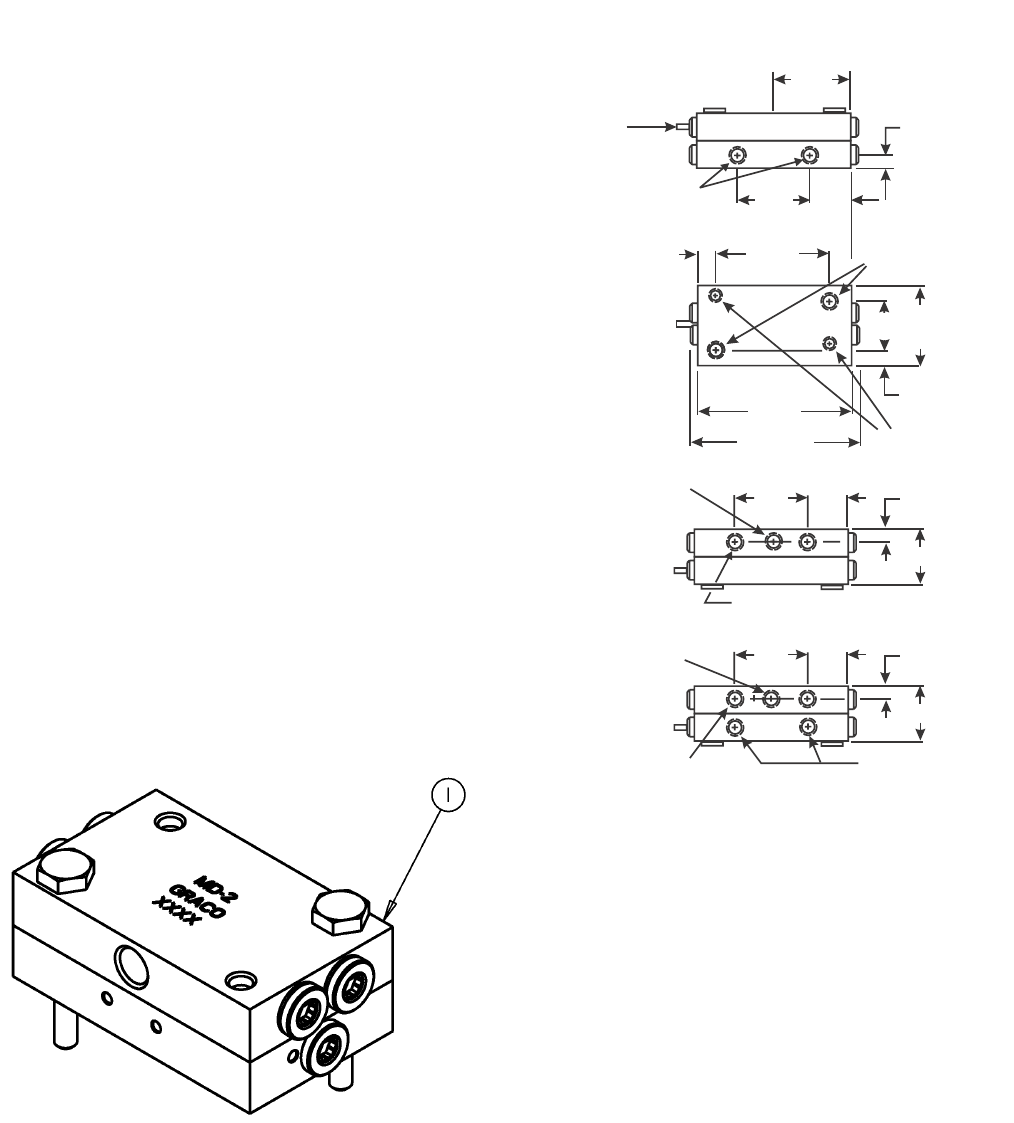
MD Series
Technical Data
Parts
Dimensions
Material Steel
Pressure (max) 3,000 psi (207 bar)
Lubricant Oil or grease
Net Weight (approx.) 1-lb. 8 oz (0.68 kg)
Volume (Lubricant to cycle
divider valve one complete
cycle)
MD-2, MD-3, MD-4 0.080 in.3 (1.31 ccm)
MD-6 0.060 in.3 (0.98 ccm)
Torque Ratings
Assembly Bolts 8-9 ft. lbs
Enclosure Plugs 11-13 ft. lbs
Indicator Plug 15 ft. lbs
Outlet Plugs 6-7 ft. lbs.
Ref Part No. Description
1 562656 VALVE, feeder, MD 2
562657 VALVE, feeder, MD 3
562658 VALVE, feeder, MD 4
562659 VALVE, feeder, MD 6
562653 VALVE, feeder, MD 2, IND
562654 VALVE, feeder, MD 3, IND
562655 VALVE, feeder, MD 4, IND
563270 VALVE, feeder, MD 2, IND/Switch
563271 VALVE, feeder, MD 3, IND/Switch
564356 VALVE, feeder, MD 4, IND/Switch
1.19
(30.2
0.87
(22.0) 0.28
(7.11)
1.21
(30.9)
1.19
(30.2
0.87
(22.0) 0.28
(7.11)
1.21
(30.9)
1/8”OUTLET
LUBE INLET
1/8” OUTLET
3.12
(79.3)
3.00
(76.2)
Assembly
Bolts
0.25
(6.3)
1.25
(31.7)
1.75
(44.4)
2.12
(53.9)
0.40
(10.7)
0.28
(7.11) Dia. 2-Mtg. Holes
1.19
(30.2)
0.87
(22.0)
0.28
(7.11)
1.46
(37.0)
OUTLET
,5"%).,%4
v/54,%4-$/NLY
CYCLE INDICATOR
PIN (OPTIONAL)
ti11472
MJ Series
18 312497G
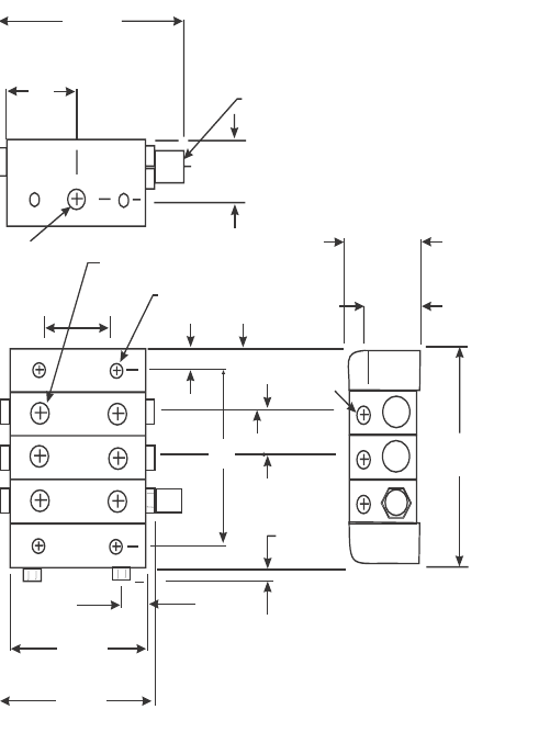
MJ Series
Technical Data Dimensions
Material Plated or Stainless Steel
Pressure (max) 2,000 psi (138 bar)
Lubricant Oil or grease up to NLGI
Grade 1
Max Operating Temperature 200°F (93°C)
Max Cycle Rate With
Cycle Pin
60 CPM
Net Weight (approx.)
3 section divider valve 1-lb. 15 oz (0.88 kg)
4 section divider valve 2 lbs. 5 oz (1.04 kg)
5 section divider valve 2 lbs. 11 oz (1.21 kg)
6 section divider valve 3 lbs. 1 oz (1.38 kg)
7 section divider valve 3 lbs. 7 oz (1.55 kg)
8 section divider valve 3 lbs. 13 oz (1.72 kg)
Torque Ratings
Tie Rod Nut 12 ft. lbs
Enclosure Plug 11-13 ft. lbs
Outlet Port Plugs 6-7 ft. lbs.
3.23
(82.2)
1.06
(26.9)
.750
(19.0)
CYCLE INDICATOR PIN (OPTIONAL)
L
UBE INLET INDICATOR OUTLET
.750
(19.0)
1.37
(34.9)
1.09
(27.7)
4 MTG. HOLES
.270 (6.8) .858
(21.79) LUBE
OUTLET
B
.250
(6.3)
.582 TYPICAL
(14.7)
2.54
(64.5)
2.12
(53.9)
.687
(17.4)
A
ti11474
MJ Series
312497G 19
Parts
Ref Part No. Description
1 562500 VALVE, assembly, MJ 5S
562501 VALVE, assembly, MJ 10S
562502 VALVE, assembly, MJ 15S
562503 VALVE, assembly, MJ 5T
562504 VALVE, assembly, MJ 10T
562505 VALVE, assembly, MJ 15T
562508 VALVE, assembly, IND MJ 10S
562512 VALVE, assembly, IND MJ 10S Left
562510 VALVE, assembly, IND MJ 10 T
562513 VALVE, assembly, IND MJ 10T Left
562509 VALVE, assembly, IND MJ 15S
562511 VALVE, assembly, IND MJ 15T
564205 VALVE, assembly, IND MJ 15T Left
562506 VALVE, assembly, SST MJ 5S SST
562507 VALVE, assembly, SST MJ 10S SST
564203 VALVE, assembly, SST MJ 5T SST
564204 VALVE, assembly, SST MJ 10T SST
2 560643 INLET, CRS, MJ
560644 INLET, SST, MJ
3 560645 END, CRS, MJ
561405 END, SST, MJ
4 557515 ROD, tie, MJ 3 (3 required)
557516 ROD, tie, MJ 4 (3 required)
557517 ROD, tie, MJ 5 (3 required)
557518 ROD, tie, MJ 6 (3 required)
557519 ROD, tie, MJ 7 (3 required)
557520 ROD, tie, MJ 8 (3 required)
560649 ROD, tie, MJ 9 (3 required)
558917 ROD, tie, MJ 3 SST(3 required)
124028 ROD, tie, MJ 4 SST(3 required)
124029 ROD, tie, MJ 5 SST (3 required)
124030 ROD, tie, MJ 6 SST (3 required)
124031 ROD, tie, MJ 7 SST (3 required)
124032 ROD, tie, MJ 8 SST (3 required)
124033 ROD, tie, MJ 9 SST (3 required)
5 556371 NUT, tie rod, 1/4-28 (3 required)
558633 NUT, tie rod, 1/4-28 SST (3 required)
MSP Series
20 312497G
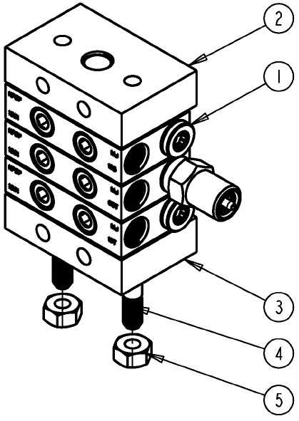
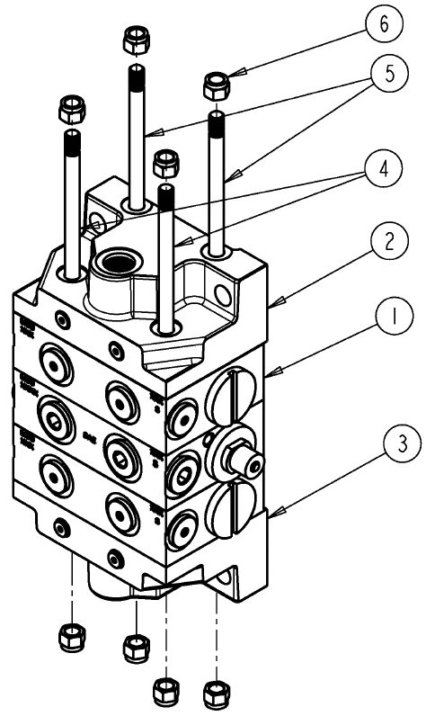
MSP Series
Technical Data
Material Corrosion Protected Steel (optional: Type 316 Stainless
Steel)
Pressure (max)
Zero Leak Inlet 1500 psi (104 bar)
Shunt/Shutoff Inlet 3000 psi (207 bar)
Ambient Temperature (max) 140°F (60°C)
Lubricant
Zero Leak Inlet Oil Only - up to 5000 SUS, requires 25 micron (min) filtra-
tion
Shunt/Shutoff Inlet Oil and fluid grease - filter oil through 25 micron filter and
grease through 100 micron mesh strainer
New Weight (approx.)
3 section divider valve assembly 5.9 lbs (2.7 kg)
4 section divider valve assembly 7.3 lbs (3.3 kg)
5 section divider valve assembly 8.7 lbs (4.0 kg)
6 section divider valve assembly 10.2 lbs (4.6 kg)
7 section divider valve assembly 11.6 lbs (5.6 kg)
8 section divider valve assembly 13.0 lbs (5.9 kg)
Torque Ratings
Mounting Screw 8-9 ft. lbs
Enclosure Plugs 6-8 ft. lbs
Indicator Port Plug 5-7 ft. lbs
Bleed Screws 1-2 ft. lbs.
Tie Rod Nut 5-8 ft. lbs.
MSP Series
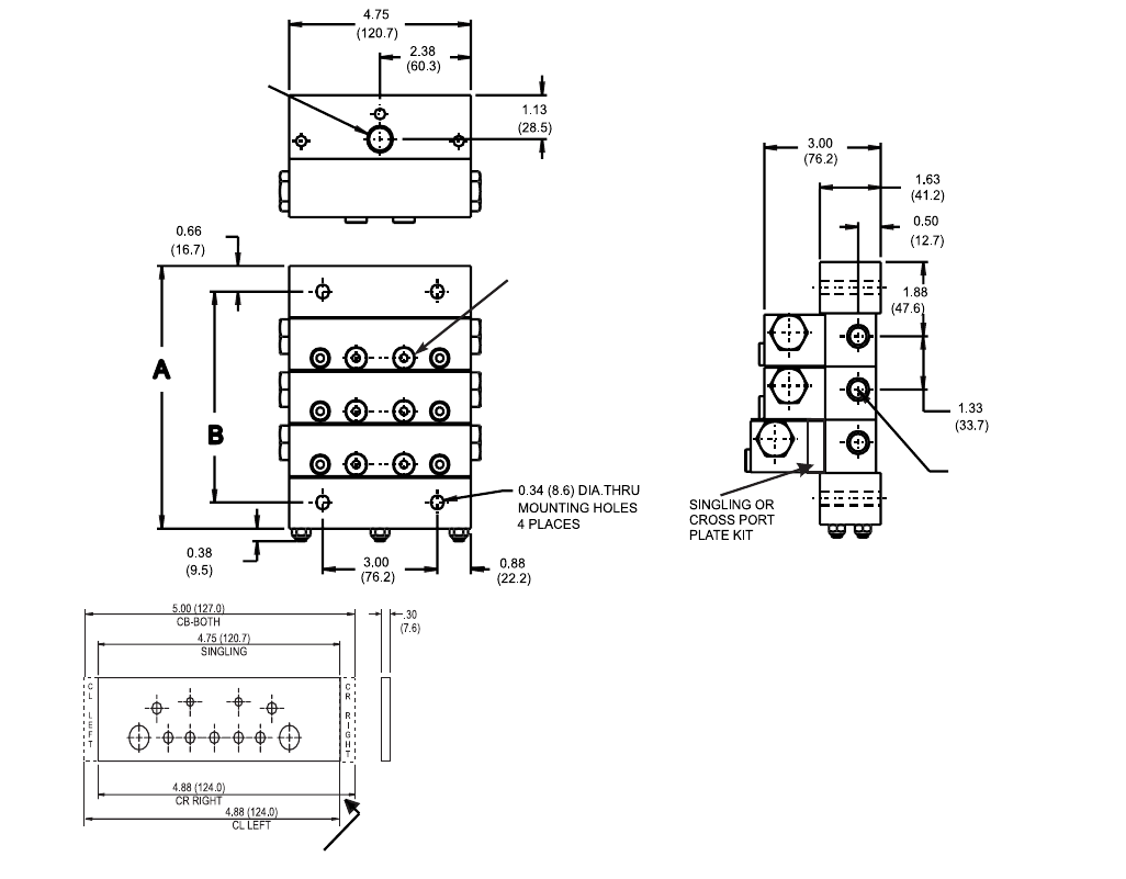
312497G 21
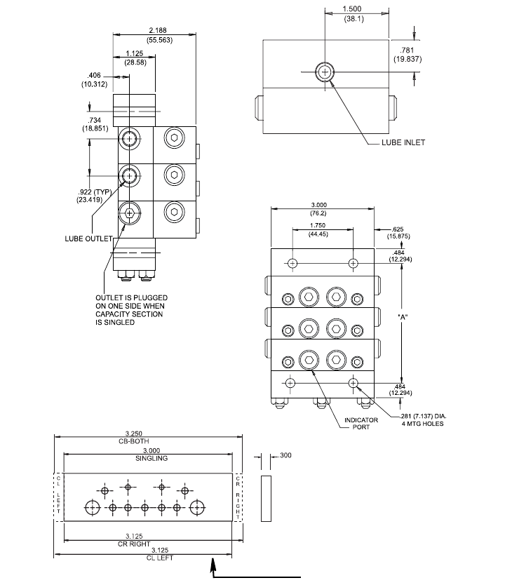
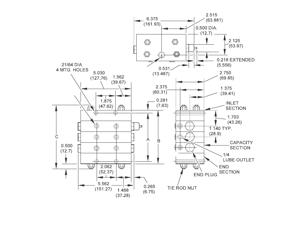
Dimensions
ti11478
CROSSPORT PLATE (OPTIONAL)
MSP Series
22 312497G
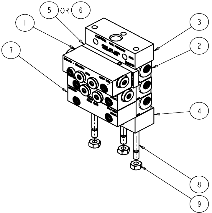
Parts
Ref Part No. Description
1 562711 VALVE, assembly MSP 05S
562712 VALVE, assembly MSP 10S
562713 VALVE, assembly MSP 15S
562714 VALVE, assembly MSP 20S
562715 VALVE, assembly MSP 25S
562716 VALVE, assembly MSP 30S
562717 VALVE, assembly MSP 35S
562718 VALVE, assembly MSP 40S
562720 VALVE, assembly MSP 05T
562721 VALVE, assembly MSP 10T
562722 VALVE, assembly MSP 15T
562723 VALVE, assembly MSP 20T
562724 VALVE, assembly MSP 25T
562725 VALVE, assembly MSP 30T
562726 VALVE, assembly MSP 35T
562727 VALVE, assembly MSP 40T
562729 VALVE, assembly IND MSP 20S
562730 VALVE, assembly IND MSP 25S
562731 VALVE, assembly IND MSP 30S
562732 VALVE, assembly IND MSP 35S
562733 VALVE, assembly IND MSP 40S
562734 VALVE, assembly IND left MSP 20S
562735 VALVE, assembly IND left MSP 25S
562736 VALVE, assembly IND left MSP 30S
562737 VALVE, assembly IND left MSP 35S
562738 VALVE, assembly IND left MSP 40S
562739 VALVE, assembly IND MSP 20T
562740 VALVE, assembly IND MSP 25T
562741 VALVE, assembly IND MSP 30T
562742 VALVE, assembly IND MSP 35T
562743 VALVE, assembly IND MSP 40T
562744 VALVE, assembly IND left MSP 20T
562745 VALVE, assembly IND left MSP 25T
562746 VALVE, assembly IND left MSP 30T
562747 VALVE, assembly IND left MSP 35T
562748 VALVE, assembly IND left MSP 40T
24B474 VALVE, single, 303 MSP .005
562755 VALVE, single, 303 MSP .010
24B475 VALVE, single, 303 MSP .015
562756 VALVE, single, 303 MSP .020
24B476 VALVE, single, 303 MSP .025
24B477 VALVE, single, 303 MSP .030
24B478 VALVE, single, 303 MSP .035
562757 VALVE, single, 303 MSP .040
24B479 VALVE, twin, 303 MSP .005
562758 VALVE, twin, 303 MSP .010
24B480 VALVE, twin, 303 MSP .015
562759 VALVE, twin, 303 MSP .020
24B481 VALVE, twin, 303 MSP .025
24B482 VALVE, twin, 303 MSP .030
24B483 VALVE, twin, 303 MSP .035
562760 VALVE, twin, 303 MSP .040
24B484 VALVE, single, 303 MSP .020 w/indicator
24B485 VALVE, single, 303 MSP .025 w/indicator
24B486 VALVE, single, 303 MSP .030 w/indicator
24B487 VALVE, single, 303 MSP .035 w/indicator
24B488 VALVE, single, 303 MSP .040 w/indicator
24B489 VALVE, twin, 303 MSP .020 w/indicator
24B490 VALVE, twin, 303 MSP .025 w/indicator
24B491 VALVE, twin, 303 MSP .030 w/indicator
24B492 VALVE, twin, 303 MSP .035 w/indicator
24B493 VALVE, twin, 303 MSP .040 w/indicator
2 24B497 BLOCK, base, 303 MSP
563425 BLOCK, base, MSP NPSF
563447 BLOCK, base, MSP, BSPP
563451 BLOCK, base, MSP, SAE
563479 BLOCK, base, MSP w/No outlets
3 560919 BLOCK, inlet, MSP, NPSF
560936 BLOCK, inlet, MSP, BSPP
560943 BLOCK, inlet, MSP, SAE
560976 BLOCK, inlet, MSP, ISO 6149
563421 BLOCK, inlet, MSP, NPSF, w/bleed
563422 BLOCK, inlet, MSP SAE w/bleed
4 563279 BLOCK, MSP end w/alt inlet
563424 BLOCK, end, MSP
5 563469 KIT, crossport bar, right
563470 KIT, crossport bar, left
563471 KIT, crossport bar, both
6 563472 KIT, singling bar
7 562660 VALVE, assembly bypass, standard MSP
8 557731 ROD, tie, 3 section, MSP (3 required)
557732 ROD, tie, 4 section, MSP (3 required)
557733 ROD, tie, 5 section, MSP (3 required)
557734 ROD, tie, 6 section, MSP (3 required)
557735 ROD, tie, 7 section, MSP (3 required)
557736 ROD, tie, 8 section, MSP (3 required)
557738 ROD, tie, 9 section, MSP (3 required)
557739 ROD, tie, 10 section, MSP (3 required)
557740 ROD, tie, 11 section, MSP (3 required)
9 556371 NUT, 1/4 - 28 (3 required)
Ref Part No. Description
MSP Series
312497G 23
MHH Series
24 312497G
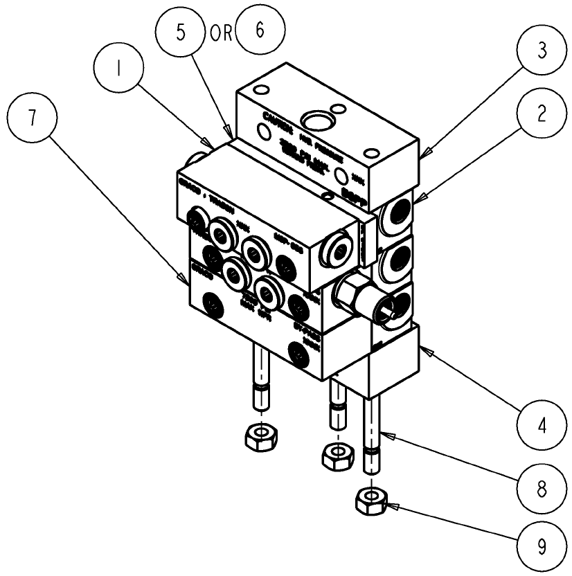
MHH Series
Technical Data
Material Steel Body (corrosion protected) Steel Piston (honed fit)
Pressure (max) 7,500 psi (517 bar) for Petroleum or Synthetic Oil - fluo-
roelastomer O-rings
Lubricant Petroleum or synthetic oil only
Maximum Operating Temperature
Fluoroelastomer O-rings (557722) 350°F (163°C)
Maximum Cycle Rate Without Cycle Pin 200 CPM
Net Weight (approx.)
3 section divider valve assembly 5.9 lbs (2.7 kg)
4 section divider valve assembly 7.3 lbs (3.3 kg)
5 section divider valve assembly 8.7 lbs (4.0 kg)
6 section divider valve assembly 10.2 lbs (4.6 kg)
7 section divider valve assembly 11.6 lbs (5.6 kg)
8 section divider valve assembly 13.0 lbs (5.9 kg)
Torque Ratings
Mounting Screw 8-9 ft. lbs
Enclosure Plugs 6-8 ft. lbs
Indicator Port Plug 5-7 ft. lbs
Bleed Screws 1-2 ft. lbs.
Tie Rod Nut 5-8 ft. lbs
MHH Series
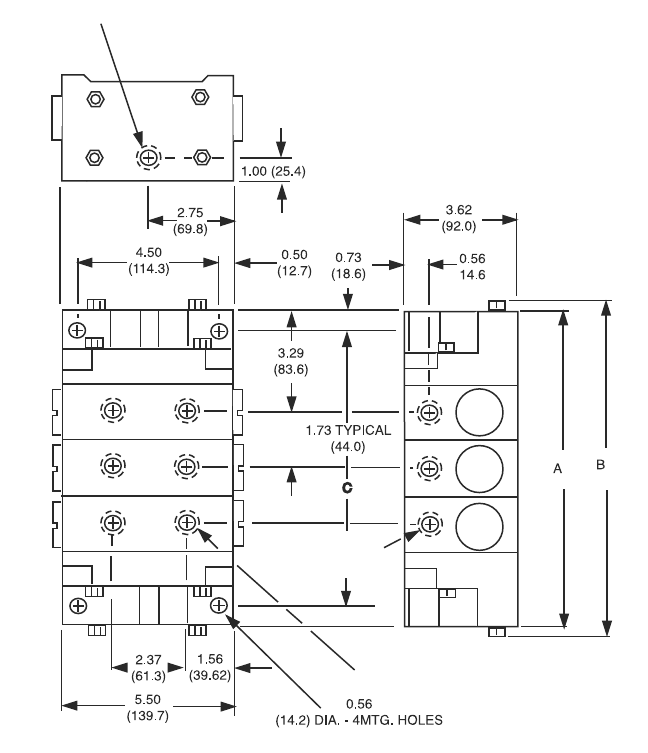
312497G 25
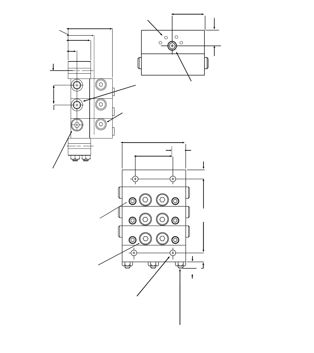
Dimensions
INDICATOR PORT
(TYPICAL)
,
MOUNTING SCREW
(TYPICAL)
LUBE
INLET
.281 (7.137) DIA
(4) MTG HOLES
3.000
(76.2)
1.750
(44.4)
"A"
2.188
(55.56)
1.656
(42.06)
1.500
(38.1)
.781
(19.9)
1.125
(28.58)
.406
(10.31)
.734
(18.85)
OUTLET IS PLUGGED
ON ONE SIDE WHEN
WORKING SECTION IS
SINGLED
LUBE
OUTLET
(TYPICAL)
PISTON ENCLOSURE PLUG (TYPICAL)
TIE ROD AND NUT
(TYPICAL)
.28
(7.1)
.484
(12.3)
.484
(12.3)
.625
(15.9)
.922 (TYP)
(23.41)
",%%$3#2%73
ti11480
MHH Series
26 312497G
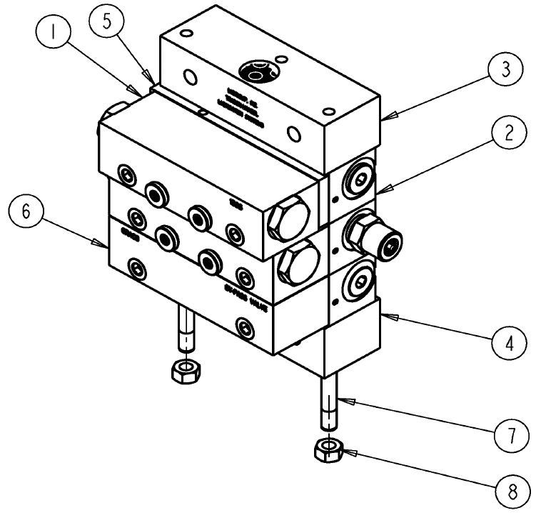
Parts
Ref Part No. Description
1 562679 VALVE, assembly MHH 06S
562680 VALVE, assembly MHH 09S
562681 VALVE, assembly MHH 12S
562682 VALVE, assembly MHH 18S
562683 VALVE, assembly MHH 24S
562684 VALVE, assembly MHH 30S
562685 VALVE, assembly MHH 06T
562686 VALVE, assembly MHH 09T
562687 VALVE, assembly MHH 12T
562688 VALVE, assembly MHH 18T
562689 VALVE, assembly MHH 24T
562690 VALVE, assembly MHH 30T
2 563425 BLOCK, base, MHH, NPSF
563447 BLOCK, base, MHH, BSPP
563451 BLOCK, base, MHH, SAE
563479 BLOCK, base, MHH w/no outlets
3 560919 BLOCK, inlet, MHH, NPSF
560936 BLOCK, inlet, MHH, BSPP
560943 BLOCK, inlet, MHH, SAE
560976 BLOCK, inlet, MHH, ISO 6149
563421 BLOCK, inlet, MHH, NPSF, w/bleed
563422 BLOCK, inlet, MHH SAE w/bleed
563451 BLOCK, base, MHH, SAE
4 563279 BLOCK, MHH end w/alt inlet
563424 BLOCK, end, MHH
5 563469 KIT, crossport bar, right
563470 KIT, crossport bar, left
563471 KIT, crossport bar, both
6 563472 KIT, singling bar
7 562660 VALVE, assembly bypass
8 557731 ROD, tie, 3 section (3 required)
557732 ROD, tie, 4 section (3 required)
557733 ROD, tie, 5 section (3 required)
557734 ROD, tie, 6 section (3 required)
557735 ROD, tie, 7 section, (3 required)
557736 ROD, tie, 8 section (3 required)
557738 ROD, tie, 9 section (3 required)
557739 ROD, tie, 10 section (3 required)
557740 ROD, tie, 11 section (3 required)
9 556371 NUT, 1/4 - 28 (3 required)
Ref Part No. Description
MXP Series
312497G 27
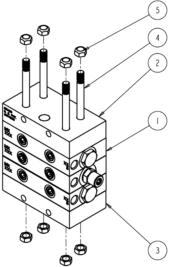
MXP Series
Technical Data
Material Zinc Plated Steel
Pressure (max) 3,000 psi (207 bar)
Lubricant Oil or grease
Maximum Operating Temperature 350°F (177°C)
Maximum Cycle Rate With Cycle Pin 60 CPM
Maximum Cycle Rate Without Cycle Pin or With Prox
Cycle Switch
200 CPM
Net Weight (approx.)
3 section divider valve assembly 18-lb. 2 oz (8.3 kg)
4 section divider valve assembly 22 lbs. 6 oz (10.2 kg)
5 section divider valve assembly 26 lbs. 9 oz (12.2 kg)
6 section divider valve assembly 31 lbs. 3 oz (14.2 kg)
7 section divider valve assembly 35 lbs. 6 oz (16.2 kg)
8 section divider valve assembly 39 lbs. 9 oz (18.1 kg)
9 section divider valve assembly 44 lbs. 3 oz (20.1 kg)
10 section divider valve assembly 48 lbs. 6 oz (22.1 kg)
Torque Ratings
Tie Rod Nut 6-9 ft. lbs
Enclosure Plugs 48 +/- 2 ft. lbs
Indicator Plug 12 -15 ft. lbs
Valve Section Mounting Screw 12-13 ft. lbs.
MXP Series
28 312497G
Dimensions
,5"%).,%4
).$)#!4/20/24
,5"%/54,%4
/04)/.!,
#2/330/240,!4%/04)/.!,
ti11477
MXP Series
312497G 29
Parts
Ref Part No. Description
1 562813 VALVE, twin, .025 MXP
562814 VALVE, twin, .050 MXP
562815 VALVE, twin, .075 MXP
562816 VALVE, twin, .100 MXP
562817 VALVE, twin, .125 MXP
562818 VALVE, twin, .150 MXP
562819 VALVE, single, .025 MXP
562820 VALVE, single, .050 MXP
562821 VALVE, single, .075 MXP
562822 VALVE, single, .100 MXP
562823 VALVE, single, .125 MXP
562824 VALVE, single, .150 MXP
562825 VALVE, twin, .050 MXP w/indicator
562826 VALVE, twin, .075 MXP w/indicator
562827 VALVE, twin, .100 MXP w/indicator
562828 VALVE, twin, .125 MXP w/indicator
562829 VALVE, twin, .150 MXP w/indicator
562830 VALVE, single, .050 MXP w/indicator
562831 VALVE, single, .075 MXP w/indicator
562832 VALVE, single, .100 MXP w/indicator
562833 VALVE, single, .125 MXP w/indicator
562834 VALVE, single, .150 MXP w/indicator
2 563519 BLOCK, BSPLT interm MXP 1/4 NPSF
563521 BLOCK, BSPLT interm MXP SAE
563522 BLOCK, BSPLT interm MXP 1/4 BSPP
563479 BLOCK, base, MSP/MHH w/no outlets
3 56R994 BLOCK, inlet, MXP
4 563518 BLOCK, end, machine MX
5 563524 KIT, MXP, crossport bar, left
563525 KIT, MXP, crossport bar, right
563526 KIT, MXP, crossport bar, both
6 15R997 BLOCK, bypass, MXP
7 557766 ROD, tie, 3 section, MXP (3 required)
557767 ROD, tie, 4 section, MXP (3 required)
557768 ROD, tie, 5 section, MXP (3 required)
557769 ROD, tie, 6 section, MXP (3 required)
557770 ROD, tie, 7 section, MXP (3 required)
557771 ROD, tie, 8 section, MXP (3 required)
557772 ROD, tie, 9 section, MXP (3 required)
563520 ROD, tie, 10 section, MXP (3 required)
8 555406 NUT, 5/16 - 24 light hex (3 required)
Ref Part No. Description
MGO Series
30 312497G
MGO Series
Technical Data
Material Zinc Plated Steel and Phosphate Coated Cast Iron
Pressure (max)
3-7 section divider valve assembly 6000 psi (414 bar)
8 section divider valve assembly 5500 psi (380 bar)
9 section divider valve assembly 5000 psi (345 bar)
10 section divider valve assembly 4500 psi (311 bar)
11 section divider valve assembly 4000 psi (276 bar)
Lubricant Oil or grease
Maximum Operating Temperature 200°F (93°C)
Maximum Cycle Rate With Cycle Pin 60 CPM
Maximum Cycle Rate Without Cycle Pin or With Prox
Cycle Switch
200 CPM
Net Weight (approx.)
3 section divider valve assembly 45-lb. (20.41 kg)
4 section divider valve assembly 53 lbs. 5 oz (24.18 kg)
5 section divider valve assembly 61 lbs. 10 oz (27.95 kg)
6 section divider valve assembly 70 lbs. 15 oz (32.17 kg)
7 section divider valve assembly 80 lbs. 4 oz (36.40 kg)
8 section divider valve assembly 89 lbs. 9 oz (40.62 kg)
9 section divider valve assembly 98 lbs. 14 oz (44.84 kg)
10 section divider valve assembly 108 lbs. 3 oz (49.07 kg)
11 section divider valve assembly 117 lbs. 8 oz (53.40 kg)
Torque Ratings
Tie Rod Nut 12 ft. lbs
Enclosure Plug 15 ft. lbs
Outlet Port Plug 6-8 ft. lbs
Valve Section Mounting Screw 12-13 ft. lbs.
MGO Series
312497G 31
Dimensions
).,%4
/54,%43
).$)#!4/20/243
MGO Series
32 312497G
Parts
Ref Part No. Description
1 562570 VALVE, MGO, assembly 150S SAE
562571 VALVE, MGO, assembly 300S SAE
562572 VALVE, MGO, assembly 450S SAE
562573 VALVE, MGO, assembly 600S SAE
562574 VALVE, MGO, assembly 150T SAE
562575 VALVE, MGO, assembly 300TS SAE
562576 VALVE, MGO, assembly 450T SAE
562577 VALVE, MGO, assembly 600T SAE
562578 VALVE, MGO, assembly 150S SAE IND
562579 VALVE, MGO, assembly 300S SAE IND
562580 VALVE, MGO, assembly 450S SAE IND
562581 VALVE, MGO, assembly 6000S SAE IND
562582 VALVE, MGO, assembly 150T SAE IND
562583 VALVE, MGO, assembly 300T SAE IND
562584 VALVE, MGO, assembly 450T SAE IND
562585 VALVE, MGO, assembly 600T SAE IND
2 563277 INLET,
3 563278 END
4 560591 ROD, tie, short MGO 3 (2 required)
560592 ROD, tie, short MGO 4 (2 required)
560593 ROD, tie, short MGO 5 (2 required)
560594 ROD, tie, short MGO 6 (2 required)
560595 ROD, tie, short MGO 7 (2 required)
560596 ROD, tie, short MGO 8 (2 required)
560597 ROD, tie, short MGO 9 (2 required)
560598 ROD, tie, short MGO 10 (2 required)
560599 ROD, tie, short MGO 11 (2 required)
5 560600 ROD, tie, long MGO 3 (2 required)
560601 ROD, tie, long MGO 4 (2 required)
560602 ROD, tie, long MGO 5 (2 required)
560603 ROD, tie, long MGO 6 (2 required)
15U857 ROD, tie, long MGO 7 (2 required)
560604 ROD, tie, long MGO 8 (2 required)
560605 ROD, tie, long MGO 9 (2 required)
560606 ROD, tie, long MGO 10 (2 required)
560607 ROD, tie, long MGO 11 (2 required)
6 555406 NUT, tie rod 3/8 - 24 lock (8 required)
MX Series
312497G 33
MX Series
Technical Data
Material Plated Steel
Pressure (max) 3,000 psi (207 bar)
Lubricant Oil or grease
Maximum Operating Temperature 200°F (93°C)
Maximum Cycle Rate With Cycle Pin 60 CPM
Maximum Cycle Rate Without Cycle Pin 200 CPM
Net Weight (approx.)
3 section divider valve assembly 21-lb. 6 oz (9.69 kg)
4 section divider valve assembly 25 lbs. 10 oz (11.62 kg)
5 section divider valve assembly 29 lbs. 14 oz (13.55 kg)
6 section divider valve assembly 34 lbs. 2 oz (15.47 kg)
7 section divider valve assembly 38 lbs. 6 oz (17.40 kg)
8 section divider valve assembly 42 lbs. 12 oz (19.39 kg)
9 section divider valve assembly 47 lbs. 2 oz (21.37 kg)
10 section divider valve assembly 51 lbs. 8 oz (23.26 kg)
Torque Ratings
Tie Rod Nut 30 ft. lbs
Enclosure Plug 48 ft. lbs
Outlet Port Plugs 18 ft. lbs.
MX Series
34 312497G
Dimensions
v/54,%4
ti11476
MX Series
312497G 35
Parts
Ref Part No. Description
1 562514 VALVE, MX assembly 25S
562515 VALVE, MX assembly 25T
562516 VALVE, MX assembly 50S
562517 VALVE, MX assembly 50T
562538 VALVE, MX assembly 75S
562539 VALVE, MX assembly 75T
562540 VALVE, MX assembly 100S
562541 VALVE, MX assembly 100T
562542 VALVE, MX assembly 125S
562543 VALVE, MX assembly 125T
562545 VALVE, MX assembly 150S
562546 VALVE, MX assembly 150T
562528 VALVE, MX assembly 50S IND LH
562518 VALVE, MX assembly 50S IND RH
562533 VALVE, MX assembly 50T IND LH
562523 VALVE, MX assembly 50T IND RH
562529 VALVE, MX assembly 75S IND LH
562519 VALVE, MX assembly 75S IND RH
562534 VALVE, MX assembly 75T IND LH
562524 VALVE, MX assembly 75T IND RH
562530 VALVE, MX assembly 100S IND LH
562520 VALVE, MX assembly 100S IND RH
562569 VALVE, MX assembly 100T IND LH
562525 VALVE, MX assembly 100T IND RH
562531 VALVE, MX assembly 125S IND LH
562521 VALVE, MX assembly 125S IND RH
562535 VALVE, MX assembly 125T IND LH
562526 VALVE, MX assembly 125T IND RH
562532 VALVE, MX assembly 150S IND LH
562522 VALVE, MX assembly 150S IND RH
562536 VALVE, MX assembly 150T IND LH
562527 VALVE, MX assembly 150T IND RH
2 560620 BLOCK, inlet
3 563287 BLOCK, end
4 557488 ROD, tie, MX 3 (4 required)
557489 ROD, tie, MX 4 (4 required)
557490 ROD, tie, MX 5 (4 required)
557491 ROD, tie, MX 6 (4 required)
557492 ROD, MX 7 (4 required)
557493 ROD, tie, MX 8 (4 required)
560576 ROD, tie, MX 9 (4 required)
560577 ROD, tie, MX 10 (4 required)
5 557494 NUT, tie rod 3/8 - 24 lock (8 required)
MX Series
36 312497G

Accessories
312497G 37
Accessories
Tube Clips
Clips are plated and provided with 17/64” (6.75 mm)
mounting holes.
Mounting Bars
Mounting Brackets
All mounting brackets include screws, lock washers and
nuts.
Performance Indicators
Performance indicators are pressure sensitive devices that signals a fault when there is excessive build up of pres-
sure in a series progressive lubricating system. A fault is identified by either causing a pin to protrude or by releasing
lubricant to the atmosphere.
Reset Indicator with Memory
Reset Indicators stop lube system operation when a fault occurs. They can be used in either master or secondary
divider valves. Fault is indicated when a pin protrudes through the opening in the cap and is manually reset.
Part No. Description
557324 Holds 1 - 1/4” (6.35 mm) OD tube
558711 Holds 1 - 3/8” (9.52 mm) OD tube
558710 Holds 3 - 1/4” (6.35 mm) OD tube
Part No. Description
560920 MSP, 1/2” (12.7 mm) thick, 1/4-20 thread
561101 MJ, 1/2” (12.7 mm) thick, 10-24 thread
561102 MX and MXP, 1/2” (12.7 mm) thick, 5/16-18
threads, two sets of mounting holes
563465 KIT, mounting bar, includes 2 mounting bars,
4 screws, washers and lock washers
Part No. Description
563435 MSP and MH, M-3 and M-4, 1/8” (3.175 mm)
thick, top mounting.
563436 MSP and MH, M5 and M-6, 1/8” (3.175 mm)
thick, top mounting
563437 MSP and MH, M7 and M-8, 1/8” (3.175 mm)
thick, top mounting
563438 MSP and MH, M-3 and M-4, 1/8” (3.175 mm)
thick, side mounting.
563439 MSP and MH, M5 and M-6, 1/8” (3.175 mm)
thick, side mounting
563440 MSP and MH, M7 and M-8, 1/8” (3.175 mm)
thick, side mounting
Pressure PSI
Description
1/8” NPTF
MJ, MH, MS, MXP
1/8” NPSF
w/O-Ring
MH, MS, MXP
Nickel Plated
1/8” NPTF
MJ, MH, MS, MXP
1/4” NPTF
MX Only
7/8” SAE
w/O-Ring
MGO
250 563231 563252 NA 563239 NA
500 563232 563253 563246 563240 NA
750 563233 563254 NA 563241 NA
1000 563234 563255 563247 563242 NA
1500 563235 563256 563248 563243 564200
2000 563236 563257 NA 563244 NA
2500 563237 563258 563249 563245 NA
3000 NA 563261 NA NA NA
5000 NA 563262 NA NA NA
Accessories
38 312497G
Automatic Relief Indicator
Automatic Relief Indicators pinpoint lube line blockage but allow the lube system to continue to supply lubrication to
points that are not blocked. They are used primarily in secondary divider valves. When needed, pressure is relieved
through a vent. When pressure is relieved the spring resets the piston. Because these indicators permit the lube sys-
tem to continue operating when a lube point is blocked, a separate pressure switch connected to an audible or visual
alarm should be used to warn of high pressure.
Rupture Indicator - MH Divider Valves Only
Rupture Indicators are only used on MH divider valve applications where lube system pressures exceed 2500 psi.
The high pressure from a lube line blockage causes a disc to rupture. The lubricant then forces an indicator pin to
protrude, locating the blockage. The high pressure backs up through the system and trips a switch to shut the system
off. When the fault is corrected, the disc must be replaced the pin reset manually.
Pressure PSI Color*
Description
1/8” NPTF
MJ, MH, MS, MXP
1/8” NPSF
w/O-Ring
MH, MS, MXP
1/4” NPTF
MX Only
750 + 20% Blue 563163 563170 563156
1000 + 20% Green 563164 563171 563157
1250 + 20% Yellow 563165 563172 NA
1500 + 20% Red 563166 563173 563158
2000 + 20% Orange 563167 563174 563159
2500 + 20% Aluminum 563168 563175 563160
3000 + 24% Purple 563169 563176 563161
* Color provided for reference only to aid in selection of replacement indicator. Indicators used to be
identified by the color of the spring retainer located in the end of the indicator.
Pressure PSI
Description
1/8” - 27 NPTF 1/8” - 27 NPSF
w/O-Ring Disc Color Replacement Disc
3/8” Diameter
2800 + 20% 563228 563229 Green 557422
3700 + 20% 563220 563221 Yellow 557423
4600 + 20% 564355 563222 Red 557424
5500 + 20% 563223 563224 Orange 557425
6400 + 20% 563225 563226 Pink 557427
7300 + 20% 563227 NA Blue 557428
8200 + 20% NA NA Purple 557429

Accessories
312497G 39
Rupture-to-Atmosphere Indicator
Rupture-to-Atmosphere Indicators are standard on all Graco pumps. When the pressure reaches a predetermined
pressure setting, the pressure disc ruptures, venting lubricant into the atmosphere and relieving pressure.
Rupture-to-Atmosphere Indicator with Spud Assembly
A Spud Assembly is available to return vented lubricant to the reservoir by way of a tube. A high pressure switch is
recommended to provide an audible or visual warning alarm that height system pressure has occurred.
Pressure PSI*
Description
Complete Assembly Replacement Disc Color Blowout Disc
1/4” NPTF Fittings 11/16” Diameter Quantity = 6
900 NA 557431 Black NA
1450 563179 557433 Yellow 563962
1750 563182 557434 Red 563963
2050 563183 557435 Orange 563964
2350 563184 557436 Aluminum 563965
2650 NA 557467 Pink NA
2950 563185 557438 Blue 563966
3250 NA 557439 Purple NA
1/8” NPTF Fittings 3/8” Diameter Quantity = 25
900 NA 555788 Black 563952
1450 NA 557423 Yellow 563954
1750 564059 557424 Red 563955
2050 NA 557425 Orange 563956
2350 563191 557426 Aluminum 563957
2650 NA 557427 Pink 563958
2950 563192 557428 Blue 563959
3250 563193 557429 Purple 563960
5000 563194 557430 Brown 563961
High Pressure
1/8” NPTF Fittings 3/8” Diameter Quantity = 25
3700 564479 557423 Yellow 563954
4600 563216 557424 Red 563955
5500 563217 557425 Orange 563956
6400 563218 557427 Pink 563958
7300 563219 557428 Blue 563959
8200 NA 557429 Purple 563960
9500 NA NA Gray NA
Pressure PSI*
Description
Complete Assembly Replacement Disc Color
1450 563186 557433 Yellow
1750 563187 557434 Red
2350 563188 557436 Aluminum
*All pressures have a tolerance of + 500 psi.
Accessories
40 312497G
Rupture Discs
All discs are 11/16” diameter.
Singling and Crossporting Bar Assemblies
Singling Kits externally convert a “T” (Twin Outlet) section to an “S” (Single Outlet) section.
Crossporting Kits externally combine the output of two (2) adjacent sections.
Cycle Indicators
Cycle Indicators provide a means of visually monitoring lube flow thru the system.
The pin type cycles in and out when lubricant is flowing. Movement of the pin is caused by the piston (the two are
attached) so that when the piston moves the indicator pin in and out once, the entire divider valve has cycled.
Pressure PSI*
Description
Single Disc Disc Color Quantity 6/package
900 557431 Black NA
1175 557432 Green NA
1450 557433 Yellow 563962
1750 557434 Red 563963
2050 557435 Orange 563964
2350 557436 Aluminum 563965
2650 557437 Pink NA
2950 557438 Blue 563966
3250 557439 Purple NA
*All pressures have a tolerance of + 500 psi.
Part Numbers
Divider Single Kit Right Side Left Side O-Ring
Gasket
Upper Seal
(Bar Type)
Gasket
Lower Seal
(Bar Type)
90 Duro
Fluoroelastomer
O-Ring (plate
Type)
Valve Block
Mounting
Screw-Long
MJ 562915 562914 562914 NA 557359 557403 NA NA
MJ-SS NA NA NA NA NA NA NA NA
MSP 563469 563469 563470 563471 NA NA 557722 556514
MS (Nickel) NA NA NA NA NA NA NA NA
MX 52916 52917 52917 NA 55711 55712 NA NA
MXP NA 563525 563524 56e526 NA NA 557773 555601
MXP (Nickel) NA NA NA NA NA NA NA NA
MGO NA NA NA NA NA NA NA NA
Valve Series O-Ring Sealed
MS/MH 563251
MX/MXP 563260
MGO NA

Accessories
312497G 41
Cycle Counters - Part No.: 563444
The purpose of a cycle counter is to give assurance that the lubricant is flowing thru the system. Every “count” indi-
cates one complete cycle of the divider valve. Visual inspection and/or recording of counts provides a constant check
on the performance of your lubricant system and the pump. The Cycle Counter can be used on any MJ, MS, MH, MX
and MXP divider valve assembly.
Cycle Switches
The function of a Cycle Switch is to electrically give assurance that the lubricant is flowing through the system. Actu-
ated by a cycle pin, the switch can be wired to various controls.
NOTE: The cycle switch MUST be attached to a section that is equipped with a cycle indicator pin.
Part Numbers
Series Flo Divider Valves MJ MS/MH MS (Nickel) MX MXP MGO
Cycle Switch and Bracket Assembly
SPDT
563272 563272 563272 563272 563272 563269
Electrical Ratings: 15 amps at 125, 250 and 480 VAC; 1/2 amp at 125 VDC, 1/4
amp at 250 VDC, 6.0 amp at 24 VDC Non-Inductive
Replacement Switch 557781 557781 557781 557781 557781 557781
Cycle Switch and Bracket Assembly
DPDT
564357 564357 564537 564357 564537 NA
Electrical Ratings: 10 amps at 125 or 250 VAC; 0.3 amp at 125 VDC or 0.15 amp
at 250 VDC
Replacement Switch NA NA NA NA NA NA
Replacement Bracket for either
SPDT or DPDT Switch Assembly 557546 557546 557546 557546 557546 560573
Moisture Resistant Cycle Switch
with 6-foot Cable and Bracket
Assembly SPDT
563273 563273 563273 563273 563273 NA
Electrical Ratings: 5 amps at 125 or 250 VAC; Wire Code for Moisture Resistant
Switch: BK (Com), Red (N.C), WH (N.O.), GN (Ground)
Replacement Switch with 6-foot
Cable 557782 557782 557782 557782 557782 NA

Accessories
42 312497G
Proximity Cycle Switches
The Proximity Cycle Switches are magnetically operated single throw switches that sense the movement of the
divider valve piston when it is cycling. Each proximity cycle switch provides a signal that is used to monitor the sys-
tem. There are 3 different types of switches available.
Reed Type Proximity Switch: Can be used with oil applications only for MS, MH and MGO divider valves at pres-
sures up to 518 bar (7500 psi) at cycle rates under 60 cycles per minute.
Field Sensitive Magnetic Proximity Switch: Dry contact, ceramic magnet operated switch. Used at pressures that
do not exceed 242 bar (3500 psi) at cycle rates up to 200 cycles per minute. Used in MS/MH, MX/MXP and MGO
divider valves. An explosion proof version for MS/MH divider valves is available.
Magnetic Operated Proximity Switch: Not limited to valve size. Miniature snap-action switch is tripped by attraction
of internal magnet to the moving divider piston. Can be used at pressures up to 518 bar (7500 psi) at cycle rates that
do not exceed 150 cycles per minute.
*Consult your distributor for availability.
Description No.
of Pins
Type
Seal
Part Number
MS MH MX MXP MGO
Unattached Reed Type (oil only)
10mA @ 120VAC
24 mA @ 24VDC
10,000,000 Cycle Life
1/2 NPT with
Leads
(Explosion
Proof)
O-Ring 563427 563427 NA NA NA
Field Sensitive Magnetic Type
3-pin and 5-pin (AC only)
2A @ 120/240 VAC
4-pin (DC only) 0.1A @ 28VDC
150,000,000 Cycle Life
3O-Ring 557741 557741 563476 563476 563970
Gasket*NANANANANA
5O-Ring 557746 557746 564399 564399 NA
Gasket*NANANANANA
4 O-Ring 557747 557747 558939 558939 563495
Pigtail Lead
(Explosion
Proof)
O-Ring 557745 557745 564401 564401 NA
Magnetic Type with LED’s
5A @ 24 VDC
10,000,000 Cycle Life
3 O-Ring 563478 563478 NA NA NA
5 O-Ring 563477 563477 NA NA NA
Magnetic Type
5A @ 24VDC
5A @ 120/240 VAC
10,000,000 Cycle Life
3 Gasket* NA NA 563486 563486 NA
5 O-Ring 563484 563484 564400 564400 NA
Pigtail Lead
(Explosion
Proof)
O-Ring 563485 563485 NA NA NA
Field Sensitive Magnetic Type
25 mA @ 24VDC
M12 x 1, 4-pin (DC only)
10,000,000, cycle life
4 O-Ring 563500 563501 NA NA NA

Accessories
312497G 43
Proximity Switch Connection Cables
Connection Cables for:
3-Pin Proximity Switch 5-Pin Proximity Switch
Connector Length - ft (m) Part No. Connector Length - ft (m) Part No.
Straight 6 (1.83) 558021 Straight 6 (1.83) 558023
Straight 12 (3.66) 558022 Straight 12 (3.66) 558024
NA NA NA 90° 6 (1.83) 558965
4-Pin Proximity Switch
Straight 7 (2.13) 568738 NA NA NA
All written and visual data contained in this document reflects the latest product information available at the time of publication.
Graco reserves the right to make changes at any time without notice.
Original instructions. This manual contains English. MM 312497
Graco Headquarters: Minneapolis
International Offices: Belgium, China, Japan, Korea
GRACO INC. AND SUBSIDIARIES • P.O. BOX 1441 • MINNEAPOLIS MN 55440-1441 • USA
Copyright 2009, Graco Inc. All Graco manufacturing locations are registered to ISO 9001.
www.graco.com
Revised 1/2012
Graco Standard Warranty
Graco warrants all equipment referenced in this document which is manufactured by Graco and bearing its name to be free from defects in
material and workmanship on the date of sale to the original purchaser for use. With the exception of any special, extended, or limited warranty
published by Graco, Graco will, for a period of twelve months from the date of sale, repair or replace any part of the equipment determined by
Graco to be defective. This warranty applies only when the equipment is installed, operated and maintained in accordance with Graco’s written
recommendations.
This warranty does not cover, and Graco shall not be liable for general wear and tear, or any malfunction, damage or wear caused by faulty
installation, misapplication, abrasion, corrosion, inadequate or improper maintenance, negligence, accident, tampering, or substitution of
non-Graco component parts. Nor shall Graco be liable for malfunction, damage or wear caused by the incompatibility of Graco equipment with
structures, accessories, equipment or materials not supplied by Graco, or the improper design, manufacture, installation, operation or
maintenance of structures, accessories, equipment or materials not supplied by Graco.
This warranty is conditioned upon the prepaid return of the equipment claimed to be defective to an authorized Graco distributor for verification of
the claimed defect. If the claimed defect is verified, Graco will repair or replace free of charge any defective parts. The equipment will be returned
to the original purchaser transportation prepaid. If inspection of the equipment does not disclose any defect in material or workmanship, repairs will
be made at a reasonable charge, which charges may include the costs of parts, labor, and transportation.
THIS WARRANTY IS EXCLUSIVE, AND IS IN LIEU OF ANY OTHER WARRANTIES, EXPRESS OR IMPLIED, INCLUDING BUT NOT LIMITED
TO WARRANTY OF MERCHANTABILITY OR WARRANTY OF FITNESS FOR A PARTICULAR PURPOSE.
Graco’s sole obligation and buyer’s sole remedy for any breach of warranty shall be as set forth above. The buyer agrees that no other remedy
(including, but not limited to, incidental or consequential damages for lost profits, lost sales, injury to person or property, or any other incidental or
consequential loss) shall be available. Any action for breach of warranty must be brought within two (2) years of the date of sale.
GRACO MAKES NO WARRANTY, AND DISCLAIMS ALL IMPLIED WARRANTIES OF MERCHANTABILITY AND FITNESS FOR A
PARTICULAR PURPOSE, IN CONNECTION WITH ACCESSORIES, EQUIPMENT, MATERIALS OR COMPONENTS SOLD BUT NOT
MANUFACTURED BY GRACO. These items sold, but not manufactured by Graco (such as electric motors, switches, hose, etc.), are subject to
the warranty, if any, of their manufacturer. Graco will provide purchaser with reasonable assistance in making any claim for breach of these
warranties.
In no event will Graco be liable for indirect, incidental, special or consequential damages resulting from Graco supplying equipment hereunder, or
the furnishing, performance, or use of any products or other goods sold hereto, whether due to a breach of contract, breach of warranty, the
negligence of Graco, or otherwise.
FOR GRACO CANADA CUSTOMERS
The Parties acknowledge that they have required that the present document, as well as all documents, notices and legal proceedings entered into,
given or instituted pursuant hereto or relating directly or indirectly hereto, be drawn up in English. Les parties reconnaissent avoir convenu que la
rédaction du présente document sera en Anglais, ainsi que tous documents, avis et procédures judiciaires exécutés, donnés ou intentés, à la suite
de ou en rapport, directement ou indirectement, avec les procédures concernées.
Graco Information
For the latest information about Graco products, visit www.graco.com.
TO PLACE AN ORDER, contact your Graco distributor or call to identify the nearest distributor.
Phone: 612-623-6928 or Toll Free: 1-800-533-9655, Fax: 612-378-3590
