Graco 307517T Mastic Fluid Regulators Users Manual Regulators, Instructions Parts, English
2015-04-02
: Graco Graco-307517T-Mastic-Fluid-Regulators-Users-Manual-686529 graco-307517t-mastic-fluid-regulators-users-manual-686529 graco pdf
Open the PDF directly: View PDF ![]() .
.
Page Count: 34
Instructions–Parts List
307517T
ENG
Important Safety Instructions
Read all warnings and instructions in this manual.
Save these instructions.
See page 2 for List of Models and Table of Contents.
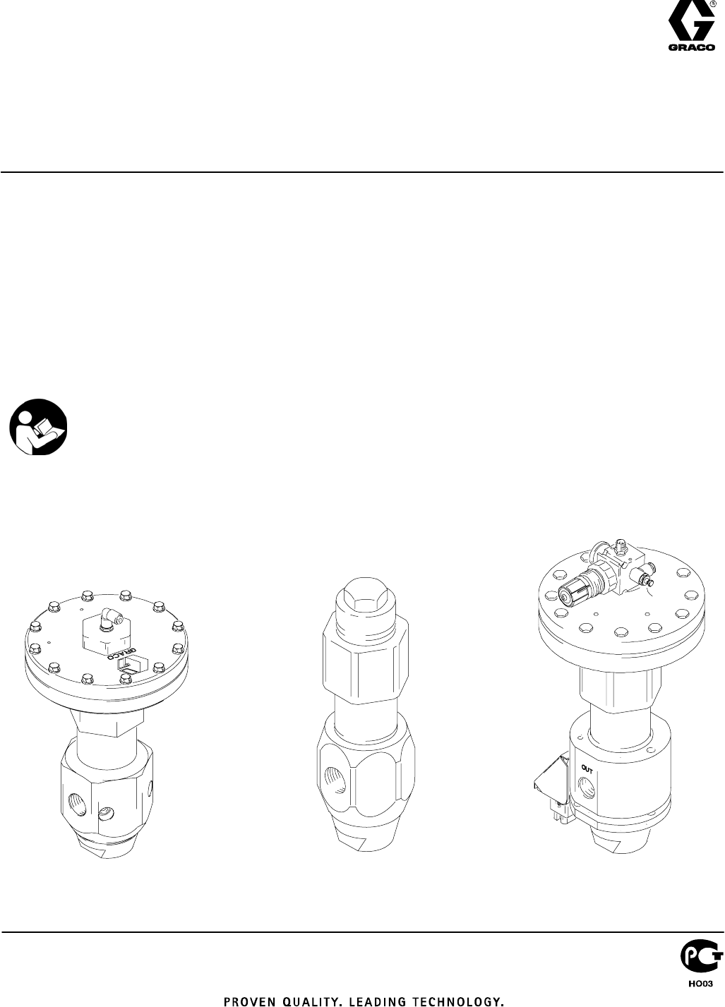
Spring-Operated and Air-Operated, High Pressure
Mastic Fluid Regulators
5000 psi (34.4 MPa, 344 bar) Maximum
Inbound Fluid Pressure
These regulators control downstream pressure for
mastic or semi-solid material. Install a regulator ahead of
each spray gun or extruder gun in a multiple outlet
system. The regulator provides precise pressure control
to each spray gun from a common header system. It
also dampens flow surges when line valves are opened
and during pump stroke changeover.
Model 903958
TI1371
Model 244740
TI0345
Model 243700

2 307517
Table of Contents
Warnings 3. . . . . . . . . . . . . . . . . . . . . . . . . . . . . . . . . . . . . .
Installation 6. . . . . . . . . . . . . . . . . . . . . . . . . . . . . . . . . . . . .
Operation 7. . . . . . . . . . . . . . . . . . . . . . . . . . . . . . . . . . . . .
Maintenance 8. . . . . . . . . . . . . . . . . . . . . . . . . . . . . . . . . . .
Parts 10. . . . . . . . . . . . . . . . . . . . . . . . . . . . . . . . . . . . . . . .
Dimensions 30. . . . . . . . . . . . . . . . . . . . . . . . . . . . . . . . . . .
Wiring Diagram 31. . . . . . . . . . . . . . . . . . . . . . . . . . . . . . .
Technical Data 32. . . . . . . . . . . . . . . . . . . . . . . . . . . . . . . .
Accessories 33. . . . . . . . . . . . . . . . . . . . . . . . . . . . . . . . . .
Graco Standard Warranty 34. . . . . . . . . . . . . . . . . . . . . .
Graco Information 34. . . . . . . . . . . . . . . . . . . . . . . . . . . . .
List of Ambient Models
Part
No. Series Regulator
Operation Regulated Fluid
Pressure Maximum Inbound
Air Pressure Parts
Page
903958 Series B Spring-operated,
high range (low
range spring is avail-
able, see page 33)
1000–4500 psi (7.0–31.0
MPa, 70–310 bar) 12
961635 Series C Air-operated 250–4500 psi (2.8–31.0
MPa, 17–310 bar) 100 psi (0.7 MPa, 7 bar) 12
244740 Series A Air–operated 250–4500 psi (2.8–31.0
MPa, 17–310 bar) 100 psi (0.7 MPa, 7 bar) 14
C58318 Series A Air-operated 250–4500 psi (2.8–31.0
MPa, 17–310 bar) 100 psi (0.7 MPa, 7 bar) 16
246642 Series A Air–operated 100–4500 psi (0.7–31.0
MPa, 7–310 bar) 100 psi (0.7 MPa, 7 bar) 22
246687 Series A Air–operated 100–4500 psi (0.7–31.0
MPa, 7–310 bar) 100 psi (0.7 MPa, 7 bar) 24
262549 Series A Air–operated 100–2600 psi (0.7–18.0
MPa, 7–180 bar) 60 psi (0.4 MPa, 4 bar) 24
List of Temperature Conditioned/Heated
Models
Part
No. Heat
Method Regulator
Operation Regulated Fluid
Pressure Maximum Inbound
Air Pressure Parts
Page
243700 240 VAC Air-operated 250–3500 psi (1.7–24.1
MPa, 17–241 bar) 65 psi (0.45 MPa, 4.5 bar) 10
C07720 Ambient Air-operated 250–3500 psi (1.7–24.1
MPa, 17–241 bar) 65 psi (0.45 MPa, 4.5 bar) 18
918447 120 VAC Air–operated
(Mounting Bracket
Kit Available)
250–3500 psi (1.7–24.1
MPa, 17–241 bar) 65 psi (0.45 MPa, 4.5 bar) 20
246643 240 VAC Air-operated 100–3500 psi (0.7–24.1
MPa, 7–241 bar) 65 psi (0.45 MPa, 4.5 bar) 26
246688 240 VAC Air-operated 100–3500 psi (0.7–24.1
MPa, 7–241 bar) 65 psi (0.45 MPa, 4.5 bar) 28
3307517
Symbols
Warning Symbol
WARNING
This symbol alerts you to the possibility of serious
injury or death if you do not follow the instructions.
Caution Symbol
CAUTION
This symbol alerts you to the possibility of damage to
or destruction of equipment if you do not follow the
corresponding instructions.
WARNING
SKIN INJECTION HAZARD
Spray from the gun, hose leaks, or ruptured components can inject fluid into your body and cause an
extremely serious injury, including the need for amputation. Splashing fluid in the eyes or on the skin
can also cause a serious injury.
DFluid injected into the skin might look like just a cut, but it is a serious injury. Get immediate surgi-
cal treatment.
DDo not point the spray gun/dispensing valve at anyone or at any part of the body.
DDo not put hand or fingers over the spray tip/nozzle.
DDo not stop or deflect fluid leaks with your hand, body, glove, or rag.
DDo not “blow back” fluid; this is not an air spray system.
DAlways have the tip guard and the trigger guard on the spray gun/dispensing valve when spraying/
dispensing.
DBe sure the gun trigger safety operates before spraying.
DLock the gun/valve trigger safety when you stop spraying.
DFollow the Pressure Relief Procedure in your separate equipment manuals whenever you: are
instructed to relieve pressure; stop spraying; clean, check, or service the equipment; and install or
clean the spray tip.
DTighten all the fluid connections before operating the equipment.
DCheck the hoses, tubes, and couplings daily. Replace worn, damaged, or loose parts immediately.
Permanently coupled hoses cannot be repaired; replace the entire hose.
Warnings are continued on the next page.

4 307517
WARNING
FIRE AND EXPLOSION HAZARD
Improper grounding, poor air ventilation, open flames, or sparks can cause a hazardous condition and
result in fire or explosion and serious injury.
DGround all equipment in the work area. See Grounding in your separate system manual.
DProvide fresh air ventilation to avoid the buildup of flammable fumes from solvent or the fluid being
sprayed.
DExtinguish all the open flames or pilot lights in the spray/dispensing area.
DElectrically disconnect all the equipment in the spray/dispensing area.
DKeep the spray/dispensing area free of debris, including solvent, rags, and gasoline.
DDo not turn on or off any light switch in the spray/dispensing area while operating or if fumes are
present.
DDo not smoke in the spray/dispensing area.
DDo not operate a gasoline engine in the spray/dispensing area.
DIf there is any static sparking while using the equipment, stop spraying/dispensing immediately.
Identify and correct the problem.
DKeep a fire extinguisher in the work area.
TOXIC FLUID HAZARD
Hazardous fluids or toxic fumes can cause a serious injury or death if splashed in the eyes or on the
skin, swallowed, or inhaled.
DKnow the specific hazards of the fluid you are using. Read the fluid manufacturer’s warnings.
DStore hazardous fluid in an approved container. Dispose of the hazardous fluid according to all
local, state, and national guidelines.
DWear appropriate protective clothing, gloves, eyewear, and respirator.
Warnings are continued on the next page.
5307517
WARNING
INSTRUCTIONS
EQUIPMENT MISUSE HAZARD
Equipment misuse can cause the equipment to rupture, malfunction, or start unexpectedly and result
in a serious injury.
DThis equipment is for professional use only.
DRead all the instruction manuals, tags, and labels before operating the equipment.
DUse the equipment only for its intended purpose. If you are uncertain about usage, call your Graco
distributor.
DDo not alter or modify this equipment. Use only genuine Graco parts and accessories.
DCheck the equipment daily. Repair or replace worn or damaged parts immediately.
DDo not exceed the maximum working pressure of the lowest rated system component. This equip-
ment has a 5000 psi (34.4 MPa, 344 bar) maximum inbound fluid pressure.
DUse fluids that are compatible with the equipment wetted parts. See the Technical Data section of
all the equipment manuals. Read the fluid manufacturer’s warnings.
DRoute the hoses away from traffic areas, sharp edges, moving parts, and hot surfaces. Do not
expose Graco hoses to temperatures above 180_F (82_C) or below –40_F (–40_C).
DDo not kink or over bend the hoses or use the hoses to pull equipment.
DWear hearing protection when operating this equipment.
DComply with all applicable local, state, and national fire, electrical, and other safety regulations.
DIf your spray or extruder gun has a lower pressure rating than the pump, be sure you adjust its fluid
regulator low enough to avoid exceeding the gun’s maximum working pressure.
MOVING PARTS HAZARD
Moving parts, such as the air motor piston, can pinch or amputate fingers.
DDo not operate the equipment with the air motor plates removed.
DKeep clear of any moving parts when starting or operating the equipment.
HOT SURFACE AND FLUID HAZARD
Heated fluid can cause severe burns and can cause equipment surfaces to become very hot.
DWear protective gloves and clothing when operating this equipment in a heated system.
DDo not touch the metal heat sink when the surface is hot.
DAllow the equipment to cool thoroughly before servicing.
Some heated systems are designed to dispense Polyurethane (PUR) heated materials. PUR systems
are supplied with ventilation hoods, and require proper ventilation and specially designed system
components.
6 307517
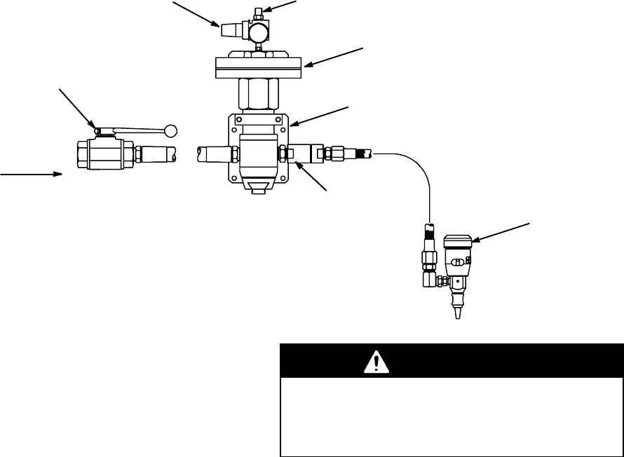
Installation
Applicator
Fluid from Pump
Fluid Regulator
Wall Bracket
Air Supply
Check Valve
Fluid Shutoff Valve
Air Regulator
Typical Installation (Air–Operated Fluid Regulator Shown)
General Information
NOTES:
DReference numbers and letters in parentheses in
the text refer to the callouts in the figures and the
parts drawing.
DThe Typical Installation shows a typical dead-end
hookup. Regulators should be mounted close to the
dispense point. The whip hose and nozzle must
provide enough back pressure to stay within the
adjustable range of the regulator. The majority of
this restriction should be provided by the nozzle, to
prevent static head pressure from increasing when
the valve closes.
The regulators have one 3/4 npt(f) inlet port and two
3/4 npt(f) outlet ports for straight through or right angle
flow. Install one regulator upstream from each gun on
the line. A fluid pressure gauge can be installed in the
second outlet port for precise monitoring of outlet
pressure. Plug the port when not in use. See the
Typical Installation, above, and the Dimensions
section on page 30.
WARNING
When the second outlet port is not used, it must be
plugged with a steel plug, supplied, to prevent high
pressure fluid from being emitted from the port.
High pressure fluid can cause serious injury.
For an air-operated regulator, connect a grounded air
supply hose to the 1/4 npt(m) adapter at the inlet of the
air regulator.
Conversion Kit Installation
1. To relieve fluid pressure, shut off the power to the
pump, trigger the gun to relieve pressure, and
open any system bleed or drain valves. Remove
the regulator from the line.
2. If installing a new spring, unscrew and remove the
adjusting screw (6) and spring (9). Install the new
spring and reinstall the screw.
3. If converting to an air-operated regulator, unscrew
and remove the adjusting screw (6), spring (9),
and spring guide (11) from the valve cylinder (7).
Apply lubricant to the threads of the conversion kit
diaphragm housing (101). Screw the housing into
the valve cylinder, torque to 20 in-lb (2.25 NSm).
See the Parts Drawing on page 12.

7307517
Operation
Adjusting the Regulator Outlet Pressure
WARNING
To reduce the risk of serious injury, never remove
the adjusting screw or diaphragm housing when the
valve is under pressure.
For a spring-operated regulator, turn the adjusting
screw (6) counterclockwise to decrease and clockwise
to increase pressure to the spray gun or extruder gun.
For an air-operated regulator, adjust the air regulator
on top of the diaphragm (or other upstream air regula-
tion device), to adjust the downstream fluid pressure
up or down. See the chart at right for air vs. fluid
pressure.
Adjust the pump air pressure and the mastic regulator
pressure for the best dispensing combination. For the
optimum performance, the inbound fluid pressure
should be at least 600 psi (4.1 MPa, 41 bar) above the
regulated fluid pressure.
NOTE: When using a fluid pressure gauge in the
regulator outlet, partially relieve pressure by triggering
the gun while reducing the regulator pressure. This
helps ensure a correct gauge reading. For high accura-
cy applications, add a C06234 bleed fitting. This ad-
justable flow control replaces an outlet plug in the
regulator. This allows the air regulator to hold a more
accurate set point. Model C58318 comes with this
bleed valve.
NOTE: Model 244740 is equipped with inlet and outlet
pressure sensor ports. Pressure Sensor Kit 198082
can be used to monitor inlet and/or outlet pressures.
This chart shows the approximate air pressure needed
to regulate the air-operated regulator to a given fluid
outlet pressure.
Air Pressure Regulated Fluid Outlet
Pressure
psi bar kPa psi bar MPa
10 0.7 70 500 35 3.5
15 1.0 100 800 55 5.5
20 1.4 140 1100 76 7.6
25 1.7 170 1300 90 9.0
30 2.1 210 1600 110 11.0
40 2.8 280 2100 145 14.5
50 3.5 350 2700 186 18.6
60 4.2 420 3200 221 22.1
70 4.9 490 3800 262 26.2
80 5.6 560 4300 296 29.6

8 307517
Maintenance
WARNING
To reduce the risk of serious injury, including fluid
injection, or splashing in the eyes or on the skin,
always relieve the air and fluid pressure in the
system before adjusting, repairing, or removing the
regulator from the system.
Flushing
DFlush before changing colors, before fluid can dry in
the equipment, at the end of the day, before storing,
and before repairing equipment.
DFlush at the lowest pressure possible. Check
connectors for leaks and tighten as necessary.
DFlush with a fluid that is compatible with the fluid
being dispensed and the equipment wetted parts.
1. Record the pressure adjustment setting of the fluid
regulator before flushing.
2. Shut off the pump and relieve fluid pressure in the
system by triggering the gun and opening the back
pressure regulator or other bypass valve.
3. Never exceed the maximum working pressure of
the lowest rated system component. Remove the
gauge if the flushing pressure will exceed the
gauge range.
4. Open the fluid regulator fully.
a. Spring Operated Regulators Only. Open the
fluid regulator by turning the adjusting screw
(6) fully clockwise.
b. Air Operated Regulator Only. Increase the air
regulator setting to fully open the fluid regula-
tor. You will have to reset the fluid regulator’s
pressure setting after flushing.
5. Supply solvent to the system. Set pump to the
lowest possible pressure, and start pump.
6. Flush until thoroughly clean.
7. Adjust the fluid regulator to the desired setting.
a. Spring Operated Regulators Only: Turn the
adjustment screw (6) counterclockwise to
return to the desired pressure setting.
b. Air Operated Regulator Only. Adjust the air
regulator to return to the desired fluid pressure
setting.
Repair
Flush the regulator if possible, relieve fluid pressure,
and remove the regulator from the system.
Disassemble the regulator. See the Parts Drawing on
page 10. You do not have to disassemble the dia-
phragm housing of the air-operated regulator unless a
problem is suspected.

9307517
Notes
10 307517
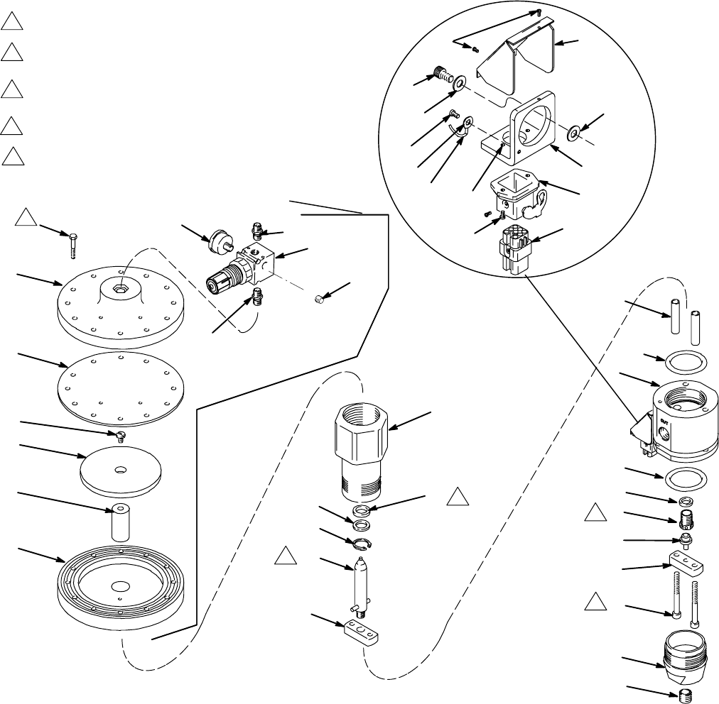
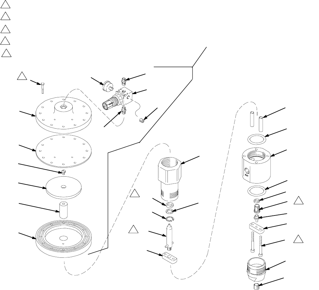
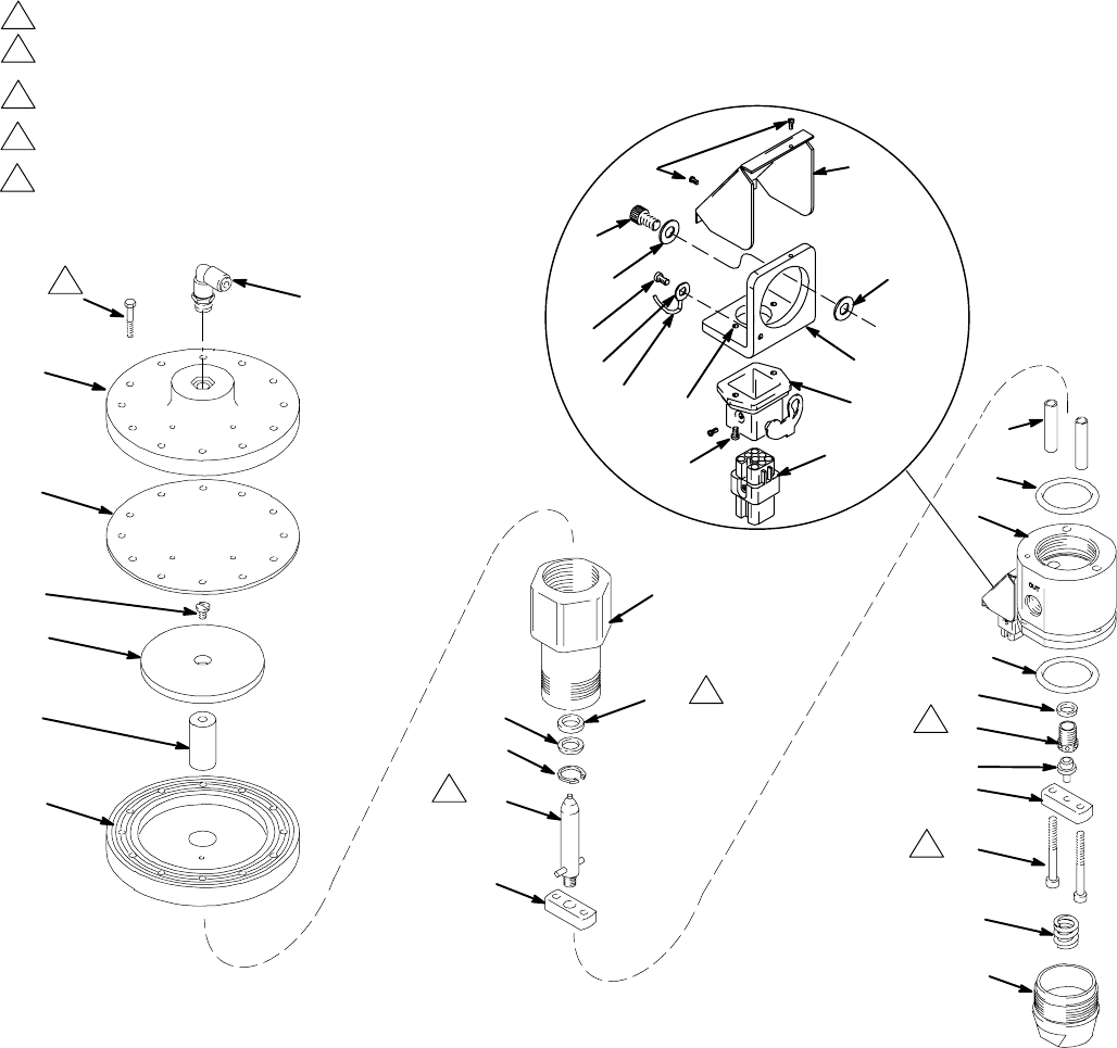
Parts
Model 243700 240 Volt Heated Regulator
111
103
104
114
102
113
101
108
105
107
115
8
10
*13 12
7
15
*4
6
*4
14
5
3
2
16
1
Ref. No. 9 Conversion Kit 915587
1
3
2
1
2
Torque to 35–40 ft-lb (47–54 NSm)
Use LoctiteR TL–242 on threads
Use LoctiteR 601 on threads.
Torque to 15–25 ft-lb (20–34 NSm)
*11
20
TI0342
106
24, 25
21
28
29
26 31
32
30
23
3
4Lips must face retaining ring (11)
4
35 44
38
39
Torque to 170–190 in–lb (19–21 NSm)
in alternating pattern.
5
5
11307517
Parts
Model 243700 230 Volt Heated Regulator
Ref
No. Part No. Description Qty.
1 607499 CAP, end 1
2 607498 BAR, support bottom 1
3 904029 BALL, seat 1
4* 115938 PACKING, o-ring; fluoroelastomer 2
5 904030 SEAT, regulator 1
6 617434 HOUSING, regulator 1
7 607497 SUPPORT, piston 1
8 607500 CYLINDER, valve 1
9 915587 HOUSING, diaphragm
(See separate parts list) 1
10 220899 PISTON, regulator 1
11* 102386 RING, retaining 1
12* 115939 SEAL, mastic reg. fluoroelastomer 1
13* 607495 WASHER 1
14 607718 WASHER, seal 1
15 607496 SPACER 2
16 503143 SCREW, socket head;
5/16–18 x 2.75 in. 2
20 102726 PLUG, pipe, 3/4 in. npt 1
21 100171 SCREW, machine pnh 2
23 115861 BULKHEAD, housing 1
24 115860 INSERT, male 1
25 115862 CONNECTOR, male 5
26 C19269 SCREW, machine, slotted 2
28 C19197 WASHER, plain 2
29 C19800 SCREW, cap, socket hd 2
30 C34043 BRACKET 1
31 C34040 COVER 1
32 C19721 WASHER 1
33 C32255 SENSOR, temperature
See page 31 electrical diagram 1
34 198600 CARTRIDGE, heater
See page 31 electrical diagram 2
35 065345 WIRE, copper electrical (16AWG);
0.5 ft (0.15 m)
See page 31 electrical diagram 1
38 101674 TERMINAL, ring
See page 31 electrical diagram 1
39 112144 SCREW, mach pan hd
See page 31 electrical diagram 1
44 102974 NUT, hex 2
Diaphragm Housing / Conversion Kit 915587
Includes items 101–115
Ref
No. Part No. Description Qty.
101 15U747 HOUSING, diaphragm 1
102 180978 WASHER, support 1
103 15U746 COVER, diaphragm 1
104 180979 DIAPHRAGM 1
105 108190 GAUGE, air pressure; 0–100 psi
(0–0.7 MPa, 0–7 bar) range 1
106 100403 PLUG, pipe; 1/8–27 npt(f) 1
107 110341 REGULATOR, air, relieving;
see manual 308167 1
108 103656 NIPPLE, pipe, hex; 1/8–27 npt 1
111 120730 CAPSCREW, hex washer hd;
1/4–20 x 1.5 12
113 180975 ROD, piston 1
114 103263 SCREW, mach; 1/4–20 x 3/4 in. 1
115 151519 NIPPLE, 1/4 x 1/8 npt 1
* Included in Repair Kit 233131.
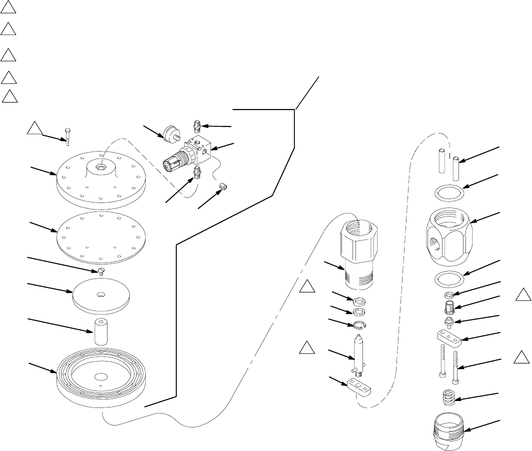
12 307517
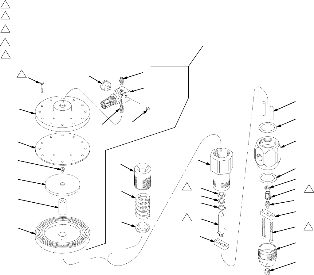
Parts
Model 903958, Series B
Spring-Operated Regulator
Includes items 1–21
Model 961635, Series C
Air-Operated Regulator
Includes items 1–5, 7, 8, 13–22
7241B
OR
OR
111
103
104
114
102
113
101
106
108
105
107
115
6
9
11
7
*19
*3
15
16
18
8*
13
8*
1
20
21
17
2
14
4
Ref. No. 6, 9, 11
Regulator 903958 only
Ref. No. 22 Conversion Kit 915587
Regulator 961635 only
1
3
2
1
3
2
Torque to 35–40 ft-lb (47–54 NSm)
Use LoctiteR TL–242 on threads
Use LoctiteR 601 on threads.
Torque to 15–25 ft-lb (20–34 NSm)
*5
4Lips must face retaining ring (3)
4
Torque to 170–190 in–lb (19–21 NSm)
in alternating pattern.
5
5
13307517
Parts
Model 903958, Series B
Spring-Operated Regulator
Includes items 1–21
Model 961635, Series C
Air-Operated Regulator
Includes items 1–5, 7, 8, 13–22
Ref
No. Part No. Description Qty.
1 607718 WASHER, seal 1
2 503143 SCREW, socket head;
5/16–18 x 2.75 in. 2
3* 102386 RING, retaining 1
4 102726 PLUG, pipe, 3/4 in. npt 1
5* 503140 SEAL, mastic reg., urethane 1
6 607501 SCREW, adjusting;
Model 903958 only 1
7 607500 CYLINDER, valve 1
8* 162841 PACKING, o-ring; buna-N 2
9† 503141 SPRING, high range;
Model 903958 only 1
11 607493 GUIDE, spring;
Model 903958 only 1
13 607502 HOUSING, regulator 1
14 607499 CAP, end 1
15 220899 PISTON, regulator 1
16 607497 BAR, support top 1
17 607498 BAR, support bottom 1
18 607496 SPACER 2
19* 607495 WASHER 1
20 904030 SEAT, regulator;
0.312 in. (8 mm) dia. 1
21 904029 BALL, seat 1
22 915587 HOUSING, diaphragm;
Model 961635 only
(See separate parts list) 1
Diaphragm Housing / Conversion Kit 915587
Includes items 101–115
Ref
No. Part No. Description Qty.
101 15U747 HOUSING, diaphragm 1
102 180978 WASHER, support 1
103 15U746 COVER, diaphragm 1
104 180979 DIAPHRAGM 1
105 108190 GAUGE, air pressure; 0–100 psi
(0–0.7 MPa, 0–7 bar) range 1
106 100403 PLUG, pipe; 1/8–27 npt(f) 1
107 110341 REGULATOR, air, relieving;
see manual 308167 1
108 103656 NIPPLE, pipe, hex; 1/8–27 npt 1
111 120730 CAPSCREW, hex washer hd;
1/4–20 x 1.5 12
113 180975 ROD, piston 1
114 103263 SCREW, mach; 1/4–20 x 3/4 in. 1
115 151519 NIPPLE, 1/4 x 1/8 npt 1
* Included in Repair Kit 918448.
† 521079 Low Range Spring is available. See page 33.
14 307517
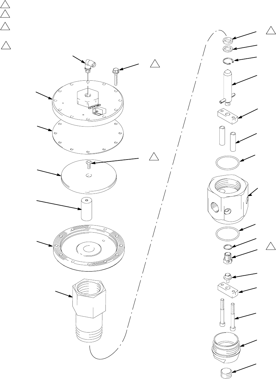
Parts
Model 244740, Series A
Air-Operated Regulator
Includes items 1–37
TI1463A
27
28
26
31
9
8
34
32
29
15
6
36*
14
5
3
2
16
1
22
1
3
2
36*
7
10
11*
12*
13*
1
Torque to 30–40 ft-lb (41–54 NSm)
2
Torque to 75–80 in-lb (8.5–9 NSm)
3
4Lips must face retaining ring (11)
4
Torque to 170–190 in–lb (19–21 NSm)
in alternating pattern.
15307517
Parts
Model 244740, Series A
Air-Operated Regulator
Includes items 1–37
Ref
No. Part No. Description Qty.
1 607499 CAP, end 1
2 607498 BAR, support bottom 1
3 904029 BALL, seat 1
5 904030 SEAT, regulator;
0.312 in. (8 mm) dia. 1
6 198007 HOUSING, regulator 1
7 607497 BAR, support top 1
8 607500 CYLINDER, valve 1
9 15U747 HOUSING, diaphragm 1
10 220899 PISTON, regulator 1
11* 102386 RING, retaining 1
12* 607495 WASHER 1
13* 503140 SEAL, mastic reg., urethane 1
14 607718 WASHER, seal 1
15 607496 SPACER 2
Ref
No. Part No. Description Qty.
16 503143 SCREW, socket head;
5/16–18 x 2.75 in. 2
22 102726 PLUG, pipe, 3/4 in. npt 1
26 180978 WASHER, support 1
27 15U746 COVER, diaphragm 1
28 180979 DIAPHRAGM 1
29 120730 CAPSCREW, hex washer head;
1/4–20 x 1.5 12
31 180975 ROD, piston 1
32 103263 SCREW, machine; 1/4–20 x 3/4 in.1
34 198171 ELBOW 1
35 198241 PLUG, port, pressure
(not shown) 4
36* 162841 PACKING, o–ring 2
37 111457 PACKING, o–ring, pressure port
(not shown) 4
* Included in Repair Kit 918448.
16 307517
Parts
Model C58318
Stainless Steel, Air Operated Regulator
7241B
111
103
104
114
102
113
101
108
105
107
115
20
17
16
19
15
11
14
13
14
12
10
9
8
7
6
1
Ref. No. 3 Conversion Kit 915587
1
3
2
1
3
2
Torque to 35–40 ft-lb (47–54 NSm)
Use LoctiteR TL–242 on threads
Use LoctiteR 601 on threads.
Torque to 15–25 ft-lb (20–34 NSm)
4
21
18
4Lips must face retaining ring (16)
4
Torque to 170–190 in–lb (19–21 NSm)
in alternating pattern.
5
5
17307517
Parts
Model C58318
Stainless Steel, Air Operated Regulator
Ref
No. Part No. Description Qty.
1 111384 PLUG, pipe 1
3 915587 HOUSING, diaphragm
(See separate parts list) 1
4 C06234 VALVE, flow control 1
6 607499 CAP, end 1
7 C55143 SCREW, cap, socket head 2
8 C55136 SUPPORT, piston, bottom 1
9 C55140 STEM, valve assy 1
10 C55139 SEAT, regulator, assy 1
11 C55137 SPACER 2
12 C55133 WASHER, seal 1
13 C55134 HOUSING, regulator 1
14 C38296 PACKING, o-ring 2
15 C55135 SUPPORT, piston, top 1
16 C20385 RING, retaining, internal 1
17 C58314 SUPPORT, seal 1
18 515716 PACKING, u-cup 1
19 C55141 PISTON, regulator 1
20 C58312 CYLINDER, regulator 1
21 C55142 PIN, str, spring 1
Diaphragm Housing / Conversion Kit 915587
Includes items 101–115
Ref
No. Part No. Description Qty.
101 15U747 HOUSING, diaphragm 1
102 180978 WASHER, support 1
103 15U746 COVER, diaphragm 1
104 180979 DIAPHRAGM 1
105 108190 GAUGE, air pressure; 0–100 psi
(0–0.7 MPa, 0–7 bar) range 1
106 100403 PLUG, pipe; 1/8–27 npt(f)
(not shown) 1
107 110341 REGULATOR, air, relieving;
see manual 308167 1
108 103656 NIPPLE, pipe, hex; 1/8–27 npt 1
111 120730 CAPSCREW, hex washer hd;
1/4–20 x 1.5 12
113 180975 ROD, piston 1
114 103263 SCREW, mach; 1/4–20 x 3/4 in. 1
115 151519 NIPPLE, 1/4 x 1/8 npt 1
18 307517
Parts
Model C07720 Water Conditioned Regulator
Includes items 1–20
111
103
104
114
102
113
101
108
105
107
115
8
10
12*
7
15
4*
6
4*
14
5
3
2
16
1
Ref. No. 9 Conversion Kit 915587
1
3
2
1
3
2
Torque to 35–40 ft-lb (47–54 NSm)
Use LoctiteR TL–242 on threads
Use LoctiteR 601 on threads.
Torque to 15–25 ft-lb (20–34 NSm)
TI0344
*11
20
*13
4Lips must face retaining ring (11)
4
106
Torque to 170–190 in–lb (19–21 NSm)
in alternating pattern.
5
5
19307517
Parts
Model C07720 Water Conditioned Regulator
Includes items 1–20
Ref
No. Part No. Description Qty.
1 607499 CAP, end 1
2 607498 BAR, support bottom 1
3 904029 BALL, seat 1
4* 162841 PACKING, o-ring; buna-N 2
5 904030 SEAT, regulator 1
6 C07719 HOUSING, regulator 1
7 607497 SUPPORT, piston 1
8 607500 CYLINDER, valve 1
9 915587 HOUSING, diaphragm
(See separate parts list) 1
10 220899 PISTON, regulator 1
11* 102386 RING, retaining 1
12* 607495 WASHER 1
13* 503140 SEAL, mastic reg., urethane 1
14 607718 WASHER, seal 1
15 607496 SPACER 2
16 503143 SCREW, socket head;
5/16–18 x 2.75 in. 2
20 102726 PLUG, pipe, 3/4 in. npt 1
Diaphragm Housing / Conversion Kit 915587
Includes items 101–115
Ref
No. Part No. Description Qty.
101 15U747 HOUSING, diaphragm 1
102 180978 WASHER, support 1
103 15U746 COVER, diaphragm 1
104 180979 DIAPHRAGM 1
105 108190 GAUGE, air pressure; 0–100 psi
(0–0.7 MPa, 0–7 bar) range 1
106 100403 PLUG, pipe; 1/8–27 npt(f) 1
107 110341 REGULATOR, air, relieving;
see manual 308167 1
108 103656 NIPPLE, pipe, hex; 1/8–27 npt 1
111 120730 CAPSCREW, hex washer hd;
1/4–20 x 1.5 12
113 180975 ROD, piston 1
114 103263 SCREW, mach; 1/4–20 x 3/4 in. 1
115 151519 NIPPLE, 1/4 x 1/8 npt 1
* Included in Repair Kit 918448.
20 307517
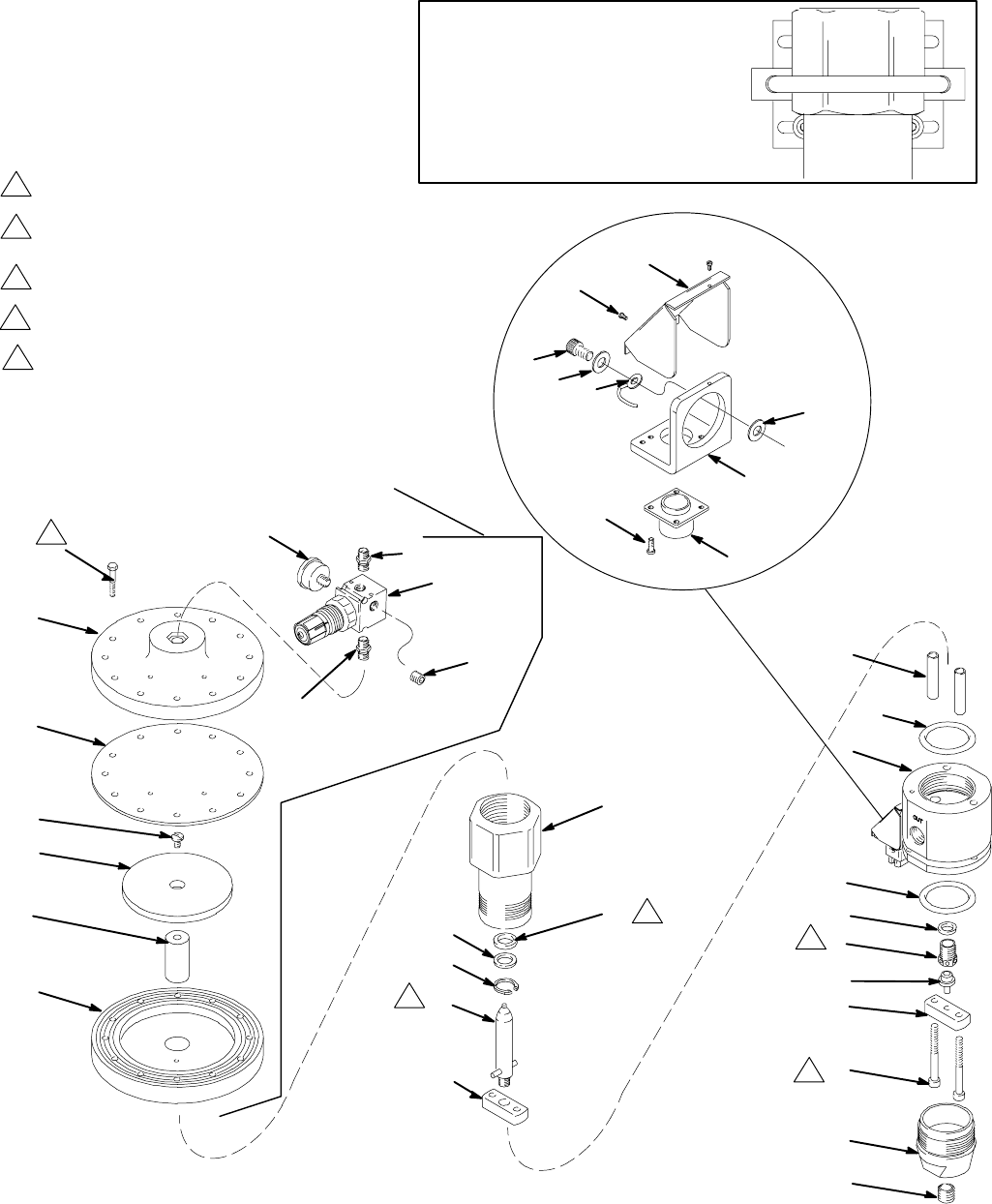
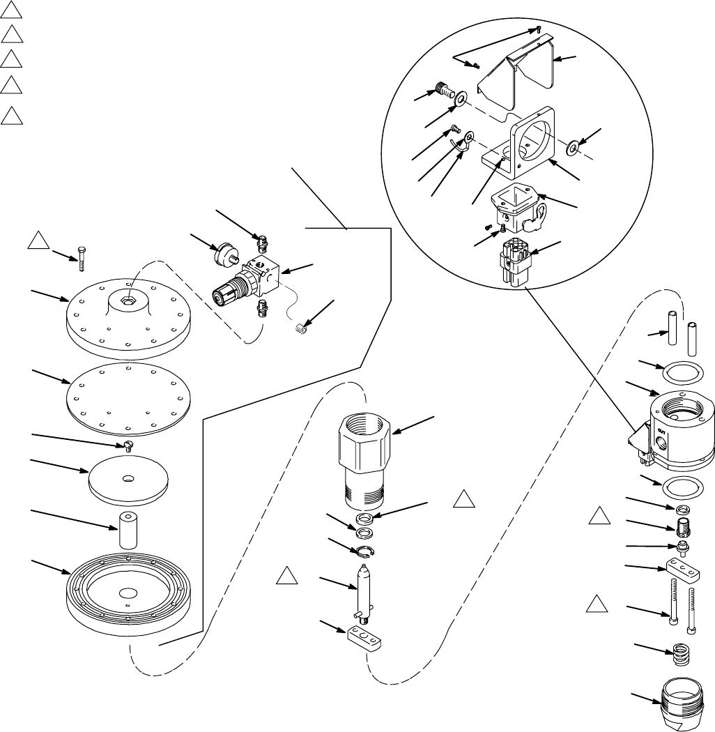
Parts
Model 918447 Heated Regulator
111
103
104
114
102
113
101
108
105
107
115
8
10
*12 13*
7
15
*4
6
*4
14
5
3
2
16
1
Ref. No. 9 Conversion Kit 915587
1
3
2
1
2
Torque to 35–40 ft-lb (47–54 NSm)
Use LoctiteR TL–242 on threads
Use LoctiteR 601 on threads.
Torque to 15–25 ft-lb (20–34 NSm)
*11
20
TI0560
31
26
2928 27
24
23
30
32
3
4Lips must face retaining ring (11)
4
106
Mounting Bracket Kit 247157
Available for Model 918447 only.
Purchase separately.
See page 33.
Torque to 170–190 in–lb (19–21 NSm)
in alternating pattern.
5
5
21307517
Parts
Model 918447 Heated Regulator
Ref
No. Part No. Description Qty.
1 607499 CAP, end 1
2 607498 BAR, support 1
3 904029 BALL, seat 1
4* 115938 PACKING, o–ring 2
5 904030 SEAT, regulator 1
6 617434 HOUSING, heated, regulator 1
7 607497 SUPPORT, piston 1
8 607500 CYLINDER, valve 1
9 915587 HOUSING, diaphragm
(See separate parts list) 1
10 220899 PISTON, regulator 1
11* 102386 RING, retaining 1
12* 607495 WASHER 1
13* 115939 SEAL, rod, .750 ID, fluoroelastomer
1
14 607718 WASHER, seal 1
15 607496 SPACER 2
16 503143 SCREW, cap, sch 2
20 102726 PLUG, pipe, headless 1
23 C07329 CONNECTOR, 6–pin gun 1
24 C19950 SCREW, cap, sch 4
25 102794 NUT, hex 4
26 C19269 SCREW, mach, slotted hd 2
27 C50019 TERMINAL, ring 1
28 C19197 WASHER, plain 2
29 C19800 SCREW, cap, socket hd 2
30 C34043 BRACKET 1
31 C34040 COVER 1
32 C19721 WASHER 1
33 C32255 SENSOR, temperature
See page 31 electrical diagram 1
34 C31034 HEATER, cartridge
See page 31 electrical diagram 2
Diaphragm Housing / Conversion Kit 915587
Includes items 101–115
Ref
No. Part No. Description Qty.
101 15U747 HOUSING, diaphragm 1
102 180978 WASHER, support 1
103 15U746 COVER, diaphragm 1
104 180979 DIAPHRAGM 1
105 108190 GAUGE, air pressure; 0–100 psi
(0–0.7 MPa, 0–7 bar) range 1
106 100403 PLUG, pipe; 1/8–27 npt(f) 1
107 110341 REGULATOR, air, relieving;
see manual 308167 1
108 103656 NIPPLE, pipe, hex; 1/8–27 npt 1
111 120730 CAPSCREW, hex washer hd;
1/4–20 x 1.5 12
113 180975 ROD, piston 1
114 103263 SCREW, mach; 1/4–20 x 3/4 in. 1
115 151519 NIPPLE, 1/4 x 1/8 npt 1
* Included in Repair Kit 233131.
22 307517
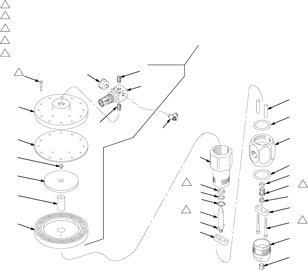
Parts
Model 246642, Series A
Air-Operated Regulator
Includes items 1–37
1
3
2
Torque to 30–40 ft-lb (41–54 NSm)
Torque to 75–80 in-lb (8.5–9 NSm)
Torque to 170–190 in-lb (19–21 NSm) in an
alternating pattern.
4Lips must face retaining ring (11)
27
28
26
31
9
8
34
32
29
15
6
36†*
14
5
3
2
16
1†
22†
36*
7
10
11*
12*
13*
1
2
34
23307517
Parts
Model 246642, Series A
Air-Operated Regulator
Includes items 1–37
Ref
No. Part No. Description Qty.
1† 15C280 CAP, end 1
2 607498 BAR, support bottom 1
3 904029 BALL, seat 1
5 904030 SEAT, regulator;
0.312 in. (8 mm) dia. 1
6 198007 HOUSING, regulator 1
7 607497 BAR, support top 1
8 607500 CYLINDER, valve 1
9 15U747 HOUSING, diaphragm 1
10 220899 PISTON, regulator 1
11* 102386 RING, retaining 1
12* 607495 WASHER 1
13* 503140 SEAL, mastic reg., urethane 1
14 607718 WASHER, seal 1
15 607496 SPACER 2
Ref
No. Part No. Description Qty.
16 503143 SCREW, socket head;
5/16–18 x 2.75 in. 2
22† 15C281 SPRING, compression 1
26 180978 WASHER, support 1
27 15U746 COVER, diaphragm 1
28 180979 DIAPHRAGM 1
29 120730 CAPSCREW, hex washer head;
1/4–20 x 1.5 12
31 180975 ROD, piston 1
32 103263 SCREW, machine; 1/4–20 x 3/4 in.1
34 198171 ELBOW 1
35 198241 PLUG, port, pressure
(not shown) 4
36†* 162841 PACKING, o–ring 2
37 111457 PACKING, o–ring, pressure port
(not shown) 4
* Included in Repair Kit 918448.
† Included in Repair Kit 246728.
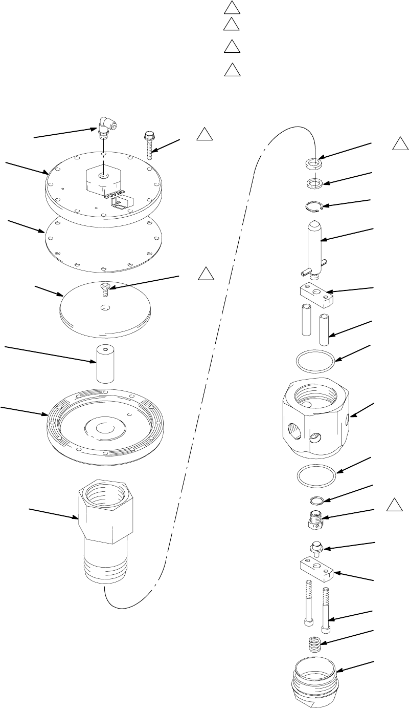
24 307517
Parts
Model 246687 and 262549, Series A
Air-Operated Regulator
7241B
111
103
104
114
102
113
101
106
108
105
107
115
7
*19
*3
15
16
18
8*
13
8*†
1
20
21
17
2
14†
4†
Ref. No. 22 Conversion Kit 915587
1
3
2
1
3
2
Torque to 35–40 ft-lb (47–54 NSm)
Use LoctiteR TL–242 on threads
Use LoctiteR 601 on threads.
Torque to 15–25 ft-lb (20–34 NSm)
*5
4Lips must face retaining ring (3)
4
Torque to 170–190 in–lb (19–21 NSm)
in alternating pattern.
5
5
25307517
Parts
Model 246687 and 262549, Series A
Air-Operated Regulator
Ref
No. Part No. Description Qty.
1 607718 WASHER, seal 1
2 503143 SCREW, socket head;
5/16–18 x 2.75 in. 2
3* 102386 RING, retaining 1
4† 15C281 SPRING, compression 1
5* 503140 SEAL, mastic reg., urethane 1
7 607500 CYLINDER, valve 1
8*† 162841 PACKING, o-ring; buna-N 2
13 607502 HOUSING, regulator 1
14† 15C280 CAP, end 1
15 220899 PISTON, regulator 1
16 607497 BAR, support top 1
17 607498 BAR, support bottom 1
18 607496 SPACER 2
19* 607495 WASHER 1
20 904030 SEAT, regulator;
0.312 in. (8 mm) dia. 1
21 904029 BALL, seat 1
22 915587 HOUSING, diaphragm
(See parts list at right) 1
Diaphragm Housing / Conversion Kit 915587
Ref
No. Part No. Description Qty.
101 15U747 HOUSING, diaphragm 1
102 180978 WASHER, support 1
103 15U746 COVER, diaphragm 1
104 180979 DIAPHRAGM 1
105 108190 GAUGE, air pressure; 0–100 psi
(0–0.7 MPa, 0–7 bar) range 1
106 100403 PLUG, pipe; 1/8–27 npt(f) 1
107 110341 REGULATOR, air, relieving; model
246687 only, see manual 308167 1
16G409 REGULATOR, air, relieving; model
262549 only, see manual 308167 1
108 103656 NIPPLE, pipe, hex; 1/8–27 npt 1
111 120730 CAPSCREW, hex washer hd;
1/4–20 x 1.5 12
113 180975 ROD, piston 1
114 103263 SCREW, mach; 1/4–20 x 3/4 in. 1
115 151519 NIPPLE, 1/4 x 1/8 npt 1
* Included in Repair Kit 918448.
† Included in Repair Kit 246728.
26 307517
Parts
Model 246643, 240 Volt Heated Regulator
111
103
104
114
102
113
101
105
8
10
*13 12*
7
15
*4
6
†*4
14
5
3
2
16
1†
1
3
2
1
2
Torque to 35–40 ft-lb (47–54 NSm)
Use LoctiteR TL–242 on threads
Use LoctiteR 601 on threads.
Torque to 15–25 ft-lb (20–34 NSm)
*11
†20
TI0342 rev
4Lips must face retaining ring (11)
4
3
24, 25
21
28
29
26 31
32
30
23
35 44
38
39
Torque to 170–190 in–lb (19–21 NSm) in alternating
pattern.
5
5
27307517
Parts
Model 246643, 240 Volt Heated Regulator
Ref
No. Part No. Description Qty.
1† 15C280 CAP, end 1
2 607498 BAR, support bottom 1
3 904029 BALL, seat 1
4*† 115938 PACKING, o-ring; fluoroelastomer 2
5 904030 SEAT, regulator 1
6 617434 HOUSING, regulator 1
7 607497 SUPPORT, piston 1
8 607500 CYLINDER, valve 1
10 220899 PISTON, regulator 1
11* 102386 RING, retaining 1
12* 115939 SEAL, mastic reg. fluoroelastomer 1
13* 607495 WASHER 1
14 607718 WASHER, seal 1
15 607496 SPACER 2
16 503143 SCREW, socket head;
5/16–18 x 2.75 in. 2
20† 15C281 SPRING, compression 1
21 100171 SCREW, machine pnh 2
23 115861 BULKHEAD, housing 1
24 115860 INSERT, male 1
25 115862 CONNECTOR, male 5
26 C19269 SCREW, machine, slotted 2
28 C19197 WASHER, plain 2
29 C19800 SCREW, cap, socket hd 2
30 C34043 BRACKET 1
31 C34040 COVER 1
32 C19721 WASHER 1
33 C32255 SENSOR, temperature
See page 31 electrical diagram 1
34 198600 CARTRIDGE, heater
See page 31 electrical diagram 2
35 065345 WIRE, copper electrical (16AWG);
0.5 ft (0.15 m)
See page 31 electrical diagram 1
38 101674 TERMINAL, ring
See page 31 electrical diagram 1
39 112144 SCREW, mach pan hd
See page 31 electrical diagram 1
44 102974 NUT, hex 2
Ref
No. Part No. Description Qty.
101 15U747 HOUSING, diaphragm 1
102 180978 WASHER, support 1
103 15U746 COVER, diaphragm 1
104 180979 DIAPHRAGM 1
105 198171 ELBOW 1
111 120730 CAPSCREW, hex washer hd;
1/4–20 x 1.5 12
113 180975 ROD, piston 1
114 103263 SCREW, mach; 1/4–20 x 3/4 in. 1
* Included in Repair Kit 233131.
† Included in Repair Kit 246728.
28 307517
Parts
Model 246688, 240 Volt Heated Regulator
111
103
104
114
102
113
101
108
105
107
115
8
10
*13 12*
7
15
6
†*4
14
5
3
2
16
1†
Ref. No. 9 Conversion Kit 915587
1
3
2
2
Torque to 35–40 ft-lb (47–54 NSm)
Use LoctiteR TL–242 on threads
Use LoctiteR 601 on threads.
Torque to 15–25 ft-lb (20–34 NSm)
*11
†20
106
TI0342B
4Lips must face retaining ring (11)
4
3
1
*4
24, 25
21
28
29
26 31
32
30
23
35 44
38
39
Torque to 170–190 in–lb (19–21 NSm) in alternating
pattern.
5
5
29307517
Parts
Model 246688, 240 Volt Heated Regulator
Ref
No. Part No. Description Qty.
1† 15C280 CAP, end 1
2 607498 BAR, support bottom 1
3 904029 BALL, seat 1
4*† 115938 PACKING, o-ring; fluoroelastomer 2
5 904030 SEAT, regulator 1
6 617434 HOUSING, regulator 1
7 607497 SUPPORT, piston 1
8 607500 CYLINDER, valve 1
9 915587 HOUSING, diaphragm
(See separate parts list) 1
10 220899 PISTON, regulator 1
11* 102386 RING, retaining 1
12* 115939 SEAL, mastic reg. fluoroelastomer 1
13* 607495 WASHER 1
14 607718 WASHER, seal 1
15 607496 SPACER 2
16 503143 SCREW, socket head;
5/16–18 x 2.75 in. 2
20† 15C281 SPRING, compression 1
21 100171 SCREW, machine pnh 2
23 115861 BULKHEAD, housing 1
24 115860 INSERT, male 1
25 115862 CONNECTOR, male 5
26 C19269 SCREW, machine, slotted 2
28 C19197 WASHER, plain 2
29 C19800 SCREW, cap, socket hd 2
30 C34043 BRACKET 1
31 C34040 COVER 1
32 C19721 WASHER 1
33 C32255 SENSOR, temperature
See page 31 electrical diagram 1
34 198600 CARTRIDGE, heater
See page 31 electrical diagram 2
35 065345 WIRE, copper electrical (16AWG);
0.5 ft (0.15 m)
See page 31 electrical diagram 1
38 101674 TERMINAL, ring
See page 31 electrical diagram 1
39 112144 SCREW, mach pan hd
See page 31 electrical diagram 1
44 102974 NUT, hex 2
Diaphragm Housing / Conversion Kit 915587
Includes items 101–115
Ref
No. Part No. Description Qty.
101 15U747 HOUSING, diaphragm 1
102 180978 WASHER, support 1
103 15U746 COVER, diaphragm 1
104 180979 DIAPHRAGM 1
105 108190 GAUGE, air pressure; 0–100 psi
(0–0.7 MPa, 0–7 bar) range 1
106 100403 PLUG, pipe; 1/8–27 npt(f) 1
107 110341 REGULATOR, air, relieving;
see manual 308167 1
108 103656 NIPPLE, pipe, hex; 1/8–27 npt 1
111 120730 CAPSCREW, hex washer hd;
1/4–20 x 1.5 12
113 180975 ROD, piston 1
114 103263 SCREW, mach; 1/4–20 x 3/4 in. 1
115 151519 NIPPLE, 1/4 x 1/8 npt 1
* Included in Repair Kit 233131.
† Included in Repair Kit 246728.
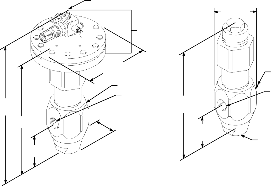
30 307517
Dimensions
7243B
3/4 npt(f)
OUTLET
3/4 npt(f)
INLET
OPTIONAL
3/4 npt(f)
OUTLET
12 in.
(305 mm)
2.63 in.
(67 mm)
3.25 in.
(82.5 mm)
Model 903958 and C58318
Models 961635, C58318, 243700,
C59584, 244740, 246642, 246643, 246687,
and 246688.
1/4 npt(m)
AIR CONNECTION
CONVERSION
KIT 915587
6.8 in.
(173 mm)
3/4 npt(f)
OUTLET
3/4 npt(f)
SIDE INLET
2.75 in.
(70 mm)
2.63 in.
(67 mm)
10.5 in.
(267 mm)
13.5 in.
(343 mm)
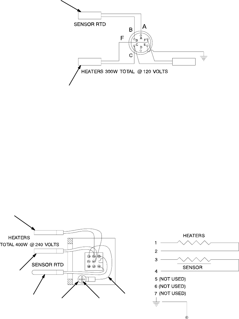
31307517
Wiring Diagram
These regulators are controlled by Graco Therm–O–Flow controls.
{33
}34
TI0504
120 Volt Models 918447
NOTE: Allow sufficient lead wire length to be able to rotate connector bracket +/–180°
{ 108.2 Ω (+/– 1.1 Ω @ 70°F)
} 96 Ω (+9.6 Ω /−14.4 @ Ω each)
Resistance measurements across pins C and F = 40.8 – 52.8 Ω
____________________________________________________________________________________________
This regulator is controlled by Graco Therm–O–Flow Plus controls.
240 Volt Model 243700, 246643, and 246688
35
39
38
{33
K34
TI0504
K34
{ 108.2 Ω (+/– 1.1 Ω @ 70°F)
K 288 Ω (+28.8 Ω /−14.4 @ Ω each)
Resistance measurements across
p
ins 1 and 2 = 136.8 – 158.4 Ω
WIRING DIAGRAM SCHEMATIC DIAGRAM

32 307517
Technical Data
Category Data
Regulated Fluid Pressure Range Models 961635, C58318, and 244740
250–4500 psi (1.7–31.0 MPa, 17–310 bar)
Models 243700 and 918447
250–3500 psi (1.7–24.1 MPa, 17–241 bar)
Model 903958
High Range: 1000–4500 psi (7.0–31.0 MPa, 70–310 bar)
Low Range: 400–1000 psi (2.8–7.0 MPa, 28–70 bar)
Models 246642 and 246687
100–4500 psi (0.7–31.0 MPa, 7–310 bar)
Model 246643 and 246688
100–3500 psi (0.7–24.1 MPa, 7–241 bar)
Maximum Fluid Inlet Pressure 5000 psi (34.4 MPa, 344 bar)
Maximum Fluid Temperatures
Ambient or conditioned
Heated 140°F (60°C)
400°F (202°C)
Pressure Drop (Measured at 400 psi inlet
pressure and 1.5 gpm) Viscosity of 25,000 CPS: 100 psid
Viscosity of 80,000 CPS: 375 psid
Wetted Parts 903958, 961635, 244740,
246642, and 246687 zinc-plated carbon steel, brass, stainless steel, Buna-N, urethane,
tungsten carbide
Wetted Parts 243700, 918447, 246643, and
246688 zinc-plated carbon steel, brass, stainless steel, fluoroelastomer,
tungsten carbide
Wetted Parts C58318 303, 304, 316 stainless steel, tungsten carbide, UHMWPE, ethyl-
ene propylene, PTFE
Inlet (one) 3/4 npt(f), at side
Outlets (two) 3/4 npt(f), at side and bottom, at side only on 246642, 246643,
246687, 246688, and 262549.
Weights Air Operated Model 961635: 17.75 lb (7.9 kg)
Spring Operated Model 903958: 13.5 lb (6.1 kg)
LoctiteR is a registered trademark of the Loctite Corporation.
33307517
Accessories
113654 Fluid Pressure Gauge
Maximum pressure: 5000 psi (34 MPa, 340 bar).
1/4 npt(m). Requires bushing (100615).
521079 Low Range Conversion Spring
Replaces the original spring in the 903958 regulator
when 400–1000 psi (2.8–7.0 MPa, 28–70 bar) regu-
lated pressure range is required.
C06234 Bleed Valve (3/8 NPT)
Adjustable air regulator bleed for improved fluid pres-
sure accuracy. Replaces the plug in air regulator outlet
port.
915587 Spring to Air Conversion Kit
Converts an existing 903958 spring-operated regulator
to an air-operated regulator
246728 Spring Loaded Fluid Section Con-
version Kit
Replaces end cap 607499 with 15C280 and adds
spring 15C281. Allows for lower regulated outlet fluid
pressure. The appropriate o–ring must be used for the
correct regulator. O–rings are shipped for all regulator
assemblies. Refer to parts list for your regulator and
install the appropriate o–ring.
247157 Mounting Bracket Kit
Available for Model 918447 only.

34 307517
Graco Standard Warranty
Graco warrants all equipment manufactured by Graco and bearing its name to be free from defects in material and workmanship on the
date of sale to the original purchaser for use. With the exception of any special, extended, or limited warranty published by Graco,
Graco will, for a period of twelve months from the date of sale, repair or replace any part of the equipment determined by Graco to be
defective. This warranty applies only when the equipment is installed, operated and maintained in accordance with Graco’s written
recommendations.
This warranty does not cover, and Graco shall not be liable for general wear and tear, or any malfunction, damage or wear caused by
faulty installation, misapplication, abrasion, corrosion, inadequate or improper maintenance, negligence, accident, tampering, or sub-
stitution of non–Graco component parts. Nor shall Graco be liable for malfunction, damage or wear caused by the incompatibility of
Graco equipment with structures, accessories, equipment or materials not supplied by Graco, or the improper design, manufacture,
installation, operation or maintenance of structures, accessories, equipment or materials not supplied by Graco.
This warranty is conditioned upon the prepaid return of the equipment claimed to be defective to an authorized Graco distributor for
verification of the claimed defect. If the claimed defect is verified, Graco will repair or replace free of charge any defective parts. The
equipment will be returned to the original purchaser transportation prepaid. If inspection of the equipment does not disclose any defect
in material or workmanship, repairs will be made at a reasonable charge, which charges may include the costs of parts, labor, and
transportation.
THIS WARRANTY IS EXCLUSIVE, AND IS IN LIEU OF ANY OTHER WARRANTIES, EXPRESS OR IMPLIED, INCLUDING BUT
NOT LIMITED TO WARRANTY OF MERCHANTABILITY OR WARRANTY OF FITNESS FOR A PARTICULAR PURPOSE.
Graco’s sole obligation and buyer’s sole remedy for any breach of warranty shall be as set forth above. The buyer agrees that no other
remedy (including, but not limited to, incidental or consequential damages for lost profits, lost sales, injury to person or property, or any
other incidental or consequential loss) shall be available. Any action for breach of warranty must be brought within two (2) years of the
date of sale.
Graco makes no warranty, and disclaims all implied warranties of merchantability and fitness for a particular purpose in connection
with accessories, equipment, materials or components sold but not manufactured by Graco. These items sold, but not manufactured
by Graco (such as electric motors, switches, hose, etc.), are subject to the warranty, if any, of their manufacturer. Graco will provide
purchaser with reasonable assistance in making any claim for breach of these warranties.
In no event will Graco be liable for indirect, incidental, special or consequential damages resulting from Graco supplying equipment
hereunder, or the furnishing, performance, or use of any products or other goods sold hereto, whether due to a breach of contract,
breach of warranty, the negligence of Graco, or otherwise.
FOR GRACO CANADA CUSTOMERS
The parties acknowledge that they have required that the present document, as well as all documents, notices and legal proceedings
entered into, given or instituted pursuant hereto or relating directly or indirectly hereto, be drawn up in English. Les parties reconnais-
sent avoir convenu que la rédaction du présente document sera en Anglais, ainsi que tous documents, avis et procédures judiciaires
exécutés, donnés ou intentés à la suite de ou en rapport, directement ou indirectement, avec les procedures concernées.
Graco Information
For the latest information about Graco products, visit www.graco.com.
TO PLACE AN ORDER, contact your Graco distributor or call to identify the distributor closest to you:
Phone: 612–623–6921 or Toll Free: 1–800–328–0211 Fax: 612–378–3505
All written and visual data contained in this document reflects the latest product information available at the time of publication.
Graco reserves the right to make changes at any time without notice.
Original instructions. This manual contains English. MM 307517
Graco Headquarters: Minneapolis
International Offices: Belgium, China, Japan, Korea
GRACO INC. P.O. BOX 1441 MINNEAPOLIS, MN 55440–1441
Copyright 2001, Graco Inc. is registered to ISO 9001
www.graco.com
Revised 10/2010
