Graco 311283E Gh833 Sprayer Users Manual Sprayer, Repair Manual, English
2015-04-02
: Graco Graco-311283E-Gh833-Sprayer-Users-Manual-686433 graco-311283e-gh833-sprayer-users-manual-686433 graco pdf
Open the PDF directly: View PDF ![]() .
.
Page Count: 36
- Warning
- Component Identification
- Operation
- General Repair Information
- Maintenance
- Troubleshooting
- Compensator Seal Replacement
- Displacement Pump Replacement
- Pump Power Head Replacement
- Hydraulic Motor
- Filter Housing Replacement
- Hydraulic Pump Replacement
- Changing Hydraulic Fluid Filter
- Cooler Replacement
- Motor Replacement
- Removing Handle
- Technical Data
- Notes
- Graco Standard Warranty
311283E
ENG
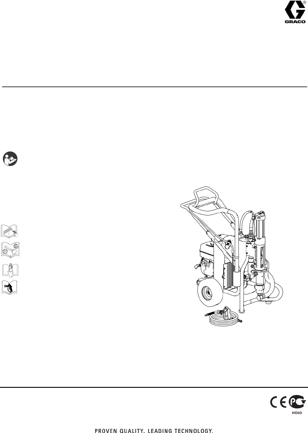
Repair
GH™ 833 Sprayers
For use with Architectural Coatings, Paints, Roof Coatings and Below Grade Coatings. For
professional use only.
Model: 249318, 249617, 253471, 253472
4000 psi (27.6 MPa, 275.8 bar) Maximum Working Pressure
Korean patent: 10-0647761
Related Manuals
IMPORTANT SAFETY INSTRUCTIONS
Read all warnings and instructions in this
manual. Save these instructions.
311279
311484
311485
311254
ti7107b
Warning
2311283E
Warning
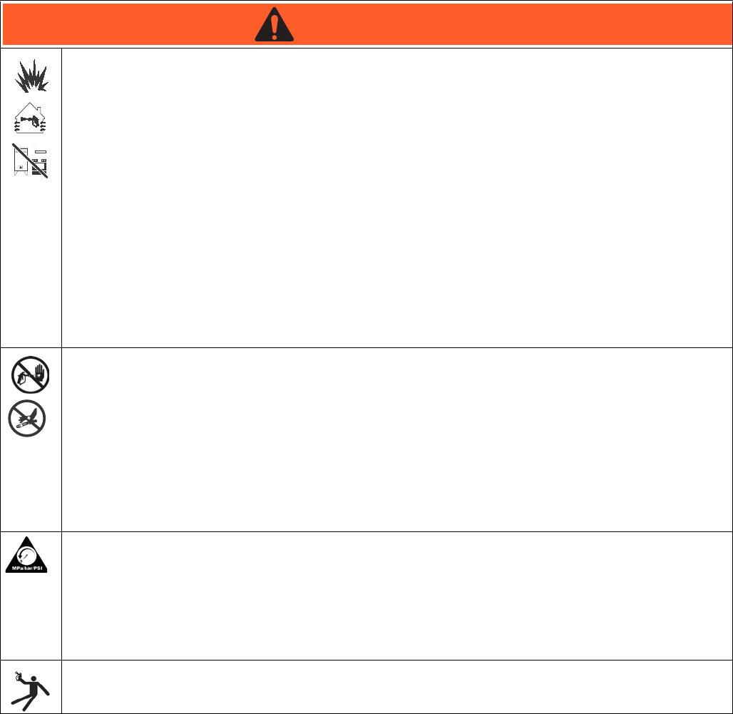
The following warnings are for the setup, use, grounding, maintenance, and repair of this equipment. The exclama-
tion point symbol alerts you to a general warning and the hazard symbols refer to procedure-specific risks. When
these symbols appear in the body of this manual, refer back to these Warnings. Product-specific hazard symbols and
warnings not covered in this section may appear throughout the body of this manual where applicable.
WARNINGWARNINGWARNING
WARNING
FIRE AND EXPLOSION HAZARD
Flammable fumes, such as solvent and paint fumes, in work area can ignite or explode. To help prevent
fire and explosion:
• Use equipment only in well ventilated area.
• Do not fill fuel tank while engine is running or hot; shut off engine and let it cool. Fuel is flammable and
can ignite or explode if spilled on hot surface.
• Eliminate all ignition sources; such as pilot lights, cigarettes, portable electric lamps, and plastic drop
cloths (potential static arc).
• Keep work area free of debris, including solvent, rags and gasoline.
• Do not plug or unplug power cords, or turn power or light switches on or off when flammable fumes are
present.
• Ground all equipment in the work area. See Grounding instructions.
• Use only grounded hoses.
• Hold gun firmly to side of grounded pail when triggering into pail.
• If there is static sparking or you feel a shock, stop operation immediately. Do not use equipment until
you identify and correct the problem.
• Keep a working fire extinguisher in the work area.
SKIN INJECTION HAZARD
High-pressure fluid from gun, hose leaks, or ruptured components will pierce skin. This may look like just a
cut, but it is a serious injury that can result in amputation. Get immediate surgical treatment.
• Do not point gun at anyone or at any part of the body.
• Do not put your hand over the spray tip.
• Do not stop or deflect leaks with your hand, body, glove, or rag.
• Do not spray without tip guard and trigger guard installed.
• Engage trigger lock when not spraying.
• Follow Pressure Relief Procedure in this manual, when you stop spraying and before cleaning,
checking, or servicing equipment.
PRESSURIZED EQUIPMENT HAZARD
Fluid from the gun/dispense valve, leaks, or ruptured components can splash in the eyes or on skin and
cause serious injury.
• Follow Pressure Relief Procedure in this manual, when you stop spraying and before cleaning,
checking, or servicing equipment.
• Tighten all fluid connections before operating the equipment.
• Check hoses, tubes, and couplings daily. Replace worn or damaged parts immediately.
RECOIL HAZARD
Brace yourself; gun may recoil when triggered and cause you to fall, which could cause serious injury.
Warning
311283E 3
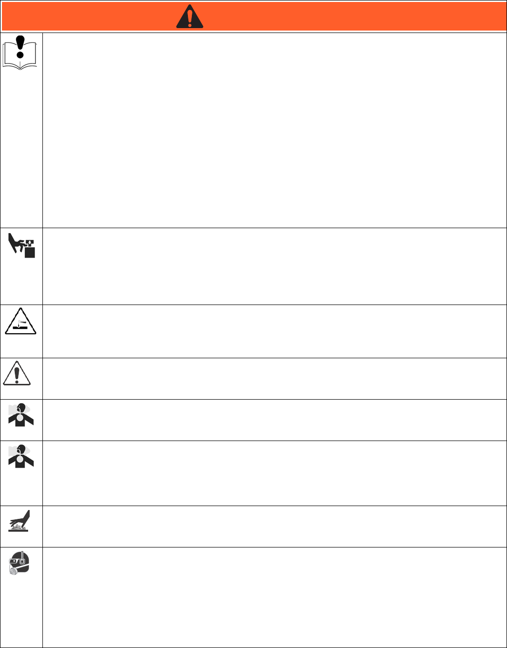
EQUIPMENT MISUSE HAZARD
Misuse can cause death or serious injury.
• Do not operate the unit when fatigued or under the influence of drugs or alcohol.
• Do not exceed the maximum working pressure or temperature rating of the lowest rated system com-
ponent. See Technical Data in all equipment manuals.
• Use fluids and solvents that are compatible with equipment wetted parts. See Technical Data in all
equipment manuals. Read fluid and solvent manufacturer’s warnings. For complete information about
your material, request MSDS forms from distributor or retailer.
• Check equipment daily. Repair or replace worn or damaged parts immediately with genuine Manufac-
turer’s replacement parts only.
• Do not alter or modify equipment.
• Use equipment only for its intended purpose. Call your distributor for information.
• Route hoses and cables away from traffic areas, sharp edges, moving parts, and hot surfaces.
• Do not kink or over bend hoses or use hoses to pull equipment.
• Keep children and animals away from work area.
• Comply with all applicable safety regulations.
MOVING PARTS HAZARD
Moving parts can pinch or amputate fingers and other body parts.
• Keep clear of moving parts.
• Do not operate equipment with protective guards or covers removed.
• Pressurized equipment can start without warning. Before checking, moving, or servicing equipment,
follow the Pressure Relief Procedure in this manual. Disconnect power or air supply.
PRESSURIZED ALUMINUM PARTS HAZARD
Do not use 1,1,1-trichloroethane, methylene chloride, other halogenated hydrocarbon solvents or fluids
containing such solvents in pressurized aluminum equipment. Such use can cause serious chemical reac-
tion and equipment rupture, and result in death, serious injury, and property damage.
SUCTION HAZARD
Never place hands near the pump fluid inlet when pump is operating or pressurized. Powerful suction could
cause serious injury.
CARBON MONOXIDE HAZARD
Exhaust contains poisonous carbon monoxide, which is colorless and odorless. Breathing carbon
monoxide can cause death. Do not operate in an enclosed area.
TOXIC FLUID OR FUMES HAZARD
Toxic fluids or fumes can cause serious injury or death if splashed in the eyes or on skin, inhaled, or swal-
lowed.
• Read MSDS’s to know the specific hazards of the fluids you are using.
• Store hazardous fluid in approved containers, and dispose of it according to applicable guidelines.
BURN HAZARD
Equipment surfaces and fluid that’s heated can become very hot during operation. To avoid severe burns,
do not touch hot fluid or equipment. Wait until equipment/fluid has cooled completely.
PERSONAL PROTECTIVE EQUIPMENT
You must wear appropriate protective equipment when operating, servicing, or when in the operating area
of the equipment to help protect you from serious injury, including eye injury, inhalation of toxic fumes,
burns, and hearing loss. This equipment includes but is not limited to:
• Protective eyewear
• Clothing and respirator as recommended by the fluid and solvent manufacturer
•Gloves
• Hearing protection
WARNINGWARNINGWARNING
WARNING
Component Identification
4311283E
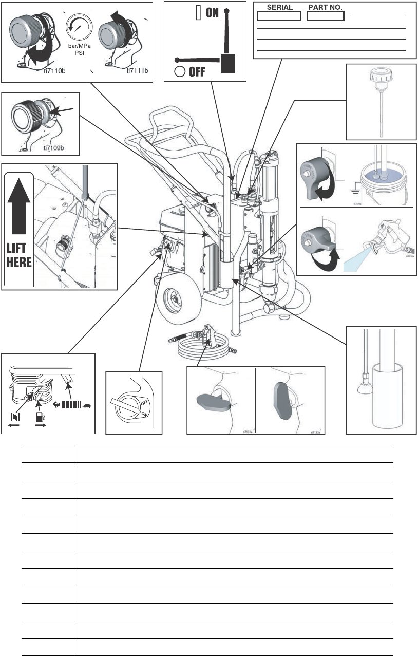
Component Identification
,
ti7133b
ti7107b
3
2
4
1
6
7
5
9
11
10
ti7133
8
Ref Description
1 Hydraulic pump valve
2 Pressure control
3 Lock ring
4 Drain valve
5 Engine ON/OFF switch
6 Engine controls
7 Trigger lock
8 Serial number ID label
9 Lift locations
10 Suction holder
11 Hydraulic oil fill
Operation
311283E 5
Operation
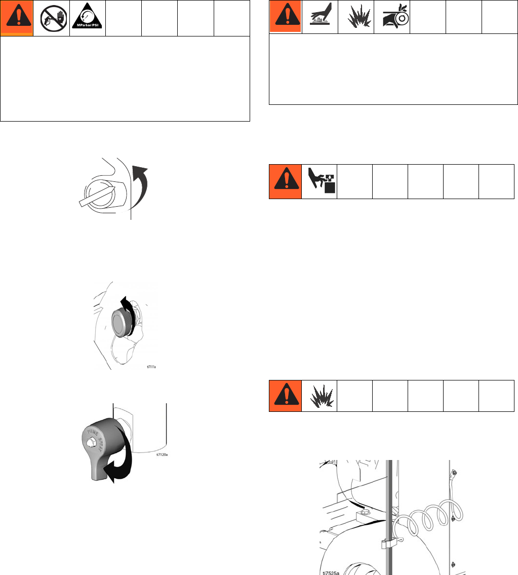
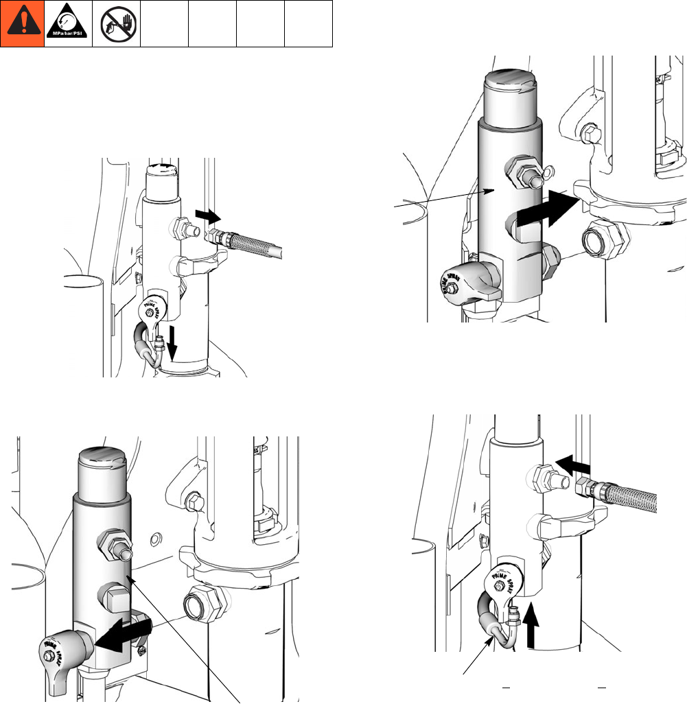
Pressure Relief Procedure
1. Set pump valve OFF. Turn engine OFF.
2. Turn pressure to lowest setting. Trigger gun into pail
to relieve pressure.
3. Open prime valve (vertical).
If you suspect that the spray tip or hose is completely
clogged, or that pressure has not been fully relieved after
following the steps above, VERY SLOWLY, loosen tip
guard retaining nut or hose end coupling to relieve pres-
sure gradually, then loosen completely. Then clean tip
and hose.
General Repair Information
• Install belt guard before operation of sprayer and
replace if damaged. Belt guard reduces risk of
pinching and loss of fingers.
To reduce risk of serious injury,:
• Keep all screws, nuts, washers, etc. removed during
repair procedures. These parts usually are not pro-
vided with replacement kits.
• Test repairs after problems are corrected.
• If sprayer does not operate properly, review repair
procedure to verify you did it correctly. See Trouble-
shooting, page 7.
• Do not touch moving parts with fingers or tools while
testing repair.
Grounding
Ground sprayer with grounding clamp to earth ground
for safe sprayer operation.
System pressure must be manually relieved to prevent
it from starting or spraying accidentally. Fluid under high
pressure can be injected into the skin and cause seri-
ous injury. To reduce risk of injury from injection, follow
this procedure whenever you are instructed to relieve
pressure, stop spraying, service equipment or install or
clean spray tip. Read warnings, page 4.
TIA
• Hydraulic system and engine may become very hot
during operation and could burn skin if touched.
Flammable materials spilled on hot, bare motor
could cause fire or explosion. Have belt guard in
place during operation to reduce risk of pinching or
loss of fingers.
Maintenance
6311283E
Maintenance
For detailed engine maintenance and specifications, re-
fer to separate Honda Engines Owner’s Manual, sup-
plied.
Spark Plug:
• Use BPR6ES (NGK) or W20EPR-U (NIPPON-
DENSO) plug, only.
• Gap plug to 0.028 to 0.031 in. (0.7 to 0.8 mm).
• Use spark plug wrench when installing and remov-
ing plug.
Frequency Procedure
Daily Check engine oil level and fill as necessary.
Daily Check hydraulic oil level and fill as necessary.
Daily Check hose for wear and damage.
Daily Check gun safety for proper operation.
Daily Check pressure drain valve for proper operation.
Daily Check and fill gas tank.
Daily Check that displacement pump is tight.
Daily Check level of TSL in displacement pump packing nut. Fill nut, if neces-
sary. Keep TSL in nut to help prevent fluid build up on piston rod and
premature wear of packings and pump corrosion.
After first 20 hours
of operation
Drain engine oil and refill with clean oil. Reference Honda Engines
Owner’s Manual for correct oil viscosity.
Weekly Remove engine air filter cover and clean element. Replace element, if
necessary. If operating in an unusually dusty environment; check filter
daily and replace, if necessary.
Replacement elements can be purchased from your local Honda dealer.
Weekly/Daily Remove and debris or media from hydraulic rod.
After each 100
hours of operation
Change engine oil. Reference Honda Engines Owner’s Manual for cor-
rect oil viscosity.
Semi-annually Check belt wear; replace if necessary.
Yearly or 2000
hours
Replace hydraulic oil and filter element with Graco ISO 46 Hydraulic Oil
169236; 5 gallon/20 liter or 207428; 1 gallon/3.8 liter) and filter element
287871.

Troubleshooting
311283E 7
Troubleshooting
PROBLEM CAUSE SOLUTION
Gas engine pulls hard (won't start) Hydraulic pressure is too high Turn hydraulic pressure knob coun-
terclockwise to lowest setting
Gas engine does not start Switch OFF, low oil, no gasoline Consult engine manual, supplied
Gas engine doesn't work properly Faulty engine Consult engine manual, supplied
Gas engine operates, but displace-
ment pump doesn't operate
Pump valve is OFF Set pump valve ON
Pressure setting too low Increase pressure
Displacement pump outlet filter (if
used) is dirty or clogged
Clean the filter
Tip or tip filter (if used) is clogged Remove tip and/or filter and clean
Hydraulic fluid too low Shut off sprayer. Add fluid*.
Belt worn, broken or off Replace belt.
Hydraulic pump worn or damaged Bring sprayer to Graco distributor for
repair
Dried paint seized paint pump rod Service pump. See manual 311485
Hydraulic motor not shifting Set pump valve OFF. Turn pressure
down. Turn engine OFF. Pry rod up or
down until hydraulic motor shifts.
Displacement pump operates, but
output is low on upstroke
Piston ball check not seating properly Service piston ball check. See man-
ual 311485
Piston packings worn or damaged Replace packings. See manual
311485
Displacement pump operates but
output is low on downstroke and/or
on both strokes
Piston packings worn or damaged Tighten packing nut or replace pack-
ings. See manual 311485
Intake valve ball check not seating
properly
Service intake valve ball check. See
manual 311485
Suction tube air leak
Paint leaks and runs over side of wet-
cup
Loose wet-cup Tighten wet-cup enough to stop leak-
age
Throat packings worn or damaged Replace packings. See manual
311485
Excessive leakage around hydraulic
motor piston rod wiper
Piston rod seal worn or damaged Replace these parts.
Fluid delivery is low Pressure setting too low Increase pressure
Displacement pump outlet filter (if
used) is dirty or clogged
Clean filter
Intake line to pump inlet is not tight Tighten
Hydraulic motor is worn or damaged Bring sprayer to Graco distributor for
repair
Large pressure drop in fluid hose Use larger diameter or shorter hose

Troubleshooting
8311283E
The sprayer overheats Paint buildup on hydraulic compo-
nents
Clean
Oil level is low Fill with oil.
Spitting from gun Air in fluid pump or hose Check for loose connections on
siphon assembly, tighten, then rep-
rime pump.
Loose intake suction Tighten.
Fluid supply is low or empty Refill supply container.
Excessive hydraulic pump noise Low hydraulic fluid level Turn sprayer OFF. Add fluid*.
*Check hydraulic fluid level often. Do not allow it to become too low. Use only Graco approved hydraulic fluid, page 6.
PROBLEM CAUSE SOLUTION
Compensator Seal Replacement
311283E 9
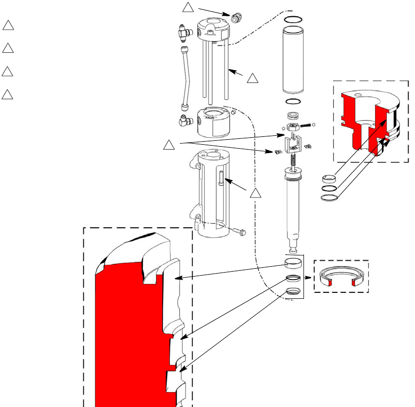
Compensator Seal Replacement
Removal
1. Relieve pressure, page 5. Allow hydraulic system to
cool before beginning the service procedure.
2. Remove screw(197) and pump handle cover (196).
Remove four cover bolts (79) and cover (140).
NOTE: It is not necessary to remove the hydraulic
lines before removing the cover. The cover is
designed to provide ample room for the cover to fit
over the hose.
3. Remove compensator screws and seperate com-
pensator and adapter block.
4. Install new gaskets and torque screws.
5. Install cover (140) with four screws (79). Torque to
25-30 in-lb (2.8 - 3.4 Nzm). Install pump handle
cover (196) with screw (197).
ti7805b
140
79
196
197
Torque 50 in-lbs
4 plcs
Adapter
Block
O-Ring
Gasket
O-Ring
Lubricate before installation
ti17601a
Gasket
Note Gasket Orientation
Compensator
Assembly
Torque 50 in-lbs
4 plcs
1
4
3
2
Torque sequence: 1-2-3-4-1
All cap screws must be tightened
When compensator assembled to
Gasket Adaptor Block. Do not
pre-tighten cap screws.
ti7111b
140
197 196 79
Displacement Pump Replacement
10 311283E
Displacement Pump Replacement
See manual 311485 for pump repair instructions.
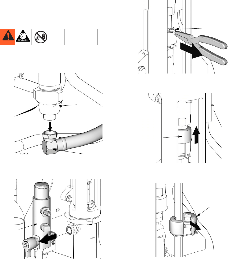
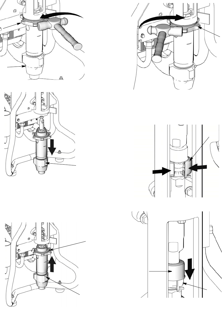
Removal
1. Flush pump (36). Stop pump on down stroke if
possible.
2. Relieve pressure, page 5.
3. Remove suction set (147) from pump (36).
4. Remove filter housing (110), page 16.
5. Remove clip (121).
6. Slide cover up (124).
7. Separate coupling (125) and remove.
36
147
ti7119
110
121
ti7789
124
ti7816
ti7814
125
Displacement Pump Replacement
311283E 11
8. Loosen jam nut (122) with a hammer. Unscrew
pump (36) from power head.
9. Remove pump (36).
Installation
1. Screw jam nut (122) to bottom of pump threads (36).
2. Slide cover (124) up over pump rod. Screw pump
completely up into power head.
3. Hand tighten jam nut (122). Then tighten securely
1/8 to 1/4 turn with hammer or torque to 330 ft-lb
(447.4 N•m).
4. Slide cover (124) up over pump rod. With engine in
OFF position, pull recoil starter to move rod until it
contacts pump rod.
5. Install coupling (125) around pump rod.
6. Slide cover (124) over coupling (125).
ti7782
122
36
ti7804
36
36
122
ti7779
ti7817
122
ti7771
125
ti7815
125
124
Pump Power Head Replacement
311283E 13
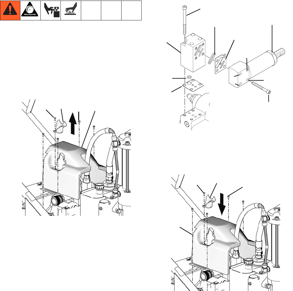
Pump Power Head Replacement
Removal
1. Relieve pressure, page 5.
2. Remove hydraulic lines (100, 101) from head (75).
3. Loosen (4) mounting bolts (7) on the adapter
enough to lift and remove assembly.
4. Remove power head from unit.
Installation
1. Install power head on unit.
100 101
75
ti7803
7
ti7841
ti7847
ti7851
Pump Power Head Replacement
14 311283E
2. Tighten power head bolts (7). Torque bolts to 400 +
10 in-lb (45 + 1 N•m).
3. Attach hoses (100, 101) to head (75). Torque to 450
+ 10 in-lb (50.84 N•m).
4. To purge air from hydraulic lines, increase pressure
enough to start hydraulic motor stroking and allow
fluid to circulate for 15 seconds.Turn pressure
down. Turn prime valve horizontal (closed).
ti7853
101
100
75
ti7777
Hydraulic Motor
311283E 15
Hydraulic Motor
1
2
3
4
1
450 in-lb (51 N.m)
600 in-lb (68 N.m)
60 in-lb (7 N.m)
930 in-lb (105 N.m)
Torqued in 3 steps
2
3
4
ti7868
Filter Housing Replacement
16 311283E
Filter Housing Replacement
Removal
1. Relieve pressure, page 5.
2. Remove paint and drain lines from filter housing.
3. Loosen filter housing fitting (110) until housing and
remove housing from pump.
Installation
1. Install filter housing (110) in pump opening.
2. Tighten fitting.
3. Attach paint and drain lines.
ti7845
ti7119
110
ti7772
110
ti7850
Torque to 225 + 10 in-lb. (25.4+ 1.1 N.m)
Hydraulic Pump Replacement
311283E 17
Hydraulic Pump Replacement
Changing Hydraulic Oil
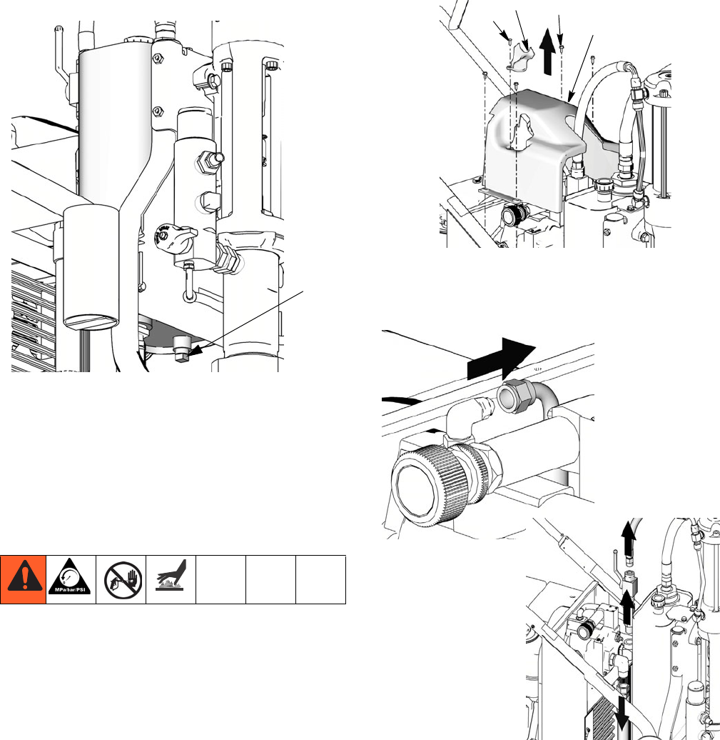
Draining Oil
a. Place drain pan under oil tank and drain plug.
b. Unscrew reservoir (64) drain plug and drain oil
from reservoir.
Refilling Oil
a. Replace drain plug.
b. Fill tank with Graco Hydraulic Oil, ISO 46. Tank
holds approximately 4 gallons.
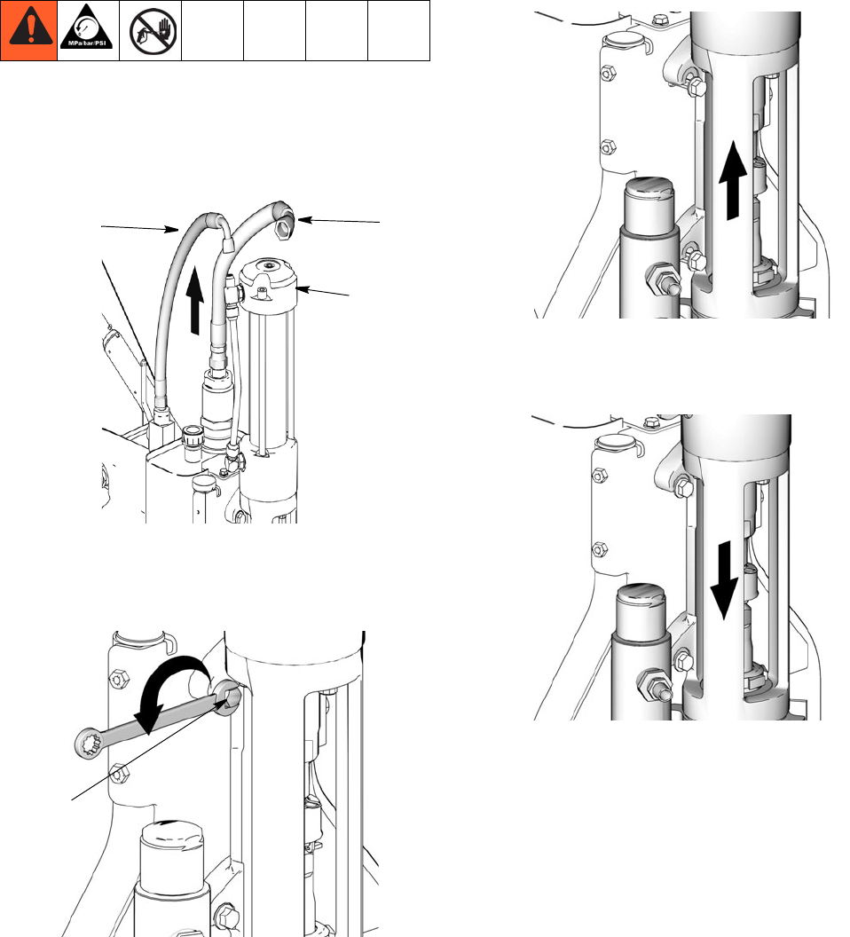
Removal
1. Relieve pressure, page 5. Allow hydraulic system
to cool before beginning the service procedure.
2. Drain oil, Changing Hydraulic Oil procedure,
page 17.
3. Remove screw (197) and pump handle cover (196).
Remove four cover bolts (79) and cover (140). (It is
not necessary to remove the hydraulic lines before
removing cover. The cover is designed to provide
ample room for the cover to fit over the hose.)
4. Unscrew suction line connections to hydraulic
pump. Place a container under hoses to catch any
dripping oil.
drain
plug
ti7784
79
140
ti7805b
197196
ti7790
ti7801
Hydraulic Pump Replacement
18 311283E
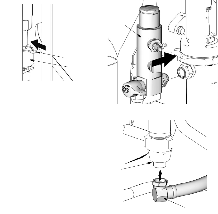
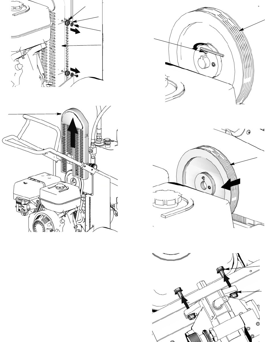
5. Remove (4) belt cover screws (79), washers (78)
and grommets (80) (2 each side).
6. Remove belt cover (67).
7. Remove belt (19), page 21.
8. Loosen set-screws (87) on front of large pulley (4).
9. Remove pulley (4) from hydraulic pump shaft.
10. Remove nuts (10) and screws (9) holding pump to
frame.
78
67
ti7796
80
79
67
ti7795
4
87
ti7783
4
ti7807
9
10
ti7788
Hydraulic Pump Replacement
311283E 19
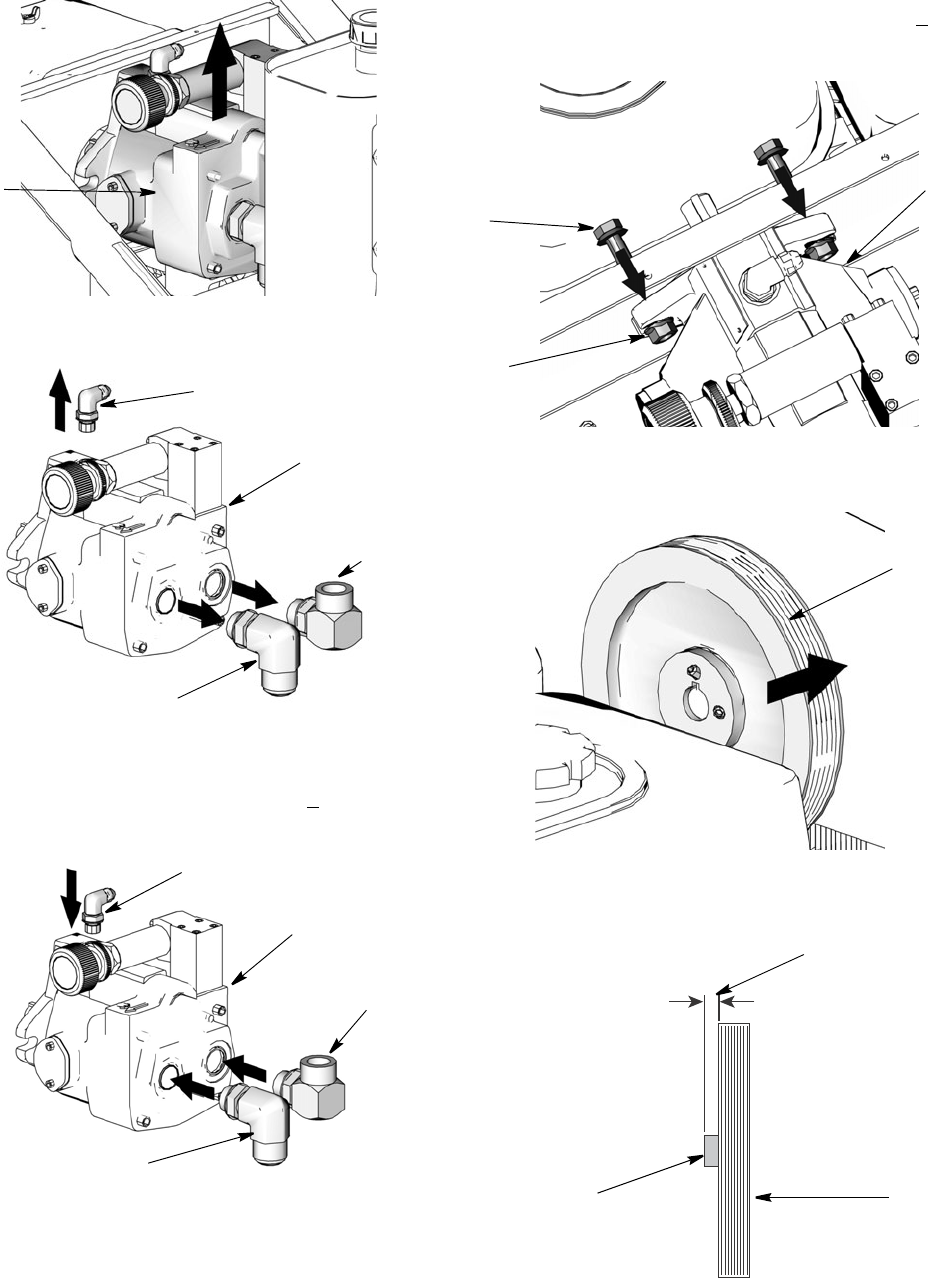
11. Remove hydraulic pump (3).
12. Remove fittings (30, 34, 35) from pump (3) and set
aside to use on the new pump.
Installation
1. Install fittings (30, 34, 35) from old pump on new
pump. Torque fitting 30 and 35 to 600 + 10 in-lb
(67.8 N.m). Torque fitting 34 to 450 in-lb (50.8 N.m).
NOTE: Fill pump casing with hyraulic oil before installing
fitting (34).
2. Install new pump (3) in frame.
3. Install screws (9) and nuts (10). Torque to 225 + 10
in-lb (25.42 N.m).
4. Replace large pulley (4) on hydraulic pump shaft.
5. Align pulley (4) on shaft. When properly positioned
approximately 1/8 inch of shaft (139) will protrude.
3
ti7800
34
35
30
3
ti7816
(
34
3
35
30
ti7816
10
9
3
ti7778
4
ti7813
1/8 inch
4
139
ti7835
Hydraulic Pump Replacement
20 311283E
6. Replace set-screws (87). Tighten and torque to 60 +
2 in-lb (6.8 + 0.2 N•m).
NOTE: Tighten set-screw on shaft before tightening
set-screw on pump shaft.
7. Position belt (19) over pulleys (4, 6); Installing Belt,
page 21.
8. Replace belt cover (67) and grommets (80), wash-
ers (78) and screws (79), (2 each side). Torque
screws to 25-30 in-lb (2.8 -3.4 N•m).
9. Install suction lines. Tighten fittings. Torque fitting A
to 225 + 10 in-lb (25.4 + 1.1 N.m). Fitting B to 450
+10 in-lb (50.1 + 1.1. N.m). Fitting C to 225 in-lb
(25.4 N.m).
10. Install cover (140) and with four screws (79). Torque
to 25-30 in-lb (2.8 - 3.4 N•m). Install pump handle
cover (196) with screw (197).
11. Fill oil tank following Refilling Oil procedure on
page 17.
67
79
ti7810
ti7812
78
80
ti7767
ti7889
A
B
C
79
140
ti7111b
197 196
Hydraulic Pump Replacement
311283E 21
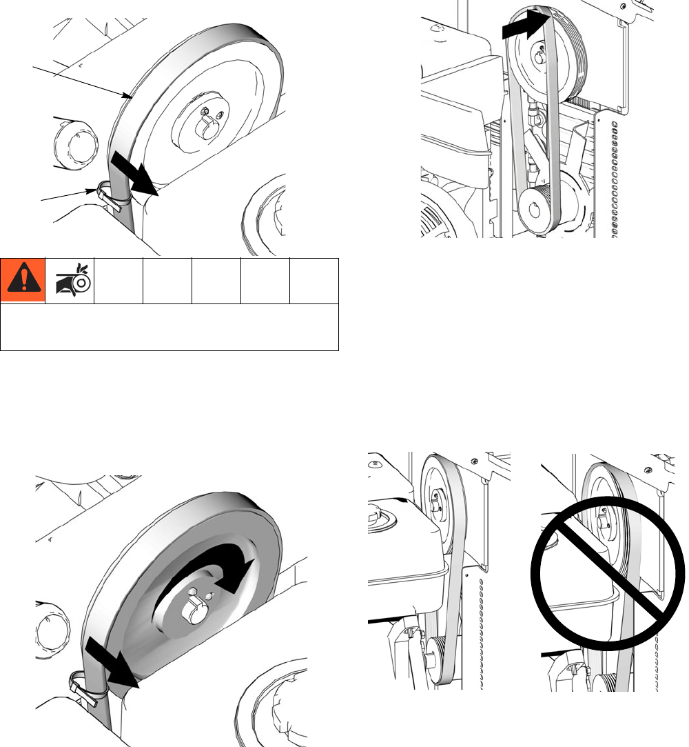
Belt Removal and Replacement
(recommended method)
Removing Belt
a. Place a ziptie around belt (19).
b. Slowly pull ziptie toward you while at the same
time slowly pulling engine recoil to rotate pul-
leys. It may be necessary to reposition zip tie
and repeat this procedure a few times to com-
pletely remove belt from pulley.
Installing Belt
a. Put belt over lower pulley (6) and align correctly.
b. Line up belt over top left side of large pulley (4).
c. With the palm of your hand, hold the belt snug
to large pulley while at the same time slowly pull
engine recoil to rotate pulleys.
d. Check belt (19) alignment on both large (4) and
small pulley (6). When properly positioned over
pulleys, belt is centered on pulleys and com-
pletely over all grooves.
NOTE: If belt is not aligned properly, to adjust belt, slowly
pull engine recoil while at the same time pushing or pull-
ing belt to reposition over pulley.
Moving parts can pinch or amputate fingers and other
body parts. To avoid serious injury be sure engine is in
OFF position before pulling engine recoil.
19
ziptie
ti7843
ti7842
ti7869
Properly Aligned Not Aligned Properly
ti7834 ti7837
Hydraulic Pump Replacement
22 311283E
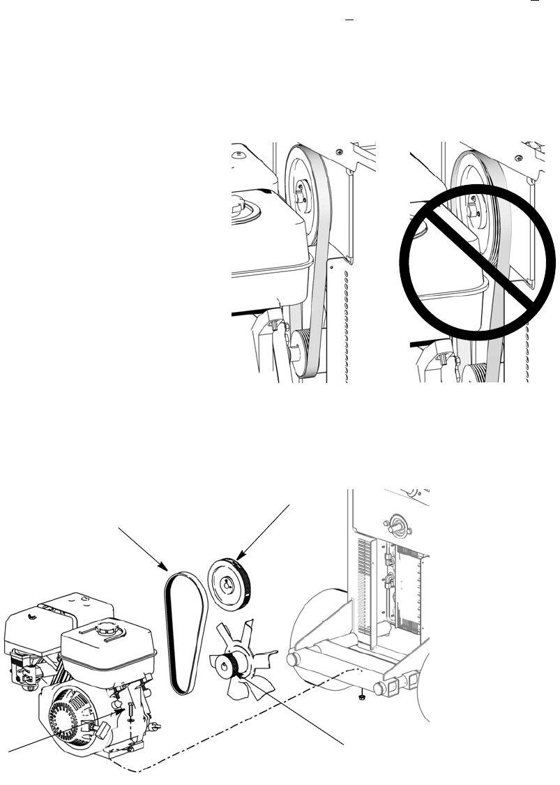
Alternate Belt Removal and Installation
Removing Belt
a. Loosen engine bolts (21) to relieve tension on
belt.
b. Slide belt off pulleys.
Installing Belt
a. Install belt (19) over small (6) and large (4)
pulleys.
b. Tighten engine bolts (21). Torque to 225 + 10
in-lb (25.4 + 1.1 N.m).
c. Check belt (19) alignment on both large (4) and
small pulley (6). When properly positioned over
pulleys, belt should be centered on pulleys and
completely over all grooves.
NOTE: If belt is not aligned properly, to adjust belt, slowly
pull engine recoil while at the same time pushing or pull-
ing belt to reposition over pulley.
Properly Aligned Not Aligned Properly
ti7834 ti7837
4
6
19
21
ti7870
Hydraulic Pump Replacement
311283E 23
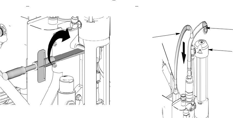
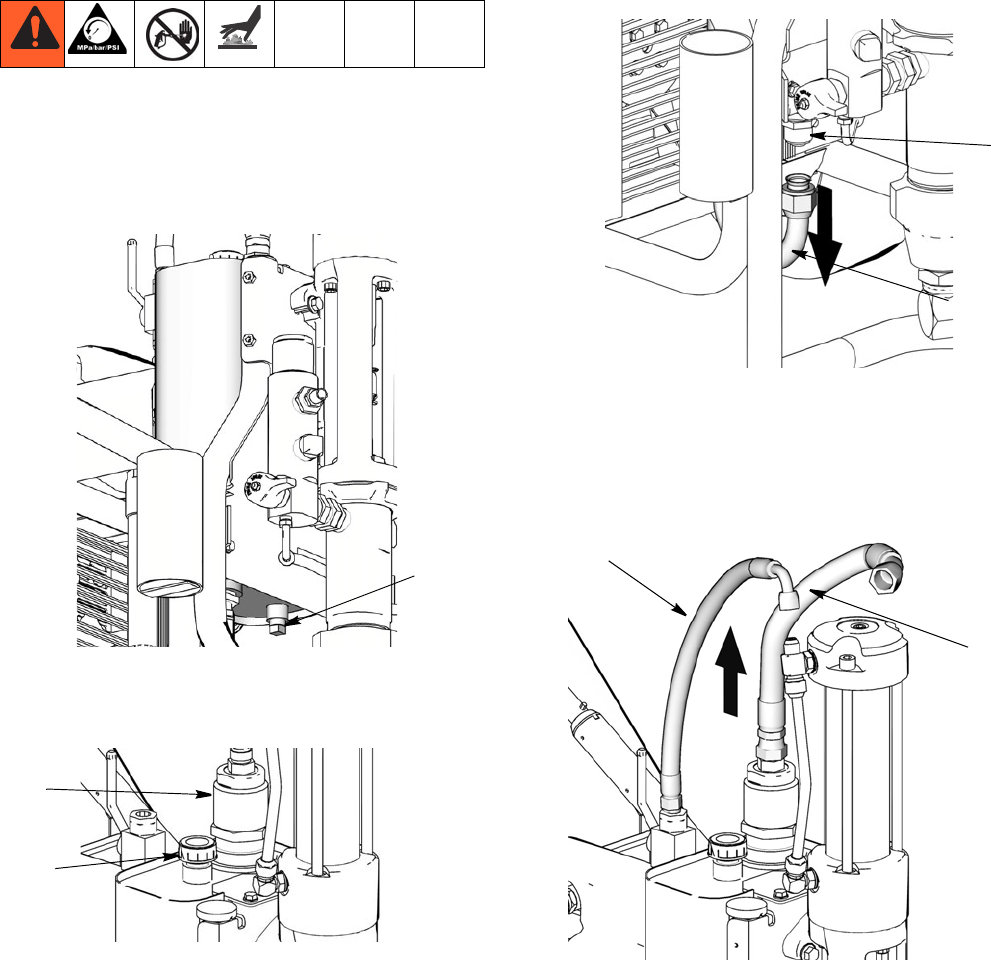
Replacing Oil Reservoir
Removal
1. Relieve pressure, page 5.
2. Drain oil from reservoir (64) following Draining Oil
procedure, page 17. Keep plug for use on new res-
ervoir.
3. Remove fill cap (27) and filter assembly (111). Keep
for use on new reservoir.
4. Loosen and remove suction hose (153).
5. Remove and keep suction fitting (32) for use on new
reservoir.
6. Loosen and remove return lines (100, 101).
Drain Plug
ti 7784
27
111
ti7785
153
ti7785
32
101
ti7803
100
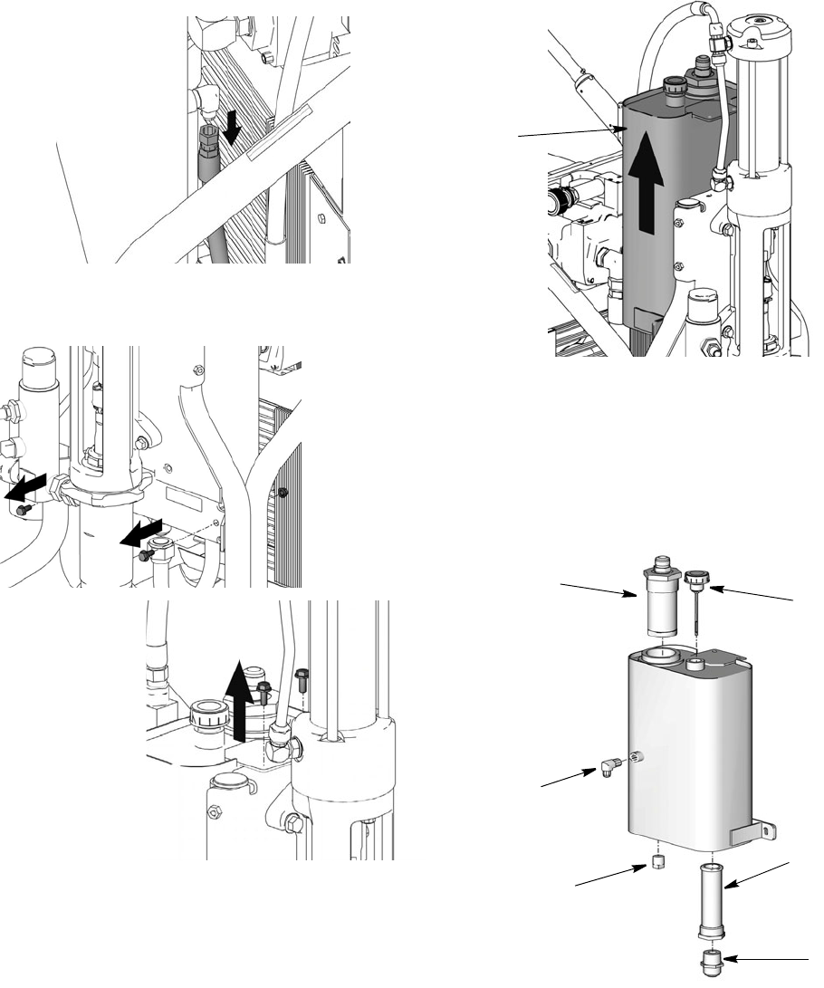
Hydraulic Pump Replacement
24 311283E
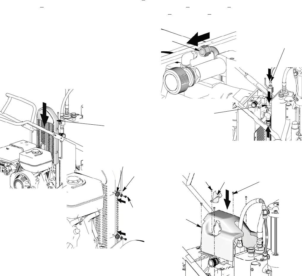
7. Remove cooler line from reservoir (64).
8. Remove (2) top bolts (86) and 2 bottom nuts (84)
securing reservoir (64) to frame.
9. Lift reservoir (64) out of frame.
Installation
1. Install plug (102), return elbow (31), suction fitting
(32), inlet screen (89) and filter assembly (111) in
new reservoir (64).
ti7791
ti7846
ti7786
64
ti7806
27
111
32
102
31
89
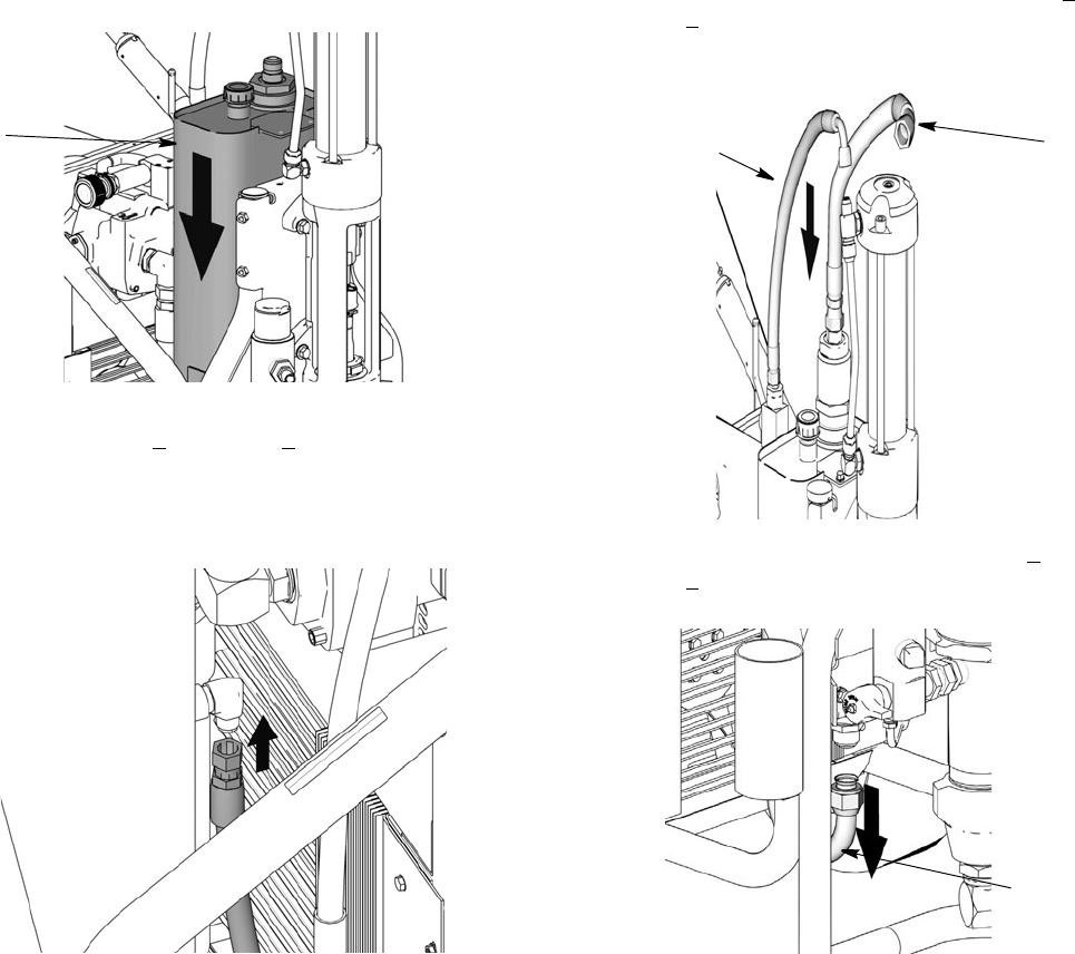
Hydraulic Pump Replacement
311283E 25
2. Install new reservoir (64) in frame.
3. Replace bolts (86) and nuts (84). Tighten bolts.
Torque to 125 + 10 in-lb 14 + 1.1 N•m).
4. Connect coolant line to reservoir (64). Torque to 225
in-lb (14.1 N.m).
5. Reattach return lines (100, 101). Torque to 450 + 10
in-lb (51 + 1.1 N•m).
6. Reattach suction hose (153). Toque to 600 + 10
in-lb (68 + 1.1 N•m).
64
ti7781
ti7766
101
ti7777
100
153
ti7785
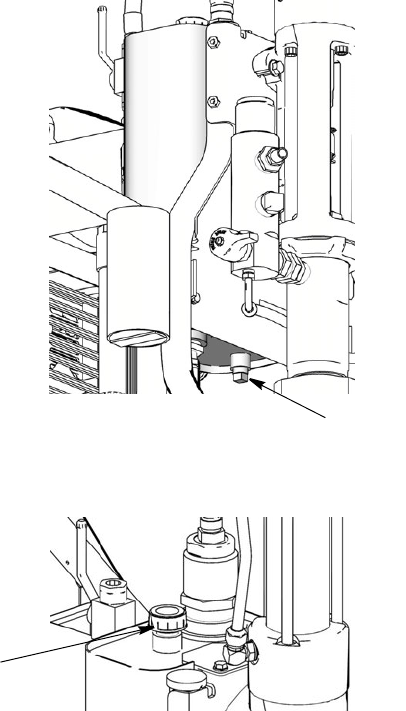
Hydraulic Pump Replacement
26 311283E
7. Verify drain plug has been replaced. Fill oil reservoir
with oil to high mark on dip stick (approximately 3.5
gallons).
8. Replace cap (27).
Drain Plug
ti7784
27
ti7785
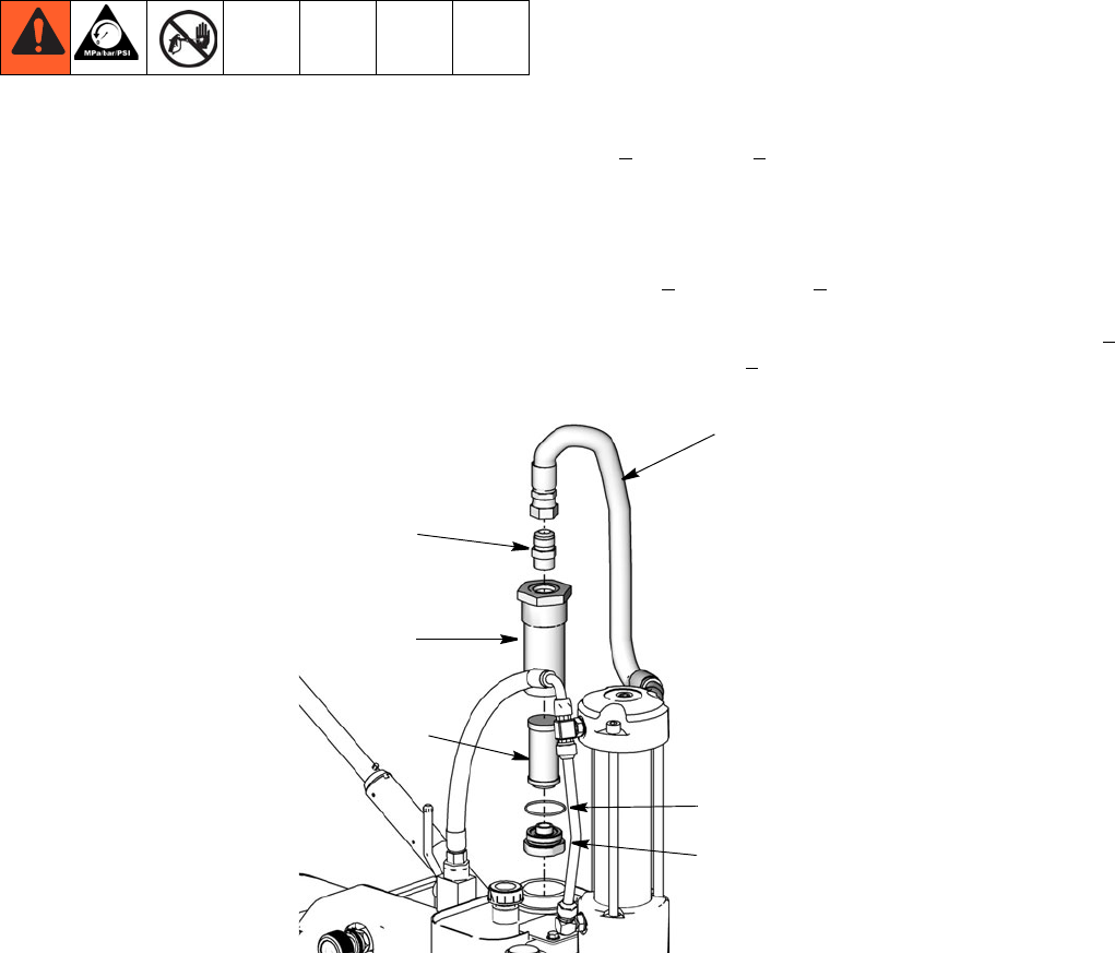
Changing Hydraulic Fluid Filter
311283E 27
Changing Hydraulic Fluid Filter
Removal
1. Relieve pressure, page 5.
2. Loosen and remove hose (101) from fitting (103).
3. Remove filter housing (111) from reservoir (64).
4. Remove bottom filer cap (155) from housing (111).
5. Pull filter (108) off cap (155).
Installation
1. Install new o-ring (113) from kit.
2. Install new filter (108) over cap (155).
3. Install cap (155) and filter (108) in filter housing
(111). Hand tighten cap till snug. Then torque to 375
+ 10 in-lb (42 + 1.1 N•m).
4. Install filter housing (111) into reservoir.
5. Install fitting (103) in filter housing (111). Torque to
600 + 10 in-lb (67.8 + 1.1 N.m).
6. Reattach hose (101) to fitting (103). Torque to 450 +
10 in-lbs (51 + 1.1 N•m).
103
111
155
113
101
108
ti7763
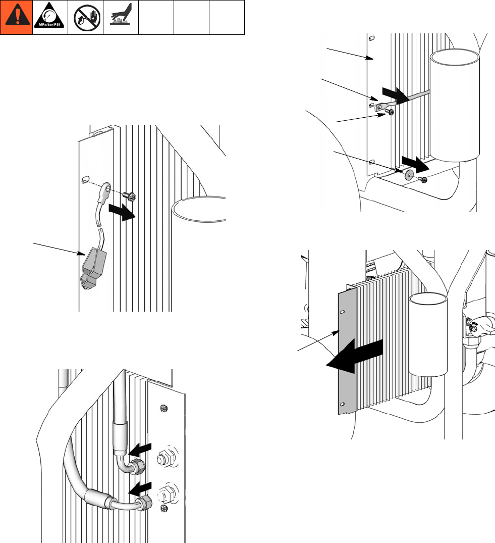
Cooler Replacement
28 311283E
Cooler Replacement
Removal
1. Relieve pressure, page 5.
2. Loosen ground screw and remove ground clamp
(95) from sprayer.
3. Loosen and remove return line to oil tank and
hydraulic line to cooler.
4. Remove screws (79), washers (78) and support bar
(77) from cooling coil (72).
5. Remove coil (72) from sprayer frame.
95
ti7799
ti7802
72
77
79
78
ti7794
72
ti7792
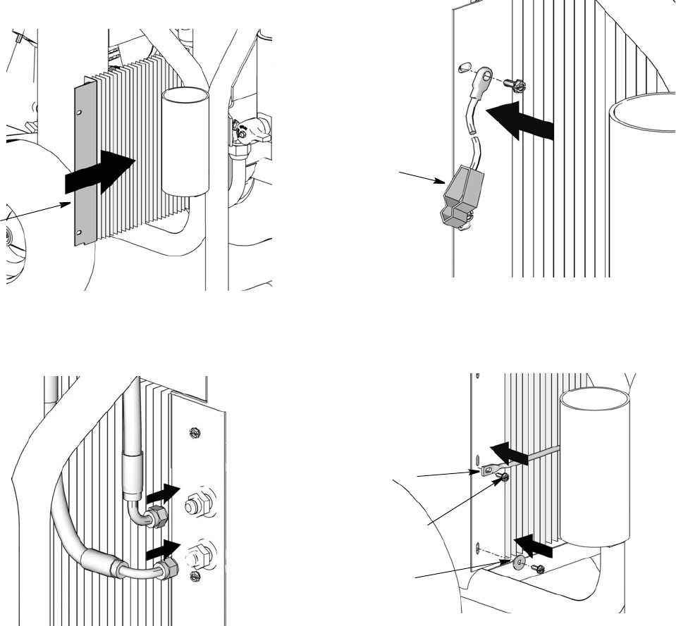
Cooler Replacement
311283E 29
Installation
1. Install new coil (72). Replace support bar (77),
washers (78) and screws (79). Tighten screws.
2. Reconnect return line to oil tank and hydraulic line
to cooler. Torque to 225 in-lb (25.4 N.m).
3. Replace ground wire (95) and tighten screw. Torque
to 25-30 in-lbs (2.8 - 3.4 N.m).
4. Replace bar and screws. Torque to 25-30 in-lb
(2.8-3.4 N.m).
72
ti776 8
ti7776
95
ti7774
78
79
77
Motor Replacement
30 311283E
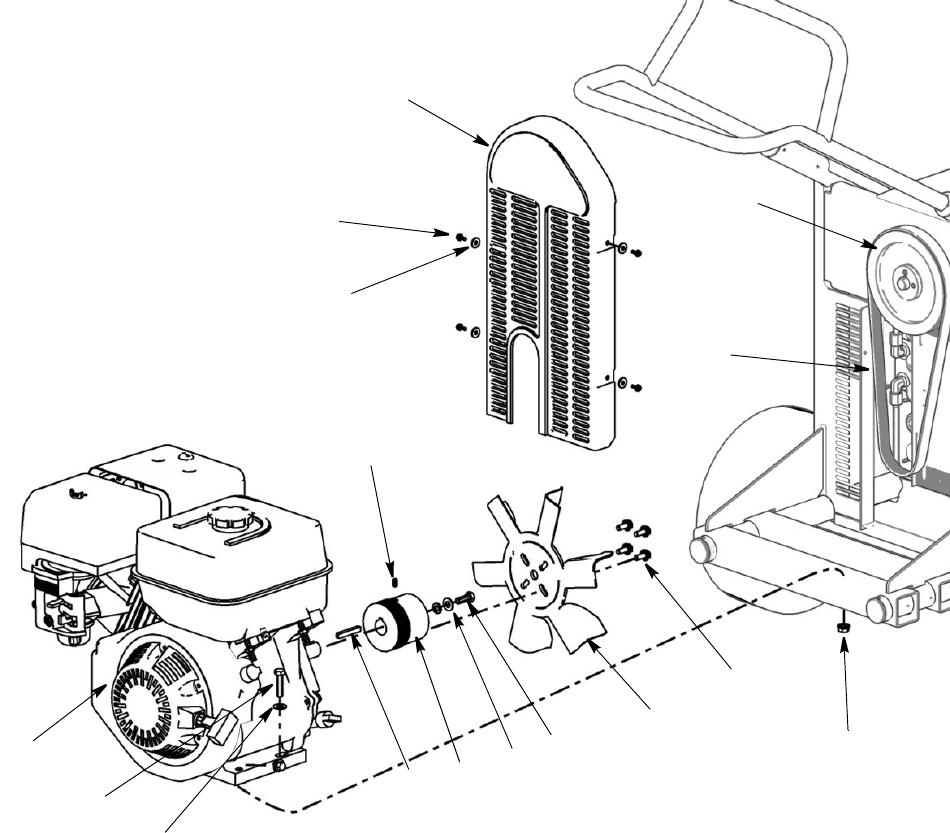
Motor Replacement
Removal
1. Relieve pressure, page 5.
2. Remove screws (79) and washers (78) and belt
cover (67).
3. Remove belt (19), page 21.
4. Remove screws (21), washers (70) and nuts (10)
securing motor (5) to frame.
5. Remove motor (5) from frame.
Replacing Motor Fan
Removal
a. Loosen and remove bolts (86) on front of fan
(14).
b. Pull fan (14) off small pulley (6).
Installation
a. Position new fan (14) over small pulley (6).
b. Replace bolts (86) and tighten securely.Torque
to 125 + 10 in-lb (14.1 + 1.1 N.m).
Removing Pulley (6)
NOTE: This procedure is only necessary if you
are replacing the motor. When you install a new
motor you reuse the existing pulley.
Removal
a. Loosen set screw (87) located on the side of the
pulley (6).
b. Remove large bolt (24) in the center of pulley
(6).
c. Pull pulley (6) off motor (5).
Installation
a. Position new pulley (6) on motor (5).
b. Install large bolt (24) and washer (65) in center
of pulley (6). Torque to 125 + 10 in-lb (14.1 + 1.1
N.m).
c. Tighten set screw (87). Torque to 60 + 2 in-lb
(25.4 N.m).
Installation
1. Install motor (5) in frame.
2. Replace all screws (21), washers (70) and nuts (10).
Tighten securely.
3. Install belt (19) over pulleys (4, 6), page 21.
4. Replace belt cover (67) and screws (79) and wash-
ers (78) (2 each side). Using a wrench tighten bolts.
Torque to 25-30 in-lb (2.8-3.4 N.m).
Motor Replacement
311283E 31
5
21
70
80 665 24
14
86
10
87
78
79
67
4
19
ti7797
Removing Handle
32 311283E
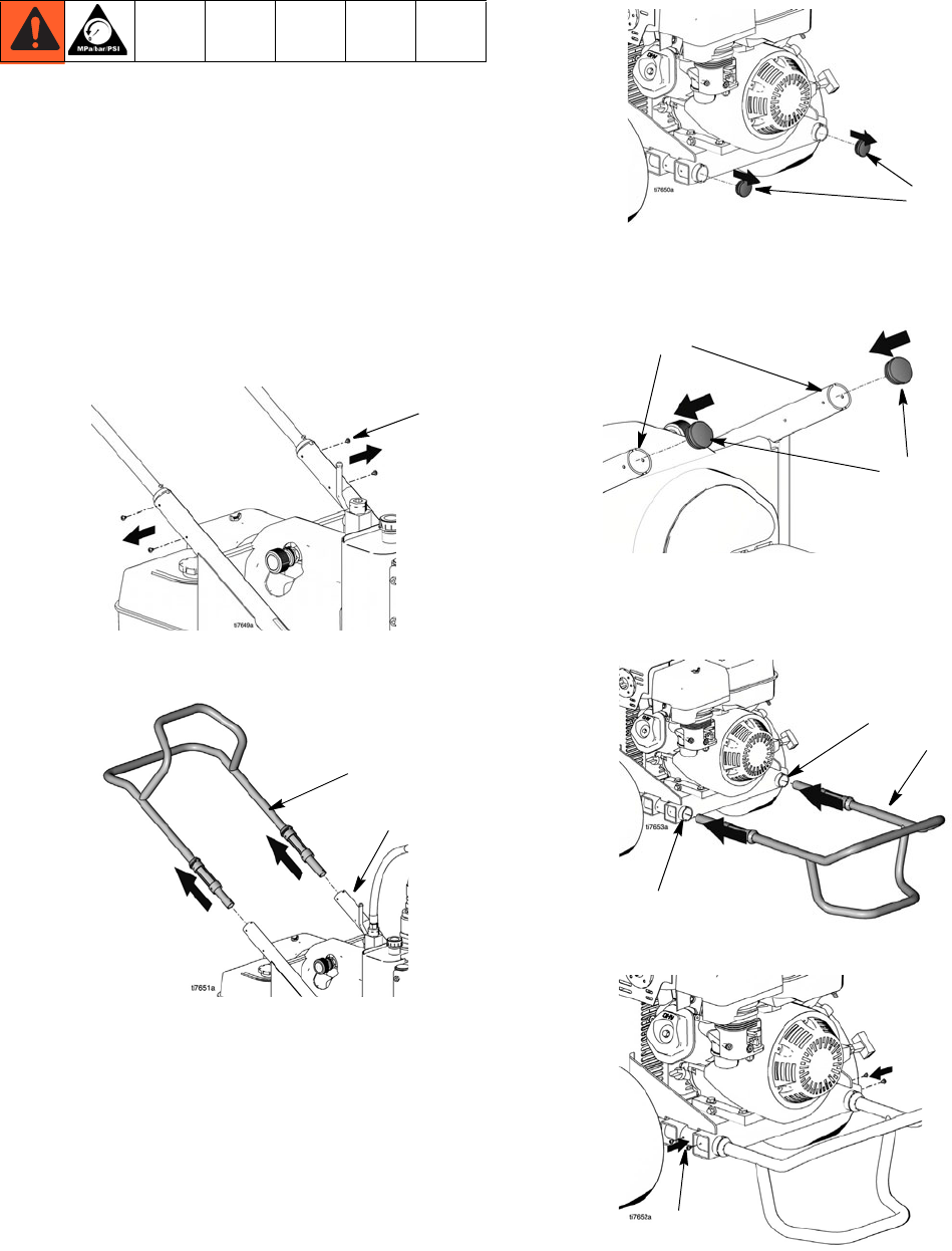
Removing Handle
Fixed Mounting (optional)
To prevent damaging the unit when transporting it in
a truck or on a trailer, Graco recommends fixed
mounting to the vehicle.
Repositioning Handle
Before you can secure the unit to a truck or trailer bed,
you must reposition the handle.
1. Remove the 4 handle sleeve screws (143).
2. Remove handle assembly (25) by pulling it out of
upper frame tubes (1).
3. Remove frame tube plugs (120) located behind the
wheels.
4. Insert plugs (120) in upper frame handle tubes (a).
5. Insert handle assembly (25) into lower frame tubes
(b). The hose bracket should face down. Adjust to
appropriate in/out location.
6. Install sleeve screws (143) in lower frame tubes.
143
25
1
120
120
(a)
2525
(b)
(b)
143
Removing Handle
311283E 33
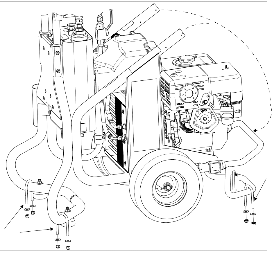
Securing Unit to Vehicle Bed
For fixed mounting, fasten U-bolts over sprayer frame as
indicated in the following illustration.
1. Reposition handle, steps 1-5, page 32.
2. Place U-bolts over sprayer frame and through holes
in vehicle bed. Place a washer and nut over bolt
end. Using a wrench, tighten nut securely.
U-bolts
U-bolts
Reposition Handle
Technical Data
34 311283E
Technical Data
Sprayer GH833 Gas
Hydraulic Pressure psi (bar) 2750 (19.0)
Hydraulic Reservoir Capacity Gallon (liters) 4.0 (15.1)
Motor HP (kW) Honda 13 (9.7)
Maximum Delivery gpm (lpm) 4.0 (15.1)
Maximum Tip Size
• 1 gun .065
• 2 guns .046
• 3 guns .037
• 4 guns .032
• 5 guns .028
• 6 guns .026
Fluid Inlet inches 1-1/2 to 11-1/2 NPT (m)
Fluid Outlet inches 1 to 11-1/2 NPT (f)
Dimensions
Weight lb (kg) 360 (163)
Height inch (cm) 40 (101.6)
Width inch (cm) 27 (68.6)
Length inch (cm) 47 (119.3)
Sound Levels*
Sound Pressure 91 dB(A)
Sound Power 106 dB(A)
*measured at maximum normal load conditions
Graco-Approved Hydraulic Oil
169236 - 5 gallons (19 liters)
207428 - 1 gallon (3.8 liters)

Notes
311283E 35
Notes
All written and visual data contained in this document reflects the latest product information available at the time of publication.
Graco reserves the right to make changes at any time without notice.
Original instructions. This manual contains English. MM 311283
Graco Headquarters: Minneapolis
International Offices: Belgium, China, Japan, Korea
GRACO INC. P.O. BOX 1441 MINNEAPOLIS, MN 55440-1441
Copyright 2006, Graco Inc. is registered to ISO 9001
www.graco.com
Revised 06/2011
Graco Standard Warranty
Graco warrants all equipment referenced in this document which is manufactured by Graco and bearing its name to be free from defects in
material and workmanship on the date of sale to the original purchaser for use. With the exception of any special, extended, or limited warranty
published by Graco, Graco will, for a period of twelve months from the date of sale, repair or replace any part of the equipment determined by
Graco to be defective. This warranty applies only when the equipment is installed, operated and maintained in accordance with Graco’s written
recommendations.
This warranty does not cover, and Graco shall not be liable for general wear and tear, or any malfunction, damage or wear caused by faulty
installation, misapplication, abrasion, corrosion, inadequate or improper maintenance, negligence, accident, tampering, or substitution of
non-Graco component parts. Nor shall Graco be liable for malfunction, damage or wear caused by the incompatibility of Graco equipment with
structures, accessories, equipment or materials not supplied by Graco, or the improper design, manufacture, installation, operation or
maintenance of structures, accessories, equipment or materials not supplied by Graco.
This warranty is conditioned upon the prepaid return of the equipment claimed to be defective to an authorized Graco distributor for verification of
the claimed defect. If the claimed defect is verified, Graco will repair or replace free of charge any defective parts. The equipment will be returned
to the original purchaser transportation prepaid. If inspection of the equipment does not disclose any defect in material or workmanship, repairs will
be made at a reasonable charge, which charges may include the costs of parts, labor, and transportation.
THIS WARRANTY IS EXCLUSIVE, AND IS IN LIEU OF ANY OTHER WARRANTIES, EXPRESS OR IMPLIED, INCLUDING BUT NOT LIMITED
TO WARRANTY OF MERCHANTABILITY OR WARRANTY OF FITNESS FOR A PARTICULAR PURPOSE.
Graco’s sole obligation and buyer’s sole remedy for any breach of warranty shall be as set forth above. The buyer agrees that no other remedy
(including, but not limited to, incidental or consequential damages for lost profits, lost sales, injury to person or property, or any other incidental or
consequential loss) shall be available. Any action for breach of warranty must be brought within two (2) years of the date of sale.
GRACO MAKES NO WARRANTY, AND DISCLAIMS ALL IMPLIED WARRANTIES OF MERCHANTABILITY AND FITNESS FOR A
PARTICULAR PURPOSE, IN CONNECTION WITH ACCESSORIES, EQUIPMENT, MATERIALS OR COMPONENTS SOLD BUT NOT
MANUFACTURED BY GRACO. These items sold, but not manufactured by Graco (such as electric motors, switches, hose, etc.), are subject to
the warranty, if any, of their manufacturer. Graco will provide purchaser with reasonable assistance in making any claim for breach of these
warranties.
In no event will Graco be liable for indirect, incidental, special or consequential damages resulting from Graco supplying equipment hereunder, or
the furnishing, performance, or use of any products or other goods sold hereto, whether due to a breach of contract, breach of warranty, the
negligence of Graco, or otherwise.
FOR GRACO CANADA CUSTOMERS
The Parties acknowledge that they have required that the present document, as well as all documents, notices and legal proceedings entered into,
given or instituted pursuant hereto or relating directly or indirectly hereto, be drawn up in English. Les parties reconnaissent avoir convenu que la
rédaction du présente document sera en Anglais, ainsi que tous documents, avis et procédures judiciaires exécutés, donnés ou intentés, à la suite
de ou en rapport, directement ou indirectement, avec les procédures concernées.
Graco Information
For the latest information about Graco products, visit www.graco.com.
TO PLACE AN ORDER, contact your Graco distributor or call 1-800-690-2894 to identify the nearest distributor.
