Graco 312375J Check Mate Lowers Users Manual Instructions Parts, English
l500cm bc008d6d-d209-4a9c-a9e9-cd7cd43ca17c Graco Marine Sanitation System L500CM User Guide |
2015-04-02
: Graco Graco-312375J-Check-Mate-Lowers-Users-Manual-685897 graco-312375j-check-mate-lowers-users-manual-685897 graco pdf
Open the PDF directly: View PDF ![]() .
.
Page Count: 44
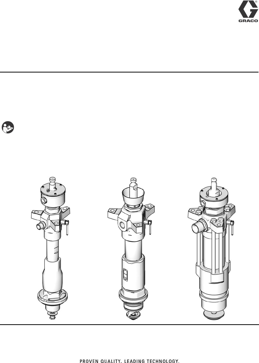
With priming piston and Severe Duty® or MaxLife® rod and cylinder.
For professional use only.
Not for use in explosive atmospheres.
See page 3 for model information. See page 42 for maximum working pressure and approvals.
Important Safety Instructions
Read all warnings and instructions in this manual.
Save these instructions.
Instructions - Parts
Check-Mate®
Displacement Pumps
ti10720a
L200CS Model
ti10392a ti10396a
L500CM Model
L100CM Model
312375J
EN

Related Manuals
2312375J
Contents
Related Manuals . . . . . . . . . . . . . . . . . . . . . . . . . . . 2
Models . . . . . . . . . . . . . . . . . . . . . . . . . . . . . . . . . . . 3
Warnings . . . . . . . . . . . . . . . . . . . . . . . . . . . . . . . . . 4
Component Identification . . . . . . . . . . . . . . . . . . . . 6
Repair . . . . . . . . . . . . . . . . . . . . . . . . . . . . . . . . . . . . 7
Troubleshooting . . . . . . . . . . . . . . . . . . . . . . . . . . 7
Disassembly and Reassembly of Throat Packings
and Cartridge . . . . . . . . . . . . . . . . . . . . . . . . 7
Disassembly . . . . . . . . . . . . . . . . . . . . . . . . . . . . 8
Reassembly . . . . . . . . . . . . . . . . . . . . . . . . . . . 12
Parts . . . . . . . . . . . . . . . . . . . . . . . . . . . . . . . . . . . . 18
60cc Displacement Pumps . . . . . . . . . . . . . . . . 18
100cc Displacement Pumps . . . . . . . . . . . . . . . 19
200cc and 250cc Displacement Pumps . . . . . . 24
500cc Displacement Pumps . . . . . . . . . . . . . . . 34
Dimensions . . . . . . . . . . . . . . . . . . . . . . . . . . . . . . 39
Outlet Housing Mounting Hole Layout . . . . . . . . 40
Technical Data . . . . . . . . . . . . . . . . . . . . . . . . . . . . 42
Graco Standard Warranty . . . . . . . . . . . . . . . . . . . 44
Graco Information . . . . . . . . . . . . . . . . . . . . . . . . 44
Related Manuals
Component Manuals in U.S. English:
Manual Description
312376 Check-Mate® Pump Packages
Instruction-Parts
313526 Supply Units Operation
313527 Supply Units Repair-Parts
313528 Tandem Supply Units Operation
313529 Tandem Supply Units Repair-Parts
Models
312375J 3
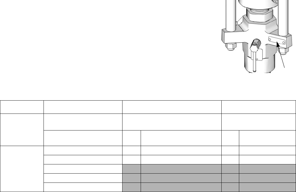
Models
Check your displacement pump’s identification plate (ID) for the 6-digit part number
of your displacement pump. Use the following matrix to define the construction of
your displacement pump, based on the six digits. For example, displacement pump
Part No. L250CM represents the displacement pump (L), output volume in cc per
cycle (250), carbon steel construction (C), and MaxLife® coatings, packings, and
enclosed wet cup (M).
To order replacement parts, see Parts section starting on page 18. The digits in the
matrix do not correspond to the Ref. Nos. in the Parts drawings and lists.
ID
ti10622a
L 250 C M
First Digit Second, Third, and Fourth
Digits Fifth Digit Sixth Digit
Displacement Pump Volume
per cycle (cc) Material
Coatings, Packings,
Enclosed Wet Cup
L
(displacement
pump)
60 C Carbon Steel S Severe Duty
100 S Stainless Steel M MaxLife
200
250
500
Warnings
4312375J
Warnings
The following warnings are for the setup, use, grounding, maintenance, and repair of this equipment. The exclama-
tion point symbol alerts you to a general warning and the hazard symbol refers to procedure-specific risk. Refer back
to these warnings. Additional, product-specific warnings may be found throughout the body of this manual where
applicable.
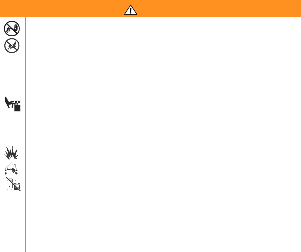
WARNING
SKIN INJECTION HAZARD
High-pressure fluid from gun, hose leaks, or ruptured components will pierce skin. This may look like just
a cut, but it is a serious injury that can result in amputation. Get immediate surgical treatment.
• Do not point gun at anyone or at any part of the body.
• Do not put your hand over the spray tip.
• Do not stop or deflect leaks with your hand, body, glove, or rag.
• Do not spray without tip guard and trigger guard installed.
• Engage trigger lock when not spraying.
• Follow Pressure Relief Procedure in this manual, when you stop spraying and before cleaning,
checking, or servicing equipment.
MOVING PARTS HAZARD
Moving parts can pinch or amputate fingers and other body parts.
• Keep clear of moving parts.
• Do not operate equipment with protective guards or covers removed.
• Pressurized equipment can start without warning. Before checking, moving, or servicing equipment,
follow the Pressure Relief Procedure in this manual. Disconnect power or air supply.
FIRE AND EXPLOSION HAZARD
Flammable fumes, such as solvent and paint fumes, in work area can ignite or explode. To help prevent
fire and explosion:
• Use equipment only in well ventilated area.
• Eliminate all ignition sources; such as pilot lights, cigarettes, portable electric lamps, and plastic drop
cloths (potential static arc).
• Keep work area free of debris, including solvent, rags and gasoline.
• Do not plug or unplug power cords, or turn power or light switches on or off when flammable fumes
are present.
• Ground all equipment in the work area. See Grounding instructions.
• Use only grounded hoses.
• Hold gun firmly to side of grounded pail when triggering into pail.
• If there is static sparking or you feel a shock, stop operation immediately. Do not use equipment
until you identify and correct the problem.
• Keep a working fire extinguisher in the work area.
Warnings
312375J 5
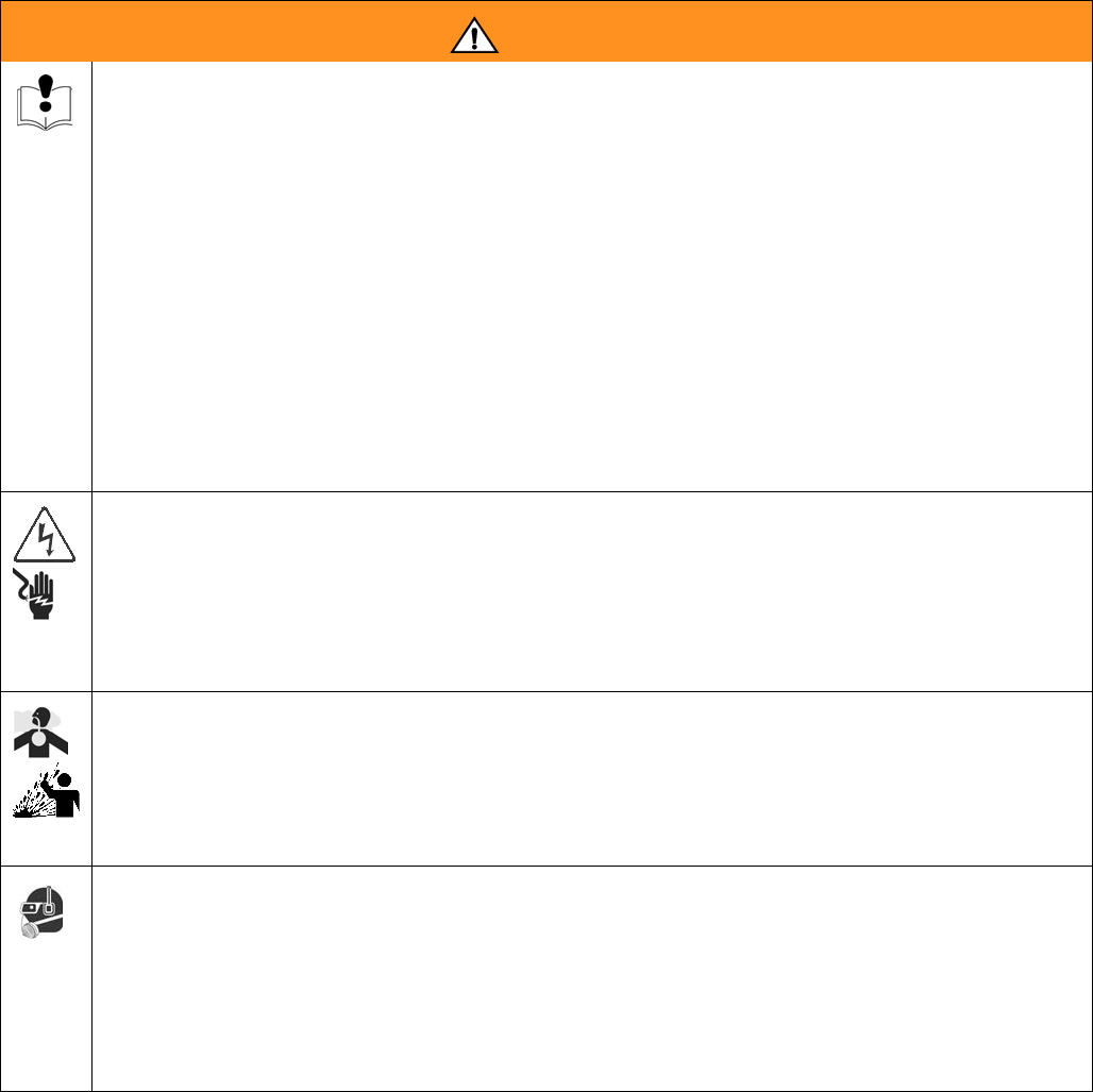
EQUIPMENT MISUSE HAZARD
Misuse can cause death or serious injury.
• Do not operate the unit when fatigued or under the influence of drugs or alcohol.
• Do not exceed the maximum working pressure or temperature rating of the lowest rated system
component. See Technical Data in all equipment manuals.
• Use fluids and solvents that are compatible with equipment wetted parts. See Technical Data in all
equipment manuals. Read fluid and solvent manufacturer’s warnings. For complete information
about your material, request MSDS forms from distributor or retailer.
• Check equipment daily. Repair or replace worn or damaged parts immediately with genuine manu-
facturer’s replacement parts only.
• Do not alter or modify equipment.
• Use equipment only for its intended purpose. Call your distributor for information.
• Route hoses and cables away from traffic areas, sharp edges, moving parts, and hot surfaces.
• Do not kink or over bend hoses or use hoses to pull equipment.
• Keep children and animals away from work area.
• Comply with all applicable safety regulations.
ELECTRIC SHOCK HAZARD
Improper grounding, setup, or usage of the system can cause electric shock.
• Turn off and disconnect power cord before servicing equipment.
• Use only grounded electrical outlets.
• Use only 3-wire extension cords.
• Ensure ground prongs are intact on sprayer and extension cords.
• Do not expose to rain. Store indoors.
TOXIC FLUID OR FUMES HAZARD
Toxic fluids or fumes can cause serious injury or death if splashed in the eyes or on skin, inhaled, or
swallowed.
• Read MSDS’s to know the specific hazards of the fluids you are using.
• Store hazardous fluid in approved containers, and dispose of it according to applicable guidelines.
• Always wear impervious gloves when spraying or cleaning equipment.
PERSONAL PROTECTIVE EQUIPMENT
You must wear appropriate protective equipment when operating, servicing, or when in the operating
area of the equipment to help protect you from serious injury, including eye injury, inhalation of toxic
fumes, burns, and hearing loss. This equipment includes but is not limited to:
• Protective eyewear
• Clothing and respirator as recommended by the fluid and solvent manufacturer
•Gloves
• Hearing protection
WARNING
Component Identification
6312375J
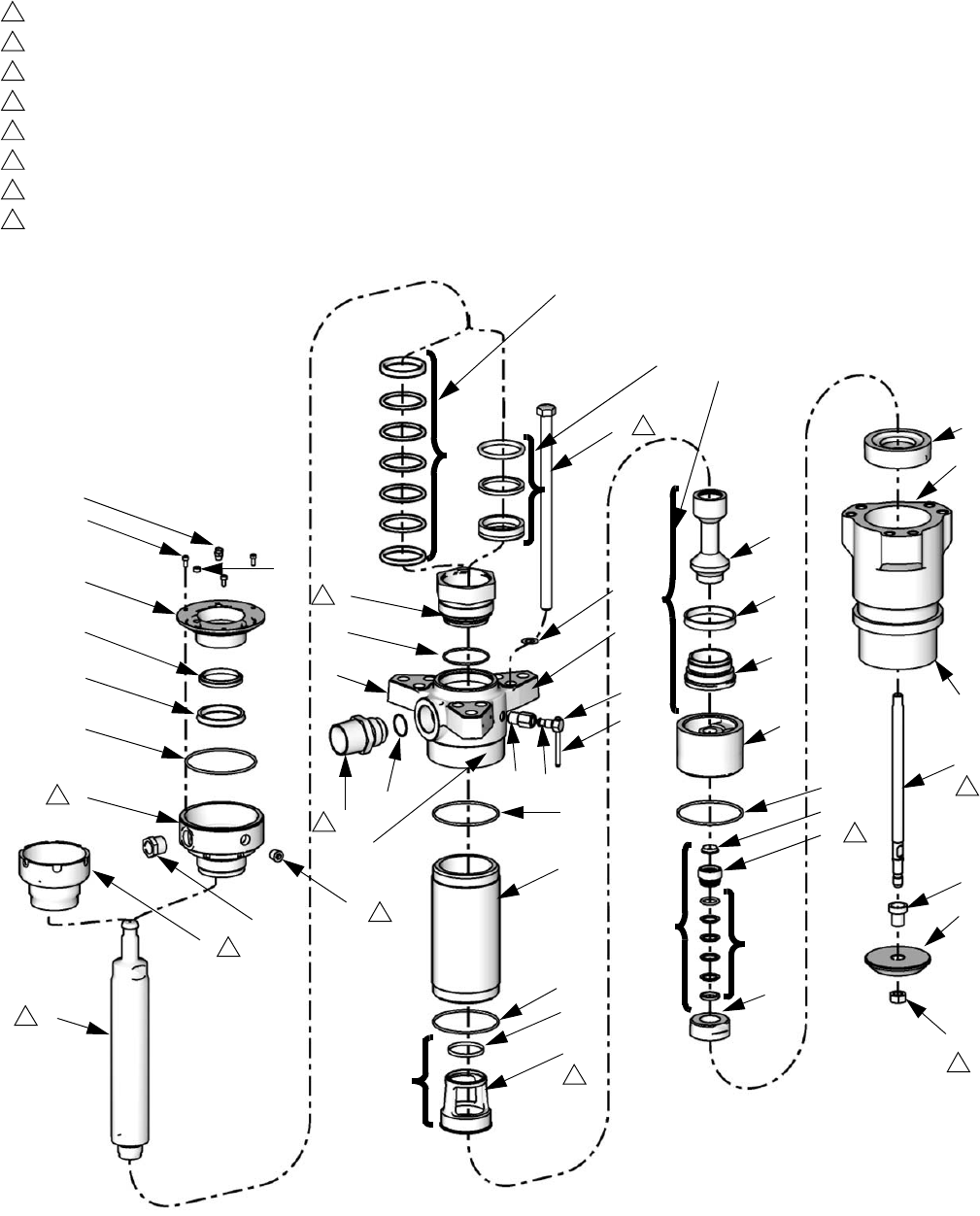
Component Identification
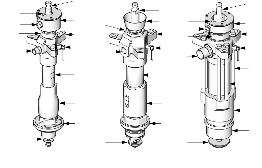
Key:
A Displacement Rod
BWet Cup
C Throat Packing Cartridge
D Outlet Housing
E Fluid Outlet
F Pump Bleed Valve
G Pump Cylinder
H Intake Valve Housing
J Intake Cylinder
K Priming Piston Assembly
L Hex Head Bolt (500cc displacement pumps only)
M Wet Cup Sight Glass (MaxLife models only)
N Wet Cup Fill Cap (MaxLife models only)
FIG. 1
A
B
CD
EF
G
H
J
K
ti10720a
ti10392a ti10396a
L200CS and L250CS Models L500CM Model
L060CM and L100CM Models
M
NA
B
C
D
EF
G
H
J
K
A
B
CD
E
F
G
H
J
K
M
N
L
Repair
312375J 7
Repair
Troubleshooting
See Check-Mate Pump Packages manual 312376.
Required Tools
• Torque wrench
• Bench vise, with soft jaws
• Rubber mallet
•Hammer
• 400 mm (15.8 in.) adjustable wrench
• O-ring pick
• Flat head screwdriver
• 13 mm (1/2 in.) dia. brass rod
• Set of socket wrenches
• Set of adjustable wrenches
• Packing nut wrench (supplied with
pump package)
• 24 in. (610 mm) adjustable wrench
• M4 hex key wrench
• Thread lubricant
• Thread sealant
•Loctite
® 2760™ or equivalent
Disassembly and Reassembly of
Throat Packings and Cartridge
All new Check-Mate displacement pumps are equipped
with a throat packing cartridge (3) that enables easy
removal and replacement of throat packings without the
complete disassembly of the displacement pump.
1. Run air motor and displacement pump to bottom of
stroke.
2. Relieve pressure. See Check-Mate Pump Packages
manual 312376 for instructions.
3. Remove air motor coupling assembly from displace-
ment rod. See Check-Mate Pump Packages manual
312376 for instructions.
4. Push air motor piston rod up to top of stroke.
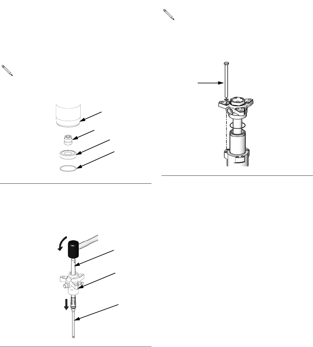
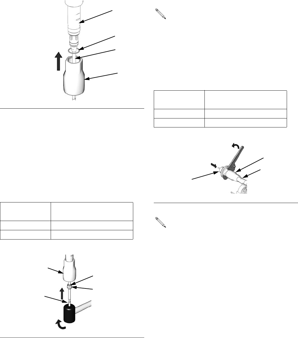
5. Remove wet cup cover (present on enclosed wet
cups only).
6. Place an absorbent cloth in wet cup (9) to absorb
Throat Seal Liquid (TSL).
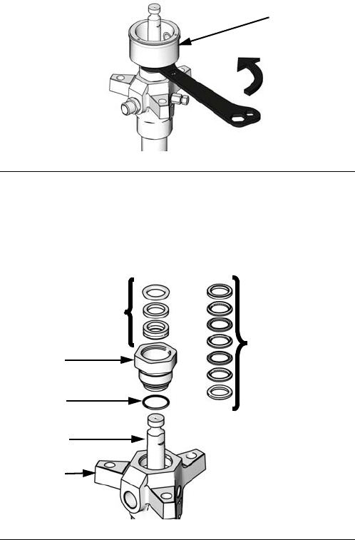
7. Use packing nut wrench (supplied) to loosen and
remove packing nut/enclosed wet cup (9).
8. Use an adjustable wrench to loosen cartridge (3);
slide it and throat packings (P) up and off displace-
ment rod (1).
9. Replace throat packings (P) according to specific
packing kit into cartridge (3). See Packing Kits in
Parts starting on page 18.
10. Remove and replace o-ring (4).
11. Slide cartridge (3) and throat packings (P) back on
to displacement rod (1). Be careful to not damage
packings.
FIG. 2
FIG. 3
9
ti10623a
P
P
3
4
1
2
ti11118a
(Severe Duty)
(MaxLife)
Repair
8312375J
12. Torque cartridge (3) to specified torque listed in the
following table.
13. Slide packing nut/wet cup (9) over displacement rod
(1) and torque to specified torque listed in the follow-
ing table.
14. Fill wet cup (9) 1/3 full of TSL or compatible solvent.
Disassembly
When disassembling displacement pump, lay out all
removed parts in sequence to ease reassembly. Clean
all parts with a compatible solvent and inspect them for
wear or damage.
1. Relieve pressure. See your Check-Mate Pump
Packages manual 312376 for instructions.
2. Disconnect displacement pump from air motor as
illustrated in your Check-Mate Pump Packages
manual 312376.
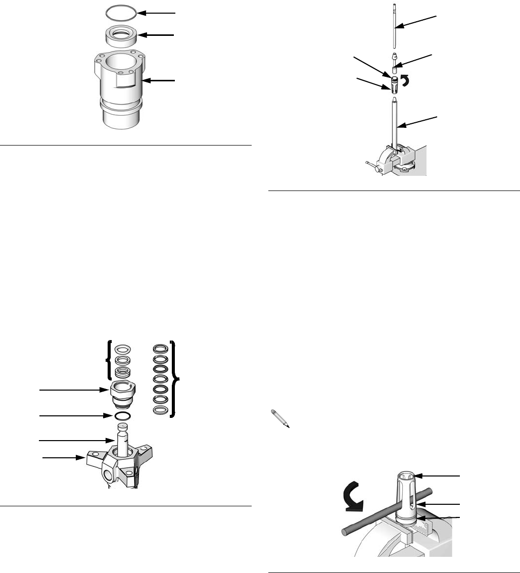
3. Place displacement pump in a vise, with jaws on
outlet housing (2).
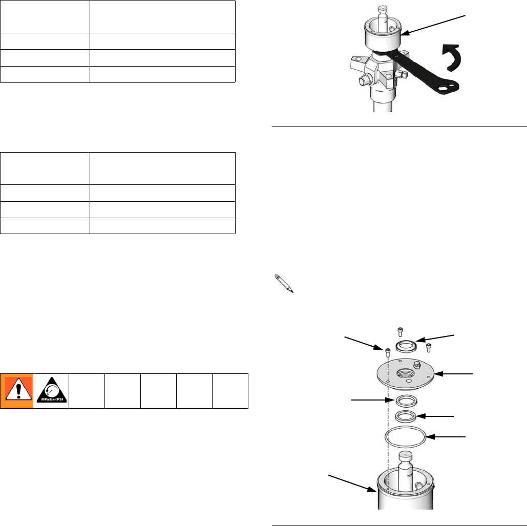
4. Use packing nut wrench (supplied) to loosen and
remove packing nut/enclosed wet cup (9).
5. On displacement pumps with enclosed wet cups (9),
use an M4 hex wrench to remove the three screws
(14) from wet cup cover (10) and remove cover.
Drain and clean out the wet cup (9). See FIG. 5.
6. On displacement pumps with enclosed wet cups (9),
use o-ring pick to remove o-ring (11), and a flat
head screwdriver to remove snap ring (61), wiper
(15), and seal (16).
Displacement
Pump Torque
60cc and 100cc 90-130 ft-lbs (122-173 N•m)
200cc and 250cc 130-190 ft-lbs (176-258 N•m)
500cc 149-261 ft-lbs (203-355 N•m)
Displacement
Pump Torque
60cc and 100cc 28-44 ft-lbs (38-59 N•m)
200cc and 250cc 95-115 ft-lbs (128-155 N•m)
500cc 95-115 ft-lbs (128-155 N•m)
FIG. 4
The snap ring (61) is applicable only to 60cc and
100cc displacement pumps.
FIG. 5
9
ti10623a
ti10561a
10
61
11
16
14
9
15
Repair
312375J 9
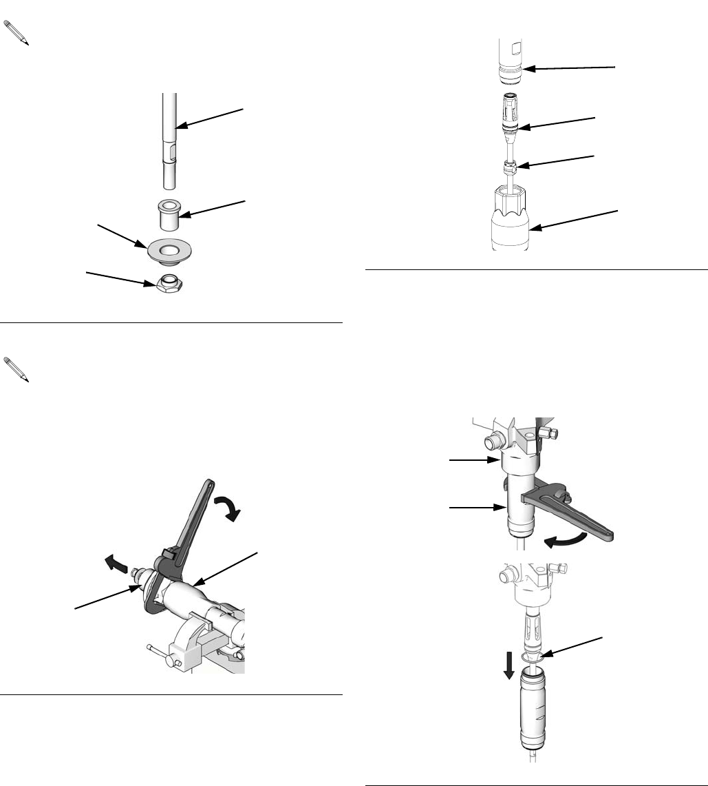
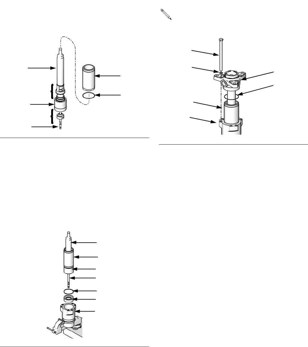
7. Hold flats of the priming piston rod (24) with an
adjustable wrench, and use a second wrench to
unscrew priming piston seat (27) from rod. Slide
priming piston (26) off rod. Inspect surfaces of guide
(25) and piston (26) for scoring, wear, or other dam-
age.
8. Use an adjustable wrench on hex of intake cylinder
(22) to unscrew it from intake valve housing (19).
9. Use an adjustable wrench to unscrew intake valve
housing (19) from cylinder (17) and outlet housing
(2). Pull intake valve housing off cylinder. Intake
check valve assembly (R) should slide down priming
piston rod (24) as you remove housing; if it does not
slide easily, firmly tap on top of housing (19) with a
rubber mallet to loosen.
10. Use a 400 mm adjustable wrench on flats of dis-
placement pump cylinder (17) and unscrew cylinder
from outlet housing (2). Remove o-rings (18).
Inspect inside surface of cylinder for wear, scoring
or other damage by holding it up to light at an angle
or running a finger over the surface.
The guide (25) is applicable only to 100cc and
500cc displacement pumps.
FIG. 6
Steps 8-13 apply to 60cc, 100cc, 200cc, and
250cc displacement pumps only.
FIG. 7
ti10563a
24
25
26
27
ti10562a
19
22
FIG. 8
FIG. 9
17
24
19
R
r_000000_312375_1
ti10565a
ti10601a
18
2
17
Repair
10 312375J
11. Use an o-ring pick to remove seal (21) from intake
valve housing (19). Discard seal; use a new one for
reassembly. See FIG. 10.
12. Pull intake seat (20) out bottom of intake valve hous-
ing (19). Take care not to drop intake valve assem-
bly (R) as it comes free, and set it aside for later.
13. Use a rubber mallet to drive displacement rod (1)
and priming piston rod (24) out of outlet housing (2).
Inspect outer surfaces of rods for damage by run-
ning a finger over the surface.
14. 500cc Displacement Pumps Only: use a socket
wrench to remove six capscrews (45).
15. Tap underside of outlet housing (2) with a rubber
mallet to loosen housing from cylinder (17). Lift out-
let housing off displacement pump and set it aside.
Be careful not to scratch displacement rod (1) while
removing housing. Remove seal (18) from top of cyl-
inder.
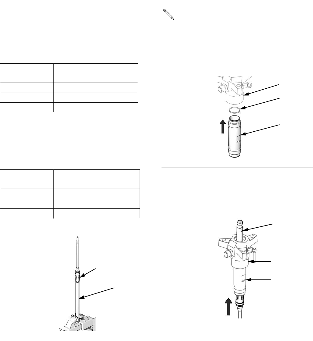
16. Lift cylinder (17) up off intake housing (22). Dis-
placement rod (1), piston assembly, intake valve
assembly, and priming piston rod (24) will come with
cylinder.
17. Place cylinder (17) sideways in a vise with soft jaws.
Using a rubber mallet on end of priming piston rod
(24), drive displacement rod (1) and piston assem-
bly out of the top of the cylinder. Continue to pull rod
out of cylinder until priming piston rod (24) comes
free.
18. Remove seal (18) from bottom of cylinder (17). Hold
cylinder up to light at an angle to examine inside
surface for scoring and damage.
If seat (20) is difficult to remove, insert a hammer
and brass rod through the top of housing (19) and
drive seat out.
FIG. 10
FIG. 11
r_000000_312375_2
19
20
21
R
ti10568a
1
2
24
Steps 14-19 apply to 500cc displacement
pumps only.
FIG. 12
45
ti10584a
Repair
312375J 11
19. Pull seal (18) and seat (20) out the top of the intake
housing (22). If seat is difficult to remove, turn hous-
ing upside down and drive seat out using a hammer
and brass rod.
20. Examine mating surfaces of seat (20) and intake
valve body (32) for damage.
21. To access throat packings and glands, use an
adjustable wrench to remove the throat cartridge
(3).
22. Remove cartridge o-ring (4). Then remove throat
packings (P) from throat cartridge (3). Some models
include a fluid outlet nipple (43) and o-ring (44). Do
not remove these parts from housing unless they
need replacement.
23. Place flats of displacement rod (1) in a vise.
Unscrew piston (23) from displacement rod; priming
piston rod (24) will come with it. Slide piston guide
(28) and seat (30) off piston (23).
24. Inspect outer surfaces of displacement rod (1) and
priming piston rod (24) for wear, scoring or other
damage by holding them up to light at an angle or
running a finger over the surface.
25. It is not necessary to remove priming piston rod (24)
from piston (23) unless your inspection reveals scor-
ing, wear, or other damage to either part. To disas-
semble, place piston flats in a vise and unscrew the
rod.
26. Place piston seat (30) and guide (28) in vise. Slide a
brass rod through openings in piston guide and
unscrew it from seat. Remove piston seal (31) and
guide bearing (29).
FIG. 13
FIG. 14
ti10566a
18
20
22
ti11118a
P
3
4
2
P
1
(MaxLife)
(Severe Duty)
FIG. 15
Guide bearing (29) is press-fit into the piston guide
(28), and may require cutting to ease removal.
FIG. 16:
ti10569a
24
23
1
28
30
28
30
ti10570a
29
Repair
12 312375J
27. To disassemble intake check valve assembly, place
intake valve body (32) in a vise and unscrew pack-
ing nut (33). Remove seal (38) from nut, and intake
valve packings (S) from valve body. Inspect mating
surfaces of intake valve body (32) and seat (20) for
damage or wear.
28. Unscrew bleeder valve plug (40) completely from
valve body (39). Clean valve threads and bleed
hole. It is not necessary to remove valve body from
displacement pump outlet housing (2).
29. Inspect all parts for damage. Clean all parts and
threads with a compatible solvent. Reassemble as
explained in the Reassembly section.
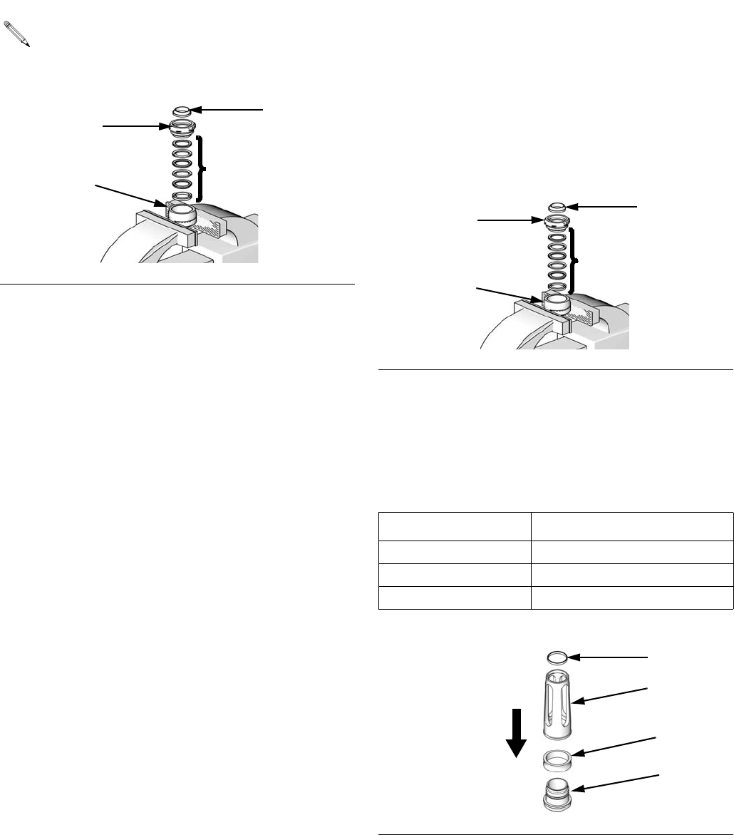
Reassembly
1. Lubricate the intake valve packings (S) and install
them in valve (32). See FIG. 18. See Packing Kits
sections for the correct intake valve packing configu-
ration.
2. With beveled side facing up, press intake valve seal
(38) in to recess of intake valve packing nut (33)
until it snaps into place. The nose of the seal should
be flush with or slightly recessed into the face of the
packing nut. See FIG. 18.
3. Place flats of valve body (32) in a vise. Screw pack-
ing nut (33) into valve body handtight. Set intake
housing assembly aside.
4. Lubricate piston seal (31) and install it on piston
seat (30). Screw piston guide (28) onto seat (30).
Place piston seat in a vise and use a brass rod to
torque guide; see the following table for correct
torque. Snap guide bearing (29) into piston guide
(28).
The seal (38) is press-fit in the nut (33) and may
require cutting to ease removal.
FIG. 17
ti10572a
38
S
33
32
FIG. 18
Displacement Pump Torque
60cc and 100cc 26-30 ft-lbs (35-41 N•m)
200cc and 250cc 57-63 ft-lbs (77-85 N•m)
500cc 90-100 ft-lbs (122-135 N•m)
FIG. 19
ti10572a
38
S
32
33
ti10573a
28
31
30
29
Repair
312375J 13
5. If it was necessary to remove the priming piston rod
(24) from the piston (23), apply thread sealant to
threads of the rod. Place flats of piston in a vise.
Hold flats of rod with an adjustable wrench, and
screw rod into piston; see the following table for cor-
rect torque. Be careful not to create burrs on flats of
rod.
6. Place flats of displacement rod (1) in a vise. Install
piston seat/guide assembly onto the piston (23).
Apply thread sealant to threads of rod and screw
piston assembly onto rod; see the following table for
correct torque.
7. Lubricate seal (18) and place it on top of the cylin-
der (17). Screw cylinder handtight into outlet hous-
ing (2). The cylinder is symmetrical so either end
can be the top.
8. Carefully insert displacement rod (1) into bottom of
cylinder (17). Push rod up into cylinder and through
outlet housing (2). Be careful not to damage piston
seal (31) while performing this step.
Displacement
Pump Torque
60cc and 100cc 34-38 ft-lbs (46-51 N•m)
200cc and 250cc 92-102 ft-lbs (124-138 N•m)
500cc 90-100 ft-lbs (122-135 N•m)
Displacement
Pump Torque
60cc and 100cc 85-95 ft-lbs (115-128 N•m)
200cc and 250cc 239-271 ft-lbs (323-366 N•m)
500cc 327-363 ft-lbs (441-490 N•m)
FIG. 20
ti10574a
1
piston assembly
Steps 7- 13 apply to 60cc, 100cc, 200cc, and
250cc displacement pumps only.
FIG. 21
FIG. 22
ti10575a
2
18
17
ti10577a
1
17
2
Repair
14 312375J
9. Lubricate seal (18) and install it on the bottom of cyl-
inder (17). Slide intake valve housing (19) onto prim-
ing piston rod (24). Ensure smooth surface of valve
stop faces displacement pump intake. Screw hous-
ing onto cylinder.
10. Lubricate priming piston rod (24), then slide assem-
bled intake valve onto rod. Ensure packing nut (33)
goes on rod first. Push valve assembly up rod, stop-
ping before it reaches intake valve housing (19).
See FIG. 24.
11. Hold valve body (32) steady with a wrench while
using an adjustable wrench to tighten packing nut
(33); see the following table for correct torque. Use a
rubber mallet on priming piston rod (24), to drive
valve assembly up to stop.
12. The intake seat (20) is reversible on the 200cc and
250cc displacement pumps. Inspect both sides of
seat and install it with the best side facing into hous-
ing (19). Push it into housing until it seats securely.
Lubricate seal (21) and install in the bevel around
the bottom of the seat.
13. Lubricate threads of intake cylinder (22). Use an
adjustable wrench to screw intake cylinder into
intake valve housing (19). Torque intake cylinder;
see the following table for correct torque. This will
also torque intake valve housing (19) and displace-
ment pump cylinder (17) into outlet housing (2).
14. Slide rod guide (19) onto priming piston rod (24)
ensuring the end nearest valve stop goes on rod
first.
15. Slide assembled intake valve onto priming piston
rod (24) ensuring packing nut (33) goes on rod first.
Push valve assembly up rod, stopping before it
reaches rod guide (19).
16. Hold valve body (32) steady with a wrench while
using an adjustable wrench to tighten packing nut
(33). Torque to 71-78 ft-lbs (97-106 N•m). Use a
hammer and a brass rod to carefully drive valve
assembly further up rod until it reaches the stop.
FIG. 23
Displacement
Pump Torque
60cc and 100cc 43-47 ft-lbs (58-63 N•m)
200cc and 250cc 71-79 ft-lbs (96-107 N•m)
FIG. 24
ti10579a
17
18
24
19
ti10580a
33
32
24
19
For 60cc and 100cc displacement pumps, install
intake seat (20) so large beveled side faces down
toward pump intake.
Displacement
Pump Torque
60cc and 100cc 213-287 ft-lbs (288-387 N•m)
200cc and 250cc 345-435 ft-lbs (466-587 N•m)
FIG. 25
Steps 14-21 apply to 500cc displacement
pumps only.
ti10581a
19
17
22
Repair
312375J 15
17. Place cylinder (17) sideways in a vise with soft jaws.
18. Lubricate seal (18) and place it on bottom of cylin-
der (17). (Cylinder is symmetrical so either end can
be the bottom.)
19. Slide displacement rod (1), piston assembly (T),
intake valve assembly (R), and priming piston rod
(24) into cylinder (17) from bottom until mating sur-
faces of rod guide (19) and cylinder (17) meet.
20. Put intake housing (22) upright in a vise, making
sure it is off-center so there is a sufficient clearance
for priming piston rod (24) to be lowered through
housing. Insert intake seat (20) into intake housing
(22) so the flat seat is facing up. Lubricate seal (18)
and place it on top of intake seat (20). Lower rod
and cylinder assembly into intake housing until rod
guide (19) bottoms on intake seat (20) and priming
piston rod (24) protrudes from bottom of intake
housing (22).
21. Lubricate seal (18) and place it on top of cylinder
(17). Insert outlet housing (2) on to cylinder. Install
six long capscrews (45) through outlet housing (2)
and into intake housing (22). Using a socket wrench,
torque screws oppositely and evenly to 180-195
ft-lbs (244-264 N•m).
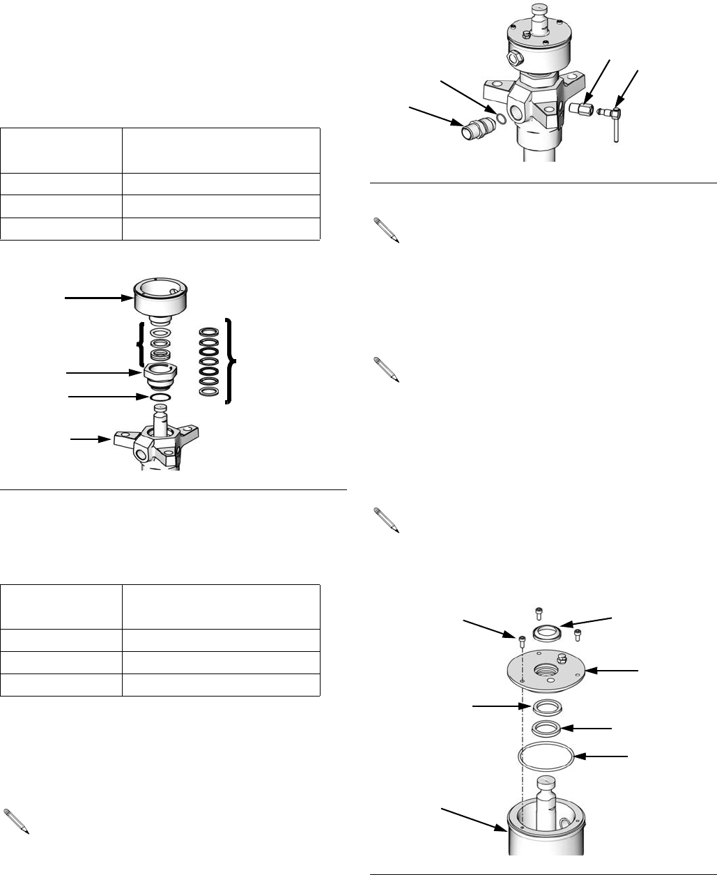
22. Lubricate throat packings (M), and install them in
throat cartridge (3) one at a time with the lips of the
v-packings or u-cup facing down. Refer to Packing
Kit sections for each displacement pump size for the
correct throat packing configuration for your dis-
placement pump.
FIG. 26
FIG. 27
ti111159a
17
18
1
19
24
T
R
ti10582a
19
20
22
24
18
1
17
L500SS and L500SM models: install washer (46)
between capscrews (45) and outlet housing (2).
FIG. 28
ti10584a
2
45
22
18
17
46
Repair
16 312375J
23. Partially thread wet cup (9) into cartridge (3) to hold
packings in place during installation. Install new car-
tridge o-ring (4) on cartridge (3). Apply thread lubri-
cant to cartridge (3) and carefully slide down over
displacement rod and into outlet housing (2). Torque
cartridge to the following torque. Be careful not to
damage throat packings on leading edge of rod.
24. Use packing nut wrench (supplied) to tighten wet
cup (9) to specified torque; refer to the following
table.
25. Lubricate the threads of the bleeder valve plug (40).
The plug has two sets of threads. Be sure to screw
the plug completely into the valve body (39). Torque
the plug to 9-11 ft-lbs (12-15 N•m).
26. Install new o-ring (11), wet cup wiper (15), seal (16),
and snap ring (61) into wet cup cover (10). See FIG.
31.
27. Carefully slide wet cup cover (10) over displacement
rod. Line up holes in cover and wet cup. Insert
screws (14). Use a hex head screwdriver to tighten
screws. See FIG. 31.
Displacement
Pump Torque
60cc and 100cc 90-130 ft-lbs (122-176 N•m)
200cc and 250cc 130-190 ft-lbs (176-257 N•m)
500cc 150-261 ft-lbs (203-355 N•m)
FIG. 29
Displacement
Pump Torque
60cc and 100cc 28-44 ft-lbs (38-59 N•m)
200cc and 250cc 95-115 ft-lbs (128-155 N•m)
500cc 95-115 ft-lbs (128-155 N•m)
Some models include an outlet nipple (43) and
o-ring (44). It is not ordinarily necessary to remove
these parts. However, if they were replaced
because of damage, lubricate o-ring and place it on
nipple. Screw nipple into outlet housing (2). Torque
to 44-62 ft-lbs (60-84 N•m).
ti10576a
4
3
2
P
P
(Severe Duty)
(MaxLife)
9
FIG. 30
Steps 26-27 apply only to displacement pumps
with enclosed wet cups.
The snap ring (61) is applicable only to 60cc and
100cc displacement pumps.
Use caution when sliding wet cup cover (10) over
displacement rod (1) to avoid damaging seals (15,
16).
FIG. 31
ti10585a
39 40
44
43
ti10561a
10
61
11
16
14
1, 9
15
Repair
312375J 17
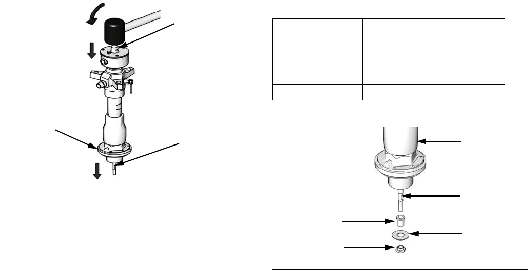
28. Check that flats of priming piston rod (24) are
accessible below intake cylinder (22). If not, tap on
top of displacement rod (1) with a rubber mallet until
flats are exposed.
29. Slide priming piston (26) and priming piston guide
(25) (only on L100 and L500 models) onto rod (24)
until it stops. Hold rod (24) steady with an adjustable
wrench on flats, and screw seat (27) onto rod with
another wrench. Torque to specified torque; refer to
the following table.
30. Reconnect displacement pump to the air motor as
explained in Check-Mate Pump Packages manual
312376.
31. Allow 2 hours for thread sealant to cure before
returning pump to service.
FIG. 32
ti10586a
1
24
22
Displacement
Pump Torque
60cc and 100cc 34-38 ft-lbs (46-51 N•m)
200cc and 250cc 57-63 ft-lbs (77-85 N•m)
500cc 71-79 ft-lbs (96-107 N•m)
FIG. 33
ti10587a
22
24
25
26
27
Parts
18 312375J
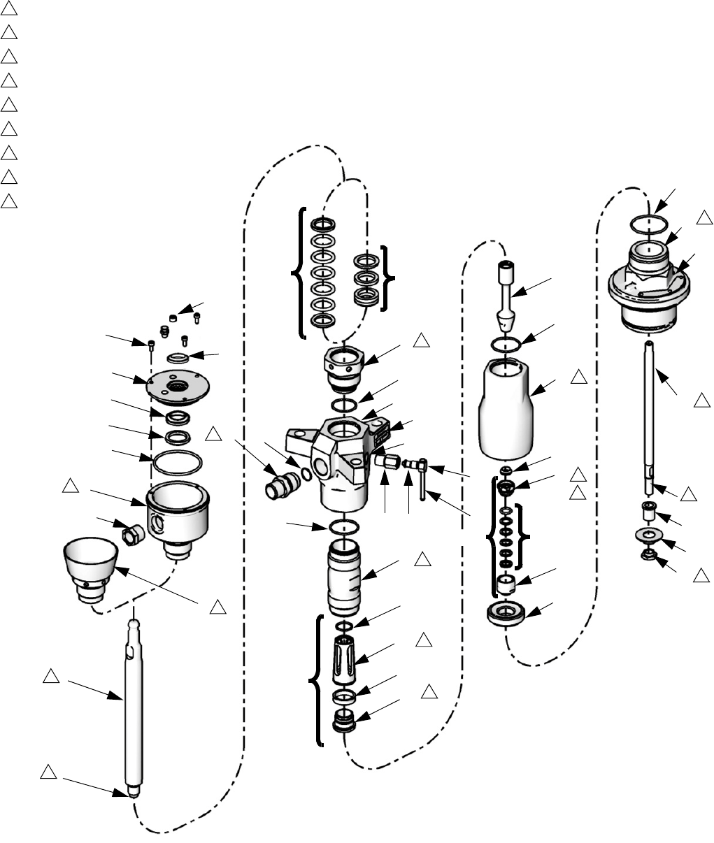
Parts
60cc Displacement Pumps
KEY:
Torque to 85-95 ft-lb (115-128 N•m)
Torque to 28-44 ft-lb (38-59 N•m)
Torque to 213-287 ft-lb (288-387 N•m)
Torque to 43-47 ft-lb (58-63 N•m)
Torque to 34-38 ft-lb (45-51 N•m)
Torque to 26-30 ft-lb (35-41 N•m)
Torque to 90-130 ft-lb (122-173 N•m)
Torque to 44-62 ft-lb (60-84 N•m)
Apply thread sealant
P: Throat Packings
S: Intake Valve Packings
T: Piston Check Valve Assembly (includes 23)
Lubricate all soft seal components before
installation.
1
2
3
4
5
6
7
8
9
21
22
24
23
18
38
33
32
20
4
2
39 40
18
17
29
44
28
31
30
13
14
10
61
16
11
12
9
1
P (5-8)
S (34-37)
42
41
P (5-7)
9
4
5
1
2
3
6
2
8
7
9
9
9
2
9
3
49,
52
43
T
25
26
27
19
15
TI12644B
R (32-37)
48,
49
47, 49
3
3
Parts
312375J 19
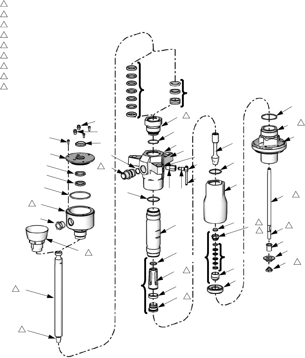
100cc Displacement Pumps
KEY:
Torque to 85-95 ft-lb (115-128 N•m)
Torque to 28-44 ft-lb (38-59 N•m)
Torque to 213-287 ft-lb (288-387 N•m)
Torque to 43-47 ft-lb (58-63 N•m)
Torque to 34-38 ft-lb (45-51 N•m)
Torque to 26-30 ft-lb (35-41 N•m)
Torque to 90-130 ft-lb (122-173 N•m)
Torque to 44-62 ft-lb (60-84 N•m)
Apply thread sealant
L: Piston Check Valve Assembly (includes 23)
M: Throat Packings
N: Intake Valve Packings
Lubricate all soft seal components before
installation.
1
2
3
4
5
6
7
8
9
TI10862A
21
22
24
23
18
38 33
32
20
4
2
39 40
18
17
29
44
28
31
30
13
14
10
15
61
11
12
9
1
P (5-8)
42
41
P (5-7)
9
4
5
1
2
3
6
2
8
7
9
9
9
2
9
3
49,
52
43
48,
25
26
27
19
51
L
16
49
47, 49
R (32-37) S (34-37)
Parts
20 312375J
60cc and 100cc Displacement Pumps
CS Models only.
SS Models only.
CM Models only.
SM Models only.
‡See 60cc and 100cc Kits table on page 21.
Replacement Danger and Warning labels, tags, and
cards are available at no cost.
Ref. Part Description Qty.
1257530 KIT, rod, displacement; chrome
(includes 18, 21); L060 only
1
257531 KIT, rod, displacement; MaxLife
(includes 18, 21); L060 only
1
255569 KIT, rod, displacement; chrome
(includes 18, 21); L100 only
1
255570 KIT, rod, displacement; MaxLife
(includes 18, 21); L100 only
1
2255604 KIT, housing, outlet, (150 mm)
(includes 18, 21, 44, 47, 49, 52)
1
257561 KIT, housing, outlet, (150 mm);
sst (includes 18, 21, 44, 47, 49,
52)
315K751 CARTRIDGE 1
15U603 CARTRIDGE; sst 1
4‡ 104361 O-RING, cartridge 1
5‡ GLAND, packing female; see
60cc and 100cc Packing Kits
1
GLAND, packing, u-cup; see
60cc and 100cc Packing Kits
6‡ V-PACKING; UHMWPE; see
60cc and 100cc Packing Kits
3
SPACER, u-cup; see
60cc and 100cc Packing Kits
1
7‡ V-PACKING; PTFE; see 60cc
and 100cc Packing Kits
2
SPACER, u-cup; acetal; see
60cc and 100cc Packing Kits
1
8‡ GLAND, packing male; see
60cc and 100cc Packing Kits
1
9‡ NUT, packing, open wet cup 1
CUP, wet, enclosed 1
10‡ COVER, wet cup 1
11‡ 161446 O-RING
12‡ SIGHTGLASS 1
13‡ COVER, oil hole 1
14‡ SCREW, socket hd cap; M5 x 12 3
15‡ WIPER, wet cup cover 1
16‡ SEAL, wet cup cover 1
17‡ CYLINDER, pump 1
CYLINDER, pump, MaxLife
18‡ 109205 O-RING 2
19 184044 HOUSING, valve 1
15U586 HOUSING, valve; sst 1
20‡ SEAT, intake 1
21‡ SEAL 1
22 255610 KIT, intake housing, cylinder
(includes 21, 48, 49)
1
257560 KIT, intake housing, cylinder; sst
(includes 21, 48, 49)
1
23‡ SEAT, piston 1
24‡ ROD, piston 1
ROD, piston; MaxLife
25 184122 GUIDE, piston 1
15U598 GUIDE, piston; sst 1
26 184051 PISTON 1
15U597 PISTON; sst 1
27 184121 NUT, shovel 1
15U596 NUT, shovel; sst 1
28 15M518 GUIDE, piston 1
257667 GUIDE, piston; sst 1
29‡ BEARING, guide 1
30‡ SEAT, piston 1
31‡ SEAL, piston 1
32‡ VALVE, intake 1
33‡ NUT, packing 1
34‡ GLAND, male, piston; see
60cc and 100cc Packing Kits
1
35‡ PACKING, UHMWPE; see
60cc and 100cc Packing Kits
2
36‡ PACKING; leather; see
60cc and 100cc Packing Kits
2
PACKING, PTFE; see
60cc and 100cc Packing Kits
2
37‡ GLAND, female, piston; see
60cc and 100cc Packing Kits
1
38‡ SEAL, valve 1
39‡ HOUSING, valve 1
40‡ PLUG, valve 1
41‡ HANDLE, outlet bleed 1
42‡ CLIP, outlet bleed 1
43 184037 FITTING, outlet 1
15U592 FITTING, outlet; sst 1
44‡ 110135 O-RING 1
47184090 LABEL, warning 1
48184151 LABEL, warning 1
49 100508 SCREW, drive 7
50172479 TAG, instruction, safety 1
51‡ PLUG, pipe 1
52‡ 197561 PLATE, identification 1
61‡ RING, retaining 1
Ref. Part Description Qty.

Parts
312375J 21
60cc and 100cc Kits
The following table indicates which parts (according to reference number) are included in each kit.
Kit
Reference Numbers
456789101112131415161718202123242930313233343536373839404142445161
255507
256866
255508
256867
255523
255524
257558
255533
255539
256865
255540
256868
255551
257557
255557
256869
255558
256870
255577
256871
255578
256872
257532
257533
255591
255592
255615
255616
255618
255696
257559
16F205

Parts
22 312375J
Kit Descriptions
Kit Description
255507 Complete Seal Kit; Severe Duty, CS
256866 Complete Seal Kit; Severe Duty, SS
255508 Complete Seal Kit; MaxLife, CM
256867 Complete Seal Kit; MaxLife, SM
255523 Throat Seal Kit; Severe Duty
255524 Throat Seal Kit; MaxLife, CM
257558 Throat Seal Kit; MaxLife, SM
255533 Piston Seal Kit
255539 Intake Kit; Severe Duty, CS
256865 Intake Kit; Severe Duty, SS
255540 Intake Kit; MaxLife, CM
256868 Intake Kit; MaxLife, SM
255551 Piston Seal Metal and Soft Kit CS and CM
257557 Piston Seal Metal and Soft Kit SS and SM
255557 Intake Valve Seal Metal and Soft Kit;
Severe Duty, CS
256869 Intake Valve Seal Metal and Soft Kit;
Severe Duty; SS
255558 Intake Valve Seal Metal and Soft Kit;
MaxLife, CM
256870 Intake Valve Seal Metal and Soft Kit;
MaxLife, SM
255577 Priming Piston Rod Kit; Severe Duty, CS
256871 Priming Piston Rod Kit; Severe Duty, SS
255578 Priming Piston Rod Kit; MaxLife; CM
256872 Priming Piston Rod Kit; MaxLife, SM
255604 Outlet Kit, CS; see page 20 for parts
included in kit
257561 Outlet Kit, SS; see page 20 for parts
included in kit
255610 Intake Cylinder Kit, CS; see page 20 for
parts included in kit
257560 Intake Cylinder Kit, SS; see page 20 for
parts included in kit
255615 Bleed Valve Kit; CS
255616 Bleed Valve Kit; SS
255618 Enclosed Wet Cup Seal Kit; MaxLife
255696 Enclosed Wet Cup Kit; MaxLife, CS
257559 Enclosed Wet Cup Kit; MaxLife, SS
16F205 Complete Seal Kit; PTFE Alternative;
includes all PTFE Alternative kits listed
under 60cc and 100cc Packing Kits,
page 23
60cc Displacement Pumps
257530 Displacement Rod Kit; Severe Duty,
L060CS and L060SS; see page 20 for
parts included in kit
257531 Displacement Rod Kit; MaxLife, L060CM
and L060SM; see page 20 for parts
included in kit
257532 Cylinder Kit; Severe Duty, L060CS and
L060SS
257533 Cylinder Kit; MaxLife, L060CM and
L060SM
100cc Displacement Pumps
255569 Displacement Rod Kit; Severe Duty,
L100CS and L100SS; see page 20 for
parts included in kit
255570 Displacement Rod Kit; MaxLife, CM and
SM; see page 20 for parts included in kit
255591 Cylinder Kit; Severe Duty, L100CS and
L100SS
255592 Cylinder Kit; MaxLife, L100CM and
L100SM
Kit Description

Parts
312375J 23
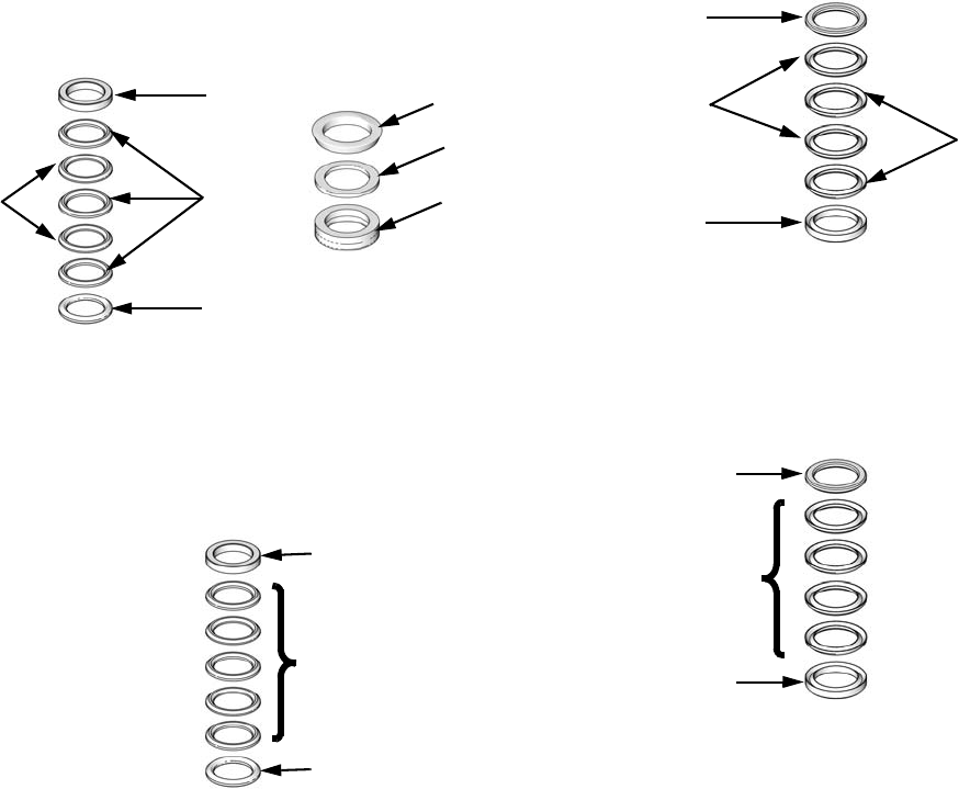
60cc and 100cc Packing Kits
Throat Packings
Severe Duty
MaxLife
PTFE Alternative
Intake Valve Packings
Severe Duty and MaxLife
CS Models only.
SS Models only.
CM Models only.
SM Models only.
PTFE Alternative
Piston Packings
PTFE Alternative
Ref. Description Qty.
5 GLAND, packing female; CST 1
GLAND, packing, female; SST 1
6 V-PACKING; UHMWPE 3
7 V-PACKING; PTFE 2
8 GLAND, packing male; CST 1
GLAND, packing male; SST 1
Ref. Description Qty.
5 SEAL, u-cup 1
6 SPACER, CST 1
SPACER, SST 1
7 SPACER, acetal 1
Ref. Description Qty.
5 GLAND, packing, female 1
6 V-PACKING, PTFE 5
8 GLAND, packing, male 1
ti10589a
5
8
6
7
ti10592a
6
5
Severe Duty MaxLife
7
* Lips face down
* Lips face down
ti10590a
5
8
6
* Lips face down
Ref. Description Qty.
34 GLAND, male, priming piston; CST 1
GLAND, male, priming piston; SST 1
35 PACKING; UHMWPE 2
36 PACKING; PTFE 2
PACKING; leather 2
37 GLAND, female, priming piston; CST 1
GLAND, female, priming piston; SST
Ref. Description Qty.
34 GLAND, male, priming piston 1
35 PACKING, PTFE 4
37 GLAND, female, priming piston 1
Ref. Description Qty.
31 SEAL, piston 1
ti10595a
34
35
36
37
* Lips face up
ti10596a
34
35
37
* Lips face up
Parts
24 312375J
200cc and 250cc Displacement Pumps
KEY:
Torque to 239-271 ft-lb (323-366 N•m)
Torque to 95-115 ft-lb (128-155 N•m)
Torque to 345-435 ft-lb (466-587 N•m)
Torque to 71-79 ft-lb (96-107 N•m)
Torque to 92-102 ft-lb (124-138 N•m)
Torque to 57-63 ft-lb (77-85 N•m)
Torque to 130-190 ft-lb (176-258 N•m)
Apply thread sealant
L: Piston Check Valve Assembly
M: Throat Packings
N: Intake Valve Packings
Lubricate all soft seal components before
installation.
1
2
3
4
5
6
7
8
4
5
1
2
3
TI10863B
21
22
24
23
18
38 33
32
20
4
2
39 40
18
17
29
28
31
30
13
14
10
15
16
11
12
9
1
P (5-8)
S
42
41
9
(34-37)
6
2
26
27
6
19
3
47, 49
7
8
47, 49
49, 52
51
200cc Displacement Pump Shown
T
T (cont.)
60 8
P (5-7)
Parts
312375J 25
200cc Displacement Pumps
Model L200CS only.
Model L200CM only.
Model L200SS only.
Model L200SM only.
‡See L200cc Kits table, page 26.
Replacement Danger and Warning labels, tags, and
cards are available at no cost.
Ref. Part Description Qty.
1255571 KIT, rod, displacement; chrome
(includes 18, 21)
1
255572 KIT, rod, displacement; MaxLife
(includes 18, 21)
1
2255605 KIT, outlet, housing (includes 18,
21, 47, 49, 52)
1
255606 KIT, outlet, housing; SST
(includes 18, 21, 47, 49, 52)
1
3189641 CARTRIDGE 1
189645 CARTRIDGE; SST 1
4‡ 166073 O-RING 1
5‡ GLAND, packing female; see
L200cc Packing Kits
1
GLAND, packing, u-cup; see
L200cc Packing Kits
1
6‡ V-PACKING; PTFE; see L200cc
Packing Kits
2
SPACER, u-cup; see L200cc
Packing Kits
1
7‡ V-PACKING; UHMWPE; see
L200cc Packing Kits
3
SPACER, u-cup, bearing; see
L200cc Packing Kits
1
8‡ GLAND, packing male; see
L200cc Packing Kits
1
9‡ NUT, packing, open 1
NUT, packing, open; SST 1
CUP, wet, enclosed 1
CUP, wet, enclosed, SST 1
10‡ COVER, wet cup 1
11‡ 104095 O-RING
12‡ SIGHTGLASS 1
13‡ COVER, oil hole 1
14‡ SCREW, socket hd cap; M5 x 12 3
15‡ WIPER, wet cup cover 1
16‡ SEAL, wet cup cover 1
17‡ CYLINDER, pump, Severe Duty 1
CYLINDER, pump, MaxLife 1
18‡ 109499 O-RING 2
19 189442 HOUSING, valve 1
189512 HOUSING, valve; SST 1
20‡ SEAT, valve 1
21 189492 SEAL 1
22 255611 KIT, intake housing
(includes 21, 47)
1
255612 KIT, intake housing; SST
(includes 21, 47)
1
23‡ SEAT, piston 1
24‡ ROD, piston; Severe Duty 1
ROD, piston; MaxLife 1
26 276378 PISTON 1
27 190241 SEAT, piston 1
28‡ 15M520 GUIDE, piston 1
15M654 GUIDE, piston; SST 1
29‡ BEARING, guide 1
30‡ SEAT, piston 1
31‡ SEAL, piston; see L200cc Pack-
ing Kits
1
32‡ VALVE, intake 1
33‡ NUT, packing 1
NUT, packing; SST 1
34‡ GLAND, male, piston; see
L200cc Packing Kits
1
GLAND, male, piston; SST; see
L200cc Packing Kits
1
35‡ V-PACKING; see L200cc Pack-
ing Kits
2
36‡ V-PACKING; see L200cc Pack-
ing Kits
2
V-PACKING; see L200cc Pack-
ing Kits
2
37‡ GLAND, female; see L200cc
Packing Kits
1
GLAND, female, piston; SST;
see L200cc Packing Kits
1
38‡ SEAL, valve 1
39‡ HOUSING, valve 1
HOUSING, valve; SST 1
40‡ PLUG, valve 1
PLUG, valve; SST 1
41‡ HANDLE, outlet bleed 1
42‡ CLIP, outlet bleed 1
47184090 LABEL, warning 2
184462
49 100508 SCREW, drive 6
109202
50172479 TAG, instruction, safety 1
51 PLUG, pipe 1
52 197561 PLATE, identification 1
60 PLUG, pipe 1
Ref. Part Description Qty.

Parts
26 312375J
L200cc Kits
The following table indicates which parts (according to reference number) are included in each kit.
Kit
Reference Numbers
4567891011121314151617182021232429303132333435363738394041425160
255509
255510
255511
255512
255525
255526
255527
255534
255541
255542
255552
255559
255560
255579
255580
255581
255582
255593
255594
255615
255616
255619
255622
255623
255625
255626
255693
255697
255700

Parts
312375J 27
L200cc Kit Descriptions
Kit Description
255509 Complete Seal Kit, L200CS
255510 Complete Seal Kit, L200CM
255511 Complete Seal Kit, L200SS
255512 Complete Seal Kit, L200SM
255525 Throat Seal Kit, L200CS
255526 Throat Seal Kit, L200SS
255527 Throat Seal Kit, L200CM and L200SM
255534 Piston Kit
255541 Intake Soft Seal Kit, L200CS
255622 Intake Soft Seal Kit, L200CM
255542 Intake Soft Seal Kit, L200SS
255623 Intake Soft Seal Kit, L200SM
255552 Piston Seal Metal and Soft Kit
255559 Intake Valve Seal Metal and Soft Kit;
Severe Duty, L200CS
255625 Intake Valve Seal Metal and Soft Kit;
MaxLife, L200CM
255560 Intake Valve Seal Metal and Soft Kit;
Severe Duty, L200SS
255626 Intake Valve Seal Metal and Soft Kit;
MaxLife, L200SM
255571 Displacement Rod Kit, L200CS and
L200SS; see 25 for parts included in kit
255572 Displacement Rod Kit, L200CM and
L200SM; see 25 for parts included in kit
255579 Priming Piston Rod Kit; L200CS
255580 Priming Piston Rod Kit; L200CM
255581 Priming Piston Rod Kit; L200SS
255582 Priming Piston Rod Kit; L200SM
255593 Cylinder Kit; L200CS, L200SS
255594 Cylinder Kit; L200CM, L200CS
255605 Outlet Kit; Carbon models; see 25 for
parts included in kit
255606 Outlet Kit; SST models; see 25 for parts
included in kit
255611 Intake Housing Kit; Carbon models; see
25 for parts included in kit
255612 Intake Housing Kit; SST models; see 25
for parts included in kit
255615 Bleed Valve Kit, all Carbon models
255616 Bleed Valve Kit, all SST models
255619 Enclosed Wet Cup Seal Kit; MaxLife,
L200CM and L200SM
255693 Complete Seal Kit; PTFE Alternative;
includes all PTFE Alternative kits listed
under L200cc Packing Kits, page 28
255697 Enclosed Wet Cup Kit; L200CM
255700 Enclosed Wet Cup Kit; L200SM
Kit Description
Parts
28 312375J
L200cc Packing Kits
Throat Packings
Severe Duty
MaxLife
PTFE Alternative
Intake Valve Packings
Severe Duty and MaxLife
Model L200CS only.
Model L200CM only.
Model L200SS only.
Model L200SM only.
PTFE Alternative
Piston Packings
PTFE Alternative
Ref. Description Qty.
5GLAND, packing female 1
GLAND, SST 1
6 V-PACKING; UHMWPE 3
7 V-PACKING; PTFE 2
8GLAND, packing, male 1
GLAND, packing, male; SST 1
Ref. Description Qty.
5 SEAL, u-cup 1
6SPACER, metal 1
7 SPACER, acetal 1
Ref. Description Qty.
5 GLAND, packing, female 1
6 V-PACKING, PTFE 5
8 GLAND, packing, male 1
ti10590a
5
8
6
7
ti10593a
6
5
Severe Duty MaxLife
7
* Lips face down * Lips face down
ti10590a
5
8
6
* Lips face down
Ref. Description Qty.
34 GLAND, male, priming piston 1
GLAND, male, priming piston;
SST
1
35 PACKING; UHMWPE 2
36 PACKING; PTFE (Severe Duty) 2
PACKING; leather (MaxLife) 2
37 GLAND, female, priming piston 1
GLAND, female, priming pis-
ton; SST
1
Ref. Description Qty.
34 GLAND, male, priming piston 1
35 PACKING, PTFE 4
37 GLAND, female, priming piston 1
Ref. Description Qty.
31 SEAL, piston 1
ti10596a
34
35
36
37
* Lips face up
ti10596a
34
35
37
* Lips face up
Parts
312375J 29
250cc Displacement Pumps
Model L250CS only.
Model L250CM only.
Model L250SS only.
Model L250SM only.
‡See L250cc Kits table, page 30.
Replacement Danger and Warning labels, tags, and
cards are available at no cost.
Ref. Part Description Qty.
1255573 KIT, rod, displacement;
chrome (includes 18, 21)
1
255574 KIT, rod, displacement;
MaxLife (includes 18, 21)
1
2255605 KIT, outlet, housing
(includes 18, 21, 47, 49, 52)
1
255606 KIT, outlet, housing, SST
(includes 18, 21, 47, 49, 52)
1
3189641 CARTRIDGE 1
189645 CARTRIDGE; SST 1
4‡ 166073 O-RING 1
5‡ GLAND, packing female; see
L250cc Packing Kits
1
GLAND, packing, u-cup; see
L250cc Packing Kits
1
6‡ V-PACKING; PTFE; see
L250cc Packing Kits
2
SPACER, u-cup; see L250cc
Packing Kits
1
7‡ V-PACKING; UHMWPE; see
L250cc Packing Kits
3
SPACER, acetal; see L250cc
Packing Kits
1
8‡ GLAND, packing male; see
L250cc Packing Kits
1
9‡ NUT, packing, open 1
CUP, wet, enclosed
CUP, wet; SST 1
10‡ COVER, wet cup 1
11‡ 104095 O-RING 1
12‡ SIGHTGLASS 1
13‡ COVER, oil hole 1
14‡ SCREW, socket hd cap; M5 x
12
3
15‡ WIPER, wet cup cover 1
16‡ SEAL, wet cup cover 1
17‡ CYLINDER, pump 1
CYLINDER, pump, MaxLife 1
18‡ 109499 O-RING 2
19 190389 HOUSING, valve 1
190390 HOUSING, valve; SST 1
20‡ SEAT, valve 1
21‡ 189492 SEAL, 1
22 255611 KIT, intake housing
(includes 21, 47)
1
255612 KIT, intake housing; SST
(includes 21, 47)
1
23‡ SEAT, piston 1
24‡ ROD, piston 1
ROD, piston; MaxLife 1
26 276378 PISTON 1
27 190241 SEAT, piston 1
28‡ 15M655 GUIDE, piston 1
15M523 GUIDE, piston; SST 1
29‡ BEARING, guide 1
30‡ SEAT, piston 1
31‡ SEAL, piston 1
32‡ VALVE, intake 1
33‡ NUT, packing 1
NUT, packing; SST 1
34‡ GLAND, male, piston; SST;
see L250cc Packing Kits
1
35‡ V-PACKING; see L250cc
Packing Kits
2
36‡ V-PACKING; PTFE; see
L250cc Packing Kits
2
V-PACKING; leather; see
L250cc Packing Kits
2
37‡ GLAND, female, piston; see
L250cc Packing Kits
1
38‡ SEAL, valve 1
39‡ HOUSING, valve 1
HOUSING, valve; SST 1
40‡ PLUG, valve 1
PLUG, valve; SST 1
41‡ HANDLE, outlet bleed 1
42‡ CLIP, outlet bleed 1
47184090 LABEL, warning 2
184462 LABEL, warning 2
49 100508 SCREW, drive 6
109202 SCREW, drive 6
50172479 TAG, instruction, safety 1
51 PLUG, pipe 1
52 197561 PLATE, identification 1
60 PLUG, pipe 1
Ref. Part Description Qty.

Parts
30 312375J
L250cc Kits
The following table indicates which parts (according to reference number) are included in each kit.
Kit
Reference Numbers
4 5 6 7 8 9 1011121314151617182021232429303132333435363738394041425160
255513
255514
255515
255516
255528
255529
255530
255536
255543
255544
255545
255546
255554
255561
255562
255563
255564
255583
255584
255585
255586
255597
255598
255615
255616
255620
255694
255698
255701

Parts
312375J 31
L250cc Kit Descriptions
Kit Description
255513 Complete Seal Kit, L250CS
255514 Complete Seal Kit, L250CM
255515 Complete Seal Kit, L250SS
255516 Complete Seal Kit, L250SM
255528 Throat Seal Kit, L250CS
255529 Throat Seal Kit, L250SS
255530 Throat Seal Kit, L250CM and L250SM
255536 Piston Kit
255543 Intake Soft Seal Kit, L250CS
255544 Intake Soft Seal Kit, L250CM
255545 Intake Soft Seal Kit, L250SS
255546 Intake Soft Seal Kit, L250SM
255554 Piston Seal Metal and Soft Kit
255561 Intake Valve Seal Metal and Soft Kit;
L250CS
255562 Intake Valve Seal Metal and Soft Kit;
L250CM
255563 Intake Valve Seal Metal and Soft Kit;
L250SS
255564 Intake Valve Seal Metal and Soft Kit;
L250SM
255573 Displacement Rod Kit, L250CS and
L250SS
255574 Displacement Rod Kit, L250CM and
L250SM
255583 Priming Piston Rod Kit; L250CS
255584 Priming Piston Rod Kit; L250CM
255585 Priming Piston Rod Kit; L250SS
255586 Priming Piston Rod Kit; L250SM
255597 Cylinder Kit; L250CS and L250SS
255598 Cylinder Kit; L250CM and L250SM
255605 Outlet Kit; Carbon models
255606 Outlet Kit; SST models
255611 Intake Housing Kit; Carbon models
255612 Intake Housing Kit; SST models
255615 Bleed Valve Kit, all Carbon models
255616 Bleed Valve Kit, all SST models
255620 Enclosed Wet Cup Seal Kit; MaxLife,
L250CM and L250SM
255694 Complete Seal Kit; PTFE Alternative;
includes all PTFE alternative kits listed
under L250cc Packing Kits, page 32.
255698 Enclosed Wet Cup Kit; L250CM
255701 Enclosed Wet Cup Kit; L250SM
Kit Description

Parts
32 312375J
L250cc Packing Kits
Throat Packings
Severe Duty
MaxLife
PTFE Alternative
Intake Valve Packings
Severe Duty and MaxLife
Model L250CS only.
Model L250CM only.
Model L250SS only.
Model L250SM only.
PTFE Alternative
Piston Packings
PTFE Alternative
Ref. Description Qty.
5GLAND, packing, female 1
GLAND, packing, female; SST 1
6 V-PACKING; UHMWPE 3
7V-PACKING; PTFE 2
8GLAND, packing, male 1
GLAND, packing, male; SST 1
Ref. Description Qty.
5 SEAL, u-cup 1
6 SPACER, metal 1
7 SPACER, acetal 1
Ref. Description Qty.
5 GLAND, packing, female 1
6 V-PACKING, PTFE 5
8 GLAND, packing, male 1
ti10590a
5
8
6
7
ti10593a
6
5
Severe Duty MaxLife
7
* Lips face down
* Lips face down
ti10590a
5
8
6
* Lips face down
Ref. Description Qty.
34 GLAND, male, priming piston; SST 1
35 PACKING; UHMWPE 2
36 PACKING; PTFE (Severe Duty) 2
PACKING; leather (MaxLife) 2
37 GLAND, female, priming piston 1
Ref. Description Qty.
34 GLAND, male, priming piston 1
35 PACKING, PTFE 4
37 GLAND, female, priming piston 1
Ref. Description Qty.
31 SEAL, piston 1
ti10596a
34
35
36
37
* Lips face up
ti10596a
34
35
37
* Lips face up

Parts
312375J 33
Parts
34 312375J
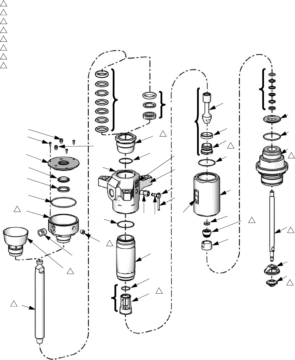
500cc Displacement Pumps
KEY:
Torque to 327-363 ft-lb (441-490 N•m)
Torque to 95-115 ft-lb (128-155 N•m)
Torque to 90-100 ft-lb (122-135 N•m)
Torque to 71-78 ft-lb (96-106 N•m)
Torque to 149-261 ft-lb (203-355 N•m)
Torque to 160-220 ft-lb (217-299 N•m)
Torque to 104-136 ft-lb (141-185 N•m)
Apply thread sealant
L: Piston Check Valve Assembly
M: Throat Packings
N: Intake Valve Packings
Lubricate all soft seal components before
installation.
1
2
3
4
6
7
8
9
4
3
1
2
TI10864B
22
24
23
18
38
33
32
20
4
2
39 40
18
17
18
28
31
30
13
14
10
15
16
11
12
9
1
P (5-8)
S
42
41
P (5-7)
9
(34-37)
3
2
26
27
4
19
3
6
7
47, 49
49, 52
51
45
46
43 44
8
29
25
T
T (cont.)
R
(32-37)
60
48,
49
9
Parts
312375J 35
L500cc Models
Model L500CS only.
Model L500CM only.
Model L500SS only.
Model L500SM only.
‡See L500cc Kits table, page 36.
Replacement Danger and Warning labels, tags, and
cards are available at no cost.
Ref. Part Description Qty.
1255575 KIT, rod, displacement; chrome
(includes 18)
1
255576 KIT, rod, displacement; MaxLife
(includes 18)
1
2255607 KIT, outlet, housing
(includes 18, 44, 47, 49, 52)
1
255609 KIT, outlet, housing
(includes 18, 44, 47, 49, 52)
1
315K752 CARTRIDGE 1
15M634 CARTRIDGE; SST 1
4‡ 102857 O-RING 1
5‡ GLAND, packing female; see
L500cc Packing Kits
1
GLAND, packing, u-cup; see
L500cc Packing Kits
1
6‡ V-PACKING; PTFE; see L500cc
Packing Kits
2
SPACER, u-cup; see L500cc
Packing Kits
1
7‡ V-PACKING; UHMWPE; see
L500cc Packing Kits
3
SPACER; acetal; see L500cc
Packing Kits
1
8‡ GLAND, packing male; see
L500cc Packing Kits
1
9‡ NUT, packing, open 1
CUP, wet, enclosed 1
10‡ COVER, wet cup 1
11‡ 104095 O-RING
12‡ SIGHTGLASS 1
13‡ COVER, oil hole 1
14‡ SCREW, socket hd cap; M5 x 12 3
15‡ WIPER, wet cup cover 1
16‡ SEAL, wet cup cover 1
17‡ CYLINDER, pump 1
CYLINDER, pump, MaxLife 1
18‡ 184072 O-RING 3
19 184415 HOUSING, valve 1
20‡ SEAT, valve 1
SEAT, valve; SST 1
22 255613 KIT, intake housing (includes 48) 1
255614 KIT, intake housing; SST
(includes 48)
1
23‡ SEAT, piston 1
24‡ ROD, piston 1
ROD, piston; MaxLife 1
25 189988 GUIDE, piston, SST 1
26 190276 PISTON 1
190277 PISTON; SST 1
27 112733 SEAT, piston 1
112734 SEAT, piston; SST 1
28‡ 15M525 GUIDE, piston 1
29‡ BEARING, guide 1
30‡ SEAT, piston 1
31‡ SEAL, piston; see L500cc Pack-
ing Kits
1
32‡ VALVE, intake 1
VALVE, intake; SST 1
33‡ NUT, packing 1
NUT, packing; SST 1
34‡ GLAND, male, piston; SST;
see L500cc Packing Kits
1
35‡ V-PACKING; see L500cc Pack-
ing Kits
2
36‡ V-PACKING; see L500cc Pack-
ing Kits
2
V-PACKING; see L500cc Pack-
ing Kits
2
37‡ GLAND, female, piston; SST;
see L500cc Packing Kits
1
38‡ SEAL, valve 1
39‡ HOUSING, valve 1
HOUSING, valve; SST 1
40‡ PLUG, valve 1
PLUG, valve; SST 1
41‡ HANDLE, outlet bleed 1
42‡ CLIP, outlet bleed 1
43 184279 FITTING, outlet 1
184387 FITTING, outlet; SST 1
44‡ 109213 SEAL, outlet 1
45 109203 BOLT, hex 6
109470 BOLT, hex; SST 6
46 184618 WASHER, split 6
47184293 LABEL, warning 1
184462 LABEL, warning 1
49 100508 SCREW, drive 6
109202 SCREW, drive; SST 6
50172479 TAG, instruction, safety 1
51 PLUG, pipe 1
52 197561 PLATE, identification 1
60 PLUG, pipe 1
Ref. Part Description Qty.

Parts
36 312375J
L500cc Kits
The following table indicates which parts (according to reference number) are included in each kit.
Kit
Reference Numbers
4567891011121314151617182023242930313233343536373839404142445160
255517
255518
255519
255520
255531
255532
255538
255547
255548
255549
255550
255556
255565
255566
255567
255568
255587
255588
255589
255590
255601
255602
255615
255616
255621
255695
255699
255702

Parts
312375J 37
L500cc Kit Descriptions
Kit Description
255517 Complete Seal Kit, L500CS
255518 Complete Seal Kit, L500CM
255519 Complete Seal Kit, L500SS
255520 Complete Seal Kit, L500SM
255531 Throat Seal Kit, L500CS and L500SS
255532 Throat Seal Kit, L500CM and L500SM
255538 Piston Soft Seal Kit
255547 Intake Soft Seal Kit, L500CS
255548 Intake Soft Seal Kit, L500CM
255549 Intake Soft Seal Kit, L500SS
255550 Intake Soft Seal Kit, L500SM
255556 Piston Seal Metal and Soft Kit
255565 Intake Valve Seal Metal and Soft Kit;
Severe Duty, L500CS
255566 Intake Valve Seal Metal and Soft Kit;
MaxLife, L500CM
255567 Intake Valve Seal Metal and Soft Kit;
Severe Duty, L500SS
255568 Intake Valve Seal Metal and Soft Kit;
MaxLife, L500SM
255575 Displacement Rod Kit, L500CS and
L500SS
255576 Displacement Rod Kit, L500CM and
L500SM
255587 Priming Piston Rod Kit; L500CS
255588 Priming Piston Rod Kit; L500CM
255589 Priming Piston Rod Kit; L500SS
255590 Priming Piston Rod Kit; L500SM
255601 Cylinder Kit; Severe Duty, L500CS and
L500SS
255602 Cylinder Kit; MaxLife, L500CM and
L500SM
255607 Outlet Kit; Carbon, L500CS and L500CM
255609 Outlet Kit; SST, L500SM and L500SS
255613 Intake Housing Kit; Carbon models
255614 Intake Housing Kit; SST models
255615 Bleed Valve Kit, all Carbon models
255616 Bleed Valve Kit, all SST models
255621 Enclosed Wet Cup Seal Kit; MaxLife,
L500CM and L500SM
255695 Complete Seal Kit; PTFE Alternative;
includes all PTFE alternative kits listed
under L500cc Packing Kits, page 38.
255699 Enclosed Wet Cup Kit; L500CM
255702 Enclosed Wet Cup Kit; L500SM
Kit Description

Parts
38 312375J
L500cc Packing Kits
Throat Packings
Severe Duty
MaxLife
PTFE Alternative
Intake Valve Packings
Severe Duty and MaxLife
Model L500CS only.
Model L500CM only.
Model L500SS only.
Model L500SM only.
PTFE Alternative
Piston Packings
PTFE Alternative
Ref. Description Qty.
5 GLAND, packing female 1
6 V-PACKING; UHMWPE 3
7 V-PACKING; PTFE 2
8 GLAND, packing male 1
Ref. Description Qty.
5SEAL, u-cup 1
6 SPACER, metal 1
7 SPACER, acetal 1
Ref. Description Qty.
5 GLAND, packing, female 1
6 V-PACKING, PTFE 5
8 GLAND, packing, male 1
ti10591a
5
8
6
7
ti10594a
6
5
S
evere
D
u
t
y
M
ax
Lif
e
7
* Lips face down
* Lips face down
ti10591a
5
8
6
* Lips face down
Ref. Description Qty.
34 GLAND, male, priming piston 1
35 PACKING; UHMWPE 2
36 PACKING; PTFE (Severe Duty) 2
PACKING; leather (MaxLife) 2
37 GLAND, female, priming piston 1
Ref. Description Qty.
34 GLAND, male, priming piston 1
35 PACKING, PTFE 4
37 GLAND, female, priming piston 1
Ref. Description Qty.
31 SEAl, piston 1
ti10597a
34
35
36
37
* Lips face up
ti11119a
34
35
37
* Lips face up
Dimensions
312375J 39
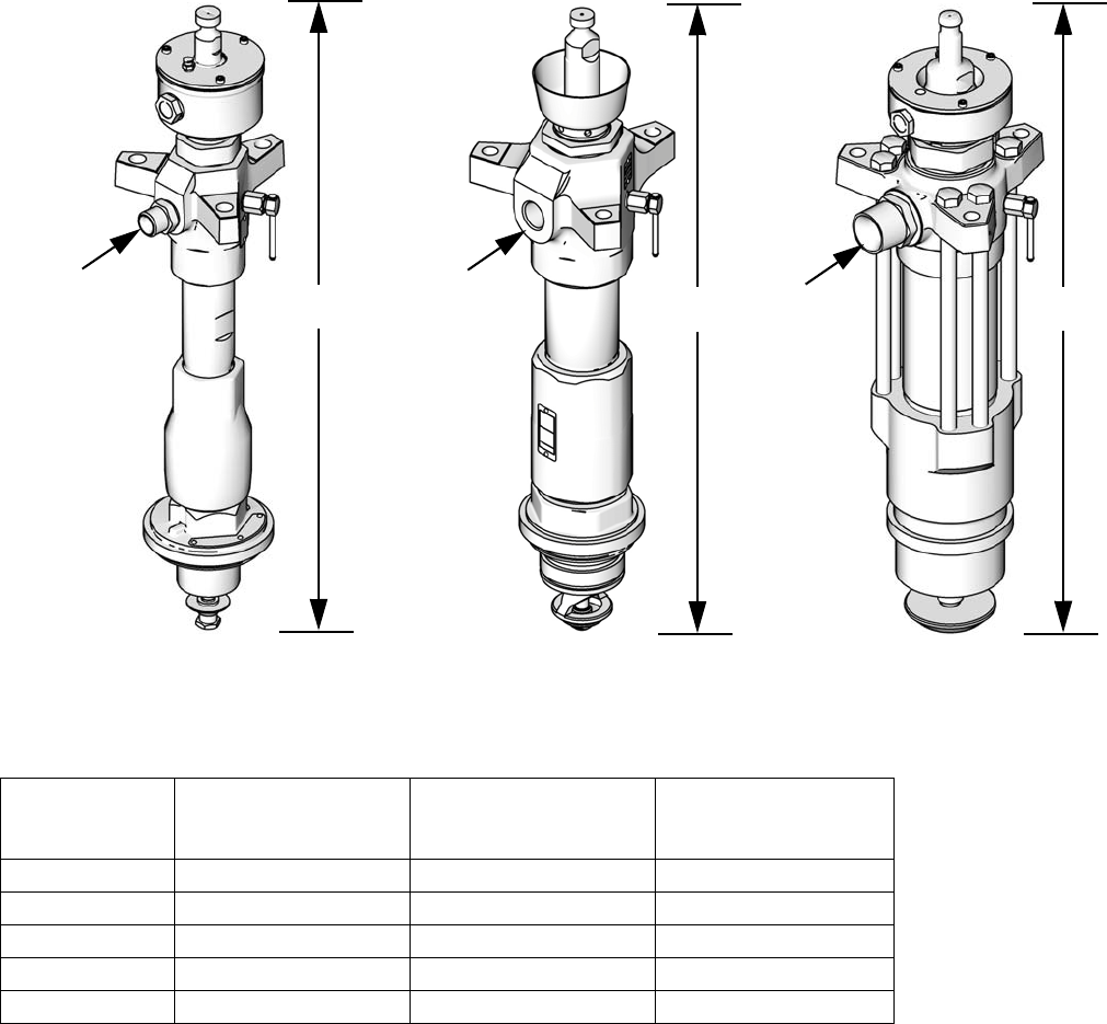
Dimensions
Displacement Pump Dimensions
L200SM and L250SM Models L500CM Model
L060CM and L100CM Models
AAA
C
CC
ti10392a ti10720a ti10396a
Displacement
Pump
A
(Height)
in. (mm)
C
(Outlet Size)
in. npt
Weight
lbs (kg)
60cc 27.2 (691.0) 3/4 npt(m) 34 (15.5)
100cc 28.62 (727.0) 3/4 npt(m) 35 (16)
200cc 29.75 (755.7) 1 npt(f) 64 (29)
250cc 29.68 (754.0) 1 npt(f) 64 (29)
500cc 29.88 (759.0) 1-1/2 npt(m) 86 (39)
Outlet Housing Mounting Hole Layout
40 312375J
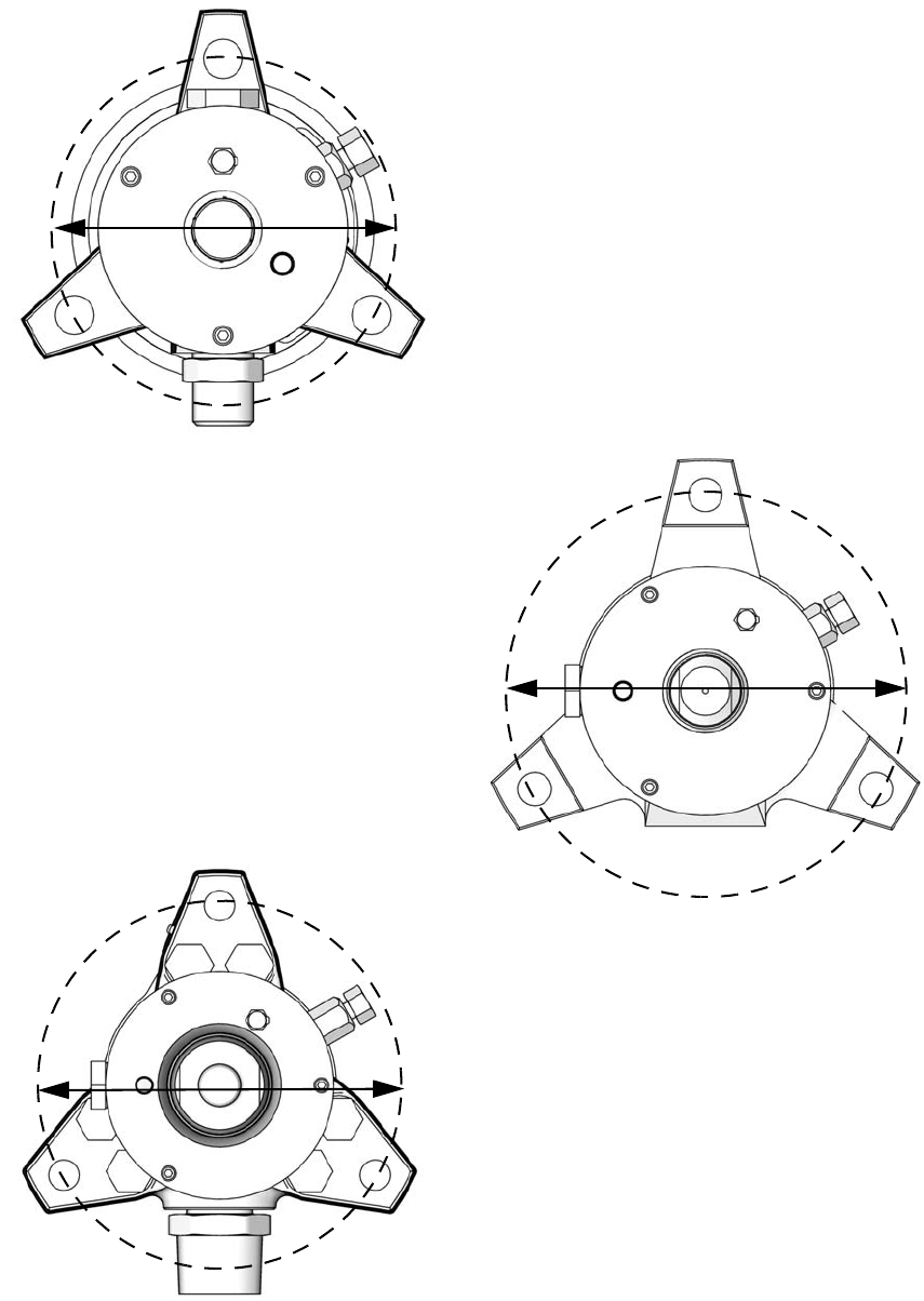
Outlet Housing Mounting Hole Layout
L060cc and L100cc Displacement Pumps
L500cc Displacement Pumps
L200cc and L250cc Displacement Pumps
5.91 in. (150 mm)
8.0 in. (203 mm)
8.0 in. (203 mm)
ti10598a
ti10599a
ti10600a

Outlet Housing Mounting Hole Layout
312375J 41

Technical Data
42 312375J
Technical Data
All displacement pump models have the same maximum operating temperature.
Displacement
Pump Maximum Fluid Working Pressure Displacement per Cycle
60cc 6100 psi (42 MPa, 421 bar) 60cc
100cc 6300 psi (44.1 MPa, 441 bar) 100cc
200cc 6200 psi (43.4 MPa, 434 bar) 200cc
250cc 6200 psi (43.4 MPa, 434 bar) 250cc
500cc 3900 psi (27.3 MPa, 273 bar) 500cc
Maximum operating temperature . . . . . . . . . . . . . . . . . . . 180° F (80° C)
Stroke length . . . . . . . . . . . . . . . . . . . . . . . . . . . . . . . . . .
See next page for wetted parts.
NXT2200, NXT3400, and NXT6500 NXT air motors:
4.75 in. (120 mm)
NXT200, NXT400, NXT700, NXT1200, and NXT1800 air
motors: 2.5 in. (63 mm)
Technical Data
312375J 43
Wetted parts:
L060CS, L060CM, L100CS, L100CM . . . . . . . . . . . .
L060SS and L060SM. . . . . . . . . . . . . . . . . . . . . . . . .
L100SS and L100SM. . . . . . . . . . . . . . . . . . . . . . . . .
L200CS, L200CM, L250CS, L250CM . . . . . . . . . . . .
L200SS and L200SM. . . . . . . . . . . . . . . . . . . . . . . . .
L250SS and L250SM. . . . . . . . . . . . . . . . . . . . . . . . .
L500CS and L500CM . . . . . . . . . . . . . . . . . . . . . . . .
L500SS and L500SM. . . . . . . . . . . . . . . . . . . . . . . . .
E52100, 41L40, and 4140 Alloy Steel; 304, 316, and 17-4
PH Grades of Stainless Steel; Acetal; Carbon-filled PTFE;
Carbon Steel; Ductile Iron; Nickel and Zinc Plating;
Leather; PTFE; Ultra-High Molecular Weight Polyethyl-
ene; Leather
304, 316, and 17-4 PH Grades of Stainless Steel; Acetal;
Leather; PTFE; Ultra-High Molecular Weight Polyethyl-
ene; Leather; PTFE Epoxy Resin
304, 316, and 17-4 PH Grades of Stainless Steel; Acetal;
Leather; PTFE; Ultra-High Molecular Weight Polyethyl-
ene; Leather; PTFE Epoxy Resin
304, 316, 440, and 17-4 PH Grades of Stainless Steel;
Acetal; Alloy Steel; Carbon-filled PTFE; Carbon Steel;
Chrome, Zinc, and Nickel Plating; Ductile Iron;
Glass-Filled PTFE; Leather; PTFE; Ultra-High Molecular
Weight Polyethylene
304, 316, 440, 440C, and 17-4 PH Grades of Stainless
Steel; Acetal; Carbon-filled PTFE; Chrome; Glass-Filled
PTFE; Leather; PTFE; Ultra-High Molecular Weight Poly-
ethylene
304, 316, 440, 440C, PH 13-8 MO, and 17-4 PH Grades
of Stainless Steel; Acetal; Carbon-filled PTFE; Chrome;
Glass-Filled PTFE; Leather; PTFE; Ultra-High Molecular
Weight Polyethylene
304 and 17-4 PH Grades of Stainless Steel; E52100 Alloy
Steel; Acetal; Carbon-filled PTFE; Carbon Steel; Chrome;
Ductile Iron; Leather; PTFE; Ultra-High Molecular Weight
Polyethylene
304, PH 13-8 MO, and 17-4 PH Grades of Stainless Steel;
Acetal; Carbon-filled PTFE; Leather; PTFE; Ultra-High
Molecular Weight Polyethylene

All written and visual data contained in this document reflects the latest product information available at the time of publication.
Graco reserves the right to make changes at any time without notice.
For patent information, see www.graco.com/patents.
Original instructions. This manual contains English. MM 312375
Graco Headquarters: Minneapolis
International Offices: Belgium, China, Japan, Korea
GRACO INC. AND SUBSIDIARIES • P.O. BOX 1441 • MINNEAPOLIS MN 55440-1441 • USA
Copyright 2007, Graco Inc. All Graco manufacturing locations are registered to ISO 9001.
www.graco.com
Revised November 2013
Graco Standard Warranty
Graco warrants all equipment referenced in this document which is manufactured by Graco and bearing its name to be free from defects in
material and workmanship on the date of sale to the original purchaser for use. With the exception of any special, extended, or limited warranty
published by Graco, Graco will, for a period of twelve months from the date of sale, repair or replace any part of the equipment determined by
Graco to be defective. This warranty applies only when the equipment is installed, operated and maintained in accordance with Graco’s written
recommendations.
This warranty does not cover, and Graco shall not be liable for general wear and tear, or any malfunction, damage or wear caused by faulty
installation, misapplication, abrasion, corrosion, inadequate or improper maintenance, negligence, accident, tampering, or substitution of
non-Graco component parts. Nor shall Graco be liable for malfunction, damage or wear caused by the incompatibility of Graco equipment with
structures, accessories, equipment or materials not supplied by Graco, or the improper design, manufacture, installation, operation or
maintenance of structures, accessories, equipment or materials not supplied by Graco.
This warranty is conditioned upon the prepaid return of the equipment claimed to be defective to an authorized Graco distributor for verification of
the claimed defect. If the claimed defect is verified, Graco will repair or replace free of charge any defective parts. The equipment will be returned
to the original purchaser transportation prepaid. If inspection of the equipment does not disclose any defect in material or workmanship, repairs will
be made at a reasonable charge, which charges may include the costs of parts, labor, and transportation.
THIS WARRANTY IS EXCLUSIVE, AND IS IN LIEU OF ANY OTHER WARRANTIES, EXPRESS OR IMPLIED, INCLUDING BUT NOT LIMITED
TO WARRANTY OF MERCHANTABILITY OR WARRANTY OF FITNESS FOR A PARTICULAR PURPOSE.
Graco’s sole obligation and buyer’s sole remedy for any breach of warranty shall be as set forth above. The buyer agrees that no other remedy
(including, but not limited to, incidental or consequential damages for lost profits, lost sales, injury to person or property, or any other incidental or
consequential loss) shall be available. Any action for breach of warranty must be brought within two (2) years of the date of sale.
GRACO MAKES NO WARRANTY, AND DISCLAIMS ALL IMPLIED WARRANTIES OF MERCHANTABILITY AND FITNESS FOR A
PARTICULAR PURPOSE, IN CONNECTION WITH ACCESSORIES, EQUIPMENT, MATERIALS OR COMPONENTS SOLD BUT NOT
MANUFACTURED BY GRACO. These items sold, but not manufactured by Graco (such as electric motors, switches, hose, etc.), are subject to
the warranty, if any, of their manufacturer. Graco will provide purchaser with reasonable assistance in making any claim for breach of these
warranties.
In no event will Graco be liable for indirect, incidental, special or consequential damages resulting from Graco supplying equipment hereunder, or
the furnishing, performance, or use of any products or other goods sold hereto, whether due to a breach of contract, breach of warranty, the
negligence of Graco, or otherwise.
FOR GRACO CANADA CUSTOMERS
The Parties acknowledge that they have required that the present document, as well as all documents, notices and legal proceedings entered into,
given or instituted pursuant hereto or relating directly or indirectly hereto, be drawn up in English. Les parties reconnaissent avoir convenu que la
rédaction du présente document sera en Anglais, ainsi que tous documents, avis et procédures judiciaires exécutés, donnés ou intentés, à la suite
de ou en rapport, directement ou indirectement, avec les procédures concernées.
Graco Information
For the latest information about Graco products, visit www.graco.com.
TO PLACE AN ORDER, contact your Graco distributor or call to identify the nearest distributor.
Phone: 612-623-6921 or Toll Free: 1-800-328-0211 Fax: 612-378-3505
