Graco 312394V Pr70 And Pr70V Feed Systems Users Manual Systems, Instructions Parts, English
312394V to the manual 72e22847-360b-438d-8e3f-28679a501ca9
2015-04-02
: Graco Graco-312394V-Pr70-And-Pr70V-Feed-Systems-Users-Manual-685888 graco-312394v-pr70-and-pr70v-feed-systems-users-manual-685888 graco pdf
Open the PDF directly: View PDF ![]() .
.
Page Count: 74
- Related Manuals
- Product Configurator
- Warnings
- Grounding
- Installation
- Startup
- Pressure Relief Procedure
- Setup
- Shutdown
- Repair
- Parts
- Accumulators, Assemblies LC0160 and LC0297
- 8 Liter Polyethylene Tanks
- Polyethylene Tank Agitators
- On-Board Stainless Steel Tanks
- Ball Valve, Assembly 255280
- Flange Assembly, 256896
- On-Board Stainless Steel Tank Lids
- Tanks for Use with Dust Covers
- Tanks for Use with Clampdown Covers
- Off-Board Stainless Steel Tank Lids
- Vacuum Tree Manifold, 255342
- Vacuum Tree Manifold, 257746
- Stainless Steel Tank Agitators
- Level Sensors
- Kits
- Dimensions
- Technical Data
- Graco Standard Warranty
- Graco Information
Instructions - Parts
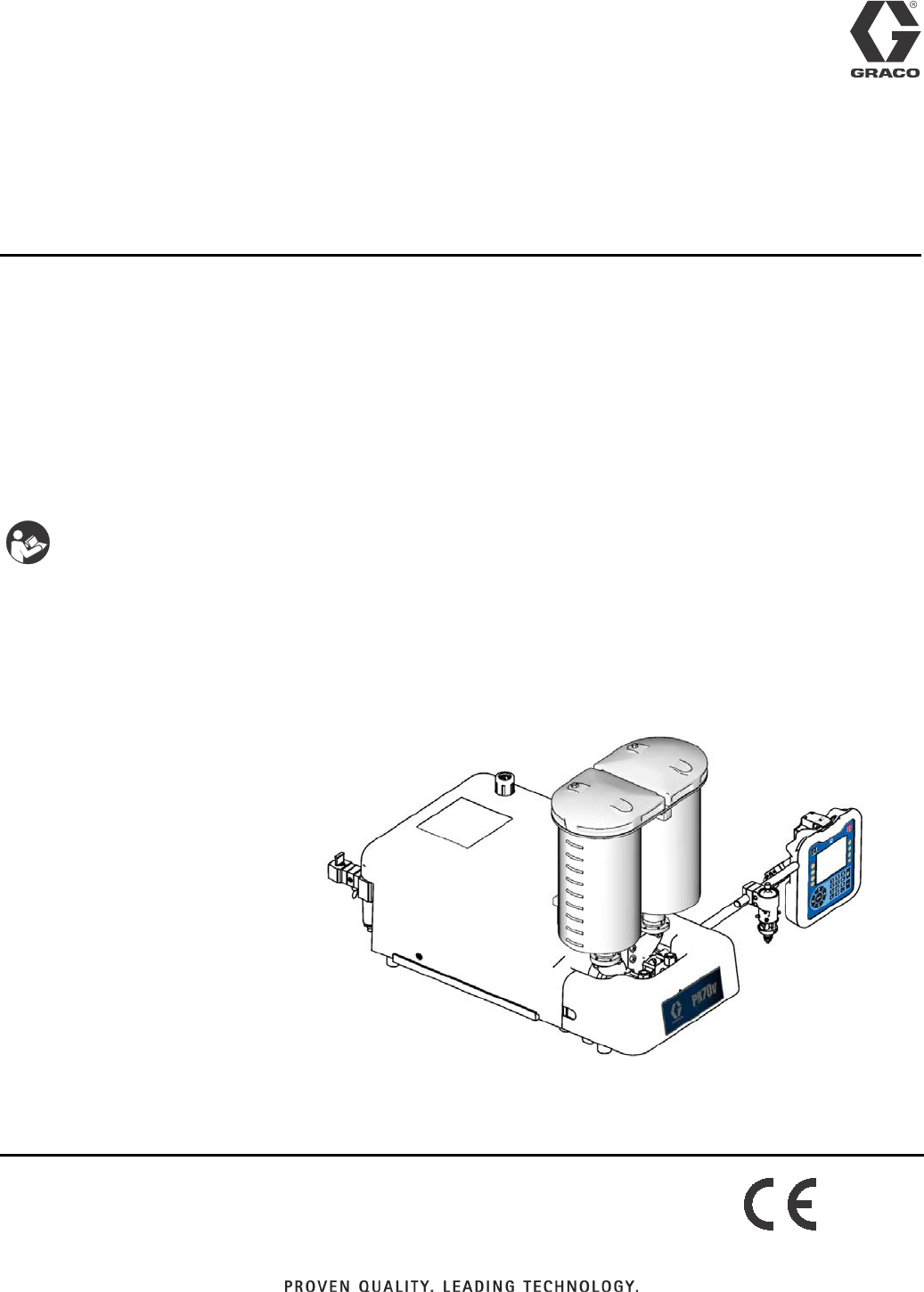
PR70™and PR70v™
Feed Systems
Fixed or variable ratio systems. For accurate metering, mixing, and dispensing of
two-component materials. For professional use only.
Not approved for use in European explosive atmosphere locations.
3000 psi (21 MPa, 207 bar) Maximum Working Pressure
100 psi (0.7 MPa, 7 bar) Maximum Air Inlet Pressure
Important Safety Instructions
Read all warnings and instructions in all sup-
plied manuals. Save these instructions.
ti12580b
PR70v shown with Polyethylene Tanks and
Advanced Display Module
312394V
EN

Related Manuals
2 312394V
Contents
Related Manuals ...........................2
Product Configurator .......................3
Warnings ................................10
Grounding ...............................12
Installation ...............................13
Polyethylene Tank Lid with Agitator .........13
Pneumatic Agitator Motor .................14
Level Sensors ..........................14
Auto-Refill Installation ....................16
Pressure Transducer and Flow Meter Installation 16
Startup ..................................17
Pressure Relief Procedure .................. 18
Models with Advanced Display Module .......18
Models with Standard Display Module .......18
Setup ....................................19
Level Sensor Calibration ..................19
Vacuum De-gas ........................20
Vacuum De-gas and Vacuum Auto-Fill .......21
Accumulator Filling ......................22
Shutdown ................................23
Repair ...................................24
Tank Removal ..........................24
Ball Valve Removal from Tank .............24
Ball Valve Repair .......................25
Agitator Fuse Replacement ..............26
Parts ....................................27
Accumulators, Assemblies LC0160 and LC0297 27
8 Liter Polyethylene Tanks ................30
Polyethylene Tank Agitators ...............32
On-Board Stainless Steel Tanks ............37
Ball Valve, Assembly 255280 ..............40
Flange Assembly, 256896 ................41
On-Board Stainless Steel Tank Lids .........42
Tanks for Use with Dust Covers ............44
Tanks for Use with Clampdown Covers ......44
Off-Board Stainless Steel Tanks ............46
Off-Board Stainless Steel Tank Lids .........49
Vacuum Tree Manifold, 255342 ............58
Vacuum Tree Manifold, 257746 ............58
Stainless Steel Tank Agitators .............60
Level Sensors ..........................66
Kits .....................................68
Dimensions ...............................70
Machine with On-Board Tanks .............70
Machine with Off-Board Tanks .............71
Technical Data ............................73
Graco Standard Warranty ...................74
Graco Information .........................74
Related Manuals
PR70 and PR70v Operation and Parts Manuals
Part Description
3A0429 PR70 with Standard Display Module Oper-
ation and Maintenance Manual
312759 PR70 and PR70v with Advanced Display
Module Operation and Maintenance Man-
ual
312760 PR70 and PR70v Repair and Parts Manual
312394 PR70 and PR70v Feed Systems Manual
312761 PR70v Integrated Heat Instructions - Parts
Manual
MD2 Dispense Valve Manual
Part Description
312185 MD2 Dispense Valve Instructions and Parts
Manual
Product Configurator
312394V 3
Product Configurator
An example of the product configurator would be the following configurator code.
The following part number fields apply for the PR70 and PR70v part numbering configurator fields. Shaded items
listed in the configurator table below are “Super Standard” items that are typically stocked and provide the best deliv-
ery dates.
PR7F - - - - - - - - - - - - - -----
Code: A B-C D-E F G-H I-J K L M N O P Q R S T U V
Air Motor
High Volume Side Piston
Low Volume Side Piston
Controls
High Volume Side Hose
Low Volume Side Hose
Dispense Valve
Mixer
Applicator Mounting
Power Cord
Flow Monitoring
High Volume Side Tank
High Volume Side Tank Cover
Low Volume Side Tank
Low Volume Side Tank Cover
Tank Level Sensors
Heat Zone Controller
Off-Board Tank Stand
PR7F - J - A5 - A5 - E - A6 - A6 - 3 - 1 - 2 - A - N - 3 - N - H - N - 6 - N - N
Code: A B-C D-E F G-H I-J K L M N O P Q R S T U V
Air Motor
High Volume Side Piston
Low Volume Side Piston
Controls
High Volume Side Hose
Low Volume Side Hose
Dispense Valve
Mixer
Applicator Mounting
Power Cord
Flow Monitoring
High Volume Side Tank
High Volume Side Tank Cover
Low Volume Side Tank
Low Volume Side Tank Cover
Tank Level Sensors
Heat Zone Controller
Off-Board Tank Stand
Code A Part Air Motor
A LC0262 PR70 with 3.0 in. (4.56 mm) Air Motor
B LC0264 PR70 with 4.5 in. (10.26 mm) Air Motor
C LC0263 PR70 with 3.0 in. (4.56 mm) Air Motor
and Hydracheck
D LC0265 PR70 with 4.5 in. (10.26 mm) Air Motor
and Hydracheck
F LC0242 PR70v with 3.0 in. (4.56 mm) Air Motor
G LC0244 PR70v with 4.5 in. (10.26 mm) Air
Motor
H LC0243 PR70v with 3.0 in. (4.56 mm) Air Motor
and Hydracheck
J LC0245 PR70v with 4.5 in. (10.26 mm) Air
Motor and Hydracheck
Code B Part
High Volume Side Piston and
Metering Tube Material
A LC1___ Nylon Piston, Stainless Steel Metering
Tube (last three digits of part number
is the mm2piston size)
B LC2___ UHMWPE Piston, Stainless Steel
Metering Tube (last three digits of part
number is the mm2piston size)
C LC3___ UHMWPE Piston, Ceramic Metering
Tube (last three digits of part number
is the mm2piston size)
Code C Part High Volume Piston Size (mm2)
180, Available in Nylon Only
2 100, Available in Nylon Only
3 120, Available in Nylon Only

Product Configurator
4 312394V
4 140, Available in Nylon Only
5 160
6 180
7 200
8 220
9 240
A 260
B 280
C 300
F 320
G 360
H 400
J 440
L 480
M 520
R 560
S 600
T 640
U 720
W 800
X 880
Y 960
Z Custom High Volume side, consult fac-
tory (stainless steel only)
Code D Part
Low Volume Side Piston and
Metering Tube Material
A LC1___ Nylon Piston, Stainless Steel Metering
Tube (last three digits of part number
is the mm2piston size)
B LC2___ UHMWPE Piston, Stainless Steel
Metering Tube (last three digits of part
number is the mm2piston size)
C LC3___ UHMWPE Piston, Ceramic Metering
Tube (last three digits of part number
is the mm2piston size)
Code E Part Low Volume Side Piston Size (mm2)
180, Available in Nylon Only
2 100, Available in Nylon Only
3120, Available in Nylon Only
4 140, Available in Nylon Only
5 160
6 180
7 200
8 220
9 240
A 260
B 280
C 300
F 320
G 360
H 400
J 440
L 480
M 520
R 560
S 600
T 640
U 720
W 800
X 880
Y 960
Z Custom Low Volume side, consult fac-
tory (stainless steel only)
Code F Part Controls
B LC0272 Standard Display Module with 1 Fluid
Control Module
D LC0274 Advanced Display Module with 1 Fluid
Control Module
E LC0275 Advanced Display Module with 2 Fluid
Control Modules
Codes
G-H,
I-J Part
High Volume Hose /
Low Volume Hose
A1 LC0801 3/16 in. (4.8 mm) - 2.5 ft (0.6 m)
A2 LC0802 3/16 in. (4.8 mm) - 10 ft (3.0 m)
A3 LC0803 3/16 in. (4.8 mm) - 15 ft (4.6 m)
A4 LC0804 1/4 in. (6.5 mm) - 2.5 ft (0.6 m)
A5 LC0805 1/4 in. (6.5 mm) - 10 ft (3.0 m)
A6 LC0806 1/4 in. (6.5 mm) - 15 ft (4.6 m)
A7 LC0807 3/8 in. (9.5 mm) - 2.5 ft (0.6 m)
A8 LC0808 3/8 in. (9.5 mm) - 10 ft (3.0 m)
A9 LC0809 3/8 in. (9.5 mm) - 15 ft (4.6 m)
AA LC0810 1/2 in. (13 mm) - 2.5 ft (0.6 m)
AB LC0811 1/2 in. (13 mm) - 10 ft (3.0 m)
AC LC0812 1/2 in. (13 mm) - 15 ft (4.6 m)
AG LC0813 3/4 in. (19 mm) - 10 ft (3.0 m)
AH LC0814 3/4 in. (19 mm) - 15 ft (4.6 m)
B4 LC0881 Heated, 1/4 in. (6.5 mm) - 2.5 ft (0.6 m)
B5 LC0882 Heated, 1/4 in. (6.5 mm) - 10 ft (3.0 m)
B6 LC0883 Heated, 1/4 in. (6.5 mm) - 15 ft (4.6 m)
B7 LC0884 Heated, 3/8 in. (9.5 mm) - 2.5 ft (0.6 m)
B8 LC0885 Heated, 3/8 in. (9.5 mm) - 10 ft (3.0 m)
B9 LC0886 Heated, 3/8 in. (9.5 mm) - 15 ft (4.6 m)
BA LC0887 Heated, 1/2 in. (13 mm) - 2.5 ft (0.6 m)
BB LC0888 Heated, 1/2 in. (13 mm) - 10 ft (3.0 m)
BC LC0889 Heated, 1/2 in. (13 mm) - 15 ft (4.6 m)
BG LC0890 Heated, 3/4 in. (19 mm) - 10 ft (3.0 m)
BH LC0891 Heated, 3/4 in. (19 mm) - 15 ft (4.6 m)
C1 LC0161 Recirculating, On-Board Tanks,
3/16 in. (4.8 mm) - 2.5 ft (0.6 m)
C2 LC0162 Recirculating, On-Board Tanks,
3/16 in. (4.8 mm) - 10 ft (3.0 m)

Product Configurator
312394V 5
C3 LC0163 Recirculating, On-Board Tanks,
3/16 in. (4.8 mm) - 15 ft (4.6 m)
C4 LC0164 Recirculating, On-Board Tanks,
1/4 in. (6.5 mm) - 2.5 ft (0.6 m)
C5 LC0165 Recirculating, On-Board Tanks,
1/4 in. (6.5 mm) - 10 ft (3.0 m)
C6 LC0166 Recirculating, On-Board Tanks,
1/4 in. (6.5 mm) - 15 ft (4.6 m)
C7 LC0167 Recirculating, On-Board Tanks,
3/8 in. (9.5 mm) - 2.5 ft (0.6 m)
C8 LC0168 Recirculating, On-Board Tanks,
3/8 in. (9.5 mm) - 10 ft (3.0 m)
C9 LC0169 Recirculating, On-Board Tanks,
3/8 in. (9.5 mm) - 15 ft (4.6 m)
CA LC0170 Recirculating, On-Board Tanks,
1/2 in. (13 mm) - 2.5 ft (0.6 m)
CB LC0171 Recirculating, On-Board Tanks,
1/2 in. (13 mm) - 10 ft (3.0 m)
CC LC0172 Recirculating, On-Board Tanks,
1/2 in. (13 mm) - 15 ft (4.6 m)
CD LC0173 Recirculating, On-Board Tanks,
3/4 in. (19 mm) - 10 ft (3.0 m)
CE LC0174 Recirculating, On-Board Tanks,
3/4 in. (19 mm) - 15 ft (4.6 m)
D1 LC0175 Recirculating, Off-Board Tanks,
3/16 in. (4.8 mm) - 2.5 ft (0.6 m)
D2 LC0176 Recirculating, Off-Board Tanks,
3/16 in. (4.8 mm) - 10 ft (3.0 m)
D3 LC0177 Recirculating, Off-Board Tanks,
3/16 in. (4.8 mm) - 15 ft (4.6 m)
D4 LC0178 Recirculating, Off-Board Tanks,
1/4 in. (6.5 mm) - 2.5 ft (0.6 m)
D5 LC0179 Recirculating, Off-Board Tanks,
1/4 in. (6.5 mm) - 10 ft (3.0 m)
D6 LC0180 Recirculating, Off-Board Tanks,
1/4 in. (6.5 mm) - 15 ft (4.6 m)
D7 LC0181 Recirculating, Off-Board Tanks,
3/8 in. (9.5 mm) - 2.5 ft (0.6 m)
D8 LC0182 Recirculating, Off-Board Tanks,
3/8 in. (9.5 mm) - 10 ft (3.0 m)
D9 LC0183 Recirculating, Off-Board Tanks,
3/8 in. (9.5 mm) - 15 ft (4.6 m)
DA LC0184 Recirculating, Off-Board Tanks,
1/2 in. (13 mm) - 2.5 ft (0.6 m)
DB LC0185 Recirculating, Off-Board Tanks,
1/2 in. (13 mm) - 10 ft (3.0 m)
DC LC0186 Recirculating, Off-Board Tanks,
1/2 in. (13 mm) - 15 ft (4.6 m)
DD LC0187 Recirculating, Off-Board Tanks,
3/4 in. (19 mm) - 10 ft (3.0 m)
DE LC0188 Recirculating, Off-Board Tanks,
3/4 in. (19 mm) - 15 ft (4.6 m)
E1 LC0190 Recirculating, Heated, On-Board
Tanks, 1/4 in. (6.5 mm) - 2.5 ft (0.6 m)
E2 LC0191 Recirculating, Heated, On-Board
Tanks, 1/4 in. (6.5 mm) - 10 ft (3.0 m)
E3 LC0192 Recirculating, Heated, On-Board
Tanks, 1/4 in. (6.5 mm) - 15 ft (4.6 m)
E4 LC0193 Recirculating, Heated, On-Board
Tanks, 3/8 in. (9.5 mm) - 2.5 ft (0.6 m)
E5 LC0194 Recirculating, Heated, On-Board
Tanks, 3/8 in. (9.5 mm) - 10 ft (3.0 m)
E6 LC0195 Recirculating, Heated, On-Board
Tanks, 3/8 in. (9.5 mm) - 15 ft (4.6 m)
E7 LC0196 Recirculating, Heated, On-Board
Tanks, 1/2 in. (13 mm) - 2.5 ft (0.6 m)
E8 LC0197 Recirculating, Heated, On-Board
Tanks, 1/2 in. (13 mm) - 10 ft (3.0 m)
E9 LC0198 Recirculating, Heated, On-Board
Tanks, 1/2 in. (13 mm) - 15 ft (4.6 m)
EA LC0199 Recirculating, Heated, On-Board
Tanks, 3/4 in. (19 mm) - 10 ft (3.0 m)
EB LC0200 Recirculating, Heated, On-Board
Tanks, 3/4 in. (19 mm) - 15 ft (4.6 m)
F1 LC0201 Recirculating, Heated, Off-Board
Tanks, 1/4 in. (6.5 mm) - 2.5 ft (0.6 m)
F2 LC0202 Recirculating, Heated, Off-Board
Tanks, 1/4 in. (6.5 mm) - 10 ft (3.0 m)
F3 LC0203 Recirculating, Heated, Off-Board
Tanks, 1/4 in. (6.5 mm) - 15 ft (4.6 m)
F4 LC0204 Recirculating, Heated, Off-Board
Tanks, 3/8 in. (9.5 mm) - 2.5 ft (0.6 m)
F5 LC0205 Recirculating, Heated, Off-Board
Tanks, 3/8 in. (9.5 mm) - 10 ft (3.0 m)
F6 LC0206 Recirculating, Heated, Off-Board
Tanks, 3/8 in. (9.5 mm) - 15 ft (4.6 m)
F7 LC0207 Recirculating, Heated, Off-Board
Tanks, 1/2 in. (13 mm) - 2.5 ft (0.6 m)
F8 LC0208 Recirculating, Heated, Off-Board
Tanks, 1/2 in. (13 mm) - 10 ft (3.0 m)
F9 LC0209 Recirculating, Heated, Off-Board
Tanks, 1/2 in. (13 mm) - 15 ft (4.6 m)
FA LC0210 Recirculating, Heated, Off-Board
Tanks, 3/4 in. (19 mm) - 10 ft (3.0 m)
FB LC0211 Recirculating, Heated, Off-Board
Tanks, 3/4 in. (19 mm) - 15 ft (4.6 m)
GA LC0400 High Pressure, 3/8 in. (9.5 mm) - 2.5 ft
(0.6 m)
GB LC0401 High Pressure, 3/8 in. (9.5 mm) - 10 ft
(3.0 m)
GC LC0402 High Pressure, 3/8 in. (9.5 mm) - 15 ft
(4.6 m)
GD LC0403 High Pressure, 1/2 in. (13 mm) - 2.5 ft
(0.6 m)
GE LC0404 High Pressure, 1/2 in. (13 mm) - 10 ft
(3.0 m)
GF LC0405 High Pressure, 1/2 in. (13 mm) - 15 ft
(4.6 m)

Product Configurator
6 312394V
GH LC0406 High Pressure, 3/4 in. (19 mm) - 10 ft
(3.0 m)
GJ LC0407 High Pressure, 3/4 in. (19 mm) - 15 ft
(4.6 m)
GK LC0432 High Pressure, Recirculating,
On-Board Tanks,
3/8 in. (9.5 mm) - 2.5 ft (0.6 m)
GL LC0433 High Pressure, Recirculating,
On-Board Tanks,
3/8 in. (9.5 mm) - 10 ft (3.0 m)
GM LC0434 High Pressure, Recirculating,
On-Board Tanks,
3/8 in. (9.5 mm) - 15 ft (4.6 m)
GQ LC0435 High Pressure, Recirculating,
On-Board Tanks,
1/2 in. (13 mm) - 2.5 ft (0.6 m)
GR LC0436 High Pressure, Recirculating,
On-Board Tanks,
1/2 in. (13 mm) - 10 ft (3.0 m)
GS LC0437 High Pressure, Recirculating,
On-Board Tanks,
1/2 in. (13 mm) - 15 ft (4.6 m)
GT LC0438 High Pressure, Recirculating,
On-Board Tanks,
3/4 in. (19 mm) - 10 ft (3.0 m)
GU LC0439 High Pressure, Recirculating,
On-Board Tanks,
3/4 in. (19 mm) - 15 ft (4.6 m)
GW LC0440 High Pressure, Recirculating,
On-Board Tanks,
3/8 in. (9.5 mm) - 2.5 ft (0.6 m)
GX LC0441 High Pressure, Recirculating,
On-Board Tanks,
3/8 in. (9.5 mm) - 10 ft (3.0 m)
GY LC0442 High Pressure, Recirculating,
On-Board Tanks,
3/8 in. (9.5 mm) - 15 ft (4.6 m)
G1 LC0443 High Pressure, Recirculating,
On-Board Tanks,
1/2 in. (13 mm) - 2.5 ft (0.6 m)
G2 LC0444 High Pressure, Recirculating,
On-Board Tanks,
1/2 in. (13 mm) - 10 ft (3.0 m)
G3 LC0445 High Pressure, Recirculating,
On-Board Tanks,
1/2 in. (13 mm) - 15 ft (4.6 m)
G4 LC0446 High Pressure, Recirculating,
On-Board Tanks,
3/4 in. (19 mm) - 10 ft (3.0 m)
G5 LC0447 High Pressure, Recirculating,
On-Board Tanks,
3/4 in. (19 mm) - 15 ft (4.6 m)
HA LC0472 High Pressure, Heated, 3/8 in. (9.5
mm) - 2.5 ft (0.6 m)
HB LC0473 High Pressure, Heated, 3/8 in. (9.5
mm) - 10 ft (3.0 m)
HC LC0474 High Pressure, Heated, 3/8 in. (9.5
mm) - 15 ft (4.6 m)
HF LC0475 High Pressure, Heated, 1/2 in. (13
mm) - 2.5 ft (0.6 m)
HG LC0476 High Pressure, Heated, 1/2 in. (13
mm) - 10 ft (3.0 m)
HJ LC0477 High Pressure, Heated, 1/2 in. (13
mm) - 15 ft (4.6 m)
HL LC0478 High Pressure, Heated, 3/4 in. (19
mm) - 10 ft (3.0 m)
HM LC0479 High Pressure, Heated, 3/4 in. (19
mm) - 15 ft (4.6 m)
HQ LC0480 High Pressure, Heated, 3/8 in. (9.5
mm) - 2.5 ft (0.6 m)
HR LC0481 High Pressure, Heated, 3/8 in. (9.5
mm) - 10 ft (3.0 m)
HS LC0482 High Pressure, Heated, 3/8 in. (9.5
mm) - 15 ft (4.6 m)
HT LC0483 High Pressure, Heated, 1/2 in. (13
mm) - 2.5 ft (0.6 m)
HU LC0484 High Pressure, Heated, 1/2 in. (13
mm) - 10 ft (3.0 m)
HX LC0485 High Pressure, Heated, 1/2 in. (13
mm) - 15 ft (4.6 m)
HY LC0486 High Pressure, Heated, 3/4 in. (19
mm) - 10 ft (3.0 m)
H2 LC0487 High Pressure, Heated, 3/4 in. (19
mm) - 15 ft (4.6 m)
NN --- Not required
Code K Part Dispense Valve
N N/A None
2 255179 MD2, Valve Only with 1:1 Nose
3 255181 MD2, Valve Only with 10:1 Nose
4 LC0120 MD2, Handheld with 1:1 Nose
5 LC0122 MD2, Handheld with 10:1 Nose
6 LC0121 MD2, Lever with 1:1 Nose
7 LC0123 MD2, Lever with 10:1 Nose
Code L Part Mixer Type
N N/A None
1 LC0063 3/16 in. (4.8 mm) x 32
2 LC0057 1/4 in. (6.4 mm) x 24
3 LC0058 3/8 in. (9.5 mm) x 24
4 LC0059 3/8 in. (9.5 mm) x 36
5 LC0060 3/8 in. (9.5 mm) Combo
6 LC0062 1/4 in. (6.4 mm) x 24 Luer Lock
7 LC0061 3/16 in. (4.8 mm) x 32 Luer Lock
8 LC0295 1/2 in. (12.7 mm) x 24
9 LC0296 1/2 in. (12.7 mm) x 36

Product Configurator
312394V 7
Code M Part Applicator Mounting
N LC0294 None, Customer Mount Controls and
Applicator
1 LC0292 Mast Mount, Controls & MD2 Applica-
tor Machine Mounted
2 LC0293 Mast Mount, Controls Only
3 256439 Tank Stand Mount, Controls & MD2
Applicator Machine Mounted
4 256438 Tank Stand Mount, Controls Only
Code N Part Power Cord Option
1 121055 120VAC North American Cord Set
2 121054 10A, 250V US Cord Set
3 121056 10A, 250V Continental europe
4 121057 10A, 250V U.K./Ireland
5 121058 10A, 250V Israel
6 124864 10A, 250V Australia
7 124861 10A, 250V Italy
8 124863 10A, 250V Switzerland
9 124862 10A, 250V Denmark
A 121060 10A, 250V India
B N/A Heat Controller Option
Code O Part Flow Monitoring
N LC0041 None
1 257433 Pressure Transducer
2 LC0302 Two 0.5 gpm Flow Meters, No Pres-
sure Transducers
3 LC0305 Two 1.0 gpm Flow Meters, No Pres-
sure Transducers
4 LC0303 One 1.0 gpm Flow Meter, One
0.5 gpm Flow Meter, No Pressure
Transducers
5 LC0307 Two 2.0 gpm Flow Meters, No Pres-
sure Transducers
6 LC0306 One 2.0 gpm Flow Meter, One
1.0 gpm Flow Meter, No Pressure
Transducers
7 LC0304 One 2.0 gpm Flow Meter, One 0.5 gpm
Flow Meter, No Pressure Transducers
A LC0312 Two 0.5 gpm Flow Meters, With Pres-
sure Transducers
B LC0315 Two 1.0 gpm Flow Meters, With Pres-
sure Transducers
C LC0313 One 1.0 gpm Flow Meter, One
0.5 gpm Flow Meter, With Pressure
Transducers
D LC0317 Two 2.0 gpm Flow Meters, With Pres-
sure Transducers
E LC0316 One 2.0 gpm Flow Meter, One
1.0 gpm Flow Meter, With Pressure
Transducers
F LC0314 One 2.0 gpm Flow Meter, One 0.5 gpm
Flow Meter, With Pressure Transduc-
ers
Code P Part High Volume Side Tank
N N/A None
1 256896 No Tanks, 1 1/2 in. npt flange
2 255241 8 L, Twin Polyethylene Tanks and Lids
3 255250 8 L, Twin Polyethylene Tanks and Lids,
One 120V Agitator
4 255251 8 L, Twin Polyethylene Tanks and Lids,
Two 120V Agitators
5 255281 8 L, Twin Polyethylene Tanks and Lids,
with Shut-Off Valves
6 255282 8 L, Twin Polyethylene Tanks and Lids,
One 120V Agitator, with Shut-Off
Valves
7 255283 8 L, Twin Polyethylene Tanks and Lids,
Two 120V Agitators, with Shut-Off
Valves
8 LC02357.5 L, Stainless Steel, High Level Sen-
sors
9 LC02367.5 L, Stainless Steel, High Level Sen-
sors, with Shut-Off Valve
A LC00133 L, Stainless Steel
B LC00127.5 L, Stainless Steel
C 2552853 L, Stainless Steel, with Shut-Off
Valve
D LC0156 8 L, Twin Polyethylene Tanks and Lids,
One Pneumatic Agitator
E LC0157 8 L, Twin Polyethylene Tanks and Lids,
Two Pneumatic Agitator
F 2552847.5 L, Stainless Steel, with Shut-Off
Valve
G LC02547.5 L, Stainless Steel, 240V Heat
H LC02557.5 L, Stainless Steel, 240V Heat,
with Shut-Off Valve
J LC0054 30 L, Stainless Steel
K LC0158 8 L, Twin Polyethylene Tanks and Lids,
One Pneumatic Agitator, with Shut-Off
Valves
L LC0259 30 L, Stainless Steel, 240V Heat
M LC0055 60 L, Stainless Steel
P LC0159 8 L, Twin Polyethylene Tanks and Lids,
Two Pneumatic Agitators, with
Shut-Off Valves
R LC0260 60 L, Stainless Steel, 240V Heat
S LC0126 8 L, Twin Polyethylene Tanks and Lids,
One 240V Agitator
T LC0127 8 L, Twin Polyethylene Tanks and Lids,
Two 240V Agitators
U LC0128 8 L, Twin Polyethylene Tanks and Lids,
One 240V Agitator, with Shut-Off
Valves
V LC02387.5 L, Stainless Steel, High Level Sen-
sors, 240V Heat, with Shut-Off Valve

Product Configurator
8 312394V
W LC0129 8 L, Twin Polyethylene Tanks and Lids,
Two 240V Agitators, with Shut-Off
Valves
X LC0160 Accumulator, Fluoroelastomer
Y LC0297 Accumulator, EP
Z LC02377.5 L, Stainless Steel, High Level Sen-
sors, 240V Heat
--- When ordering tanks for spare or
replacement parts, refer to Parts,
page 27.
Code Q Part High Volume Side Tank Cover
N N/A None
1 LC0018 On-Board Dust Cover
2 LC0019 On-Board Clamp Down
3 LC0020 On-Board Vacuum De-gas
4 LC0021 On-Board Agitate 120VAC 50/60 Hz
5 LC0022 On-Board Agitate 240VAC 50/60 Hz
6 LC0023 On-Board Agitate 120 VAC 50/60 Hz
and De-gas
7 LC0024 On-Board Agitate 240 VAC 50/60 Hz
and De-gas
8 LC0025 On-Board 120VAC 50/60 Hz, De-gas
and Fill-Port
9 LC0026 On-Board 240 VAC 50/60 Hz, De-gas
and Fill-Port
A LC0142 Off-Board Clamp Down - 30L
B LC0101 Off-Board Clamp Down - 60L
C LC0043 Off-Board Vacuum De-gas - 30L
F LC0102 Off-Board Vacuum De-gas - 60L
G LC0047 Off-Board Electric Agitator - 30L
H LC0048 Off-Board Electric Agitator - 60L
K LC0147 Off-Board Vacuum De-gas, Pneu-
matic Agitator, Fill Port, Slinger - 60 L
M LC0051 Off-Board Vacuum De-gas, Electric
Agitator, Fill Port, Slinger - 30 L
R LC0052 Off-Board Vacuum De-gas, Electric
Agitator, Fill Port, Slinger - 60 L
S LC0130 On-Board, Pneumatic Agitate
T LC0131 On-Board, Pneumatic Agitate, De-gas
U LC0132 On-Board, Pneumatic Agitate, De-gas,
Fill Port
V LC0142 Off-Board Pneumatic Agitator - 30 L
W LC0143 Off-Board Pneumatic Agitator - 60 L
Z LC0146 Off-Board Vacuum De-gas, Pneu-
matic Agitator, Fill Port, Slinger - 30 L
Code R Part Low Volume Side Tank
N N/A None
1 256896 No Tanks, 1 1/2 in. npt flange
8 LC02357.5 L, Stainless Steel, High Level Sen-
sors
9 LC02367.5 L, Stainless Steel, High Level Sen-
sors,
with Shut-Off Valve
A LC00133 L, Stainless Steel
B LC00127.5 L, Stainless Steel
C 2552853 L, Stainless Steel, with Shut-Off
Valve
F 2552847.5 L, Stainless Steel, with Shut-Off
Valve
G LC02547.5 L, Stainless Steel, 240V Heat
H LC02557.5 L, Stainless Steel, 240V Heat,
with Shut-Off Valve
J LC0054 30 L, Stainless Steel
L LC0259 30 L, Stainless Steel, 240V Heat
M LC0055 60 L, Stainless Steel
R LC0260 60 L, Stainless Steel, 240V Heat
V LC02387.5 L, Stainless Steel, High Level Sen-
sors,
240V Heat, with Shut-Off Valve
X LC0160 Accumulator, Fluoroelastomer
Y LC0297 Accumulator, EP
Z LC02377.5 L, Stainless Steel, High Level Sen-
sors,
240V Heat
--- When ordering tanks for spare or
replacement parts, refer to Parts,
page 27.
Code S Part Low Volume Side Tank Covers
N N/A None
1 LC0018 On-Board Dust Cover
2 LC0019 On-Board Clamp Down
3 LC0020 On-Board Vacuum De-gas
4 LC0021 On-Board Agitate 120VAC 50/60 Hz
5 LC0022 On-Board Agitate 240VAC 50/60 Hz
6 LC0023 On-Board Agitate 120 VAC 50/60 Hz
and De-gas
7 LC0024 On-Board Agitate 240 VAC 50/60 Hz
and De-gas
8 LC0025 On-Board 120VAC 50/60 Hz, De-gas
and Fill-Port
9 LC0026 On-Board 240 VAC 50/60 Hz, De-gas
and Fill-Port
A LC0142 Off-Board Clamp Down - 30L
B LC0101 Off-Board Clamp Down - 60L
C LC0043 Off-Board Vacuum De-gas - 30L
F LC0102 Off-Board Vacuum De-gas - 60L
G LC0047 Off-Board Electric Agitator - 30L
H LC0048 Off-Board Electric Agitator - 60L
K LC0147 Off-Board Vacuum De-gas, Pneu-
matic Agitator, Fill Port, Slinger - 60 L
M LC0051 Off-Board Vacuum De-gas, Electric
Agitator, Fill Port, Slinger - 30 L
R LC0052 Off-Board Vacuum De-gas, Electric
Agitator, Fill Port, Slinger - 60 L
S LC0130 On-Board, Pneumatic Agitate
T LC0131 On-Board, Pneumatic Agitate, De-gas

Product Configurator
312394V 9
U LC0132 On-Board, Pneumatic Agitate, De-gas,
Fill Port
V LC0142 Off-Board Pneumatic Agitator - 30 L
W LC0143 Off-Board Pneumatic Agitator - 60 L
Z LC0146 Off-Board Vacuum De-gas, Pneu-
matic Agitator, Fill Port, Slinger - 30 L
Code T Part Tank Level Sensors
N N/A None
2 LC0278 Polyethylene Tanks - Low Level Sen-
sors Only
3 LC0279 Two 7.5 L Stainless Steel Tanks - Low
Level Sensors Only
4 LC0282 Two 30 L or 60 L Stainless Steel Tanks
- Low Level Sensors Only
5 LC0281 7.5 L Stainless Steel - Low Level Sen-
sors Only, and 30 L or 60 L Stainless
Steel - Low Level Sensors Only
6 LC0280 Accumulator Sensors, and 7.5 L Low
Level Sensors
7 LC0283 Accumulator Sensors, and 30 L or
60 L Low Level Sensors
9 LC0284 Two 7.5 L Stainless Steel Tanks - High
and Low Level Sensors with Refill
Logic
A LC0287 Two 30 L or 60 L Stainless Steel Tanks
- High and Low Level Sensors with
Refill Logic
B LC0286 7.5 L Stainless Steel - Low Level Sen-
sors, and
30 L or 60 L Stainless Steel - High and
Low Level Sensors with Refill Logic
C LC0289 7.5 L Stainless Steel - High and Low
Level Sensors with Refill Logic, and
30 L or 60 L Stainless Steel - High and
Low Level Sensors with Refill Logic
D LC0285 Accumulator Sensors, and 7.5 L High
and Low Level Sensors
E LC0288 Accumulator Sensors, and 30 L or
60 L High and Low Level Sensors
G N/A Two Sets of Accumulator Sensors
Code U Part Heat Zone Controller
N N/A None
C LC0250 1 Tank or 1 Hose
D LC0251 2 Tanks, 1 Tank and 1 Hose, or 2
Hoses
E LC0252 2 Tanks and 1 Hose, or 1 Tank and 2
Hoses
F LC0253 2 Tanks and 2 Hoses
Code V Part Off-Board Tank Stands
N N/A None
2 LC0103 PR70 Tank Stand
3 LC0247 PR70v Tank Stand
Warnings
10 312394V
Warnings
The following warnings are for the setup, use, grounding, maintenance, and repair of this equipment. The exclama-
tion point symbol alerts you to a general warning and the hazard symbol refers to procedure-specific risk. Refer back
to these warnings. Additional, product-specific warnings may be found throughout the body of this manual where
applicable.
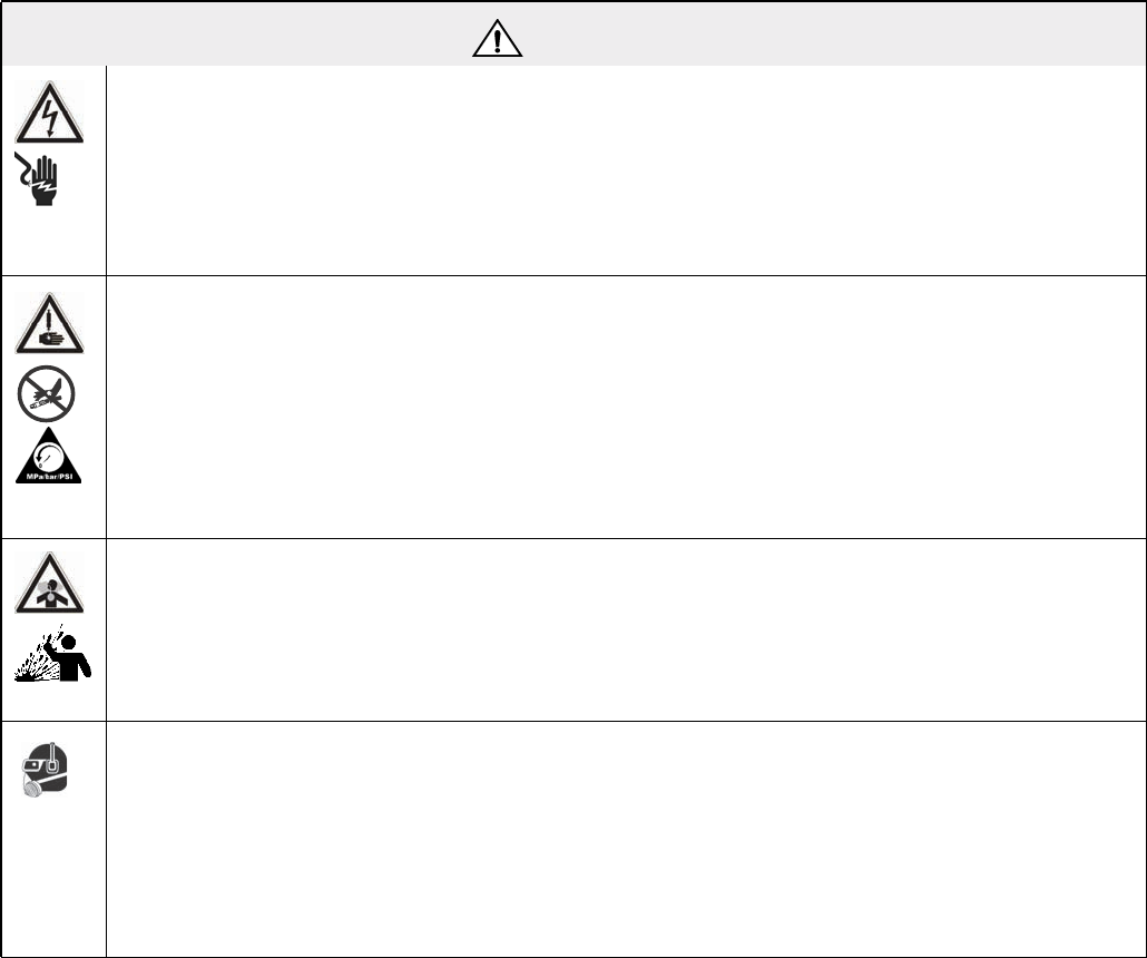
WARNING
ELECTRIC SHOCK HAZARD
Improper grounding, setup, or usage of the system can cause electric shock.
• Turn off and disconnect power cord before servicing equipment.
• Use only grounded electrical outlets.
• Use only 3-wire extension cords.
• Ensure ground prongs are intact on power and extension cords.
• Do not expose to rain. Store indoors.
SKIN INJECTION HAZARD
High-pressure fluid from dispense valve, hose leaks, or ruptured components will pierce skin. This may
look like just a cut, but it is a serious injury that can result in amputation. Get immediate surgical
treatment.
• Do not point dispense valve at anyone or at any part of the body.
• Do not put your hand over the end of the dispense nozzle.
• Do not stop or deflect leaks with your hand, body, glove, or rag.
• Follow Pressure Relief Procedure in this manual, when you stop spraying and before cleaning,
checking, or servicing equipment.
TOXIC FLUID OR FUMES HAZARD
Toxic fluids or fumes can cause serious injury or death if splashed in the eyes or on skin, inhaled, or
swallowed.
• Read MSDS’s to know the specific hazards of the fluids you are using.
• Store hazardous fluid in approved containers, and dispose of it according to applicable guidelines.
• Always wear impervious gloves when spraying or cleaning equipment.
PERSONAL PROTECTIVE EQUIPMENT
You must wear appropriate protective equipment when operating, servicing, or when in the operating
area of the equipment to help protect you from serious injury, including eye injury, inhalation of toxic
fumes, burns, and hearing loss. This equipment includes but is not limited to:
• Protective eyewear
• Clothing and respirator as recommended by the fluid and solvent manufacturer
• Gloves
• Hearing protection
Warnings
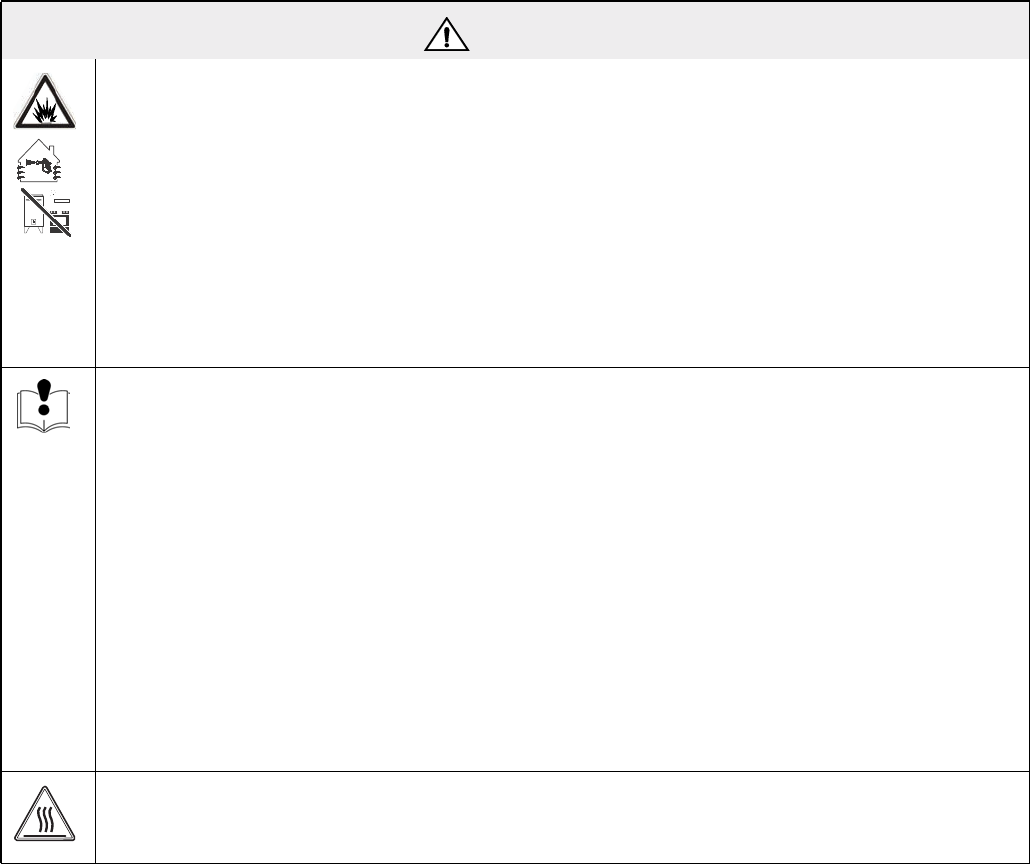
312394V 11
FIRE AND EXPLOSION HAZARD
Flammable fumes, such as solvent and paint fumes, in work area can ignite or explode. To help prevent
fire and explosion:
• Use equipment only in well ventilated area.
• Eliminate all ignition sources; such as pilot lights, cigarettes, portable electric lamps, and plastic
drop cloths (potential static arc).
• Keep work area free of debris, including solvent, rags and gasoline.
• Do not plug or unplug power cords or turn lights on or off when flammable fumes are present.
• Ground all equipment in the work area. See Grounding instructions.
• If there is static sparking or you feel a shock, stop operation immediately. Do not use equipment
until you identify and correct the problem.
• Keep a working fire extinguisher in the work area.
EQUIPMENT MISUSE HAZARD
Misuse can cause death or serious injury.
• Do not operate the unit when fatigued or under the influence of drugs or alcohol.
• Do not exceed the maximum working pressure or temperature rating of the lowest rated system
component. See Technical Data in all equipment manuals.
• Use fluids and solvents that are compatible with equipment wetted parts. See Technical Data in all
equipment manuals. Read fluid and solvent manufacturer’s warnings. For complete information
about your material, request MSDS forms from distributor or retailer.
• Check equipment daily. Repair or replace worn or damaged parts immediately with genuine manu-
facturer’s replacement parts only.
• Do not alter or modify equipment.
• Use equipment only for its intended purpose. Call your distributor for information.
• Route hoses and cables away from traffic areas, sharp edges, moving parts, and hot surfaces.
• Do not kink or over bend hoses or use hoses to pull equipment.
• Keep children and animals away from work area.
• Comply with all applicable safety regulations.
BURN HAZARD
Equipment surfaces and fluid that’s heated can become very hot during operation. To avoid severe
burns, do not touch hot fluid or equipment. Wait until equipment/fluid has cooled completely.
WARNING

Grounding
12 312394V
Grounding
Products that include electric agitators, heated hoses, or
heated tanks must be grounded. In the event of an elec-
trical short circuit, grounding reduces the risk of electric
shock by providing an escape wire for the electric cur-
rent. This product is equipped with a cord having a
grounding wire with an appropriate grounding plug. The
plug must be plugged into an outlet that is properly
installed and grounded in accordance with all local
codes and ordinances.
Improper installation of the grounding plug is able to
result in a risk of electric shock. When repair or replace-
ment of the cord or plug is required, do not connect the
grounding wire to either flat blade terminal. The wire
with insulation having an outer surface that is green with
or without yellow stripes is the grounding wire. Do not
modify the plug provided; if it does not fit the outlet, have
the proper outlet installed by a qualified electrician. Only
connect the product to an outlet having the same config-
uration as the plug. Do not use an adapter with this
product.
Installation
312394V 13
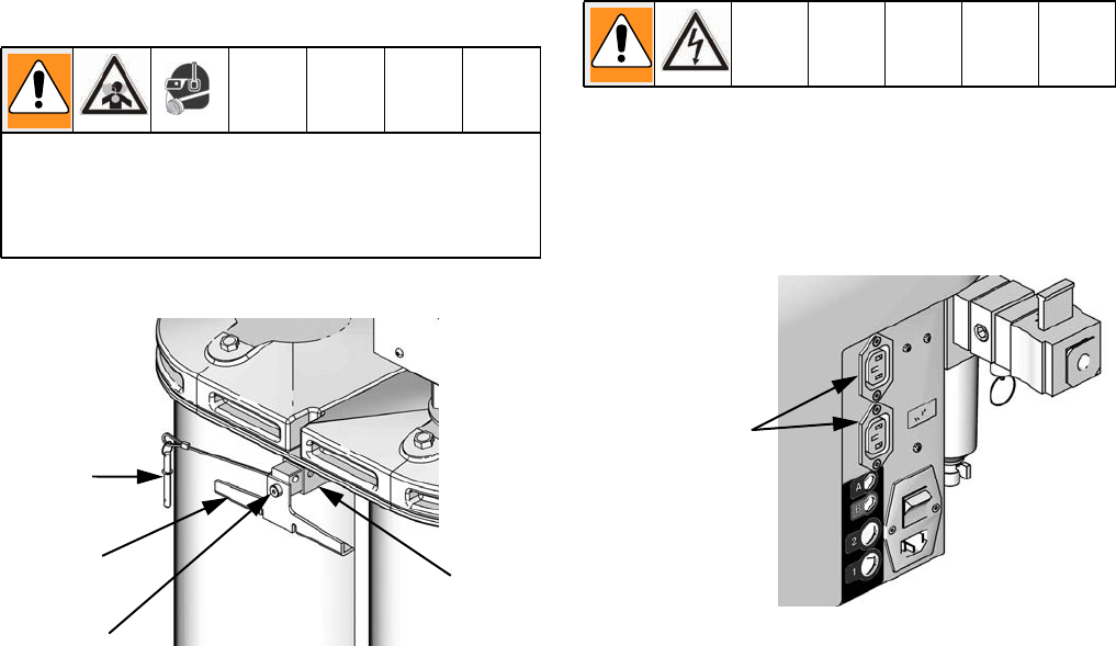
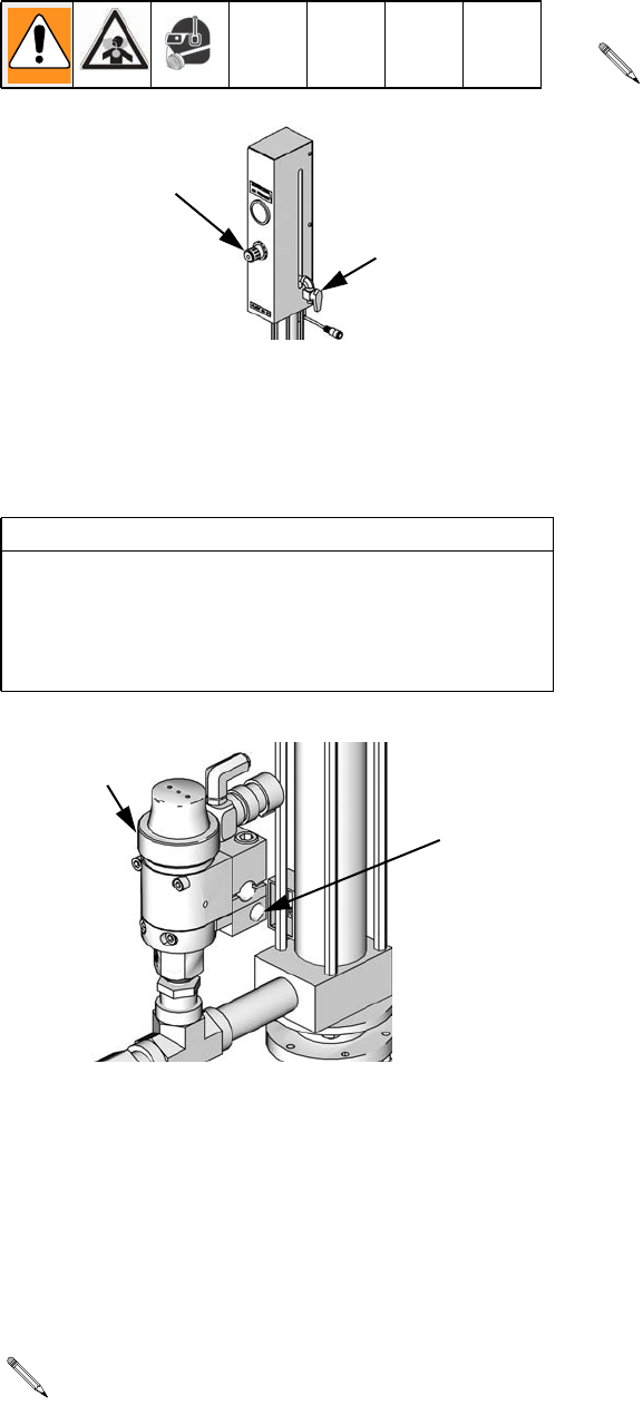
Installation
Polyethylene Tank Lid with
Agitator
1. Remove tethered quick-release pin (213) from both
sides of tank support beam (224).
2. Slide the clamp (222) out of each side of the sup-
port beam (224) until it hits the stop.
3. Rotate the clamp (222) 180 degrees about the
shoulder screw (214) so it is hanging freely.
4. The tank lid assembly can now be removed or
installed as required. Install tank lid assembly onto
tank body.
5. Rotate the clamp (222) 180 degrees about the
shoulder screw (214) so it is in position to secure
the tank lids.
6. With the clamps in position, slide the tethered
quick-release pin (213) into place.
7. Attach appropriate hoses and cables.
• For electric agitator models, plug the agitator
power cable into one of the outlets in the incom-
ing power bracket then turn on the power switch
located on the agitator.
The polyethylene tank lid o-ring is installed with Kry-
tox. Contact with Krytox can lead to flu-like symp-
toms. The MSDS for this material is available upon
request.
222
213
224
214 ti12558a
Power Outlets
to Electric Agi-
tator
ti12583a
Installation
14 312394V
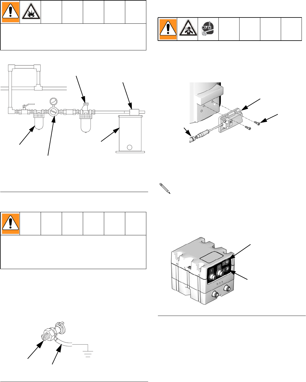
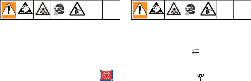
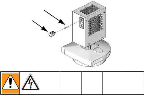
Pneumatic Agitator Motor
Ground Pneumatic Agitator Motor
To ground the agitator connect one end of the ground
wire (A) to the ground connector (B) on the agitator
mounting bracket. Connect the other end of the wire to a
true earth ground. For a replacement ground wire and
clamp, order Part 237569.
Level Sensors
Polyethylene Tanks
1. Install sensor (2001) using two screws (2003). The
cable (2002) for the sensor should be pointing
towards the center of the machine base.
2. Plug the sensor cable (2002) into the connector on
the Fluid Control Module as shown in FIG.3.
3. Calibrate the sensors. See Level Sensor Calibra-
tion, page 19.
Always maintain a minimum of one inch clearance
between rotating agitator parts and container to pre-
vent sparks caused by contact.
FIG. 1: Typical Installation
The equipment must be grounded. Grounding
reduces the risk of static and electric shock by pro-
viding an escape wire for the electrical current due to
static build up or in the event of a short circuit.
FIG. 2: Ground Agitator Motor
Air Line Lubricator
Agitator Motor
Air Line Filter
* Air Regulator and Gauge
Mix Tank
(reference only)
* Do not use an air regulator and gauge with pneumatic
air motor 01/0368-1/11.
B
A
Each machine will have either one or two Fluid
Control Modules, each labeled as #1 or #2. Fluid
Control Module #1 is always used for the low level
sensors. Fluid Control Module #2 is always used for
the high level sensors. See FIG.3.
FIG. 3: Fluid Control Module
2003
2001
2002
ti12493b
High Volume Side
Low Volume Side
ti12337a
Installation
312394V 15
Stainless Steel Tanks
1. Empty the tank.
2. Insert the PTFE proximity sensor well (2102) into
the tank and turn until flush with the flat face of the
tank.
3. Insert the proximity sensor (2101) into the proximity
sensor well (2102).
4. Hand tighten the well cap (2103) into the proximity
sensor well.
5. Plug the sensor connector (2104) into the connector
on the Fluid Control Module as shown in FIG.3.
6. Calibrate the sensor. See Level Sensor Calibra-
tion, page 19.
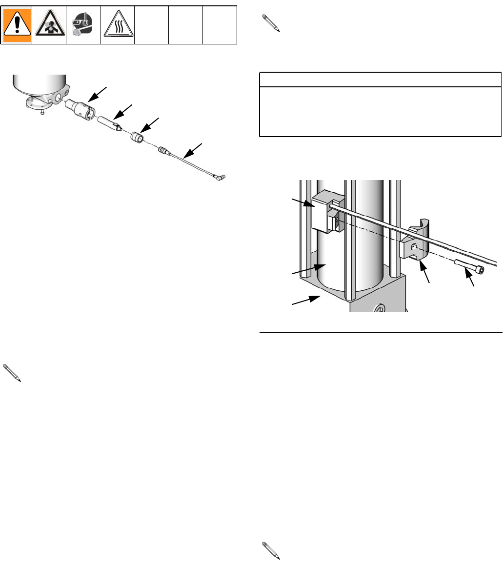
Accumulators
1. Place the main sensor body (144a) against the side
of the main cylinder (123) wall.
2. Line up the bolt holes of the clamp (144b) and the
main sensor body (144a). Lightly clamp the two
together around the nearest tie rod by finger tighten-
ing the socket head cap screw (144c) provided.
3. For accumulator low level sensors, once the
screw (144c) is finger-tight, slide the sensor (144)
so it is located 1/2 in. (13 mm) above the bottom
pump flange (111).
For accumulator high level sensors, once the
screw (144c) is finger-tight, slide the sensor (144)
so it is located 1-1/2 in. (38 mm) below the top pump
flange (111).
4. Plug the sensor connector into the connector on the
Fluid Control Module as shown in FIG.3.
Each machine will have either one or two Fluid
Control Modules, each labeled as #1 or #2. Fluid
Control Module #1 is always used for the low level
sensors. Fluid Control Module #2 is always used for
the high level sensors. See FIG.3.
2102
2101
2103
2104
ti12494a
The accumulator level sensors (144) can be
installed on any side of the main cylinder (123).
However, the sensor must be the specified distance
from the pump flange.
CAUTION
To prevent machine damage, if the material being
cycled through the accumulator is moisture sensitive,
a dryer must be installed in the air supply line before
the accumulator.
FIG.4
Each machine will have either one or two Fluid
Control Modules, each labeled as #1 or #2. Fluid
Control Module #1 is always used for the low level
sensors. Fluid Control Module #2 is always used for
the high level sensors. See FIG.3.
ti12592a
144a
144b 144c
111
123
Installation
16 312394V
Auto-Refill Installation
The Auto-Refill assembly is shipped uninstalled. The
Auto-Refill assembly can be installed in multiple places
on the tanks. See FIG.5.
Pressure Transducer and Flow
Meter Installation
See manual 312760.
FIG. 5: Auto-Refill Installation Locations
ti12393a
1
Possible locations for Auto-Refill installation.
1
1
Startup
312394V 17
Startup
1. Locate power switch at rear of machine and turn
power on. The display module will automatically turn
on and begin to load.
2. Slide the system air pressure relief switch up. It is
the yellow tab located at the rear, left of the
machine. The hole in the tab should not be showing.
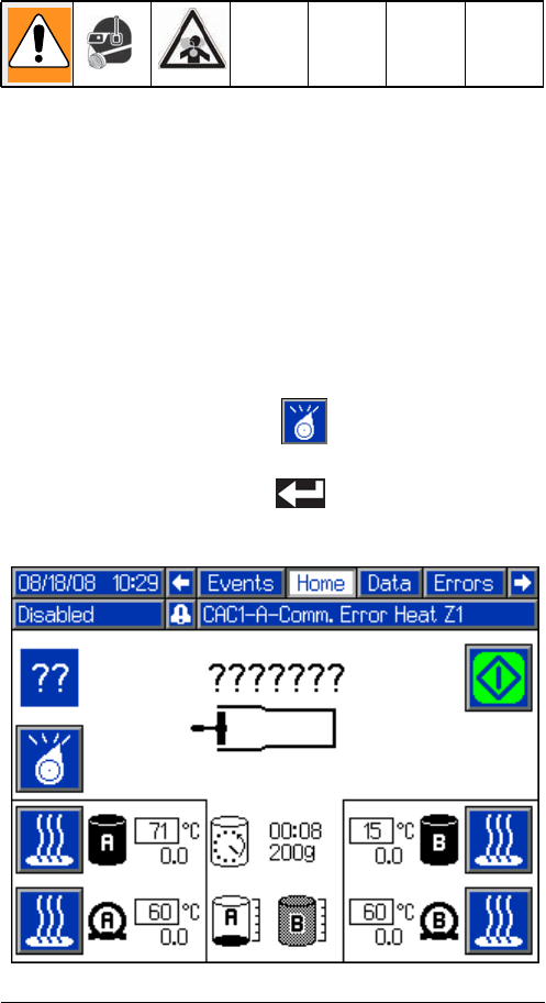
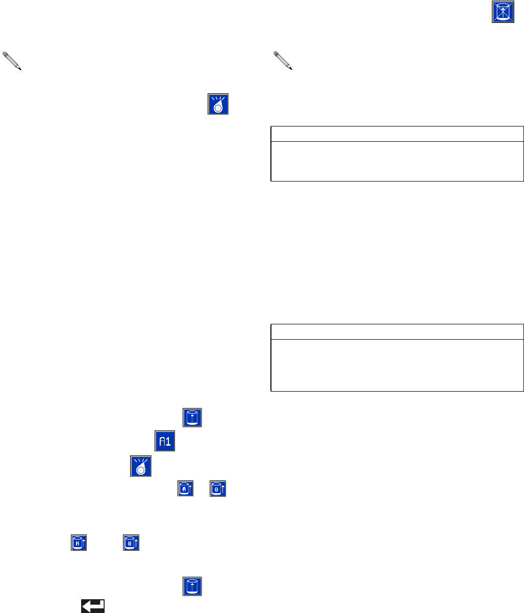
3. For systems with an Advanced Display Module:
if the machine is in Disabled Mode, press the Select
Operating Mode button ( ) repeatedly to exit
Disabled mode and to select a new operating mode.
Press the Enter button ( ) to accept the new
operating mode.
FIG. 6: Advanced Display Module - Disabled Mode
Pressure Relief Procedure
18 312394V
Pressure Relief Procedure
Models with Advanced Display
Module
1. Place a waste container below the dispense valve.
2. Navigate to the Manual screen.
3. Press the Open Dispense Valve button on the Man-
ual screen to relieve chemical pressure.
4. Press the Machine Disable Mode button ( ).
5. Press the system air pressure relief switch down to
stop air supply and to vent air pressure in the
machine. It is the yellow tab at the left, rear of the
machine. The hole in the tab should be visible.
6. If necessary, run a lock through the hole to lock the
tab in place. This prevents the system air pressure
from being inadvertently enabled.
Models with Standard Display
Module
With the machine in an idle state:
1. If the machine pistons are not fully retracted, retract
the pistons by pressing in the M1 screen. See
manual 3A0429 for more information.
2. Manually open the dispense valve by pressing the
third M1 soft key until the “ ” ICON is shown in the
Current DV field. See manual 3A0429 for more infor-
mation.
3. Press the system air pressure relief switch down to
stop air supply and to vent air pressure in the
machine. It is the yellow tab at the left, rear of the
machine. The hole in the tab should be visible.
4. If necessary, run a lock through the hole to lock the
tab in place. This prevents the system air pressure
from being inadvertently enabled.
Setup
312394V 19
Setup
Level Sensor Calibration
Polyethylene Tanks
1. Empty tanks by executing multiple shots.
2. Relieve pressure. See Pressure Relief Procedure,
page 18.
3. With the level sensor installed, locate the “[OUT
OFF]” button. Activate teach mode by holding the
button down for at least two seconds but no more
than six seconds.
4. The LED will flash once and then go out. This sig-
nals that the sensor is now in standard operating
mode.
5. Using appropriate protective wear, check the sensor
for proper operation by reaching inside the tank and
placing hand in the area of the sensor. If the LED
lights up with your hand next to the sensor, it is func-
tioning properly.
Stainless Steel Tanks
1. Locate the calibration button on the sensor (2101)
closest to the electrical connector through one of
the four holes of the sensor well (2102).
2. If the calibration button cannot be seen through one
of the four holes in the sensor well, rotate the sen-
sor.
a. Loosen the sensor well cap (2103).
b. Rotate sensor until the calibration button can be
seen through one of the four holes in the sensor
well.
c. Tighten sensor well cap (2103).
d. Press and hold the button down with the ball
end of an allen wrench for two seconds. The
light will flash slowly and then go out.
3. Test for proper sensor function.
a. Loosen the sensor well cap (2103).
b. Back the sensor out of the well. The sensor
should sense the tank wall.
Accumulators
The accumulator low level sensors cannot be calibrated.
To ensure proper accumulator sensor operation ensure
the sensor is located in the correct location as described
in the Level Sensors installation section, page 14.
2003
2001
2002
Teach
Element ti12493b
2102
2101
2103
2104
ti12494a
Setup
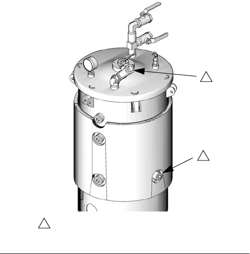
20 312394V
Vacuum De-gas
1. Models with ADM: To prevent machine movement,
press the Machine Disable Mode key ( ).
Models with SDM: To prevent machine movement,
press the Red button .
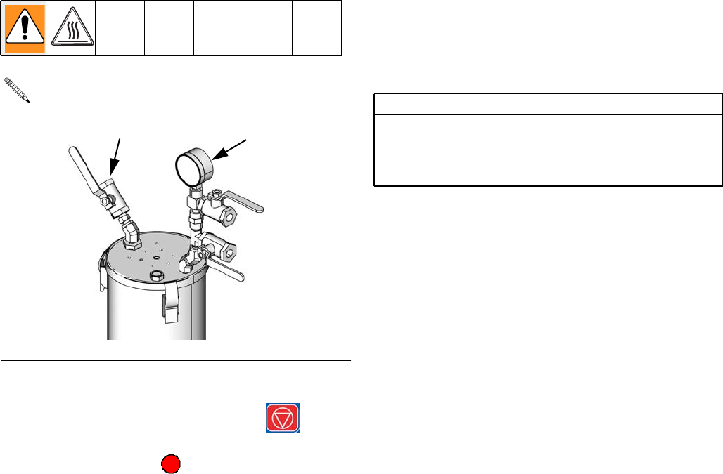
2. Close the shut-off ball valves at the base of the
tanks.
3. If the tank lid has a fill port, turn off any systems that
might refill the tank during the vacuum de-gas pro-
cedure.
4. Close the fill port ball valve (1034).
5. If the tank lid requires a desiccant dryer or nitrogen
pump installed, install one into the top ball valve of
the vacuum tree manifold (1015).
6. Close the top ball valve of the vacuum tree
manifold (1015).
7. Attach vacuum pump to the bottom ball valve of the
vacuum tree manifold (1015) then open the ball
valve.
8. Turn on the vacuum pump.
9. Continue to de-gas for sufficient time to de-gas the
material.
10. Close bottom ball valve of the vacuum tree
manifold (1015).
11. Turn off the vacuum pump.
12. Open the top ball valve of the vacuum tree
manifold (1015).
13. Open the shutoff valves at the base of the tanks.
This procedure is for assemblies with Vacuum Tree
Manifold and No Agitator or Auto-Refill. See FIG.7.
FIG.7
1034 1015
ti12560a
CAUTION
Operating the tank after the vacuum de-gas proce-
dure without the top ball valve open will result in pump
cavitation, off-ratio conditions, and possible collapse
of the tank.
Setup
312394V 21
Vacuum De-gas and Vacuum
Auto-Fill
1. Press the Select Operating Mode button ( )
repeatedly to select Shot, Sequence, or Operator
(Manual) mode.
2. Close the shut-off ball valves at the base of the
tanks.
3. If the tank lid requires a desiccant dryer or nitrogen
pump installed, install one into the top ball valve of
the vacuum tree manifold (1015).
4. Close the top ball valve of the vacuum tree
manifold (1015).
5. Attach vacuum pump to the bottom ball valve of the
vacuum tree manifold (1015) then open the ball
valve.
6. Turn on the vacuum pump.
7. Turn on agitator.
8. Select Manual Auto-Refill mode. See operation
manual referenced at the beginning of this manual
for more information.
9. Press the Initiate Auto-Refill button ( ). The
Active Shot/Sequence button ( ) and Select
Operating Mode button ( ) will each change to
the Auto-Refill Tank Select button ( or ) if a
valid Auto-Refill mode is enabled for both tanks.
10. Press the appropriate Auto-Refill Tank Select button
or buttons ( and/or ) to select the tanks to
refill.
11. Press the Initiate Auto-Refill button ( ) or the
Enter button ( ) to confirm.
12. If necessary, press the Abort/Cancel button ( )
to cancel auto-refill.
13. Continue to de-gas for sufficient time to de-gas the
material.
14. Close bottom ball valve of the vacuum tree
manifold (1015).
15. Turn off the vacuum pump.
16. Open the top ball valve of the vacuum tree
manifold (1015).
17. Open the shutoff valves at the base of the tanks.
This procedure is for assemblies with a Vacuum
Tree Manifold, Agitator, and Auto-Refill. See FIG.7
on page 20 for part references.
If an auto-refill is aborted or times out, the software
will not initiate a new auto-refill until a manually initi-
ated auto-refill has completed. To complete a man-
ually initiated auto-refill after an aborted or timed
out auto-refill, restart at step 2.
CAUTION
If an auto-refill is stopped and not restarted as
described in the previous note, the pumps may be run
dry and chemical crossover at the valve may occur.
CAUTION
Operating the tank after the vacuum de-gas proce-
dure without the top ball valve open will result in pump
cavitation, off-ratio conditions, and possible collapse
of the tank.
Setup
22 312394V
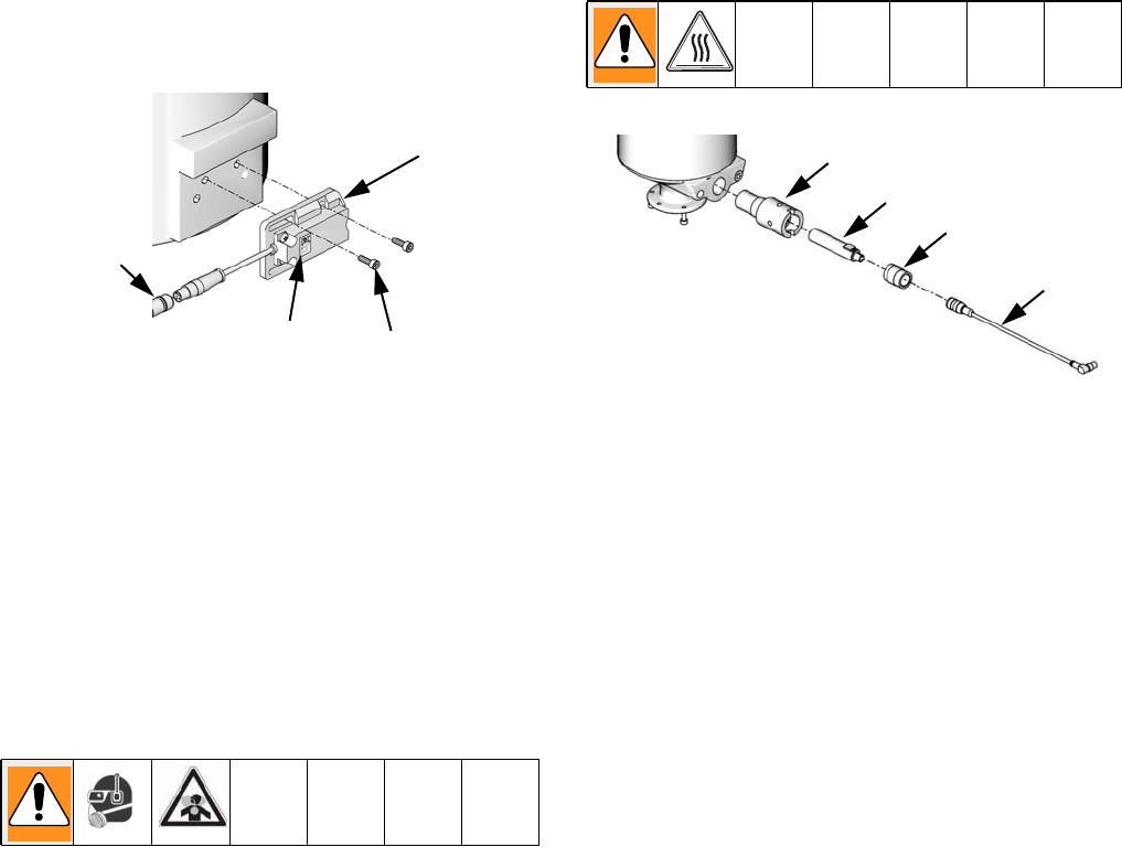
Accumulator Filling
1. Relieve accumulator air pressure to zero using
accumulator air pressure regulator (106).
2. Install material feed line to accumulator material
inlet (143a) on refill valve (143).
3. Place a waste container below the ball valve (109).
4. Open the ball valve (109).
5. Slowly increase air pressure until the accumulator
begins filling slowly.
6. Close the ball valve (109) when material begins to
spill into the waste container.
7. Use accumulator air pressure regulator (106) to
adjust to desired accumulator air pressure.
8. See the PR70 and PR70v Operation manual refer-
enced at the beginning of this manual to adjust dis-
play module run settings for the accumulator.
CAUTION
The refill valve has an open port on one side and a
closed port on the other. Do not remove the plug
opposite the material inlet (143a). The valve will not
function properly if the plugged side of the valve is
changed.
The vent tube is now full. The accumulator will fin-
ish filling and it will stop when the fluid level
reaches the high level sensor.
109
106
ti12561a
ti12629a
143a
143
Accumulator air pressure should be set to the low-
est possible setting to adequately run the accumu-
lator.

Shutdown
312394V 23
Shutdown
If the machine is to remain idle for an extended period of
time, perform the following steps.
1. Place a waste container below the dispense valve.
2. If installed, remove static mixer from the end of the
dispense valve.
3. Place a container below the dispense valve and
activate a small shot to flush mixed material out of
the valve.
4. Relieve pressure. See Pressure Relief Procedure
on page 18.
5. With a clean rag and cotton swabs, clean the end of
the dispense valve.
6. Install nightcap on the dispense valve.
Repair
24 312394V
Repair
Tank Removal
1. On models without ball valves, empty tanks by
executing multiple shots.
On models with ball valves, close the ball valves.
2. Relieve pressure. See Pressure Relief Procedure,
page 18.
3. For polyethylene tank models, remove the two
screws (211) that attach the tank T-beam support to
the pump sub-assembly.
4. On models without ball valves, loosen but do not
remove the six socket head cap screws (204) that
hold the tank to the pump housing.
On models with ball valves, remove the six socket
head cap screws (204) that hold the ball valve to the
pump housing. The tanks can now be pulled off of
the pump housing.
5. On models without ball valves, remove the tanks.
•For polyethylene tank models, rotate the lock
ring (218) for each tank counter clockwise and
lift the tanks off of the base.
•For stainless steel tank models, rotate the
tank counter clockwise and lift the tank off of the
base.
Ball Valve Removal from Tank
Polyethylene Tanks
1. Remove polyethylene tank assembly from the base.
2. Remove the six M5 screws (215) holding the two
ball valves to the polyethylene tank assembly.
211
ti12566a
204
218
ti12567a
CAUTION
Disassembly of the ball valve is not recommended.
Ensure the ball valve does not accidentally disassem-
ble when detaching the ball valve from the tank.
215
ti12566a
Repair
312394V 25
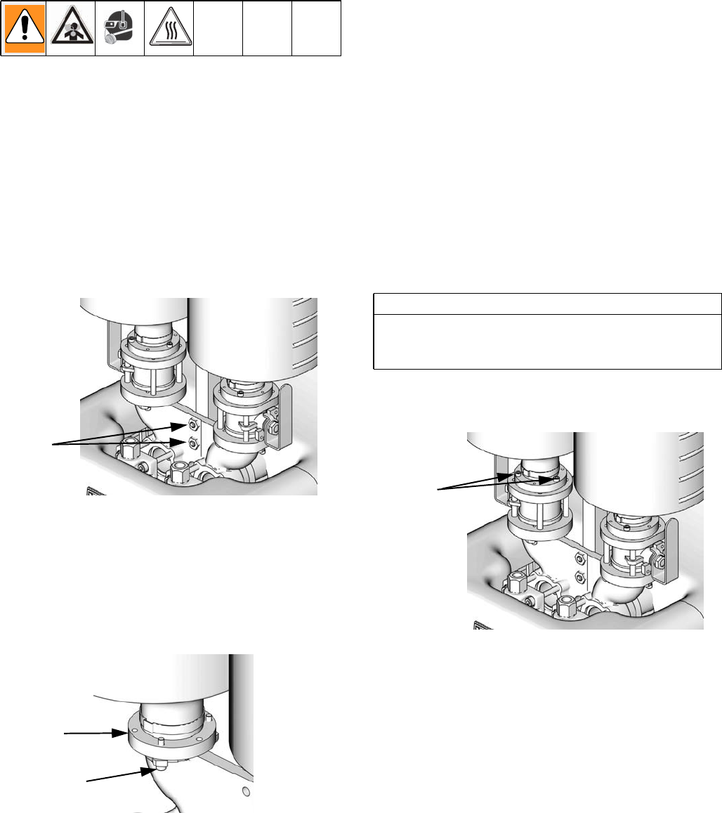
Stainless Steel Tanks
1. Remove the stainless steel tanks from the base.
2. Remove four long screws (506d) holding the ball
valve assembly together.
3. Remove three screws (505) holding the tank to the
top plate of the ball valve assembly.
Ball Valve Repair
1. Remove ball valve from tank.
2. Check o-rings and replace as necessary.
3. Reassemble and install the four screws that hold the
ball valve assembly together. Follow ball valve
removal from tank procedure in reverse order.
CAUTION
Disassembly of the ball valve is not recommended.
When the ball valve is removed from the tank, it is
disassembled.
503
506a
505
506b
506c
506d
503
504
Assembly 255284 Shown ti12453a
2202
2201
2205
2206
2203
2204
2204
ti12564a
Repair
26 312394V
Agitator Fuse Replacement
1. Slide open the fuse drawer (706).
2. Remove old fuse (707) and replace with new fuse.
706
707
ti12559a
Parts
312394V 27
Parts
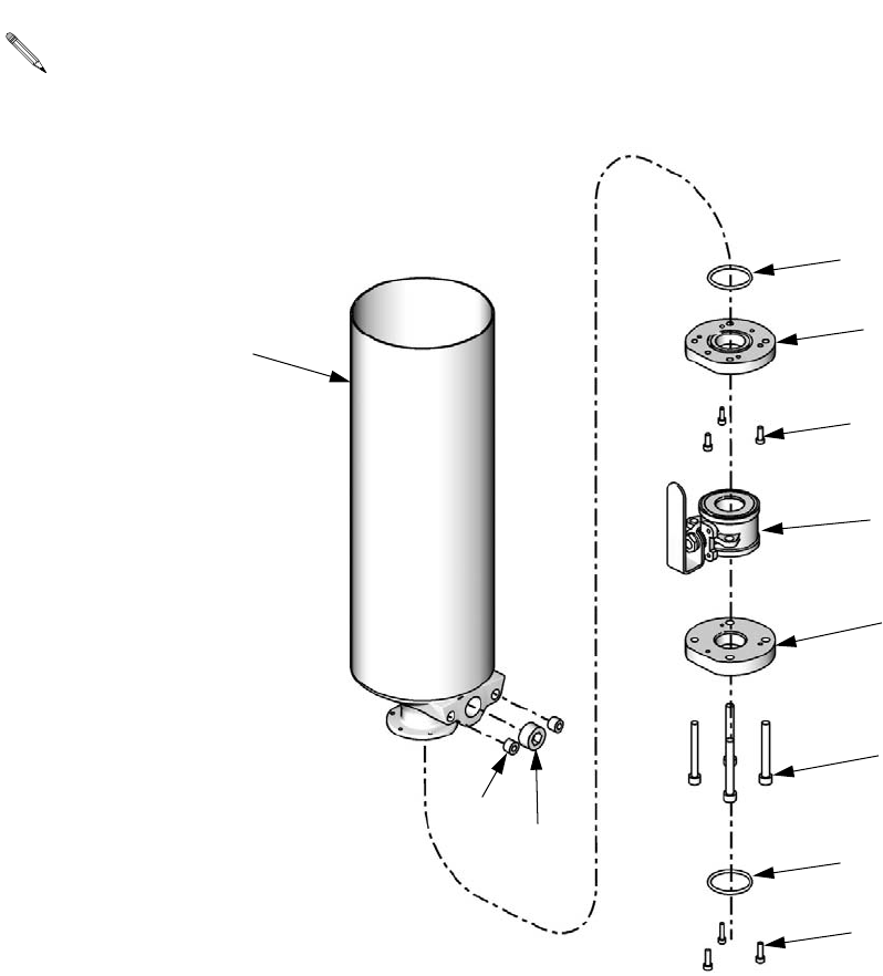
Accumulators, Assemblies
LC0160 and LC0297
126
127
128
124
144
144
122
123
129
136
130
131
132
133
127 111, 121
112
143
142
113
141
114
115
119
116
118
116
117
Apply thread sealant tape to male npt
threads prior to installation.
1
ti12449a
Parts
28 312394V
Accumulators, continued
105
108
125
120 140
139
137
138
102
103
135
135
106
135
103
108
109
107 134
101
Apply thread sealant tape to male npt threads prior to installation.
1
ti12472a
Parts
312394V 29
✖Not shown.
Ref Part Description Qty
101 15T679 COVER, front, accumulator,
mild steel, PR70
1
102 01/1449/99 COVER, back, accumulator,
mild steel
1
103 96/0282/98 FASTENER, screw, button
head cap screw, 8-32 x
0.38, stainless steel
6
104 84/1460-1/11 LABEL, accumulator, air
pressure
1
105 82/0053/11 GAUGE, 0-30psi, 2 in., 1/8
npt, back
1
106 82/0052/11 REGULATOR, air, 1/8 npt,
3-30 psig, 10 scfm
1
107 94/0070/96 FITTING, nipple, 1/8 npt x
1.50, brass
1
108 94/0642/96 FITTING, elbow, 1/8 npt,
female, 90deg, brass
2
109 94/0809/96 VALVE, ball, 2w, 1/8 npt,
male, lp, brass
1
110 15T686 LABEL, accumulator, plant
air in
1
111 01/1454/98 FLANGE, pump, accumula-
tor, 1.5, stainless steel
1
112 121307 FITTING, nipple, 1/2 npt x
3.00, male / male, 304
1
113 94/0616/98A FITTING, tee, 1/2 npt,
female, 3000 psi, 316 ss
1
114 94/0360-2/98 VALVE, check, 1/2 npt,
male, fluoroelastomer, stain-
less steel, adj
1
115 94/0348/11 CAP, valve, check, 1/2 1
116 95/0223/02 O-RING
(assembly LC0297 only)
2
95/0223/00 O-RING, fluoroelastomer
(assembly LC0160 only)
2
117 120904 SCREW, socket head cap,
M5x0.8x18mm
3
118 15M849 ADAPTER, accumulator 1
119 96/0304-4/98 NUT, hex, lock, 10-24, stain-
less steel
8
120 94/3201/96 FITTING, union, bulkhead,
1/4 tube
1
121 94/0545/98 PLUG, socket head, 1/8npt,
18-8 stainless steel
1
122 01/1453/99 ROD, tie, accumulator, 1.5 4
123 01/1455/98 CYLINDER, accumulator,
1.5, stainless steel
1
124 01/1451/98 TUBE, vent, accumulator,
1.5, stainless steel
1
125 94/0702/96 FITTING, 1/4tube x 1/8 npt,
male, brass
1
126 01/1456/97 CAP, end, cylinder, accumu-
lator, 1.5
1
127 95/0913/02 O-RING, ep, jbh
(assembly LC0297 only)
2
95/0913/00 O-RING, fluoroelastomer,
jbh (assembly LC0160 only)
2
128 95/0605/01 SEAL, u-cup, 1/2 ID x 3/4
OD, NIT
1
129 96/0611-08/98 NUT, jam, 1/2-20, stainless
steel
1
130 96/0556-08/99 WASHER, Sealing, 1/2, mild
steel
1
131 95/0601/02 SEAL, u-cup, 1-3/16 ID x
1-1/2OD, EP
(assembly LC0297 only)
1
95/0601/00 SEAL, u-cup, 1-3/16 ID x
1-1/2 OD, fluoroelastomer
(assembly LC0160 only)
1
132 16M909 MAGNET, accumulator, 1.5 1
133 16M880 PISTON, accumulator, 1.5 1
134 94/0527/96 FITTING, elbow, str, 1/8 npt,
90 deg, brass
1
135 94/0705-1/96 FITTING, elbow, swivel, 1/4
tube x 1/8 npt
3
136 96/0514/98 WASHER, flat, 1/2, 0.53 x
1.06 x 0.097, stainless steel
1
137 94/0463/96 FITTING, bushing, 1/8 npt x
10-32, brass
1
138 82/0171/11 FITTING, elbow, street,
10-32, adjustable, brass
1
139 82/0241/11 VALVE, qck exh, 10-32, mini 1
140 94/0102/96 CONNECTOR,
1/4tubex10-32, brass
1
141 94/0301-1/98 FITTING, elbow, strt, 90,
1/2 npt, stainless steel
1
142 94/0568/98 BUSHING, 1/2x1/4npt,
male/female, stainless steel,
6K, 316
1
143 256179 VALVE, assy, on-board tank
refill
1
144 LC0310 HARNESS, reed sw, QC,
assy
2
145 121684 CABLE, M12 x M8, 4P,
female/male,
straight/right angle, 2 m
2
146 121686 CABLE, M8 x M8, 4P,
female/male, straight/right
angle, 2 m
1
147✖94/1063/11 FITTING, tee, union, 1/4
tube
1
148✖84/0130-27/11 LABEL, hand crush 1
149✖23526-01 WASHER, nylon 1
Ref Part Description Qty
Parts
30 312394V
8 Liter Polyethylene Tanks
CAUTION
The electric agitators used with on-board tanks will fail
prematurely when material viscosity exceeds
24,000 cps. Use pneumatic agitators if material vis-
cosity exceeds 24,000 cps.
216
209
220
203
207
223
210
202
215
218
219
201
217
201
204
214222
221
205
211
224
208
206
213
212
Apply thread sealant tape to male npt threads prior to installation.
Do not attempt to remove from tank. Disassembling will damage tank.
1
2
Assembly 255282 Shown
2
2
2
2
ti12450a

Parts
312394V 31
* Parts included in kit 255481.
† Parts included in kit 255479.
Parts included in kit 255480.
** Part not shown.
Ref Part Description
Quantity
255241, Tank
255281, Tank with Ball Valves
255282, Tank with Ball Valves
and One 120V Agitator
255283, Tank with Ball Valves
and Two 120V Agitators
255250, Tank with
One 120V Agitator
255251, Tank with
Two 120V Agitators
LC0126, Tank with
One 240V Agitator
LC0127, Tank with
Two 240V Agitators
LC0128, Tank with Ball Valves
and One 240V Agitator
LC0129, Tank with Ball Valves
and Two 240V Agitators
LC0156, Tank with
One Pneumatic Agitator
LC0157, Tank with
Two Pneumatic Agitators
LC0158, Tank with Ball Valves
and One Pneumatic Agitator
LC0159, Tank with Ball Valves
and Two Pneumatic Agitators
201 †*
95/0223/00
O-RING, fluoroelastomer, bbc 24442222442244
202 †*O-RING 44444444442222
203 120902 SCREW, button head cap screw, M5
x0.8x40mm 22222222222222
204 †*
120904
SCREW, socket head cap,
M5x0.8x18mm 66666666666666
205 120905 NUT, HEX, lock M5 X 0.8 22222222222222
206 120906 NUT, HEX, lock M8 X 1.25 22222222222222
207 120907 WASHER, plain #10 42222222222222
208 120908 WASHER, plain M8 44444444444444
209 †*
120909
BREATHER 22222222222222
210 †*CLAMP, gap-free pinch hose 22222222222222
211 120913 SCREW 22222222222222
212 120925 RETAINER, lanyard with tab 222222222222
213 120927 FASTENER, quick-release pin 222222222222
214 120929 SCREW, shoulder, M5 x 0.8 x 6 mm 222222222222
215 121013 SCREW, M5 x 0.8 x 25 mm,
socket head cap, stainless steel 666 66 66
216 255246 AGITATOR, 120V, assembly 1212
255503 AGITATOR, 240V, assembly 1212
255730 AGITATOR, pneumatic, assembly 1212
217 255280 VALVE, ball 222 22 22
218 †*RING, lock 22222222222222
219 †*FITTING, flange 22222222222222
220 †*
15K840
O-RING 22222222222222
221 15K882 RETAINER, slide, clamp,
8L PE tank 222222222222
222 15K883 CLAMP, dual 8L PE tank 222222222222
223 †TANK, assembly 11
TANK, assembly 111111
*TANK, assembly 111111
224 15M226 BALLAST 111 11 11
15K842 BALLAST 1 1111 11
225 **120915 CAP, plug, square 22
Parts
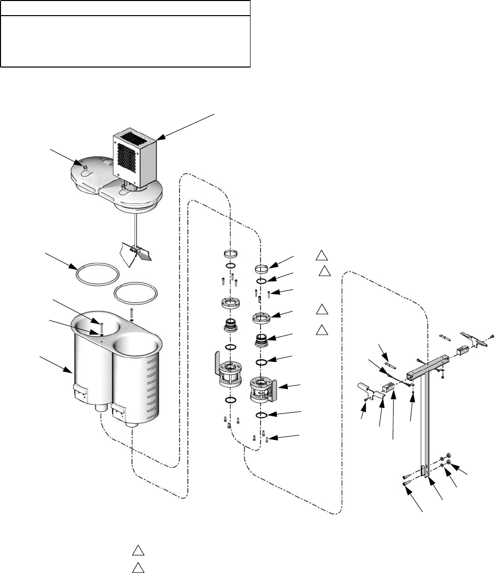
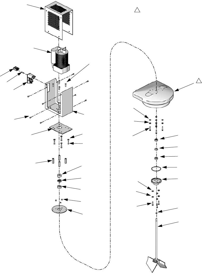
32 312394V
Polyethylene Tank Agitators
Electric Agitator Assemblies 255246 and 255503
717
715
716 720
710
720
711
723
717
715
716
721
725
701
704
706
707
705
712
703 715
719
702
724 708
709
708
714
Assembly 255246 Shown
Shown for reference only.
1
1
718
713
ti12456a
Parts
312394V 33
† Part not shown.
Ref Part Description Qty
701 01/2218/97 ENCLOSURE, agitator, electric, prmv/f, hd 1
703 01/2219/97 PLATE, adapter, electric agitator, hd, prm 1
704 81/2218-1/11 MOTOR, 50 rpm, 60 in-lb, 120V, 1.2A
(assembly 255246 only)
1
256613 MOTOR, 50 rpm, 60 in-lb, 230V
(assembly 255503 only)
1
705 81/1040/11 MODULE, ac, 2p, 250V, 10a, double pull sin-
gle throw, w/fuse
1
706 81/1040-1/11 MODULE, ac connector, 2P, 250V, 10A, with
bar
1
707 81/1053-1.6/11 FUSE,5x20mm,1.6A, time delay 1
708 84/2215-A/11 COUPLING, alignment, 1 in. OD, hub, 3/8 ID 2
709 84/2215-B/11 COUPLING, alignment, 1 in. OD, disk, nylon 1
710 95/0842/11 SEAL, posipak, 3/8ID x 7/8OD, P/fluoroelas-
tomer
1
711 95/0864/00 O-RING, fluoroelastomer, ada 1
712 96/0271/99 FASTENER, button head cap screw, 8-32 x
0.31, mild steel
8
713 96/0817/99 RING, retaining, external, 0.375, mild steel 1
714 120905 NUT, hex, lock M5 x 0.8 3
715 120907 WASHER, plain #10 11
716 120928 SCREW, button head cap screw, M5 x 0.8 x
25 mm
7
717 120930 WASHER, seal, fluoroelastomer 7
718 120960 SCREW, button head cap screw, M5 x 0.8 x
20 mm, stainless steel
4
719 120961 SCREW, button head cap screw, 10-32 x
1.25 in., stainless steel
4
720 121173 BEARING, ball,
3/8 in. ID x 7/8 in. OD x 9/32 in.
2
721 255724 AGITATOR, shaft and blade assy 1
723 15K884 HOUSING, bearing 1
724 15K885 SPACER, agitator standoff 4
725 15K886 DISK, bearing 1
726 †121599 CORD, power, v-lock, C14/C13, 10A 1
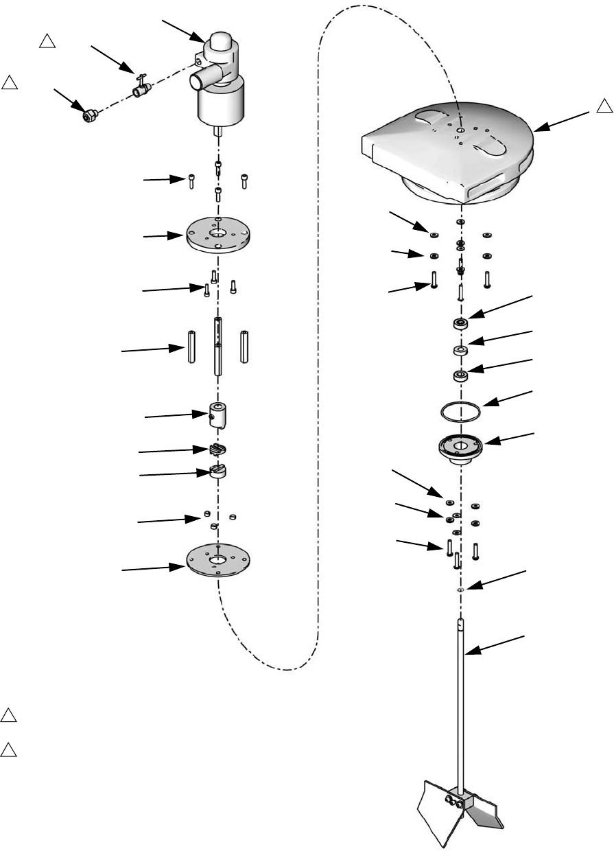
Parts
34 312394V
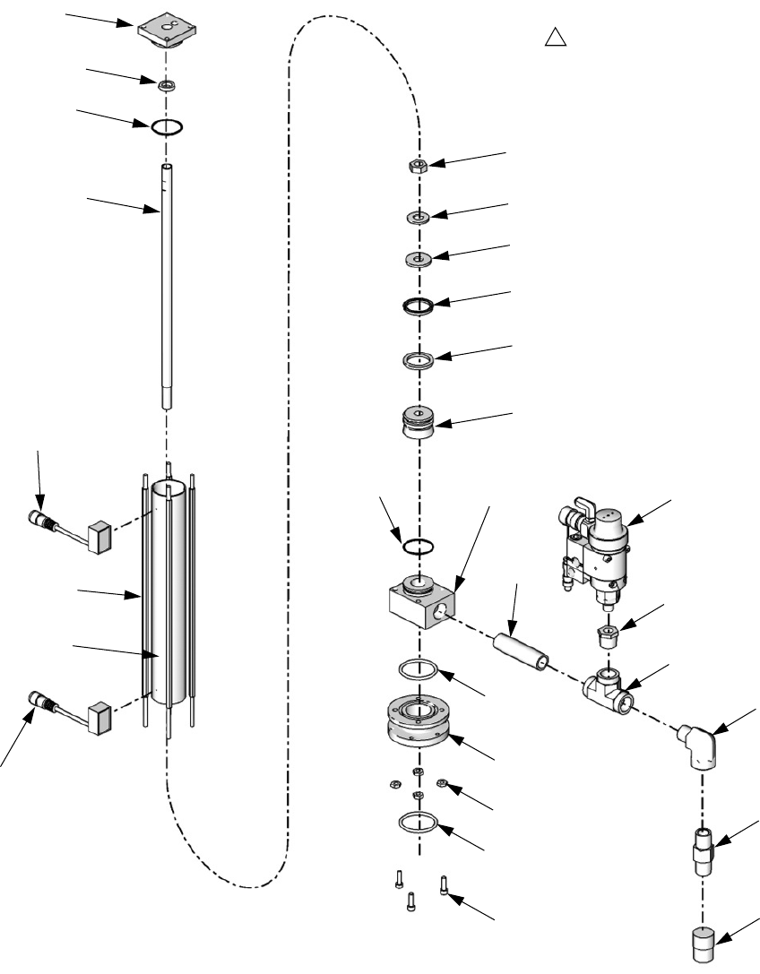
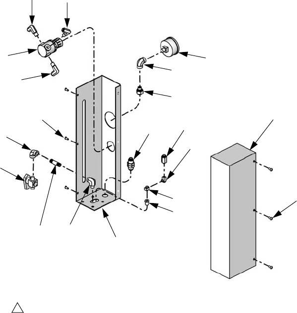
Pneumatic Agitator Assembly 255730
818
817
815
816
809
818
810
821
817
815
816
819
801
802
808
813
823
805
824
804, 811
807
806
814
822
Apply thread sealant tape to male npt
threads prior to installation.
Shown for reference only.
1
2
1
1
2
812
ti12457a
Parts
312394V 35
Ref Part Description
801 82/0216/11 MOTOR, motor, pneumatic, agitator, 0.32 hp 1
802 94/0838/96 VALVE, needle, 1/8 npt x 1/8 npt, male /
female
1
804 01/1189/98 ADAPTER, coupling, air motor, agitator 1
805 5-01-0510 SCREW, socket head cap, 10-32 x 5/8 in. 3
806 84/2215-A/11 COUPLING, alignment, 1 in. OD, hub,
3/8 in. ID
1
807 84/2215-B/11 COUPLING, alignment, 1 in. OD, disk, nylon 1
808 94/0702/96 FITTING, 1/4 tube x 1/8 npt, male, brass 1
809 95/0842/11 SEAL, posipak, 3/8ID x 7/8OD, P/fluoroelas-
tomer
1
810 95/0864/00 O-RING, fluoroelastomer, ADA 1
811 96/0029/99 SCREW, socket head, 5/16-24 x 0.25, cup
point
1
812 96/0817/99 RING, retaining, external, 0.375, mild steel 1
813 120904 SCREW, socket head cap, M5 x 0.8 x 18 mm 4
814 120905 NUT, hex, lock M5 x 0.8 3
815 120907 WASHER, plain #10 7
816 120928 SCREW, button head cap screw, M5 x 0.8 x
25 mm
7
817 120930 WASHER, seal, fluoroelastomer 7
818 121173 BEARING, ball, 3/8 in. ID x 7/8 in. OD
x 9/32 in.
2
819 255724 AGITATOR, shaft and blade assy 1
821 15K884 HOUSING, Bearing 1
822 15K886 DISK, bearing 1
823 15R363 ADAPTER, plate, pneumatic agitator 1
824 15R364 SPACER, standoff, pneumatic agitator 4
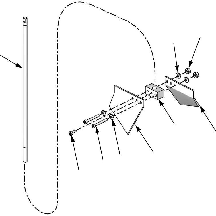
Parts
36 312394V
Agitator Shaft, 255724
907
904
903
905 901
902
901
906
905
ti12458a
Ref Part Description Qty
901 01/2230-1/98 PADDLE, agitator, tfm tank, stainless steel 2
902 01/2230-2/98 SUPPORT, mount, paddle, agitator 1
903 96/0097/98 FASTENER, screw, socket head cap, 10-24
x 1.25, stainless steel
2
904 96/0125/98 FASTENER, screw, socket head cap,
10-24 x 0.50, stainless steel
1
905 96/0129/98 WASHER, flat, SAE, #10, stainless steel,
1/2 in. OD, 0.049
4
906 96/0304-4/98 NUT, hex, lock, 10-24, stainless steel 2
907 15R307 SHAFT, agitator, 8L polyethylene tanks 1
Parts
312394V 37
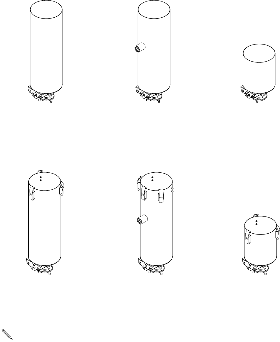
On-Board Stainless Steel Tanks
Tank Assemblies LC0237, LC0238,
LC0254, and LC0255
Right hand tank shown, left hand tank is mirror image.
306
309
301
308
307
305
303
302
304
2
Use glass cloth tape to secure ground strap, thermal switch, and RTD to tank wall before adding heat blanket.
Secure heat blanket to tank with string laced through eyelets.
Insulation blanket should cover heat blanket completely. Secure insulation blanket to tank with 2 in. wide velcro
strap.
The RTD sensor assembly (308) should always be connected to side one of the M8 splitter harness (306). Side
one is on the female/female end of connector and is marked with a molded imprint of the number “1”. The RTD
sensor assembly (305) should always be connected to side two of the M8 splitter harness (306).
1
2
3
4
11
3
Assembly LC0237 Shown
304a
4
4ti12451a
4

Parts
38 312394V
† Not shown. See Integrated Heat manual referenced at beginning of this manual.
▲Replacement Danger and Warning labels, tags, and cards are available at no cost.
Ref Part Description Qty
301 --- Refer to Tanks for Use with Dust Covers and
Tanks for Use with Clampdown Covers, page
44, for replacement or spare parts.
1
302 LC0861 BLANKET, heat, 7.5L tank, 220V 1
303 256558 SWITCH, assy, thermal, 125C, 3P, M8 1
304 LC0056 BLANKET, insulation 1
304a 121208 LABEL, hot surface
305 256611 SENSOR, assy, 1.5 in. rtd, 4-pin M8 1
306 121615 HARNESS, splitter, M8, 4-pin, female/male, 3 m 1
307 121478 FITTING, compression, 3/16 x 1/4 npt 1
308 256612 SENSOR, assy, 4.25 in. rtd, 4-pin M8 1
309 121682 CABLE, M8, 3-pin, male / female, 3 meter,
molded
1
310 †121633 CIRCUIT, breaker, 2-pole, 4A, C type 1
Parts
312394V 39
Tank Assemblies 255284, 255285, LC0235, LC0236, LC0012, and LC0013
† See Ball Valve, Assembly 255280, page 40 for
parts information.
It is recommended that the flat face of the tank
faces the back of the base machine. Right hand
tank shown, left hand tank is mirror image.
503
506a
505
506c
503
504
507
501
502
Assembly 255284 Shown
506b
506d
ti12453a
Ref Part Description Qty
501 94/0370/98 PLUG, socket head, 1/4 npt,
stainless steel
2
502 94/0372/98 PLUG, socket head, 3/4 npt,
stainless steel
1
503 95/0223/00 O-RING, fluoroelastomer, bbc 2
504 120904 SCREW, socket head cap, M5 x
0.8 x 18mm
3
505 121011 SCREW, M5 x 0.8 x 14mm,
socket head cap, stainless steel
(assemblies 255284, 255285,
LC0235, and LC0236 only)
3
506 †255280 VALVE, ball, shutoff (assemblies
255284, 255285, LC0235, and
LC0236 only)
1
507 --- Refer to Tanks for Use with
Dust Covers and Tanks for Use
with Clampdown Covers, page
44, for replacement or spare
parts.
1
Ref Part Description Qty
Parts
40 312394V
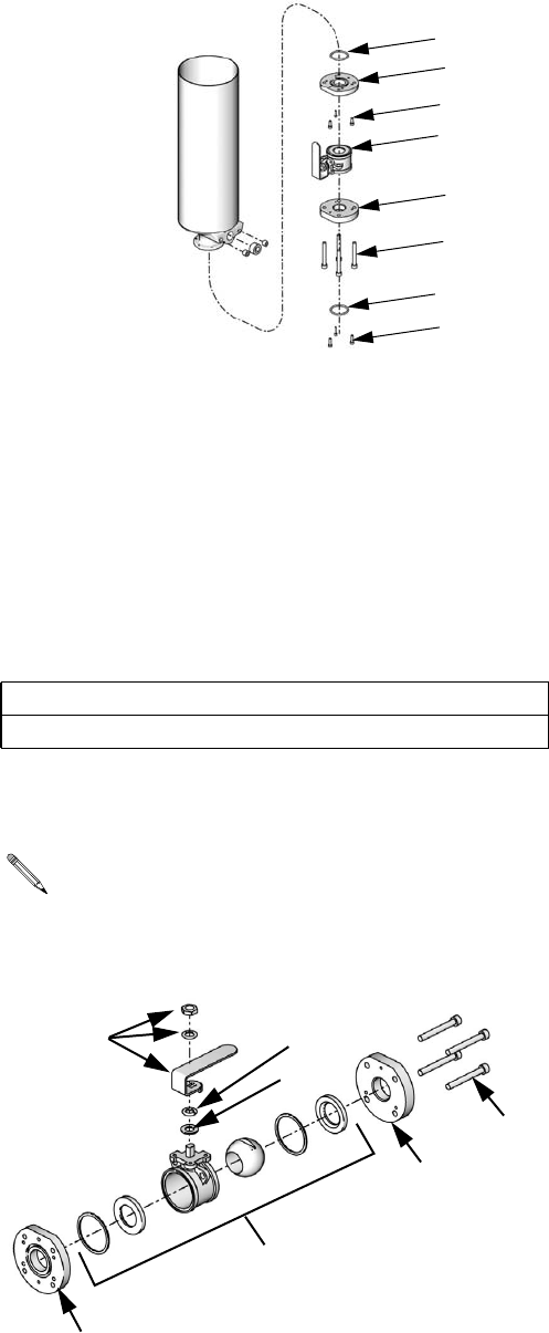
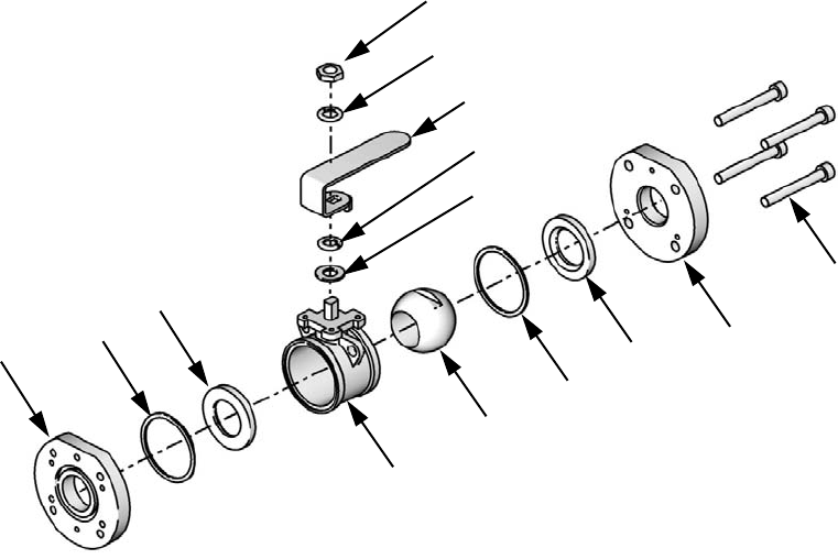
Ball Valve, Assembly 255280
2204a
2204b
2204c
2202
2201
2204g
2204f
2204e
2204d
2204h
2204j
2205 2206
2203
ti12564a
Ref Part Description Qty
2201 96/0075-1/99 WASHER, flat, sae, 7/16, mild steel, n series 1
2202 96/0075/99 WASHER, lock, split, 7/16, mild steel 1
2203 121012 SCREW, M8 x 1.25 65 mm, socket head cap
screw, stainless steel
4
2204 121111 VALVE, ball, 3 piece, 1-1/4 in. fp 1
2205 15M224 FLANGE, plate, top 1
2206 15M225 FLANGE, plate, bottom 1
Parts
312394V 41
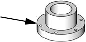
Flange Assembly, 256896
The flange assembly can be installed if no tanks or
accumulators are installed. It allows for other feed sys-
tem options to be installed onto the pump subassembly.
* Part not shown.
Ref Part Description Qty
2701 15M237 Flange, 1-1/2 in. npt 1
2702 * 95/0223/00 O-RING, fluoroelastomer, bbc 1
2703 * 120904 SCREW, socket head cap, M5
x0.8x18mm
3
ti12455a
2701
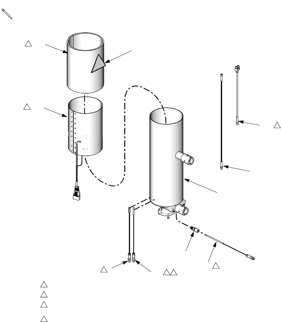
Parts
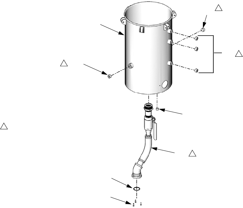
42 312394V
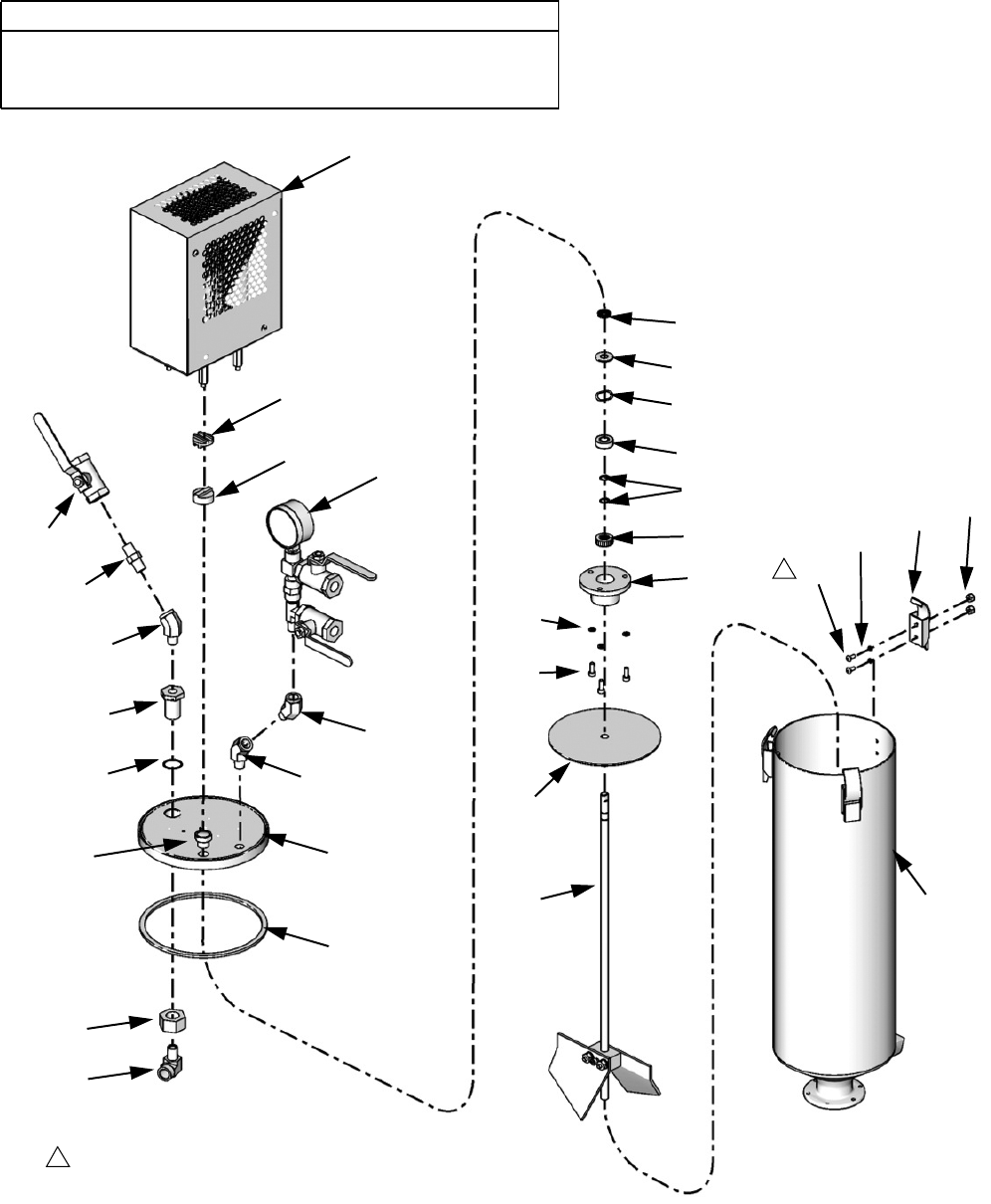
On-Board Stainless Steel Tank Lids
Lid Assemblies LC0019 to LC0026 and LC0130 to LC0132
CAUTION
The electric agitators used with on-board tanks will fail pre-
maturely when material viscosity exceeds 24,000 cps. Use
pneumatic agitators if material viscosity exceeds 24,000 cps.
1018
1019
1020
1021
1023
1021
1024
1009
1008
1007
1025
1026
1035
1022
1036
1017
1027
1028 1015
1016
1016
1010
1034
1033
1016
1030
1029
1031
1032
Secure screw inside tank with hex wrench and turn until secure. Do
not over tighten, o-ring will extrude.
1
1
Assembly LC0025 Shown
1011
1006
ti12459a
1005
(Tank
shown for
reference
only. Tanks
sold sepa-
rately.)

Parts
312394V 43
† Part not shown.
‡ Spare clamps will be provided with all clamp-down lid assemblies.
Ref Part Description
Quantity
LC0019, Lid assembly
with Relief
LC0020, Lid assembly
LC0021, Lid assembly,
120 V Agitator
LC0022, Lid assembly,
240 V Agitator
LC0023, Lid assembly,
Agitator, De-gas
LC0024, Lid assembly,
Agitator, De-gas
LC0025, Lid assembly,
Agitator, De-gas, Fill Port
LC0026, Lid assembly,
Agitator, De-gas, Fill Port
LC0130, Lid Assembly,
Pneumatic Agitator
LC0131, Clamp Down Lid,
Pneumatic Agitator, De-gas
LC0132, Clamp Down Lid,
Pneumatic Agitator, Fill Port
1005 --- Reference Only. Tank sold separately.‡ -----------
1006 95/0518/00 O-RING, fluoroelastomer, JJF 66666666666
1007 96/0282/98 FASTENER, screw, button head cap screw,
8-32 x 0.38, stainless steel 66666666666
1008 96/0820/98 CLAMP, over the center, stainless steel 33333333333
1009 96/0176-1/98 NUT, lock, 8-32, nylock, stainless steel 66666666666
1010 15M320 LID, 7L, 2 npt, 1 9/16-32 1 1
15M321 LID, 7L, 2 npt, 1 9/16-32, agitator 1111 11
15M322 LID, 7L, 2 npt, 9/16-32, agitator, fill port 11 1
1011 94/0752-D/97 VALVE, relief, 9/16-32, 5 psi 11111111111
1012 †94/0736/96 VALVE, drain cock, 1/4 npt, male, brass 111 1
1013 †94/0370/98 PLUG, socket head, 1/4 npt, stainless steel 111111 11
1014 †121090 FITTING, 1/4 npt expander 1
1015 255342 MANIFOLD, vacuum tree 11111 11
1016 94/0299/98 FITTING, elbow, str, 1/4 npt, 45, 3K 112223123
1017 255337 AGITATOR, motor assembly, 120V 111
255338 AGITATOR, motor assembly, 240V 111
02/1116/50 AGITATOR, assembly, pneumatic, TFM, 0.32 HP, 15:1 111
1018 95/0849/11 SEAL, posipak, 3/8 ID x 5/8 OD 111111111
1019 96/0733/87 WASHER, 3/8 x 7/8 x 0.062, PTFE 111111111
1020 97/2215/98 SPRING, wave, 0.86 x 0.65 x 0.010, stainless steel 111111111
1021 84/0120/98 BEARING, ball, 0.375ID, DS 222222222
1022 255339 AGITATOR, blade assembly 111111111
1023 96/0817/99 RING, retaining, external, 0.375, mild steel 222222222
1024 01/2212/70 HOUSING, bearing, electric agitator 111111111
1025 96/0005/98 WASHER, lock, #10, stainless steel 333333333
1026 96/0125/98 FASTENER, screw, socket head cap, 10-24X0.50,
stainless steel 333333333
1027 84/2215-B/11 COUPLING, alignment, 1 in. OD, disk, nylon 111111111
1028 84/2215-A/11 COUPLING, alignment, 1 in. OD, hub, 3/8 ID 111111111
1029 95/0117/00 O-RING, fluoroelastomer, jai 11 1
1030 01/1174-3/97 BULKHEAD, 1/4 npt, tank lid, thin, tfm 11 1
1031 96/0056/98 NUT, hex, jam, 3/4-16, stainless steel 11 1
1032 94/0300-1/98A FITTING, elbow, STRT, 90, 1/4 npt, male / female 11 1
1033 94/0320-1/99 FITTING, nipple, hex, 1/4npt, 5K, mild steel 11 1
1034 94/0900-R2/98 VALVE, ball, 2W, 1/4npt, female, 2000 psi 11 1
1035 87/0220-2/98 PLATE, slinger, tfm, 3/8ID, 5-1/2OD 11 1
1036 95/0524/01 GASKET, lid, tfm, nit 11111111111
Parts
44 312394V
Tanks for Use with Dust Covers
Tanks for Use with Clampdown Covers
Ball valve shutoff assemblies and mounting hard-
ware must be ordered separately.
LC0012
7.5 L stainless steel
LC0235
7.5 L stainless steel
with high level port
LC0013
3 L stainless steel
24U714
7.5 L stainless steel
with clamps
24U713
7.5 L stainless steel
with high level port
and clamps
24U715
3 L stainless steel
with clamps
Parts
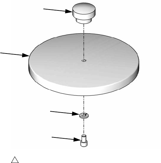
312394V 45
Lid Assembly LC0018
1302
1304
1301
1303
Apply thread sealant tape to male npt threads prior to installation.
1
ti12461a
Ref Part Description Qty
1301 15M956 LID, mod, 7.5L & 3L, stainless steel 1
1302 96/0127/98 FASTENER, socket head cap screw, 1/4-20 x
0.37, stainless steel
1
1303 96/0148/11 KNOB, 1/4-20, female, plastic 1
1304 96/0311/98 WASHER, lock, 1/4, hc, stainless steel 1
Parts
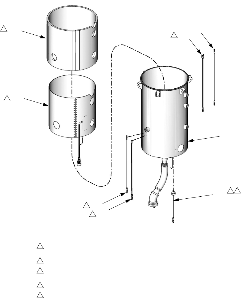
46 312394V
Off-Board Stainless Steel Tanks
Tank Assemblies LC0054 and LC0055
† Parts can be purchased in Tank Kit 255389 which includes the tank body, a basic tank lid with clamps, and a tank
lid gasket.
Parts can be purchased in Tank Kit 256633 which includes the tank body, a basic tank lid with clamps, and a tank
lid gasket.
601
601
606
601
602
605
603
604
Apply thread sealant tape to male
npt threads prior to installation.
1
1
1
1
1
Assembly LC0054 Shown
ti12454a
Ref Part Description Qty
601 111384 PLUG, pipe 5
602 103778 PLUG, pipe, headless 1
603 108832 O-RING 1
604 120904 SCREW, socket head cap, M5 x 0.8 x 18 mm 3
605 255391 SYSTEM, pipe and tube, 1-1/2 in. 1
606 †TANK, 30 L, stainless steel
(assembly LC0054 only)
1
TANK, 60 L, stainless steel
(assembly LC0055 only)
1
Parts
312394V 47
Tank Assemblies LC0259 and LC0260
408
407
401
404
405
406
402
403
Use glass cloth tape to secure ground strap, thermal switch, and RTD to tank wall
before adding heat blanket.
Secure heat blanket to tank with string laced through eyelets.
Insulation blanket should cover heat blanket completely. Secure insulation blanket to
tank with 2 in. wide velcro strap.
Apply thread sealant tape to male npt threads prior to installation.
The RTD sensor assembly (404) should always be connected to side one of the M8
splitter harness (407). Side one is on the female/female end of connector and is
marked with a molded imprint of the number “1”.
1
2
3
4
5
4
1
1
2
3
Assembly LC0259 Shown
5
5
ti12452a
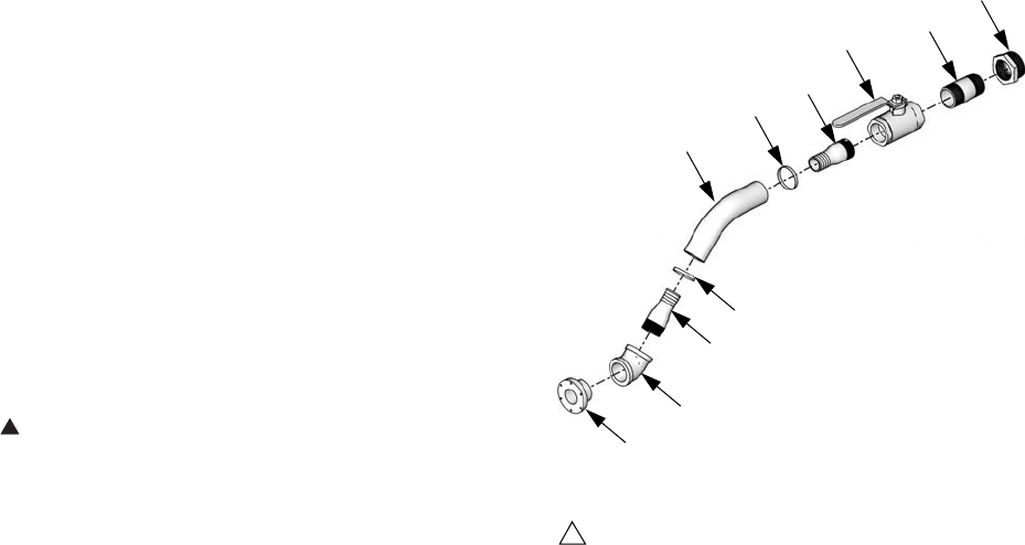
Parts
48 312394V
† Not shown. See Integrated Heat manual referenced
at the beginning of this manual.
▲Replacement Danger and Warning labels, tags, and
cards are available at no cost.
Pipe and Tube System, 255391
Ref Part Description Qty
401 LC0054 TANK, assy, 30 L, stainless steel
(assembly LC0259 only)
1
LC0055 TANK, assembly, 60 L, stainless
steel
(assembly LC0260 only)
402 LC0257 BLANKET, assy, heat, 30L, 240V,
GCA
(assembly LC0259 only)
1
LC0258 BLANKET, assy, heat, 60L, 240V,
GCA
(assembly LC0260 only)
403 257757 INSULATOR, blanket assy, 38 L
(assembly LC0259 only)
1
257758 INSULATOR, blanket assy, 75 L
(assembly LC0260 only)
403a 121208 LABEL, hot surface 1
404 257759 SENSOR, thermowell assy, RTD 1
405 256611 SENSOR, assy, 1.5 in. rtd, 4-pin
M8
1
406 256558 SWITCH, assy, thermal, 125C,
3P, M8
1
407 121615 HARNESS, splitter, M8, 4-pin
female/female/male, 3M
1
408 121682 CABLE, M8, 3-pin, male/female,
3 meter, molded
1
410 †121635 CIRCUIT, breaker, 2-pole, 13A, C
type
1
Ref Part Description Qty
2801 61/0056/88 HOSE, chemical, polyethyl-
ene,1-1/2 in.
1
2802 94/0910/98 FITTING, barb, 1-1/2 x 1-1/2
NPT, male, stainless steel
2
2803 94/1081/98 FITTING, elbow, 1-1/2 in.,
female, 45 deg, stainless steel
1
2804 94/0414/99 CLAMP, hose, 2-1/4 in. - 1-5/16
in., mild steel
2
2805 121135 VALVE, ball, 1-1/2 NPT full port 1
2806 121136 BUSHING, hex, 2 in. NPT x
1-1/2 in. NPT
1
2807 15M237 FLANGE,1-1/2 in. NPT 1
2808 15R536 FITTING, nipple, 1.5 NPT x 3 in.,
stainless steel
1
2801
2804
2802
2805 2808
2806
2807
2803
2802
2804
Apply thread sealant tape to all male npt threads.
1
ti12574a
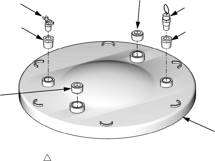
Parts
312394V 49
Off-Board Stainless Steel Tank Lids
Lid Assembly LC0101
Ref Part Description Qty
1101 111384 PLUG, pipe 2
1102 122767 BUSHING, 1/2 npt x 1/4 npt, stainless steel 2
1103 94/0736/96 VALVE, drain cock, 1/4 npt, male, brass 1
1104 15M578 LID, stainless steel 1
1105 15R145 VALVE, relief, 1/4 npt, male, 40 psi, sil 1
1105
1104
1103
1101
Apply thread sealant tape to all pipe threads.
1
ti14656a
1101
1102
1102
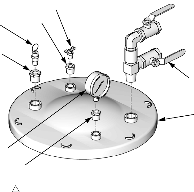
Parts
50 312394V
Lid Assembly LC0102
Ref Part Description Qty
1201 187875 GAUGE, pressure, fluid 1
1202 122767 BUSHING, 1/2 npt x 1/4 npt, stainless steel 2
1203 15M861 FITTING, reducer, pipe, 3/4 x 1/4, stainless
steel
1
1204 94/0736/96 VALVE, drain cock, 1/4 npt, male, brass 1
1205 257746 FITTING, vacuum tree 1
1206 15M578 LID 1
1207 15R145 VALVE, relief, 1/4 npt, male, 40 psi, sil 1
1207
Apply thread sealant tape to male npt threads prior to installation.
1
ti14722a
1203
1204
1202
1201
1202
1205
1206

Parts
312394V 51
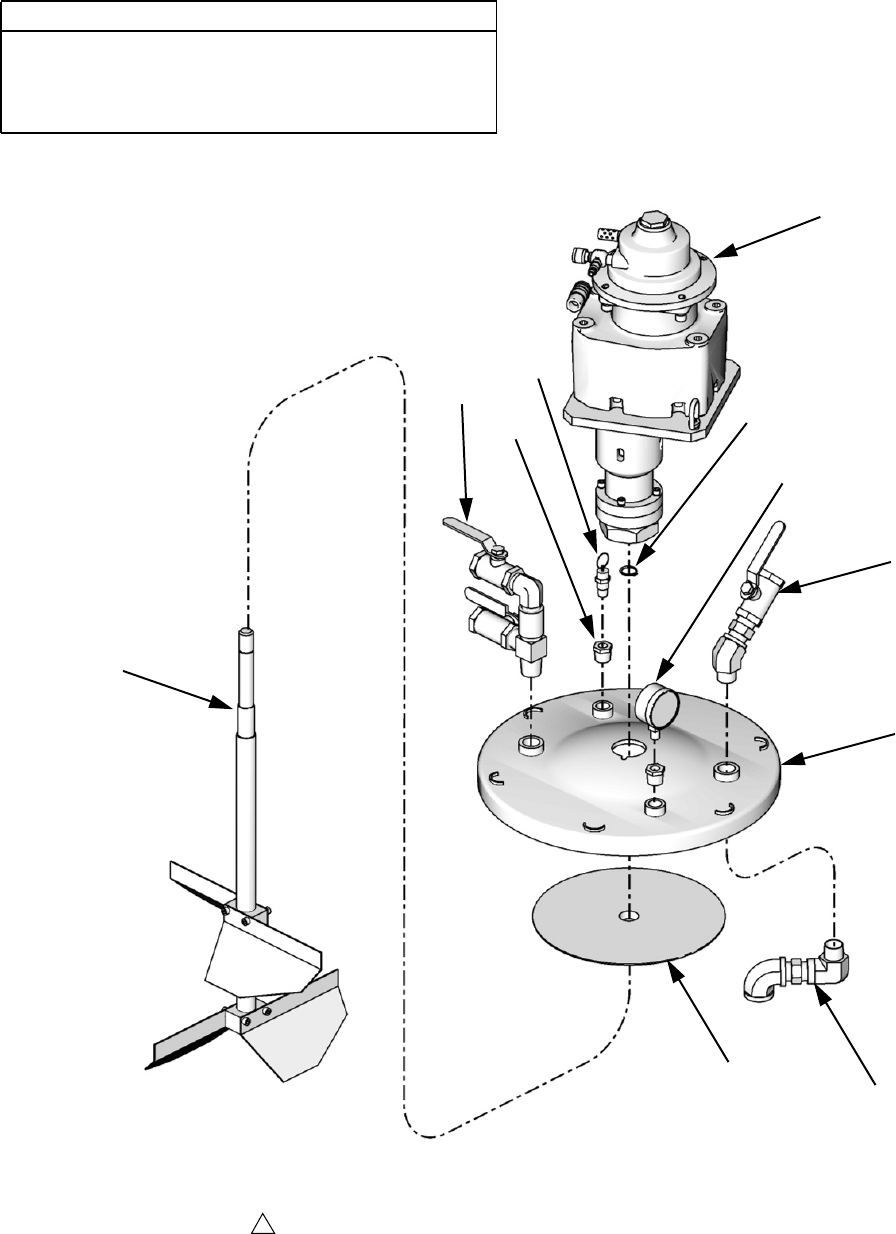
Parts
52 312394V
Lid Assemblies LC0050, LC0144, LC0145, LC0146, LC0147
CAUTION
The electric agitators used with off-board tanks will fail
prematurely when material viscosity exceeds
48,000 cps. Use pneumatic agitators if material vis-
cosity exceeds 48,000 cps.
1409
1401
1403
1407
1402
1410
1411
1406
1405
1408
1404
Apply thread sealant tape to male npt threads prior to installation.
1
Assembly LC0147 Shown
ti12460b

Parts
312394V 53
Previous versions of these lid assemblies include agitator 255670 but that agitator is no longer available. Agitator
kit 24J182 is the replacement for 255670.
Ref Part Description
Quantity
LC0050,
60 L,
Agitator,
Vacuum
De-gas
LC0144,
Pneumatic
Agitator,
De-gas
LC0145,
Pneumatic
Agitator,
De-gas,
60 L
LC0146,
Pneumatic
Agitator,
De-gas, Fill
Port,30L
LC0147,
Pneumatic
Agitator,
De-gas, Fill
Port, 60 L
140124J183 AGITATOR 1111
256822 MOTOR, single phase,
50/60 hz 1
1402 15M621 LID, agitator 1 1 1 1 1
1403 122776 RING, retaining, external,
0.750, mild steel 11111
1404 257607 AGITATOR, blade assem-
bly 1 1
257608 AGITATOR, blade assem-
bly 111
1405 122767 BUSHING, 1/2 x 1/4 npt,
male / female, stainless
steel, 6K, 316
22222
1406 15R145 VALVE, relief, 1/4 npt,
male, 40 psi, sil 11111
1407 187875 GAUGE, pressure, fluid 1 1 1 1 1
1408 257746 FITTING, vacuum tree 1 1 1 1 1
1409 257602 VALVE, assembly, ball, fill,
lid, 3/4, stainless steel 11
111384 PLUG, pipe 1 1 1
1410 255747 FITTING 11
1411 257606 PLATE, slinger 11
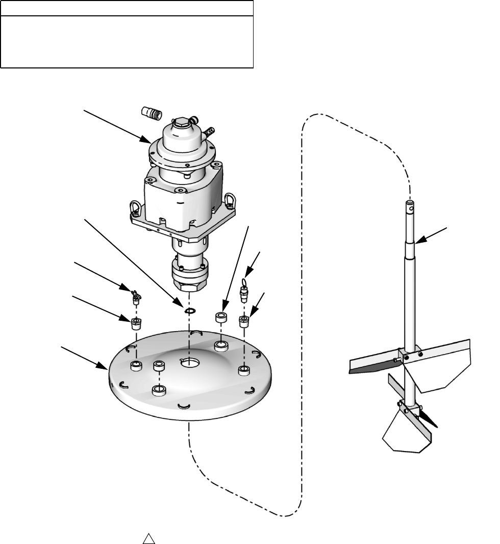
Parts
54 312394V
Lid Assemblies LC0042, LC0043, LC0142, and LC0143
CAUTION
The electric agitators used with off-board tanks will fail
prematurely when material viscosity exceeds
48,000 cps. Use pneumatic agitators if material vis-
cosity exceeds 48,000 cps.
1501
1505
1508
1506
1504
1503
1507
1506
1502
Apply thread sealant tape to male npt threads prior to installation.
1
Assembly LC0143 Shown
ti12464b

Parts
312394V 55
† Part not shown.
Previous versions of these lid assemblies include agitator 255670 but that agitator is no longer available. Agitator
kit 24J182 is the replacement for 255670.
Ref Part Description
Quantity
LC0042
30 L Lid
Assembly
LC0043
30 L Lid
Assembly
with De-gas
LC0142
30 L Lid
Assembly
with
Pneumatic
Agitator
LC0143
60 L Lid
Assembly
with
Pneumatic
Agitator
1501 255607 BLADE, assy, agitator 1
255608 BLADE, assy, agitator 1
1502 15M621 LID 11
15M578 LID 1 1
1503 122776 RING, retaining, external, 0.750,
mild steel 11
150424J183 AGITATOR 11
1505 187875 GAUGE, pressure, fluid 1
15M861 FITTING, 3/4 npt x 1/4 npt 1
111384 PLUG, pipe 2 22
1506 122767 BUSHING, 1/2 x 1/4 npt,
male/female, stainless steel, 6K,
316
2222
1507 94/0736/96 VALVE, drain cock, 1/4 npt, male,
brass 1111
1508 15R145 VALVE, relief, 1/4 npt, male, 40 psi,
sil 1111
1509 † 255746 FITTING, vacuum tree 1
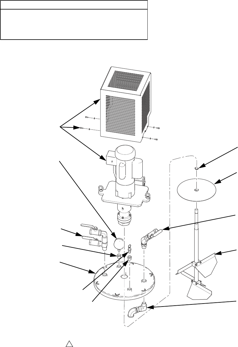
Parts
56 312394V
Lid Assemblies LC0047, LC0048, LC0051, LC0052
CAUTION
The electric agitators used with off-board tanks will fail
prematurely when material viscosity exceeds
48,000 cps. Use pneumatic agitators if material vis-
cosity exceeds 48,000 cps.
1608
Apply thread sealant tape to male npt threads prior to installation.
1
Assembly LC0051 Shown
ti17647a
1610
1603
1601
1609
1605
1607
1602
1604
1611
1607
1606

Parts
312394V 57
Ref Part Description
Quantity
LC0047,
LID, assy,
7.5 gal,
agit
LC0048,
LID, assy,
15 gal, agit
LC0051,
LID, assy,
7.5 gal,
agit, vac,
fill
LC0052,
LID, assy,
15 gal,
agit, vac,
fill
1601 15M621 LID, agitator 1 1 1 1
1602 256822 MOTOR, assy, single phase, 50/60hz 1 1 1 1
1603 257608 BLADE, assy agitator, 75l 1 1
257607 BLADE, assy, agitator, 38l 1 1
1604 257602 VALVE, assy, ball, fill, lid, 3/4, ss 1 1
125009 PLUG, pipe 2 2
1605 124400 GAUGE, pressure 1 1
94/0736/96 VALVE, drain cock, 1/4npt, m, brs 1 1
1606 257606 PLATE, slinger, 38l/75l 1 1
1607 122767 BUSHING, 1/2x1/4npt, mf, ss, 6k, 316 2 2 2 2
1608 122776 RING, ret, ext, 0.750, ms 1 1 1 1
1609 257746 FITTING, vacuum tree assy 1 1
1610 257747 FITTING, inner fill port assy 1 1
1611 15R145 VALVE, relief, 1/4npt, m, 40psi, sil 1 1 1 1
1612 U90331 TAPE, PTFE 1/2" wide 1 1 1 1
1613 070408 SEALANT, pipe 1 1
1614 070445 SEALANT, thread 1 1
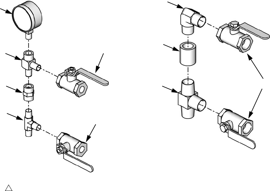
Parts
58 312394V
Vacuum Tree Manifold, 255342 Vacuum Tree Manifold, 257746
Ref Part Description Qty
2901 82/0220-1/11 GAUGE, 30 in. hg, 30 psi,
liquid filled
1
2902 94/0900-R2/99 VALVE, ball, 2-way, 1/4 npt,
female, 2K, mild steel
2
2903 121087 FITTING, tee,
male-male-male, 1/4 in.
NPT
1
2904 121088 FITTING, tee,
male-male-female, 1/4 in.
npt
1
2905 121089 FITTING, nipple, hex,
female-female, 1/4 in. npt
1
ti12575a
Apply thread sealant tape to male npt threads
prior to installation.
1
2902
2902
2901
2904
2905
2903
Ref Part Description Qty
3001 1228444 FITTING, tee, 3/4
npt, male, 3k
1
3002 122770 VALVE, ball, 3/4 npt,
female
2
3003 122769 COUPLING, 3/4 npt 1
3004 121116 FITTING, elbow,
3/4 npt, male/male,
right angle
1
ti12576a
3004
3003
3001 3002

Parts
312394V 59
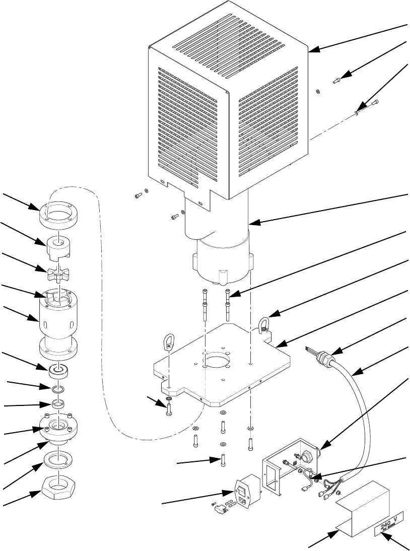
Parts
60 312394V
Stainless Steel Tank Agitators
Electric Agitator Motor Assembly, 256822
1701q
ti17646a
1701a
1701f
1701b
1701p
1701o
1701n
1701m
1701l
1701i
1701j
1701h
1701z
1701af
1701u 1701ag
1701j
1701g
1705
1707
1706
1701k
1701e,
1701t
1701c,
1701d
1701r,
1701s
1701z
1701x,
1701y,
1701aa
1701w,
1701ab,
1701ac,
1701ad,
1701ae,
1701v,
1702,
1703,
1704
Parts
312394V 61
▲Replacement Danger and Warning labels, tags, and
cards are available at no cost.
Ref Part Description Qty
1701 257605 HOUSING, agitator 1
. 1701a 124741 MOTOR, agitator 1
. 1701b 16K267 ADAPTER, plate, agitator
motor
1
. 1701c 158223 WASHER 4
. 1701d 108803 SCREW, hex 4
. 1701e 100021 SCREW, cap 2
. 1701f 122775 NUT, eye, 1/4-20 2
. 1701g 15Y358 HOUSING, upper, agitator 1
. 1701h 15V746 SPACER, agitator 1
. 1701i 122760 COUPLING, alignment 1
. 1701j 122761 HOSE, alignment 2
. 1701k 101885 SCREW, cap 4
. 1701l 122774 BEARING, ball 2
. 1701m 15Y360 SPACER, seal, shaft 1
. 1701n 122772 SEAL 1
. 1701o 15Y357 HOUSING, lower 1
. 1701p 15Y363 GASKET 1
. 1701q 15Y355 NUT, shaft 1
Ref Part Description Qty
. 1701r 105510 WASHER, lock 4
. 1701s 112222 SCREW, cap 4
. 1701t 100985 WASHER, lock 2
. 1701u 15R328 JUNCTION BOX, motor
switch
1
. 1701v 111307 WASHER, lock 2
. 1701w 102598 SCREW, cap 2
. 1701x 120910 SOCKET, electrical 1
. 1701y 120916 SCREW 2
. 1701z 121172 GRIP, cord 2
. 1701aa 115142 FUSE, 5.0 amp, time lag 2
. 1701ab▲125008 LABEL, earth ground 1
. 1701ac 121013 SCREW, socket head 1
. 1701ad 120993 NUT, hex 3
. 1701ae 24H375 HARNESS, ground 1
. 1701af 24H376 HARNESS, power 1
.1701ag▲15X092 LABEL, 240 volts 1
1702 124442 TERMINAL, ring 1
1703 124437 CAP, splice 4
1704 124436 CONNECTOR, splice 4
1705 24K356 COVER, motor 1
1706 116876 WASHER 4
1707 102598 SCREW, cap 4
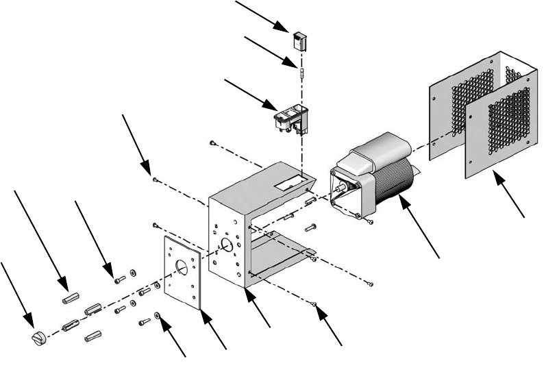
Parts
62 312394V
Electric Agitator Motor, Assemblies 255337 and 255338
† Part not shown.
2509
2501
2513
2511
2505
2502
2506
2508
2507
2511
2512 2504
2503
Assembly 255337 Shown
ti12584a
Ref Part Description Qty
2501 01/1198-2/97 FASTENER, standoff, agitator, hd, elec, alu 4
2502 01/2218/97 ENCLOSURE, agitator, electric, prmv/f, hd 1
2504 01/2219/97 PLATE, adapter, electric agitator, hd, prm 1
2505 81/2218-1/11 MOTOR, 50 rpm, 60 in-lb, 120V, 1.2A
(assembly 255337 only)
1
256613 MOTOR, assembly, 50 rpm, 60 in-lb, 230V
(assembly 255338 only)
1
2506 81/1040/11 MODULE, AC, 2P, 250V, 10A, double pull sin-
gle throw, with fuse
1
2507 81/1040-1/11 MODULE, AC conn, 2p, 250V, 10A, with bar 1
2508 81/1053-1.6/11 FUSE,5x20mm,1.6A, time delay 1
2509 84/2215-A/11 COUPLING, alignment, 1 in. OD, HUB,
3/8 in. ID
1
2510 96/0212/99 FASTENER, button head cap screw,
10-24 x 0.50, mild steel
4
2511 96/0271/99 FASTENER, button head cap screw, 8-32 x
0.31, mild steel
8
2512 120907 WASHER, plain #10 4
2513 120961 SCREW, button head cap screw, 10-32 x
1.25 in., stainless steel
4
2514 † 121599 CORD, power, v-lock, C14/C13, 10A 1
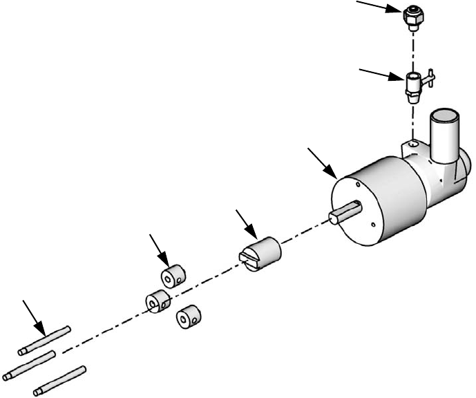
Parts
312394V 63
Pneumatic Agitator Motor Assembly, 02/1116/50
2605
2604
2601
2602
2606
2603
ti12585a
Ref Part Description Qty
2601 82/0216/11 MOTOR, pneumatic, agitator, 0.32 hp 1
2602 01/1189/98 ADAPTER, coupling, air motor, agitator 1
2603 01/1168/98 SHAFT, mount, pneumatic gear, agitator,
stainless steel
3
2604 94/0838/96 VALVE, needle, 1/8 npt x 1/8 npt,
male/female
1
2605 94/0702/96 FITTING, 1/4 tube x 1/8 npt, male, brass 1
2606 01/1179/98 ADAPTER, shaft, mounting, air motor 3
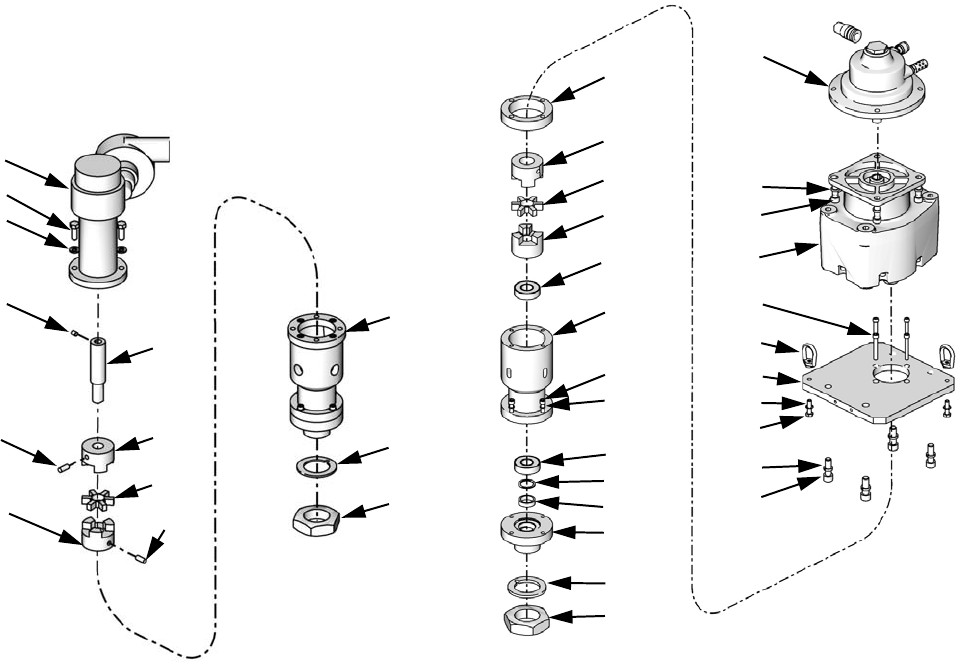
Parts
64 312394V
Pneumatic Agitator Motor, 255670
NOTE: This agitator assembly is no longer available.
Piece parts from the assembly can be ordered but if the
entire assembly is needed then agitator kit 24J182 must
be ordered.
--- Not available for sale.
Pneumatic Agitator Motor, 24J183
Ref Part Description Qty
1801 --- MOTOR, pneumatic, agitator,
0.5 hp, 15:1
1
1802 15Y355 NUT, agitator, 1.75-16, 7/8
shaft
1
1803 01/1487/01 GASKET, mating, agitator
housing, asme, buna
1
1804 01/1492/98 SHAFT, extension, air motor
coupler
1
1805 15Y358 HOUSING, agitator, pneumatic 1
1806 5-06-0706 SCREW, shs, 5/16-18 x 0.38,
cup point
1
1807 84/1480/11 COUPLING, alignment,
2.11 OD, disk, TPE
1
1808 84/1481/11 COUPLING, alignment,
2.11 in. OD, hub, 3/4 ID
2
1809 96/0038/99 SCREW, hex head cap, 3/8-16
x 1.00, mild steel, grade 5
2
1810 96/0046/99 WASHER, lock, split, 3/8, mild
steel
2
1811 96/0455-1/99 SCREW, socket head cap,
5/16-18 x 0.75, cup point
2
1805
1803
1802
1811
1801
1806
1811
1808
1804
1808
1807
1809
1810
ti12466a
Ref Part Description Qty
2201 121953 GEAR REDUCER, 56c, 27.8 ratio,
2 stage
1
2202 106115 WASHER, lock, hi-collar 4
2203 C19837 SCREW, cap, socket head 4
2204 15V745 ADAPTER, plate, agitator motor 1
2205 112600 WASHER, lock, spring, hi-collar 4
2206 125012 SCREW, socket head, 7/16-14 x
1.25
4
2207 100021 SCREW, hex head cap 2
2208 122775 NUT, eye, 1/4-20, mild steel 2
2209 121963 COUPLER, agitator motor, 1 in. 1
2210 15Y358 HOUSING, upper, agitator, electric 1
2211 15V746 SPACER, agitator motor 1
2212 122760 COUPLING, alignment, disk, TPE 1
2213 122761 HOSE, alignment, hub 1
2214 101885 SCREW, cap, sch 4
2215 122774 BEARING, ball, 3/4 bore x
1-3/4 dia. x 1/2
2
2216 15Y360 SPACER, seal, shaft, agitator 1
2217 122772 SEAL, 0.875 x 1.125, ptfe 1
2218 15Y357 HOUSING, lower, agitator, electric 1
2219 15Y363 GASKET, mating, agitator housing 1
2220 15Y355 NUT, agitator, shaft, 1.75-16 1
2221 105510 WASHER, lock, spring hi-collar 4
2222 112222 SCREW, cap, sch 4
2223 100985 WASHER, lock 2
2224 24J181 MOTOR, air 1
2225 070269 SEALANT, anaerobic 1
2211
2224
2202
2203
2201
2214
2208
2204
2207
2205
2206
2223
2209
2212
2213
2215
2210
2222
2221
2215
2216
2217
2218
2219
2220 ti15109a
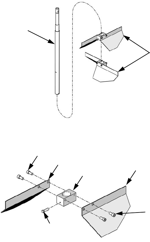
Parts
312394V 65
Agitator Blade Assemblies 257607 and 257608
1902
1901
Assembly 257607 Shown
ti12468a
1901c
1901b
1901a 1901b
1901c
1901d
ti12474a
Ref Part Description Qty
1901 257604 BLADE, assy, electric agitator 2
1901a 15Y362 BLOCK, blade, coupler, 1 in. diameter 1
1901b 15Y361 BLADE, agitator 2
1901c 551903 FASTENER, socket head cap screw,
1/4-20 x 0.50, stainless steel
4
1901d 122778 FASTENER, square head, 1/4-20 x
0.75, stainless steel
1
1902 15M624 SHAFT, blade assy
(assembly 257607 only)
1
15M625 SHAFT, blade assy
(assembly 257608 only)
1
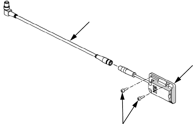
Parts
66 312394V
Level Sensors
Polyethylene Tanks Level Sensors,
Assembly LC0278
2001
2003
2002
ti12470b
Ref Part Description Qty
2001 123549 SENSOR, level, quick disconnect 2
2002 121686 CABLE, M8 x M8, 4P, female / male,
straight/right angle, 2 m
2
2003 96/1000/99 FASTENER, screw, socket head cap,
M3 x 8, mild steel
4
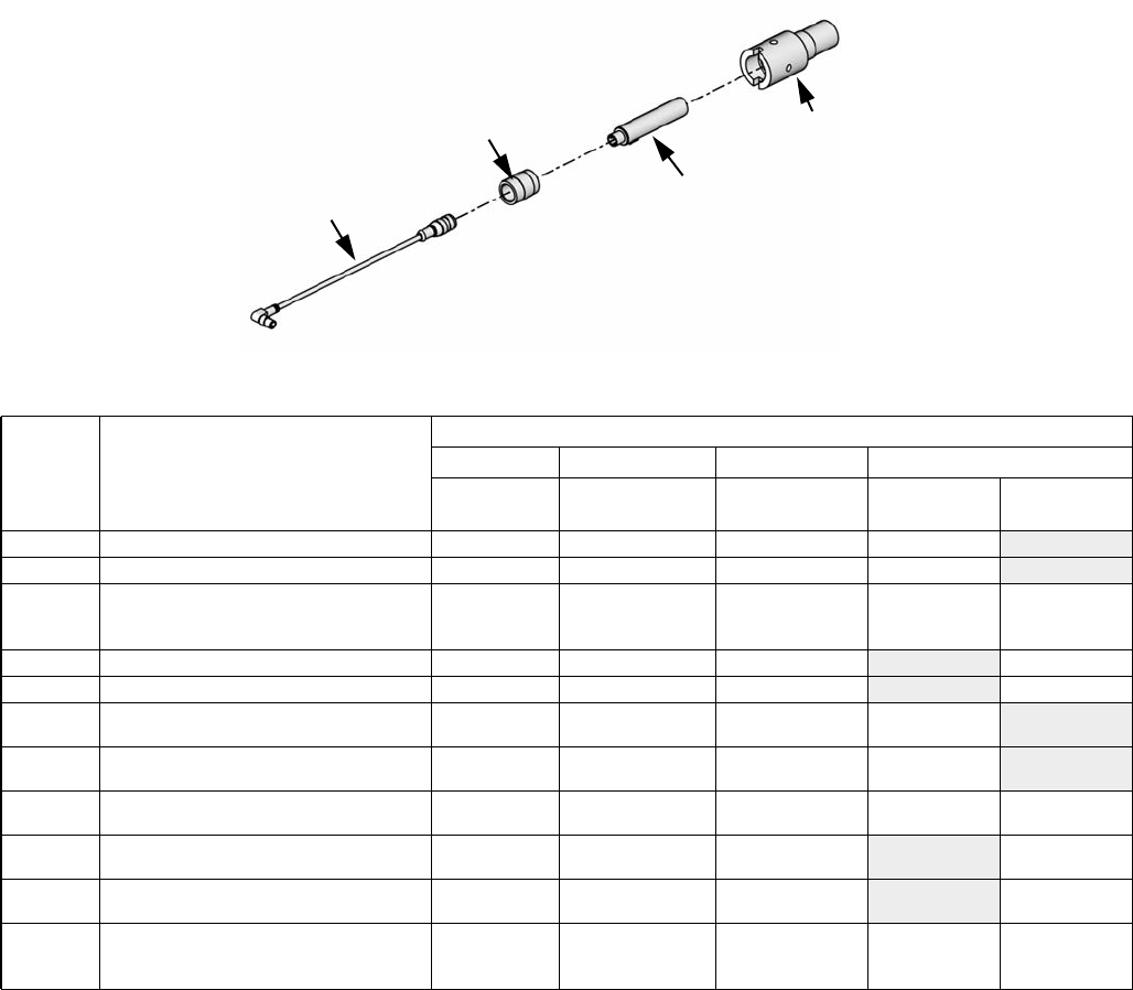
Parts
312394V 67
Stainless Steel Tanks Level Sensors
2102
2101
2103
2104
ti12469a
Sensor
Package Description
Reference Number, Description, Quantity
2101 2102 2103 2104
121511
Level Sensor
01/0025-EF/87
Level Sensor Well
15U978
Sensor Well Cap
121684
CABLE, 2 m
121694
CABLE, 3 m
LC0279 Low level sensor for two 7.5 L tanks 22 22
LC0280 Low level sensor for one 7.5 L tank 11 11
LC0281
Low level sensor for one 7.5 L tank and
one low level sensor for one 30 L or 60 L
tank
22 211
LC0282 Low level sensor for two 30 or 60 L tanks 22 2 2
LC0283 Low level sensor for one 30 or 60 L tank 11 1 1
LC0284 High and low level sensors for two 7.5 L
tanks 44 44
LC0285 High and low level sensors for one 7.5 L
tank 22 22
LC0286 High and low level sensors for one 30 or
60 L, Low level sensors for one 7.5 L tank 33 312
LC0287 High and low level sensors for two 30 or
60 L tanks 44 4 4
LC0288 High and low level sensors for one 30 or
60 L tank 22 2 2
LC0289 High and low level sensors for one 30 or
60 L tank, high and low level sensors for
one 7.5 L tank
44 422

Kits
68 312394V
Kits
Mixer and Shroud Options
MD2 Valve Kits
Machine Rebuild Kits
Tank Accessories
† Item includes only the pump. A vacuum kit must be pur-
chased to install the pump onto the tank.
Kit includes all parts needed to connect a nitrogen tank
to the material tank.
Part Description
LC0063 Mixer, 3/16 in. (6.5 mm) x 32, 10 Mixers
with shroud
LC0057 Mixer, 1/4 in. (6.5 mm) x 24, 10 Mixers
with shroud
LC0058 Mixer, 3/8 in. (9.8 mm) x 24, 10 Mixers
with shroud
LC0059 Mixer, 3/8 in. (9.8 mm) x 36, 10 Mixers
with shroud
LC0060 Mixer, 3/8 in. (9.8 mm) Combo, 10 Mixers
with shroud
LC0061 Mixer, 3/16 in. (4.8 mm) x 32 Luer Lock, 10
Mixers with shroud
LC0062 Mixer, 1/4 in. (6.5 mm) x 24 Luer Lock, 10
Mixers with shroud
LC0077 Mixer, 3/16 in. (4.8 mm) x 32, 50 Mixers
LC0078 Mixer, 1/4 in. (6.5 mm) x 24, 50 Mixers
LC0079 Mixer, 3/8 in. (9.8 mm) x 24, 50 Mixers
LC0080 Mixer, 3/8 in. (9.8 mm) x 36, 50 Mixers
LC0081 Mixer, 3/8 in. (9.8 mm) combo, 50 Mixers
LC0083 Mixer, 1/4 in. (6.5 mm) x 24 Luer Lock, 50
Mixers
LC0082 Mixer, 3/16 in. (4.8 mm) x 32 Luer Lock, 50
Mixers
LC0084 Mixer, 3/16 in. (4.8 mm) x 32, 250 Mixers
LC0085 Mixer, 1/4 in. (6.5 mm) x 24, 250 Mixers
LC0086 Mixer, 3/8 in. (9.8 mm) x 24, 250 Mixers
LC0087 Mixer, 3/8 in. (9.8 mm) x 36, 250 Mixers
LC0088 Mixer, 3/8 in. (9.8 mm) combo, 250 Mixers
LC0089 Mixer, 3/16 in. (4.8 mm) x 32 Luer Lock,
250 Mixers
LC0090 Mixer, 1/4 in. (6.5 mm) x 24 Luer Lock, 250
Mixers
See MD2 Dispense Valve instruction manual refer-
enced at the beginning of this manual for installa-
tion instructions or for more information.
Part Description
255217 MD2, kit rebuild, air cylinder
255218 MD2, kit rebuild, back-end of wet section
(no needle or seat)
255219 MD2, Soft Seat rebuild, needle and nose
255220 MD2, convert Soft Seat nose to Hard Seat
(Hard Seat rebuild), needle and nose
See the PR70 and PR70v Repair - Parts manual
referenced at the beginning of this manual for parts
included in each kit.
Part Description
LC0091 3.0 in. Air Cylinder rebuild kit
LC0092 4.5 in. Air Cylinder rebuild kit
LC0093 Check Valve rebuild kit, Stainless Steel Ball
LC0318 Check Valve rebuild kit, Carbide Ball
LC0094 Rear Pump Seal rebuild kit
Part Description
LC0097 Desiccant Dryer, 3/8 in. NPT with adapter
and cartridge
LC0098 Desiccant Dryer refill cartridge
LC0095 Nitrogen Harness Kit for 30 L and 60 L
tank, 1 tank
LC0096 Nitrogen Harness Kit for 30 L and 60 L
tank, 2 tanks
†LC0099 Vacuum Transfer Pump, 120V, down to 25
Torr
†LC0100 Vacuum Transfer Pump, 240V, down to 25
Torr

Kits
312394V 69
Vacuum Kits
These vacuum kits contain the parts necessary to
attach a vacuum pump to the tanks.
Refill Kits
Refill Kits 256659 and 256660 are designed to turn on
and off a transfer pump as needed to keep the tanks at
the proper fluid level. Tank Refill Kit 256577 is designed
to open and close a valve to allow fluid to flow into the
tank from an always-on transfer pump. Tank Refill
Kit 256577 includes the parts necessary to install on the
base or lid of a 7.5 L, 30 L, or 60 L tank.
External Control Interface Connection Kit
Part Description
256205 Vacuum Kit, Single On-Board Tank
256206 Vacuum Kit, Two On-Board Tanks
256207 Vacuum Kit, Single Off-Board Tank
256209 Vacuum Kit, Two Off-Board Tanks
Assembly 256206
Shown
Assembly 256207
Shown
On-Board
Vacuum Kits
Off-Board
Vacuum Kits
ti12588a ti12589a
Part Description
256659 Refill Kit, 1/4 npt, solenoid, 24V
256660 Refill Kit, 1/2 npt, solenoid, 24V
256577 Tank Refill Kit
Part Description
LC0008 Cord, I/O interface and splitter
Assembly 256659
Shown
Assembly 256577 shown
installed on tank for reference
ti12590a
ti12591a
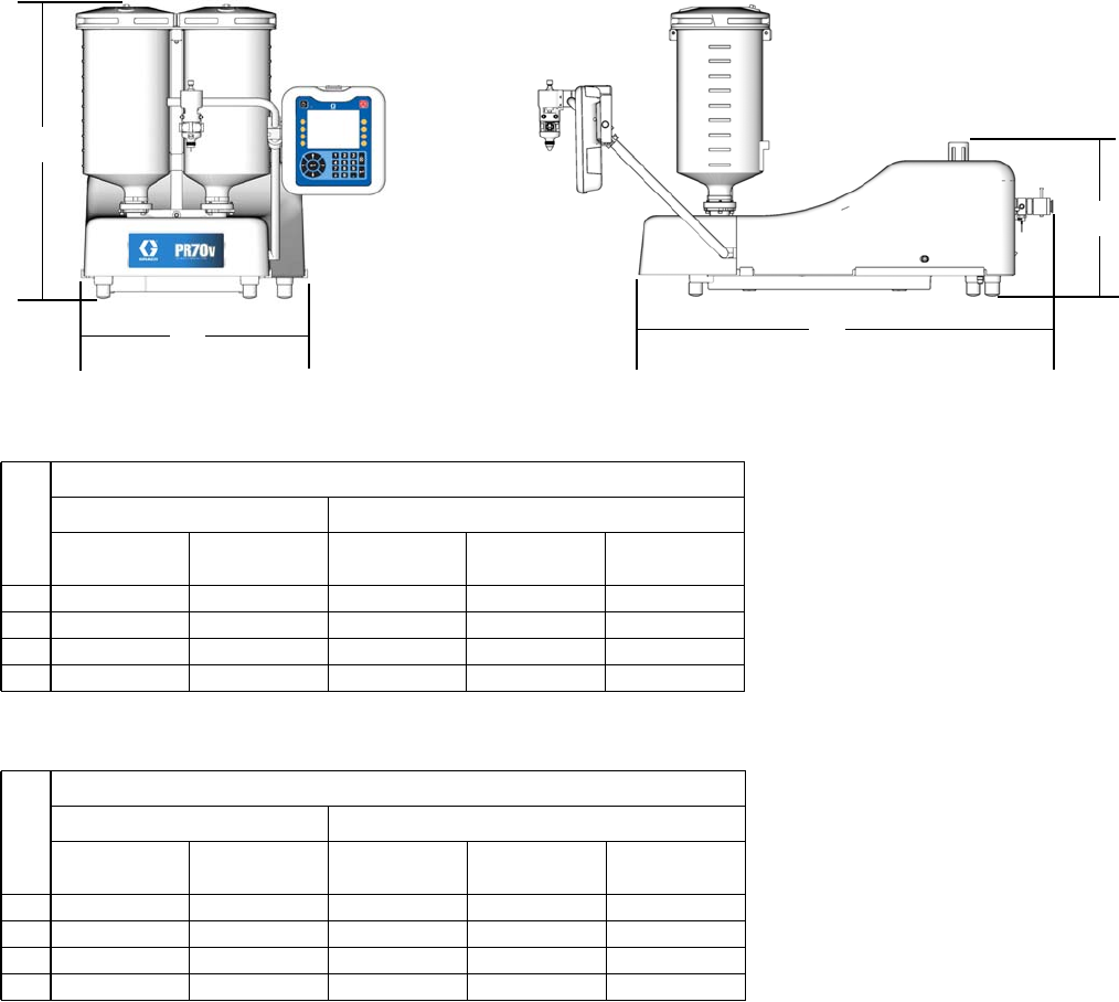
Dimensions
70 312394V
Dimensions
Machine with On-Board Tanks
PR70
PR70v
† Assembly dimensions listed are maximum for all assemblies under the given title.
On-board stainless steel tank dimensions include ball valves and vacuum de-gas in maximum height calculation.
B
A
C
D
ti12621b ti12622b
Ref
† Assembly Dimensions, in. (mm)
Polyethylene Tanks Stainless Steel Tanks
No Agitators With Agitators 3 L 7.5 L, No
Agitators
7.5 L, with
Agitators
A 26.4 (670) 38.6 (980) 28.2 (716) 38.2 (970) 39.9 (1013)
B 18.5 (470) 18.5 (470) 15.5 (394) 15.5 (394) 15.5 (394)
C 30.6 (778) 30.6 (778) 30.6 (778) 30.6 (778) 30.6 (778)
D 13.4 (340) 13.4 (340) 13.4 (340) 13.4 (340) 13.4 (340)
Ref
† Assembly Dimensions, in. (mm)
Polyethylene Tanks Stainless Steel Tanks
No Agitators With Agitators 3L,No
Agitators
7.5 L, No
Agitators
7.5 L, with
Agitators
A 30.0 (762) 39.4 (1001) 29.0 (737) 39.0 (991) 40.6 (1031)
B 20.9 (531) 20.9 (531) 20.9 (531) 20.9 (531) 20.9 (531)
C 38.6 (980) 38.6 (980) 38.6 (980) 38.6 (980) 38.6 (980)
D 14.3 (363) 14.3 (363) 14.3 (363) 14.3 (363) 14.3 (363)
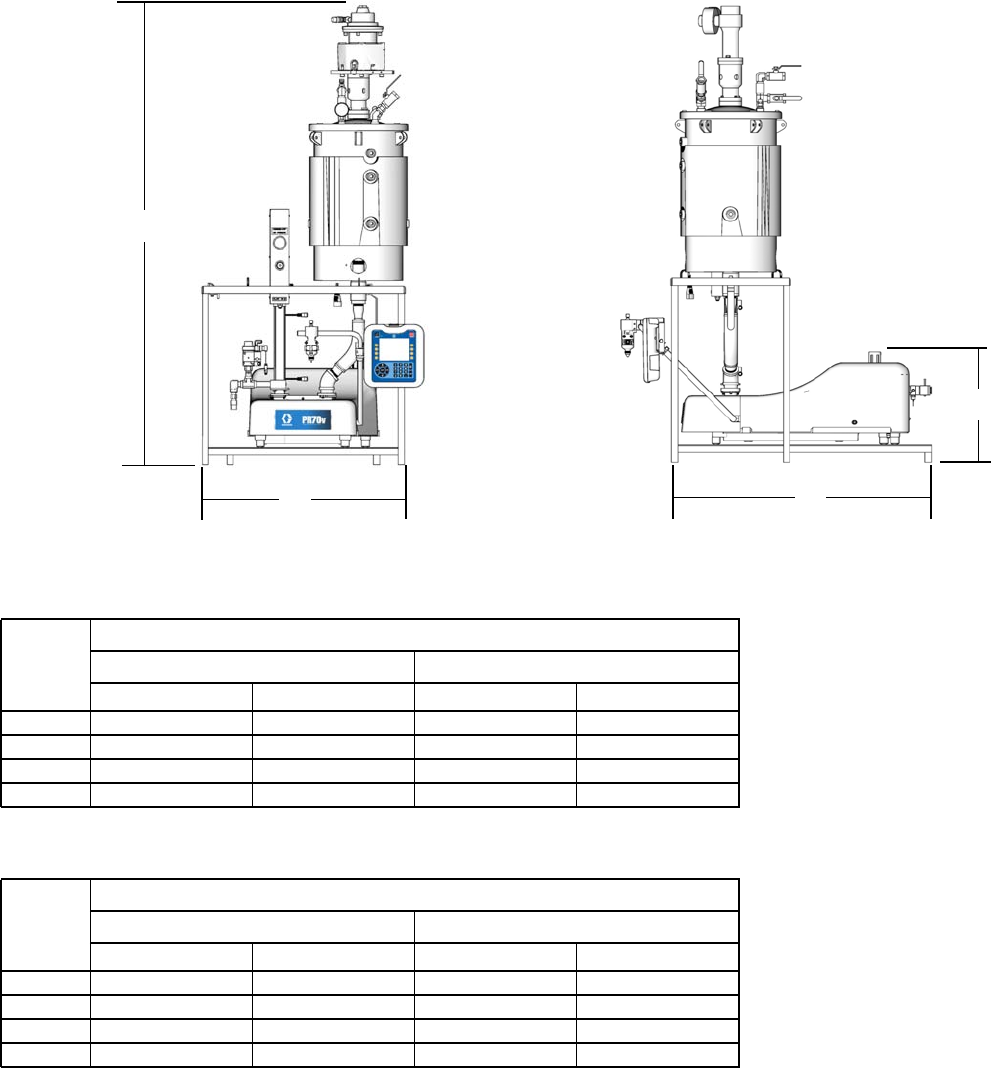
Dimensions
312394V 71
Machine with Off-Board Tanks
PR70
PR70v
† Assembly dimensions listed are maximum for all assemblies under the given title.
C
B
A
D
ti12623c ti12624c
Ref
† Assembly Dimensions, in. (mm)
30 L Tank 60 L Tank
No Agitators With Agitators No Agitators With Agitators
A 55.7 (1415) 83.4 (2118) 64.9 (1648) 89.5 (2273)
B 32.1 (815) 32.1 (815) 32.1 (815) 32.1 (815)
C 29.3 (236) 29.3 (236) 29.3 (236) 29.3 (236)
D 16.0 (406) 16.0 (406) 16.0 (406) 16.0 (406)
Ref
† Assembly Dimensions, in. (mm)
30 L Tank 60 L Tank
No Agitators With Agitators No Agitators With Agitators
A 55.7 (1415) 83.4 (2118) 64.9 (1648) 89.5 (2273)
B 32.1 (815) 32.1 (815) 32.1 (815) 32.1 (815)
C 40.1 (1019) 40.1 (1019) 40.1 (1019) 40.1 (1019)
D 17.0 (432) 17.0 (432) 17.0 (432) 17.0 (432)

Technical Data
312394V 73
Technical Data
Metering Pump Effective Area ..................... 80 to 960 mm2(0.124 to 1.49 in.2) per side
Small Air Cylinder Effective Area ................... 4560 mm2(7.07 in.2)
Large Air Cylinder Effective Area .................. 10260 mm2(15.9 in.2)
Maximum Stroke Length ......................... 38.1 mm (1.50 in.)
Minimum Stroke Length ......................... 5.8mm(0.23 in.)
Volume per Cycle .............................. 2 to 70 cc (0.12 to 4.3 in.3)
Pump Cycles per 1 L (0.26 gal) .................... 14.3 to 500 cycles (varies by piston size)
Ratios (fixed) .................................. 1:1to12:1 (depending upon cylinders selected)
Maximum Fluid Working Pressure .................. 3000 psi (20.7 MPa, 207 bar)
Maximum Air Input Pressure ...................... 100psi(0.7 MPa, 7 bar)
Maximum Cycle Rate ........................... 30cpm
Maximum Operating Temperature .................. 70°C (160°F), nylon pistons 50°C (120°F) UHMWPE pis-
tons or PE Tanks
Air Inlet Size .................................. 1/4NPTfemale
Pump Fluid Outlet Size .......................... -03, -04, -06, -08 or –12 JIC fittings for 3/16 in. (4.8 mm),
1/4 in. (6.4 mm), 3/8 in. (9.5 mm), 1/2 in. (12.7 mm),
3/4 in. (19.1 mm) hoses
Wetted Parts .................................. 303/304, 17-4 PH, hard chrome, Chromex™, carbide,
Chemical Resistant O-rings, PTFE, nylon, UHMWPE
Weight ....................................... 55kg(120 lb) typical with two 7.5 L tanks
150 kg (330 lb) typical with two 60 L tanks
Sound Pressure Level (at typical operator station for
machine mounted Dispense Valve ................. 82dBA
Compressed Air ................................ Less than 10 scfm typical (varies with cycle times)
Electrical Power ................................ • 100-240 V 50/60Hz, 1 phase for machine – 80 Watts
• 208-240V 50/60Hz, 1 phase for heat – 11 kW max
• 120 or 240 VAC 50/60Hz 1 phase for on-board agita-
tors, 80 Watts
• 240 VAC 50/60Hz 1 phase for off-board agitators,
600 Watts

Graco Standard Warranty
74 312394V
Graco Standard Warranty
Graco warrants all equipment referenced in this document which is manufactured by Graco and bearing its name to be free from defects in
material and workmanship on the date of sale to the original purchaser for use. With the exception of any special, extended, or limited warranty
published by Graco, Graco will, for a period of twelve months from the date of sale, repair or replace any part of the equipment determined by
Graco to be defective. This warranty applies only when the equipment is installed, operated and maintained in accordance with Graco’s written
recommendations.
This warranty does not cover, and Graco shall not be liable for general wear and tear, or any malfunction, damage or wear caused by faulty
installation, misapplication, abrasion, corrosion, inadequate or improper maintenance, negligence, accident, tampering, or substitution of
non-Graco component parts. Nor shall Graco be liable for malfunction, damage or wear caused by the incompatibility of Graco equipment with
structures, accessories, equipment or materials not supplied by Graco, or the improper design, manufacture, installation, operation or
maintenance of structures, accessories, equipment or materials not supplied by Graco.
This warranty is conditioned upon the prepaid return of the equipment claimed to be defective to an authorized Graco distributor for verification of
the claimed defect. If the claimed defect is verified, Graco will repair or replace free of charge any defective parts. The equipment will be returned
to the original purchaser transportation prepaid. If inspection of the equipment does not disclose any defect in material or workmanship, repairs will
be made at a reasonable charge, which charges may include the costs of parts, labor, and transportation.
THIS WARRANTY IS EXCLUSIVE, AND IS IN LIEU OF ANY OTHER WARRANTIES, EXPRESS OR IMPLIED, INCLUDING BUT NOT LIMITED
TO WARRANTY OF MERCHANTABILITY OR WARRANTY OF FITNESS FOR A PARTICULAR PURPOSE.
Graco’s sole obligation and buyer’s sole remedy for any breach of warranty shall be as set forth above. The buyer agrees that no other remedy
(including, but not limited to, incidental or consequential damages for lost profits, lost sales, injury to person or property, or any other incidental or
consequential loss) shall be available. Any action for breach of warranty must be brought within two (2) years of the date of sale.
GRACO MAKES NO WARRANTY, AND DISCLAIMS ALL IMPLIED WARRANTIES OF MERCHANTABILITY AND FITNESS FOR A
PARTICULAR PURPOSE, IN CONNECTION WITH ACCESSORIES, EQUIPMENT, MATERIALS OR COMPONENTS SOLD BUT NOT
MANUFACTURED BY GRACO. These items sold, but not manufactured by Graco (such as electric motors, switches, hose, etc.), are subject to
the warranty, if any, of their manufacturer. Graco will provide purchaser with reasonable assistance in making any claim for breach of these
warranties.
In no event will Graco be liable for indirect, incidental, special or consequential damages resulting from Graco supplying equipment hereunder, or
the furnishing, performance, or use of any products or other goods sold hereto, whether due to a breach of contract, breach of warranty, the
negligence of Graco, or otherwise.
FOR GRACO CANADA CUSTOMERS
The Parties acknowledge that they have required that the present document, as well as all documents, notices and legal proceedings entered into,
given or instituted pursuant hereto or relating directly or indirectly hereto, be drawn up in English. Les parties reconnaissent avoir convenu que la
rédaction du présente document sera en Anglais, ainsi que tous documents, avis et procédures judiciaires exécutés, donnés ou intentés, à la suite
de ou en rapport, directement ou indirectement, avec les procédures concernées.
Graco Information
For the latest information about Graco products, visit www.graco.com.
TO PLACE AN ORDER, contact your Graco distributor or call to identify the nearest distributor.
Toll Free: 1-800-746-1334 or Fax: 330-966-3006
All written and visual data contained in this document reflects the latest product information available at the time of publication.
Graco reserves the right to make changes at any time without notice.
)RUSDWHQWLQIRUPDWLRQVHHZZZJUDFRFRPSDWHQWV
Original instructions. This manual contains English. MM 312394
Graco Headquarters: Minneapolis
International Offices: Belgium, China, Japan, Korea
GRACO INC. AND SUBSIDIARIES • P.O. BOX 1441 • MINNEAPOLIS MN 55440-1441 • USA
Copyright 2007, Graco Inc. All Graco manufacturing locations are registered to ISO 9001.
www.graco.com
Revised February 2014
