Graco 312760S Pr70 And Pr70V Users Manual PR70v, Repair Parts, English
2015-04-02
: Graco Graco-312760S-Pr70-And-Pr70V-Users-Manual-685886 graco-312760s-pr70-and-pr70v-users-manual-685886 graco pdf
Open the PDF directly: View PDF ![]() .
.
Page Count: 86
- Related Manuals
- Product Configurator
- Warnings
- Grounding
- Pressure Relief Procedure
- Shutdown
- Troubleshooting
- Electrical Schematics
- Repair
- Parts
- Fixed Ratio Base, LC0262, LC0263, LC0264, LC0265
- Fixed Ratio Frame Sub-Assembly, LC0290
- Fixed Ratio Drive Block Assembly, LC0107
- Variable Ratio Base, LC0242, LC0243, LC0244, LC0245
- Variable Ratio Frame Sub-Assembly, LC0232
- Air Cylinder, LC0110, LC0111, LC0230, LC0231
- Pump Sub-Assembly, LC0112
- Control Bracket, LC0240, LC0261
- Incoming Power Bracket, LC0239
- Piston Package
- Nylon and UHMW Piston Replacement Kits
- Controls
- Applicator Mounting
- Dispense Valve
- Mixers
- Hose Packages
- Power Cords
- Flow Monitoring
- Tank Stands, Assemblies LC0247 and LC0103
- Heat Zone Assemblies
- Kits
- Dimensions
- Technical Data
- Graco Standard Warranty
- Graco Information
Repair - Parts
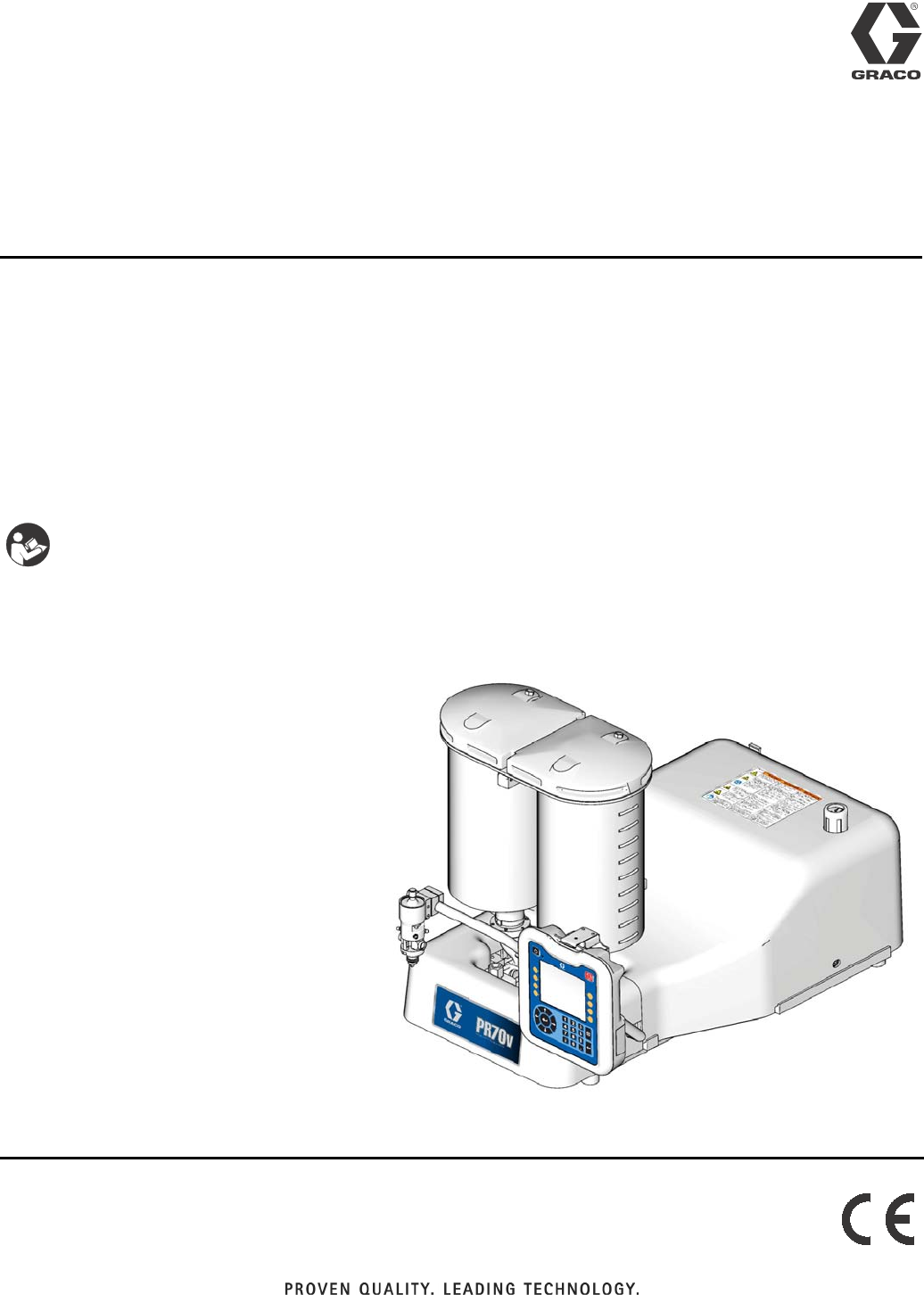
PR70 and PR70v
Two Component Liquid Dispensing Systems
Fixed or variable ratio systems. For accurate metering, mixing, and dispensing of
two-component materials. For professional use only.
Not approved for use in European explosive atmosphere locations.
3000 psi (21 MPa, 207 bar) Maximum Working Pressure
100 psi (0.7 MPa, 7 bar) Maximum Air Inlet Pressure
Important Safety Instructions
Read all warnings and instructions in all
supplied manuals. Save these instructions.
ti12385b
PR70v Shown with Advanced Display Module
312760S
EN
2312760S
Contents
Related Manuals . . . . . . . . . . . . . . . . . . . . . . . . . . . 3
Product Configurator . . . . . . . . . . . . . . . . . . . . . . . 4
Warnings . . . . . . . . . . . . . . . . . . . . . . . . . . . . . . . . 11
Grounding . . . . . . . . . . . . . . . . . . . . . . . . . . . . . . . 14
Pressure Relief Procedure . . . . . . . . . . . . . . . . . . 14
Models with Advanced Display Module . . . . . . . 14
Models with Standard Display Module . . . . . . . 14
Shutdown . . . . . . . . . . . . . . . . . . . . . . . . . . . . . . . . 14
Troubleshooting . . . . . . . . . . . . . . . . . . . . . . . . . . . 16
Error Codes
(Advanced Display Module) . . . . . . . . . . . . 18
Error Codes
(Standard Display Module) . . . . . . . . . . . . . 23
Electrical Schematics . . . . . . . . . . . . . . . . . . . . . . 25
Repair . . . . . . . . . . . . . . . . . . . . . . . . . . . . . . . . . . . 29
HydraCheck Kit Installation . . . . . . . . . . . . . . . . 29
Air Cylinder Kit Installation . . . . . . . . . . . . . . . . 31
Rear Pump Rebuild Kit Installation . . . . . . . . . . 33
Piston/Cylinder Replacement Kit Installation . . 35
Check Valve Rebuild Kit Installation . . . . . . . . . 36
Piston Plug Installation . . . . . . . . . . . . . . . . . . . 37
Pressure Transducer Installation . . . . . . . . . . . . 37
Flow Meter Installation . . . . . . . . . . . . . . . . . . . 38
Fluid Control Module Replacement . . . . . . . . . . 39
Fuse Replacement . . . . . . . . . . . . . . . . . . . . . . 40
Parts . . . . . . . . . . . . . . . . . . . . . . . . . . . . . . . . . . . . 41
Fixed Ratio Base, LC0262, LC0263, LC0264,
LC0265 . . . . . . . . . . . . . . . . . . . . . . . . . . . . 41
Fixed Ratio Frame Sub-Assembly, LC0290 . . . . 44
Fixed Ratio Drive Block Assembly, LC0107 . . . . 45
Variable Ratio Base, LC0242, LC0243, LC0244,
LC0245 . . . . . . . . . . . . . . . . . . . . . . . . . . . . 46
Variable Ratio Frame Sub-Assembly, LC0232 . . 49
Air Cylinder, LC0110, LC0111, LC0230, LC0231 52
Pump Sub-Assembly, LC0112 . . . . . . . . . . . . . . 54
Control Bracket, LC0240, LC0261 . . . . . . . . . . . 56
Incoming Power Bracket, LC0239 . . . . . . . . . . . 58
Piston Package . . . . . . . . . . . . . . . . . . . . . . . . . 60
Nylon and UHMW Piston Replacement Kits . . . 63
Controls . . . . . . . . . . . . . . . . . . . . . . . . . . . . . . . 64
Applicator Mounting . . . . . . . . . . . . . . . . . . . . . . 65
Dispense Valve . . . . . . . . . . . . . . . . . . . . . . . . . 66
Mixers . . . . . . . . . . . . . . . . . . . . . . . . . . . . . . . . 68
Hose Packages . . . . . . . . . . . . . . . . . . . . . . . . . 69
Power Cords . . . . . . . . . . . . . . . . . . . . . . . . . . . 76
Flow Monitoring . . . . . . . . . . . . . . . . . . . . . . . . . 77
Tank Stands, Assemblies LC0247 and LC0103 79
Heat Zone Assemblies . . . . . . . . . . . . . . . . . . . 79
Kits . . . . . . . . . . . . . . . . . . . . . . . . . . . . . . . . . . . . . 80
Dimensions . . . . . . . . . . . . . . . . . . . . . . . . . . . . . . . 82
Machine with On-Board Tanks . . . . . . . . . . . . . . 82
Machine with Off-Board Tanks . . . . . . . . . . . . . . 83
Technical Data . . . . . . . . . . . . . . . . . . . . . . . . . . . . 84
Graco Standard Warranty . . . . . . . . . . . . . . . . . . . 86
Graco Information . . . . . . . . . . . . . . . . . . . . . . . . . 86

Related Manuals
312760S 3
Related Manuals
PR70 and PR70v Operation and Parts Manuals
Part Description
3A0429 PR70 with Standard Display Module Operation and
Maintenance Manual
312759 PR70 and PR70v with Advanced Display Module
Operation and Maintenance Manual
312760 PR70 and PR70v Repair and Parts Manual
312394 PR70 and PR70v Feed Systems Manual
312761 PR70v Integrated Heat Instructions - Parts Manual
MD2 Dispense Valve Manual
Part Description
312185 MD2 Dispense Valve Instructions and Parts Manual
Product Configurator
4312760S
Product Configurator
An example of the product configurator would be the following configurator code.
The following part number fields apply for the PR70 and PR70v part numbering configurator fields. Shaded items
listed in the configurator table below are “Super Standard” items that are typically stocked and provide the best deliv-
ery dates.
PR7F------------------
Code: A B-C D-E F G-H I-J K L M N O P Q R S T U V
Air Motor
High Volume Side Piston
Low Volume Side Piston
Controls
High Volume Side Hose
Low Volume Side Hose
Dispense Valve
Mixer
Applicator Mounting
Power Cord
Flow Monitoring
High Volume Side Tank
High Volume Side Tank Cover
Low Volume Side Tank
Low Volume Side Tank Cover
Tank Level Sensors
Heat Zone Controller
Off-Board Tank Stand
PR7F-J-A5-A5-E-A6-A6-3-1-2-A-N-3-N-H-N-6-N-N
Code: A B-C D-E F G-H I-J K L M N O P Q R S T U V
Air Motor
High Volume Side Piston
Low Volume Side Piston
Controls
High Volume Side Hose
Low Volume Side Hose
Dispense Valve
Mixer
Applicator Mounting
Power Cord
Flow Monitoring
High Volume Side Tank
High Volume Side Tank Cover
Low Volume Side Tank
Low Volume Side Tank Cover
Tank Level Sensors
Heat Zone Controller
Off-Board Tank Stand
Code A Part Air Motor
A LC0262 PR70 with 3.0 in. (4.56 mm) Air Motor
B LC0264 PR70 with 4.5 in. (10.26 mm) Air Motor
C LC0263 PR70 with 3.0 in. (4.56 mm) Air Motor
and Hydracheck
D LC0265 PR70 with 4.5 in. (10.26 mm) Air Motor
and Hydracheck
F LC0242 PR70v with 3.0 in. (4.56 mm) Air Motor
G LC0244 PR70v with 4.5 in. (10.26 mm) Air
Motor
H LC0243 PR70v with 3.0 in. (4.56 mm) Air Motor
and Hydracheck
J LC0245 PR70v with 4.5 in. (10.26 mm) Air
Motor and Hydracheck
Code B Part
High Volume Side Piston and
Metering Tube Material
A LC1___ Nylon Piston, Stainless Steel Metering
Tube (last three digits of part number
is the mm2 piston size)
B LC2___ UHMWPE Piston, Stainless Steel
Metering Tube (last three digits of part
number is the mm2 piston size)
C LC3___ UHMWPE Piston, Ceramic Metering
Tube (last three digits of part number
is the mm2 piston size)
Code C Part High Volume Piston Size (mm2)
180, Available in Nylon Only
2 100, Available in Nylon Only
3120, Available in Nylon Only

Product Configurator
312760S 5
4 140, Available in Nylon Only
5160
6 180
7 200
8 220
9240
A 260
B 280
C 300
F320
G 360
H 400
J 440
L480
M 520
R 560
S 600
T640
U 720
W 800
X 880
Y960
Z Custom High Volume side, consult fac-
tory (stainless steel only)
Code D Part
High Volume Side Piston and
Metering Tube Material
A LC1___ Nylon Piston, Stainless Steel Metering
Tube (last three digits of part number
is the mm2 piston size)
B LC2___ UHMWPE Piston, Stainless Steel
Metering Tube (last three digits of part
number is the mm2 piston size)
C LC3___ UHMWPE Piston, Ceramic Metering
Tube (last three digits of part number
is the mm2 piston size)
Code E Part Low Volume Side Piston Size (mm2)
180, Available in Nylon Only
2 100, Available in Nylon Only
3120, Available in Nylon Only
4 140, Available in Nylon Only
5160
6 180
7 200
8 220
9240
A 260
B 280
C 300
F320
G 360
H 400
J440
L480
M520
R560
S600
T640
U720
W800
X880
Y960
Z Custom Low Volume side, consult fac-
tory (stainless steel only)
Code F Part Controls
B LC0272 Standard Display Module with 1 Fluid
Control Module
D LC0274 Advanced Display Module with 1 Fluid
Control Module
E LC0275 Advanced Display Module with 2 Fluid
Control Modules
Codes
G-H,
I-J Part
High Volume Hose /
Low Volume Hose
A1 LC0801 3/16 in. (4.8 mm) - 2.5 ft (0.6 m)
A2 LC0802 3/16 in. (4.8 mm) - 10 ft (3.0 m)
A3 LC0803 3/16 in. (4.8 mm) - 15 ft (4.6 m)
A4 LC0804 1/4 in. (6.5 mm) - 2.5 ft (0.6 m)
A5 LC0805 1/4 in. (6.5 mm) - 10 ft (3.0 m)
A6 LC0806 1/4 in. (6.5 mm) - 15 ft (4.6 m)
A7 LC0807 3/8 in. (9.5 mm) - 2.5 ft (0.6 m)
A8 LC0808 3/8 in. (9.5 mm) - 10 ft (3.0 m)
A9 LC0809 3/8 in. (9.5 mm) - 15 ft (4.6 m)
AA LC0810 1/2 in. (13 mm) - 2.5 ft (0.6 m)
AB LC0811 1/2 in. (13 mm) - 10 ft (3.0 m)
AC LC0812 1/2 in. (13 mm) - 15 ft (4.6 m)
AG LC0813 3/4 in. (19 mm) - 10 ft (3.0 m)
AH LC0814 3/4 in. (19 mm) - 15 ft (4.6 m)
B4 LC0881 Heated, 1/4 in. (6.5 mm) - 2.5 ft (0.6 m)
B5 LC0882 Heated, 1/4 in. (6.5 mm) - 10 ft (3.0 m)
B6 LC0883 Heated, 1/4 in. (6.5 mm) - 15 ft (4.6 m)
B7 LC0884 Heated, 3/8 in. (9.5 mm) - 2.5 ft (0.6 m)
B8 LC0885 Heated, 3/8 in. (9.5 mm) - 10 ft (3.0 m)
B9 LC0886 Heated, 3/8 in. (9.5 mm) - 15 ft (4.6 m)
BA LC0887 Heated, 1/2 in. (13 mm) - 2.5 ft (0.6 m)
BB LC0888 Heated, 1/2 in. (13 mm) - 10 ft (3.0 m)
BC LC0889 Heated, 1/2 in. (13 mm) - 15 ft (4.6 m)
BG LC0890 Heated, 3/4 in. (19 mm) - 10 ft (3.0 m)
BH LC0891 Heated, 3/4 in. (19 mm) - 15 ft (4.6 m)
C1 LC0161 Recirculating, On-Board Tanks,
3/16 in. (4.8 mm) - 2.5 ft (0.6 m)
C2 LC0162 Recirculating, On-Board Tanks,
3/16 in. (4.8 mm) - 10 ft (3.0 m)

Product Configurator
6312760S
C3 LC0163 Recirculating, On-Board Tanks,
3/16 in. (4.8 mm) - 15 ft (4.6 m)
C4 LC0164 Recirculating, On-Board Tanks,
1/4 in. (6.5 mm) - 2.5 ft (0.6 m)
C5 LC0165 Recirculating, On-Board Tanks,
1/4 in. (6.5 mm) - 10 ft (3.0 m)
C6 LC0166 Recirculating, On-Board Tanks,
1/4 in. (6.5 mm) - 15 ft (4.6 m)
C7 LC0167 Recirculating, On-Board Tanks,
3/8 in. (9.5 mm) - 2.5 ft (0.6 m)
C8 LC0168 Recirculating, On-Board Tanks,
3/8 in. (9.5 mm) - 10 ft (3.0 m)
C9 LC0169 Recirculating, On-Board Tanks,
3/8 in. (9.5 mm) - 15 ft (4.6 m)
CA LC0170 Recirculating, On-Board Tanks,
1/2 in. (13 mm) - 2.5 ft (0.6 m)
CB LC0171 Recirculating, On-Board Tanks,
1/2 in. (13 mm) - 10 ft (3.0 m)
CC LC0172 Recirculating, On-Board Tanks,
1/2 in. (13 mm) - 15 ft (4.6 m)
CD LC0173 Recirculating, On-Board Tanks,
3/4 in. (19 mm) - 10 ft (3.0 m)
CE LC0174 Recirculating, On-Board Tanks,
3/4 in. (19 mm) - 15 ft (4.6 m)
D1 LC0175 Recirculating, Off-Board Tanks,
3/16 in. (4.8 mm) - 2.5 ft (0.6 m)
D2 LC0176 Recirculating, Off-Board Tanks,
3/16 in. (4.8 mm) - 10 ft (3.0 m)
D3 LC0177 Recirculating, Off-Board Tanks,
3/16 in. (4.8 mm) - 15 ft (4.6 m)
D4 LC0178 Recirculating, Off-Board Tanks,
1/4 in. (6.5 mm) - 2.5 ft (0.6 m)
D5 LC0179 Recirculating, Off-Board Tanks,
1/4 in. (6.5 mm) - 10 ft (3.0 m)
D6 LC0180 Recirculating, Off-Board Tanks,
1/4 in. (6.5 mm) - 15 ft (4.6 m)
D7 LC0181 Recirculating, Off-Board Tanks,
3/8 in. (9.5 mm) - 2.5 ft (0.6 m)
D8 LC0182 Recirculating, Off-Board Tanks,
3/8 in. (9.5 mm) - 10 ft (3.0 m)
D9 LC0183 Recirculating, Off-Board Tanks,
3/8 in. (9.5 mm) - 15 ft (4.6 m)
DA LC0184 Recirculating, Off-Board Tanks,
1/2 in. (13 mm) - 2.5 ft (0.6 m)
DB LC0185 Recirculating, Off-Board Tanks,
1/2 in. (13 mm) - 10 ft (3.0 m)
DC LC0186 Recirculating, Off-Board Tanks,
1/2 in. (13 mm) - 15 ft (4.6 m)
DD LC0187 Recirculating, Off-Board Tanks,
3/4 in. (19 mm) - 10 ft (3.0 m)
DE LC0188 Recirculating, Off-Board Tanks,
3/4 in. (19 mm) - 15 ft (4.6 m)
E1 LC0190 Recirculating, Heated, On-Board
Tanks, 1/4 in. (6.5 mm) - 2.5 ft (0.6 m)
E2 LC0191 Recirculating, Heated, On-Board
Tanks, 1/4 in. (6.5 mm) - 10 ft (3.0 m)
E3 LC0192 Recirculating, Heated, On-Board
Tanks, 1/4 in. (6.5 mm) - 15 ft (4.6 m)
E4 LC0193 Recirculating, Heated, On-Board
Tanks, 3/8 in. (9.5 mm) - 2.5 ft (0.6 m)
E5 LC0194 Recirculating, Heated, On-Board
Tanks, 3/8 in. (9.5 mm) - 10 ft (3.0 m)
E6 LC0195 Recirculating, Heated, On-Board
Tanks, 3/8 in. (9.5 mm) - 15 ft (4.6 m)
E7 LC0196 Recirculating, Heated, On-Board
Tanks, 1/2 in. (13 mm) - 2.5 ft (0.6 m)
E8 LC0197 Recirculating, Heated, On-Board
Tanks, 1/2 in. (13 mm) - 10 ft (3.0 m)
E9 LC0198 Recirculating, Heated, On-Board
Tanks, 1/2 in. (13 mm) - 15 ft (4.6 m)
EA LC0199 Recirculating, Heated, On-Board
Tanks, 3/4 in. (19 mm) - 10 ft (3.0 m)
EB LC0200 Recirculating, Heated, On-Board
Tanks, 3/4 in. (19 mm) - 15 ft (4.6 m)
F1 LC0201 Recirculating, Heated, Off-Board
Tanks, 1/4 in. (6.5 mm) - 2.5 ft (0.6 m)
F2 LC0202 Recirculating, Heated, Off-Board
Tanks, 1/4 in. (6.5 mm) - 10 ft (3.0 m)
F3 LC0203 Recirculating, Heated, Off-Board
Tanks, 1/4 in. (6.5 mm) - 15 ft (4.6 m)
F4 LC0204 Recirculating, Heated, Off-Board
Tanks, 3/8 in. (9.5 mm) - 2.5 ft (0.6 m)
F5 LC0205 Recirculating, Heated, Off-Board
Tanks, 3/8 in. (9.5 mm) - 10 ft (3.0 m)
F6 LC0206 Recirculating, Heated, Off-Board
Tanks, 3/8 in. (9.5 mm) - 15 ft (4.6 m)
F7 LC0207 Recirculating, Heated, Off-Board
Tanks, 1/2 in. (13 mm) - 2.5 ft (0.6 m)
F8 LC0208 Recirculating, Heated, Off-Board
Tanks, 1/2 in. (13 mm) - 10 ft (3.0 m)
F9 LC0209 Recirculating, Heated, Off-Board
Tanks, 1/2 in. (13 mm) - 15 ft (4.6 m)
FA LC0210 Recirculating, Heated, Off-Board
Tanks, 3/4 in. (19 mm) - 10 ft (3.0 m)
FB LC0211 Recirculating, Heated, Off-Board
Tanks, 3/4 in. (19 mm) - 15 ft (4.6 m)
GA LC0400 High Pressure, 3/8 in. (9.5 mm) - 2.5 ft
(0.6 m)
GB LC0401 High Pressure, 3/8 in. (9.5 mm) - 10 ft
(3.0 m)
GC LC0402 High Pressure, 3/8 in. (9.5 mm) - 15 ft
(4.6 m)
GD LC0403 High Pressure, 1/2 in. (13 mm) - 2.5 ft
(0.6 m)
GE LC0404 High Pressure, 1/2 in. (13 mm) - 10 ft
(3.0 m)
GF LC0405 High Pressure, 1/2 in. (13 mm) - 15 ft
(4.6 m)

Product Configurator
312760S 7
GH LC0406 High Pressure, 3/4 in. (19 mm) - 10 ft
(3.0 m)
GJ LC0407 High Pressure, 3/4 in. (19 mm) - 15 ft
(4.6 m)
GK LC0432 High Pressure, Recirculating,
On-Board Tanks,
3/8 in. (9.5 mm) - 2.5 ft (0.6 m)
GL LC0433 High Pressure, Recirculating,
On-Board Tanks,
3/8 in. (9.5 mm) - 10 ft (3.0 m)
GM LC0434 High Pressure, Recirculating,
On-Board Tanks,
3/8 in. (9.5 mm) - 15 ft (4.6 m)
GQ LC0435 High Pressure, Recirculating,
On-Board Tanks,
1/2 in. (13 mm) - 2.5 ft (0.6 m)
GR LC0436 High Pressure, Recirculating,
On-Board Tanks,
1/2 in. (13 mm) - 10 ft (3.0 m)
GS LC0437 High Pressure, Recirculating,
On-Board Tanks,
1/2 in. (13 mm) - 15 ft (4.6 m)
GT LC0438 High Pressure, Recirculating,
On-Board Tanks,
3/4 in. (19 mm) - 10 ft (3.0 m)
GU LC0439 High Pressure, Recirculating,
On-Board Tanks,
3/4 in. (19 mm) - 15 ft (4.6 m)
GW LC0440 High Pressure, Recirculating,
On-Board Tanks,
3/8 in. (9.5 mm) - 2.5 ft (0.6 m)
GX LC0441 High Pressure, Recirculating,
On-Board Tanks,
3/8 in. (9.5 mm) - 10 ft (3.0 m)
GY LC0442 High Pressure, Recirculating,
On-Board Tanks,
3/8 in. (9.5 mm) - 15 ft (4.6 m)
G1 LC0443 High Pressure, Recirculating,
On-Board Tanks,
1/2 in. (13 mm) - 2.5 ft (0.6 m)
G2 LC0444 High Pressure, Recirculating,
On-Board Tanks,
1/2 in. (13 mm) - 10 ft (3.0 m)
G3 LC0445 High Pressure, Recirculating,
On-Board Tanks,
1/2 in. (13 mm) - 15 ft (4.6 m)
G4 LC0446 High Pressure, Recirculating,
On-Board Tanks,
3/4 in. (19 mm) - 10 ft (3.0 m)
G5 LC0447 High Pressure, Recirculating,
On-Board Tanks,
3/4 in. (19 mm) - 15 ft (4.6 m)
HA LC0472 High Pressure, Heated, 3/8 in. (9.5
mm) - 2.5 ft (0.6 m)
HB LC0473 High Pressure, Heated, 3/8 in. (9.5
mm) - 10 ft (3.0 m)
HC LC0474 High Pressure, Heated, 3/8 in. (9.5
mm) - 15 ft (4.6 m)
HF LC0475 High Pressure, Heated, 1/2 in. (13
mm) - 2.5 ft (0.6 m)
HG LC0476 High Pressure, Heated, 1/2 in. (13
mm) - 10 ft (3.0 m)
HJ LC0477 High Pressure, Heated, 1/2 in. (13
mm) - 15 ft (4.6 m)
HL LC0478 High Pressure, Heated, 3/4 in. (19
mm) - 10 ft (3.0 m)
HM LC0479 High Pressure, Heated, 3/4 in. (19
mm) - 15 ft (4.6 m)
HQ LC0480 High Pressure, Heated, 3/8 in. (9.5
mm) - 2.5 ft (0.6 m)
HR LC0481 High Pressure, Heated, 3/8 in. (9.5
mm) - 10 ft (3.0 m)
HS LC0482 High Pressure, Heated, 3/8 in. (9.5
mm) - 15 ft (4.6 m)
HT LC0483 High Pressure, Heated, 1/2 in. (13
mm) - 2.5 ft (0.6 m)
HU LC0484 High Pressure, Heated, 1/2 in. (13
mm) - 10 ft (3.0 m)
HX LC0485 High Pressure, Heated, 1/2 in. (13
mm) - 15 ft (4.6 m)
HY LC0486 High Pressure, Heated, 3/4 in. (19
mm) - 10 ft (3.0 m)
H2 LC0487 High Pressure, Heated, 3/4 in. (19
mm) - 15 ft (4.6 m)
NN --- Not required
Code K Part Dispense Valve
NN/ANone
2 255179 MD2, Valve Only with 1:1 Nose
3 255181 MD2, Valve Only with 10:1 Nose
4 LC0120 MD2, Handheld with 1:1 Nose
5 LC0122 MD2, Handheld with 10:1 Nose
6 LC0121 MD2, Lever with 1:1 Nose
7 LC0123 MD2, Lever with 10:1 Nose
Code L Part Mixer Type
NN/ANone
1 LC0063 3/16 in. (4.8 mm) x 32
2 LC0057 1/4 in. (6.4 mm) x 24
3 LC0058 3/8 in. (9.5 mm) x 24
4 LC0059 3/8 in. (9.5 mm) x 36
5 LC0060 3/8 in. (9.5 mm) Combo
6 LC0062 1/4 in. (6.4 mm) x 24 Luer Lock
7 LC0061 3/16 in. (4.8 mm) x 32 Luer Lock
8 LC0295 1/2 in. (12.7 mm) x 24
9 LC0296 1/2 in. (12.7 mm) x 36

Product Configurator
8312760S
Code M Part Applicator Mounting
N LC0294 None, Customer Mount Controls and
Applicator
1 LC0292 Mast Mount, Controls & MD2 Applica-
tor Machine Mounted
2 LC0293 Mast Mount, Controls Only
3 256439 Tank Stand Mount, Controls & MD2
Applicator Machine Mounted
4 256438 Tank Stand Mount, Controls Only
Code N Part Power Cord Option
1 121055 120VAC North American Cord Set
2 121054 10A, 250V US Cord Set
3 121056 10A, 250V Continental europe
4 121057 10A, 250V U.K./Ireland
5 121058 10A, 250V Israel
6 124864 10A, 250V Australia
7 124861 10A, 250V Italy
8 124863 10A, 250V Switzerland
9 124862 10A, 250V Denmark
A 121060 10A, 250V India
B N/A Heat Controller Option
Code O Part Flow Monitoring
N LC0041 None
1 257433 Pressure Transducer
2 LC0302 Two 0.5 gpm Flow Meters, No Pres-
sure Transducers
3 LC0305 Two 1.0 gpm Flow Meters, No Pres-
sure Transducers
4 LC0303 One 1.0 gpm Flow Meter, One
0.5 gpm Flow Meter, No Pressure
Transducers
5 LC0307 Two 2.0 gpm Flow Meters, No Pres-
sure Transducers
6 LC0306 One 2.0 gpm Flow Meter, One
1.0 gpm Flow Meter, No Pressure
Transducers
7 LC0304 One 2.0 gpm Flow Meter, One 0.5 gpm
Flow Meter, No Pressure Transducers
A LC0312 Two 0.5 gpm Flow Meters, With Pres-
sure Transducers
B LC0315 Two 1.0 gpm Flow Meters, With Pres-
sure Transducers
C LC0313 One 1.0 gpm Flow Meter, One
0.5 gpm Flow Meter, With Pressure
Transducers
D LC0317 Two 2.0 gpm Flow Meters, With Pres-
sure Transducers
E LC0316 One 2.0 gpm Flow Meter, One
1.0 gpm Flow Meter, With Pressure
Transducers
F LC0314 One 2.0 gpm Flow Meter, One 0.5 gpm
Flow Meter, With Pressure Transduc-
ers
Code P Part High Volume Side Tank
NN/ANone
1 256896 No Tanks, 1 1/2 in. npt flange
2 255241 8 L, Twin Polyethylene Tanks and Lids
3 255250 8 L, Twin Polyethylene Tanks and Lids,
One 120V Agitator
4 255251 8 L, Twin Polyethylene Tanks and Lids,
Two 120V Agitators
5 255281 8 L, Twin Polyethylene Tanks and Lids,
with Shut-Off Valves
6 255282 8 L, Twin Polyethylene Tanks and Lids,
One 120V Agitator, with Shut-Off
Valves
7 255283 8 L, Twin Polyethylene Tanks and Lids,
Two 120V Agitators, with Shut-Off
Valves
8 LC0235★7.5 L, Stainless Steel, High Level Sen-
sors
9 LC0236★7.5 L, Stainless Steel, High Level Sen-
sors, with Shut-Off Valve
A LC0013★3 L, Stainless Steel
B LC0012★7.5 L, Stainless Steel
C 255285★3 L, Stainless Steel, with Shut-Off
Valve
D LC0156 8 L, Twin Polyethylene Tanks and Lids,
One Pneumatic Agitator
E LC0157 8 L, Twin Polyethylene Tanks and Lids,
Two Pneumatic Agitator
F 255284★7.5 L, Stainless Steel, with Shut-Off
Valve
G LC0254★7.5 L, Stainless Steel, 240V Heat
H LC0255★7.5 L, Stainless Steel, 240V Heat,
with Shut-Off Valve
J LC0054 30 L, Stainless Steel
K LC0158 8 L, Twin Polyethylene Tanks and Lids,
One Pneumatic Agitator, with Shut-Off
Valves
L LC0259 30 L, Stainless Steel, 240V Heat
M LC0055 60 L, Stainless Steel
P LC0159 8 L, Twin Polyethylene Tanks and Lids,
Two Pneumatic Agitators, with
Shut-Off Valves
R LC0260 60 L, Stainless Steel, 240V Heat
S LC0126 8 L, Twin Polyethylene Tanks and Lids,
One 240V Agitator
T LC0127 8 L, Twin Polyethylene Tanks and Lids,
Two 240V Agitators
U LC0128 8 L, Twin Polyethylene Tanks and Lids,
One 240V Agitator, with Shut-Off
Valves
V LC0238★7.5 L, Stainless Steel, High Level Sen-
sors, 240V Heat, with Shut-Off Valve

Product Configurator
312760S 9
W LC0129 8 L, Twin Polyethylene Tanks and Lids,
Two 240V Agitators, with Shut-Off
Valves
X LC0160 Accumulator, Fluoroelastomer
Y LC0297 Accumulator, EP
Z LC0237★7.5 L, Stainless Steel, High Level Sen-
sors, 240V Heat
--- ★When ordering tanks for spare or
replacement parts, refer to Parts sec-
tion of the PR70 and PR70v Feed Sys-
tems manual.
Code Q Part High Volume Side Tank Cover
N N/A None
1 LC0018 On-Board Dust Cover
2 LC0019 On-Board Clamp Down
3 LC0020 On-Board Vacuum De-gas
4 LC0021 On-Board Agitate 120VAC 50/60 Hz
5 LC0022 On-Board Agitate 240VAC 50/60 Hz
6 LC0023 On-Board Agitate 120 VAC 50/60 Hz
and De-gas
7 LC0024 On-Board Agitate 240 VAC 50/60 Hz
and De-gas
8 LC0025 On-Board 120VAC 50/60 Hz, De-gas
and Fill-Port
9 LC0026 On-Board 240 VAC 50/60 Hz, De-gas
and Fill-Port
A LC0142 Off-Board Clamp Down - 30L
B LC0101 Off-Board Clamp Down - 60L
C LC0043 Off-Board Vacuum De-gas - 30L
F LC0102 Off-Board Vacuum De-gas - 60L
G LC0047 Off-Board Electric Agitator - 30L
H LC0048 Off-Board Electric Agitator - 60L
K LC0147 Off-Board Vacuum De-gas, Pneu-
matic Agitator, Fill Port, Slinger - 60 L
M LC0051 Off-Board Vacuum De-gas, Electric
Agitator, Fill Port, Slinger - 30 L
R LC0052 Off-Board Vacuum De-gas, Electric
Agitator, Fill Port, Slinger - 60 L
S LC0130 On-Board, Pneumatic Agitate
T LC0131 On-Board, Pneumatic Agitate, De-gas
U LC0132 On-Board, Pneumatic Agitate, De-gas,
Fill Port
V LC0142 Off-Board Pneumatic Agitator - 30 L
W LC0143 Off-Board Pneumatic Agitator - 60 L
Z LC0146 Off-Board Vacuum De-gas, Pneu-
matic Agitator, Fill Port, Slinger - 30 L
Code R Part Low Volume Side Tank
N N/A None
1 256896 No Tanks, 1 1/2 in. npt flange
8 LC0235★7.5 L, Stainless Steel, High Level Sen-
sors
9 LC0236★7.5 L, Stainless Steel, High Level Sen-
sors,
with Shut-Off Valve
A LC0013★3 L, Stainless Steel
B LC0012★7.5 L, Stainless Steel
C 255285★3 L, Stainless Steel, with Shut-Off
Valve
F 255284★7.5 L, Stainless Steel, with Shut-Off
Valve
G LC0254★7.5 L, Stainless Steel, 240V Heat
H LC0255★7.5 L, Stainless Steel, 240V Heat,
with Shut-Off Valve
J LC0054 30 L, Stainless Steel
L LC0259 30 L, Stainless Steel, 240V Heat
M LC0055 60 L, Stainless Steel
R LC0260 60 L, Stainless Steel, 240V Heat
V LC0238★7.5 L, Stainless Steel, High Level Sen-
sors,
240V Heat, with Shut-Off Valve
X LC0160 Accumulator, Fluoroelastomer
Y LC0297 Accumulator, EP
Z LC0237★7.5 L, Stainless Steel, High Level Sen-
sors,
240V Heat
--- ★When ordering tanks for spare or
replacement parts, refer to Parts sec-
tion of the PR70 and PR70v Feed Sys-
tems manual.
Code S Part Low Volume Side Tank Covers
NN/ANone
1 LC0018 On-Board Dust Cover
2 LC0019 On-Board Clamp Down
3 LC0020 On-Board Vacuum De-gas
4 LC0021 On-Board Agitate 120VAC 50/60 Hz
5 LC0022 On-Board Agitate 240VAC 50/60 Hz
6 LC0023 On-Board Agitate 120 VAC 50/60 Hz
and De-gas
7 LC0024 On-Board Agitate 240 VAC 50/60 Hz
and De-gas
8 LC0025 On-Board 120VAC 50/60 Hz, De-gas
and Fill-Port
9 LC0026 On-Board 240 VAC 50/60 Hz, De-gas
and Fill-Port
A LC0142 Off-Board Clamp Down - 30L
B LC0101 Off-Board Clamp Down - 60L
C LC0043 Off-Board Vacuum De-gas - 30L
F LC0102 Off-Board Vacuum De-gas - 60L
G LC0047 Off-Board Electric Agitator - 30L
H LC0048 Off-Board Electric Agitator - 60L
K LC0147 Off-Board Vacuum De-gas, Pneu-
matic Agitator, Fill Port, Slinger - 60 L
M LC0051 Off-Board Vacuum De-gas, Electric
Agitator, Fill Port, Slinger - 30 L

Product Configurator
10 312760S
R LC0052 Off-Board Vacuum De-gas, Electric
Agitator, Fill Port, Slinger - 60 L
S LC0130 On-Board, Pneumatic Agitate
T LC0131 On-Board, Pneumatic Agitate, De-gas
U LC0132 On-Board, Pneumatic Agitate, De-gas,
Fill Port
V LC0142 Off-Board Pneumatic Agitator - 30 L
W LC0143 Off-Board Pneumatic Agitator - 60 L
Z LC0146 Off-Board Vacuum De-gas, Pneu-
matic Agitator, Fill Port, Slinger - 30 L
Code T Part Tank Level Sensors
N N/A None
2 LC0278 Polyethylene Tanks - Low Level Sen-
sors Only
3 LC0279 Two 7.5 L Stainless Steel Tanks - Low
Level Sensors Only
4 LC0282 Two 30 L or 60 L Stainless Steel Tanks
- Low Level Sensors Only
5 LC0281 7.5 L Stainless Steel - Low Level Sen-
sors Only, and 30 L or 60 L Stainless
Steel - Low Level Sensors Only
6 LC0280 Accumulator Sensors, and 7.5 L Low
Level Sensors
7 LC0283 Accumulator Sensors, and 30 L or
60 L Low Level Sensors
9 LC0284 Two 7.5 L Stainless Steel Tanks - High
and Low Level Sensors with Refill
Logic
A LC0287 Two 30 L or 60 L Stainless Steel Tanks
- High and Low Level Sensors with
Refill Logic
B LC0286 7.5 L Stainless Steel - Low Level Sen-
sors, and
30 L or 60 L Stainless Steel - High and
Low Level Sensors with Refill Logic
C LC0289 7.5 L Stainless Steel - High and Low
Level Sensors with Refill Logic, and
30 L or 60 L Stainless Steel - High and
Low Level Sensors with Refill Logic
D LC0285 Accumulator Sensors, and 7.5 L High
and Low Level Sensors
E LC0288 Accumulator Sensors, and 30 L or
60 L High and Low Level Sensors
G N/A Two Sets of Accumulator Sensors
Code U Part Heat Zone Controller
NN/ANone
C LC0250 1 Tank or 1 Hose
D LC0251 2 Tanks, 1 Tank and 1 Hose, or 2
Hoses
E LC0252 2 Tanks and 1 Hose, or 1 Tank and 2
Hoses
F LC0253 2 Tanks and 2 Hoses
Code V Part Off-Board Tank Stands
NN/ANone
2 LC0103 PR70 Tank Stand
3 LC0247 PR70v Tank Stand
Warnings
312760S 11
Warnings
The following warnings are for the setup, use, grounding, maintenance, and repair of this equipment. The exclama-
tion point symbol alerts you to a general warning and the hazard symbol refers to procedure-specific risk. Refer back
to these warnings. Additional, product-specific warnings may be found throughout the body of this manual where
applicable.
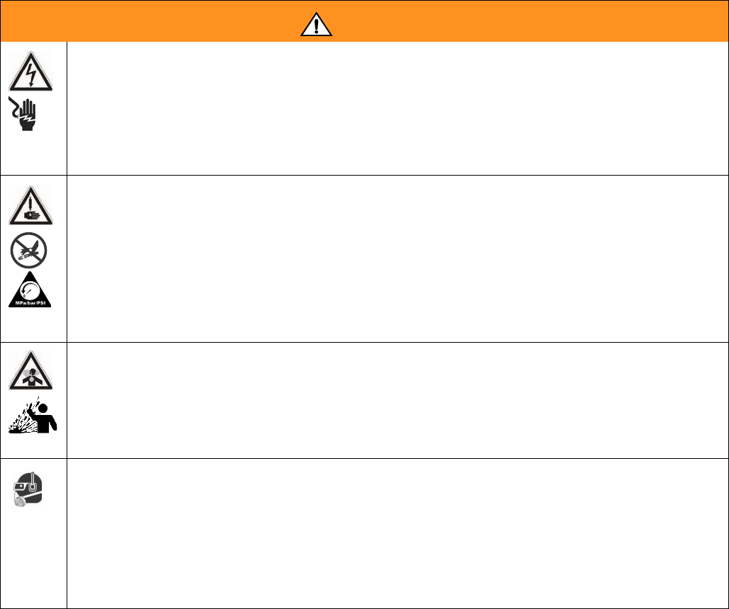
WARNING
ELECTRIC SHOCK HAZARD
Improper grounding, setup, or usage of the system can cause electric shock.
• Turn off and disconnect power cord before servicing equipment.
• Use only grounded electrical outlets.
• Use only 3-wire extension cords.
• Ensure ground prongs are intact on power and extension cords.
• Do not expose to rain. Store indoors.
SKIN INJECTION HAZARD
High-pressure fluid from dispense valve, hose leaks, or ruptured components will pierce skin. This may
look like just a cut, but it is a serious injury that can result in amputation. Get immediate surgical
treatment.
• Do not point dispense valve at anyone or at any part of the body.
• Do not put your hand over the end of the dispense nozzle.
• Do not stop or deflect leaks with your hand, body, glove, or rag.
• Follow Pressure Relief Procedure in this manual, when you stop spraying and before cleaning,
checking, or servicing equipment.
TOXIC FLUID OR FUMES HAZARD
Toxic fluids or fumes can cause serious injury or death if splashed in the eyes or on skin, inhaled, or
swallowed.
• Read MSDS’s to know the specific hazards of the fluids you are using.
• Store hazardous fluid in approved containers, and dispose of it according to applicable guidelines.
• Always wear impervious gloves when spraying or cleaning equipment.
PERSONAL PROTECTIVE EQUIPMENT
You must wear appropriate protective equipment when operating, servicing, or when in the operating
area of the equipment to help protect you from serious injury, including eye injury, inhalation of toxic
fumes, burns, and hearing loss. This equipment includes but is not limited to:
• Protective eyewear
• Clothing and respirator as recommended by the fluid and solvent manufacturer
•Gloves
• Hearing protection
Warnings
12 312760S
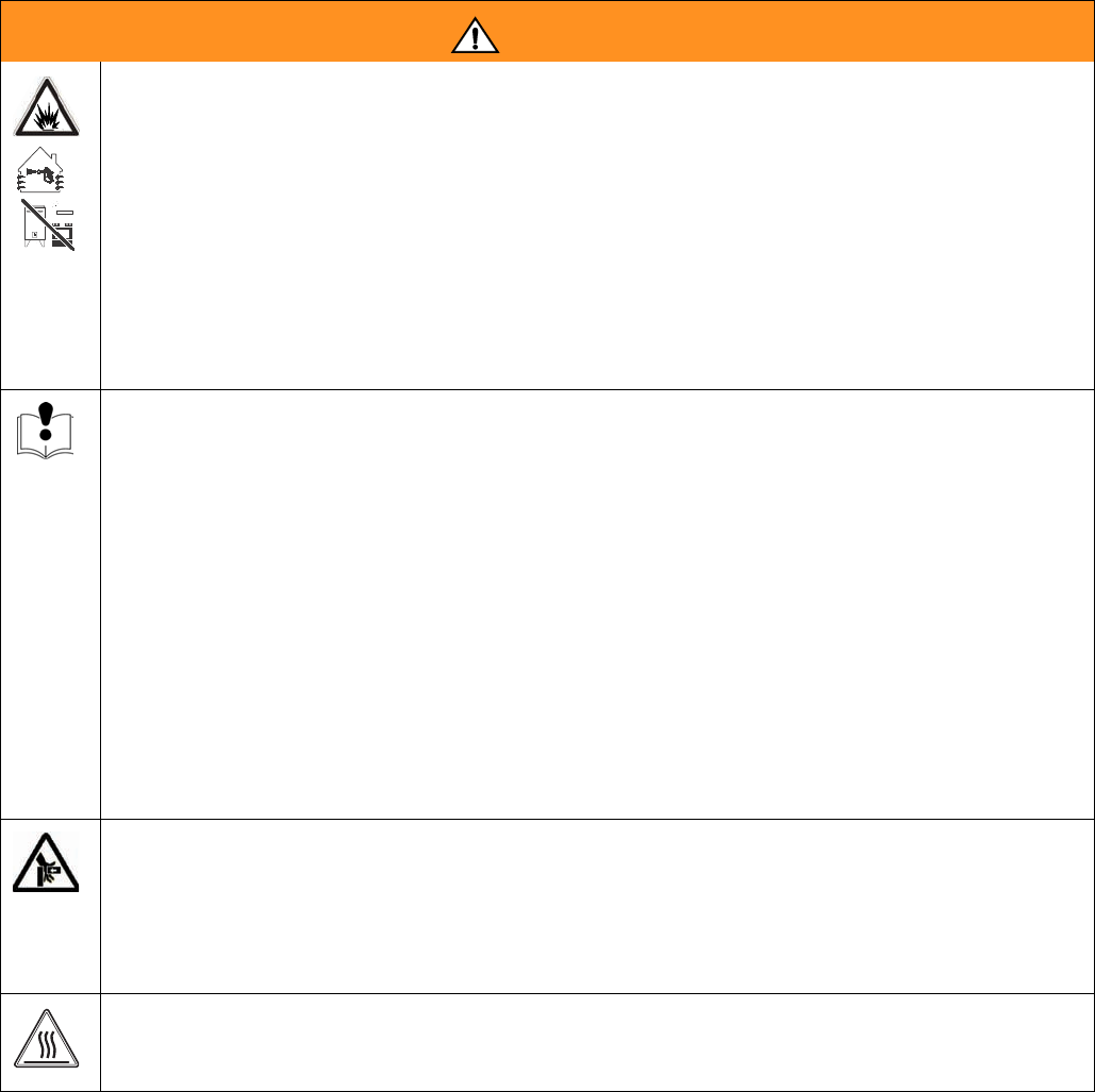
FIRE AND EXPLOSION HAZARD
Flammable fumes, such as solvent and paint fumes, in work area can ignite or explode. To help prevent
fire and explosion:
• Use equipment only in well ventilated area.
• Eliminate all ignition sources; such as pilot lights, cigarettes, portable electric lamps, and plastic
drop cloths (potential static arc).
• Keep work area free of debris, including solvent, rags and gasoline.
• Do not plug or unplug power cords or turn lights on or off when flammable fumes are present.
• Ground all equipment in the work area. See Grounding instructions.
• If there is static sparking or you feel a shock, stop operation immediately. Do not use equipment
until you identify and correct the problem.
• Keep a working fire extinguisher in the work area.
EQUIPMENT MISUSE HAZARD
Misuse can cause death or serious injury.
• Do not operate the unit when fatigued or under the influence of drugs or alcohol.
• Do not exceed the maximum working pressure or temperature rating of the lowest rated system
component. See Technical Data in all equipment manuals.
• Use fluids and solvents that are compatible with equipment wetted parts. See Technical Data in all
equipment manuals. Read fluid and solvent manufacturer’s warnings. For complete information
about your material, request MSDS forms from distributor or retailer.
• Check equipment daily. Repair or replace worn or damaged parts immediately with genuine manu-
facturer’s replacement parts only.
• Do not alter or modify equipment.
• Use equipment only for its intended purpose. Call your distributor for information.
• Route hoses and cables away from traffic areas, sharp edges, moving parts, and hot surfaces.
• Do not kink or over bend hoses or use hoses to pull equipment.
• Keep children and animals away from work area.
• Comply with all applicable safety regulations.
MOVING PARTS HAZARD
Moving parts can pinch or amputate fingers and other body parts.
• Keep clear of moving parts.
• Do not operate equipment with protective guards or covers removed.
• Pressurized equipment can start without warning. Before checking, moving, or servicing equipment,
follow the Pressure Relief Procedure in this manual. Disconnect power or air supply.
BURN HAZARD
Equipment surfaces and fluid that’s heated can become very hot during operation. To avoid severe
burns, do not touch hot fluid or equipment. Wait until equipment/fluid has cooled completely.
WARNING

Warnings
312760S 13
Grounding
14 312760S
Grounding
This product must be grounded. In the event of an elec-
trical short circuit, grounding reduces the risk of electric
shock by providing an escape wire for the electric cur-
rent. This product is equipped with a cord having a
grounding wire with an appropriate grounding plug. The
plug must be plugged into an outlet that is properly
installed and grounded in accordance with all local
codes and ordinances.
Improper installation of the grounding plug is able to
result in a risk of electric shock. When repair or replace-
ment of the cord or plug is required, do not connect the
grounding wire to either flat blade terminal. The wire
with insulation having an outer surface that is green with
or without yellow stripes is the grounding wire. Do not
modify the plug provided; if it does not fit the outlet, have
the proper outlet installed by a qualified electrician. Only
connect the product to an outlet having the same config-
uration as the plug. Do not use an adapter with this
product.
Pressure Relief
Procedure
Models with Advanced Display
Module
1. Place a waste container below the dispense valve.
2. Navigate to the Manual screen.
3. Press the Open Dispense Valve button on the Man-
ual screen to relieve chemical pressure.
4. Press the Machine Disable Mode button ( ).
5. Press the system air pressure relief switch down to
stop air supply and to vent air pressure in the
machine. It is the yellow tab at the left, rear of the
machine. The hole in the tab should be visible.
6. If necessary, run a lock through the hole to lock the
tab in place. This prevents the system air pressure
from being inadvertently enabled.
Models with Standard Display
Module
With the machine in an idle state:
1. If the machine pistons are not fully retracted, retract
the pistons by pressing in the M1 screen. See
manual 3A0429 for more information.
2. Manually open the dispense valve by pressing the
third M1 soft key until the “ ” ICON is shown in the
Current DV field. See manual 3A0429 for more infor-
mation.
3. Press the system air pressure relief switch down to
stop air supply and to vent air pressure in the
machine. It is the yellow tab at the left, rear of the
machine. The hole in the tab should be visible.
4. If necessary, run a lock through the hole to lock the
tab in place. This prevents the system air pressure
from being inadvertently enabled.
Shutdown
If the machine is to remain idle for an extended period of
time, perform the following steps.
1. Place a waste container below the dispense valve.
2. If installed, remove static mixer from the end of the
dispense valve.
Troubleshooting
16 312760S
Troubleshooting
Before starting any troubleshooting procedures, perform
the following procedure.
1. Relieve pressure. See Pressure Relief Procedure,
page 14.
2. Disconnect AC power from the machine.
3. Allow the machine to cool if the machine has a heat
control option.
Try the recommended solutions in the order given for
each problem to avoid unnecessary repairs. Verify all
circuit breakers, switches, and controls are properly set
and wiring is correct.
Problem Cause Solution
Display Module completely dark No power Verify rear AC Power switch is ON.
Fuse blown Replace machine fuses.
Loose connection Tighten 5-pin cable on Display Mod-
ule.
Bad display module Replace Display Module.
No or incorrect amount of material
dispensed from either side.
Ball valve closed (if installed) Open tank ball valve.
Tank empty Fill tank with material.
Tank clogged Verify no obstruction in the tank.
Air in material Prime the machine until the air is
removed.
Check valve malfunction Remove; clean or replace check
valve.
Piston worn or broken Remove and replace piston if worn.
Piston stalled Input air reduced or removed Reconnect input air line to machine.
Increase air pressure regulator
adjustment.
Mixer blocked Replace static mixer.
Incorporate purge timer or decrease
purge timer delay to prevent mixer
blockage.
Open Dispense Valve (ODV) adjust-
ment too late
Readjust the ODV setting to occur
sooner.
Blocked check valve Remove check valve; clean and
replace.
Air cylinder failure Remove air cylinder and reinstall air
cylinder parts as necessary.
Significant material leaking from
pump rear seal
Pump shaft worn Remove pump shaft assembly, and
reinstall rear pump rebuilt kit.

Troubleshooting
312760S 17
Material dispensed not correct weight Specific gravity of one or more of the
two materials has changed since cali-
bration
Recalibrate machine.
Machine air pressure has changed
since calibration.
Readjust air pressure regulator to
value used when machine was cali-
brated, or recalibrate machine.
Not enough material in one or more
tanks
Check tank levels; fill and prime as
necessary.
Mixer has slight obstruction Replace static mixer. Prime machine.
Check valve malfunction Remove check valve; clean or
replace as necessary.
Piston worn or broken Replace piston.
Machine dispensing off ratio One tank is empty Check tank levels. Add material if
necessary.
Tank ball valve closed Open tank ball valve. Prime machine.
Machine out of phase Rephase machine.
Check valve malfunction Remove check valve; clean or
replace as necessary.
Piston worn or broken Replace piston.
Pumps drawing material back from
valve hose
Check valve stuck open Remove check valve, clean or
replace as necessary.
Problem Cause Solution

Troubleshooting
18 312760S
Error Codes
(Advanced Display Module)
Code-Class-Event
Shown on Errors Screen Description
System
Behavior Ref
050X-A-Improper System Cal Improper Calibration 5
06CX-A-Invalid Key Token No or Invalid Key Token 4
A401-A-Over Current Z1 Heater Over Current, Zone #1 7
A402-A-Over Current Z2 Heater Over Current, Zone #2 7
A403-A-Over Current Z3 Heater Over Current, Zone #3 7
A404-A-Over Current Z4 Heater Over Current, Zone #4 7
A4C1-A-Fan Over Current Z1 High Relay 2 Current, Zone #1 7
A4C2-A-Fan Over Current Z2 High Relay 2 Current, Zone #2 7
A4C3-A-Fan Over Current Z3 High Relay 2 Current, Zone #3 7
A4C4-A-Fan Over Current Z4 High Relay 2 Current, Zone #4 7
A701-A-Heater Fault Z1 Unexpected Heater Current, Zone #1 7
A702-A-Heater Fault Z2 Unexpected Heater Current, Zone #2 7
A703-A-Heater Fault Z3 Unexpected Heater Current, Zone #3 7
A704-A-Heater Fault Z4 Unexpected Heater Current, Zone #4 7
A7C1-A-Fan Output Fault Z1 Unexpected Relay 2 Current, Zone #1 7
A7C2-A-Fan Output Fault Z2 Unexpected Relay 2 Current, Zone #2 7
A7C3-A-Fan Output Fault Z3 Unexpected Relay 2 Current, Zone #3 7
A7C4-A-Fan Output Fault Z4 Unexpected Relay 2 Current, Zone #4 7
B10X-A-Small Shot Request Less Than Minimum Shot Requested 5
CAC1-A-Comm. Error FCM 1 Communication Error, FCM3 #1 2
CAC1-A-Comm. Error FCM2 Communication Error, FCM3 #2 3
CAC1-A-Comm. Error Heat Z1 Communication Error, Heat Zone #1 1
CAC1-A-Comm. Error Heat Z2 Communication Error, Heat Zone #2 1
CAC1-A-Comm. Error Heat Z3 Communication Error, Heat Zone #3 1
CAC1-A-Comm. Error Heat Z4 Communication Error, Heat Zone #4 1
DEFX-A-Piston Timeout Piston Stroke Timeout 5
DJ0X-D-Linear Sensor Fault Bad Linear Position Sensor 6
F2A-Low Flow A Side Low A Side Fluid Flow, relative to calibra-
tion and user-input allowable variance.
6

Troubleshooting
312760S 19
F2B-Low Flow B Side Low B Side Fluid Flow, relative to calibra-
tion and user-input allowable variance.
6
F2FX-D-Delta Velocity Minus Delta Velocity Minus 6
F3FX-D-Delta Velocity Plus Delta Velocity Plus 6
F6A-Flow Meter A Problem Flow Meter A Problem, or bad connection
between Fluid Control Module and Flow
Meter A
6
F6B-Flow Meter B Problem Flow Meter B Problem, or bad connection
between Fluid Control Module and Flow
Meter B
6
L2AX-D-Low Level Tank A Low Material Level, Tank A 6
L2BX-D-Low Level Tank B Low Material Level, Tank B 6
L2FX-D-Low Level Tank A/B Low Material Level, Both Tanks 6
L8AX-D-Refill Timeout A Auto Refill Failed, A Side 6
L8AX-D-Refill Timeout B Auto Refill Failed, B Side 6
P2AX-D-Low Pressure A A Side Low Pressure, relative to calibra-
tion and user-input allowable variance.
6
P2BX-D-Low Pressure B B Side Low Pressure, relative to calibra-
tion and user-input allowable variance.
6
P3AX-D-High Pressure A A Side High Pressure, relative to calibra-
tion and user-input allowable variance.
6
P3BX-D-High Pressure B B Side High Pressure, relative to calibra-
tion and user-input allowable variance.
6
P6AX-D-Pressure Fault A Problem with A Side Piston Pressure
Transducer or Transducer Connection
6
P6BX-D-Pressure Fault B Problem with B Side Piston Pressure
Transducer or Transducer Connection
6
P6DX-D-Pressure Fault A/B Problem with A and B Side Piston Pres-
sure Transducer or Transducer Connec-
tion
6
P7DX-D-Out of Phase Machine Out of Phase, relative to calibra-
tion and user-input allowable variance.
6
R2-A:B Ratio Low A:B Ratio is low, relative to calibration and
user-input allowable variance.
6
R3-A:B Ratio High A:B Ratio is high, relative to calibration
and user-input allowable variance.
6
T201-D-Low Material Temp Z1 Material Below Temperature, Zone #1 8
T202-D-Low Material Temp Z2 Material Below Temperature, Zone #2 8
Code-Class-Event
Shown on Errors Screen Description
System
Behavior Ref

Troubleshooting
20 312760S
T203-D-Low Material Temp Z3 Material Below Temperature, Zone #3 8
T204-D-Low Material Temp Z4 Material Below Temperature, Zone #4 8
T401-A-High Material Temp Z1 Material Over Temperature, Zone #1 7
T402-A-High Material Temp Z2 Material Over Temperature, Zone #2 7
T403-A-High Material Temp Z3 Material Over Temperature, Zone #3 7
T404-A-High Material Temp Z4 Material Over Temperature, Zone #4 7
T4C1-A-Blanket Over Temp Z1 Blanket Over Temperature, Zone #1 7
T4C2-A-Blanket Over Temp Z2 Blanket Over Temperature, Zone #2 7
T4C3-A-Blanket Over Temp Z3 Blanket Over Temperature, Zone #3 7
T4C4-A-Blanket Over Temp Z4 Blanket Over Temperature, Zone #4 7
T601-A-Material RTD Fault Z1 Material RTD Fault, Zone #1 7
T602-A-Material RTD Fault Z2 Material RTD Fault, Zone #2 7
T603-A-Material RTD Fault Z3 Material RTD Fault, Zone #3 7
T604-A-Material RTD Fault Z4 Material RTD Fault, Zone #4 7
T6C1-A-Blanket RTD Fault Z1 Blanket RTD Fault, Zone #1 7
T6C2-A-Blanket RTD Fault Z2 Blanket RTD Fault, Zone #2 7
T6C3-A-Blanket RTD Fault Z3 Blanket RTD Fault, Zone #3 7
T6C4-A-Blanket RTD Fault Z4 Blanket RTD Fault, Zone #4 7
T801-A-No Heat Z1 No Temperature Rise, Zone #1 7
T802-A-No Heat Z2 No Temperature Rise, Zone #2 7
T803-A-No Heat Z3 No Temperature Rise, Zone #3 7
T804-A-No Heat Z4 No Temperature Rise, Zone #4 7
T901-A-Temp Switch Cutoff Z1 Over Temp Switch Open, Zone #1 7
T902-A-Temp Switch Cutoff Z2 Over Temp Switch Open, Zone #2 7
T903-A-Temp Switch Cutoff Z3 Over Temp Switch Open, Zone #3 7
T904-A-Temp Switch Cutoff Z4 Over Temp Switch Open, Zone #4 7
T9C1-A-Control Shutdown Z1 PCB Over Temperature, Zone #1 7
T9C2-A-Control Shutdown Z2 PCB Over Temperature, Zone #2 7
T9C3-A-Control Shutdown Z3 PCB Over Temperature, Zone #3 7
T9C4-A-Control Shutdown Z4 PCB Over Temperature, Zone #4 7
WM01-A-Current Fault Z1 High Relay 1 Current, Zone #1 7
Code-Class-Event
Shown on Errors Screen Description
System
Behavior Ref
Troubleshooting
312760S 21
System Behavior Descriptions
NOTE: System behavior descriptions apply only to
Advanced Display Module errors.
WM02-A-Current Fault Z2 High Relay 1 Current, Zone #2 7
WM03-A-Current Fault Z3 High Relay 1 Current, Zone #3 7
WM04-A-Current Fault Z4 High Relay 1 Current, Zone #4 7
WMC1-A-Control Fault Z1 Unexpected Relay 1 Current, Zone #1 7
WMC2-A-Control Fault Z2 Unexpected Relay 1 Current, Zone #2 7
WMC3-A-Control Fault Z3 Unexpected Relay 1 Current, Zone #3 7
WMC4-A-Control Fault Z4 Unexpected Relay 1 Current, Zone #4 7
Code-Class-Event
Shown on Errors Screen Description
System
Behavior Ref
System
Behavior
Reference System Behavior Description
1
When this error is generated, a pop-up with the error-code will be shown until it is acknowledged by
pressing the Enter button ( ). The heat control will be turned off, any auto-sequencing in progress
will be stopped, and the foot switch will be disabled until the error-code is acknowledged. When the
error condition is cleared, the heat control may be turned back on from the Home screen. This error
will not disable purge or recirculation operation.
2
When this error is generated, a pop-up with the error-code will be shown until it is acknowledged by
pressing the Enter button ( ). All physical machine operation will be disabled until the error condi-
tion is corrected. The display module can still be used but all machine commands sent will be ignored.
3
When this error is generated, a pop-up with the error-code will be shown until it is acknowledged by
pressing the Enter button ( ). Any auto-sequencing in progress will be stopped and the foot
switch will be disabled until the error-code is acknowledged. This error will not disable purge or recir-
culation operation. All features dependent on Fluid Control Module #2 will be disabled until the error
condition is corrected.
4
When this error is generated, a pop-up with the error-code will be shown continuously until the error
condition is corrected. The machine and display module are completely disabled until the error condi-
tion is corrected.
5
When this error is generated, a pop-up with the error-code will be shown. Any auto-sequencing, purge
timer or recirculation timer operation in progress will be stopped and the foot switch will be disabled
until the error-condition is cleared. The error-code pop-up will be shown until the error condition is
cleared. When the error condition is cleared, all options may be turned back on.

Troubleshooting
22 312760S
6
When this error is generated, a pop-up with the error-code will be shown until it is acknowledged by
pressing the Enter button ( ). Any auto-sequencing in progress will be stopped, and the foot
switch will be disabled until the error-code is acknowledged. Once the error-code pop-up is acknowl-
edged, the machine will return to normal operation The error will be shown in the Errors screen until
the condition is cleared. The error-code pop-up will not reappear unless the error condition is cleared
and then reappears. This error will not disable purge or recirculation operation.
7
When this error is generated, a pop-up with the error-code will be shown until it is acknowledged by
pressing the Enter button ( ). All heat options will be turned off, any auto-sequencing in progress
will be stopped, and the foot switch will be disabled until the error-code is acknowledged. When the
error condition is cleared, the heat control may be turned back on from the Home screen. This error
will not disable purge or recirculation operation.
8
When this error is generated, a pop-up with the error-code will be shown until it is acknowledged by
pressing the Enter button ( ). All heat options will remain on, any auto-sequencing in progress
will be stopped, and the foot switch will be disabled until the error-code is acknowledged. This error
will not disable purge or recirculation operation.
System
Behavior
Reference System Behavior Description
Troubleshooting
312760S 23
Error Codes
(Standard Display Module)
When the machine is operating and a fault is detected, it
will report the condition by generating an error code.
Error codes are typically generated when the machine is
idle after dispensing a shot.
When error codes are generated, a screen will be dis-
played which contains an animation sequence, the error
code number and an ICON symbol representing the
condition detected. The HMI will also output an error
code tone sequence. The tone sequence cannot be dis-
abled.
When errors are generated, the machine will automati-
cally be disabled and remain in an idle state until the
user acknowledges the condition. Any active purge timer
present prior to error code generation will be sus-
pended, and will need re-started by requesting a shot
after the error is acknowledged.
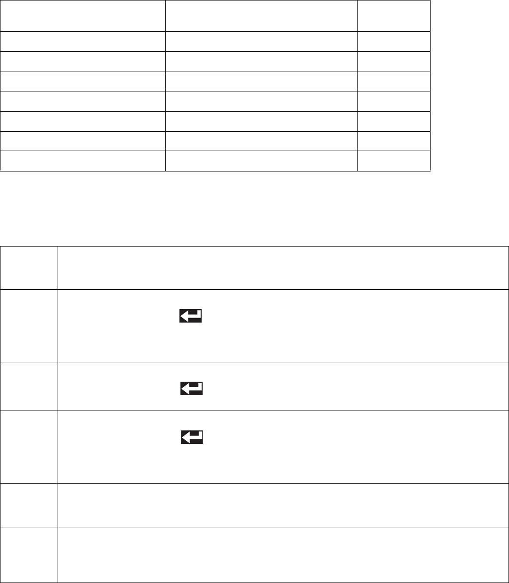
The following typical screen is generated when an error
code is generated:
Key:
A Error Code Animation Field
B Error Code Number Field
D Error Code ICON
E Error Code Acknowledgement ICON
When an error code is generated, the user will need to
acknowledge the condition by pressing the soft key
under the ICON.
After the user activates the key, the error number
shown in FIG. 1, will be displayed on the bottom left
hand corner of the Run screen, while the condition is still
present.
The example E12 number on the main run screen will
remain on the run screen as long as the error condition
exists. If the problem is corrected the example E12 num-
ber will be removed.
If more than 1 error code condition exists for the
machine, the corresponding “EXX” numbers will be
listed on the bottom left corner, separated by commas.
FIG. 1: Typical Error Code Screen
FIG. 2: Typical Run Screen with Active Error Code
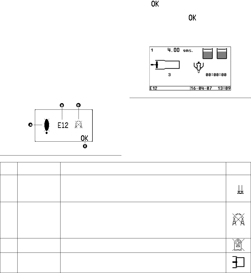
Error
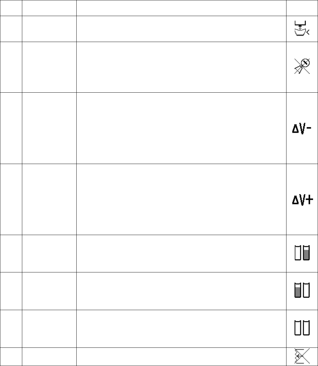
Code Title Cause, Details ICON
E11 Stuck Key Error A key on membrane has been active (pressed) for > 30 seconds
continuously. Replace the HMI. This error code does not require user
acknowledgment and will clear itself automatically if the condition is
removed.
E12 Communication
Error
The Display module has lost communication with the Fluid Control Module.
Material dispensing will be disabled if this condition exists. Check
communication cables between the 2 electronic components, or check the
HMI and/or the Fluid Control Module.
This error will be regenerated continuously while the condition exists.
E13 No or Invalid Run
Token Error
The Run Token in the FCM is missing (not installed), or does not have the
correct data.
E21 Piston Stroke
Time-out Error
A piston stroke action has taken > 55 seconds. Typically caused by no/too
little air pressure to the machine or a mechanical interference with the
piston has occurred. Check machine input line pressure.
Troubleshooting
24 312760S
E23 Less than
Minimum Shot
Requested Error
User has requested a shot < the minimum allowable size entered during
calibration. (< 15% of stoke, N/A in Operator Mode).
E24 Improper
Calibration Error
The calibration done on the machine is invalid, so the requested shot
cannot be executed. For instance, a Large Stroke Calibration Shot mass
which is less than the Short Stroke Calibration Shot mass (C4 screen) will
create this error code. If the wiring to the linear position transducer is
reversed this error will appear. If invalid piston positions are calibrated into
the machine (C1 screen) this error will appear.
E25 Delta Velocity
(“V”) Minus Error
The piston velocity is slower than the calibration velocity measured, by the
percentage amount selected by the user (20%, 40% or 60%). If the user
selects 0%, this monitoring or alarm feature is disabled.
If generated, shot size accuracy may be degraded. Typically the problem is
created when the machine pressure regulator is adjusted to different value
from when the machine was calibrated. Another less likely cause could be a
mechanical failure with dispensing (worn piston, etc.). This error will not be
generated for a purge shot or when the machine is in Operator mode.
E26 Delta Velocity
(“V”) Plus Error
The piston velocity is faster than the calibration velocity measured, by the
percentage amount selected by the user (20%, 40% or 60%). If the user
selects 0%, this monitoring or alarm feature is disabled.
If generated, shot size accuracy may be degraded. Typically the problem is
created when the machine pressure regulator is adjusted to different value
from when the machine was calibrated. Another less likely cause could be a
mechanical failure with dispensing (worn piston, etc.). This error will not be
generated for a purge shot, or when the machine is in Operator mode.
E27 Low Material
Level, Tank A
Alarm or Error
Tank A is low (only generated if tank sensing is enabled). Fill tank A with
material.
Tank level errors will be generated after every shot if the condition still
exists.
E28 Low Material
Level, Tank B
Alarm or Error
Tank B is low (only generated if tank sensing is enabled). Fill tank B with
material.
Tank level errors will be generated after every shot if the condition still
exists.
E29 Low Material
Level, Both Tanks
Alarm or Error
Both tanks are low (only generated if tank sensing is enabled). Fill both
tanks with material.
Tank level errors will be generated after every shot if the condition still
exists.
E50 Bad Linear
Position Sensor
There is a fault with the linear position sensor. Check wiring or replace.
Error
Code Title Cause, Details ICON
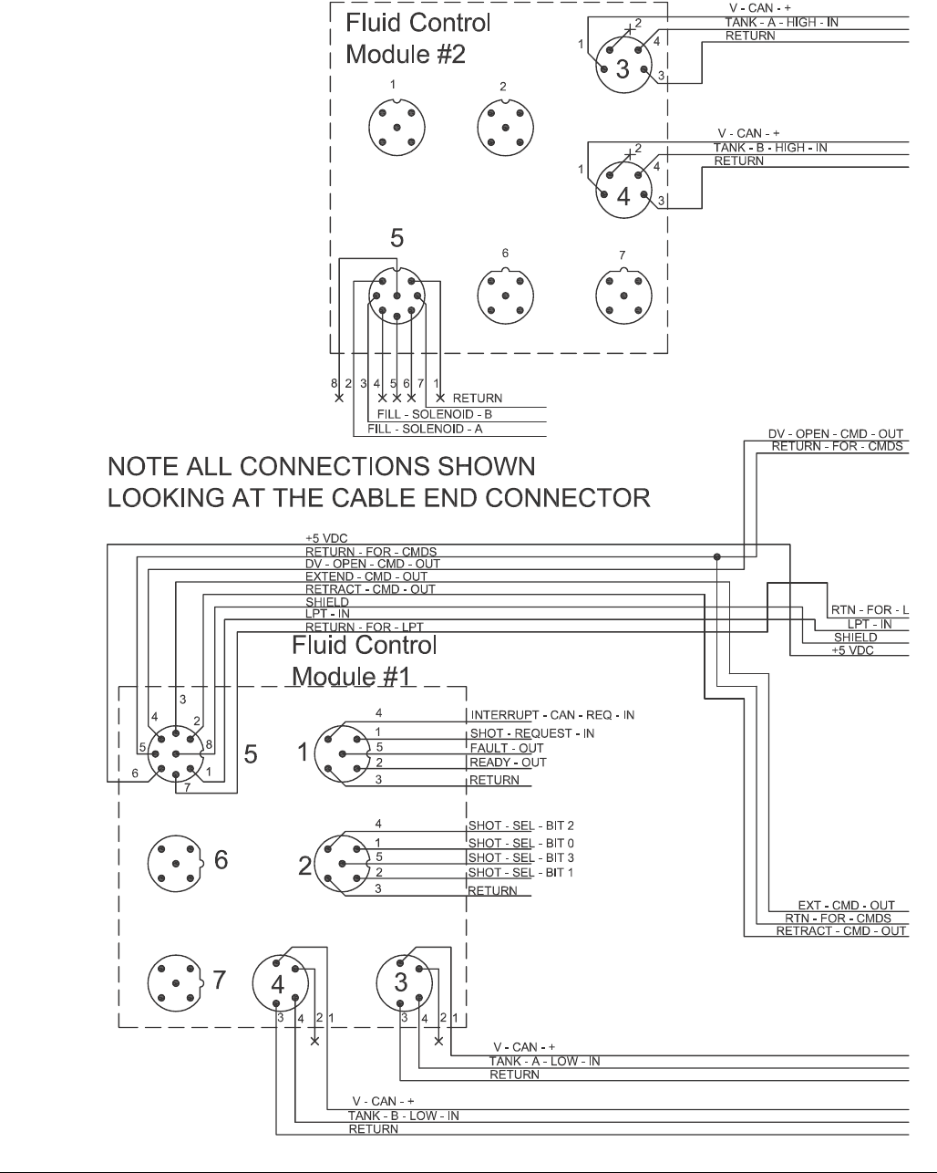
Electrical Schematics
26 312760S
FIG. 4: Electrical Schematic - Page 2
A
B
C
D
E
F
G
H
J
K
L
M
N
P
R
S
T
U
V
W
X
Electrical Schematics
28 312760S
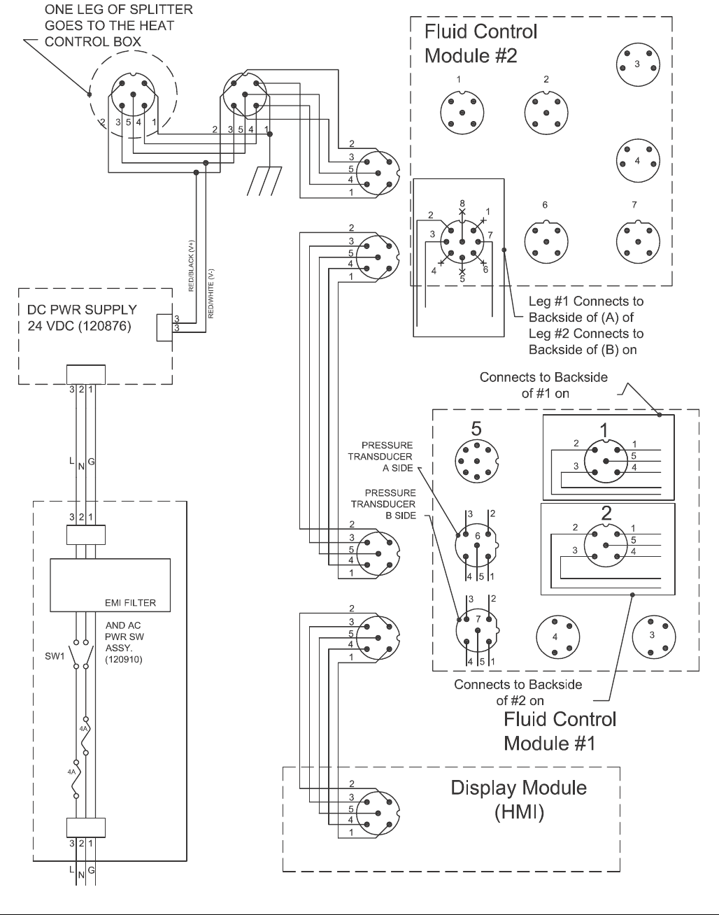
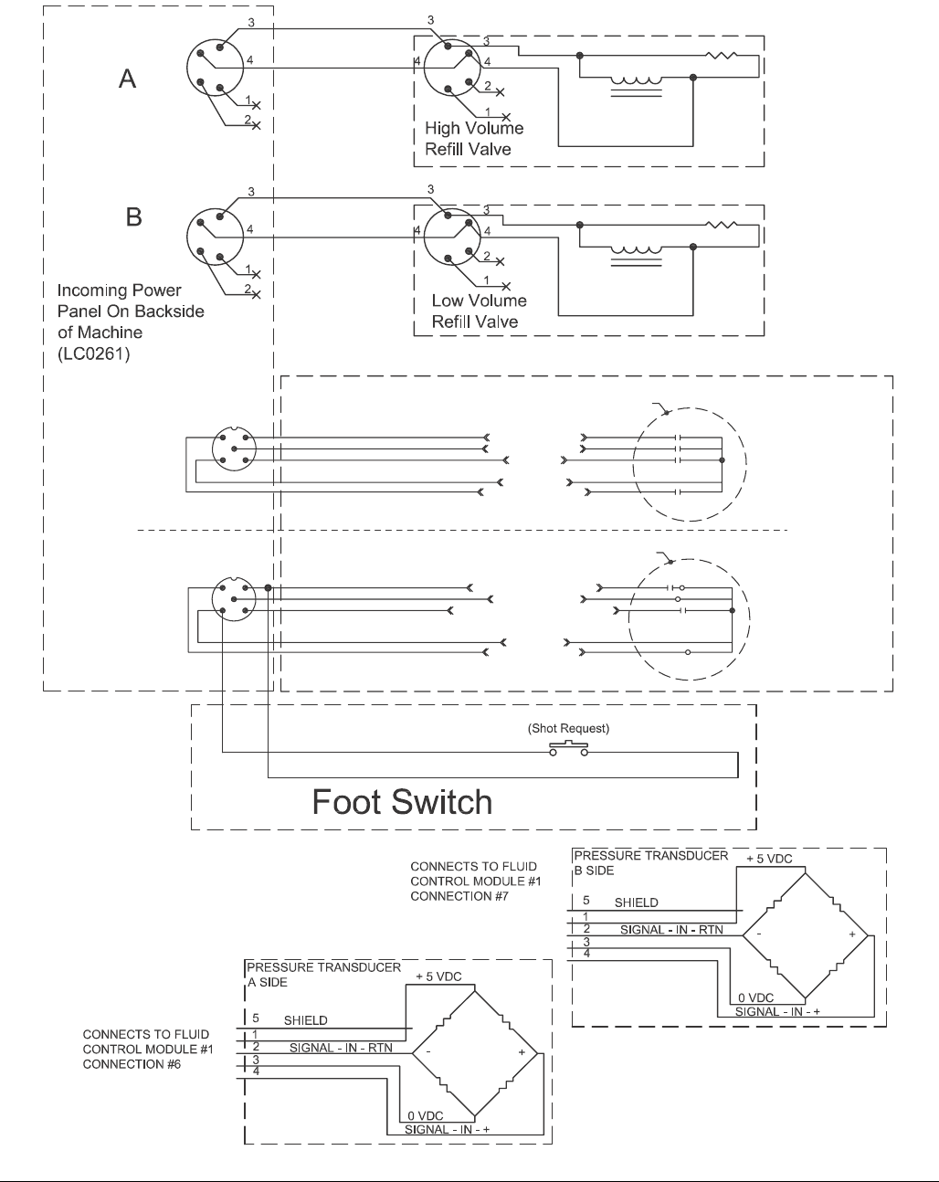
NOTE: See PR70 operation manual for Optional External Control Interface instructions.
FIG. 6: Electrical Schematic - Page 4
2
1
4
5
1
3
2
4
5
1
3
2
Customer Supplied
Dry Contact/Relay
Customer Supplied
Dry Contact/Relay
SHOT SEL - BIT 0
SHOT SEL - BIT 3
Not Used
COMMON
SHOT SEL - BIT 1
SHOT REQUEST - INPUT
FAULT OUTPUT
INTERRUPT - CAN - REQ - INPUT
COMMON
READY - OUTPUT
Brown
Gray
Black
Blue
White
Brown
+24 VDC
+24 VDC
Gray
Black
Blue
White
NOTE: Connector #1 is for use
with all systems.
NOTE: View shown is looking at
pins on end of cable.
NOTE: Connector #2 is for use
with systems with an Advanced
Display Module only.
NOTE: View shown is looking at
pins on end of cable.
Repair
312760S 29
Repair
HydraCheck Kit Installation
FIG. 7: HydraCheck Installation - Variable Ratio Base
203
200b 200a 200c
200d
Torque to 85 in-lb (9.6 N•m).
1
1
ti12437a
AA
FIG. 8: HydraCheck Installation - Fixed Ratio Base
100d
100b
420
103
104
ti12436a
Repair
30 312760S
NOTE: The HydraCheck kit is intended to be used with
low viscosity materials to minimize splashing. It is not
intended to be used as a timer or flow control device.
Prepare Machine for Kit Installation
1. Navigate to the Manual screen.
2. Press the Retract Piston Command button.
3. Relieve system pressure. See Pressure Relief Pro-
cedure on page 14.
4. Remove shroud screws (2202, 2409). See FIG. 17
on page 44 and FIG. 21 on page 49.
5. Remove the shroud (117, 214). See FIG. 16 on
page 42 and FIG. 21 on page 49.
Install HydraCheck Shock
6. Install shock absorber (200a) through the opening in
the pump sub-assembly (203) with the groove for
the snap ring on the back of the pump assembly.
The shock absorber can be inserted through the
front or the back of the pump sub-assembly.
7. Install shock snap ring (included with shock, not
shown) onto the shock absorber (200a) in the
groove farthest from the pump sub-assembly.
8. Install set screw (200b) and torque to 85 in-lb
(9.6 N•m).
Install Adjustment Screw/Cap
9. On Variable Ratio models, loosely install hex
nut (200d) and adjustment screw (200c) onto the
variable ratio drive block (AA).
On Fixed Ratio models, loosely install hex
nut (100b) and adjustment cap (100d) onto the air
cylinder shaft (420).
Adjust the Adjustment Screw/Cap
10. Push the drive block (104, AA) forward until resis-
tance is felt when it engages the cylinder. Make sure
the resistance is not due to shock absorber (200a)
contact with the adjustment screw (200c) or adjust-
ment cap (100d).
11. Adjust the adjustment screw or adjustment cap until
it contacts the shock absorber.
12. On Variable Ratio models, hold the adjustment
screw (200c) in place and tighten the hex nut (200d)
against the drive block (AA).
On Fixed Ratio models, hold the adjustment
cap (100d) in place and tighten the hex nut (100b)
against the adjustment cap.
Prepare Machine for Operation
13. Lift the system air pressure relief switch to enable
system pressure. It is the yellow tab at the left, rear
of the machine.
Adjust Shock Resistance
14. Execute a shot to see how the shock absorber
affects the speed of the drive block (104, AA).
15. The shock absorber has a numeric scale on one
side. Rotate the knob with the scale to a higher
value for more resistance. Rotate the knob to a
lower value for less resistance.
16. Repeat these steps until the desired resistance is
achieved.
The following procedure is the same for Fixed and
Variable Ratio bases, except where noted. See FIG.
7 and FIG. 8 for part references. See Kits on
page 80 for kit numbers.
Be sure that system pressure is relieved and dis-
abled before proceeding.
Repair
312760S 31
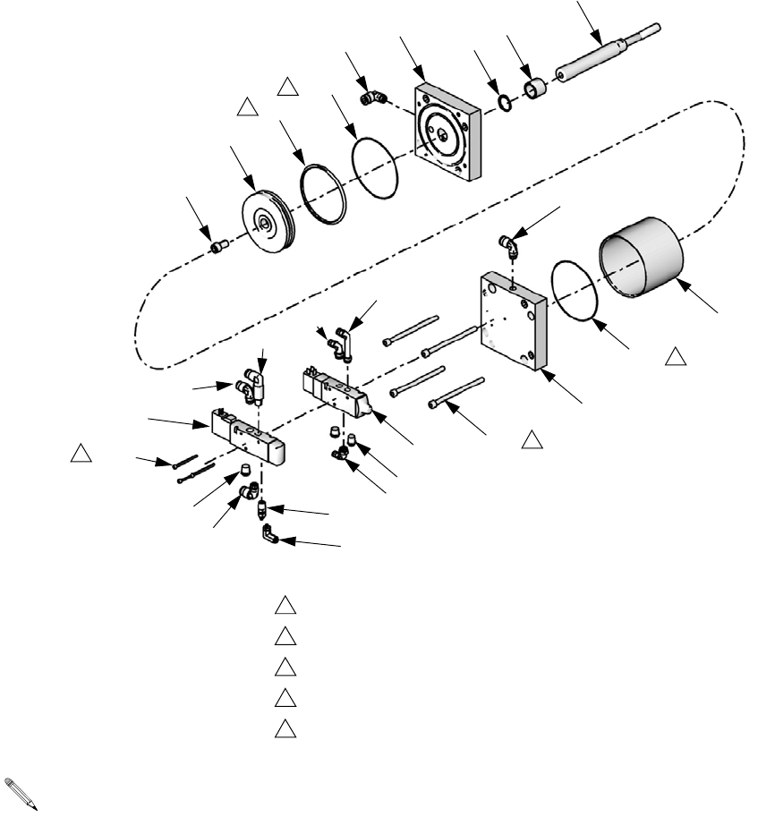
Air Cylinder Kit Installation
Prepare Machine for Kit Installation
1. Relieve pressure. See Pressure Relief Procedure,
page 14.
2. Shut down the machine. See Shutdown, page 14.
3. Disconnect the pressurized air input hose.
4. Remove shroud screws (2202, 2409). See FIG. 17
on page 44 and FIG. 21 on page 49.
5. Remove the shroud (117, 214). See FIG. 16 on
page 42 and FIG. 21 on page 49.
Disassemble the Air Cylinder
6. Remove the incoming power bracket (110) from the
machine by removing the two attachment
screws (109). See FIG. 15 on page 41.
7. Remove the two solenoid valves (407, 408) from the
cylinder blind end block (418) by removing the three
socket head cap screws (402).
8. Use an open-end wrench to remove all hex
nuts (103, 100b, 100d) connecting the piston rod to
the drive block. See FIG. 15 on page 41.
9. Remove the four screws (108) that attach the cylin-
der rod end block (417) to the frame. See FIG. 15 on
page 41. Access the screws through the four holes
416
411
418
404
414
415
409
410
412
414
402
407
412
422
415
413
412
420
405
401
417
412
411
403
419
406
408
Torque to 41 in-lb (4.6 N•m).
Torque to 350 in-lb (39.5 N•m).
Torque to 100 ft-lb (135 N•m).
Coat all sliding surfaces with lubricant, part 115982.
Apply sealant tape to npt fittings.
1
2
3
4
5
2
1
4
4
4
ti12490a
See Kits on page 80 for kit numbers.
Repair
32 312760S
in the blind end block (418) using a long allen
wrench.
10. Partially remove the air cylinder by pulling on the
cylinder from the back of the machine until the air
lines at the elbow fittings can be seen.
11. With the cylinder partially removed, disconnect the
airlines at the air cylinder elbow fittings.
12. Finish removing air cylinder.
13. On a bench, disassemble the air cylinder by remov-
ing the four long screws (404) that connect the two
cylinder blocks.
Clean and Inspect the Parts
14. Inspect the cylinder tube (416) and piston (419) for
scratches. Replace if necessary.
15. Using a clean dry cloth, remove any grease from the
inside of the tube (416), the outside of the
piston (419), and the cylinder rod (420).
16. Remove the two cylinder block o-rings (411) from
the blocks (417, 418) and replace.
17. Remove the piston o-ring (403) and replace.
18. Remove the cylinder rod (420) from the rod end
block (417).
19. Remove the rod o-ring (401) from the rod end
block (417) and replace.
20. Liberally apply high temperature lubricant grease
(part 115982) to the inside of the tube (416), the
outside of the piston (419), all the o-rings, and the
cylinder rod (420).
Re-Assemble the Air Cylinder
21. Reinstall the four long screws (404) that attach the
two drive blocks (417, 418) by finger-tightening
them. Then torque the bolts to 350 in-lb (39.5 N•m)
in a crisscross pattern.
22. Insert the cylinder rod (420) through the hole in the
rod end cylinder block (417) and base frame.
23. Before the cylinder is completely in place, reconnect
the airlines to the cylinder block elbows fittings. Ver-
ify the correct airlines are connected.
24. Reinstall the four screws (108) that attach the cylin-
der rod end block (417) to the frame. See FIG. 15 on
page 41.
25. Reinstall the hex nuts (103, 100b, 100d) to the cylin-
der rod (420) and torque to 100 ft-lb (135 N•m). See
FIG. 15 on page 41.
26. Install the three screws (402) that attach the sole-
noid valves (407, 408) to the blind end block (418).
Torque to 41 in-lb (4.6 N•m).
Prepare Machine for Operation
27. Reattach the incoming power bracket (110) by rein-
stalling the two attachment screws (109). See FIG.
15 on page 41.
28. Reconnect pressurized air input hose.
29. Operate the machine and ensure there are no air
leaks are found.
30. Install the shroud (117, 214). See FIG. 20 on page
47 and FIG. 21 on page 49.
31. Install shroud screws (2202, 2409). See FIG. 17 on
page 44 and FIG. 21 on page 49.
32. Calibrate the machine. See the appropriate opera-
tion manual referenced at the beginning of this man-
ual for procedure.
NOTICE
In the following step, the long screws must be tight-
ened in a crisscross pattern. Failure to do so may
result in air cylinder damage.
1
2
3
4
Repair
312760S 33
Rear Pump Rebuild Kit Installation
Prepare Machine for Kit Installation
1. Drain the pump.
•If ball valves are installed, close the ball
valves then take several shots.
•If ball valves are not installed, empty the
tanks. Perform shots repeatedly until no mate-
rial comes out of the dispense valve.
2. Relieve pressure. See Pressure Relief Procedure,
page 14.
3. Shut down the machine. See Shutdown, page 14.
4. Disconnect the pressurized air input hose.
5. Remove shroud screws (2202, 2409). See FIG. 17
on page 44 and FIG. 21 on page 49.
The pump shaft is installed with Krytox. Contact with
Krytox can lead to flu-like symptoms. The MSDS for
this material is available upon request.
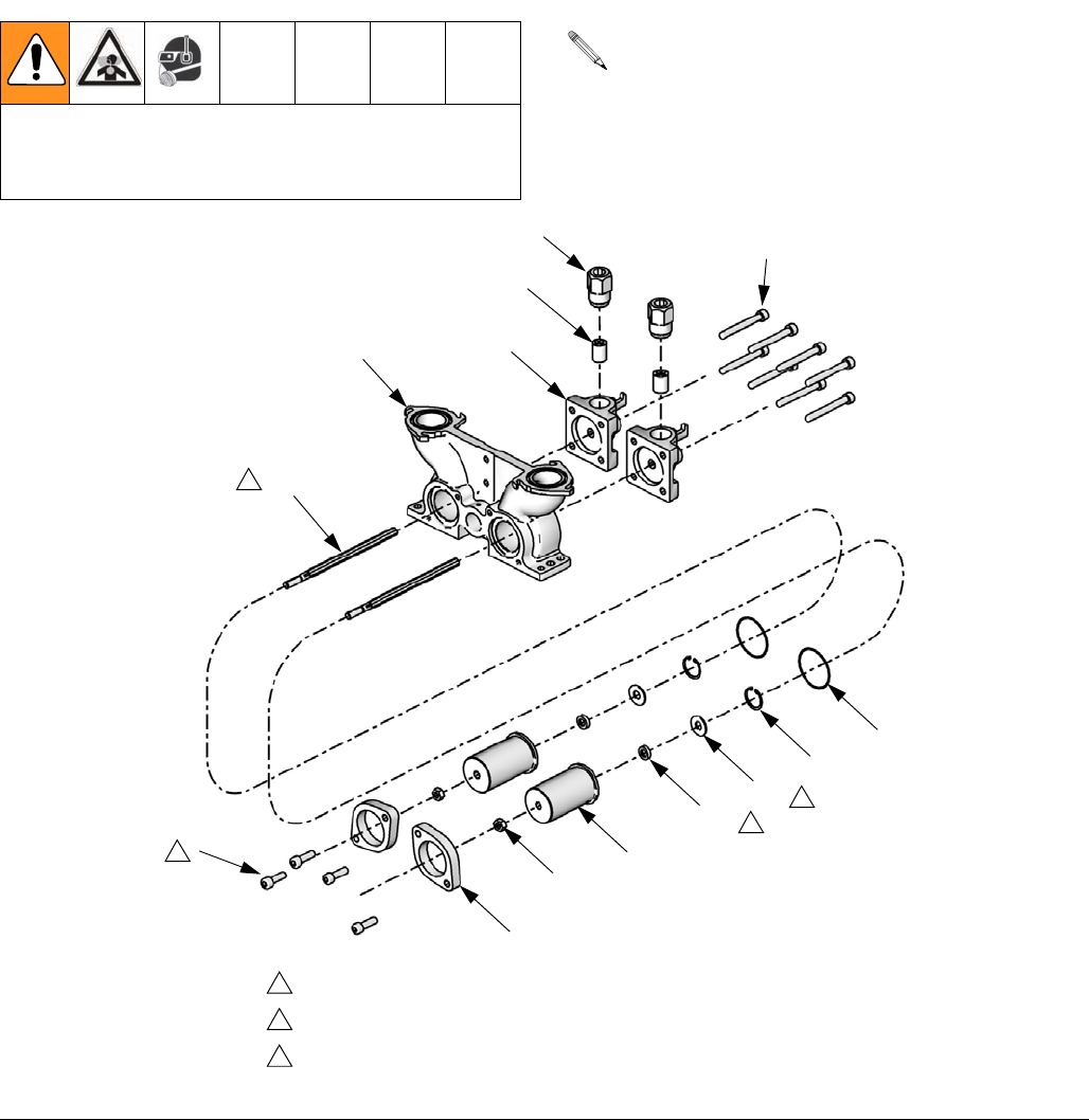
See Kits on page 80 for kit numbers.
FIG. 9
506
513
514
508
507
511
501
504
512
503
510
502
509
505
Torque to 350 in-lb (39.5 N•m).
Lube shaft with krytox grease prior to insertion into bearing.
Shaft seal (503) must be installed with open side facing the washer (512).
1
2
3
2
1
3
ti12491a
3

Repair
34 312760S
6. Remove the shroud (117, 214). See FIG. 16 on
page 42 and FIG. 21 on page 49.
Disassemble the Rear Pump Assembly
7. Disconnect the pump shaft (511) from the drive
block.
a. Loosen the shaft locking nut (502).
b. Hold the drive block alignment rod (2302, 2419)
stationary with a wrench. See FIG. 18 on page
45 and FIG. 22 on page 50.
c. Turn the pump shaft (511) with a wrench.
d. Manually push the pump shaft (511) forward to
to separate the shaft from the drive block.
8. Remove the shaft lock nut (502).
9. Remove the two screws (505) that hold the pump
collar in place.
10. Remove the pump collar (509) from the pump
housing (507).
11. Slide the pump bearing housing (510) away from
the pump housing (507) to remove.
12. Remove rear pump components from the pump
bearing housing (510).
Clean and Inspect the Parts
13. Using a clean dry cloth, remove any existing grease
from the bearing housing.
14. Apply new high temperature grease lubricant
(part 115982) to the inside of the pump bearing
housing (510), and the new rebuild components.
Assemble the Rear Pump Assembly
15. Install the new rebuild kit components into the bear-
ing housing.
16. Apply one layer of thin masking tape over the male
threads of the pump shaft that mates with the drive
block. This will prevent the threads from damaging
the seal (503).
17. Slide the pump shaft through the hole in the bearing
housing.
18. Align the bearing housing in position next to the
pump housing.
19. Install the pump collar over the bearing housing.
20. Attach the pump housing using the two
screws (505) and torque to 350 in-lb (39.5 N•m).
21. Remove the masking tape from pump shaft (511).
22. Install the pump shaft lock nut (502) onto the pump
shaft (511).
23. Connect the pump shaft to the drive block alignment
rod (2302, 2419). See FIG. 18 on page 45 and FIG.
22 on page 50. Screw the shaft completely into the
drive block.
24. Tighten the lock nut (502)
Prepare for Operation
25. Open the tank ball valves if installed.
26. Fill tanks.
27. Perform several shots to fill the pump with new
material.
28. Calibrate and phase the machine. See the appropri-
ate operation manual referenced at the beginning of
this manual for procedure.
NOTICE
Be careful when installing the seal (503). Ensure
there is masking tape on the threads of the piston rod
and that the open side of the seal faces the piston rod
when it slides onto the rod.
Repair
312760S 35
Piston/Cylinder Replacement Kit
Installation
Prepare Machine for Kit Installation
1. Drain the pump.
•If ball valves are installed, close the ball
valves then take several shots.
•If ball valves are not installed, empty the
tanks. Perform shots repeatedly until no mate-
rial comes out of the dispense valve.
2. Relieve pressure. See Pressure Relief Procedure,
page 14.
3. Models with ADM: To prevent machine movement,
press the Machine Disable Mode key ( ).
Models with SDM: To prevent machine movement,
press the Red button .
Disassemble Cylinder
4. Remove the four end cap screws (506). See FIG. 9
on page 33.
5. Remove the pump end caps (508). See FIG. 9 on
page 33. Allow the cap to hang by the hose.
6. Remove the cylinder (601) and o-rings (606) from
the pump housing (507). See FIG. 9 on page 33.
7. Push the drive block (104, AA) forward until pistons
are fully extended. See FIG. 7 and FIG. 8 on
page 29.
8. Use a wrench to prevent the pump shaft (511) from
rotating and remove the piston screw (605). See
FIG. 9 on page 33.
9. Remove the piston (602) and any front or rear
washers (603) from the pump shaft (511). See FIG.
9 on page 33.
10. Clean the washers.
Install Cylinder
11. Install the new piston and any front or rear washers.
12. Install the piston screw (605).
13. Fully retract the piston.
14. Lubricate the new o-rings with high temperature
grease (part 115982).
15. Insert the lubricated o-rings (606) into the grooves
of the pump housing (507) and end caps (508). See
FIG. 9 on page 33.
16. Install the cylinder between the pump housing (507)
and end cap (508). See FIG. 9 on page 33.
17. Secure cylinder in place with the four end cap
screws (506). See FIG. 9 on page 33.
Prepare Machine for Operation
18. Open the tank ball valves if installed.
19. Fill tanks.
20. Perform several shots to fill the pump housing (507)
with new material.
21. Calibrate and phase the machine. See the operation
manual referenced at the beginning of this manual
for procedure.
See Piston Package on page 60 and Nylon and
UHMW Piston Replacement Kits on page 63 for
kit numbers.
606
601
606
605
603
602
604
ti12438a
1
The arrow imprinted on the cylinder points
toward the pump outlet.
1
Tighten the piston screw until the piston stops rotat-
ing, then turn the screw an additional 1/4 turn.
Repair
36 312760S
Check Valve Rebuild Kit
Installation
Prepare Machine for Kit Installation
1. Relieve pressure. See Pressure Relief Procedure,
page 14.
2. Models with ADM: To prevent machine movement,
press the Machine Disable Mode key ( ).
Models with SDM: To prevent machine movement,
press the Red button .
3. Place a waste container below the dispense valve to
catch any dispensed material.
4. Push the drive block (104, AA) forward until pistons
are fully extended. See FIG. 7 and FIG. 8 on
page 29.
5. Move the waste container to below the check
valve (514).
6. Disconnect the male hose fitting from the check
valve housing (513) by loosening the hose from the
housing. See Pump Sub-Assembly, LC0112,
page 54.
7. Remove the check valve housing (513) from the
pump endcap (508) by loosening the housing with a
wrench.
8. Remove the existing check valve (514) from the
housing by inserting a screwdriver or dowel rod into
the female threaded end of the check valve
housing (513).
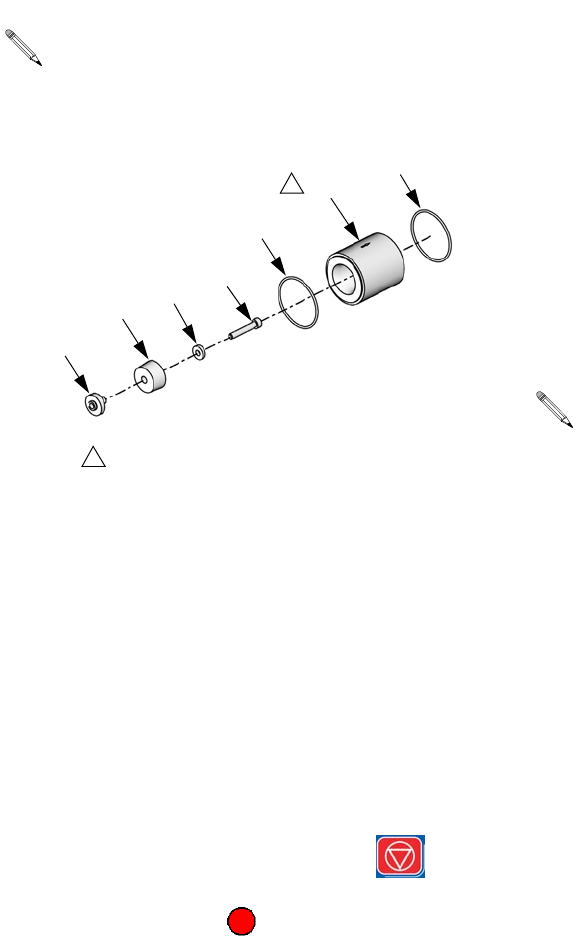
9. Place the new check valve ball guide (2103) on a
bench with the open end up. Install the check valve
spring (2102) into the guide.
10. Install the check valve ball (2101) on top of the
spring (2101).
11. Place the seat (2104) on top of the check valve
ball (2101) with the outside chamfered side of the
seat facing away from the check valve ball.
12. Hold both ends of the assembled check valve
assembly and install the check valve into the
unthreaded end of the check valve housing (513)
with the ball end facing out. See FIG. 9 on page 33.
13. Apply pressure to the valve to snugly fit the assem-
bled check valve (514) into the check valve
housing (513). Fit the check valve seat (2104) into
the valve guide. See FIG. 9 on page 33.
14. Use a wrench to insert the new valve and valve
housing into the pump end cap (508).
15. Install the material male hose fitting into the check
valve housing using a wrench.
16. Before operating the machine, activate a few shots
to purge any air present in the material hose lines.
17. Calibrate the machine if necessary. See the appro-
priate operation manual referenced at the beginning
of this manual for procedure.
See Pump Sub-Assembly, LC0112, page 54 for
pump sub-assembly part references. See Kits on
page 80 for kit numbers.
FIG. 10: Check Valve Rebuild Kit
1
Side of seat with outside chamfer must face away
from ball. Side of seat with inner radius must face the
ball.
1
2104
2101
2102
2103
ti12565a
Outside
Chamfer
Inner Radius
Verify when the assembled check valve (514) and
housing (513) are turned up-side down that the
contents of the check valve stay in place.
Repair
312760S 37
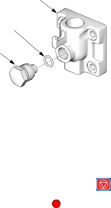
Piston Plug Installation
1. Drain the pump.
•If ball valves are installed, close the ball
valves then take several shots.
•If ball valves are not installed, empty the
tanks. Perform shots repeatedly until no mate-
rial comes out of the dispense valve.
2. Relieve pressure. See Pressure Relief Procedure,
page 14.
3. Models with ADM: To prevent machine movement,
press the Machine Disable Mode key ( ).
Models with SDM: To prevent machine movement,
press the Red button .
4. Use a wrench to remove the existing piston
plug (1801) from the pump end cap (508).
5. Remove the existing o-ring (1802).
6. Lubricate the new o-ring with a high temperature
grease (part 115982) and install the lubricated
o-ring into the end cap.
7. Install pump plug (1801) into end cap.
8. Open the tank ball valves if installed.
9. Fill tanks.
10. Perform several shots to fill the pump with new
material.
Pressure Transducer Installation
NOTE: The pressure transducers are designed to work
with the hoses available in the PR70 configurator. If they
are used with other hoses, unexpected alarms may
occur.
1. Follow steps 1 through 6 of Piston Plug Installa-
tion on this page.
2. Remove shield locking screws (2202, 2409) then
remove shield (117, 214).
3. Install hex end of pressure transducer into end
cap (508).
4. For A side pressure transducers, install data
cable end of pressure transducer into port #6 of
Fluid Control Module #1. See FIG. 5, page 27.
For B side pressure transducers, install data
cable end of pressure transducer into port #7 of
Fluid Control Module #1. See FIG. 5, page 27.
5. Install shield and shield locking screws.
6. Follow steps 8 through 10 of Piston Plug Installa-
tion on this page.
1802
1801
ti12562a
508
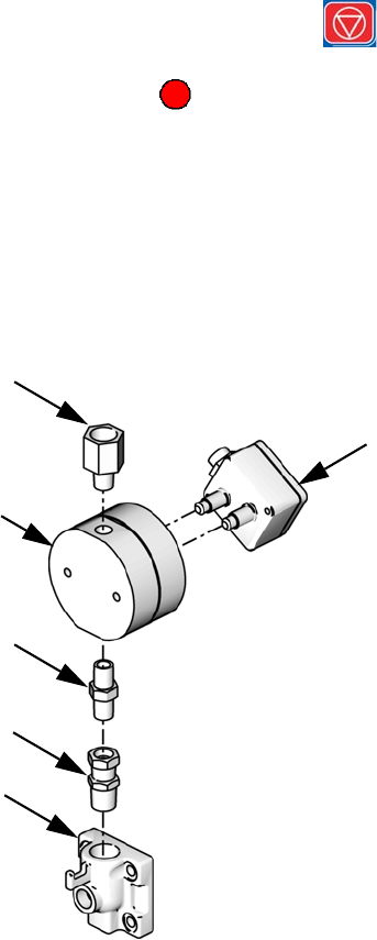
Repair
38 312760S
Flow Meter Installation
1. Drain the pump.
•If ball valves are installed, close the ball
valves then take several shots.
•If ball valves are not installed, empty the
tanks. Perform shots repeatedly until no mate-
rial comes out of the dispense valve.
2. Relieve pressure. See Pressure Relief Procedure,
page 14.
3. Models with ADM: To prevent machine movement,
press the Machine Disable Mode key ( ).
Models with SDM: To prevent machine movement,
press the Red button .
4. Remove shield locking screws (2202, 2409) then
remove shield (117, 214).
5. Use a wrench to remove fluid lines from top of pump
end cap (508).
6. Use fittings (2004, 2005) to install flow meter
body (2001) onto end cap (508). See following
image.
7. Install remaining fitting (2003) onto top of flow
meter. See preceding image.
8. Install flow meter sensor (2002) onto flow meter
body (2001).
9. Install fluid lines into fitting (2003) on top of flow
meter.
10. For side A flow meters, plug flow meter sensor
cable into port #1 on Fluid Control Module #2.
For side B flow meters, plug flow meter sensor
cable into port #2 on Fluid Control Module #2.
11. Open the tank ball valves if installed.
12. Install shield and shield locking screws.
13. Fill tanks.
14. Perform several shots to fill the pump with new
material and to prime the flow meters.
ti13898a
2002
2003
2001
2004
2005
508
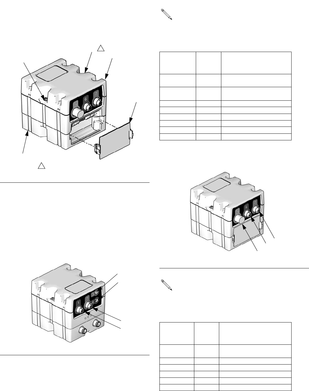
Repair
312760S 39
Fluid Control Module
Replacement
1. Remove access cover (D).
2. Remove two screws (C) and FCM (A) from base (B).
3. Mount base (B) to system with four screws. Insert
screws through top of base and tighten to system.
4. Mount FCM (A) on base (B) with two screws (C).
5. Connect cables to front of fluid control module. See
FIG. 12 and the following table.
6. Connect cables to rear of fluid control module. See
FIG. 13 and the following table.
FIG. 11
FIG. 12: Fluid Control Module Front Connections
D
C
CA
B
1
Not visible from current angle.
1
ti12334a
ti12337a
1
3
4
2
If there is only one fluid control module on the
machine, the module number is 1.
If there are two fluid control modules, the mod-
ule closest to the air regulator is module number 1
and the other module is number 2.
Connection
Reference
(FIG. 12)
Module
Number Connects To
1 1 Footswitch or
PLC Interface
2 1 Footswitch or
PLC Interface
3 1 Tank Low Level Sensor A
4 1 Tank Low Level Sensor B
1 2 Flow Meter A
2 2 Flow Meter B
3 2 Tank High Level Sensor A
4 2 Tank High Level Sensor B
FIG. 13: Fluid Control Module Rear Connections
If there is only one fluid control module on the
machine, the module number is 1.
If there are two fluid control modules, the mod-
ule closest to the air regulator is module number 1
and the other module is number 2.
Connection
Reference
(FIG. 13)
Module
Number Connects To
5 1 Dispense Valve and
Linear Position Sensor
6 1 Pressure Transducer A
7 1 Pressure Transducer B
5 2 Auto-Fill Valve
6 2 Not Used
7 2 Not Used
ti12336a
5
67
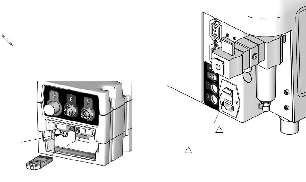
Repair
40 312760S
7. If there is only one fluid control module on the
machine, set the rotary switch (S) to 1. See FIG. 14.
If there are two fluid control modules, set the
rotary switch (S) to 1 on the module closest to the
air regulator and set the rotary switch (S) to 2 on the
other module. See FIG. 14.
8. Install access cover (D).
Fuse Replacement
1. Remove incoming power cord from machine.
2. Insert a flat-head screw-driver between the fuse
holder and the back of the incoming power bracket
remove machine fuse holder.
3. Remove the blown fuse from the machine fuse
holder.
4. Install new fuse with same rating into the fuse
holder.
5. Install the fuse holder into the Incoming Power
Bracket.
The rotary switch setting must only be adjusted on
new fluid control modules after installation. The
rotary switch setting indicates the fluid control mod-
ule number being replaced. The fluid control mod-
ule uses a 16-position rotary switch.
FIG. 14
S
ti12335a
Fuse Holder
Fuse holder is located between the
power connector and power switch.
1
1
ti12563a
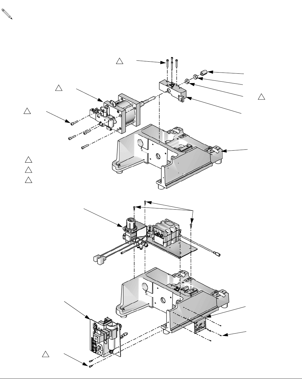
Parts
312760S 41
Parts
Fixed Ratio Base, LC0262, LC0263, LC0264, LC0265
See Feed Systems manual for feed system parts.
See Related Manuals on page 3.
FIG. 15
100d
100b
107
105
106
108
103
104
Torque to 85 in-lb (9.6 N•m).
Torque to 350 in-lb (39.5 N•m).
Torque to air cylinder shaft
to100 ft-lb (135 N•m).
1
2
3
2
3
2
3
ti12436a
111
110
109
118
119
1ti12486a
109
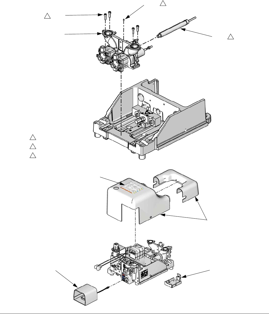
Parts
42 312760S
Fixed Ratio Base, continued
FIG. 16
100a
100c
102
101
Torque to 85 in-lb (9.6 N•m).
Torque to 350 in-lb (39.5 N•m).
Retaining ring must rest against
pump body.
1
2
4
2
1
4
ti12487a
117
112
120
ti12476b
117a

Parts
312760S 43
*Not shown.
▲Replacement Danger and Warning labels, tags, and cards are available at no cost.
Ref Part Description Qty
100a 120920 SHOCK ABSORB, adjustable
(models LC0263 and LC0265 only)
1
100b 120919 NUT, hex
(models LC0263 and LC0265 only)
1
100c 111260 SCREW, set, cup point
(models LC0263 and LC0265 only)
1
100d 15K816 CAP, adjustment, Hydracheck
(models LC0263 and LC0265 only)
1
101 LC0112 PUMP, sub-assembly 1
102 120913 SCREW 4
103 120919 NUT, hex 1
104 LC0107 BLOCK, assembly, drive 1
105 121166 SCREW 4
106 LC0110 CYLINDER, air, sub-assembly, 3.0 in.
(models LC0262 and LC0263 only)
1
LC0111 CYLINDER, air, sub-assembly, 4.5 in.
(models LC0264 and LC0265 only.)
1
107 LC0290 FRAME, sub, assembly 1
108 121167 SCREW 4
109 120885 SCREW 6
110 LC0239 BRACKET, incoming power, sub-assy 1
111 LC0261 BRACKET, controls, assembly 1
112 255235 BRACKET, mounting, assembly 1
114 * 121597 CABLE, CAN, 90 female / 90 female 1
115 * 61/2906-BK/11 TUBE, air, 3/8 in. OD 2
116 * 61/2904-BK/11 TUBE, air, 1/4 in. OD 2
117 LC0308 SHIELD, assembly 1
117a ▲15M511 LABEL, shield 1
118 84/0001-6/11 TAG, ID 1
119 96/0235/98 SCREW, drive, type U, #2 X 3/16 stainless
steel
4
120 255244 SWITCH, foot, assembly 1
127 * LC0135 MODULE, TOKEN, PR70 1
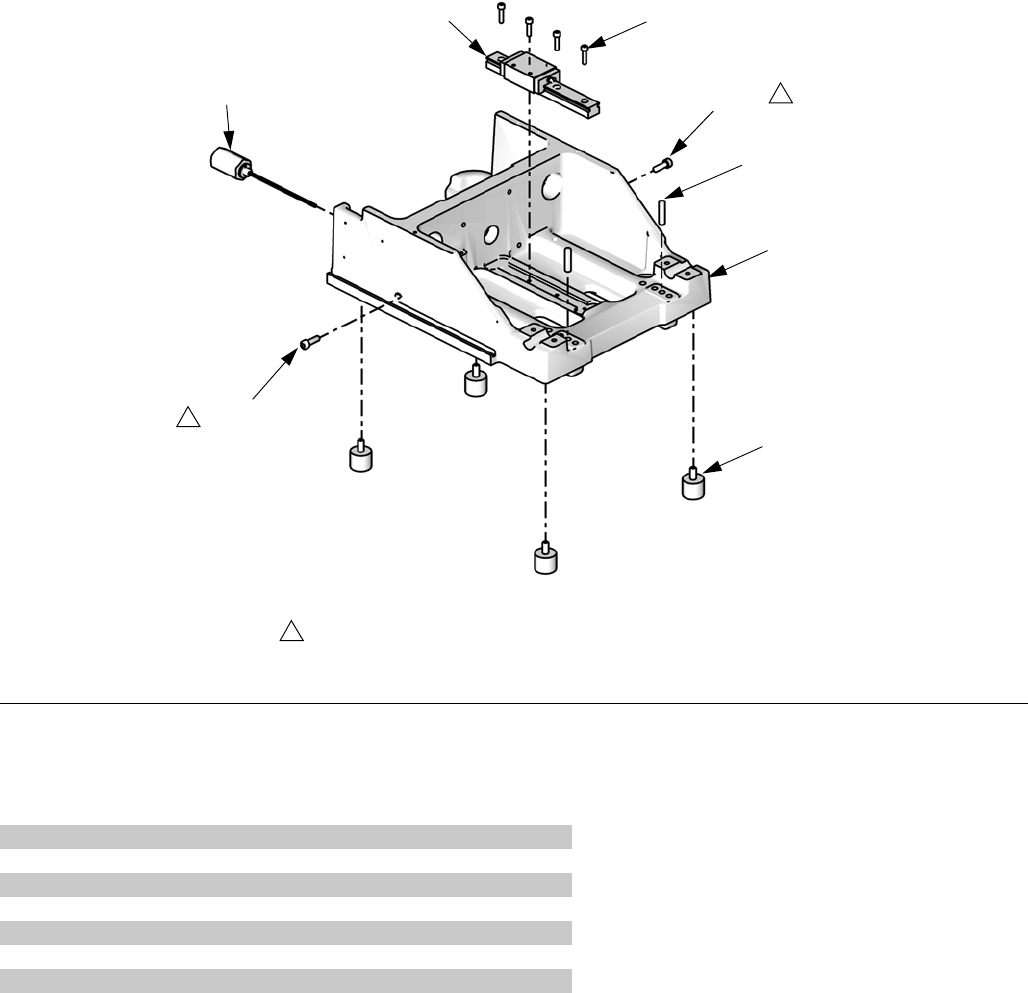
Parts
44 312760S
Fixed Ratio Frame Sub-Assembly, LC0290
FIG. 17
Ref Part Description Qty
2201 120599 PIN, dowel 2
2202 120913 SCREW 2
2203 15K788 FRAME, base, machined 1
2204 LC0234 SENSOR, assembly 1
2205 120918 BEARING, linear, slide 1
2206 120886 SCREW 4
2207 96/0507/11 BUMPER, rubber, 3/8-16 x 0.63 4
Apply anti-seize compound (part 073025) to screws.
1
2201
ti12572a
1
2206
2202
2202
2205
2204
2203
2207
1
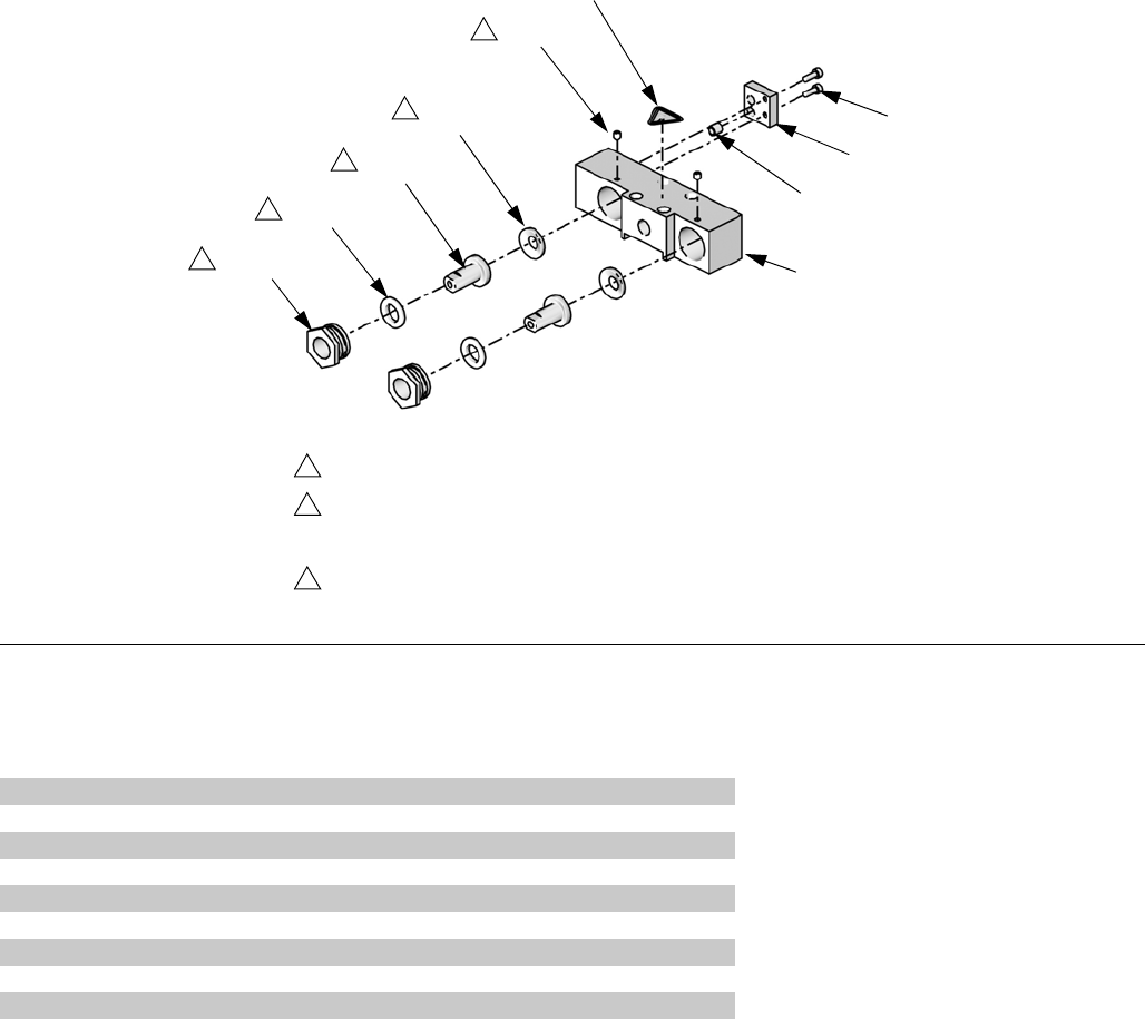
Parts
312760S 45
Fixed Ratio Drive Block
Assembly, LC0107
▲Replacement Danger and Warning labels, tags, and cards are available at no cost.
FIG. 18
Apply grease (part 115982) to all internal parts.
Tighten retaining nut until alignment rod (2302) cannot be moved.
Loosen retaining nut until alignment rod can move side-to-side with
no in-and-out movement.
Torque to 64 in-lb (7.2 N•m).
1
2
3
2308
2
ti12573a
2307
2309
2306
2305
2302
2305
2303
1
1
1
2301
3
2304
Ref Part Description Qty
2301 120891 SCREW, set, socket, cone point 2
2302 15K801 ROD, alignment 2
2303 15K802 RETAINER, nut 2
2304 15K805 BLOCK, drive 1
2305 15K868 WASHER, female, male modified, assembly 2
2306 ▲84/0130-27/11 LABEL, warning, pinch point 1
2307 15T389 BRACKET, mounting, magnet 1
2308 120885 SCREW 2
2309 15G747 MAGNET, linear sensor 1
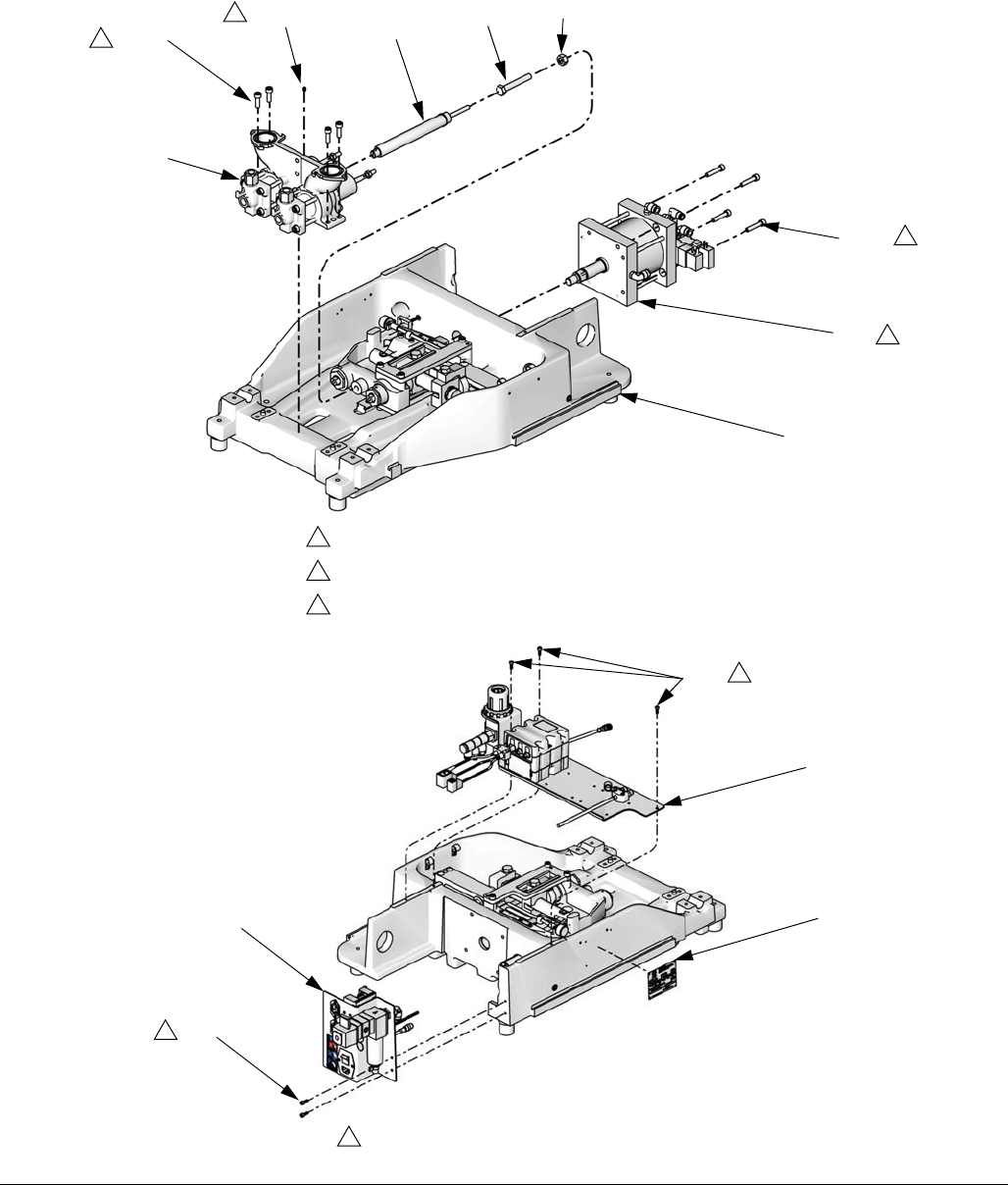
Parts
46 312760S
Variable Ratio Base, LC0242, LC0243, LC0244, LC0245
FIG. 19
203
208
200b 200a 200c 200d
209
202
201
Torque to 85 in-lb (9.6 N•m).
Torque to 350 in-lb (39.5 N•m).
Torque to air cylinder shaft to100 ft-lb (135 N•m).
1
2
3
2
1
3
2
ti12437a
207
205
210
204
207
1
1
ti12488b
Torque to 85 in-lb (9.6 N•m).
1
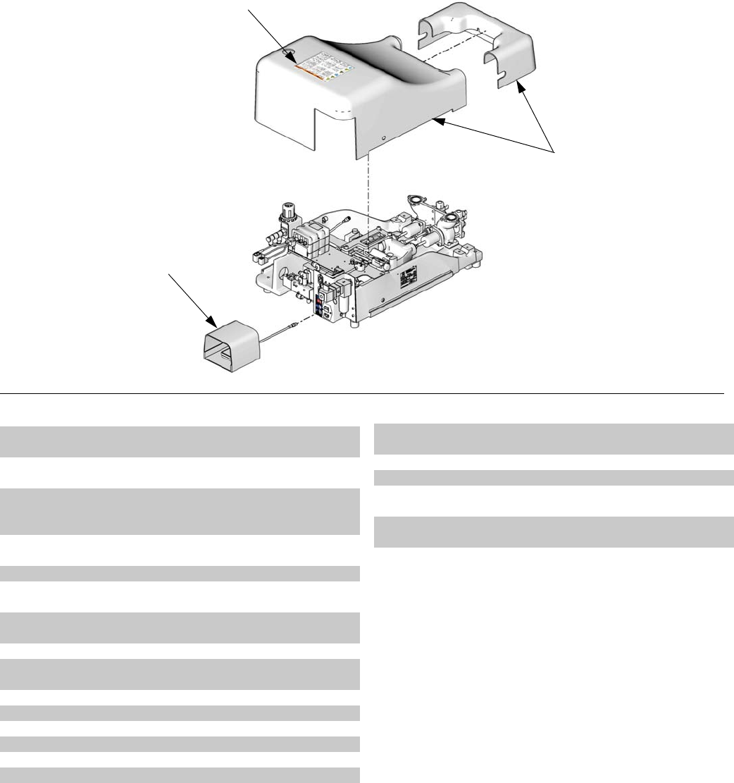
Parts
312760S 47
Variable Ratio Base continued
*Not shown.
▲Replacement Danger and Warning labels, tags, and
cards are available at no cost.
FIG. 20
214
206
ti12475b
214a
Ref Part Description Qty
200a 120920 SHOCK ABSORB, adjustable
(models LC0243 and LC0245 only)
1
200b 111260 SCREW, set, cup point
(models LC0243 and LC0245 only)
1
200c 121589 SCREW, hex head cap, M12 x
1.75, 80 mm long
(models LC0243 and LC0245 only)
1
200d 107539 NUT, hex
(models LC0243 and LC0245 only)
1
201 LC0232 FRAME, sub-assembly 1
202 LC0230 CYLINDER, air, 3.0 in. diameter
(models LC0242 and LC0243 only)
1
LC0231 CYLINDER, air, 4.5 in. diameter
(models LC0244 and LC0245 only)
1
203 LC0112 PUMP, sub-assembly 1
204 LC0239 BRACKET, incoming power,
sub-assy
1
205 LC0240 BRACKET, control, sub-assembly 1
206 255244 SWITCH, foot, assembly 1
207 120885 SCREW 5
208 120913 SCREW 4
209 121167 SCREW 4
210 16D782 LABEL 1
212 61/2904-BK/11 HOSE, 0.160 ID x 0.250 OD, PU,
95 DUR
1
213 61/2906-BK/11 HOSE, 0.245ID x 0.375 OD, PU, 95
DUR
1
214 LC0246 SHIELD, assembly 1
214a ▲15M511 LABEL, shield 1
215 * 124002 PROTECTOR, wire, corrugated,
5/8 in. ID
8
* 124002 PROTECTOR, wire, corrugated,
5/8 in. ID
5
Ref Part Description Qty

Parts
48 312760S
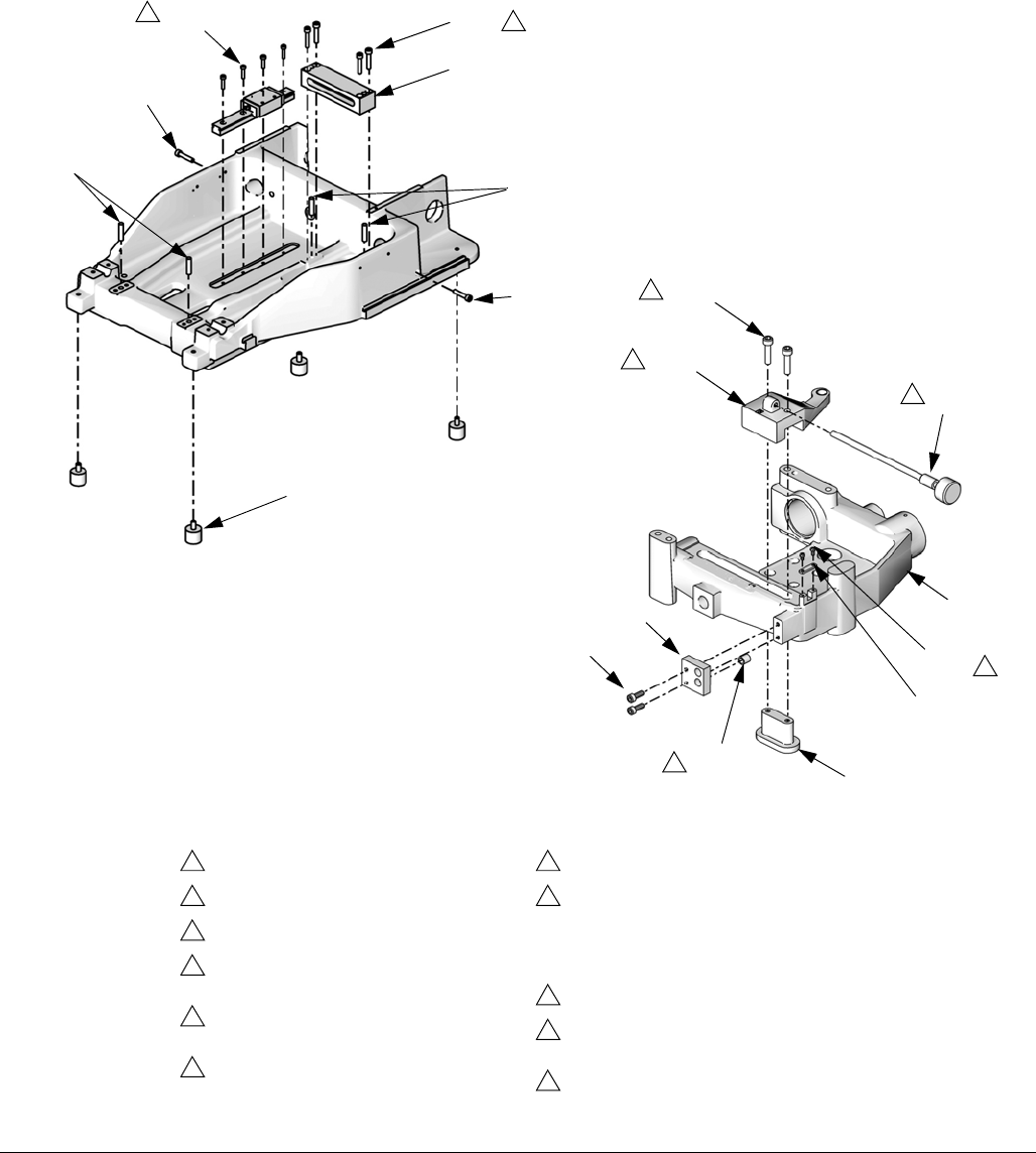
Parts
312760S 49
Variable Ratio Frame Sub-Assembly, LC0232
FIG. 21
2409
ti12568a
ti12569a
2406
2409
2409
2436
2404
2404
2430
2406
2416
2417
2415
2432
2405
2427
2418
2401
2426
5
2
1
5
1
7
10
Torque screws to 140 in-lb (15.8 N•m).
Torque screws to 350 in-lb (39.5 N•m).
Torque stud to 780 in-lb (88.1 N•m).
Ref 2414 and 2428 must be oriented as
shown.
Lubricate bearing and threaded
surfaces with 115982.
Torque to 35 in-lb (3.9 N•m).
Torque to 8 in-lb (0.9 N•m).
Tighten retaining nut until alignment rod
(2419) cannot be moved. Then loosen
retaining nut until alignment rod can
move side to side with no in-and-out
movement.
Torque to 19 in-lb (2.1 N•m).
Bond 2418 into 2427 using adhesive,
part 071023.
Press fit 2403 into 2424.
1
2
3
4
5
6
7
8
9
10
11
Drive Block Rear Parts
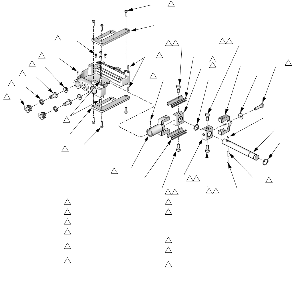
Parts
50 312760S
Variable Ratio Frame Sub-Assembly continued
FIG. 22
ti12571a
2407
Torque screws to 140 in-lb (15.8 N•m).
Torque screws to 350 in-lb (39.5 N•m).
Torque stud to 780 in-lb (88.1 N•m).
Ref 2414 and 2428 must be oriented as
shown.
Lubricate bearing and threaded
surfaces with 115982.
Torque to 35 in-lb (3.9 N•m).
Torque to 8 in-lb (0.9 N•m).
Tighten retaining nut until alignment rod
(2419) cannot be moved. Then loosen
retaining nut until alignment rod can
move side to side with no in-and-out
movement.
Torque to 19 in-lb (2.1 N•m).
Bond 2418 into 2427 using adhesive,
part 071023.
Press fit 2403 into 2424.
1
2
3
4
5
6
7
8
9
10
11
2424
2403
2410
2421
2419
2421
2420
2407
2424
2425
2435
2425
2429
2434
2402
2422
2412
2411
2411
2423
2425
2435
2428
2412
2414
2414
2413
2
1
4
53
53 53
54 3
5
4
2
2
11
2413
9
9
5
5
5
8
Drive Block Front/Side Parts
2403 11
2425 53

Parts
312760S 51
*Not shown.
▲Replacement Danger and Warning labels, tags, and
cards are available at no cost.
Ref Part Description Qty
2401 119912 SCREW, machined, phillips
pan head
2
2402 107596 SCREW, cap, hex head 1
2403 116193 PIN, dowel, 1/4 x 3/4 4
2404 120599 PIN, dowel 4
2405 120885 SCREW 2
2406 120886 SCREW 6
2407 120913 SCREW 6
2408 120918 BEARING, linear, slide 1
2409 121167 SCREW 6
2410 121518 SCREW, socket head cap 4
2411 121524 RING, retaining 2
2412 121529 RING, retaining,1-1/8 in., snap 2
2413 121530 SCREW, set, socket head cap,
M4 x 5, cone point
2
2414 256264 BLOCK, assembly, slide,
beam, ratio
2
2415 256268 CARRIAGE, assembly, slide,
beam, ratio
1
2416 256280 ARM, assembly, adjustment 1
2417 256288 KNOB, ratio adjustment 1
2418 15G747 MAGNET, linear sensor 1
2419 15K801 ROD, alignment 2
2420 15K802 RETAINER, nut 2
2421 15K868 WASHER, female, male modi-
fied, assembly
2
2422 15T377 BAR, ratio, beam 1
2423 15T383 PIN, pivot, beam, ratio 1
2424 15T384 PLATE, guide, ratio 2
2425 15T385 STUD, clevis, beam 4
2426 15T388 RETAINER, knob, adjust 1
2427 15T389 BRACKET, mounting, magnet 1
2428 15T448 CLEVIS, moving, machined 1
2429 15T449 CLEVIS, fixed, machined 1
2430 15T463 BRACKET, bar, pivot 1
2431 15T626 FRAME, base, machined 1
2432 15T715 NUT, locking, ratio adjustment 1
2433 LC0234 SENSOR, assembly 1
2434 119438 WASHER, flat 1
2435 15U196 BEARING, strip 4
2436 121573 BUMPER, urethane, 3/8-16 4
2499 ▲* 84/0130-
27/11
LABEL, warning, pinch point 1
Ref Part Description Qty
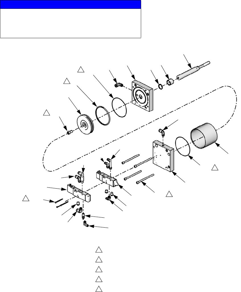
Parts
52 312760S
Air Cylinder, LC0110, LC0111, LC0230, LC0231
NOTICE
The four long screws (404) that attach the two drive
blocks (417, 418) must be tightened in a crisscross
pattern. Failure to do so may result in air cylinder
damage.
416
411
418
404
414
415
409†
410
412
414
402
407
412
422
415
413
412
420
405
401
417
412
411
403
419
406
408
Torque to 41 in-lb (4.6 N•m).
Torque to 350 in-lb (39.5 N•m).
Torque to 100 ft-lb (135 N•m).
Coat all sliding surfaces with lubricant, part 115982.
Apply sealant tape to npt fittings.
1
2
3
4
5
2
1
4
4
4
ti12490a
3

Parts
312760S 53
† When replacing the muffler, adjust the muffler setting
so that the pistons take approximately 1/2 to 1 sec-
ond to retract.
Ref Part Description Qty
401 107571 PACKING, o-ring 1
402 114100 SCREW, cap, socket hd 3
403 120875 O-RING, 3 in. (assemblies LC0110
and LC0230)
1
104131 O-RING, 4.5 in. (assemblies
LC0111 and LC0231)
1
404 120880 SCREW 4
405 120881 BEARING 1
406 120884 SCREW 1
407 120899 VALVE, solenoid, 3 way 1
408 120900 VALVE, solenoid, 3 way 1
409 † 120922 MUFFLER, w/ integral flow control 1
410 120923 FITTING, elbow, male, swivel 1
411 120932 O-RING (assemblies LC0110 and
LC0230 only)
2
104271 PACKING, o-ring (assemblies
LC0111 and LC0231 only)
2
412 121018 FITTING, elbow, male, swivel,
1/4 npt
5
413 121020 FITTING, elbow, male, swivel,
1/4 npt
1
414 121021 MUFFLER, 1/4 npt 3
415 121022 FITTING, elbow, male, 1/4 npt 2
416 15K790 TUBE, air, cylinder, 3.0 (assem-
blies LC0110 and LC0230 only)
1
15K789 TUBE, air, cylinder, 4.5 (assem-
blies LC0111 and LC0231 only)
1
417 15K791 BLOCK, air cylinder, rod end 1
418 15K792 BLOCK, air cylinder, blind end 1
419 15K793 PISTON (assemblies LC0110 and
LC0230 only)
1
15K794 PISTON (assemblies LC0111 and
LC0231 only)
1
420 15K795 ROD, piston, air cylinder (assem-
blies LC0110 and LC0111 only)
1
15T714 ROD, piston, air cylinder (assem-
blies LC0230 and LC0231 only)
1
422 121643 FITTING, elbow, 1/4 x 1/4 npt,
swivel, ext (assemblies LC0230
and LC0231 only)
1
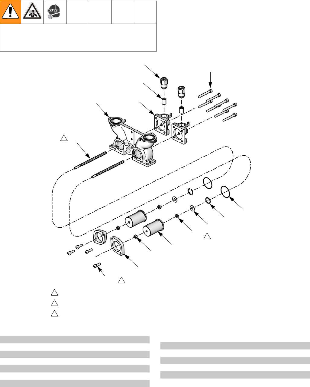
Parts
54 312760S
Pump Sub-Assembly, LC0112
The pump shaft is installed with Krytox. Contact with
Krytox can lead to flu-like symptoms. The MSDS for this
material is available upon request.
506
513
514
508
507
511
501
504
512
503
510
502
509
505
Torque to 350 in-lb (39.5 N•m).
Lube shaft with krytox grease prior to insertion into bearing.
Shaft seal (503) must be installed with open side facing the washer (512).
1
2
3
2
1
3
ti12491a
Ref Part Description Qty
501 106258 PACKING, o-ring 2
502 108712 NUT, hex 2
503 120887 SEAL, posipak, 3/8 x 5/8, uhmwpe 2
504 120890 RING, retaining 2
505 120913 SCREW 4
506 120982 SCREW 8
507 15K786 HOUSING, pump 1
508 15K787 CAP, end, pump, machined 2
509 15K803 COLLAR 2
510 15K804 HOUSING, bearing, seal 2
511 15K824 ROD, piston 2
512 15K828 WASHER, housing, seal 2
513 15K895 HOUSING, check valve 2
514 LC0093 KIT, rebuild, valve, check 2
Ref Part Description Qty
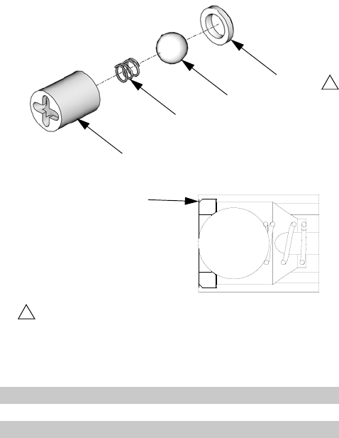
Parts
312760S 55
Check Valve, Assembly LC0093
Ref Part Description Qty
2101 105445 BALL, 0.5000 1
2102 121084 SPRING 1
2103 15D312 BUSHING, ball guide 1
2104 196832 SEAT, lapped 1
1
The side of the seat with an outside diameter chamfer
must point away from the ball.
1
2104
2101
2102
2103 ti12565a
Chamfer
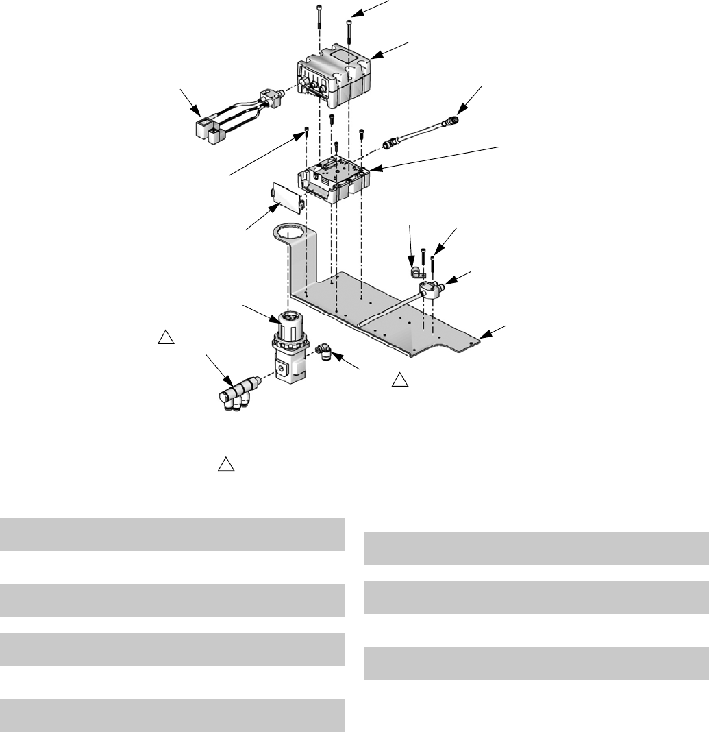
Parts
56 312760S
Control Bracket, LC0240, LC0261
*Not shown.
▲Replacement Danger and Warning labels, tags, and cards are available at no cost.
When purchasing a replacement fluid control module, software token 15W046 is required to install software
before first use.
Apply thread sealant tape to male npt threads.
1
2513b
ti12568a
1
Assembly LC0240 Shown
2513a
2510
2512
2505
2511
2501
2508
2509
2506
2507
2503
2502
2504
1
Ref Part Description Qty
2501 15T735 BRACKET, control mounting
(assembly LC0240 only)
1
15U737 BRACKET, control mounting
(assembly LC0261 only)
1
2502 120897 REGULATOR, air, with integral
gage
1
2503 120954 MANIFOLD, inlet, banjo 1
2504 121018 FITTING, elbow, male, swivel,1/4
NPT
1
2505 LC0291 CABLE, power
(assembly LC0240 only)
1
2506 113003 SCREW, socket head cap,10-32 x
0.62, stainless steel
4
2507 289697 BASE, Fluid Control Module 1
2508 121583 HARNESS, I/O, M12 x M8 x sub-
micro x mini
1
2509 277674 ENCLOSURE, cube door 1
2510 121685 CABLE, CAN, M12 x M12, 5P,
female-female, straight x right
1
2511 121860 SCREW, M4 x 0.7, 30 mm long,
stainless steel
2
2512 84/0153-
1/89
CLAMP, harness, nylon 1
2513289696 MODULE, Fluid Control, assembly 1
Ref Part Description Qty

Parts
312760S 57
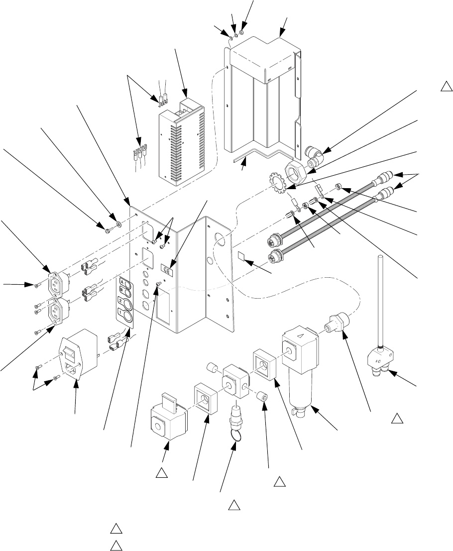
Parts
58 312760S
Incoming Power Bracket, LC0239
303
326
307
326
307
306, 318
313
314
316
317
314
304
Apply thread sealant tape if applicable.
Vent direction must point toward machine.
1
2
ti17531b
309
310
302
305
330
1
1
1
1
2
311
308
325
312
308
329
336
334
333 338
337
333
335
308
Ground
from
306
Ground
from
319
Ground
from
303
301
301
Part of
331

Parts
312760S 59
*Not shown.
--- Not for sale.
Ref Part Description Qty
301 119912 SCREW, mach. phillips pan
hd.
3
302 121018 FITTING, elbow, male,
swivel, 1/4 npt
1
303 120876 POWER SUPPLY 1
304 120882 FILTER 1
305 120883 NUT 1
306 120910 SOCKET, electrical, with EMI
filter
1
307 120916 SCREW 6
308 120993 NUT, hex, M5, with tooth
washer
2
309 15U738 BRACKET, incoming power 1
310 15K800 FITTING, bulkhead 1
311 * 84/0130-26/11 LABEL, symbol, pe 1
312 121581 HARNESS, I/O, M12 x M12 2
313 121178 VALVE, 1/4 in. OSHA lockout 1
314 121179 CLAMP 2
315 * 121180 MANIFOLD 1
316 94/0762/99 VALVE, safety, blow-off,
100 psi
1
317 94/0430/99 PLUG, pipe, 1/4 npt 2
318 81/1054-4/11 FUSE, type f, 4 amp, 250v,
fast
2
319 LC0291 CABLE, power, assembly 1
325 * 84/2725-1/11 LABEL, symbol, CE 1
326 121558 CONNECTOR, power, panel
mount
2
329 15V092 LABEL, bracket, incoming,
power
1
330 104395 WASHER, lock, tooth, exter-
nal
1
331 24F228 HARNESS, wire 1
332 --- SEALANT, pipe 1
333 122664 WASHER, back-up 8
334 100068 WASHER, lock, spring 4
335 125609 FASTENER, screw, shcs, M3
x 0.5 x 10, stainless steel
4
336 125104 NUT, hex, M3 4
337 114225 TRIM, edge protection 0.5
338 24J864 PARTITION, power 1
Ref Part Description Qty
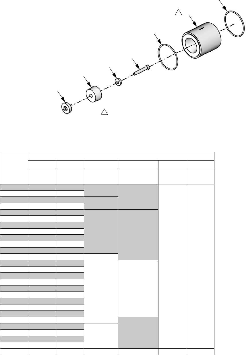
Parts
60 312760S
Piston Package
Nylon Piston, Stainless Steel Metering Tube
Assemblies
606
601
606
605
603
602
604
ti12438a
Arrow on cylinder must point to the o-ring (606) on the right.
1
1
Piston
Package
Reference Number and Description
601 602 603† 604 605 606
Tube,
pump
Nylon
Piston Washer
Ring, support,
piston Screw O-ring
LC1080 LCC080 LCB080 15M089
120933 120874
LC1100 LCC100 LCB100
LC1120 LCC120 LCB120
LC1140 LCC140 LCB140
LC1160 LCC160 LCB160
15M099 15K887
LC1180 LCC180 LCB180
LC1200 LCC200 LCB200
LC1220 LCC220 LCB220
LC1240 LCC240 LCB240
LC1260 LCC260 LCB260
LC1280 LCC280 LCB280
LC1300 LCC300 LCB300
15M100
LC1320 LCC320 LCB320
15K888
LC1340 LCC340 LCB340
LC1360 LCC360 LCB360
LC1400 LCC400 LCB400
LC1440 LCC440 LCB440
LC1480 LCC480 LCB480
LC1520 LCC520 LCB520
LC1560 LCC560 LCB560
LC1600 LCC600 LCB600
LC1640 LCC640 LCB640
15K890
LC1720 LCC720 LCB720
15M101
LC1800 LCC800 LCB800
LC1880 LCC880 LCB880
LC1960 LCC960 LCB960
Quantity 11 1 1 12

Parts
312760S 61
UHMW Piston, Stainless Steel Metering
Tube Assemblies
Piston
Package
Reference Number and Description
601 602 603† 604 605 606
Tube,
pump
UHMW
Piston Washer
Ring, support,
piston Screw O-ring
LC2160 LCC160 LCA160
15M099 15K887
120933 120874
LC2180 LCC180 LCA180
LC2200 LCC200 LCA200
LC2220 LCC220 LCA220
LC2240 LCC240 LCA240
LC2260 LCC260 LCA260
LC2280 LCC280 LCA280
LC2300 LCC300 LCA300
15M100
LC2320 LCC320 LCA320
15K888
LC2340 LCC340 LCA340
LC2360 LCC360 LCA360
LC2400 LCC400 LCA400
LC2440 LCC440 LCA440
LC2480 LCC480 LCA480
LC2520 LCC520 LCA520
LC2560 LCC560 LCA560
LC2600 LCC600 LCA600
LC2640 LCC640 LCA640
15K890
LC2720 LCC720 LCA720
15M101
LC2800 LCC800 LCA800
LC2880 LCC880 LCA880
LC2960 LCC960 LCA960
Quantity 11 1 1 12

Parts
62 312760S
UHMW Piston, Ceramic Metering Tube
Assemblies
NOTE: The UHMW piston, ceramic metering tube
assemblies contain a carbide ball. This ball replaces the
standard check valve ball in pump assembly LC0112. If
a UHMW piston, ceramic metering tube assembly needs
to be installed, replace the original ball in pump assem-
bly LC0112 with the ball included with the pump pack-
age. See Check Valve Rebuild Kit Installation on
page 36 for installation instructions.
† For custom piston packages, washer (603) part number will change by piston size as follows:
For piston sizes 80-100cc: 15M089
For piston sizes 101-159cc: Washer not used.
For piston sizes 160-285cc: 15M099
For piston sizes 286-646cc: 15M100
For piston sizes 647-960cc: 15M101
Piston
Package
Reference Number and Description
601 602 603† 604 605 606 607
Tube,
pump
UHMW
Piston Washer
Ring, support,
piston Screw O-ring
Carbide
Ball
LC3160 LCG160 LCA160
15M099 15K887
120933 120874 116166
LC3180 LCG180 LCA180
LC3200 LCG200 LCA200
LC3220 LCG220 LCA220
LC3240 LCG240 LCA240
LC3260 LCG260 LCA260
LC3280 LCG280 LCA280
LC3300 LCG300 LCA300
15M100
LC3320 LCG320 LCA320
15K888
LC3340 LCG340 LCA340
LC3360 LCG360 LCA360
LC3400 LCG400 LCA400
LC3440 LCG440 LCA440
LC3480 LCG480 LCA480
LC3520 LCG520 LCA520
LC3560 LCG560 LCA560
LC3600 LCG600 LCA600
LC3640 LCG640 LCA640
15K890
LC3720 LCG720 LCA720
15M101
LC3800 LCG800 LCA800
LC3880 LCG880 LCA880
LC3960 LCG960 LCA960
Quantity 11 1 1 121
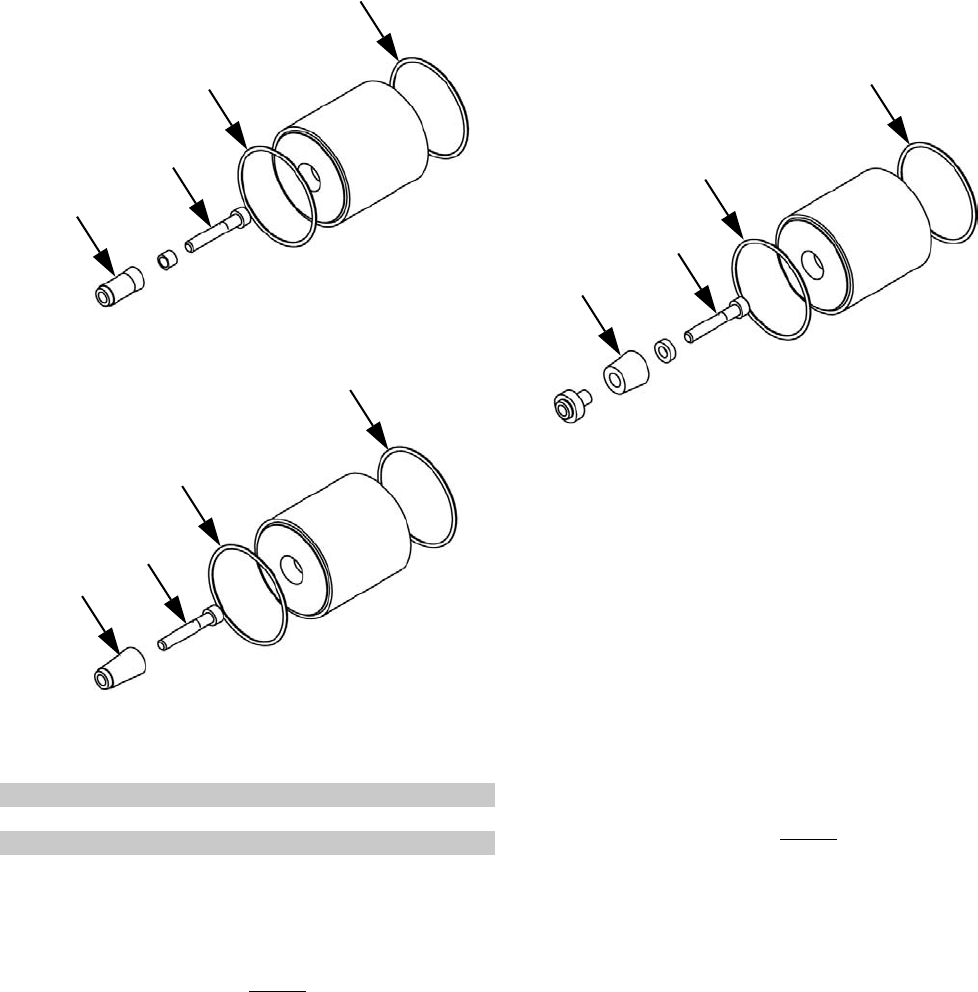
Parts
312760S 63
Nylon and UHMW Piston Replacement Kits
When ordering a piston replacement kit, the following
intelligent part numbering system applies for Nylon
based pistons.
When ordering a UHMW replacement kit, the following
numbering applies:
The items indicated above will be supplied with the kit.
See the Product Configurator section beginning on
page 4 for available standard piston sizes.
651
652
653
653
652
653
653
651
652
653
653
651
Piston Sizes 080-119
Piston Sizes 120-159
Piston Sizes 160-960
Ref Part Description Qty
651 PISTON 1
652 SCREW 1
653 O-RING 2
LCF - 160
Code: A
Piston Size (mm2)
LCE - 160
Code: A
Piston Size (mm2)
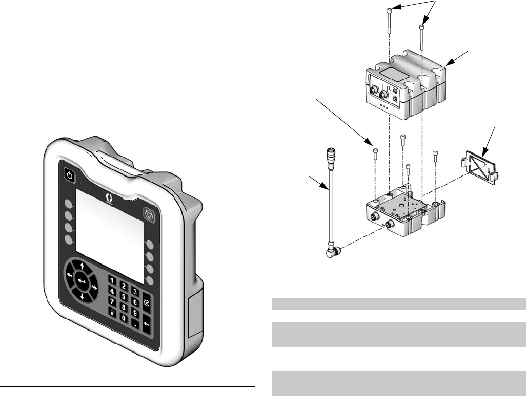
Parts
64 312760S
Controls
There are three options for controls.
• Advanced Display Module with one Fluid Control
Module, LC0274★
• Advanced Display Module with two Fluid Control
Modules, LC0275★
• Standard Display Module with one Fluid Control
Module, LC0272
★A protective, membrane shield 15V551 is available
for the screen and softkeys of the Advanced Display
Module.
Fluid Control Module
When purchasing a replacement fluid control mod-
ule, software token 15W046 is required to install soft-
ware before first use.
FIG. 23: Advanced Display Module, 24E451
ti12362a
Ref Part Description Qty
701 289697 MODULE, base 1
702 277674 ENCLOSURE, door 1
703 121597 CABLE, CAN, 90 female / 90
female
1
704 113003 SCREW, socket head cap,
10-32 x 0.62, stainless steel
4
705289696 MODULE, assembly,
Fluid Control Module
1
705b
705a
702
703
704
ti12711a
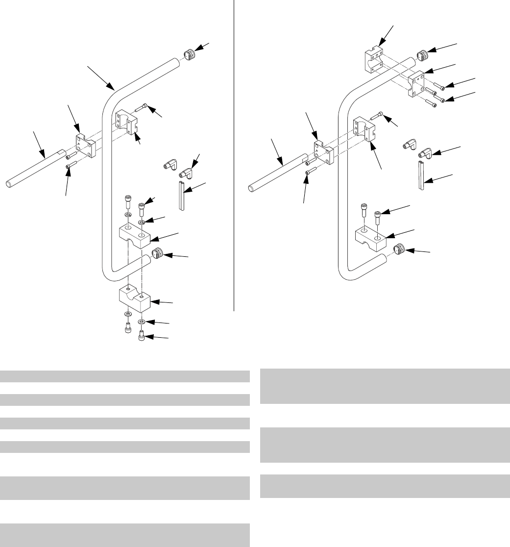
Parts
312760S 65
Applicator Mounting
*Not shown.
/&
808
ti21830a
816
803
801
809
810
803
804
802
805
808 806
807
816
802
817
814
812
811
813
Assemblies with Base Clamp Assemblies with Upper Clamp
809
810
803
804
806
807
816
802
805
808
816
Ref Part Description Qty
801 16P082 BASE, arm, mounting 1
802 16P409 BLOCK, mounting, front 2
803 16P550 BLOCK, mounting, rear 2
804 121194 SCREW 1
805 15K832 ARM, mounting, display 1
806 120913 SCREW 2
807 15M658 CLAMP 1
808 121013 SCREW, socket head cap,
M5-0.8 x 25, mild steel
4
809 121046 TUBE, 1/4 x 1/4 twin, polyure-
thane
6
810 94/0705-1/96 FITTING, elbow, swivel, 1/4
tube x 1/8 npt
2
811 15U176 CLAMP, base (assemblies
256438 and LC0293 only)
1
812 120908 WASHER, plain M8 (assem-
blies 256438 and LC0293
only)
2
813 96/0045/98 WASHER, lock, split, 5/16 in.,
stainless steel (assemblies
256438 and LC0293 only)
2
814 120913 SCREW (assemblies 256438
and LC0293 only)
2
815 * 121003 CABLE, CAN, female / female
3.0 m (assemblies 256438
and LC0293 only)
1
816 126510 PLUG, round, finishing, 7/8 in. 2
817 121273 SCREW, socket head cap, 0.8
x 35, mild steel
2
Ref Part Description Qty
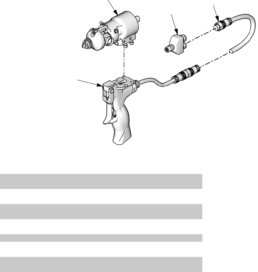
Parts
66 312760S
Dispense Valve
Standard Dispense Valves, 255179 and
255181
See MD2 manual for parts information. See Related
Manuals on page 3.
Gun Mounted MD2 Valves, LC0120 and LC0122
† See MD2 manual for dispense valve and dispense valve handle parts information. See Related Manuals on
page 3.
902
903
901a
901b
ti12440a
Assembly LC0120 Shown
Ref Part Description Qty
901 LC0006 VALVE, assembly, 10:1, gun, electric
(assembly LC0122 only)
1
LC0004 VALVE, assembly, 1:1, gun, electric
(assembly LC0120 only)
1
901a † 255181 VALVE, dispense, 10:1, soft seats
(assembly LC0122 only)
1
† 255179 VALVE, dispense, 1:1, soft seats
(assembly LC0120 only)
1
901b 255208 HANDLE, 2K dispense valve, electric 1
902 121198 CORD, euro, male, 4 pin, 3 wire, 6 m
(Series A Handles only)
1
123660 CORD, euro, male/female, 6 m
(Series B Handles only)
1
903 120953 CONNECTOR, splitter 1
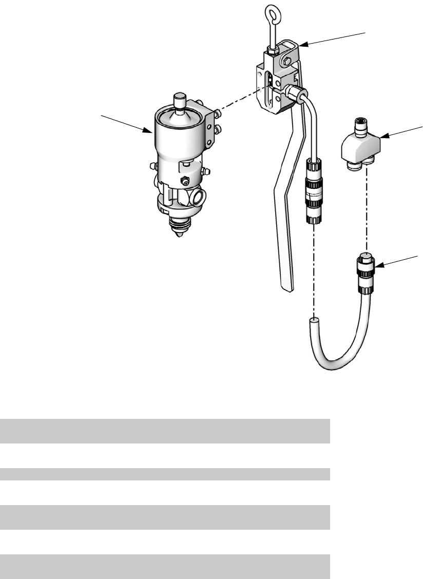
Parts
312760S 67
Lever Actuated MD2 Valves, LC0121 and LC0123
† See MD2 manual for dispense valve and dispense valve lever parts information. See Related Manuals on
page 3.
1101b
1101a
1103
1102
ti12441a
Assembly LC0121 Shown
Ref Part Description Qty
1101 LC0005 VALVE, assembly, 1:1, lever, electric
(assembly LC0121 only)
1
LC0007 VALVE, assembly, 10:1, lever, electric
(assembly LC0123 only)
1
1101a 255249 LEVER, 2K dispense valve 1
1101b † 255181 VALVE, dispense, 10:1, soft seats
(assembly LC0123 only)
1
† 255179 VALVE, dispense, 1:1, soft seats
(assembly LC0121 only)
1
1102 121198 CORD, euro, male, 4 pin, 3 wire, 6 m
(Series A Handles only)
1
123660 CORD, euro, male/female, 6 m
(Series B Handles only)
1
1103 120953 CONNECTOR, splitter 1
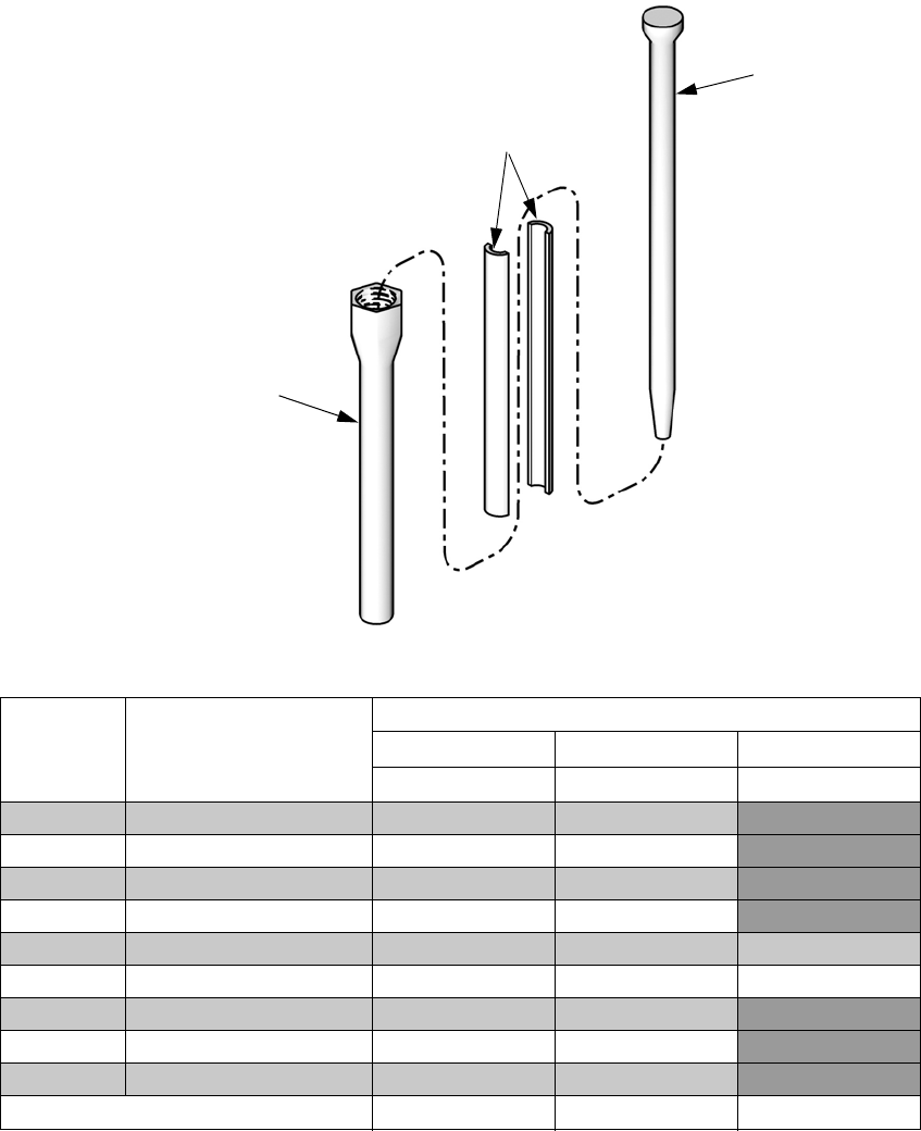
Parts
68 312760S
Mixers
1301
1303
1302
Assembly LC0061 Shown
ti12442a
Mixer
Package Description
Reference Number and Description
1301 1302 1303
Mixer Shroud Sleeve
LC0057 1/4 in. X 24 60/0204/50 94/0883-C/98
LC0058 3/8 in. x 24 60/0200/50 94/0883-D/98
LC0059 3/8 in. x 36 60/0201/50 94/0883-E/98
LC0060 3/8 in. combo 60/0202/50 94/0883-E/98
LC0061 3/16 in. x 32 Luer Lock 60/0212/50 94/0883-L/98 60/0313/97
LC0062 1/4 in. x 24 Luer Lock 60/0209/50 94/0883-M/98 60/0305/97
LC0063 3/16 in. x 32 60/0206/50 94/0884-1/98
LC0295 1/2 in. x 24 60/0111-1/50 94/0885-36/98
LC0296 12 in. x 36 60/0117-1/50 94/0885-24/98
Quantity 10 1 1
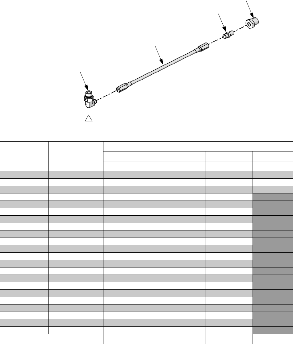
Parts
312760S 69
Hose Packages
Unheated, Non-Recirculating Hoses
1404
1403
1401
1402
Apply thread sealant tape to male npt threads before assembly.
1
Assembly LC0801 Shown
ti12446a
Hose Package Description
Reference Number and Description
1401 1402 1403 1404
Hose Assembly 90 Deg Elbow Adapter Bushing
LC0801 3/16 in. x 30 in. 16C501 94/0144-S/25 94/1000/98 94/0488/98
LC0802 3/16 in. x 120 in. 16C506 94/0144-S/25 94/1000/98 94/0488/98
LC0803 3/16 in. x 180 in. 16C507 94/0144-S/25 94/1000/98 94/0488/98
LC0804 1/4 in. x 30 in. 16C510 94/0148-S/25 J6900040
LC0805 1/4 in. x 120 in. 16C515 94/0148-S/25 J6900040
LC0806 1/4 in. x 180 in. 16C516 94/0148-S/25 J6900040
LC0807 3/8 in. x 30 in. 16C519 94/0149-S/25 94/1007/98
LC0808 3/8 in. x 120 in. 16C524 94/0149-S/25 94/1007/98
LC0809 3/8 in. x 180 in. 16C525 94/0149-S/25 94/1007/98
LC0400 3/8 in. x 30 in. 16D261 94/0149-S/25 94/1007/98
LC401 3/8 in. x 120 in. 16D266 94/0149-S/25 94/1007/98
LC402 3/8 in. x 180 in. 16D267 94/0149-S/25 94/1007/98
LC0810 1/2 in. x 30 in. 16C529 94/0150-S/25 94/1009/98
LC0811 1/2 in. x 120 in. 16C534 94/0150-S/25 94/1009/98
LC0812 1/2 in. x 180 in. 16C535 94/0150-S/25 94/1009/98
LC0403 1/2 in. x 30 in. 16D271 94/0150-S/25 16C399
LC0404 1/2 in. x 120 in. 16D276 94/0150-S/25 16C399
LC0405 1/2 in. x 180 in. 16D277 94/0150-S/25 16C399
LC0813 3/4 in. x 120 in. 16C544 94/0153-S/25 94/1083/98
LC0814 3/4 in. x 180 in. 16C545 94/0153-S/25 94/1083/98
LC0406 3/4 in. x 120 in. 16D286 94/0153-S/25 94/1083/98
LC0407 3/4 in. x 180 in. 16D287 94/0153-S/25 94/1083/98
Quantity 1111
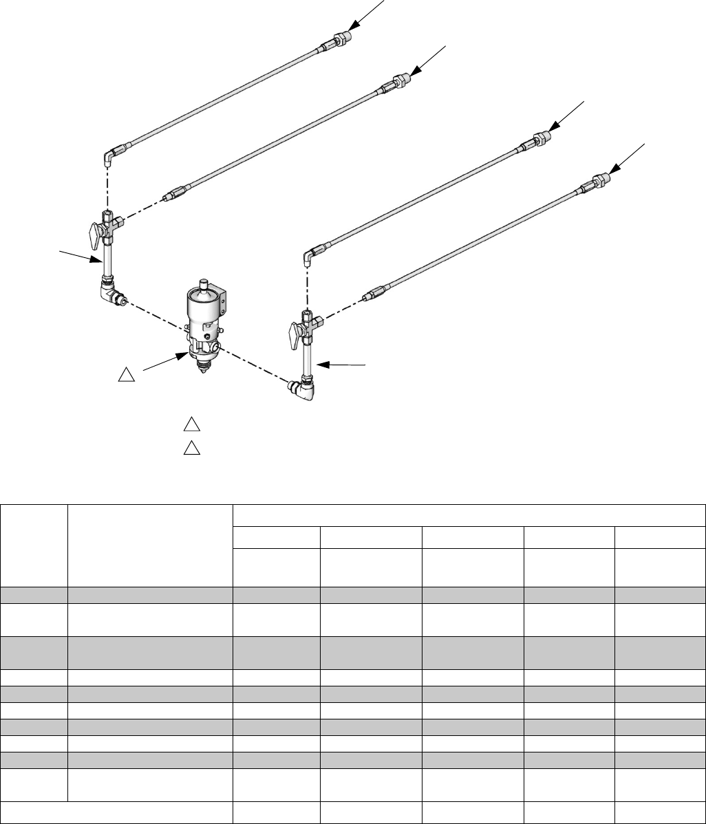
Parts
70 312760S
Unheated, Recirculating Hose Packages
1603
1602
1603
1602
1601
1601
2
Apply thread sealant tape to male npt threads before assembly.
Dispense valve shown for reference only.
1
2
ti12444a
Assembly LC0161 shown installed as the
Low Volume and High Volume Side Hose
Package
Hose
Package Description
Reference Number and Description
1601 1602 1603 1604 1605
Valve
Assembly
Supply Hose
Assembly
Return Hose
Assembly
Pressure
Sensor O-Ring
LC0161 3/16 in. x 30 in., on-board 255977 255983 255997 16A093 111457
LC0162 3/16 in. x 120 in.,
on-board
255977 255984 255998 16A093 111457
LC0163 3/16 in. x 180 in.,
on-board
255977 255985 255999 16A093 111457
LC0164 1/4 in. x 30 in., on-board 255976 255986 258058 16A093 111457
LC0165 1/4 in. x 120 in., on-board 255976 255987 258059 16A093 111457
LC0166 1/4 in. x 180 in., on-board 255976 255988 258060 16A093 111457
LC0167 3/8 in. x 30 in., on-board 255975 255989 258061 16A093 111457
LC0168 3/8 in. x 120 in., on-board 255975 255990 258062 16A093 111457
LC0169 3/8 in. x 180 in., on-board 255975 255991 258063 16A093 111457
LC0432 3/8 in. x 30 in., on-board,
high pressure
255975 LC0408 LC0416 16A093 111457
Quantity 11 1 11

Parts
312760S 71
LC0433 3/8 in. x 120 in., on-board,
high pressure
255975 LC0409 LC0417 16A093 111457
LC0434 3/8 in. x 180 in., on-board,
high pressure
255975 LC0410 LC0418 16A093 111457
LC0170 1/2 in. x 30 in., on-board 255974 255992 258064 16A093 111457
LC0171 1/2 in. x 120 in., on-board 255974 255993 258065 16A093 111457
LC0172 1/2 in. x 180 in., on-board 255974 255994 258066 16A093 111457
LC0435 1/2 in. x 30 in., on-board,
high pressure
255974 LC0411 LC0419 16A093 111457
LC0436 1/2 in. x 120 in., on-board,
high pressure
255974 LC0412 LC0420 16A093 111457
LC0437 1/2 in. x 180 in., on-board,
high pressure
255974 LC0413 LC0421 16A093 111457
LC0173 3/4 in. x 120 in., on-board 255974 255995 258067 16A093 111457
LC0174 3/4 in. x 180 in., on-board 255974 255996 258068 16A093 111457
LC0438 3/4 in. x 120 in., on-board,
high pressure
255974 LC0414 LC0422 16A093 111457
LC0439 3/4 in. x 180 in., on-board,
high pressure
255974 LC0415 LC0423 16A093 111457
LC0175 3/16 in. x 30 in., off-board 255977 255983 258069 16A093 111457
LC0176 3/16 in. x 120 in.,
off-board
255977 255984 258070 16A093 111457
LC0177 3/16 in. x 180 in.,
off-board
255977 255985 258071 16A093 111457
LC0178 1/4 in. x 30 in., off-board 255976 255986 258072 16A093 111457
LC0179 1/4 in. x 120 in., off-board 255976 255987 258073 16A093 111457
LC0180 1/4 in. x 180 in., off-board 255976 255988 258074 16A093 111457
LC0181 3/8 in. x 30 in., off-board 255975 255989 258075 16A093 111457
LC0182 3/8 in. x 120 in., off-board 255975 255990 258076 16A093 111457
LC0183 3/8 in. x 180 in., off-board 255975 255991 258077 16A093 111457
LC0440 3/8 in. x 30 in., off-board,
high pressure
255975 LC0408 LC0424 16A093 111457
LC0441 3/8 in. x 120 in., off-board,
high pressure
255975 LC0409 LC0425 16A093 111457
LC0442 3/8 in. x 180 in., off-board,
high pressure
255975 LC0410 LC0426 16A093 111457
LC0184 1/2 in. x 30 in., off-board 255974 255992 258078 16A093 111457
LC0185 1/2 in. x 120 in., off-board 255974 255993 258079 16A093 111457
LC0186 1/2 in. x 180 in., off-board 255974 255994 258080 16A093 111457
LC0443 1/2 in. x 30 in., off-board,
high pressure
255974 LC0411 LC0427 16A093 111457
LC0444 1/2 in. x 120 in., off-board,
high pressure
255974 LC0412 LC0428 16A093 111457
Hose
Package Description
Reference Number and Description
1601 1602 1603 1604 1605
Valve
Assembly
Supply Hose
Assembly
Return Hose
Assembly
Pressure
Sensor O-Ring
Quantity 11 1 11

Parts
72 312760S
LC0445 1/2 in. x 180 in., off-board,
high pressure
255974 LC0413 LC0429 16A093 111457
LC0187 3/4 in. x 120 in., off-board 255974 255995 258081 16A093 111457
LC0188 3/4 in. x 180 in., off-board 255974 255996 258082 16A093 111457
LC0446 3/4 in. x 120 in., off-board,
high pressure
255974 LC0414 LC0430 16A093 111457
LC0447 3/4 in. x 180 in., off-board,
high pressure
255974 LC4015 LC0431 16A093 111457
Hose
Package Description
Reference Number and Description
1601 1602 1603 1604 1605
Valve
Assembly
Supply Hose
Assembly
Return Hose
Assembly
Pressure
Sensor O-Ring
Quantity 11 1 11
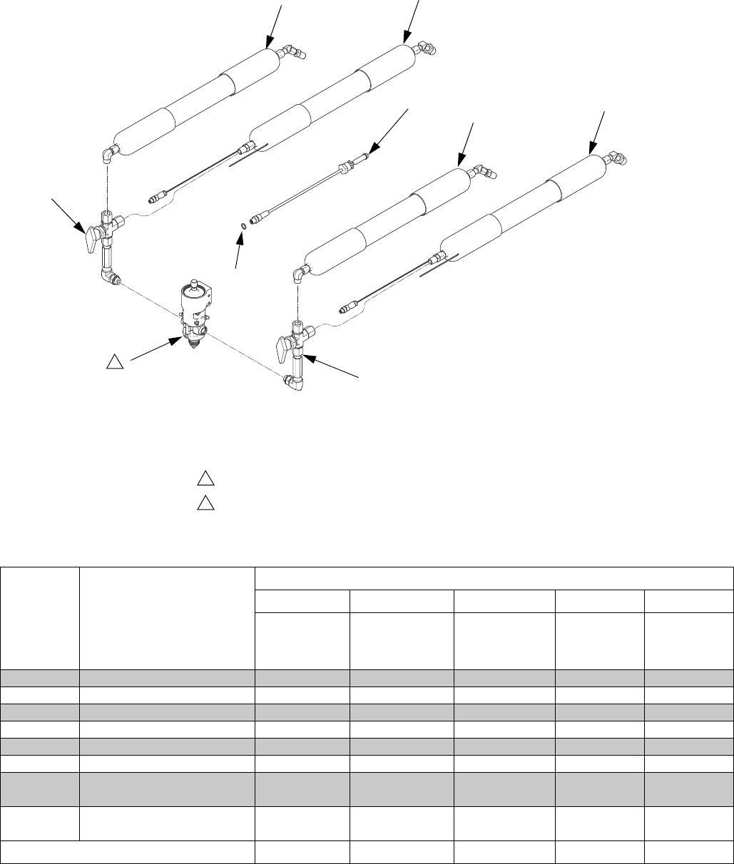
Parts
312760S 73
Heated, Recirculating Hose Packages
1703 1702
1703 1702
1701
1701
2
Apply thread sealant tape to male npt threads before assembly.
Dispense valve shown for reference only.
1
2
Assembly LC0190 shown installed as
the Low Volume and High Volume
Side Hose Package
ti12443b
1704
1705
Hose
Package Description
Reference Number and Description
1701 1702 1703 1704 1705
Valve
Assembly
Heated
Supply Hose
Assembly
Insulated
Return Hose
Assembly
Pressure
Sensor O-Ring
LC0190 1/4 in. x 30 in., on-board 255976 258084 258095 16A093 111457
LC0191 1/4 in. x 120 in., on-board 255976 258085 258096 16A093 111457
LC0192 1/4 in. x 180 in., on-board 255976 258086 258097 16A093 111457
LC0193 3/8 in. x 30 in., on-board 255975 258087 258098 16A093 111457
LC0194 3/8 in. x 120 in., on-board 255975 258088 258099 16A093 111457
LC0195 3/8 in. x 180 in., on-board 255975 258089 258121 16A093 111457
LC0472 3/8 in. x 30 in., on-board,
high pressure
255975 258087 LC0456 16A093 111457
LC0473 3/8 in. x 120 in., on-board,
high pressure
255975 258088 LC0457 16A093 111457
Quantity 11 111

Parts
74 312760S
LC0474 3/8 in. x 180 in., on-board,
high pressure
255975 258089 LC0458 16A093 111457
LC0196 1/2 in. x 30 in., on-board 255974 258090 258122 16A093 111457
LC0197 1/2 in. x 120 in., on-board 255974 258091 258123 16A093 111457
LC0198 1/2 in. x 180 in., on-board 255974 258092 258124 16A093 111457
LC0475 1/2 in. x 30 in., on-board,
high pressure
255974 258090 LC0459 16A093 111457
LC0476 1/2 in. x 120 in., on-board,
high pressure
255974 258091 LC0460 16A093 111457
LC0477 1/2 in. x 180 in., on-board,
high pressure
255974 258092 LC0461 16A093 111457
LC0199 3/4 in. x 120 in., on-board 255974 258093 258125 16A093 111457
LC0200 3/4 in. x 180 in., on-board 255974 258094 258126 16A093 111457
LC0478 3/4 in. x 120 in., on-board,
high pressure
255974 258093 LC0462 16A093 111457
LC0479 3/4 in. x 180 in., on-board,
high pressure
255974 258094 LC0463 16A093 111457
LC0201 1/4 in. x 30 in., off-board 255976 258084 258127 16A093 111457
LC0202 1/4 in. x 120 in., off-board 255976 258085 258128 16A093 111457
LC0203 1/4 in. x 180 in., off-board 255976 258086 258129 16A093 111457
LC0204 3/8 in. x 30 in., off-board 255975 258087 258130 16A093 111457
LC0205 3/8 in. x 120 in., off-board 255975 258088 258131 16A093 111457
LC0206 3/8 in. x 180 in., off-board 255975 258089 258132 16A093 111457
LC0480 3/8 in. x 30 in., off-board,
high pressure
255975 258087 LC0464 16A093 111457
LC0481 3/8 in. x 120 in., off-board,
high pressure
255975 258088 LC0465 16A093 111457
LC0482 3/8 in. x 180 in., off-board,
high pressure
255975 258089 LC0466 16A093 111457
LC0207 1/2 in. x 30 in., off-board 255974 258090 258133 16A093 111457
LC0208 1/2 in. x 120 in., off-board 255974 258091 258134 16A093 111457
LC0209 1/2 in. x 180 in., off-board 255974 258092 258135 16A093 111457
LC0483 1/2 in. x 30 in., off-board,
high pressure
255974 258090 LC0467 16A093 111457
LC0484 1/2 in. x 120 in., off-board,
high pressure
255974 258091 LC0468 16A093 111457
LC0485 1/2 in. x 180 in., off-board,
high pressure
255974 258092 LC0469 16A093 111457
LC0210 3/4 in. x 120 in., off-board 255974 258093 258136 16A093 111457
LC0211 3/4 in. x 180 in., off-board 255974 258094 258137 16A093 111457
LC0486 3/4 in. x 120 in., off-board,
high pressure
255974 258093 LC0470 16A093 111457
LC0487 3/4 in. x 180 in., off-board,
high pressure
255974 258094 LC0471 16A093 111457
Hose
Package Description
Reference Number and Description
1701 1702 1703 1704 1705
Valve
Assembly
Heated
Supply Hose
Assembly
Insulated
Return Hose
Assembly
Pressure
Sensor O-Ring
Quantity 11 111
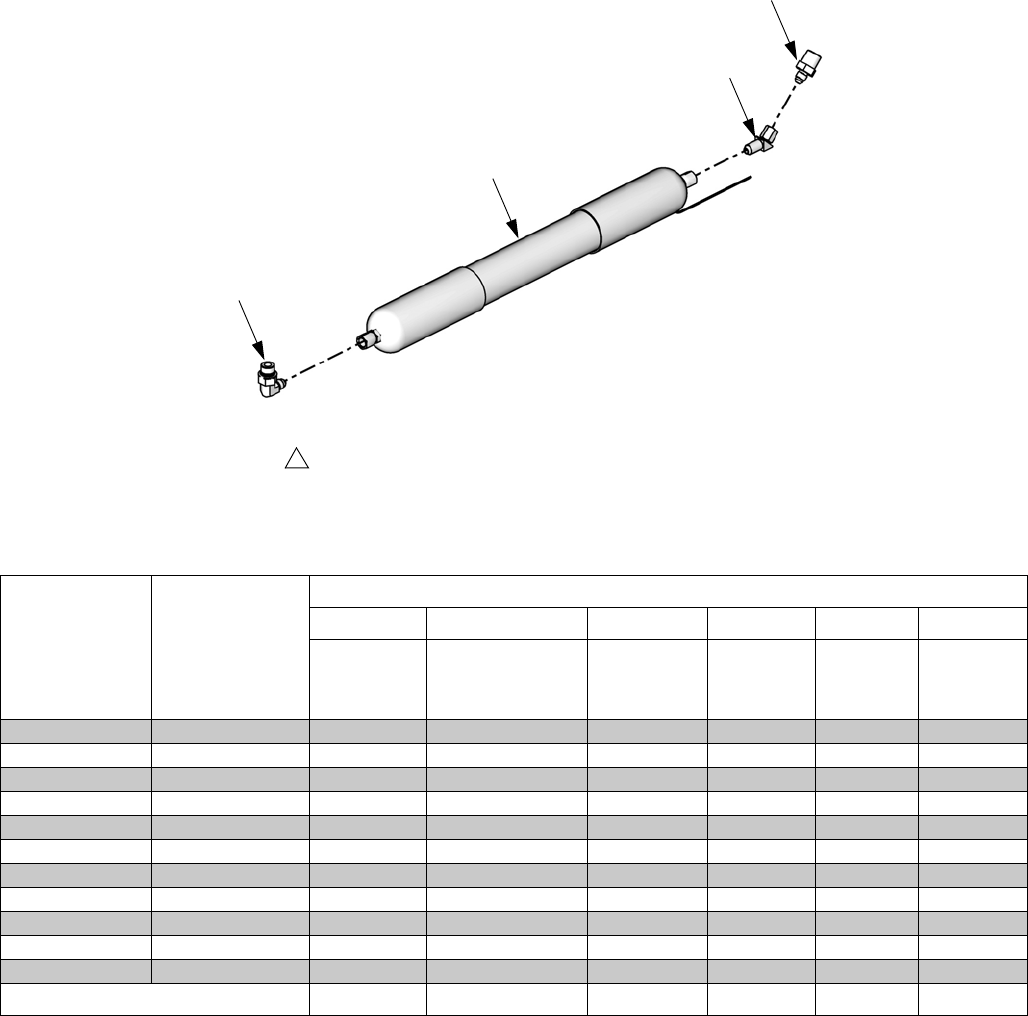
Parts
312760S 75
Heated, Non-Recirculating Hoses
*Not shown.
Hose Package Description
Reference Number and Description
1501 1502 1503 1504 * 1505 * 1506
Heated
Hose
Assembly
90 Degree
Elbow Adapter
45 Degree
Elbow
Circuit
Breaker
Extension
Cord
LC0881 1/4 in. x 30 in. 16C554 94/0148-S/25 J6900040 121041 121630 121683
LC0882 1/4 in. x 120 in. 16C558 94/0148-S/25 J6900040 121041 121632 121683
LC0883 1/4 in. x 180 in. 16C559 94/0148-S/25 J6900040 121041 121633 121683
LC0884 3/8 in. x 30 in. 16C562 94/0149-S/25 94/1007/98 121042 121630 121683
LC0885 3/8 in. x 120 in. 16C566 94/0149-S/25 94/1007/98 121042 121632 121683
LC0886 3/8 in. x 180 in. 16C567 94/0149-S/25 94/1007/98 121042 16E546 121683
LC0887 1/2 in. x 30 in. 16C570 94/0150-S/25 16C399 121043 121630 121683
LC0888 1/2 in. x 120 in. 16C574 94/0150-S/25 16C399 121043 121632 121683
LC0889 1/2 in. x 180 in. 16C575 94/0150-S/25 16C399 121043 16E546 121683
LC0890 3/4 in. x 120 in. 16C582 94/0153-S/25 94/0103/98 121044 121632 121683
LC0891 3/4 in. x 180 in. 16C583 94/0153-S/25 94/0103/98 121044 16E546 121683
Quantity 111111
1503
1504
1501
1502
Apply thread sealant tape to male npt threads before assembly.
1
Part LC0881 Shown
ti12445a
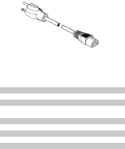
Parts
76 312760S
Power Cords
Power
Cord
Package Description
121054 CORD SET, 250V, 10A, United States
121055 CORD SET, 250V, 10A, North America
121056 CORD SET, 250V, 10A, Continental Europe
121057 CORD SET, 250V, 10A, United Kingdom/Ire-
land
121058 CORD SET, 250V, 10A, Israel
121060 CORD SET, 250V, 10A, India
124861 CORD SET, 250V, 10A, Italy
124862 CORD SET, 250V, 10A, Denmark
124863 CORD SET, 250V, 10A, Switzerland
124864 CORD SET, 250V, 10A, Australia
Part 121054 Shown
ti12447a
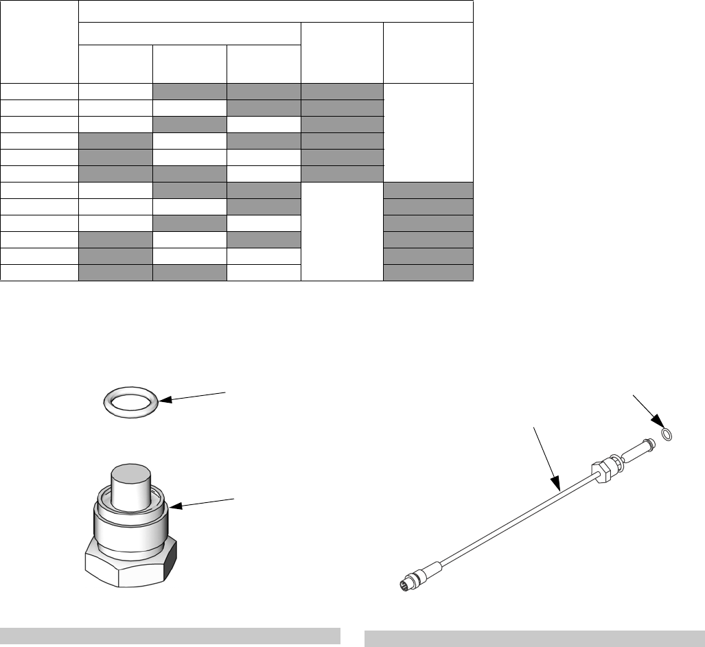
Parts
312760S 77
Flow Monitoring
Pump Plug, Assembly LC0041
Pressure Transducer, Assembly 257433
Flow
Monitoring
Package
Part Number and Quantity
Flow Meters Pressure
Transducer,
257433
Pump Plug,
LC0041
0.5 gpm,
LC0299
1.0 gpm,
LC0300
2.0 gpm,
LC0301
LC0302 2
1
LC0303 1 1
LC0304 1 1
LC0305 2
LC0306 11
LC0307 2
LC0312 2
1
LC0313 1 1
LC0314 1 1
LC0315 2
LC0316 11
LC0317 2
Ref Part Description Qty
1801 15K815 PLUG, dummy, transducer 2
1802 111457 PACKING, o-ring 2
1802
1801
ti12448a
Ref Part Description Qty
1901 16A093 SENSOR, pressure 2
1902 111457 O-RING 2
ti13391b
1902
1901
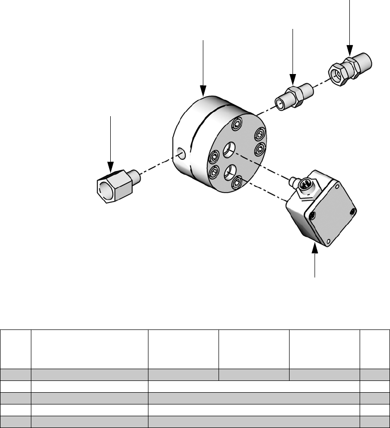
Parts
78 312760S
Flow Meters
Ref Description
0.5 gpm Flow
Meter Assy,
LC0299
1.0 gpm Flow
Meter Assy,
LC0300
2.0 gpm Flow
Meter Assy,
LC0301 Qty
2001 METER, flow 121932 121933 121934 1
2002 SENSOR, meter, flow 121909 1
2003 ADAPTER, reducer 94/0745/98 1
2004 FITTING, nipple, hex 121907 1
2005 FITTING, adapter 121908 1
2002
2001
2004
2005
2003
ti13390a
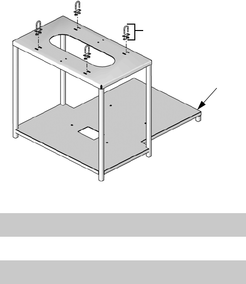
Parts
312760S 79
Tank Stands, Assemblies
LC0247 and LC0103
Heat Zone Assemblies
See Integrated Heat manual referenced at the beginning
of this manual for Heat Zone Assemblies parts informa-
tion.
Ref Part Description Qty
2001 121097 FASTENER, u-bolt with mounting
plate
4
2002 15U373 SUPPORT, tank stand, variable
ratio (assembly LC0247 only)
1
15M478 SUPPORT, off-board tank stand
(assembly LC0103 only)
1
2002
2001
Assembly LC0247 Shown
ti12473a

Kits
80 312760S
Kits
Mixer and Shroud Options
MD2 Valve Kits
Machine Rebuild Kits
Tank Accessories
† Item includes only the pump. A vacuum kit must be pur-
chased to install the pump onto the tank.
Kit includes all parts needed to connect a nitrogen tank
to the material tank.
Part Description
LC0063 Mixer, 3/16 in. (6.5 mm) x 32, 10 Mixers
with shroud
LC0057 Mixer, 1/4 in. (6.5 mm) x 24, 10 Mixers
with shroud
LC0058 Mixer, 3/8 in. (9.8 mm) x 24, 10 Mixers
with shroud
LC0059 Mixer, 3/8 in. (9.8 mm) x 36, 10 Mixers
with shroud
LC0060 Mixer, 3/8 in. (9.8 mm) Combo, 10 Mixers
with shroud
LC0061 Mixer, 3/16 in. (4.8 mm) x 32 Luer Lock, 10
Mixers with shroud
LC0062 Mixer, 1/4 in. (6.5 mm) x 24 Luer Lock, 10
Mixers with shroud
LC0077 Mixer, 3/16 in. (4.8 mm) x 32, 50 Mixers
LC0078 Mixer, 1/4 in. (6.5 mm) x 24, 50 Mixers
LC0079 Mixer, 3/8 in. (9.8 mm) x 24, 50 Mixers
LC0080 Mixer, 3/8 in. (9.8 mm) x 36, 50 Mixers
LC0081 Mixer, 3/8 in. (9.8 mm) combo, 50 Mixers
LC0083 Mixer, 1/4 in. (6.5 mm) x 24 Luer Lock, 50
Mixers
LC0082 Mixer, 3/16 in. (4.8 mm) x 32 Luer Lock, 50
Mixers
LC0084 Mixer, 3/16 in. (4.8 mm) x 32, 250 Mixers
LC0085 Mixer, 1/4 in. (6.5 mm) x 24, 250 Mixers
LC0086 Mixer, 3/8 in. (9.8 mm) x 24, 250 Mixers
LC0087 Mixer, 3/8 in. (9.8 mm) x 36, 250 Mixers
LC0088 Mixer, 3/8 in. (9.8 mm) combo, 250 Mixers
LC0089 Mixer, 3/16 in. (4.8 mm) x 32 Luer Lock,
250 Mixers
LC0090 Mixer, 1/4 in. (6.5 mm) x 24 Luer Lock, 250
Mixers
See MD2 Dispense Valve instruction manual refer-
enced at the beginning of this manual for installa-
tion instructions or for more information.
Part Description
255217 MD2, kit rebuild, air cylinder
255218 MD2, kit rebuild, back-end of wet section
(no needle or seat)
255219 MD2, Soft Seat rebuild, needle and nose
255220 MD2, convert Soft Seat nose to Hard Seat
(Hard Seat rebuild), needle and nose
Part Description
LC0091 3.0 in. Air Cylinder rebuild kit
LC0092 4.5 in. Air Cylinder rebuild kit
LC0093 Check Valve rebuild kit, Stainless Steel Ball
LC0318 Check Valve rebuild kit, Carbide Ball
LC0094 Rear Pump Seal rebuild kit
Part Description
LC0097 Desiccant Dryer, 3/8 in. NPT with adapter
and cartridge
LC0098 Desiccant Dryer refill cartridge
LC0095 Nitrogen Harness Kit for 30 L and 60 L
tank, 1 tank
LC0096 Nitrogen Harness Kit for 30 L and 60 L
tank, 2 tanks
†LC0099 Vacuum Transfer Pump, 120V, down to 25
To rr
†LC0100 Vacuum Transfer Pump, 240V, down to 25
To rr
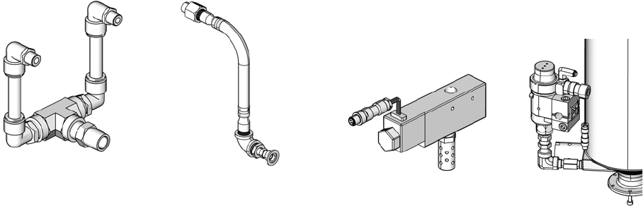
Kits
312760S 81
Vacuum Kits
These vacuum kits contain the parts necessary to
attach a vacuum pump to the tanks.
Refill Kits
Refill Kits 256659 and 256660 are designed to turn on
and off a transfer pump as needed to keep the tanks at
the proper fluid level. Tank Refill Kit 256577 is designed
to open and close a valve to allow fluid to flow into the
tank from an always-on transfer pump. Tank Refill
Kit 256577 includes the parts necessary to install on the
base or lid of a 7.5 L, 30 L, or 60 L tank.
External Control Interface Connection Kit
Part Description
256205 Vacuum Kit, Single On-Board Tank
256206 Vacuum Kit, Two On-Board Tanks
256207 Vacuum Kit, Single Off-Board Tank
256208 Vacuum Kit, Two Off-Board Tanks
Assembly 256206
Shown
Assembly 256207
Shown
On-Board
Vacuum Kits
Off-Board
Vacuum Kits
ti12588a ti12589a
Part Description
256659 Refill Kit, 1/4 npt, solenoid, 24V
256660 Refill Kit, 1/2 npt, solenoid, 24V
256577 Tank Refill Kit
Part Description
LC0008 Cord, I/O interface and splitter
Assembly 256659
Shown
Assembly 256577 shown
installed on tank for reference
ti12590a
ti12591a
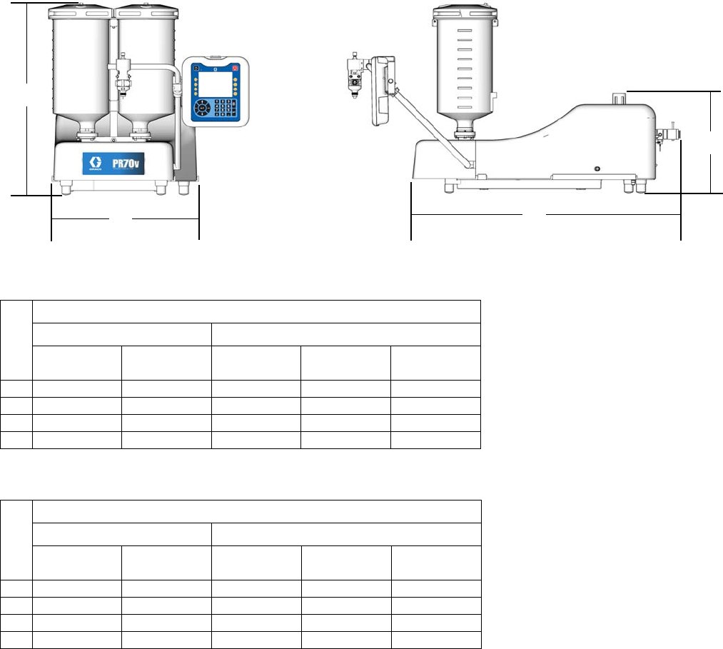
Dimensions
82 312760S
Dimensions
Machine with On-Board Tanks
PR70
PR70v
† Assembly dimensions listed are maximum for all assemblies under the given title.
On-board stainless steel tank dimensions include ball valves and vacuum de-gas in maximum height calculation.
B
A
C
D
ti12621b ti12622b
Ref
† Assembly Dimensions, in. (mm)
Polyethylene Tanks Stainless Steel Tanks
No Agitators With Agitators 3 L 7.5 L, No
Agitators
7.5 L, with
Agitators
A 26.4 (670) 38.6 (980) 28.2 (716) 38.2 (970) 39.9 (1013)
B 18.5 (470) 18.5 (470) 15.5 (394) 15.5 (394) 15.5 (394)
C 30.6 (778) 30.6 (778) 30.6 (778) 30.6 (778) 30.6 (778)
D 13.4 (340) 13.4 (340) 13.4 (340) 13.4 (340) 13.4 (340)
Ref
† Assembly Dimensions, in. (mm)
Polyethylene Tanks Stainless Steel Tanks
No Agitators With Agitators 3L, No
Agitators
7.5 L, No
Agitators
7.5 L, with
Agitators
A 30.0 (762) 39.4 (1001) 29.0 (737) 39.0 (991) 40.6 (1031)
B 20.9 (531) 20.9 (531) 20.9 (531) 20.9 (531) 20.9 (531)
C 38.6 (980) 38.6 (980) 38.6 (980) 38.6 (980) 38.6 (980)
D 14.3 (363) 14.3 (363) 14.3 (363) 14.3 (363) 14.3 (363)
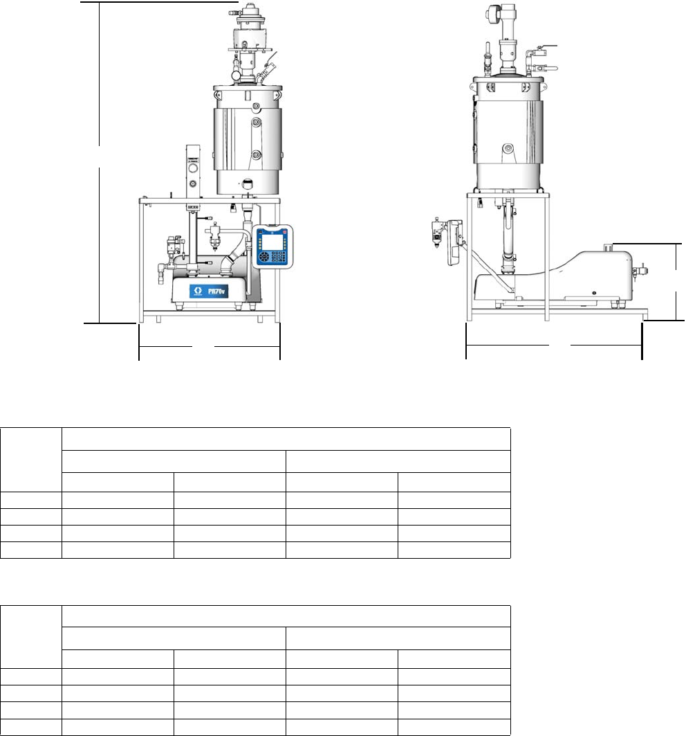
Machine with Off-Board Tanks
PR70
PR70v
† Assembly dimensions listed are maximum for all assemblies under the given title.
Ref
† Assembly Dimensions, in. (mm)
30 L Tank 60 L Tank
No Agitators With Agitators No Agitators With Agitators
A 75.7 (1923) 83.4 (2118) 64.9 (1648) 89.5 (2273)
B 32.1 (815) 32.1 (815) 32.1 (815) 32.1 (815)
C 29.3 (236) 29.3 (236) 29.3 (236) 29.3 (236)
D 16.0 (406) 16.0 (406) 16.0 (406) 16.0 (406)
Ref
† Assembly Dimensions, in. (mm)
30 L Tank 60 L Tank
No Agitators With Agitators No Agitators With Agitators
A 75.7 (1923) 83.4 (2118) 64.9 (1648) 89.5 (2273)
B 32.1 (815) 32.1 (815) 32.1 (815) 32.1 (815)
C 40.1 (1019) 40.1 (1019) 40.1 (1019) 40.1 (1019)
D 17.0 (432) 17.0 (432) 17.0 (432) 17.0 (432)
C
B
A
D
ti12623c ti12624c
Technical Data
84 312760S
Technical Data
Metering Pump Effective Area . . . . . . . . . . . . . . . . . . . . . 80 to 960 mm2 (0.124 to 1.49 in.2) per side
Small Air Cylinder Effective Area . . . . . . . . . . . . . . . . . . 4560 mm2 (7.07 in.2)
Large Air Cylinder Effective Area . . . . . . . . . . . . . . . . . . 10260 mm2 (15.9 in.2)
Maximum Stroke Length . . . . . . . . . . . . . . . . . . . . . . . . . 38.1 mm (1.50 in.)
Minimum Stroke Length . . . . . . . . . . . . . . . . . . . . . . . . . 5.8 mm (0.23 in.)
Volume per Cycle . . . . . . . . . . . . . . . . . . . . . . . . . . . . . . 2 to 70 cc (0.12 to 4.3 in.3)
Pump Cycles per 1 L (0.26 gal) . . . . . . . . . . . . . . . . . . . . 14.3 to 500 cycles (varies by piston size)
Ratios (fixed) . . . . . . . . . . . . . . . . . . . . . . . . . . . . . . . . . . 1:1 to 12:1 (depending upon cylinders selected)
Maximum Fluid Working Pressure . . . . . . . . . . . . . . . . . 3000 psi (20.7 MPa, 207 bar)
Maximum Air Input Pressure . . . . . . . . . . . . . . . . . . . . . . 100 psi (0.7 MPa, 7 bar)
Maximum Cycle Rate . . . . . . . . . . . . . . . . . . . . . . . . . . . 30 cycles per minute
Maximum Operating Temperature . . . . . . . . . . . . . . . . . . 70°C (160°F), nylon pistons 50°C (120°F) UHMWPE pis-
tons or PE Tanks
Air Inlet Size . . . . . . . . . . . . . . . . . . . . . . . . . . . . . . . . . . 1/4 NPT female
Pump Fluid Outlet Size . . . . . . . . . . . . . . . . . . . . . . . . . . -03, -04, -06, -08 or –12 JIC fittings for 3/16 in. (4.8 mm),
1/4 in. (6.4 mm), 3/8 in. (9.5 mm), 1/2 in. (12.7 mm),
3/4 in. (19.1 mm) hoses
Wetted Parts . . . . . . . . . . . . . . . . . . . . . . . . . . . . . . . . . . 303/304, 17-4 PH, hard chrome, Chromex™, carbide,
Chemical Resistant O-rings, PTFE, nylon, UHMWPE
Weight . . . . . . . . . . . . . . . . . . . . . . . . . . . . . . . . . . . . . . . 55 kg (120 lb) typical with two 7.5 L tanks
150 kg (330 lb) typical with two 60 L tanks
Sound Pressure Level (at typical operator station for
machine mounted Dispense Valve) . . . . . . . . . . . . . . . . . 82 dBA
Compressed Air . . . . . . . . . . . . . . . . . . . . . . . . . . . . . . . Less than 10 scfm typical (varies with cycle times)
Electrical Power . . . . . . . . . . . . . . . . . . . . . . . . . . . . . . . . • 100-240V 50/60Hz, 1 phase for machine – 80 Watts
• 208-240V 50/60Hz, 1 phase for heat – 11 kW max
• 120 or 240 VAC 50/60Hz 1 phase for on-board agita-
tors, 80 Watts
• 240 VAC 50/60Hz 1 phase for off-board agitators,
600 Watts

Technical Data
312760S 85

Graco Standard Warranty
Graco warrants all equipment referenced in this document which is manufactured by Graco and bearing its name to be free from defects in
material and workmanship on the date of sale to the original purchaser for use. With the exception of any special, extended, or limited warranty
published by Graco, Graco will, for a period of twelve months from the date of sale, repair or replace any part of the equipment determined by
Graco to be defective. This warranty applies only when the equipment is installed, operated and maintained in accordance with Graco’s written
recommendations.
This warranty does not cover, and Graco shall not be liable for general wear and tear, or any malfunction, damage or wear caused by faulty
installation, misapplication, abrasion, corrosion, inadequate or improper maintenance, negligence, accident, tampering, or substitution of
non-Graco component parts. Nor shall Graco be liable for malfunction, damage or wear caused by the incompatibility of Graco equipment with
structures, accessories, equipment or materials not supplied by Graco, or the improper design, manufacture, installation, operation or
maintenance of structures, accessories, equipment or materials not supplied by Graco.
This warranty is conditioned upon the prepaid return of the equipment claimed to be defective to an authorized Graco distributor for verification of
the claimed defect. If the claimed defect is verified, Graco will repair or replace free of charge any defective parts. The equipment will be returned
to the original purchaser transportation prepaid. If inspection of the equipment does not disclose any defect in material or workmanship, repairs will
be made at a reasonable charge, which charges may include the costs of parts, labor, and transportation.
THIS WARRANTY IS EXCLUSIVE, AND IS IN LIEU OF ANY OTHER WARRANTIES, EXPRESS OR IMPLIED, INCLUDING BUT NOT LIMITED
TO WARRANTY OF MERCHANTABILITY OR WARRANTY OF FITNESS FOR A PARTICULAR PURPOSE.
Graco’s sole obligation and buyer’s sole remedy for any breach of warranty shall be as set forth above. The buyer agrees that no other remedy
(including, but not limited to, incidental or consequential damages for lost profits, lost sales, injury to person or property, or any other incidental or
consequential loss) shall be available. Any action for breach of warranty must be brought within two (2) years of the date of sale.
GRACO MAKES NO WARRANTY, AND DISCLAIMS ALL IMPLIED WARRANTIES OF MERCHANTABILITY AND FITNESS FOR A
PARTICULAR PURPOSE, IN CONNECTION WITH ACCESSORIES, EQUIPMENT, MATERIALS OR COMPONENTS SOLD BUT NOT
MANUFACTURED BY GRACO. These items sold, but not manufactured by Graco (such as electric motors, switches, hose, etc.), are subject to
the warranty, if any, of their manufacturer. Graco will provide purchaser with reasonable assistance in making any claim for breach of these
warranties.
In no event will Graco be liable for indirect, incidental, special or consequential damages resulting from Graco supplying equipment hereunder, or
the furnishing, performance, or use of any products or other goods sold hereto, whether due to a breach of contract, breach of warranty, the
negligence of Graco, or otherwise.
FOR GRACO CANADA CUSTOMERS
The Parties acknowledge that they have required that the present document, as well as all documents, notices and legal proceedings entered into,
given or instituted pursuant hereto or relating directly or indirectly hereto, be drawn up in English. Les parties reconnaissent avoir convenu que la
rédaction du présente document sera en Anglais, ainsi que tous documents, avis et procédures judiciaires exécutés, donnés ou intentés, à la suite
de ou en rapport, directement ou indirectement, avec les procédures concernées.
Graco Information
For the latest information about Graco products, visit www.graco.com.
TO PLACE AN ORDER, contact your Graco distributor or call to identify the nearest distributor.
Toll Free: 1-800-746-1334 or Fax: 330-966-3006.
All written and visual data contained in this document reflects the latest product information available at the time of publication.
Graco reserves the right to make changes at any time without notice.
For patent information, see www.graco.com/patents.
Original instructions. This manual contains English. MM 312760
Graco Headquarters: Minneapolis
International Offices: Belgium, China, Japan, Korea
GRACO INC. AND SUBSIDIARIES • P.O. BOX 1441 • MINNEAPOLIS MN 55440-1441 • USA
Copyright 2008, Graco Inc. All Graco manufacturing locations are registered to ISO 9001.
www.graco.com
Revised February 2014
