Graco 313435T 1050 Air Operated Diaphragm Pump Users Manual 313435T, Pump, Repair/Parts, English
2015-04-02
: Graco Graco-313435T-1050-Air-Operated-Diaphragm-Pump-Users-Manual-686293 graco-313435t-1050-air-operated-diaphragm-pump-users-manual-686293 graco pdf
Open the PDF directly: View PDF ![]() .
.
Page Count: 34
Repair/Parts
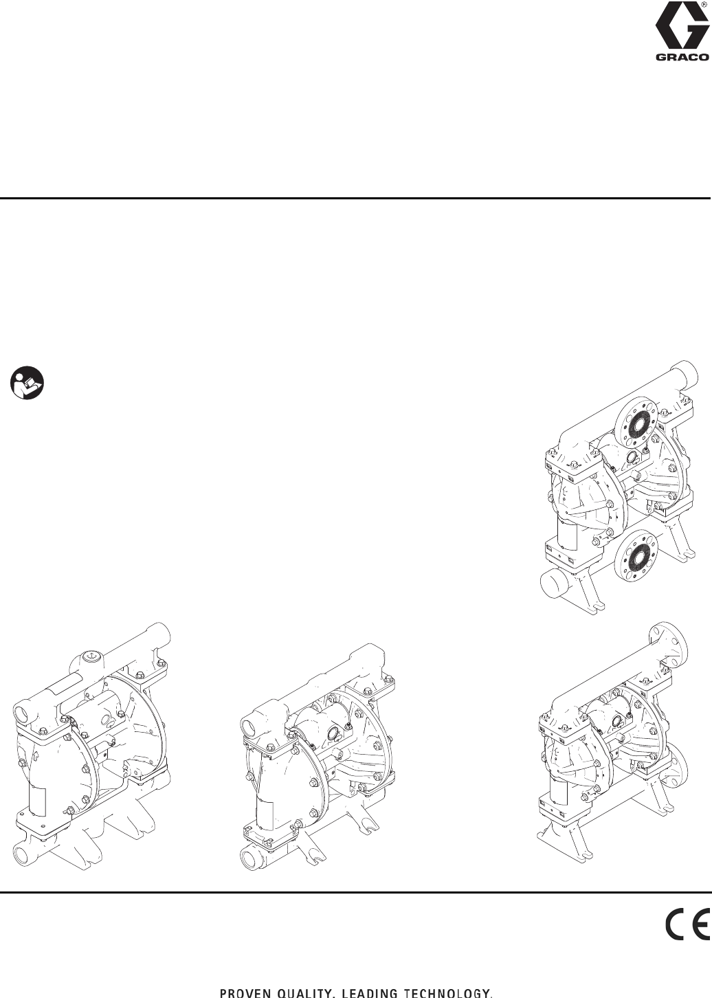
Husky® 1050 Air-Operated
Diaphragm Pump 313435T
EN
1-inch pump with modular air valve for fluid transfer applications.
For professional use only.
See page 4 for model information, including approvals.
125 psi (0.86 MPa, 8.6 bar) Maximum Fluid Working Pressure
125 psi (0.86 MPa, 8.6 bar) Maximum Air Input Pressure
Center
Flange
ti13844a
ti13843a
End
Flange
1050P Polypropylene
1050C Conductive
Polypropylene
1050F PVDF
Important Safety Instructions
Read all warnings and instructions in this manual.
Save these instructions.
1050S Stainless Steel
1050H Hastelloy
ti14342a
1050A Aluminum
ti13946a

Related Manuals
2313435T
Contents
Related Manuals . . . . . . . . . . . . . . . . . . . . . . . . . . . 2
To Find Your Nearest Distributor . . . . . . . . . . . . . . 3
To Specify the Configuration of a New Pump . . . . 3
To Order Replacement Parts . . . . . . . . . . . . . . . . . 3
Distributor Note . . . . . . . . . . . . . . . . . . . . . . . . . . . . 3
Pump Matrix . . . . . . . . . . . . . . . . . . . . . . . . . . . . . . . 4
ATEX Certifications . . . . . . . . . . . . . . . . . . . . . . . . . 5
Warnings . . . . . . . . . . . . . . . . . . . . . . . . . . . . . . . . . 5
Troubleshooting . . . . . . . . . . . . . . . . . . . . . . . . . . . . 8
Repair . . . . . . . . . . . . . . . . . . . . . . . . . . . . . . . . . . . 10
Pressure Relief Procedure . . . . . . . . . . . . . . . . 10
Repair or Replace Air Valve . . . . . . . . . . . . . . . 10
DataTrak . . . . . . . . . . . . . . . . . . . . . . . . . . . . . . 13
Check Valve Repair . . . . . . . . . . . . . . . . . . . . . . 14
Diaphragms and Center Section . . . . . . . . . . . . 15
Torque Instructions . . . . . . . . . . . . . . . . . . . . . . 18
Parts . . . . . . . . . . . . . . . . . . . . . . . . . . . . . . . . . . . . 20
Parts/Kits Quick Reference . . . . . . . . . . . . . . . . 21
Center Section . . . . . . . . . . . . . . . . . . . . . . . . . . 22
Air Valve and Data Monitoring . . . . . . . . . . . . . . 24
Fluid Covers and Manifolds . . . . . . . . . . . . . . . . 26
Seats and Check Ball . . . . . . . . . . . . . . . . . . . . 28
Diaphragms . . . . . . . . . . . . . . . . . . . . . . . . . . . . 29
Manifold O-Rings . . . . . . . . . . . . . . . . . . . . . . . . 31
DataTrak . . . . . . . . . . . . . . . . . . . . . . . . . . . . . . 31
Accessories . . . . . . . . . . . . . . . . . . . . . . . . . . . . 31
Technical Data . . . . . . . . . . . . . . . . . . . . . . . . . . . . 32
Graco Standard Husky Pump Warranty . . . . . . . . 34
Graco Information . . . . . . . . . . . . . . . . . . . . . . . . . 34
Related Manuals
Manual Description
312877 Husky 1050 Air-Operated Diaphragm Pump, Operation
313597 Husky 1050A UL-Listed Diaphragm Pump, Operation
313840 DataTrak, Instructions/Parts
406824 Pulse Count Kits, Instructions
406825 Reed Switch with Solenoid Kits, Instructions
406826 Torque Instructions (Manifolds and Fluid Covers)
To Find Your Nearest Distributor
313435T 3
To Find Your Nearest Distributor
1. Visit www.graco.com.
2. Click on Where to Buy and use the Distributor Locator.
To Specify the Configuration of a New Pump
Please call your distributor.
OR
1. Use the Online Husky Selector Tool at wwwd.graco.com/training/husky/index.html.
2. If the link does not work, you will find the selector tool on the Process Equipment page at www.graco.com.
To Order Replacement Parts
Please call your distributor.
Distributor Note
1. To find part numbers for new pumps or kits, use the Online Husky Selector Tool.
2. To find part numbers for replacement parts:
a. Use the 20-digit number from the ID plate on the pump. If you only have the Graco 6-digit part number, use
the selector tool to find the corresponding 20-digit number.
b. Use the Configuration Number Matrix on the next page to understand which parts are described by each
digit.
c. Refer to the main Parts illustration and to the Parts/Kits Quick Reference. Follow the page references on
these two pages for further ordering information, as needed.
3. Please call Graco Customer Service to order.
Pump Matrix
4313435T
Pump Matrix
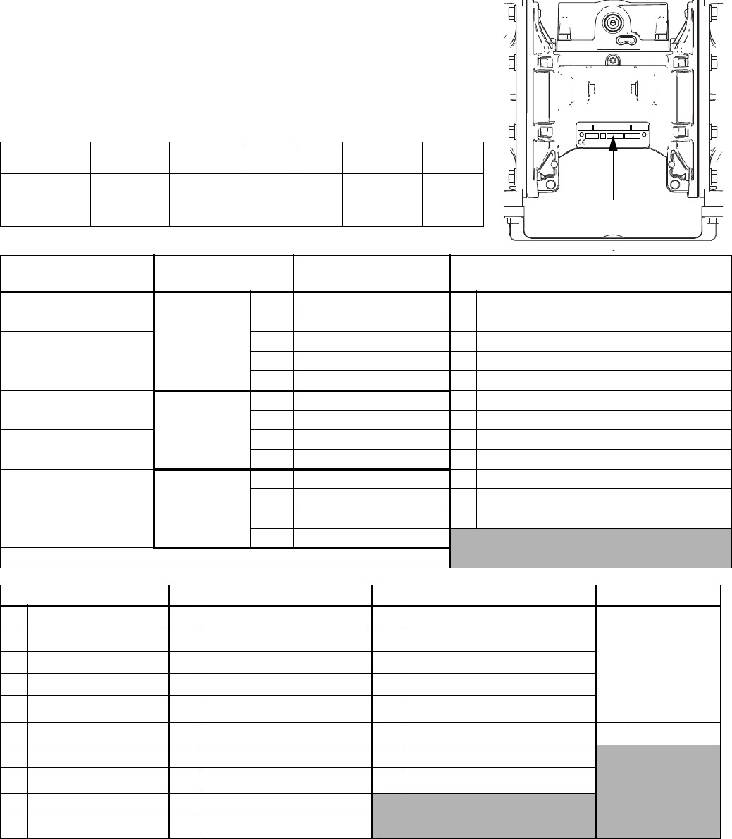
Check the identification plate (ID) for the 20-digit Configuration Number
of your pump. Use the following matrix to define the components of your
pump.
Sample Configuration Number
1050A A01A A1 SS BN BN PT
Pump Model Center
Section and
Air Valve
Fluid
Covers and
Manifolds
Seats Balls Diaphragms Manifold
O-Rings
Pump Model
(1 inch ports, 50 gpm)
Center Section and
Air Valve Material
Air Valve/Monitoring Fluid Covers and Manifolds
1050A★
Aluminum
A01A Standard A1 Aluminum, standard ports, inch
Aluminum A01B Pulse Count✖A2 Aluminum, standard ports, metric
1050C★A01C DataTrak✖C1 Conductive polypropylene, center flange
Conductive A01D Remote C2 Conductive polypropylene, end flange
Polypropylene A01E Optional FKM Seals F1 PVDF, center flange
1050F
Conductive
Polypropylene
C01A Standard F2 PVDF, end flange
PVDF C01B Pulse Count✖H1 Hastelloy, standard ports, inch
1050H‡C01C DataTrak✖H2 Hastelloy, standard ports, metric
Hastelloy C01D Remote P1 Polypropylene, center flange
1050P
Polypropylene
P01A Standard P2 Polypropylene, end flange
Polypropylene P01B Pulse Count✖S1 Stainless steel, standard ports, inch
1050S‡P01C DataTrak✖S2 Stainless steel, standard ports, metric
Stainless Steel P01D Remote
★, ‡, or ✖: See ATEX Certifications, on page 5.
CONFIGURATION NO.PART NO. SERIAL NO.
SERIESDATE CODE MAX WPR PSI-bar MADE IN
Pump Configuration
Number
ti14103a
Check Valve Seats Check Valve Balls Diaphragm Manifold O-Rings
AC Acetal AC Acetal BN Buna-N —Models with
Buna-N, FKM
Fluoroelasto-
mer or TPE
seats do not
use o-rings.
AL Aluminum BN Buna-N CO Polychloroprene Overmolded
BN Buna-N CR Polychloroprene Standard FK FKM Fluoroelastomer
FK FKM Fluoroelastomer CW Polychloroprene Weighted GE Geolast
GE Geolast®FK FKM Fluoroelastomer PO PTFE/EPDM Overmolded
PP Polypropylene GE Geolast PT PTFE/EPDM Two-Piece PT PTFE
PV PVDF PT PTFE SP Santoprene
SP Santoprene®SP Santoprene TP TPE
SS 316 Stainless Steel SS 316 Stainless Steel
TP TPE TP TPE
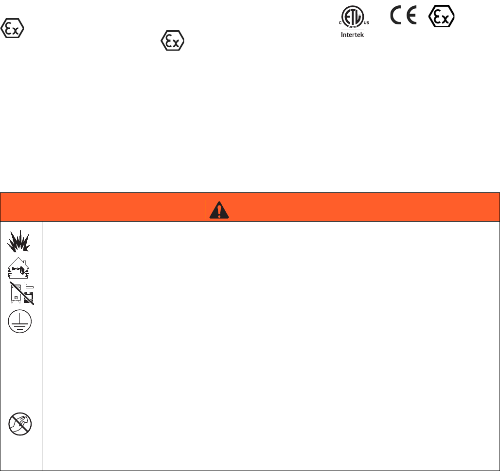
ATEX Certifications
313435T 5
ATEX Certifications
Warnings
The following warnings are for the setup, use, grounding, maintenance, and repair of this equipment. The exclama-
tion point symbol alerts you to a general warning and the hazard symbol refers to procedure-specific risk. When
these symbols appear in the body of this manual, refer back to these Warnings. Additional, product-specific warnings
may be found throughout the body of this manual where applicable.
★ All 1050A (Aluminum) and
1050C (Conductive Polypropylene)
pumps are certified:
II 2 GD c IIC T4
‡ 1050S (Stainless Steel) and 1050H
(Hastelloy) pumps with aluminum or
conductive polypropylene centers are
certified:
II 2 GD c IIC T4
✖ DataTrak and Pulse Count are
certified:
0359 II 1 G
Ex ia IIA T3 Ga
ITS13ATEX27862X
9902471
Class I, Div. 1,
Group D T3A
WARNING
FIRE AND EXPLOSION HAZARD
Flammable fumes, such as solvent and paint fumes, in work area can ignite or explode. To help prevent
fire and explosion:
• Use equipment only in well ventilated area.
• Eliminate all ignition sources; such as pilot lights, cigarettes, portable electric lamps, and plastic drop
cloths (potential static arc).
• Keep work area free of debris, including solvent, rags and gasoline.
• Do not plug or unplug power cords, or turn power or light switches on or off when flammable fumes
are present.
• Ground all equipment in the work area. See Grounding instructions.
• Use only grounded hoses.
• Hold gun firmly to side of grounded pail when triggering into pail.
• If there is static sparking or you feel a shock, stop operation immediately. Do not use equipment
until you identify and correct the problem.
• Keep a working fire extinguisher in the work area.
Static charge may build up on plastic parts during cleaning and could discharge and ignite flammable
materials and gases. To help prevent fire and explosion:
• Clean plastic parts in a well ventilated area.
• Do not clean with a dry cloth.
• Do not operate electrostatic guns in equipment work area.
Warnings
6313435T
EQUIPMENT MISUSE HAZARD
Misuse can cause death or serious injury.
• Do not operate the unit when fatigued or under the influence of drugs or alcohol.
• Do not exceed the maximum working pressure or temperature rating of the lowest rated system
component. See Technical Data in all equipment manuals.
• Use fluids and solvents that are compatible with equipment wetted parts. See Technical Data in all
equipment manuals. Read fluid and solvent manufacturer’s warnings. For complete information
about your material, request MSDS from distributor or retailer.
• Do not leave the work area while equipment is energized or under pressure. Turn off all equipment
and follow the Pressure Relief Procedure in this manual when equipment is not in use.
• Check equipment daily. Repair or replace worn or damaged parts immediately with genuine manu-
facturer’s replacement parts only.
• Do not alter or modify equipment.
• Use equipment only for its intended purpose. Call your distributor for information.
• Route hoses and cables away from traffic areas, sharp edges, moving parts, and hot surfaces.
• Do not kink or over bend hoses or use hoses to pull equipment.
• Keep children and animals away from work area.
• Comply with all applicable safety regulations.
PRESSURIZED EQUIPMENT HAZARD
Fluid from the gun/dispense valve, leaks, or ruptured components can splash in the eyes or on skin and
cause serious injury.
• Follow Pressure Relief Procedure in this manual, when you stop spraying and before cleaning,
checking, or servicing equipment.
• Tighten all fluid connections before operating the equipment.
• Check hoses, tubes, and couplings daily. Replace worn or damaged parts immediately.
THERMAL EXPANSION HAZARD
Fluids subjected to heat in confined spaces, including hoses, can create a rapid rise in pressure due to
the thermal expansion. Over-pressurization can result in equipment rupture and serious injury.
• Open a valve to relieve the fluid expansion during heating.
• Replace hoses proactively at regular intervals based on your operating conditions.
PRESSURIZED ALUMINUM PARTS HAZARD
Use of fluids that are incompatible with aluminum in pressurized equipment can cause serious chemical
reaction and equipment rupture. Failure to follow this warning can result in death, serious injury, or prop-
erty damage.
• Do not use 1,1,1-trichloroethane, methylene chloride, other halogenated hydrocarbon solvents or
fluids containing such solvents.
• Many other fluids may contain chemicals that can react with aluminum. Contact your material
supplier for compatibility.
PLASTIC PARTS CLEANING SOLVENT HAZARD
Use only compatible water-based solvents to clean plastic structural or pressure-containing parts. Many
solvents can degrade plastic parts and cause them to fail, which could cause serious injury or property
damage. See Technical Data in this and all other equipment instruction manuals. Read fluid and solvent
manufacturer’s warnings.
WARNING
Warnings
313435T 7
TOXIC FLUID OR FUMES HAZARD
Toxic fluids or fumes can cause serious injury or death if splashed in the eyes or on skin, inhaled, or
swallowed.
• Read MSDS’s to know the specific hazards of the fluids you are using.
• Route exhaust away from work area. If diaphragm ruptures, fluid may be exhausted with air.
• Store hazardous fluid in approved containers, and dispose of it according to applicable guidelines.
BURN HAZARD
Equipment surfaces and fluid that’s heated can become very hot during operation. To avoid severe
burns:
• Do not touch hot fluid or equipment.
PERSONAL PROTECTIVE EQUIPMENT
You must wear appropriate protective equipment when operating, servicing, or when in the operating
area of the equipment to help protect you from serious injury, including eye injury, inhalation of toxic
fumes, burns, and hearing loss. This equipment includes but is not limited to:
• Clothing and respirator as recommended by the fluid and solvent manufacturer
• Protective eyewear, gloves, and hearing protection.
WARNING
Troubleshooting
8313435T
Troubleshooting
Problem Cause Solution
Pump cycles but will not prime. Pump is running too fast, causing
cavitation before prime
Lower air inlet pressure.
Check valve ball severely worn or
wedged in seat or manifold.
Replace ball and seat. See page 14.
Seat severely worn. Replace ball and seat. See page 14.
Outlet or inlet clogged. Unclog.
Inlet or outlet valve closed. Open.
Inlet fittings or manifolds loose. Tighten.
Manifold o-rings damaged. Replace o-rings. See page 14.
Pump cycles at stall or fails to hold
pressure at stall.
Worn check valve balls, seats, or
o-rings.
Replace. See page 28.
Pump will not cycle, or cycles once
and stops.
Air valve is stuck or dirty. Disassemble and clean air valve. See
page 11. Use filtered air.
Check valve ball severely worn and
wedged in seat or manifold.
Replace ball and seat. See page 14.
Pilot valve worn, damaged, or
plugged.
Replace pilot valve. See page 15.
Air valve gasket damaged. Replace gasket. See page 10.
Check valve ball is wedged into seat
due to overpressurization.
Install pressure relief kit. See Acces-
sories, page 31.
Dispensing valve clogged. Relieve pressure and clear valve.
Air tubing is plugged
(remote air control models).
Clear tube.
Pump operates erratically. Clogged suction line. Inspect; clear.
Sticky or leaking check valve balls. Clean or replace. See page 14.
Diaphragm (and backup) ruptured. Replace. See page 15.
Restricted exhaust. Remove restriction.
Pilot valves damaged or worn. Replace pilot valves. See page 15.
Air valve damaged. Replace air valve. See page 10.
Air valve gasket damaged. Replace air valve gasket. See
page 10.
Air supply erratic. Repair air supply.
Exhaust muffler icing. Use drier air supply or use low ice
muffler (Graco part 102656).

Troubleshooting
313435T 9
Air bubbles in fluid. Suction line is loose. Tighten.
Diaphragm (and backup) ruptured. Replace. See page 15.
Loose manifolds, damaged seats or
manifold o-rings.
Tighten manifold bolts or replace
seats or o-rings. See page 14.
Diaphragm shaft bolt o-ring dam-
aged.
Replace o-ring.
Pump cavitation. Reduce pump speed or suction lift.
Loose diaphragm shaft bolt. Tighten.
Exhaust air contains fluid being
pumped.
Diaphragm (and backup) ruptured. Replace. See page 15.
Loose diaphragm shaft bolt. Tighten or replace. See page 15.
Diaphragm shaft bolt o-ring dam-
aged.
Replace o-ring. See page 15.
Moisture in exhaust air. High inlet air humidity. Use drier air supply.
Pump exhausts excessive air at stall. Worn air valve cup or plate. Replace cup and plate. See page 11.
Damaged air valve gasket. Replace gasket. See page 10.
Damaged pilot valve. Replace pilot valves. See page 15.
Worn shaft seals or bearings. Replace shaft seals or bearings. See
page 15.
Air tubing is damaged or loose
(remote air control models).
Replace tubing or secure connection.
Remote air pressure is higher than
pump air pressure (remote air control
models).
Regulate remote pilot air pressure to
be equal to or less than main air.
Pump leaks air externally. Air valve or fluid cover screws loose. Tighten.
Diaphragm damaged. Replace diaphragm. See page 15.
Air valve gasket damaged. Replace gasket. See page 10.
Remote air pressure is higher than
pump air pressure (remote air control
models).
Regulate remote pilot air pressure to
be equal to or less than main air.
Pump leaks fluid externally from
joints.
Loose manifold screws or fluid cover
screws.
Tighten manifold screws or fluid
cover screws. See page 18.
Manifold o-rings worn out. Replace o-rings. See page 14.
Pump leaks fluid externally through
manifold or fluid cover.
Excessive pump speed or inlet
starvation.
Replace manifold and reduce pump
speed or improve pump feed.
Problem Cause Solution
Repair
10 313435T
Repair
Pressure Relief Procedure
1. Shut off the air supply to the pump.
2. Open the dispensing valve, if used.
3. Open the fluid drain valve to relieve fluid pressure.
Have a container ready to catch the drainage.
Repair or Replace Air Valve
Replace Complete Air Valve
1. Stop the pump. Relieve the pressure. See Pressure
Relief Procedure in previous section.
2. Disconnect the air line to the motor.
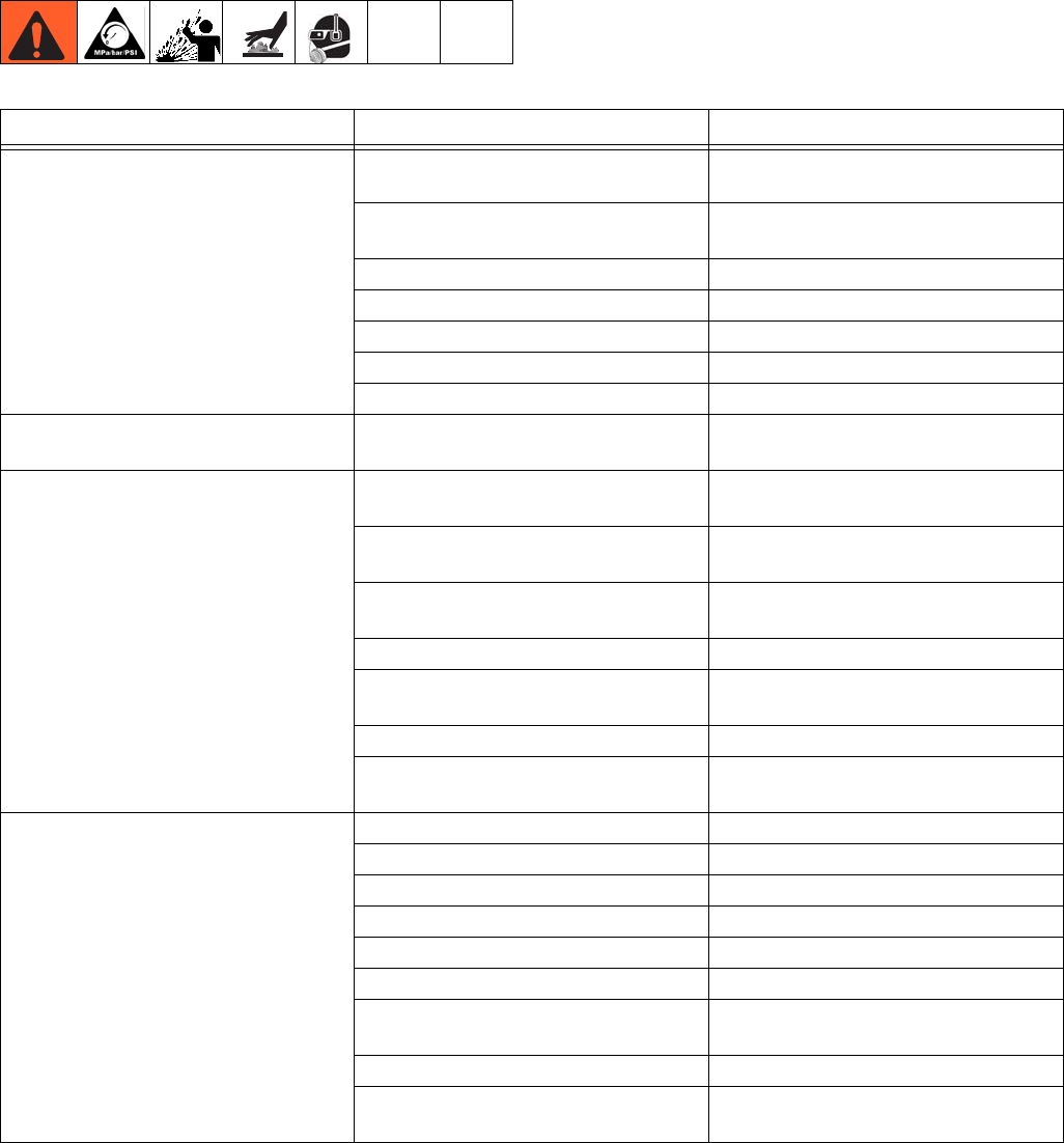
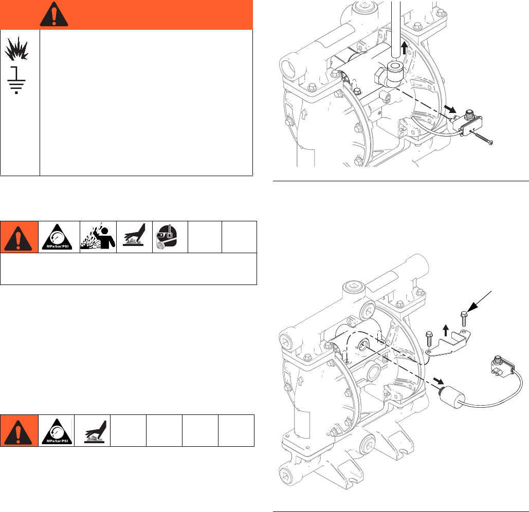
3. For motors with Pulse Count or DataTrak:
Remove screw to disconnect the reed switch
assembly from the air valve.
4. For motors with DataTrak: Remove two screws
and the solenoid bracket. Pull the solenoid out of the
air valve.
5. Remove screws (109, metal pumps) or nuts (112,
plastic pumps). Remove the air valve and gasket
(108).
6. To repair the air valve, go to Disassemble the Air
Valve, step 1, in next section. To install a replace-
ment air valve, continue with step 7.
7. Align the new air valve gasket (108) on the center
housing, then attach the air valve. See Torque
Instructions, page 18.
SPECIAL CONDITIONS FOR SAFE USE
Equipment must comply with the following
conditions to avoid a hazardous condition
which can cause fire or explosion.
• All label and marking material must be
cleaned with a damp cloth (or equiva-
lent).
• The electronic monitoring system is
required to be grounded. See Grounding
instructions in your pump operation man-
ual.
Trapped air can cause the pump to cycle unexpectedly,
which could result in serious injury from splashing.
WARNINGWARNINGWARNING
WARNING
FIG. 1. Reed switch assembly and air line removal
FIG. 2. Solenoid removal
ti14094a
ti14095a
Aluminum Model
Shown
109
Repair
313435T 11
8. For motors with DataTrak: Remember to reattach
the solenoid bracket and the solenoid.
9. For motors with Pulse Count or DataTrak: Use
screw to attach the reed switch assembly to the new
air valve. Reconnect cable.
10. Reconnect the air line to the motor.
Replace Seals or Rebuild Air Valve
NOTE: Repair kits are available. See page 25 to order
the correct kit(s) for your pump. Air Valve Seal Kit parts
are marked with a †. Air Valve Repair Kit parts are
marked with a ◆. Air Valve End Cap Kit parts are
marked with a ✠.
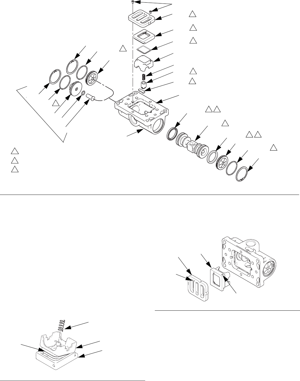
Disassemble the Air Valve
1. Perform steps 1-5 under Replace Complete Air
Valve, page 10.
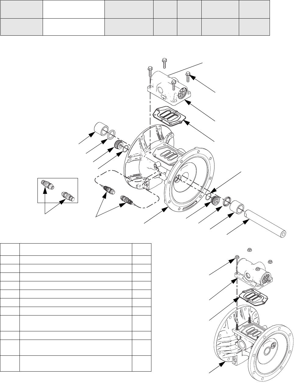
2. See FIG. 4. Use a Torx screwdriver (T8 for aluminum
centers, T9 for plastic centers) to remove two
screws (209). Remove the valve plate (205),
cup assembly (212-214), spring (211), and detent
assembly (203).
3. Pull the cup (213) off of the base (212). Remove the
o-ring (214) from the cup.
4. See FIG. 4. Remove the retaining ring (210) from
each end of the air valve. Use the piston (202) to
push the end caps (207, 217) out of the ends.
Remove end cap o-rings (206). If pump model is
equipped with a runaway protection solenoid, also
remove the solenoid release button (218) and
o-ring (219).
5. Remove the u-cup seals (208) from each end of the
piston (202), then remove the piston. Remove the
detent cam (204) from the air valve housing (201).
Reassemble the Air Valve
NOTE: Apply lithium-based grease whenever instructed
to grease.
1. Use all parts in the repair kits. Clean other parts and
inspect for damage. Replace as needed.
2. Grease the detent cam (204) and install into hous-
ing (201).
3. Grease the u-cups (208) and install on the piston
with lips facing toward the center of the piston.
4. Grease both ends of the piston (202) and install it in
the housing (201), with the flat side toward the cup
(212). Be careful not to tear u-cups (208) when slid-
ing piston into housing.
5. Standard or Pulse Count models (no runaway
protection solenoid): Grease new o-rings (206)
and install on the end caps (207). Install the end
caps into the housing.
DataTrak models (with runaway protection sole-
noid): Orient the air valve so the air inlet faces for-
ward. Grease and install new o-ring (206) on
right-side end cap (207). Grease and install new
o-ring (206) and the solenoid release button (218)
and o-ring (219) on left-side end cap (217). Install
the end caps into the housing.
6. Install a retaining ring (210) on each end to hold end
caps in place.
FIG. 3. Air valve u-cup installation
Lips face down
Lips face up
208◆†
208◆†
202◆
ti12754a
Repair
12 313435T
7. Grease and install the detent assembly (203) into
the piston. Install the o-ring (214) on the cup (213).
Apply a light film of grease to the outside surface of
the o-ring and the inside mating surface of the base
(212).
Orient the end of the base that has a magnet toward
the end of the cup that has the larger cutout.
Engage the opposite end of the parts. Leave the
end with the magnet free. Tilt the base toward the
cup and fully engage the parts, using care so that
the o-ring remains in place. Install the spring (211)
onto the protrusion on the cup. Align the magnet in
the base with the air inlet and install the cup assem-
bly.
8. Grease the cup side and install the valve plate
(205). Align the small hole in the plate with the air
inlet. Tighten the screws (209) to hold it in place.
FIG. 4. Air valve assembly
210✠
210✠
207✠
217✠
206◆†✠
206◆†✠
208◆†
202◆
208◆†
209◆†
205◆
212◆
211◆
203◆
204◆
218✠
219✠
ti14026b
201
Apply lithium-based grease.
1
1
1
1
1
1
3
U-cup lips must face piston.
2
2
2
210✠
206◆†✠
DataTrak Models
with Runaway
Protection 207✠
1
1
1
air
inlet
214◆1
213◆
3
Apply lithium-based grease to
contact surface.
3
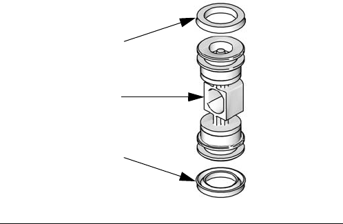
FIG. 5
211
213
212
214
ti19675a
FIG. 6. Air valve cup and plate installation
magnet ti14097b
205 212
small
hole

Repair
313435T 13
DataTrak
NOTE: See DataTrak manual, 313840, for all DataTrak
service and repair information.
Replace DataTrak Battery or Fuse
To reduce the risk of fire and explosion, the
battery and fuse must be replaced in a
non-hazardous location. Follow all instruc-
tions in your pump operation manual.
Use only an approved replacement battery,
and an approved fuse (see pump operation
manual). Use of an unapproved battery or
fuse will void Graco’s warranty and Intertek
and Ex approvals.
WARNINGWARNINGWARNING
WARNING
Repair
14 313435T
Check Valve Repair
NOTE: Kits are available for new check valve balls and
seats in a range of materials. See page 28 to order kits
in the material(s) desired. An o-ring kit and fastener kits
also are available.
NOTE: To ensure proper seating of the check balls,
always replace the seats when replacing the balls. Also,
on models with manifold o-rings, replace the o-rings.
Disassembly
1. Follow the Pressure Relief Procedure on page 10.
Disconnect all hoses.
2. Remove the pump from its mounting.
NOTE: For plastic pumps (1050P, 1050C, and 1050F),
use hand tools only until thread-locking adhesive
patch releases.
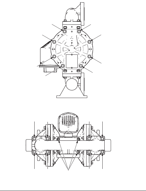
3. Use a 10 mm socket wrench to remove the outlet
manifold fasteners (6). See FIG. 7.
4. Remove the o-rings (12, not used on some models),
seats (10), and balls (11).
5. Turn the pump over and remove the inlet manifold.
Remove the o-rings (12, not used on some models),
seats (10), and balls (11).
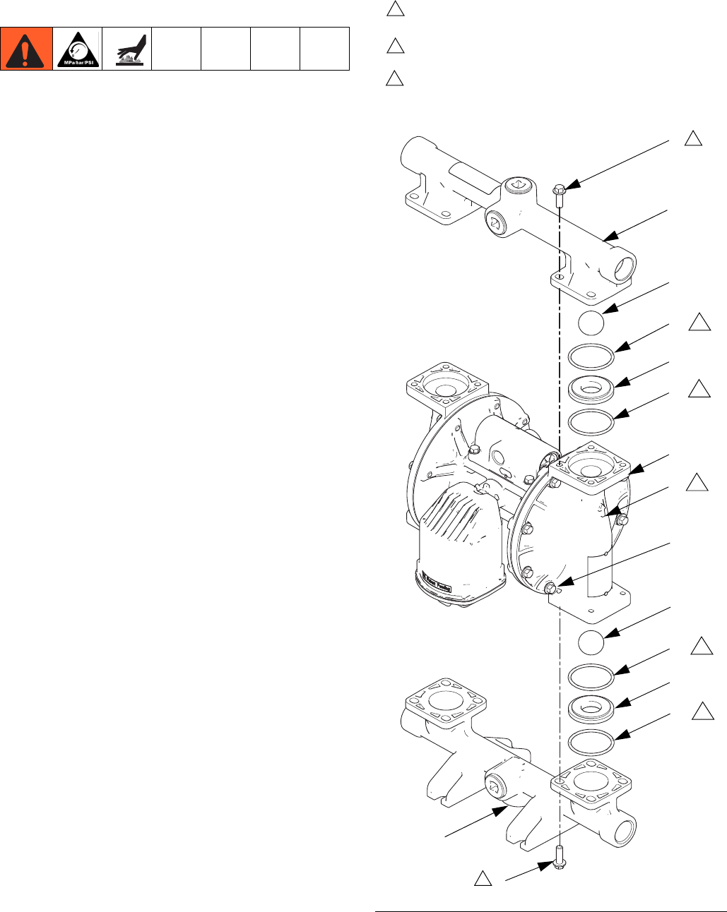
Reassembly
1. Clean all parts and inspect for wear or damage.
Replace parts as needed.
2. Reassemble in the reverse order, following all notes
in FIG. 7. Be sure the ball checks (10-12) and mani-
folds (4, 5) are assembled exactly as shown. The
arrows (A) on the fluid covers must point toward the
outlet manifold (4).
FIG. 7. Ball check valve assembly
Torque to 100 in-lb (11.3 N•m). See Torque Instructions,
page 18.
1
Not used on some models.
3
ti14098a
6
4
11
12
10
12
3
6
5
Arrow (A) must point toward outlet manifold.
2
1
1
2
A
10
12
12
3
3
3
3
11
Aluminum pump
shown
7

Repair
313435T 15
Diaphragms and Center Section
Disassembly
NOTE: Diaphragm kits are available in a range of mate-
rials and styles. See page 29 to order the correct dia-
phragms for your pump. A Center Rebuild Kit also is
available. See page 23. Parts included in the Center
Rebuild Kit are marked with an *. For best results, use
all kit parts.
1. Follow the Pressure Relief Procedure on page 10.
2. Remove the manifolds and disassemble the ball
check valves as explained on page 14.
3. Overmolded Diaphragms
a. Orient the pump so one of the fluid covers faces
up. Use a 10 mm socket wrench to remove the
fluid cover screws (7), then pull the fluid cover
(3) up off the pump.
b. The exposed diaphragm (15) will screw off by
hand from the diaphragm shaft (104). The dia-
phragm shaft bolt will remain attached to the
diaphragm. Remove the air side diaphragm
plate (14).
c. Turn the pump over and remove the other fluid
cover. Pull the diaphragm and shaft up through
the center housing.
d. Grasp the diaphragm firmly and use a wrench
on the flats of the shaft to remove. Also remove
the air side diaphragm plate (14). Continue with
Step 5.
4. All Other Diaphragms
a. Orient the pump so one of the fluid covers faces
up. Use a 10 mm socket wrench to remove the
fluid cover screws (7), then pull the fluid cover
up off the pump. Turn the pump over and
remove the other fluid cover.
b. Plastic Pumps: Use a 1-1/4 socket or box end
wrench on the hex of a fluid side diaphragm
plate to remove. Then remove all parts of the
diaphragm assembly. See FIG. 8.
Metal Pumps: Remove the bolt (304) from one
side of the diaphragm shaft, then remove all
parts of that diaphragm assembly. See FIG. 8.
c. Follow the same procedure to disassemble the
other diaphragm assembly.
5. Inspect the diaphragm shaft (104) for wear or
scratches. If it is damaged, inspect the bearings
(105) in place. If they are damaged, use a bearing
puller to remove them.
NOTE: Do not remove undamaged bearings.
6. Use an o-ring pick to remove the u-cup packings
(106) from the center housing. Bearings (105) can
remain in place.
7. If necessary, use a socket wrench to remove the
pilot valves (101) or pilot inserts (113, remote air
control models).
8. Remove the pilot valve cartridges only if necessary
due to a known or suspected problem. After remov-
ing pilot valves, use a hex to remove the cartridges
(102), then remove cartridge o-rings (103). If
stripped, use two screwdrivers to screw out the car-
tridge.
NOTE: Do not remove undamaged pilot valve
cartridges.
Repair
16 313435T
FIG. 8. Assemble diaphragms and center section
ti14022b
304
301
15
13
14
104* 15
104*
ti14037b
PO and CO
models
304
301
15
13
14
104*
305
14 303
ti14021b
PT models
13
13 (Metal pumps)
(Plastic pumps)
(Metal pumps)
1
Rounded side faces diaphragm.
1
1
1
1
1
Apply lithium-based grease.
2
2
2
2
Torque to 20-25 ft-lb (27-34 N•m)
at 100 rpm maximum.
3
3
3
AIR SIDE markings on diaphragm
must face center housing.
4
44
4
4
If screw comes loose or is
replaced, apply permanent (red)
Loctite® or equivalent to
diaphragm side threads. Apply
primer and medium-strength (blue)
Loctite® or equivalent to shaft side
threads.
5
101* 102*
102*
103*
103*
104*
105*
105*
106*
106*
110
Lips must face out of housing.
6
TP, SP, BN,
FK, and GE
models
5
3
3
ti14025b
2
2
Torque to 20-25 in.-lb (2.3-2.8 N•m).
8
7
(Plastic pumps)
Cartridges (102) must be installed
before pilot valves (101) or inserts
(113, for remote air controls).
7
2
2
2
2
28
26
7
7
2
6
2
113 7
28
(remote air control)
Repair
313435T 17
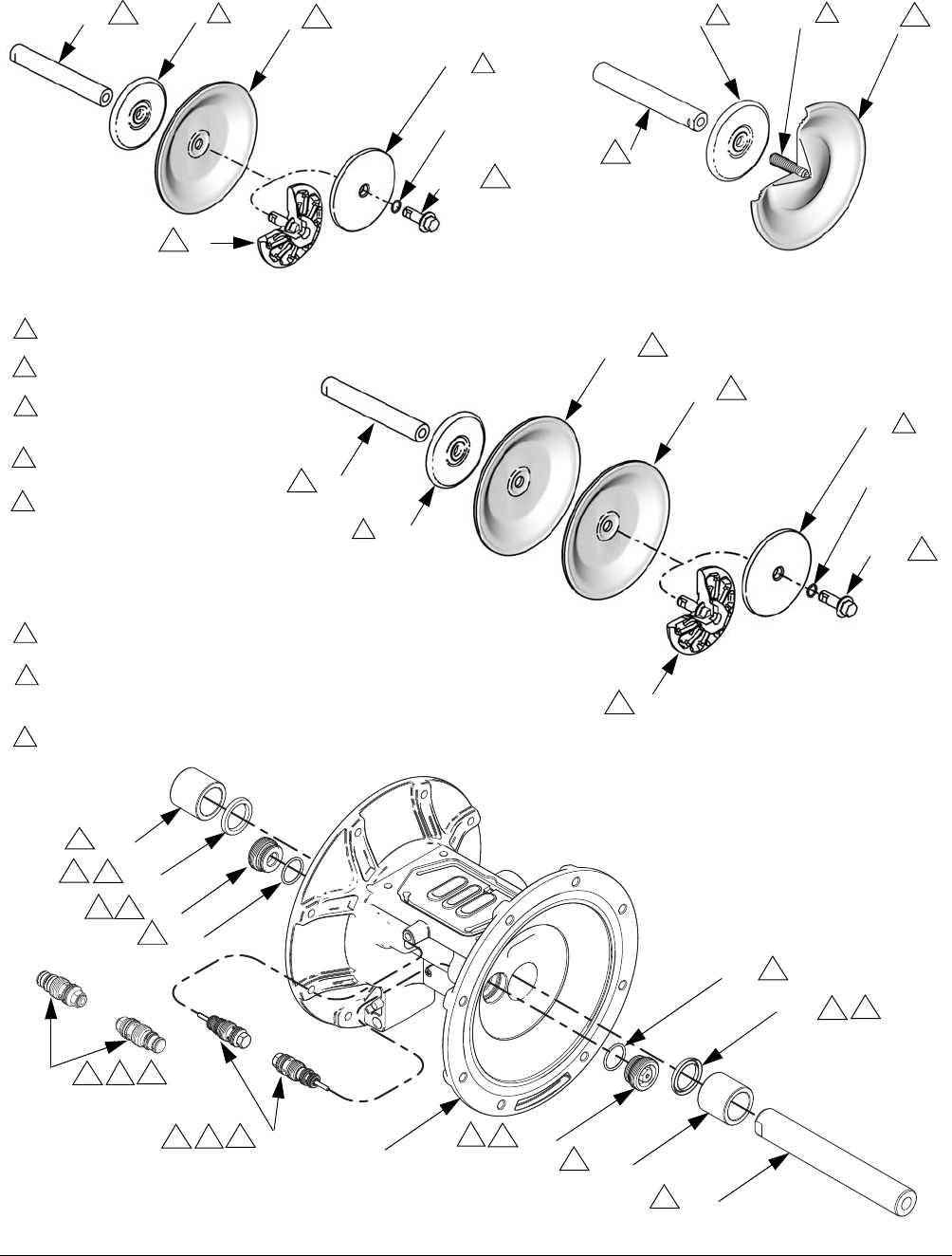
Reassembly
Follow all notes in FIG. 8. These notes contain
important information.
NOTE: Apply lithium-based grease whenever instructed
to grease.
1. Clean all parts and inspect for wear or damage.
Replace parts as needed.
2. If removed, grease and install the new pilot valve
cartridges (102) and cartridge o-rings (103). Screw
in until seated.
NOTE: Cartridges (102) must be installed before pilot
valves (101).
3. Grease and install the pilot valves (101). Torque to
20-25 in.-lb (2.3-2.8 N•m). Do not over-torque.
4. Grease and install the diaphragm shaft u-cup pack-
ings (106) so the lips face out of the housing.
5. If removed, insert the new bearings (105) into the
center housing. Use a press or a block and rubber
mallet to press-fit the bearing so it is flush with the
surface of the center housing.
6. Overmolded Diaphragms:
a. Clamp the shaft flats in a vise.
b. If diaphragm setscrew comes loose or is
replaced, apply permanent (red) Loctite® or
equivalent to diaphragm side threads. Screw
into diaphragm until tight.
c. Assemble the air side plate (14) onto the dia-
phragm. The rounded side of the plate must
face the diaphragm.
d. Apply medium-strength (blue) Loctite or equiva-
lent to the threads of the diaphragm assembly.
Screw the assembly into the shaft as tight as
possible by hand.
e. Grease the shaft u-cups (106) and the length
and ends of the diaphragm shaft (104). Slide
the shaft into the housing.
f. Reattach the first fluid cover (3). See Torque
Instructions, page 18.
g. Repeat Steps b and c for the other diaphragm
assembly. Go to Step 7.
All Other Diaphragms - Metal Pumps:
a. Install the o-ring (301) on the shaft bolt (304).
b. Assemble the fluid side plate (13), the dia-
phragm (15), the backup diaphragm (305, if
present), and the air side diaphragm plate (14)
on the bolt exactly as shown in FIG. 8.
c. Apply medium-strength (blue) Loctite or equiva-
lent to the bolt (304) threads. Screw the bolt into
the shaft hand tight.
d. Grease the shaft u-cups (106) and the length
and ends of the diaphragm shaft (104). Slide
the shaft into the housing.
e. Repeat Steps a-c for the other diaphragm
assembly.
f. Hold one shaft bolt with a wrench and torque
the other bolt to 20-25 ft-lb (27-34 N•m) at 100
rpm maximum. Do not over-torque.
g. Reattach the first fluid cover (3). See Torque
Instructions, page 18. Go to Step 7.
All Other Diaphragms - Plastic Pumps:
a. Assemble the diaphragm (15), the backup dia-
phragm (305, if present), and the air side dia-
phragm plate (14) on the fluid side plate (13)
exactly as shown in FIG. 8.
b. Apply medium-strength (blue) Loctite or equiva-
lent to the threads of the screw on the fluid side
plate. Screw the assembly into the shaft
hand-tight.
c. Grease the shaft u-cups (106) and the length
and ends of the diaphragm shaft (104). Slide
the shaft into the housing.
d. Repeat for the other diaphragm assembly
e. Hold one of the plates with a wrench, and
torque the other plate to 20-25 ft-lb (27-34 N•m)
at 100 rpm maximum. Do not over-torque.
f. Reattach the first fluid cover (3). See Torque
Instructions, page 18.
Repair
18 313435T
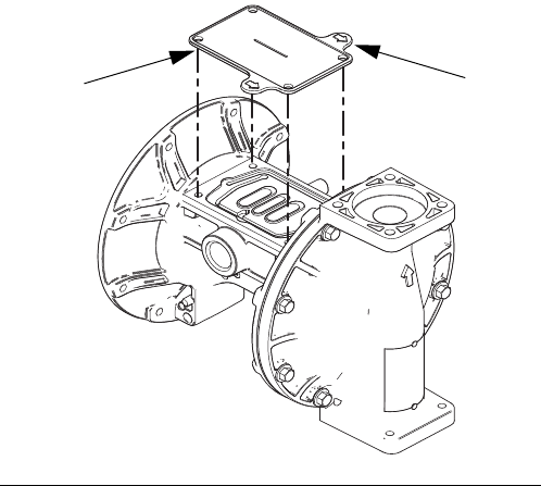
7. To ensure proper seating and extend diaphragm life,
attach the second fluid cover with air pressure on
the pump.
a. See FIG. 9. Place the supplied tool (302) where
the air valve gasket (108) normally goes. Arrows
(A) must face toward the fluid cover that is
already attached.
b. Reattach the air valve.
c. Supply a minimum of 20 psi (0.14 MPa, 1.4 bar)
air pressure to the air valve. Shop air may be
used. The diaphragm will shift so the second
fluid cover will seat properly. Keep air pressure
on until the second fluid cover is attached.
d. Attach the second fluid cover (3). See Torque
Instructions, page 18.
e. Remove the air valve and the tool (302), replace
the gasket (108), and reattach the air valve. See
Torque Instructions, page 18.
NOTE: If you are replacing the diaphragms but not the
air valve, you must remove the air valve and gasket, put
the tool in place of the gasket, and put the air valve back
on to get the air pressure needed for proper installation
of the second fluid cover. Remember to remove the tool
and replace the gasket when finished.
8. Reassemble the ball check valves and manifolds as
explained on page 14.
Torque Instructions
NOTE: Fluid cover and manifold fasteners have a
thread-locking adhesive patch applied to the threads. If
this patch is worn, the screws may loosen during opera-
tion. Replace screws with new ones, or apply medium-
strength (blue) Loctite or equivalent to the threads.
If fluid cover or manifold fasteners have been loosened,
it is important to torque them using the following proce-
dure to improve sealing.
NOTE: Always completely torque fluid covers before
torquing manifolds.
Start all fluid cover screws a few turns. Then turn down
each screw just until head contacts cover. Then turn
each screw by 1/2 turn or less working in a crisscross
pattern to specified torque. Repeat for manifolds.
Fluid cover and manifold fasteners:
100 in-lb (11.3 N•m)
Retorque the air valve fasteners (V) in a crisscross pat-
tern to specified torque.
Air valve fasteners:
55 in-lb (6.2 N•m) for plastic center sections
80 in-lb (9.0 N•m) for metal center sections
FIG. 9. Fluid cover tool
302 A
ti14120a
Repair
313435T 19
FIG. 10. Torque sequence
9
ti18448a
ti18449a

Parts
313435T 21
Parts/Kits Quick Reference
Use this table as a quick reference for parts/kits. See pages indicated in table for full description of kit contents.
▲Replacement Warning labels, signs, tags, and cards
are available at no cost.
Ref. Part/Kit Description Qty.
1 Varies Center Section; not sold separately, see
page 22
1
Aluminum
Conductive Polypropylene
Polypropylene
2 Varies Air Valve; see page 24 1
3 Fluid Cover Kits; see page 26 2
24B653 Aluminum
24C051 Conductive Polypropylene
24D347 Hastelloy
24C050 Polypropylene
24C052 PVDF
24C061 Hastelloy
4 Outlet Manifold Kits; see pages 26-27 1
24B649 Aluminum, npt
24B650 Aluminum, bspt
24C039 Conductive Poly, center flange
24C042 Conductive Poly, end flange
24D343 Hastelloy, npt
24D344 Hastelloy, bspt
24C038 Polypropylene, center flange
24C041 Polypropylene, end flange
24C040 PVDF, center flange
24C043 PVDF, end flange
24C057 Stainless Steel, npt
24C058 Stainless Steel, bspt
5 Inlet Manifold Kits; see page 26-27 1
24B651 Aluminum, npt
24B652 Aluminum, bspt
24C045 Conductive Poly, center flange
24C048 Conductive Poly, end flange
24D345 Hastelloy, npt
24D346 Hastelloy, bspt
24C044 Polypropylene, center flange
24C047 Polypropylene, end flange
24C046 PVDF, center flange
24C049 PVDF, end flange
24C059 Stainless Steel, npt
24C060 Stainless Steel, bspt
6 Manifold Fasteners; 8-pack, see page 27 16
24B654 Aluminum
24C056 Conductive Poly, Poly, and PVDF
24C064 Stainless Steel and Hastelloy
7 Fluid Cover Fasteners; 8-pack,
see page 27
16
24B654 Aluminum
24C055 Conductive Poly, Poly, and PVDF
24C063 Stainless Steel or Hastelloy,
aluminum center
24C056 Stainless Steel or Hastelloy,
plastic center
8 24C617 Plug; 6-pack, aluminum pumps only 6
9 24B910 Pressure Relief Valve; fuel dispense
model only, see page 27
1
10 Seats; 4-pack, includes 8 o-rings where
needed, see page 28
4
24B630 Acetal
24B631 Aluminum
24B632 Buna-N
24B638 FKM Fluoroelastomer
24B633 Geolast
24B635 Polypropylene
24C721 PVDF
24B636 Santoprene
24B637 Stainless Steel
24B634 TPE
11 Check Balls; 4-pack, includes 8 o-rings,
see page 28
4
24B639 Acetal
24B640 Buna-N
24B643 Polychloroprene
24B644 Polychloroprene with SST core
24B648 FKM Fluoroelastomer
24B641 Geolast
24B645 PTFE
24B646 Santoprene
24B647 Stainless Steel
24B642 TPE
12 24B655 Manifold O-Ring (not used on some mod-
els); ptfe, 8-pack, see page 31
8
13 Fluid Side Diaphragm Plate; included in
Air and Fluid Plate Kits, see page 30
2
24C035 Aluminum
24C036 Conductive Polypropylene
24D342 Hastelloy
24C036 Polypropylene
24C037 PVDF
24C062 Stainless Steel
14 ----- Air Side Diaphragm Plate (not visible);
included in Air and Fluid Plate Kits, see
Part 13 or page 30
2
15 Diaphragm Kits; see page 29 2
24B622 Buna-N Standard
24B629 FKM Fluoroelastomer Standard
24B623 Geolast Standard
24B628 Santoprene Standard
24B624 TPE Standard
24B625 Polychloroprene Overmolded
24B626 PTFE Overmolded
24B627 PTFE/EPDM Two-Piece
24F926 PTFE/Santoprene Two-Piece
18 24D642 Muffler; 3/4 npt, polypropylene 1
19 Screw, ground, M5 x 0.8; not shown 1
116343 Pumps with aluminum air valve
116344 Pumps with conductive poly air valve
20▲188621 Label, warning (not shown) 1
Ref. Part/Kit Description Qty.
Parts
22 313435T
Center Section
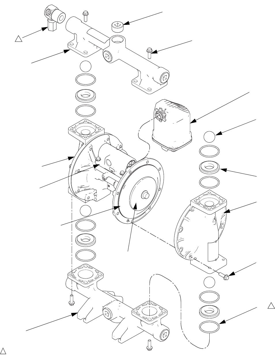
* Included in Center Section Rebuild Kit 24B621
Pump Size
and Material
Center Section Fluid Covers
and Manifolds
Seats Check
Balls
Diaphragm Manifold
O-Rings
1050A A01A A2 AL BN TP PT
Sample Configuration Number
*101 *102
*102
*103 103*
*104
*105
*105
*106
*106
108*
109*
ti14025a
2
Aluminum Center Section
(A01x, AC1x, AU1x, and AU3x)
110
air valve
detail, see
page 24
113
(remote air control)
Ref. Description Qty.
101* VALVE, pilot 2
102* CARTRIDGES, pilot valve receiver 2
103* O-RING, receiver cartridge 2
104* SHAFT, center 1
105* BEARING, center shaft 2
106* U-CUP, center shaft 2
108* GASKET, air valve 1
109* SCREW, M6 x 25, stainless steel, (for
aluminum center section models, Axxx)
4
110 HOUSING, center, not sold separately 1
112* NUTS (for plastic center section models,
C01x and P01x)
4
113 INSERT, remote pilot (for remote air
control models, xxxD)
2
Plastic Center Section
(C01x and P01x)
*112
2
*108
ti14104a
110

Parts
313435T 23
Kits include:
• 2 pilot valves (101)
• 2 pilot cartridges (102)
• 2 cartridge o-rings, buna-N (103)
• 1 center shaft (104)
• 2 center shaft bearings (105)
• 2 center shaft u-cups (106)
• 1 air valve gasket (108)
• 4 bolts, M6 x 25, for A01x pumps (109)
• 4 nuts, for P01x and C01x pumps (112)
• 8 o-rings, PTFE (12)
Kits include:
• 2 pilot valve assemblies (101)
• 2 pilot valve receiver cartridges (102)
• 2 receiver cartridge o-rings (103)
NOTE: xxxD models also require insert kit, shown
below.
Kit 24D043, Remote Pilot Inserts
xxxD (Remote Air Control)
Kit includes:
• 2 remote pilot inserts (113)
All models
Kit includes:
• 1 center shaft (104)
• 2 center shaft bearings (105)
• 2 center shaft u-cups (106)
All models
Kit includes:
• 2 center shaft bearings (105)
• 2 center shaft u-cups (106)
The center housing (110) is not sold separately.
Ground Screws (Ref. 19)
Center Section Rebuild Kits (*)
A01A-A01D, AU1A, AU3A, AC1A,
C01A-C01D,
P01A-P01D
24B621
A01E 24D730
Pilot Valve Assembly Kits
A01A-A01D, AU1A, AU3A, AC1A,
C01A-C01D,
P01A-P01D
24B657
A01E 24C825
Center Shaft Kits
A01A-A01D, AU1A, AU3A, AC1A,
C01A-C01D,
P01A-P01D
24B656
A01E 24D731
Center Shaft Bearing Kits
A01A-A01D, AU1A, AU3A, AC1A,
C01A-C01D,
P01A-P01D
24B658
A01E 24D732
Ground Screw Kits
A01A-A01E,
AU1A, AU3A,
and AC1A
116343
C01A-C01D 116344
P01A-P01D None
Parts
24 313435T
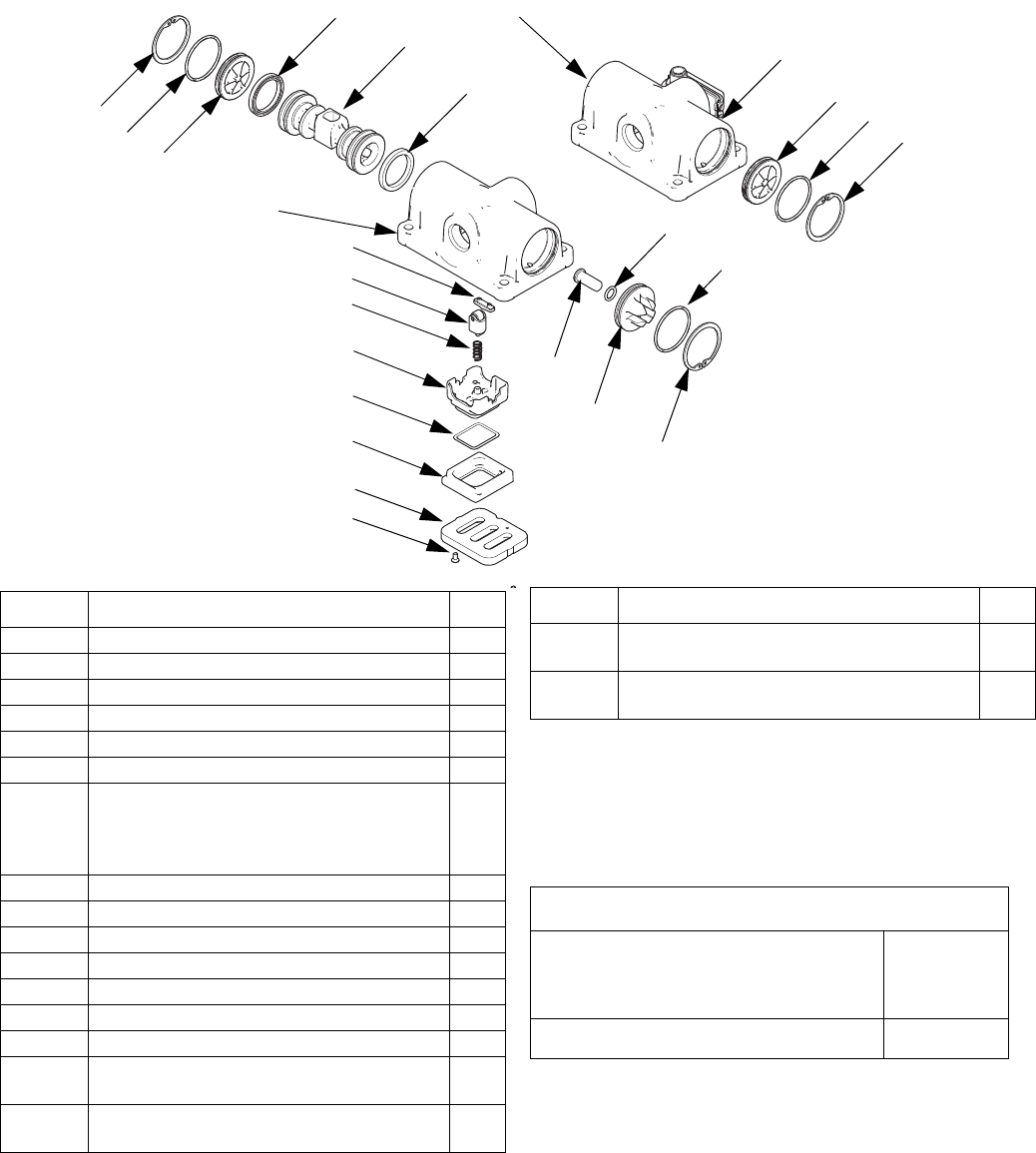
Air Valve and Data Monitoring
◆Parts included in Air Valve Repair Kit. See page 25.
† Parts included in Air Valve Seals Kit. See page 24.
✠ Parts included in Air Valve End Cap Kit. See page
25.
All Models
Kit includes:
• 2 end cap o-rings (206)
• 2 piston u-cups (208)
• 2 screws, M3, shorter (209, for metal pumps)
• 2 screws, #4, longer (209, for plastic pumps)
• 1 solenoid release button o-ring (219)
• 1 air valve gasket (108)
202◆
◆203
◆204
◆205
206◆†✠
206◆†✠
208◆†
◆†209
◆211
◆213 218✠
ti14027b
210✠
217✠
208◆†
210✠
207✠
219◆†✠
201
210✠
206◆†✠
207✠
201
(Compatible with DataTrak
with runaway protection)
Standard (no reed switch) or
Pulse Count (with reed switch)
220
◆214
◆212
Ref. Description Qty.
201 HOUSING, not sold separately 1
202◆PISTON 1
203◆DETENT PISTON ASSEMBLY 1
204◆CAM, detent 1
205◆PLATE, air valve 1
206◆†✠O-RING 2
207✠CAP, end
Standard (xxxA), Pulse Count (xxxB), or
Remote (xxxD)
DataTrak (xxxC)
2
1
208◆† U-CUP 2
209◆†SCREW 2
210◆✠ RETAINING RING 2
211◆DETENT SPRING 1
212◆BASE, cup 1
213◆CUP 1
214◆O-RING, cup 1
217✠CAP, end (for DataTrak models with runaway
protection, xxxC)
1
218✠BUTTON, solenoid release (for DataTrak
models with runaway protection, xxxC)
1
219◆†✠O-RING (for DataTrak models with runaway
protection, xxxC)
1
220 REED SWITCH ASSEMBLY (for Pulse
Count models, xxxB, includes fastener)
1
Air Valve Seal Kits (†)
A01A-A01D, AU1A, AU3A, AC1A,
C01A-C01D,
P01A-P01D
24B769
A01E 24C983
Ref. Description Qty.

Parts
313435T 25
Kits include:
• 1 air valve piston (202)
• 1 detent piston assembly (203)
• 1 detent cam (204)
• 1 air valve plate (205)
• 2 end cap o-rings (206)
• 2 piston u-cups (208)
• 2 screws, M3, shorter (209, for metal pumps)
• 2 screws, #4, longer (209, for plastic pumps)
• 1 detent spring (211)
• 1 air cup base (212)
• 1 air cup (213)
• 1 air cup o-ring (214)
• 1 solenoid release button o-ring (219)
• 1 air valve gasket (108)
Kits include:
• 1 air valve assembly (2)
• 1 air valve gasket (108)
• 4 screws (109; models with aluminum centers)
OR
• 4 nuts (112; models with plastic centers)
Standard or Pulse Count (no runaway protection
solenoid) kits include:
• 2 end caps (207)
• 2 retaining rings (210)
• 2 o-rings (206)
DataTrak (runaway protection solenoid) Kits include:
• 1 standard end cap (207)
• 1 end cap with opening (217)
• 2 retaining rings (210)
• 2 o-rings (206)
• solenoid release button (218)
• o-ring for button (219)
Kits include:
• 1 air valve assembly (2) with restrictor
• 1 air valve gasket (108)
• 4 screws (109; models with aluminum centers)
OR
• 4 nuts (112; models with plastic centers)
• 2 remote pilot inserts
Kit includes:
• reed switch module (220)
• mounting screw
Air Valve Repair Kits (◆)
A01A-A01C, AU1A,
AU3A, AC1A,
C01A-C01C, P01A-P01C
24B768
A01D, C01D, P01D 24D044
A01E 24D699
Air Valve
Replacement Kits
AxxA 24B766
A01B 24B766
A01C 24B767
A01D 24D040
A01E 24C826
C01A 24B775
C01B 24B775
C01C 24B776
C01D 24D042
P01A 24B773
P01B 24B773
P01C 24B774
P01D 24D041
Air Valve End Cap Kits (✠)
AxxA, A01B, or A01D 24A361
A01E 24D734
C01A, C01B, or C01D 24C053
P01A, P01B, or P01D 24C053
A01C 24A363
C01C 24C054
P01C 24C054
Remote Air Control
Conversion Kits
Axxx 24D037
Cxxx 24D039
Pxxx 24D038
Pulse Count Kits
Axxx 24B798
Cxxx or Pxxx 24B796
Parts
26 313435T
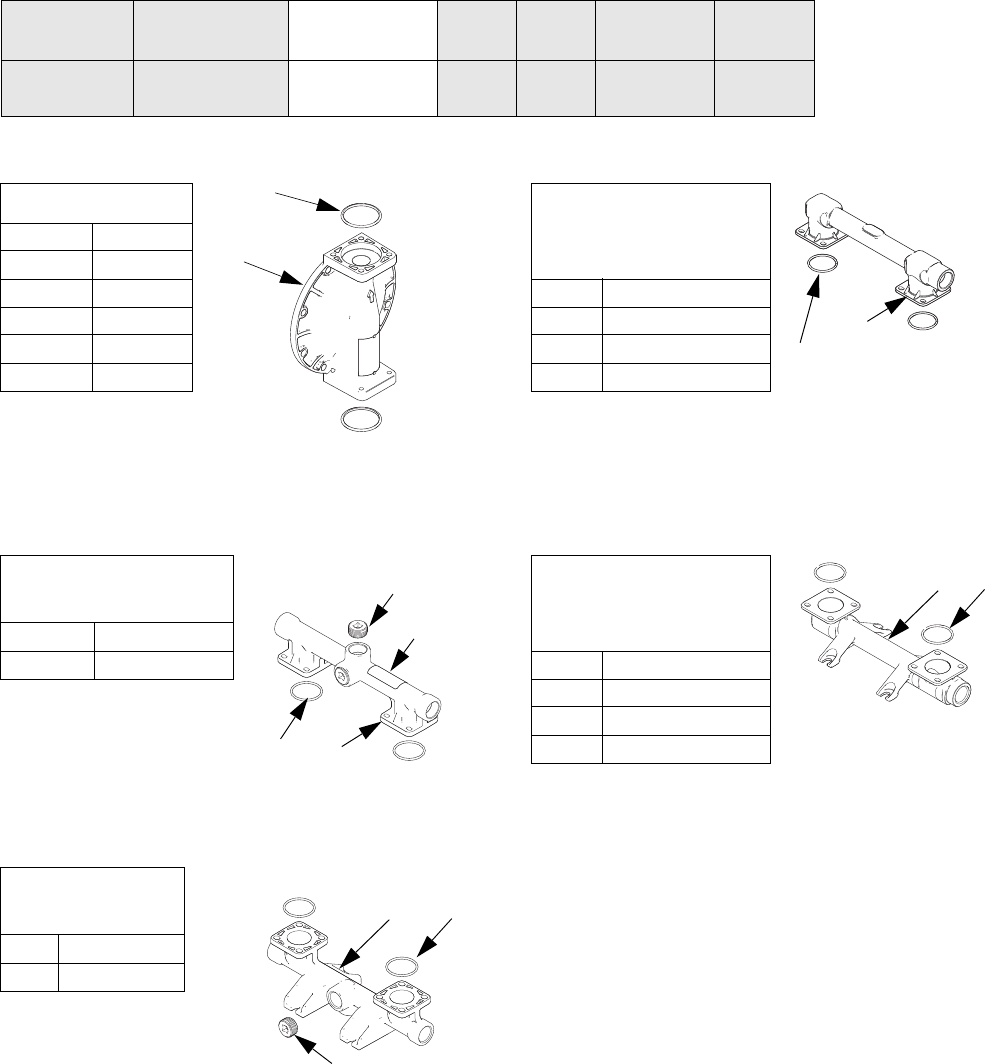
Fluid Covers and Manifolds
Kits include:
• 1 fluid cover (3)
• 4 o-rings, ptfe (12)
Kits include:
• 1 outlet manifold (4)
• 3 pipe plugs (8)
• 4 o-rings, ptfe (12)
• 1 warning label (20▲)
Kits include:
• 1 inlet manifold (5)
• 3 pipe plugs (8)
• 4 o-rings, ptfe (12)
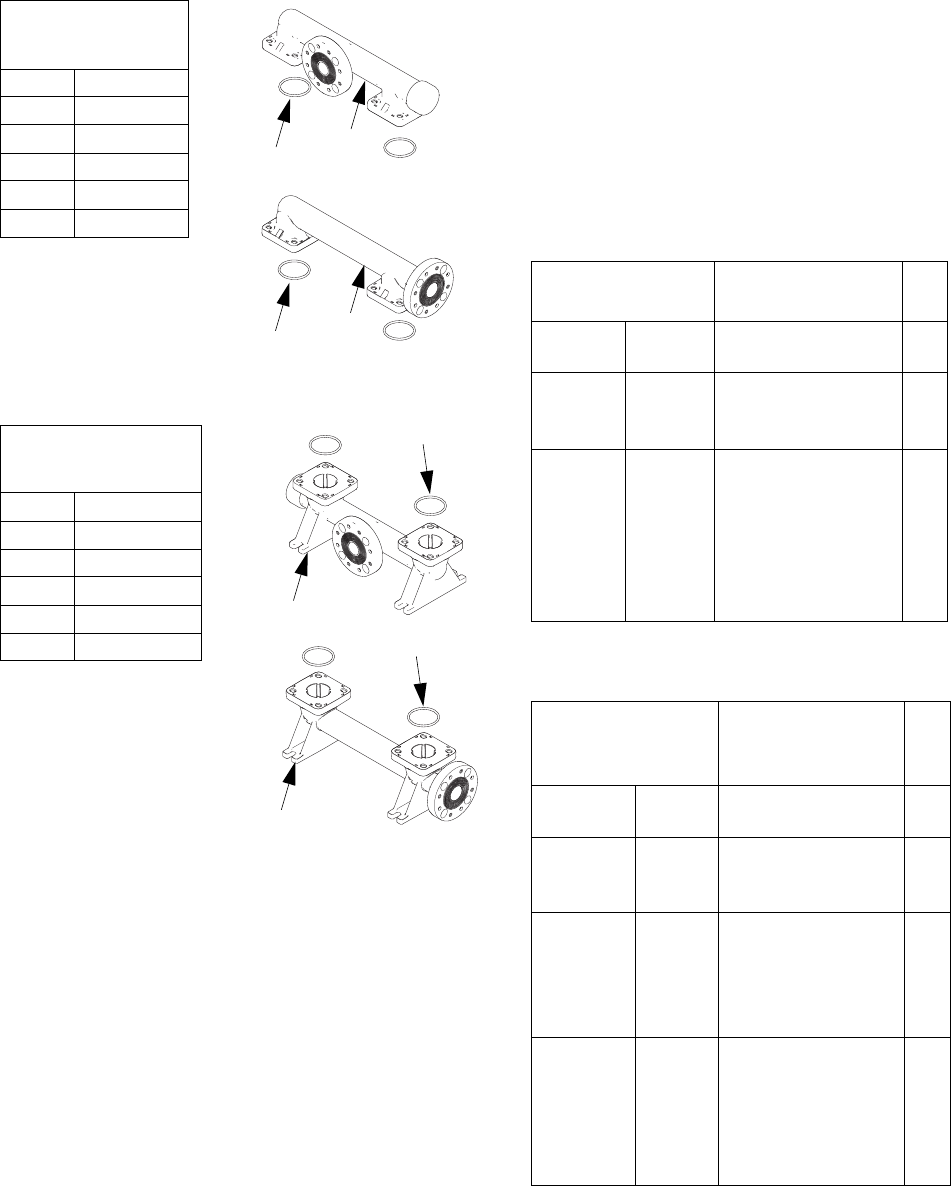
Kits include:
• 1 outlet manifold (4)
• 4 o-rings, ptfe (12)
• 1 warning label (20▲)
Kits include:
• 1 inlet manifold (5)
• 4 o-rings, ptfe (12)
Pump Size
and Material
Air Valve and
Center Section
Fluid Covers
and Manifolds
Seats Check
Balls
Diaphragm Manifold
O-Rings
1050A A01A A1 AL BN TP PT
Sample Configuration Number
Fluid Cover Kits
A1, A2 24B653
C1, C2 24C051
H1, H2 24D347
P1, P2 24C050
F1, F2 24C052
S1, S2 24C061
Aluminum Outlet
Manifold Kits
A1 24B649
A2 24B650
Aluminum Inlet
Manifold Kits
A1 24B651
A2 24B652
12
3
ti14307a
4
12
8
20
ti14308a
512
8
Hastelloy and
Stainless Steel
Outlet Manifold Kits
H1 24D343
H2 24D344
S1 24C057
S2 24C058
Hastelloy and
Stainless Steel
Inlet Manifold Kits
H1 24D345
H2 24D346
S1 24C059
S2 24C060
ti14313a
12
4
ti14314a
512
Parts
313435T 27
Kits include:
• 1 outlet manifold (4)
• 4 o-rings, ptfe (12)
• 1 warning label
(20▲)
Kits include:
• 1 inlet manifold (5)
• 4 o-rings, ptfe (12)
▲ Replacement Danger and Warning tags, labels, and
cards are available at no cost.
Kit 24B910, Fluid Pressure Relief Valve
Fuel Dispense Model only
Kit includes:
• 1 valve, 3/8 nptf (9)
NOTE: See page 31 for manifold o-rings (12).
Manifold Fasteners (Ref. 9)
Fluid Cover Fasteners (Ref. 7)
Plastic Outlet
Manifold Kits
C1 24C039
C2 24C042
P1 24C038
P2 24C041
F1 24C040
F2 24C043
Plastic Inlet
Manifold Kits
C1 24C045
C2 24C048
P1 24C044
P2 24C047
F1 24C046
F2 24C049
ti14309a
ti14311a
4
12
4
12
ti14310a
ti14312a
5
5
12
12
Manifold Fastener
Kits
Fastener
Description Qty.
A1, A2 24B654 BOLT, hex head,
steel, M8 x 25
8
C1, C2
P1, P2,
F1, F2
24C056 BOLT, flange head,
M8 x 32, stainless
steel, includes nuts
8
S1, S2,
H1, H2
with any
center
(Axxx,
Cxxx, or
Pxxx)
24C064 BOLT, hex head, M8
x 20, stainless steel,
includes nuts
8
Fluid Cover
Fastener Kits Description Qty.
A1, A2 24B654 BOLT, hex head,
steel, M8 x 25
8
C1, C2
P1, P2,
F1, F2
24C055 BOLT, flange head,
M8 x 45, stainless
steel, includes nuts
8
S1, S2,
H1, H2
aluminum
center
(Axxx)
24C063 BOLT, flange head,
M8 x 25, stainless
steel
8
S1, S2,
H1, H2
plastic
center
(Cxxx or
Pxxx)
24C056 BOLT, flange head,
M8 x 32, stainless
steel, includes nuts
8

Parts
28 313435T
Seats and Check Ball
Kits include:
• 4 seats, material indicated in table (10)
• 8 o-rings, PTFE, included unless table says “no
o-rings” (12)
NOTE: Some kits may not be available for your model.
See the selector tool at www.graco.com or speak with
your distributor.
Kits Include:
• 4 balls, material indicated in table (11)
• 8 o-rings, PTFE (12)
NOTE: Some kits may not be available for your model.
See the selector tool at www.graco.com or speak with
your distributor.
Pump Size
and Material
Air Valve and
Center Section
Fluid Covers
and Manifolds
Seats Check
Balls
Diaphragm Manifold
O-Rings
1050A A01A A2 AL BN TP PT
Sample Configuration Number
Seat Kits
AC 24B630
AL 24B631
BN (no o-rings) 24B632
FK (no o-rings) 24B638
GE 24B633
PP 24B635
PV 24C721
SP 24B636
SS 24B637
TP (no o-rings) 24B634
Check Ball Kits
AC 24B639
BN 24B640
CR 24B643
CW 24B644
FK 24B648
GE 24B641
PT 24B645
SP 24B646
SS 24B647
TP 24B642
Parts
313435T 29
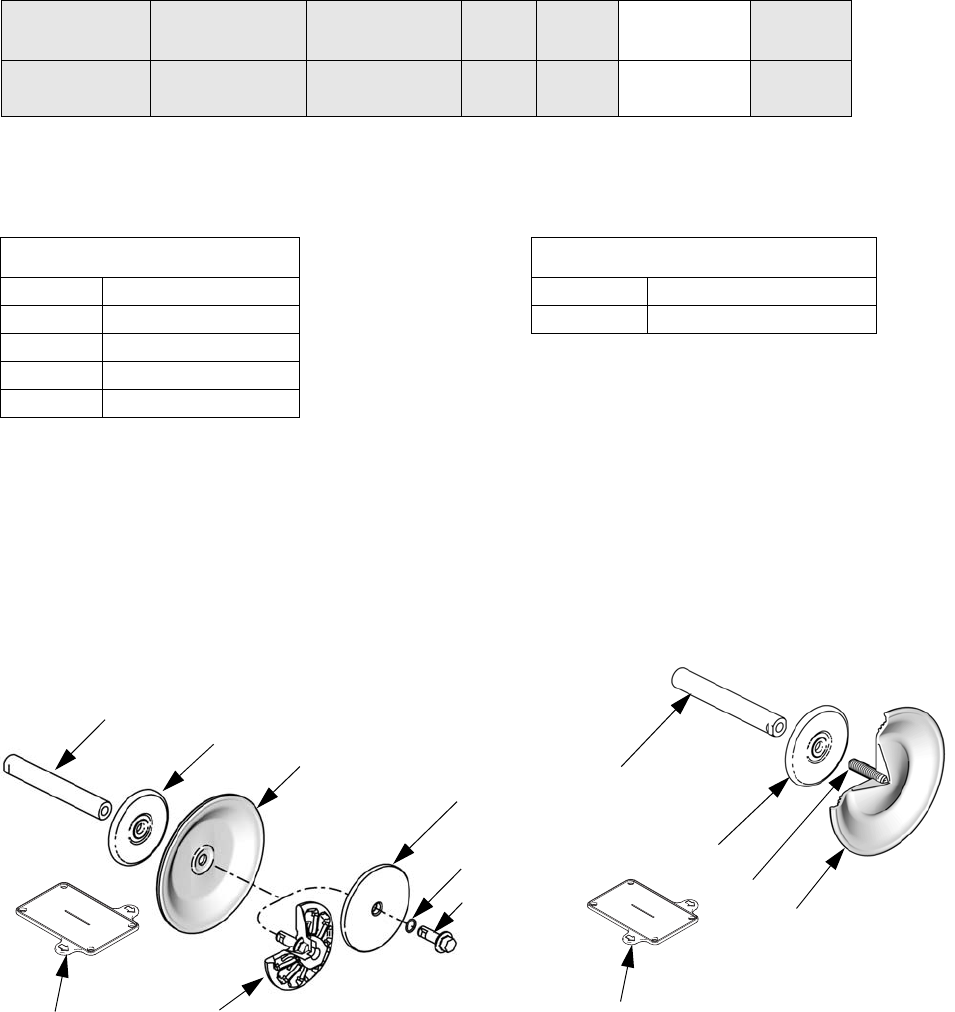
Diaphragms
NOTE: Some kits may not be available for your model. See the selector tool at www.graco.com or speak with your
distributor.
.
Kits include:
• 8 o-rings, ptfe (12)
• 2 diaphragms (15, material indicated in table)
• 2 o-rings for the bolt (301, used only on metal
pumps)
• 1 diaphragm install tool (302)
NOTE: Fluid plates (13, 14) and diaphragm shaft bolts
(304) are sold separately. See page 30. The shaft (104)
is part of Kit 24B621, the Center Section Rebuild Kit.
Kits include:
• 8 o-rings, ptfe (12)
• 2 overmolded diaphragms (15, material indi-
cated in table)
• 2 diaphragm set screws, stainless steel (303)
• 1 diaphragm install tool (302)
NOTE: Fluid plates (14) are sold separately. See page
30. The shaft (104) is part of Kit 24B621, the Center
Section Rebuild Kit.
Pump Size
and Material
Air Valve and
Center Section Fluid Covers
and Manifolds
Seats Check
Balls
Diaphragm Manifold
O-Rings
1050A A01A A2 AL BN TP PT
Sample Configuration Number
Standard Diaphragm Kits
BN 24B622
FK 24B629
GE 24B623
SP 24B628
TP 24B624
ti14022a
304
301
15
13
14
104
13 (Plastic pumps)
(Metal pumps)
302
(not to scale)
Overmolded Diaphragm Kits
CO 24B625
PO 24B626
15
303
14
104
ti14037a
302
(not to scale)
Parts
30 313435T
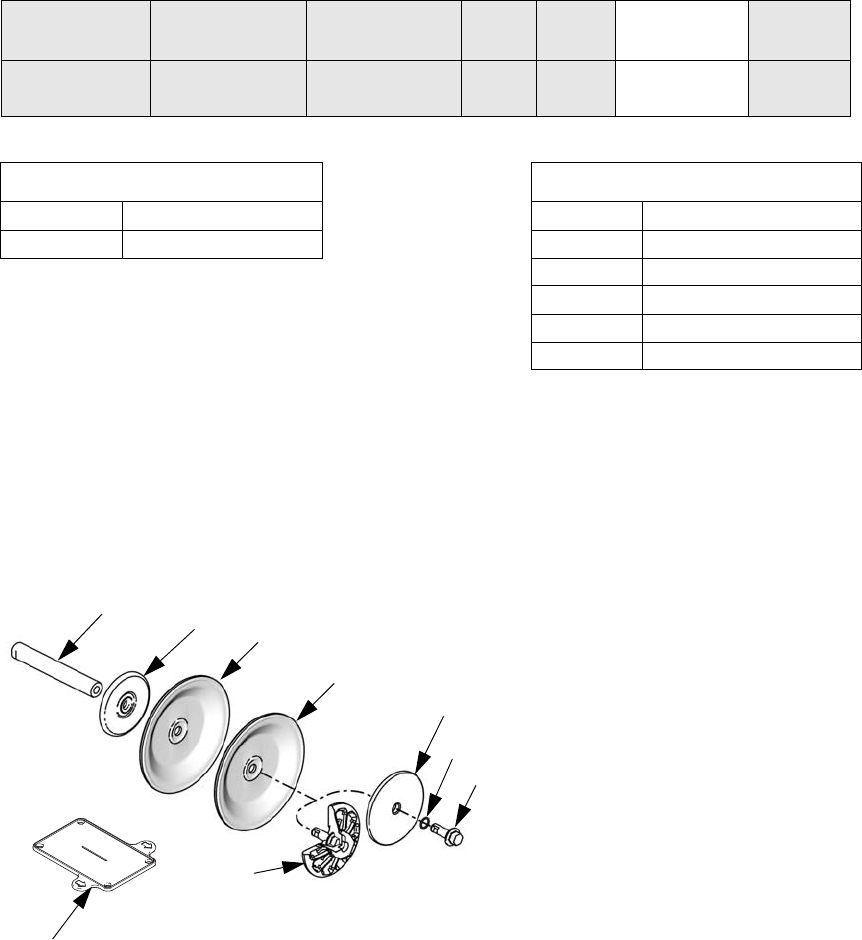
Diaphragms (continued)
Kits include:
• 8 o-rings, PTFE (12)
• 2 diaphragms, PTFE (15)
• 2 backup diaphragms (305, material indicated in
table)
• 2 o-rings for the bolt (301, used only on metal
pumps)
• 1 diaphragm install tool (302)
NOTE: Fluid plates (13, 14) and diaphragm shaft bolts
(304) are sold separately. See page 30. The shaft (104)
is part of Kit 24B621, the Center Section Rebuild Kit.
Kits for aluminum, hastelloy, and stainless steel
pumps include:
• air side diaphragm plate (14)
• fluid side diaphragm plate (13)
• o-ring (301)
• bolt (304)
Kits for polypropylene, conductive polypropylene,
and PVDF pumps include:
• air side diaphragm plate (14)
• fluid side diaphragm plate (13, includes bolt)
Diaphragm Shaft Bolt (Metal Pumps)
Kit 24C099 includes:
• 1 bolt, stainless steel, M12 x 35 (304)
• 1 o-ring (301)
Pump Size
and Material
Air Valve and
Center Section Fluid Covers
and Manifolds
Seats Check
Balls
Diaphragms Manifold
O-Rings
1050A A01A A2 AL BN TP PT
Sample Configuration Number
Two-Piece Diaphragm Kits
PT 24B627
n/a 24F926
304
301
15
13
14
104
305
ti14021a
13 (Metal pumps)
302
(not to scale)
(Plastic pumps)
Air and Fluid Plate Kits
1050A 24C035
1050C 24C036
1050H 24D342
1050P 24C036
1050F 24C037
1050S 24C062

Parts
313435T 31
Manifold O-Rings
Kit Includes:
• 8 o-rings, PTFE (12)
DataTrak
NOTE: See DataTrak manual, 313840, for all DataTrak
related part numbers and kit information, including the
reed switch and solenoid.
Accessories
Fluid Pressure Relief Kit 238428
(for aluminum pumps)
Includes pipe bushings, hose adapter, relief valve, and
tubing.
Fluid Pressure Relief Kit 112119
(for plastic pumps)
Includes fluid pressure relief valve.
Wall Mount Kit 24C637
Includes bracket, 4 dampeners, 8 washers, and 8 lock
nuts.
Wall Bracket Dampener Kit 24E769
Includes 4 dampeners.
Rubber Foot Mounting Kit 236452
Includes washers, nuts, and rubber feet.
Grounding Wire Assembly Kit 238909
Includes ground wire and clamp.
Air Controls Kit 246946
Includes 1/4 npt air filter/regulator with 40 micron ele-
ment and air pressure gauge.
Air Controls Kit 246947
Includes 1/2 npt air filter/regulator with 40 micron ele-
ment and air pressure gauge.
Standard Pipe Flange Kits
239005 - Polypropylene
239008 - Stainless steel
239009 - PVDF
Each kit includes the pipe flange, a PTFE gasket, bolts,
spring lock washers, flat washers and nuts.
Optional Muffler
Part No. 102656, 3/4 npt, aluminum.
Pump Size
and Material
Air Valve and
Center Section
Fluid Covers
and Manifolds
Seats Check
Balls
Diaphragm Manifold
O-Rings
1050A A01A A2 AL BN TP PT
Sample Configuration Number
O-Ring Kit Qty.
PT 24B655 8
-- Model includes no o-rings 0
Technical Data
32 313435T
Technical Data
Maximum fluid working pressure . . . . . . . . . . . . . . . . . . . . . . . . . . . . . . . . . 125 psi (0.86 MPa, 8.6 bar)
Air pressure operating range . . . . . . . . . . . . . . . . . . . . . . . . . . . . . . . . . . . . 20-125 psi (0.14-0.86 MPa, 1.4-8.6 bar)
Fluid displacement per cycle . . . . . . . . . . . . . . . . . . . . . . . . . . . . . . . . . . . . 0.17 gal. (0.64 liters)
Air consumption at 70 psi (0.48 MPa, 4.8 bar), 20 gpm (76 lpm) . . . . . . . . 25 scfm
Maximum values with water as media under submerged inlet
conditions at ambient temperature:
Maximum air consumption . . . . . . . . . . . . . . . . . . . . . . . . . . . . . . . . . . . .
Maximum free-flow delivery . . . . . . . . . . . . . . . . . . . . . . . . . . . . . . . . . . .
Maximum pump speed. . . . . . . . . . . . . . . . . . . . . . . . . . . . . . . . . . . . . . .
Maximum suction lift (varies widely based on ball/seat selection and
wear, operating speed, material properties, and other variables . . . . . . .
67 scfm
50 gpm (189 lpm)
280 cpm
16 ft (4.9 m) dry, 29 ft (8.8 m) wet
Maximum size pumpable solids . . . . . . . . . . . . . . . . . . . . . . . . . . . . . . . . . . 1/8 in. (3.2 mm)
Recommended cycle rate for continuous use . . . . . . . . . . . . . . . . . . . . . . . 93 - 140 cpm
Recommended cycle rate for circulation systems . . . . . . . . . . . . . . . . . . . . 20 cpm
Sound Power*
at 70 psi (0.48 MPa, 4.8 bar) and 50 cpm . . . . . . . . . . . . . . . . . . . . . . . .
at 100 psi (0.7 MPa, 7.0 bar) and full flow . . . . . . . . . . . . . . . . . . . . . . . .
78 dBa
90 dBa
Sound Pressure**
at 70 psi (0.48 MPa, 4.8 bar) and 50 cpm . . . . . . . . . . . . . . . . . . . . . . . .
at 100 psi (0.7 MPa, 7.0 bar) and full flow . . . . . . . . . . . . . . . . . . . . . . . .
84 dBa
96 dBa
Fluid temperature range. . . . . . . . . . . . . . . . . . . . . . . . . . . . . . . . . . . . . . . . see page 33
Air inlet size . . . . . . . . . . . . . . . . . . . . . . . . . . . . . . . . . . . . . . . . . . . . . . . . . 1/2 npt(f)
Fluid inlet size
Aluminum (1050A), Hastelloy (1050H) or Stainless Steel (1050S) . . . . .
Conductive Poly (1050C), Polypropylene (1050P), or PVDF (1050F) . . .
1 in. npt(f) or 1 in. bspt
1 in. raised face ANSI/DIN flange
Fluid outlet size
Aluminum (1050A), Hastelloy (1050H) or Stainless Steel (1050S) . . . . .
Conductive Poly (1050C), Polypropylene (1050P), or PVDF (1050F) . . .
1 in. npt(f) or 1 in. bspt
1 in. raised face ANSI/DIN flange
Weight
Aluminum (1050A) . . . . . . . . . . . . . . . . . . . . . . . . . . . . . . . . . . . . . . . . . .
Conductive Polypropylene (1050C) and Polypropylene (1050P) . . . . . . .
Hastelloy . . . . . . . . . . . . . . . . . . . . . . . . . . . . . . . . . . . . . . . . . . . . . . . . .
PVDF (1050F) . . . . . . . . . . . . . . . . . . . . . . . . . . . . . . . . . . . . . . . . . . . . .
Stainless Steel (1050S)
with conductive polypropylene center . . . . . . . . . . . . . . . . . . . . . . .
with polypropylene center . . . . . . . . . . . . . . . . . . . . . . . . . . . . . . . .
with aluminum center. . . . . . . . . . . . . . . . . . . . . . . . . . . . . . . . . . . .
23 lb. (10.5 kg)
18 lb. (8.2 kg)
41 lb. (18.6 kg)
26 lb (11.8 kg)
36.3 lb. (16.5 kg)
37.3 lb. (16.9 kg)
41.4 lb. (18.8 kg)
Wetted parts include material(s) chosen for seat, ball, and diaphragm
options, plus the pump’s material of construction
1050A. . . . . . . . . . . . . . . . . . . . . . . . . . . . . . . . . . . . . . . . . . . . . . . . . . . .
1050H . . . . . . . . . . . . . . . . . . . . . . . . . . . . . . . . . . . . . . . . . . . . . . . . . . .
1050C and 1050P . . . . . . . . . . . . . . . . . . . . . . . . . . . . . . . . . . . . . . . . . .
1050F. . . . . . . . . . . . . . . . . . . . . . . . . . . . . . . . . . . . . . . . . . . . . . . . . . . .
1050S. . . . . . . . . . . . . . . . . . . . . . . . . . . . . . . . . . . . . . . . . . . . . . . . . . . .
Aluminum
Hastelloy
Polypropylene
PVDF
Stainless Steel

Technical Data
313435T 33
* Sound power measured per ISO-9614-2.
** Sound pressure was tested 3.28 ft (1 m) from equipment.
All trademarks mentioned in this manual are the property of their respective owners.
Fluid Temperature Range
* The maximum temperature listed is based on the ATEX standard for T4 temperature classification. If you are
operating in a non-explosive environment, FKM fluoroelastomer’s maximum fluid temperature in aluminum or
stainless steel pumps is 320°F (160°C).
Non-wetted external parts
Aluminum (1050A) . . . . . . . . . . . . . . . . . . . . . . . . . . . . . . . . . . . . . . . . . .
Hastelloy (1050H). . . . . . . . . . . . . . . . . . . . . . . . . . . . . . . . . . . . . . . . . . .
Plastic (1050P, 1050C, and 1050F) . . . . . . . . . . . . . . . . . . . . . . . . . . . . .
Stainless Steel (1050S) . . . . . . . . . . . . . . . . . . . . . . . . . . . . . . . . . . . . . .
aluminum, coated carbon steel
hastelloy, stainless steel, polypropylene
or aluminum (if used in center section)
stainless steel, polypropylene
stainless steel, polypropylene or alumi-
num (if used in center section)
Reference Information
Maximum Storage Time (varies with conditions) . . . . . . . . . . . . . . . . . . .
Maximum Lifetime (varies with operating conditions and maintenance) .
Power Efficiency Factor (varies based on pump configuration,
operating parameters, and material) . . . . . . . . . . . . . . . . . . . . . . . . . . . .
2 years
10 years
1.61 gal. air consumed/1 gal. fluid
pumped at 70 psi (1.61 liter air con-
sumed/1 liter fluid pumped at 4.8 bar)
NOTICE
Temperature limits are based on mechanical stress only. Certain chemicals will further limit the fluid operating tem-
perature range. Stay within the temperature range of the most-restricted wetted component. Operating at a fluid
temperature that is too high or too low for the components of your pump may cause equipment damage.
Diaphragm/Ball/Seat Material
Fluid Temperature Range
Aluminum, Hastelloy, or
Stainless Steel Pumps
Polypropylene or
Conductive
Polypropylene Pumps PVDF Pumps
Fahrenheit Celsius Fahrenheit Celsius Fahrenheit Celsius
Acetal (AC) 10° to 180°F -12° to 82°C 32° to 150°F 0° to 66°C 10° to 180°F -12° to 82°C
Buna-N (BN) 10° to 180°F -12° to 82°C 32° to 150°F 0° to 66°C 10° to 180°F -12° to 82°C
FKM Fluoroelastomer (FK)* -40° to 275°F -40° to 135°C 32° to 150°F 0° to 66°C 10° to 225°F -12° to 107°C
Geolast® (GE)-40° to 150°F -40° to 66°C 32° to 150°F 0° to 66°C 10° to 150°F -12° to 66°C
Polychloroprene overmolded
diaphragm (CO) or
Polychloroprene check balls
(CR or CW)
0° to 180°F -18° to 82°C 32° to 150°F 0° to 66°C 10° to 180°F -12° to 82°C
Polypropylene (PP) 32° to 150°F 0° to 66°C 32° to 150°F 0° to 66°C 32° to 150°F 0° to 66°C
PTFE overmolded
diaphragm (PO)
40° to 180°F 4.0° to 82°C 40° to 150°F 4° to 66°C 40° to 180°F 4.0° to 82°C
PTFE check balls or two-piece
PTFE/EPDM
diaphragm (PT)
40° to 220°F 4° to 104°C 40° to 150°F 4° to 66°C 40° to 220°F 4° to 104°C
PVDF (PV) 10° to 225°F -12° to 107°C 32° to 150°F 0° to 66°C 10° to 225°F -12° to 107°C
Santoprene® (SP)-40° to 180°F -40° to 82°C 32° to 150°F 0° to 66°C 10° to 180°F -12° to 82°C
TPE (TP) -20° to 150°F -29° to 66°C 32° to 150°F 0° to 66°C 10° to 150°F -12° to 66°C
All written and visual data contained in this document reflects the latest product information available at the time of publication.
Graco reserves the right to make changes at any time without notice.
Original instructions. This manual contains English. MM 313435
Graco Headquarters: Minneapolis
International Offices: Belgium, China, Japan, Korea
GRACO INC. AND SUBSIDIARIES • P.O. BOX 1441 • MINNEAPOLIS MN 55440-1441 • USA
Copyright 2009, Graco Inc. All Graco manufacturing locations are registered to ISO 9001.
www.graco.com
Revision T - November 2014
Graco Standard Husky Pump Warranty
Graco warrants all equipment referenced in this document which is manufactured by Graco and bearing its name to be free from defects in
material and workmanship on the date of sale to the original purchaser for use. With the exception of any special, extended, or limited warranty
published by Graco, Graco will, for a period of five years from the date of sale, repair or replace any part of the equipment determined by Graco to
be defective. This warranty applies only when the equipment is installed, operated and maintained in accordance with Graco’s written
recommendations.
This warranty does not cover, and Graco shall not be liable for general wear and tear, or any malfunction, damage or wear caused by faulty
installation, misapplication, abrasion, corrosion, inadequate or improper maintenance, negligence, accident, tampering, or substitution of
non-Graco component parts. Nor shall Graco be liable for malfunction, damage or wear caused by the incompatibility of Graco equipment with
structures, accessories, equipment or materials not supplied by Graco, or the improper design, manufacture, installation, operation or
maintenance of structures, accessories, equipment or materials not supplied by Graco.
This warranty is conditioned upon the prepaid return of the equipment claimed to be defective to an authorized Graco distributor for verification of
the claimed defect. If the claimed defect is verified, Graco will repair or replace free of charge any defective parts. The equipment will be returned
to the original purchaser transportation prepaid. If inspection of the equipment does not disclose any defect in material or workmanship, repairs will
be made at a reasonable charge, which charges may include the costs of parts, labor, and transportation.
THIS WARRANTY IS EXCLUSIVE, AND IS IN LIEU OF ANY OTHER WARRANTIES, EXPRESS OR IMPLIED, INCLUDING BUT NOT LIMITED
TO WARRANTY OF MERCHANTABILITY OR WARRANTY OF FITNESS FOR A PARTICULAR PURPOSE.
Graco’s sole obligation and buyer’s sole remedy for any breach of warranty shall be as set forth above. The buyer agrees that no other remedy
(including, but not limited to, incidental or consequential damages for lost profits, lost sales, injury to person or property, or any other incidental or
consequential loss) shall be available. Any action for breach of warranty must be brought within six (6) years of the date of sale.
GRACO MAKES NO WARRANTY, AND DISCLAIMS ALL IMPLIED WARRANTIES OF MERCHANTABILITY AND FITNESS FOR A
PARTICULAR PURPOSE, IN CONNECTION WITH ACCESSORIES, EQUIPMENT, MATERIALS OR COMPONENTS SOLD BUT NOT
MANUFACTURED BY GRACO. These items sold, but not manufactured by Graco (such as electric motors, switches, hose, etc.), are subject to
the warranty, if any, of their manufacturer. Graco will provide purchaser with reasonable assistance in making any claim for breach of these
warranties.
In no event will Graco be liable for indirect, incidental, special or consequential damages resulting from Graco supplying equipment hereunder, or
the furnishing, performance, or use of any products or other goods sold hereto, whether due to a breach of contract, breach of warranty, the
negligence of Graco, or otherwise.
FOR GRACO CANADA CUSTOMERS
The Parties acknowledge that they have required that the present document, as well as all documents, notices and legal proceedings entered into,
given or instituted pursuant hereto or relating directly or indirectly hereto, be drawn up in English. Les parties reconnaissent avoir convenu que la
rédaction du présente document sera en Anglais, ainsi que tous documents, avis et procédures judiciaires exécutés, donnés ou intentés, à la suite
de ou en rapport, directement ou indirectement, avec les procédures concernées.
Graco Information
For the latest information about Graco products, visit www.graco.com.
For patent information, see www.graco.com/patents.
TO PLACE AN ORDER, contact your Graco distributor or call to identify the nearest distributor.
Phone: 612-623-6921 or Toll Free: 1-800-328-0211 Fax: 612-378-3505
