Graco 313516G Automatic Airpro Spray Guns Users Manual Guns, Instructions Parts, English
2015-04-02
: Graco Graco-313516G-Automatic-Airpro-Spray-Guns-Users-Manual-686463 graco-313516g-automatic-airpro-spray-guns-users-manual-686463 graco pdf
Open the PDF directly: View PDF ![]() .
.
Page Count: 44
Instructions-Parts
Automatic AirPro®
Spray Guns 313516G
EN
Conventional, HVLP, and Compliant guns for spraying paints and coatings.
For professional use only.
See page 2 for model information.
100 psi (0.7 MPa, 7 bar) Maximum Working Fluid Pressure
100 psi (0.7 MPa, 7 bar) Maximum Working Air Pressure
Important Safety Instructions
Read all warnings and instructions in this
manual. Save these instructions.
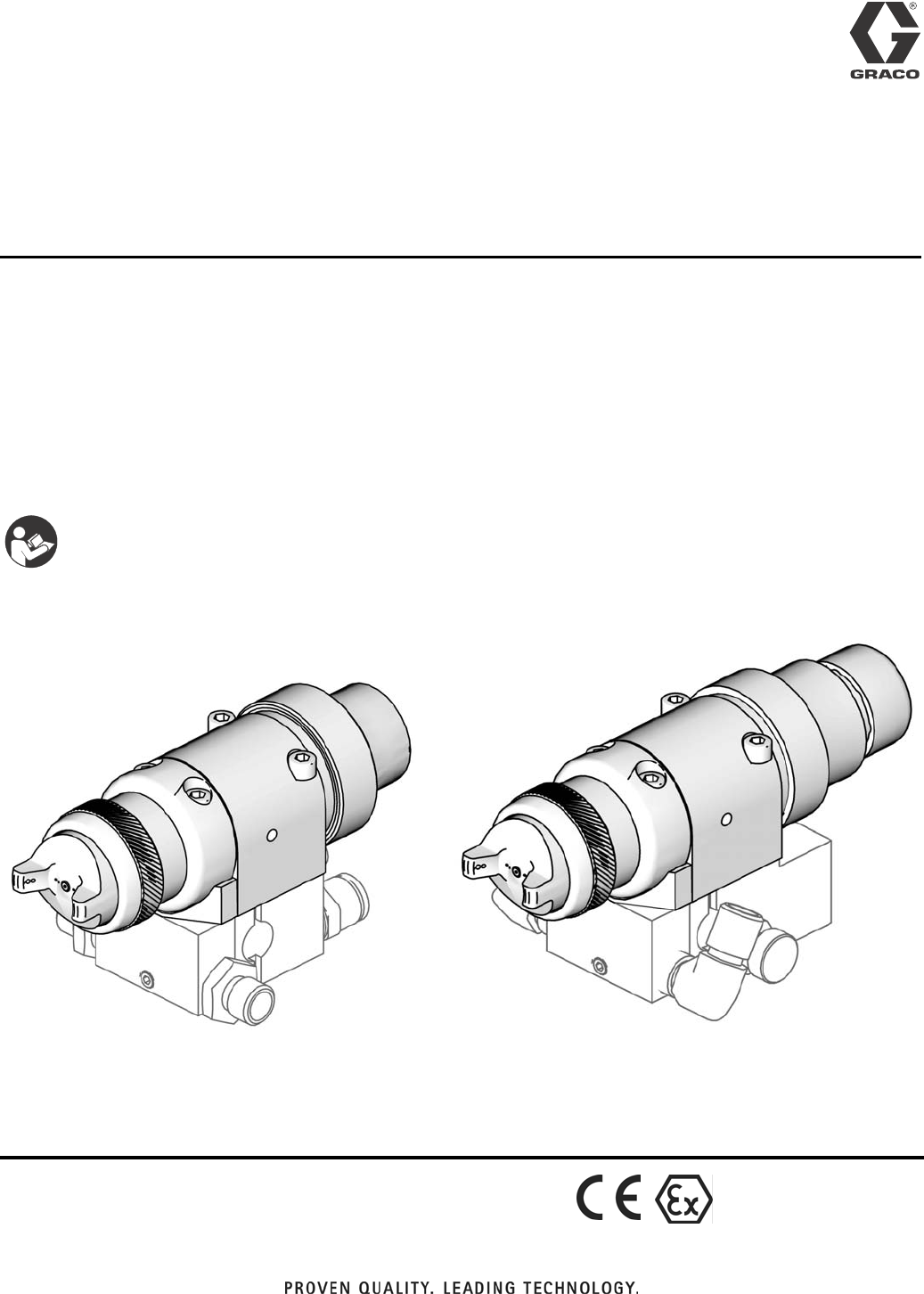
Part 24A749 Conventional Gun shown
mounted on Part 288217 Manifold. Part 24A753 Conventional Gun with fluid control
shown mounted on Part 288223 Manifold.
ti13585a ti13586a
II 2 G c IIB T6

Models
2313516G
Contents
Models . . . . . . . . . . . . . . . . . . . . . . . . . . . . . . . . . . . 2
Warnings . . . . . . . . . . . . . . . . . . . . . . . . . . . . . . . . . 3
Selection Charts . . . . . . . . . . . . . . . . . . . . . . . . . . . 5
Air Flow . . . . . . . . . . . . . . . . . . . . . . . . . . . . . . . . . . 8
Installation . . . . . . . . . . . . . . . . . . . . . . . . . . . . . . . 10
Setup . . . . . . . . . . . . . . . . . . . . . . . . . . . . . . . . . . . . 14
Operation . . . . . . . . . . . . . . . . . . . . . . . . . . . . . . . . 18
Troubleshooting . . . . . . . . . . . . . . . . . . . . . . . . . . . 21
Service . . . . . . . . . . . . . . . . . . . . . . . . . . . . . . . . . . 23
Parts . . . . . . . . . . . . . . . . . . . . . . . . . . . . . . . . . . . . 26
Repair Kits . . . . . . . . . . . . . . . . . . . . . . . . . . . . . . . 28
Accessories . . . . . . . . . . . . . . . . . . . . . . . . . . . . . . 34
Dimensions . . . . . . . . . . . . . . . . . . . . . . . . . . . . . . . 36
Mounting Hole Layouts . . . . . . . . . . . . . . . . . . . . . 38
Technical Data . . . . . . . . . . . . . . . . . . . . . . . . . . . . 43
Graco Standard Warranty . . . . . . . . . . . . . . . . . . . 44
Graco Information . . . . . . . . . . . . . . . . . . . . . . . . . 44
Models
NOTE: A manifold is required for each gun to be installed. Refer to the Parts section for manifold
information.
Application Orifice Size
in. (mm) Conventional HVLP Compliant
General Metal 0.020 (0.5) 24B333 24B334 24B335
General Metal 0.030 (0.8) 24A747 24A754 24A761
General Metal 0.042 (1.1) 24A748 24A755 24A762
General Metal 0.055 (1.4) 24A749 24A756 24A763
General Metal 0.070 (1.8) 24A750 24A757 24A764
General Metal with Fluid Control Knob 0.030 (0.8) 24A751 24A758 24A765
General Metal with Fluid Control Knob 0.042 (1.1) 24A752 24A759 24A766
General Metal with Fluid Control Knob 0.055 (1.4) 24A753 24A760 24A767
High Wear 0.059 (1.5) 24A774 24A776 24A778
High Wear 0.070 (1.8) 24A775 24A777 24A779
High Wear 0.086 (2.2) 24B336
High Wear 0.110 (2.8) 24C316
Wood 0.030 (0.8) 24A768 24A770 24A772
Wood 0.040 (1.0) 24A769 24A771 24A773
Warnings
313516G 3
Warnings
The following warnings are for the setup, use, grounding, maintenance, and repair of this equip-
ment. The exclamation point symbol alerts you to a general warning and the hazard symbol refers
to procedure-specific risk. Refer back to these warnings. Additional, product-specific warnings
may be found throughout the body of this manual where applicable.
FIRE AND EXPLOSION HAZARD
Flammable fumes, such as solvent and paint fumes, in work area can ignite or
explode. To help prevent fire and explosion:
• Use equipment only in well ventilated area.
• Eliminate all ignition sources; such as pilot lights, cigarettes, portable electric
lamps, and plastic drop cloths (potential static arc).
• Keep work area free of debris, including solvent, rags and gasoline.
• Do not plug or unplug power cords, or turn power or light switches on or off when
flammable fumes are present.
• Ground all equipment in the work area.
• Use only grounded hoses.
• Hold gun firmly to side of grounded pail when triggering into pail.
• If there is static sparking or you feel a shock, stop operation immediately. Do not
use equipment until you identify and correct the problem.
• Keep a working fire extinguisher in the work area.
EQUIPMENT MISUSE HAZARD
Misuse can cause death or serious injury.
• Do not operate the unit when fatigued or under the influence of drugs or alcohol.
• Do not exceed the maximum working pressure or temperature rating of the lowest
rated system component. See Technical Data in all equipment manuals.
• Do not leave the work area while equipment is energized or under pressure. Turn
off all equipment and follow the Pressure Relief Procedure in this manual when
equipment is not in use.
• Check equipment daily. Repair or replace worn or damaged parts immediately with
genuine manufacturer’s replacement parts only.
• Do not alter or modify equipment.
• Use equipment only for its intended purpose. Call your distributor for information.
• Route hoses and cables away from traffic areas, sharp edges, moving parts, and
hot surfaces.
• Do not kink or over bend hoses or use hoses to pull equipment.
• Keep children and animals away from work area.
• Comply with all applicable safety regulations.
WARNING
Warnings
4313516G
PRESSURIZED EQUIPMENT HAZARD
Fluid from the gun/dispense valve, leaks, or ruptured components can splash in the
eyes or on skin and cause serious injury.
• Follow Pressure Relief Procedure in this manual, when you stop spraying and
before cleaning, checking, or servicing equipment.
• Tighten all fluid connections before operating the equipment.
• Check hoses, tubes, and couplings daily. Replace worn or damaged parts immedi-
ately.
TOXIC FLUID OR FUMES HAZARD
Toxic fluids or fumes can cause serious injury or death if splashed in the eyes or on
skin, inhaled, or swallowed.
• Read MSDS’s to know the specific hazards of the fluids you are using.
• Store hazardous fluid in approved containers, and dispose of it according to appli-
cable guidelines.
• Always wear impervious gloves when spraying or cleaning equipment.
PERSONAL PROTECTIVE EQUIPMENT
You must wear appropriate protective equipment when operating, servicing, or when
in the operating area of the equipment to help protect you from serious injury, includ-
ing eye injury, inhalation of toxic fumes, burns, and hearing loss. This equipment
includes but is not limited to:
•Protective eyewear
• Clothing and respirator as recommended by the fluid and solvent manufacturer
•Gloves
• Hearing protection
WARNING

Selection Charts
313516G 5
Selection Charts
TERMS
Light Fluid: Up to 18 seconds with No. 2 Zahn
cup (20 centipoise)
Medium Fluid:19 to 28 seconds with No. 2
Zahn cup (20-64 centipoise)
Heavy Fluid: Greater than 28 seconds with
No. 2 Zahn cup (greater than 64 centipoise) --
2.8 Volatile Organic Compounds, High-solid
Polyurethanes, Heavy Waterborne Enamels
General Metal Applications
★With Fluid Control Knob (for fine adjustment of fluid flow).
Gun
Assembly
Part No. Type
Includes: Air Cap
Part No.
(without pin,
for reference)
Orifice
Size
in. (mm)
Material Usage
Needle/
Nozzle Kit
Part No.
Air Cap
with Pin
Part No. Viscosity Flow
oz./min. (l/min.)
24B333 Conventional 24B332 24B544 289773 0.020 (0.5) light 2–6 (0.06–0.18)
24A747 Conventional 24A687 24B544 289773 0.030 (0.8) light 4–10 (0.12–0.30)
24A748 Conventional 24A688 24B544 289773 0.042 (1.1) light-medium 8–14 (0.24–0.42)
24A749 Conventional 24A689 24B544 289773 0.055 (1.4) medium 12–18 (0.36–0.54)
24A750 Conventional 24A690 24B545 289784 0.070 (1.8) medium-heavy 16–20 (0.48–0.60)
24B334 HVLP 24B332 24B539 289041 0.020 (0.5) light 2–6 (0.06–0.18)
24A754 HVLP 24A687 24B539 289041 0.030 (0.8) light 4–10 (0.12–0.30)
24A755 HVLP 24A688 24B539 289041 0.042 (1.1) light-medium 8–14 (0.24–0.42)
24A756 HVLP 24A689 24B539 289041 0.055 (1.4) medium 12–18 (0.36–0.54)
24A757 HVLP 24A690 24B539 289041 0.070 (1.8) medium-heavy 16–20 (0.48–0.60)
24B335 Compliant 24B332 24B540 289042 0.020 (0.5) light 2–6 (0.06–0.18)
24A761 Compliant 24A687 24B540 289042 0.030 (0.8) light 4–10 (0.12–0.30)
24A762 Compliant 24A688 24B540 289042 0.042 (1.1) light-medium 8–14 (0.24–0.42)
24A763 Compliant 24A689 24B540 289042 0.055 (1.4) medium 12–18 (0.36–0.54)
24A764 Compliant 24A690 24B540 289042 0.070 (1.8) medium-heavy 16–20 (0.48–0.60)
24A751★Conventional 24A687 24B544 289773 0.030 (0.8) light 4–10 (0.12–0.30)
24A752★Conventional 24A688 24B544 289773 0.042 (1.1) light-medium 8–14 (0.24–0.42)
24A753★Conventional 24A689 24B544 289773 0.055 (1.4) medium 12–18 (0.36–0.54)
24A758★HVLP 24A687 24B539 289041 0.030 (0.8) light 4–10 (0.12–0.30)
24A759★HVLP 24A688 24B539 289041 0.042 (1.1) light-medium 8–14 (0.24–0.42)
24A760★HVLP 24A689 24B539 289041 0.055 (1.4) medium 12–18 (0.36–0.54)
24A765★Compliant 24A687 24B540 289042 0.030 (0.8) light 4–10 (0.12–0.30)
24A766★Compliant 24A688 24B540 289042 0.042 (1.1) light-medium 8–14 (0.24–0.42)
24A767★Compliant 24A689 24B540 289042 0.055 (1.4) medium 12–18 (0.36–0.54)

Selection Charts
6313516G
High Wear Applications
✠ Needle tip and nozzle exit constructed from tungsten carbide.
Wood Applications
Gun Selection
HVLP Guns
An HVLP gun is a high transfer efficiency gun
that limits the air pressure at the air cap to
10 psi (0.07 MPa, 0.7 bar) maximum. In some
areas, an HVLP gun is required for compliance
with environmental standards. See the Air Cap
chart, page 7, for maximum inlet pressures.
Compliant Guns
A compliant gun is a high transfer efficiency
gun that has been tested to have a transfer
efficiency greater than or equal to HVLP guns.
In addition, the compliant air cap consumes
much less air than the HVLP air cap. Graco
compliant guns have no restrictions on air cap
pressures. See the Air Cap chart, page 7, for
maximum inlet pressures.
Gun
Assembly
Part No. Type
Includes: Air Cap
Part No.
(without pin,
for reference)
Orifice
Size
in. (mm)
Material Usage
Needle/
Nozzle Kit
Part No.
Air Cap
with Pin
Part No. Viscosity Flow
oz./min. (l/min.)
24A774✠Conventional 24A693 24B537 288861 0.059 (1.5) medium 12–18 (0.36–0.54)
24A775✠Conventional 24A694 24B536 289049 0.070 (1.8) medium-heavy 16–20 (0.48–0.60)
24B336✠Conventional 24B358 24B536 289049 0.086 (2.2) heavy >20 (>0.60)
24C316✠Conventional 24C142 24B536 289049 0.110 (2.8) heavy >25 (>0.74)
24A776✠HVLP 24A695 24B541 289115 0.059 (1.5) medium 12–18 (0.36–0.54)
24A777✠HVLP 24A696 24B542 289325 0.070 (1.8) medium-heavy 16–20 (0.48–0.60)
24A778✠Compliant 24A695 24B538 289050 0.059 (1.5) medium 12–18 (0.36–0.54)
24A779✠Compliant 24A696 24B543 289327 0.070 (1.8) medium-heavy 16–20 (0.48–0.60)
Gun
Assembly
Part No. Type
Includes: Air Cap
Part No.
(without pin,
for reference)
Orifice
Size
in. (mm)
Material Usage
Needle/
Nozzle Kit
Part No.
Air Cap
with Pin
Part No. Viscosity Flow
oz./min. (l/min.)
24A768 Conventional 24A691 24B533 288862 0.030 (0.8) light 4–10 (0.12–0.30)
24A769 Conventional 24A692 24B533 288862 0.040 (1.0) light-medium 8–14 (0.24–0.42)
24A770 HVLP 24A691 24B535 288864 0.030 (0.8) light 4–10 (0.12–0.30)
24A771 HVLP 24A692 24B535 288864 0.040 (1.0) light-medium 8–14 (0.24–0.42)
24A772 Compliant 24A691 24B534 288863 0.030 (0.8) light 4–10 (0.12–0.30)
24A773 Compliant 24A692 24B534 288863 0.040 (1.0) light-medium 8–14 (0.24–0.42)

Selection Charts
313516G 7
Conventional Guns
An airspray gun has excellent atomization and
high production rates typically with some
reduction in transfer efficiency.
Proper Needle/Nozzle Selection
The spray gun's needle/nozzle kits range in
size to provide different fluid flow rates. As a
general guideline, use the fluid nozzle that will
give the required flow with the needle fully trig-
gered at a fluid pressure of 5–20 psi
(0.035–0.14 MPa, 0.35–1.4 bar).
• For low flow rates or light viscosity fluid,
select the smaller nozzle sizes.
• For high flow rates or high viscosity fluid,
select the larger nozzle sizes.
• For abrasive fluids, the high wear gun mod-
els are recommended.
Air Caps
Air Cap
Part
No. Type Application
Nozzle
Orifice
in. (mm)
Atomizing Air
Max. HVLP/Compliant
Manifold Inlet Pressure
psi (MPa, bar)
Fan Air
Max. HVLP/Compliant
Manifold Inlet Pressure
psi (MPa, bar)
289773 Conventional General Metal
0.020–0.055
(0.5–1.4) N/A N/A
289784 Conventional General Metal 0.070 (1.8) N/A N/A
289041 HVLP General Metal
0.020–0.070
(0.5–1.8) 17 (0.12, 1.2) 29 (0.20, 2.0)
289042 Compliant General Metal
0.020–0.070
(0.5–1.8) 29 (0.20, 2.0) 33 (0.23, 2.3)
288861 Conventional High Wear 0.059 (1.5) N/A N/A
289049 Conventional High Wear
0.070–0.086
(1.8–2.2) N/A N/A
289115 HVLP High Wear 0.059 (1.5) 18 (0.12, 1.2) 28 (0.19, 1.9)
289325 HVLP High Wear 0.070 (1.8) 18 (0.12, 1.2) 27 (0.19, 1.9)
289050 Compliant High Wear 0.059 (1.5) 28 (0.19, 1.9) 31 (0.21, 2.1)
289327 Compliant High Wear 0.070 (1.8) 29 (0.20, 2.0) 32 (0.22, 2.2)
288862 Conventional Wood
0.030–0.040
(0.8–1.0) N/A N/A
288864 HVLP Wood
0.030–0.040
(0.8–1.0) 24 (0.17, 1.7) 26 (0.18, 1.8)
288863 Compliant Wood
0.030–0.040
(0.8–1.0) 27 (0.19, 1.9) 42 (0.29, 2.9)

Air Flow
8313516G
Air Flow
See the chart to determine air consumption. Add the air consumption values shown for the atom-
izing air and fan air pressures to get the total air consumption. For example, air cap 24B544 with
20 psi atomizing air pressure uses 3 scfm atomizing air. A 30 psi fan inlet pressure adds 5 scfm
fan air for a total of 8 scfm air consumption.
Air cap
Atomizing Air Fan Air
Manifold Inlet Pressure
psi (MPa, bar)
Air Flow
SCFM
Manifold Inlet Pressure
psi (MPa, bar)
Air Flow
SCFM
289773
10 (0.07, 0.7) 2 10 (0.07, 0.7) 2
20 (0.14, 1.4) 3 20 (0.14, 1.4) 4
30 (0.21, 2.1) 5 30 (0.21, 2.1) 5
40 (0.28, 2.8) 7 40 (0.28, 2.8) 7
50 (0.34, 3.4) 8 50 (0.34, 3.4) 9
289041
10 (0.07, 0.7) 3 10 (0.07, 0.7) 4
20 (0.14, 1.4) 7 20 (0.14, 1.4) 7
30 (0.21, 2.1) 10 30 (0.21, 2.1) 11
40 (0.28, 2.8) 13 40 (0.28, 2.8) 14
50 (0.34, 3.4) 17 50 (0.34, 3.4) 18
17* (0.12, 1.2) 6 29* (0.20, 2.0) 10
288861
10 (0.07, 0.7) 2 10 (0.07, 0.7) 2
20 (0.14, 1.4) 4 20 (0.14, 1.4) 5
30 (0.21, 2.1) 6 30 (0.21, 2.1) 7
40 (0.28, 2.8) 8 40 (0.28, 2.8) 10
50 (0.34, 3.4) 11 50 (0.34, 3.4) 12
289115
10 (0.07, 0.7) 3 10 (0.07, 0.7) 4
20 (0.14, 1.4) 7 20 (0.14, 1.4) 7
30 (0.21, 2.1) 10 30 (0.21, 2.1) 11
40 (0.28, 2.8) 14 40 (0.28, 2.8) 15
50 (0.34, 3.4) 17 50 (0.34, 3.4) 19
18* (0.12, 1.2) 6 28* (0.19, 1.9) 10
289050
10 (0.07, 0.7) 1 10 (0.07, 0.7) 2
20 (0.14, 1.4) 3 20 (0.14, 1.4) 4
30 (0.21, 2.1) 4 30 (0.21, 2.1) 6
40 (0.28, 2.8) 5 40 (0.28, 2.8) 8
50 (0.34, 3.4) 7 50 (0.34, 3.4) 10
28* (0.19, 1.9) 4 31* (0.21, 2.1) 6
288862
10 (0.07, 0.7) 2 5 (0.035, 0.35) 1
20 (0.14, 1.4) 4 10 (0.07, 0.7) 3
30 (0.21, 2.1) 6 15 (0.10, 1.0) 4
40 (0.28, 2.8) 7 20 (0.14, 1.4) 5
50 (0.34, 3.4) 9 25 (0.17, 1.7) 7

Air Flow
313516G 9
* Maximum HVLP/Compliant inlet manifold pressure.
288863
10 (0.07, 0.7) 2 10 (0.07, 0.7) 3
20 (0.14, 1.4) 4 20 (0.14, 1.4) 5
30 (0.21, 2.1) 5 30 (0.21, 2.1) 8
40 (0.28, 2.8) 7 40 (0.28, 2.8) 11
50 (0.34, 3.4) 9 50 (0.34, 3.4) 13
27* (0.19, 1.9) 5 42* (0.29, 2.9) 11
289784
10 (0.07, 0.7) 2 10 (0.07, 0.7) 2
20 (0.14, 1.4) 4 20 (0.14, 1.4) 4
30 (0.21, 2.1) 6 30 (0.21, 2.1) 5
40 (0.28, 2.8) 8 40 (0.28, 2.8) 7
50 (0.34, 3.4) 10 50 (0.34, 3.4) 9
289042
10 (0.07, 0.7) 2 10 (0.07, 0.7) 2
20 (0.14, 1.4) 4 20 (0.14, 1.4) 4
30 (0.21, 2.1) 6 30 (0.21, 2.1) 6
40 (0.28, 2.8) 8 40 (0.28, 2.8) 8
50 (0.34, 3.4) 10 50 (0.34, 3.4) 10
29* (0.20, 2.0) 6 33* (0.23, 2.3) 7
289049
10 (0.07, 0.7) 1 10 (0.07, 0.7) 2
20 (0.14, 1.4) 3 20 (0.14, 1.4) 4
30 (0.21, 2.1) 4 30 (0.21, 2.1) 7
40 (0.28, 2.8) 6 40 (0.28, 2.8) 9
50 (0.34, 3.4) 7 50 (0.34, 3.4) 11
289325
10 (0.07, 0.7) 4 10 (0.07, 0.7) 4
20 (0.14, 1.4) 7 20 (0.14, 1.4) 7
30 (0.21, 2.1) 11 30 (0.21, 2.1) 11
40 (0.28, 2.8) 14 40 (0.28, 2.8) 14
50 (0.34, 3.4) 18 50 (0.34, 3.4) 18
18* (0.12, 1.2) 6 27* (0.19, 1.9) 10
289327
10 (0.07, 0.7) 2 10 (0.07, 0.7) 2
20 (0.14, 1.4) 4 20 (0.14, 1.4) 4
30 (0.21, 2.1) 6 30 (0.21, 2.1) 6
40 (0.28, 2.8) 7 40 (0.28, 2.8) 8
50 (0.34, 3.4) 9 50 (0.34, 3.4) 10
29* (0.20, 2.0) 5 32* (0.22, 2.2) 7
288864
10 (0.07, 0.7) 4 10 (0.07, 0.7) 3
20 (0.14, 1.4) 7 20 (0.14, 1.4) 6
30 (0.21, 2.1) 11 30 (0.21, 2.1) 10
40 (0.28, 2.8) 14 40 (0.28, 2.8) 13
50 (0.34, 3.4) 18 50 (0.34, 3.4) 16
24* (0.17, 1.7) 9 26* (0.18, 1.8) 8
Air cap
Atomizing Air Fan Air
Manifold Inlet Pressure
psi (MPa, bar)
Air Flow
SCFM
Manifold Inlet Pressure
psi (MPa, bar)
Air Flow
SCFM
Installation
10 313516G
Installation
The Automatic AirPro spray gun can spray
most coatings or finishes currently being used
for automotive, industrial, aerospace, marine,
wood, plastic and architectural applications,
while easily operating from paint delivery sys-
tems, such as pressure pots or remote pumps
for production line operation.
The air regulator must have a minimum air flow
capacity of 30 scfm at 100 psi (0.7 MPa, 7.0
bar) air pressure.
Ventilate Spray Booth
• Check and follow all national, state, and
local codes regarding air exhaust velocity
requirements.
• Check and follow all local safety and fire
codes.
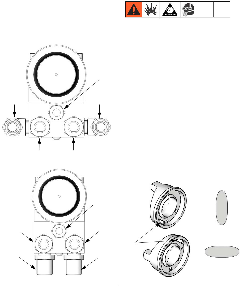
Configure Gun and Manifold
The gun is supplied with an internal fluid plug
and seals (19, 20, 21). To use the gun in a cir-
culating system, remove the internal plug. In a
non-circulating system, leave the plug in place
to minimize flush time.
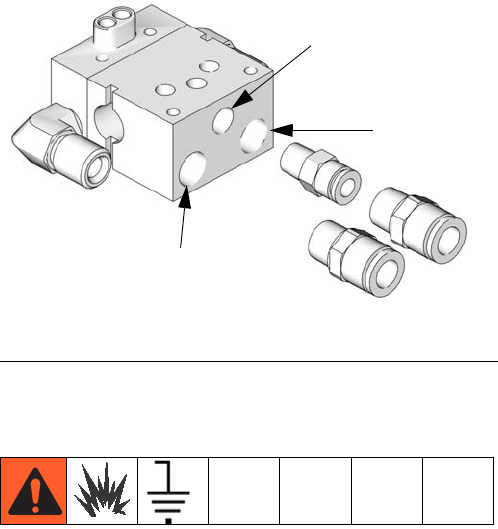
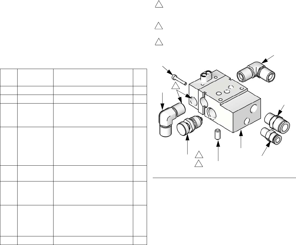
Circulating System
1. Apply anti-seize lubricant to the threads
and mating faces of the manifold (101) and
the elbows (107), supplied unassembled.
2. Install the elbows (107) in both fluid ports of
the manifold (101).
3. Connect the fluid supply line to one elbow
and the fluid return line to the other. The
manifold fluid ports are reversible.
4. Install the gun on the manifold, using the
four screws (13). Start the threads of all
four screws. Tighten the front two screws
first, and then tighten the back two. Torque
all four screws evenly to 65 in-lb (7.3 N•m).
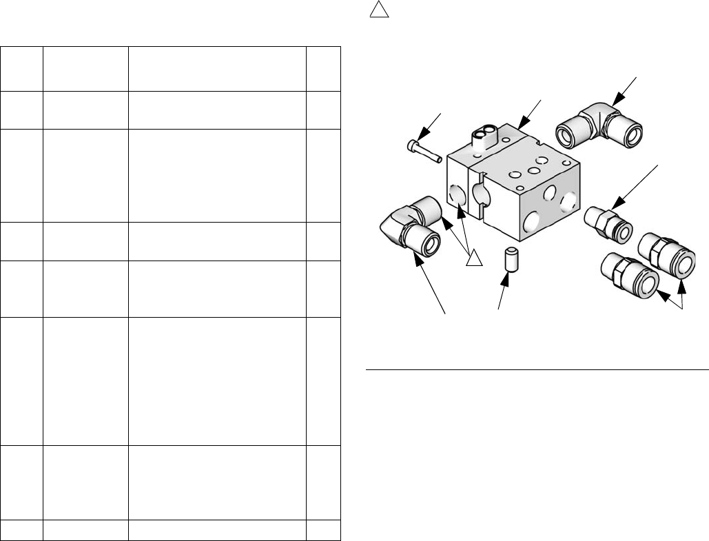
Non-circulating System
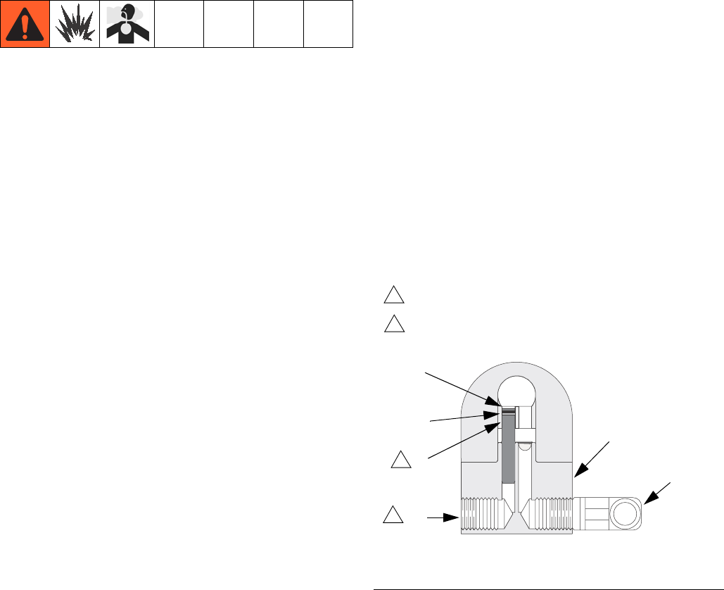
1. See FIG. 1. Apply anti-seize lubricant to the
threads and mating faces of the manifold
(101), plug (109), and elbow (107), sup-
plied unassembled.
2. Install an elbow (107) in one fluid port of
the manifold (101), and a plug (109) in the
other port.
3. Install the internal plug (19) in the gun fluid
port on the same side as the manifold plug.
4. Connect the fluid supply line to the fluid
inlet elbow (107).
5. Install the gun on the manifold, using the
four screws supplied. Start the threads of
all four screws. Tighten the front two
screws first, and then tighten the back two.
Torque all four screws evenly to 65 in-lb
(7.3 N•m).
FIG. 1: Non-Circulating Setup Shown (cutaway view)
Remove when used in circulating systems.
1
ti8587b
1
Replace with elbow (107) when used in
circulating systems.
2
2
19
101
107
109
21
20
Installation
313516G 11
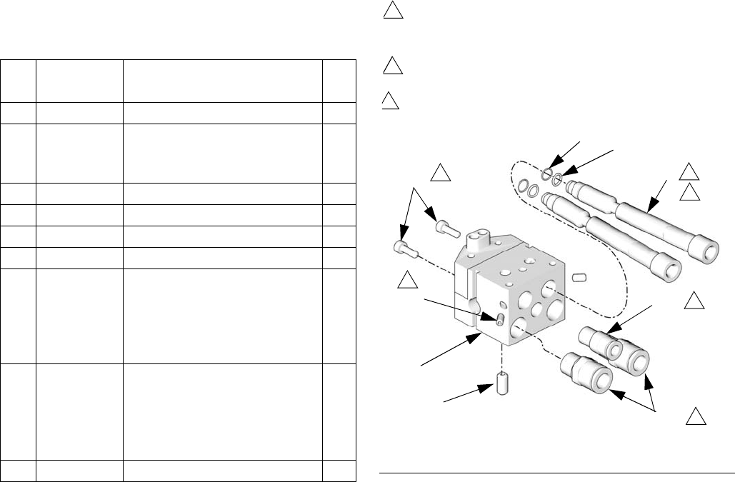
Install Air Fittings
1. Install the supplied 1/4 in. tube fitting into
the cylinder (CYL) air port.
2. Install 3/8 in. tube fittings into the atomiza-
tion (ATOM) air port and the fan (FAN) air
port.
Ground System
The following grounding instructions are mini-
mum requirements for a system. Your system
may include other equipment or objects that
must be grounded. Check your local electrical
code for detailed grounding instructions for
your area and type of equipment. Your system
must be connected to a true earth ground.
Ground Pump/Fluid Supply
Ground the pump by connecting a ground wire
and clamp between the fluid supply and a true
earth ground as instructed in your separate
pump instruction manual.
Ground Air Compressors and
Hydraulic Power Supplies
Ground the air compressors and hydraulic
power supplies according to the manufacturer
recommendations.
Ground Spray Gun
Ground the spray gun by mounting the mani-
fold to a properly grounded reciprocator, robot,
or stationary mount. Check the electrical resis-
tance between the manifold and a true earth
ground. The resistance must be less than 1
megohm.
Ground Fluid Supply Container
Ground the fluid supply container according to
local code.
Ground Object Being Sprayed
Ground the object that is being sprayed
according to local code.
Ground Solvent Pails
Ground all solvent pails that are used when
flushing according to local code. Use only
metal pails, which are conductive. Do not place
the pail on a non-conductive surface, such as
paper or cardboard, which interrupts the
grounding continuity.
FIG. 2: Air Fittings
CYL
ATOM
FAN
ti8211a
Installation
12 313516G
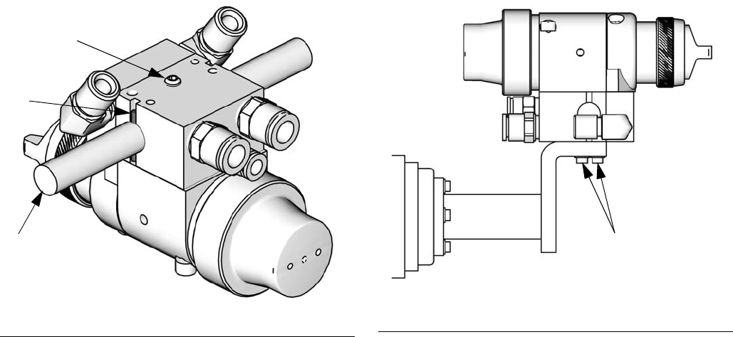
Mount Gun
Reciprocating Arm Rod Mount
To mount the gun on a reciprocating arm rod
[0.5 in. (13 mm) diameter maximum]:
1. Insert the mounting bar (A) through the
hole in the manifold as shown in FIG. 3.
NOTE: Use the 1/8 in. alignment pin (P) to
assist in orienting the gun.
2. Secure the gun to the bar by tightening the
mounting screw (B).
Stationary Support
To mount the gun on a stationary support
(refer to FIG. 4 and to the correct mounting
hole layout for your manifold, pages 38-42):
1. Align the manifold with the alignment pins.
Locate alignment pins and holes per the
mounting hole layout.
2. Secure the gun to the support with two M5
x 0.8 capscrews (C). The screws must be
long enough to engage the threaded holes
in the gun manifold to a depth of 1/4 in.
(6 mm).
FIG. 3: Reciprocating Arm Mount
B
P
A
ti13587a FIG. 4: Stationary Support Mount
C
ti13588a
Installation
313516G 13
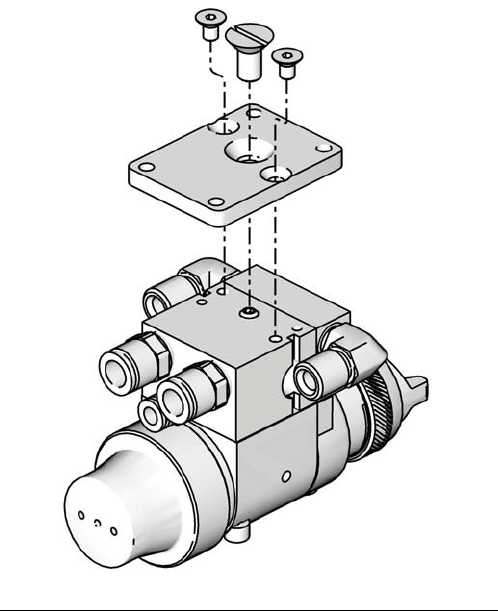
Retrofit Adapter Plate
The retrofit adapter plate enables the manifold
to be attached to a variety of bolt patterns.
To mount the gun using the retrofit adapter
plate (Kit 288197; See Accessories,
page 34):
1. Mount adapter plate to manifold using the
three screws provided with the kit. (See
FIG. 5 and the mounting hole layout on
page 42.)
2. Bolt plate to mounting surface using four
M5 x 0.8 capscrews. Refer to the correct
mounting hole layout for your manifold,
pages 38-41.
FIG. 5: Retrofit Adapter Plate Mount
ti13589a
Setup
14 313516G
Setup
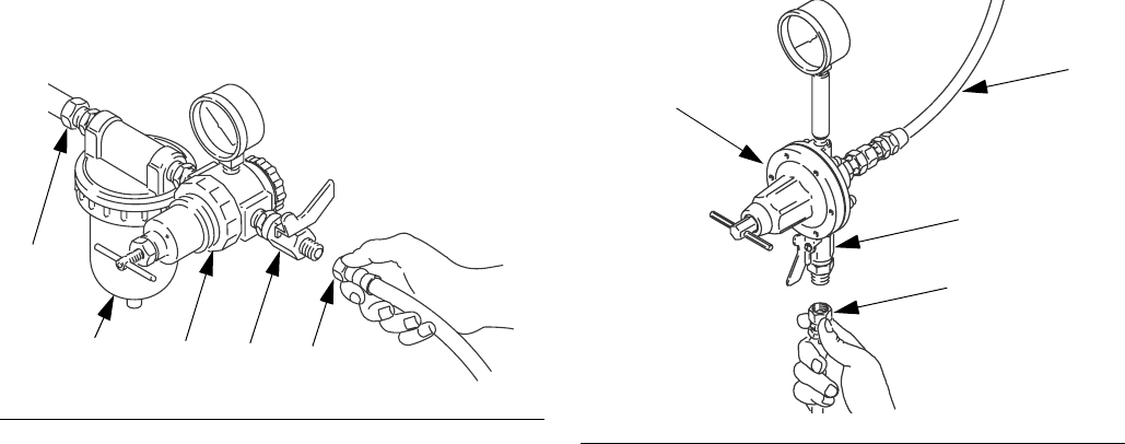
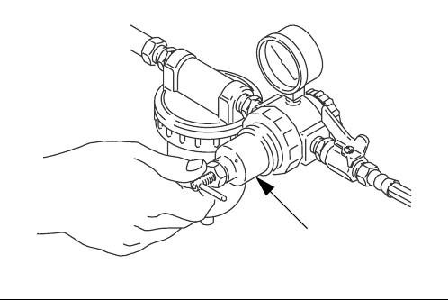
Connect Air Line
NOTE:
• You must install an air pressure regula-
tor (F) on each gun air line to control air
pressure to the gun. See FIG. 6.
• If your regulated air source does not
have a filter, install an air filter (G) on
each air line to ensure a dry, clean air
supply to the gun. Dirt and moisture can
ruin the appearance of your finished
workpiece. See FIG. 6.
• Install a bleed type air shutoff valve (E)
on each gun air supply line, down-
stream of the gun air regulator, to shut
off air to the gun.
1. For manifolds with a separate ATOM and
FAN port, the gun cylinder, fan, and atomi-
zation air must be supplied and regulated
separately. For the manual fan valve mani-
fold, only one supply line is required for
both atomization and fan air.
NOTE: The gun atomizing and fan air inlets
are 3/8 in. O.D. tubing. The cylinder air inlet
accepts 1/4 in. (6.3 mm) O.D. tubing. Use 3/8
in. (9.5 mm) O.D. tubing for fan and atomiza-
tion air to minimize excessive pressure drop in
the hoses.
2. Connect each air hose (D) to a regulated
air supply line (H).
Connect Fluid Hose
NOTE:
• Before connecting the fluid line, blow it
out with air and flush it with solvent. Use
solvent that is compatible with the fluid
to be sprayed.
• Install a fluid regulator (L) on the fluid
line to control fluid pressure to the gun.
• Install a fluid shutoff valve (M) to shut off
the fluid supply to the gun.
• Filter the fluid line of coarse particles
and sediment to avoid clogging the fluid
nozzle and causing finishing defects.
Inline fluid filter 24B707 is available.
See Accessories, page 34.
1. Connect the fluid supply hose (J) to the gun
fluid inlet (S), 1/4 npsm thread. See FIG. 8.
2. Connect the other end of the fluid hose (J)
to a regulated fluid supply outlet (M).
3. In a circulating system, connect a
grounded fluid return hose to the gun fluid
outlet (T). See FIG. 8.
In a non-circulating system, remove the
gun fluid outlet fitting (T) and plug the outlet
port with the pipe plug supplied. See FIG. 8.
FIG. 6: Connect Air Line
ti01990
H
GFED
FIG. 7: Connect Fluid Hose.
M
L
K
J
ti7016a
Setup
313516G 15
Flush Spray Gun
Before running any paint through the spray
gun:
1. Flush the gun with a solvent that is compat-
ible with the fluid to be sprayed, using the
lowest possible fluid pressure and a
grounded metal container.
2. Perform Pressure Relief Procedure; see
page 18.
Position Air Cap
Air caps are factory-set with the alignment pin
(A) set to a vertical spray pattern. To change
the air cap to a horizontal spray pattern, use a
1/6 in. hex wrench to unscrew the alignment
pin (A) and relocate it to the horizontal spray
pattern hole. When relocating the pin use low
strength thread locker. Torque to 1.5-2.5 in-lb
(0.2-0.3 N•m). Do not overtighten. Refer to
FIG. 9.
FIG. 8: Manifold Ports
FAN ATOM
CYL
KEY
N Cylinder Air Inlet: accepts 1/4 in. (6.3 mm) O.D. tubing
P Atomization Air Inlet: 3/8 in, (9.5 mm) O.D. tubing
R Fan Air Inlet: 3/8 in. (9.5 mm) O.D. tubing
S Fluid Inlet: 1/4 npsm
T Fluid Outlet (circulating gun only): 1/4 npsm
N
S (or T)T (or S)
RP
N
S (or T)
T (or S)
RP
ti8096a
ti8097a
Side Mounted Manifold Ports
Bottom Mounted Manifold Ports
FAN ATOM
CYL
FIG. 9: Position Air Cap
Vertical Pattern
Horizontal Pattern
ti8171a
ti8170a
A
ti8172a
Setup
16 313516G
Adjust Spray Pattern
Use the fluid pressure regulator to adjust the
spray gun fluid flow. Some models are
equipped with a fluid control knob to make pre-
cise fluid flow adjustments.
Follow these steps to establish the correct fluid
flow and air flow:
1. To achieve desired flow, adjust the fluid flow
using the fluid pressure regulator (L)
installed in the gun fluid line. Typical indus-
trial flow rates will vary with regulator pres-
sures from 5 to 30 psi (34 to 210 kPa, 0.3 to
2.1 bar). If the fluid pressure is too low at
the desired flow rate, install a smaller noz-
zle. If the fluid pressure is too high, install a
larger nozzle.
For spray guns equipped with the fluid con-
trol knob, you can make flow rate changes
at the spray gun. Rotate the fluid control
knob clockwise to reduce the flow.
NOTE: A larger fluid nozzle at a reduced fluid
pressure will maintain the same flow rate, but
the fluid stream (velocity) will slow down.
When air is applied, the lower velocity allows
the air to act on the fluid longer, which
improves atomization.
2. Using the air pressure regulator (F), set the
fan and atomizing air supply pressure per
Table 1. Use these suggested settings as a
starting point.
Do not exceed 100 psi (0.7 MPa, 7 bar)
maximum fluid and air pressure. Higher
pressures can cause parts to rupture and
result in serious injury.
NOTICE
Use caution when operating the fluid con-
trol knob near the closed position. The
plastic needle tip may be damaged if
forced too hard against the nozzle seat by
the fluid control knob.
FIG. 10: Fluid Pressure Regulator
Table 1: Suggested Starting Settings
Spray Gun Fan Air (psi) Atomization
Air (psi)
Conventional 35 35
HVLP 25 25
Compliant 25 25
L
ti7019a
Setup
313516G 17
NOTE: HVLP and Compliant Gun Limits
HVLP Guns: local laws may limit the maximum
pressure to 10 psi (70 kPa, 0.7 bar) at the air
cap for compliance. See the table on page 7
for maximum HVLP/Compliant manifold inlet
pressures. To measure pressure at the air cap,
use the appropriate HVLP Pressure Verifica-
tion Kit. See Accessories, page 34.
Compliant Guns: See the table on page 7 for
maximum HVLP/Compliant manifold inlet pres-
sures.
3. Test the spray pattern atomization while
keeping the gun a consistent distance,
about 6 to 8 inches (150 to 200 mm), from
the test piece.
Check the atomization quality. Increase the
gun atomizing air supply pressure with the
air pressure regulator in 5 psi (34 kPa, 0.3
bar) increments until you obtain the desired
atomization.
NOTE: For the best transfer efficiency, use the
lowest setting needed to achieve desired finish
quality.
4. If the spray pattern is too wide or split,
reduce the fan air pressure (or slightly
close the fan adjustment valve on manifold
288223).
To further control the spray pattern of air-
spray guns only, use an alternate air cap.
For a list of available air caps, refer to
Accessories, page 34.
NOTE: Reducing the fan air pressure to 0 psi
(or fully closing the fan adjustment valve) will
produce a round pattern.
FIG. 11: Air Pressure Regulator
Fti01997
Operation
18 313516G
Operation
Pressure Relief Procedure
1. Turn off all bleed type air valves and all
other air and fluid supplies to the gun.
2. Trigger the gun into a grounded metal
waste container to relieve air and fluid pres-
sure.
Apply Fluid
The spray gun has a built-in lead and lag oper-
ation. When triggered, the gun begins emitting
air before the fluid is discharged. When the
trigger actuation air is stopped, the fluid stops
before the air flow stops. This helps ensure
that the spray is atomized and prevents fluid
buildup on the air cap and tip.
Adjust the system control device, if it is auto-
matic, so the gun starts spraying just before
meeting the part and stops as soon as the part
has passed.
To achieve best results when applying fluid:
• Keep gun perpendicular and 6 to 8 in.
(150 to 200 mm) from object being
sprayed.
• Use smooth, parallel strokes across sur-
face to be sprayed with 50% overlap.
FIG. 12: Pressure Relief ti8174a
FIG. 13: Correct Spray Method
ti8098a
ti8099a
Correct
Incorrect
Operation
313516G 19
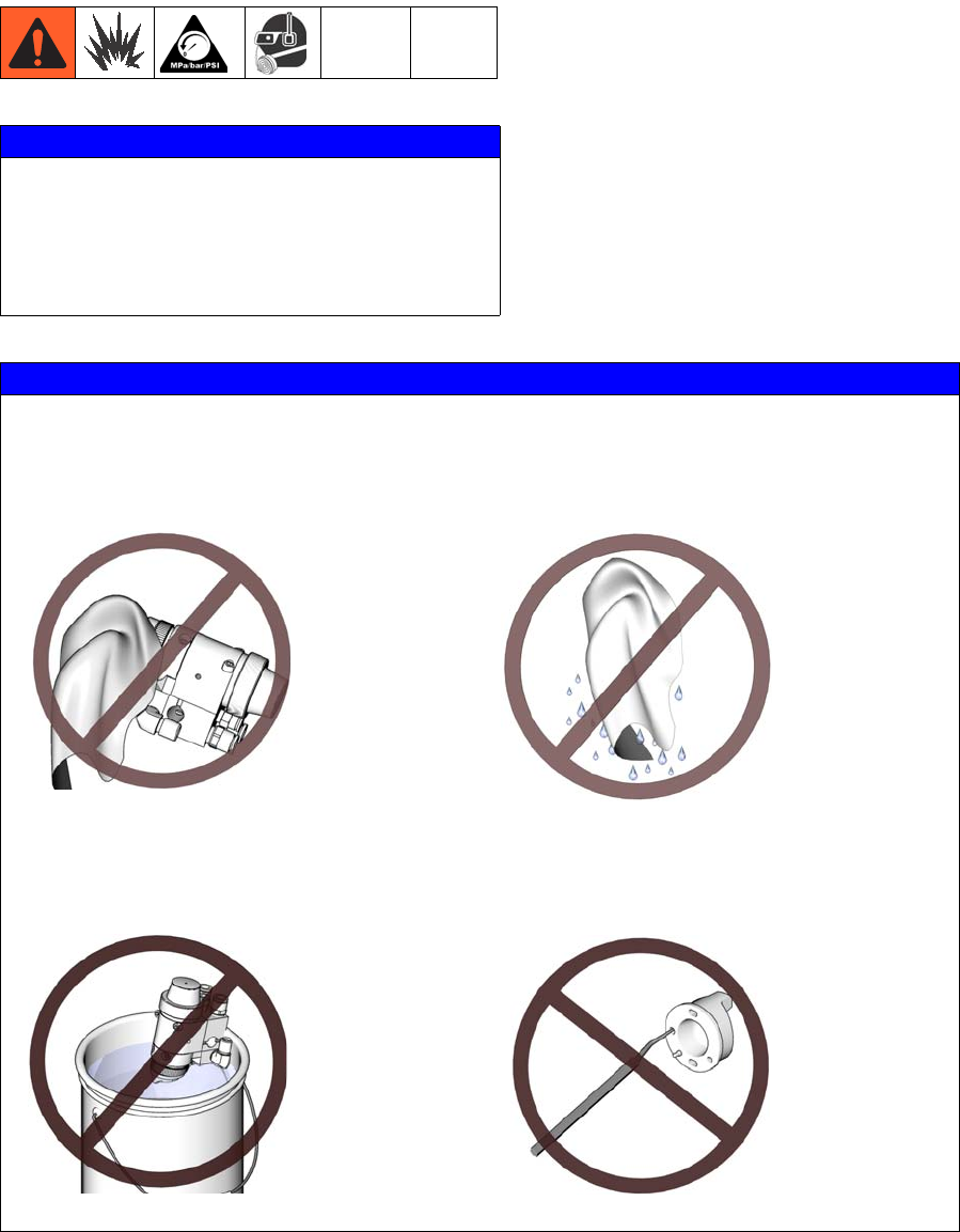
Daily Gun Care
NOTICE
Methylene chloride with formic or propi-
onic acid is not recommended as a flush-
ing or cleaning solvent with this gun as it
will damage aluminum and nylon compo-
nents.
NOTICE
Solvent left in gun air passages could result in a poor quality paint finish. Do not
use any cleaning method which may allow solvent into the gun air passages.
Do not point the gun up while cleaning it.
Do not immerse the gun in solvent.
Do not wipe the gun with a cloth soaked
in solvent; wring out the excess.
Do not use metal tools to clean the air
cap holes as this may scratch them;
scratches can distort the spray pattern.
ti8100a
ti8101a
ti4827a
ti8175a
Operation
20 313516G
General System Maintenance
•Perform Pressure Relief Procedure,
page 18.
• Clean the fluid and air line filters daily.
• Check for any fluid leakage from the gun
and fluid hoses. Tighten fittings or replace
equipment as needed.
• Flush the gun before changing colors and
whenever you are done operating the gun.
Clean and Flush Gun
1. Perform Pressure Relief Procedure,
page 18.
2. Shut off the gun fan and atomizing air.
3. Supply a compatible solvent to the gun fluid
inlet.
4. Point the gun down into a grounded metal
container, and flush the gun with solvent
until all traces of paint are removed from
the gun passages.
5. Perform Pressure Relief Procedure,
page 18.
6. Disconnect the solvent supply.
7. Remove the air cap retaining ring and air
cap. Remove the nozzle, if necessary.
8. Clean the air cap retaining ring, air cap,
and fluid nozzle with solvent.
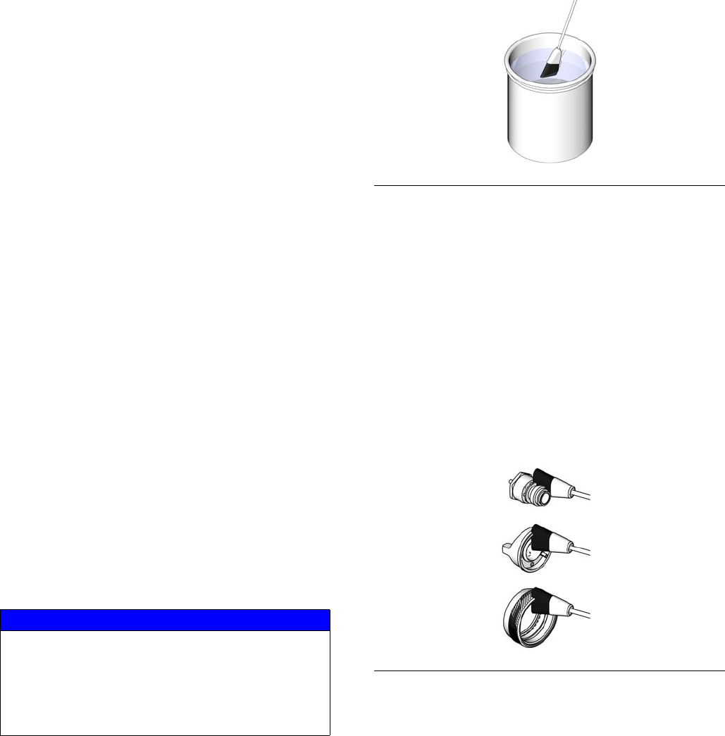
9. Dip the end of a soft-bristle brush into a
compatible solvent. Do not continuously
soak the brush's bristles with solvent and
do not use a wire brush.
10.With the gun pointed down, clean the front
of the gun, using the soft-bristle brush and
solvent.
11.Scrub the air cap retaining ring, air cap,
and fluid nozzle with the soft-bristle brush
(see FIG. 15). To clean out air cap holes,
use a soft implement, such as a toothpick,
to avoid damaging critical surfaces. Clean
the air cap and fluid nozzle daily, minimum.
Some applications require more frequent
cleaning.
12.Install the air cap retaining ring and air cap.
13.Dampen a soft cloth with solvent and wring
out the excess. Point the gun down and
wipe off the outside of the gun.
NOTICE
Trigger the gun or remove the piston cap if
you remove the nozzle for cleaning. This
keeps the needle seat away from the noz-
zle seating surface and prevents the seat
from being damaged.
FIG. 14: Use solvent-dipped soft-bristle brush
FIG. 15: Clean air cap, ring and fluid nozzle
ti4845a
ti8176a
Troubleshooting
313516G 21
Troubleshooting
NOTE: Check all possible remedies in the trou-
bleshooting charts before disassembling the
gun.
Some improper patterns are caused by the
improper balance between air and fluid. Refer
to Spray Pattern Troubleshooting, page 22.
General Troubleshooting
Problem Cause Solution
Fluid leakage through venting
holes.
Worn packing (17) or needle (5). Replace packing or needle.
Air leakage through venting hole. Worn o-ring (9) or gasket (15). Check and replace parts as
needed.
Air leakage from back of gun. Worn o-rings (8, 9). Replace o-rings.
Air does not trigger. Piston stem is disconnected from
main body of piston assembly (3).
Cylinder air pressure is too low.
Replace piston assembly.
Increase cylinder air pressure to
50 psi.
Air does not shut off. Piston assembly not seating
properly.
Broken return spring (7).
Swollen o-ring (8).
Worn piston stem o-rings (10, 11).
Bottom gasket (12) failed.
Clean/service piston assembly.
Replace worn or swollen o-rings.
Replace return spring.
Replace o-rings.
Replace o-rings.
Replace gasket.
Fluid leakage from front of gun. Fluid needle tip (5a) is dirty, worn,
or damaged.
Dirty or worn nozzle (23).
Clean or replace fluid needle tip or
entire needle (5).
Clean or replace nozzle.
Fluid is present at air cap holes. Nozzle (23) is insufficiently tight-
ened or sealing o-ring (36) is dam-
aged.
Tighten or replace o-ring.

Troubleshooting
22 313516G
Spray Pattern Troubleshooting
Fluid needle will not trigger. Loose or missing fluid needle stop
(29) or setscrew (30).
Air leaking around piston (3).
Swollen piston o-ring (8).
Insufficient air pressure on trigger.
Plug (19) is in incorrect fluid port.
Replace stop or tighten setscrew.
Replace o-ring (8) or piston.
Replace o-ring. Do not immerse
piston in solvent.
Increase air pressure or clean air
line.
Move plug to fluid port consistent
with manifold plumbing, unless
you are using gun in a circulating
system. If you are, all fluid ports in
gun and on manifold should be
open.
Fluid does not shut off. Worn o-ring (11) or (9).
Piston cap (4) not fully tightened.
Spring (6) not in place.
Swollen piston o-ring (8).
Replace o-ring.
Tighten piston cap until it bottoms
out.
Check spring position.
Replace o-ring. Do not immerse
piston in solvent.
Problem Cause Solution
Problem Cause Solution
Fluid flow is fluttering while spray-
ing.
Fluid nozzle is not tight enough.
O-ring (36) is missing or dam-
aged.
Fluid filter is clogged.
Tighten fluid nozzle to 60 in-lb
(6.8 N•m).
Replace o-ring.
Check fluid filter.
Fluid flow fades while spraying
high viscosity fluids.
Fluid pressure is too low, causing
fluid flow to reduce when gun is
elevated.
Raise fluid pressure at source or
use a smaller fluid nozzle.
Pattern becomes off-set or heavy
on ends.
Air cap horn holes plugged or
damaged.
Clean air cap horn holes with
non-metallic item such as a tooth-
pick, or replace air cap.
Gun fluid pressure is too high with
gun triggered.
Using needle/nozzle kit with too
small orifice.
Use needle/nozzle kit with larger
orifice.
Fluid system will not operate at
low enough fluid pressure [below
10 psi (70 kPa, 0.7 bar)].
There is no fluid regulator, or air
regulator on pressure pot is not
sensitive enough at low pressures.
Add low pressure fluid regulator,
or add more sensitive low pres-
sure air regulator on pressure pot.
Service
313516G 23
Service
NOTE: Air Section Repair Kit 288171 and
Fluid Section Repair Kit 24B675 are available
for purchase separately. Numbers in parenthe-
sis in the text refer to the reference numbers in
the figures and in the parts list.
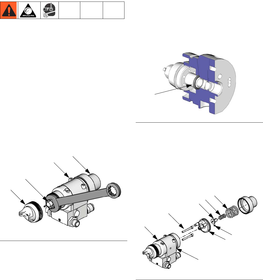
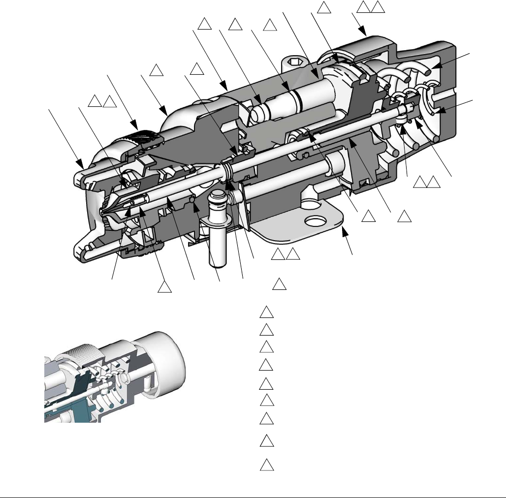
Disassembly
1. Perform Pressure Relief Procedure,
page 18.
2. Unscrew the four screws (13) and remove
the gun from the manifold.
3. Remove the air cap retainer (25) and air
cap (24).
4. Remove the piston cap (4) from the piston
housing (1). Remove the springs (6, 7).
5. Using a 1/16 in. hex wrench loosen the fluid
needle set screw (30). Remove the needle
stop (29).
6. Pull the fluid needle (5) out of the back of
the gun.
7. Check the fluid needle (5) for damage or
excessive wear. Replace the needle tip (5a)
or the entire needle if necessary.
8. Remove nozzle (23). Check nozzle and
o-ring (36) for damage.
9. Remove the piston. Using a pliers, pull the
piston (3) out of the piston housing (1).
10.Unscrew the two screws (14) and separate
the fluid housing (2) and the piston housing
(1). Remove gasket (12) only if it needs to
be replaced.
11.Remove the packing nut (16) with a
wrench.
12.Remove the fluid packing (17) from the nut
(16). Discard the old fluid packing.
FIG. 16
13 4
23
24, 25
ti13590a
FIG. 17
FIG. 18
36
ti8198a
14
2
1ti13591a
6
7
3
29
30
Service
24 313516G
13.Remove all o-rings from the piston (3) and
stems (T). Check that the stems are solidly
in place. If they are loose, replace the entire
piston assembly (3).
14.Perform the following applicable step:
a. Non-circulating guns: Remove the fluid
outlet port plug (19), and gasket (22)
from the fluid housing (2). Remove the
o-ring (21) and backup (20) from the
plug. See FIG. 21.
b. Circulating guns: Remove the gasket
(22) from the fluid housing (2). See FIG.
21.
15.Clean all parts and replace any worn parts.
When assembling, lubricate the threads
with anti-seize lubricant.
FIG. 19
SERVICE NOTES:
Torque to 35-45 in-lb (4.0-5.1 N•m).
Lubricate threads with anti-seize lubricant.
Lubricate with light-weight oil.
Tighten cap (4) until it bottoms out.
Apply semi-permanent anaerobic sealant.
Torque to 6.5-7.5 in-lb (0.73-0.85 N•m).
Torque to 95-105 in-lb (10.7-11.8 N•m).
Apply semi-permanent anaerobic sealant to two
threads at end of needle shaft.
Step in spacer (46) must face into packing nut.
1
4
3
2
8
7
6
9
Cutaway View:
Part No. 24A749 Gun Shown 4
6
7
29
30
1
8*
T
11*
10*
3
12*
9
16
5
5a
24 23
25 2
1
2
2
3
3
3
3
3
3
4
6 7
8
9
36
ti8199a
Alternate Fluid Control Shown
ti13592b
2
2
45 (x 2)
46 310
10
Service
313516G 25
Reassembly
1. Non-circulating guns only: Lubricate the
backup ring (20†) and o-ring (21†) and
install them on the fluid outlet port plug
(19). Install the plug in the fluid outlet port
of the fluid housing (2). See FIG. 21.
2. All guns: Reinstall the gasket (22) in the
fluid housing (2).
3. Install the o-rings (8*, 9*) on the piston (3).
Install the two o-rings (10*, 11*) on each of
the piston stems (T). Lubricate all the
o-rings, the piston, and the piston stems.
4. Remove the protective paper from the
sticky side of the gasket (12*) and adhere
the gasket to the bottom of the piston hous-
ing (1), making sure the three holes in the
gasket are properly aligned with the match-
ing holes in the housing.
5. Lubricate the washers (45†) and spacer
(46†). Insert them into the packing nut (16)
as shown in FIG. 20, The step on the
spacer faces into the packing nut.
6. Insert the packing nut into the fluid housing
(2) and torque to 95-105 in-lb (10.7-11.8
N•m).
7. Align the gasket (15*) as shown in the
exploded view in FIG. 21. Place the gasket
on the piston housing (1), then install the
fluid housing (2) onto the piston housing.
Torque the two screws (14) to 35-45 in-lb
(4.0-5.1 N•m).
a. Insert the piston (3) into the piston
housing (1).
b. Ensure nozzle sealing o-ring (36) is
installed on nozzle (23).
8. To avoid galling of the fluid nozzle seat in
the fluid housing, apply a thin film of lubri-
cant to the threads. Install the nozzle into
the fluid housing. Torque the nozzle
securely to 35-45 in-lb (4.0-5.1 N•m).
NOTE: If you are replacing the needle tip (5a),
apply semi-permanent anaerobic sealant to
two threads at the end of the needle shaft.
Assemble the needle tip to the shaft and hand
tighten. Allow adequate time for the sealant to
cure before installing the needle assembly into
the gun.
9. Lubricate and install the needle (5) into the
back of the gun assembly. Push it straight
in through the piston.
10.Install the needle stop (29) on the needle.
Coat the setscrew (30) with semi-perma-
nent anaerobic sealant and install the
screw into the needle stop. Torque to
6.5-7.5 in-lb (0.73-0.85 N•m). Pull on the
needle to make sure it seats fully.
11.Install the springs (6, 7).
12.Lubricate the threads of the piston housing
(1). Screw the cap (4) onto the housing
until it bottoms out.
13.Install the air cap (24) and air cap retainer
(25).
14.Reinstall the gun on the manifold using the
four screws (13). Start the threads of all
four screws. Tighten the front two screws
first, and then tighten the back two. Torque
all four screws evenly to 65 in-lb (7.3 N•m).
FIG. 20. Fluid packings
45
46
45
16
ti17603a
Parts
26 313516G
.Pa rts
Parts
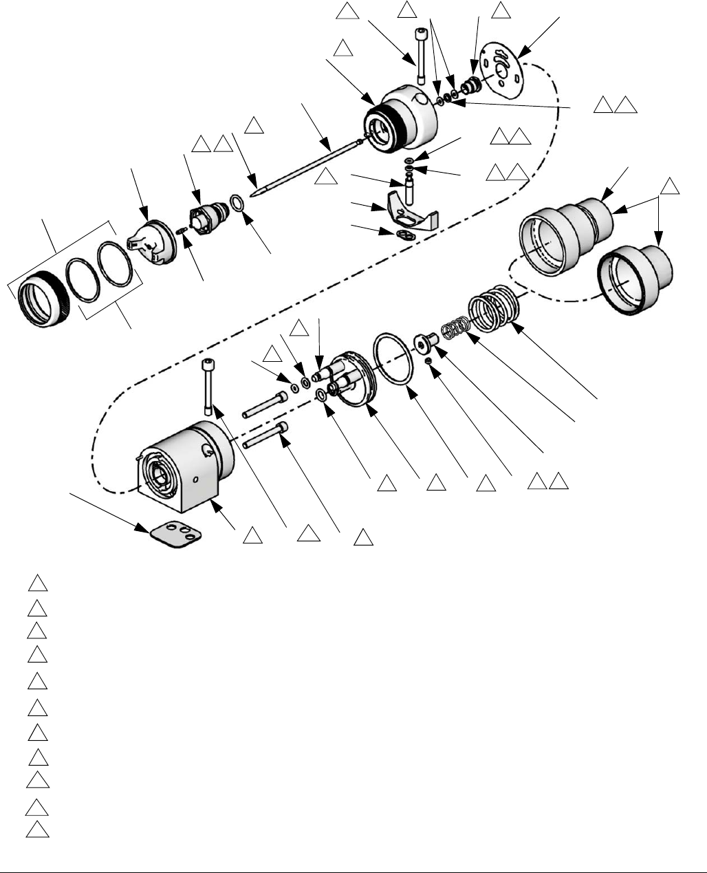
FIG. 21
SERVICE NOTES:
Torque to 35-45 in-lb (4.0-5.1 N•m).
Lubricate threads with anti-seize lubricant.
Lubricate with light-weight oil.
Tighten cap (4) until it bottoms out.
Apply semi-permanent anaerobic sealant.
Torque to 6.5-7.5 in-lb (0.73-0.85 N•m).
Torque to 95-105 in-lb (10.7-11.8 N•m).
Apply semi-permanent anaerobic sealant to two threads at end of needle shaft.
Used on non-circulating guns only.
Torque to 65 in-lb (7.3 N•m).
Step in spacer (46) must face into packing nut.
1
4
3
2
8
7
6
9
10
Part No. 24A749 Gun Shown
ti13593b
25
24 23
5
2
13 16 15*
19
21†
20† 4
7
6
30
29
8*3
11*
10*
1
12*
13
9*
T
1
38
2
3
3
6 7
3
3
3
3
3
214
25a
24a
39
10
10
10
2
36†
22†
5a 9Alternate Fluid
Control
4
1
11
11
11
45
46
12
3
12

Parts
313516G 27
* Included in Air Seal Repair Kit 288171.
† Included in Fluid Seal Repair Kit 24B675.
----- Not sold separately.
▲Replacement Warning labels, signs, tags, and
cards are available at no cost.
Ref. Part Description Qty.
1 ----- HOUSING, piston 1
2 24B676 HOUSING, fluid 1
3 240895 PISTON, assembly 1
4 See pages 28-29 CAP, piston 1
5 See pages 28-29 NEEDLE, assembly 1
5a See pages 28-29 TIP, needle 1
6 114139 SPRING, compres-
sion
1
7 114138 SPRING, compres-
sion
1
8* 115066 O-RING, fluoroelasto-
mer
1
9* 111450 O-RING, fluoroelasto-
mer
1
10* 111504 O-RING, fluoroelasto-
mer
2
11* 112319 O-RING, fluoroelasto-
mer
2
12* 114134 GASKET,
polyethylene (bottom)
1
13 15H317 SCREW, mounting
manifold (M5)
4
14 15H318 SCREW, SHC 2
15* 15H316 GASKET, polyethyl-
ene (front)
1
16 195222 NUT, packing 1
19 192687 PLUG, fluid 1
20† 114340 RING, back-up, PTFE 1
21† 114244 O-RING, fluoroelasto-
mer
1
22† 192443 GASKET, fluid 2
23 See pages 28-29 NOZZLE, fluid,
0.030 in.
1
24 See pages 28-29 CAP, air 1
24a 24B546 PIN, locating,
threaded; (pack of 10)
1
25 289079 RETAINER, ring,
assembly
1
25a 289791
-----
-----
SEAL KIT, air cap
(5 of each)
O-RING, PTFE
WASHER, UHMW
5
5
29 192452 STOP, needle 1
30 114137 SCREW, set 1
34 114141 WRENCH, hex, not
shown
1
36† 111457 O-RING 1
38 ----- PIN, dowel, not
shown
1
39 15H702 INSERT, plastic 1
40▲15K759 LABEL, warning, not
shown
1
45† ----- WASHER, UHMWPE 2
46† ----- SPACER, stainless
steel
1
Ref. Part Description Qty.

Repair Kits
28 313516G
Repair Kits
NOTE: Alternate nozzle sizes are also available. See Accessories, page 34.
General Metal Applications
Gun Part
Number Spray Type
Nozzle
Orifice
Size
in. (mm)
Needle/Nozzle
Kit
(Includes Items
5 and 23)
Item 4
Piston
Cap
Item 5
Needle
Assembly
(Includes
Needle Tip)
Item 5a
Needle
Tip
(Pack of 5)
Item 23
Nozzle
Item 24
Air Cap
(Includes
locating
pin)
Air Cap
(without
locating
pin)
24B333 Conventional 0.020 (0.5) 24B332 192453 24B331 289350 289061 24B544 289773
24A747 Conventional 0.030 (0.8) 24A687 192453 24A683 288183 289062 24B544 289773
24A748 Conventional 0.042 (1.1) 24A688 192453 24A684 288184 289063 24B544 289773
24A749 Conventional 0.055 (1.4) 24A689 192453 24A685 288185 289064 24B544 289773
24A750 Conventional 0.070 (1.8) 24A690 192453 24A685 288185 289065 24B545 289784
24B334 HVLP 0.020 (0.5) 24B332 192453 24B331 289350 289061 24B539 289041
24A754 HVLP 0.030 (0.8) 24A687 192453 24A683 288183 289062 24B539 289041
24A755 HVLP 0.042 (1.1) 24A688 192453 24A684 288184 289063 24B539 289041
24A756 HVLP 0.055 (1.4) 24A689 192453 24A685 288185 289064 24B539 289041
24A757 HVLP 0.070 (1.8) 24A690 192453 24A685 288185 289065 24B539 289041
24B335 Compliant 0.020 (0.5) 24B332 192453 24B331 289350 289061 24B540 289042
24A761 Compliant 0.030 (0.8) 24A687 192453 24A683 288183 289062 24B540 289042
24A762 Compliant 0.042 (1.1) 24A688 192453 24A684 288184 289063 24B540 289042
24A763 Compliant 0.055 (1.4) 24A689 192453 24A685 288185 289064 24B540 289042
24A764 Compliant 0.070 (1.8) 24A690 192453 24A685 288185 289065 24B540 289042
24A751★Conventional 0.030 (0.8) 24A687 24A512 24A683 288183 289062 24B544 289773
24A752★Conventional 0.042 (1.1) 24A688 24A512 24A684 288184 289063 24B544 289773
24A753★Conventional 0.055 (1.4) 24A689 24A512 24A685 288185 289064 24B544 289773
24A758★HVLP 0.030 (0.8) 24A687 24A512 24A683 288183 289062 24B539 289041
24A759★HVLP 0.042 (1.1) 24A688 24A512 24A684 288184 289063 24B539 289041
24A760★HVLP 0.055 (1.4) 24A689 24A512 24A685 288185 289064 24B539 289041
24A765★Compliant 0.030 (0.8) 24A687 24A512 24A683 288183 289062 24B540 289042
24A766★Compliant 0.042 (1.1) 24A688 24A512 24A684 288184 289063 24B540 289042
24A767★Compliant 0.055 (1.4) 24A689 24A512 24A685 288185 289064 24B540 289042

Repair Kits
313516G 29
High Wear Applications
Wood Applications
★Model has Fluid Control Knob (for fine adjustment of fluid flow).
✠ Needle tip and nozzle exit constructed from tungsten carbide.
Gun Part
Number Spray Type
Nozzle
Orifice
Size
in. (mm)
Needle/Nozzle
Kit
(Includes Items
5 and 23)
Item 4
Piston
Cap
Item 5
Needle
Assembly
(Includes
Needle Tip)
Item 5a
Needle
Tip
(Pack of 5)
Item 23
Nozzle
Item 24
Air Cap
(Includes
locating
pin)
Air Cap
(without
locating
pin)
24A774✠Conventional 0.059 (1.5) 24A693 192453 24A686 N/A 289074 24B537 288861
24A775✠Conventional 0.070 (1.8) 24A694 192453 24A686 N/A 289075 24B536 289049
24B336✠Conventional 0.086 (2.2) 24B358 192453 24B357 N/A 289076 24B536 289049
24C316✠Conventional 0.110 (2.8) 24C142 192453 24C319 N/A 289975 24B536 289049
24A776✠HVLP 0.059 (1.5) 24A695 192453 24A686 N/A 289331 24B541 289115
24A777✠HVLP 0.070 (1.8) 24A696 192453 24A686 N/A 289332 24B542 289325
24A778✠Compliant 0.059 (1.5) 24A695 192453 24A686 N/A 289331 24B538 289050
24A779✠Compliant 0.070 (1.8) 24A696 192453 24A686 N/A 289332 24B543 289327
Gun Part
Number Spray Type
Nozzle
Orifice
Size
in. (mm)
Needle/Nozzle
Kit
(Includes Items
5 and 23)
Item 4
Piston
Cap
Item 5
Needle
Assembly
(Includes
Needle Tip)
Item 5a
Needle
Tip
(Pack of 5)
Item 23
Nozzle
Item 24
Air Cap
(Includes
locating
pin)
Air Cap
(without
locating
pin)
24A768 Conventional 0.030 (0.8) 24A691 192453 24A683 288183 288927 24B533 288862
24A769 Conventional 0.040 (1.0) 24A692 192453 24A684 288184 289112 24B533 288862
24A770 HVLP 0.030 (0.8) 24A691 192453 24A683 288183 288927 24B535 288864
24A771 HVLP 0.040 (1.0) 24A692 192453 24A684 288184 289112 24B535 288864
24A772 Compliant 0.030 (0.8) 24A691 192453 24A683 288183 288927 24B534 288863
24A773 Compliant 0.040 (1.0) 24A692 192453 24A684 288184 289112 24B534 288863
Repair Kits
30 313516G
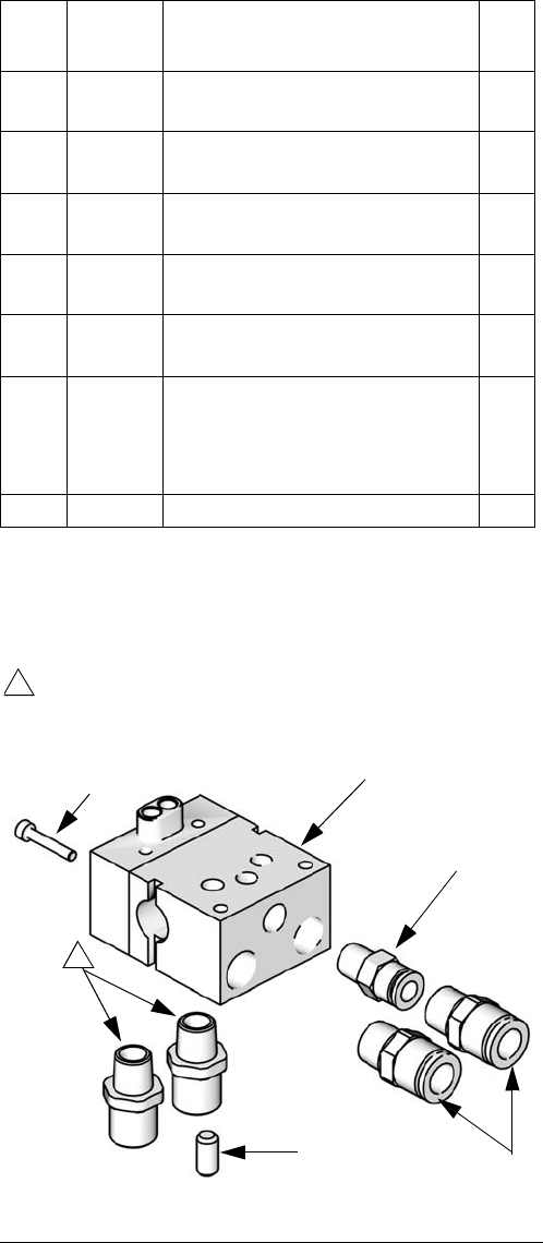
Part No. 288221
Manifold with bottom fluid ports
❄ Not shown.
----- Not sold separately.
Ref.
No. Part
No. Description Qty.
101 ----- MANIFOLD, bottom fluid
ports
1
103 120388 FITTING, tube, air inlet;
1/4 in. OD tube x 1/8 npt(m)
1
105 114246 SCREW, set; 5/16,
0.437 in. long
1
107 166846 NIPPLE, SST; 1/4 npsm,
straight pipe thread x 1/4 npt
2
108 120389 FITTING, tube, air line;
3/8 in.OD tube x 1/4 npt
2
109❄101970 PLUG, pipe, SST; 1/4-18 ptf,
supplied to plug fluid outlet
port in non-circulating appli-
cations
1
114 120453 SCREW, SHCS, M3 x 18 1
FIG. 22: Manifold with Bottom Fluid Ports
ti9398c
108
103
101
105
107
Apply anti-seize lubricant to threads and mating
faces of manifold (101) and any fittings and/or plugs
used in fluid ports.
1
1
114
Repair Kits
313516G 31
Part No. 288223
North America Low Pressure Manifold with
side fluid ports and fan adjustment valve
Part No. 24C342
International Low Pressure Manifold with side
fluid ports and fan adjustment valve
❄ Not shown, optional size
----- Not sold separately.
✠ Part No. 288223 only.
◆ Part No. 24C342 only.
Ref.
No. Part No. Description Qty.
101 ----- MANIFOLD, fan adjustable 1
102 243949 VALVE, fan, assy. 1
103
120388✠
120538◆
FITTING, tube, air inlet;
1/4 in. OD tube x 1/8 npt(m)
6 mm OD tube x 1/8 npt(m)
1
104
120389✠
120537◆
15D916◆❄
FITTING, tube, air line;
3/8 in.OD tube x 1/4 npt
8 mm OD tube x 1/4 npt
4 mm OD tube x 1/4 npt;
shipped loose
1
107 114246 SCREW, set; 5/16;0.437 in.
long
1
108
114342✠
114247◆
ELBOW, male
1/4 - 18 npt
#5JIC x 1/4-18 npt
2
109❄101970 PLUG, pipe, SST; 1/4-18
ptf, supplied to plug fluid
outlet port in non-circulat-
ing applications
1
114 120453 SCREW, SCHS, M3 x 18 1
FIG. 23: Side Fluid Ports and Fan Adjustment Valve
ti0556c
Apply anti-seize lubricant to threads and mating
faces of manifold (101) and any fittings and/or plugs
used in fluid ports.
1
Install with valve turned fully counterclockwise to
outermost position.
2
Torque to 125-135 in-lb (14-15 N•m).
3
104
103
107
108
108
102
1
2
3
101
114
Repair Kits
32 313516G
Part No. 288217
North America Manifold with side fluid ports
Part No. 288218
International Manifold with side fluid ports
❄ Not shown, optional size.
----- Not sold separately.
❖ Part No. 288217 only.
◆ Part No. 288218 only.
Ref.
No. Part No. Description Qty.
101 ----- MANIFOLD, side fluid
ports
1
103
120388❖
120538◆
FITTING, tube, air inlet
1/4 in. OD tube x 1/8
npt(m)
6 mm OD tube x 1/8
npt(m)
1
105 114246 SCREW, set; 5/16;
0.437 in. long
1
107
114342❖
114247◆
ELBOW, male, 1/4-18 npt
#5 JIC x 1/4-18 npt
2
108
120389❖
120537◆
15D916◆❄
FITTING, tube, air line
3/8 in.OD tube x 1/4
npt
8 mm OD tube x 1/4
npt
4 mm OD tube X 1/4
npt; shipped loose
2
109❄101970 PLUG, pipe, SST; 1/4-18
ptf, supplied to plug fluid
outlet port in non-circulat-
ing applications
1
114 120453 SCREW, SHCS, M3 x 18 1
FIG. 24: Manifold with Side Fluid Ports
ti8148c
Apply anti-seize lubricant to threads and mating
faces of manifold (101) and any fittings and/or plugs
used in fluid ports.
1
107
108
107
1
105
103
101
114
Repair Kits
313516G 33
Part No. 288160
Rear Port Manifold, North America
Part No. 288211
Rear Port Manifold, International
❄ Not shown, optional size.
----- Not sold separately
❖ Part No. 288160 only.
◆ Part No. 288211 only.
Ref.
No. Part No. Description Qty.
101 ----- MANIFOLD, aluminum 1
103
15H521❖
15J003◆
FITTING, fluid path
1/4 npsm
#5 JIC
2
105 116475 SCREW, SHCS, M4 x 12 2
106 120353 O-RING, PTFE 2
107 15J077 O-RING, PTFE 2
110 114246 SCREW, set, hex soc 1
111
120389❖
120537◆
15D916◆❄
FITTING, tube, air line
3/8 in. OD tube x 1/4 npt
8 mm OD tube x 1/4 npt
4 mm OD tube x 1/4
npt; shipped loose
2
112
120388❖
120538◆
FITTING, tube, air inlet
1/4 in. OD tube x
1/8 npt(m)
6 mm OD tube x
1/8 npt(m)
1
113 103253 SCREW, set 2FIG. 25: Manifold with Rear Fluid Ports
ti8200a
Apply sealant to threads and mating faces of
manifold (101) and any fittings and/or plugs used in
fluid ports.
1
Torque to 8-10 in-lb (0.9–1.3 N•m).
2
112
111
103
2
101
106
107
105
110 1
1
1
113
Torque to 110-130 in-lb (12.3–4.7 N•m).
3
2
3

Accessories
34 313516G
Accessories
Alternate Nozzle Sizes
Stainless Steel Air Cap Kits
Cleaning Brush 105749
For use in cleaning gun.
Lubricant 111265
One 4 oz. (113 gram) tube sanitary (non-sili-
cone) lubricant for fluid seals and wear areas.
Replacement Gun 24A780
Gun without needle, nozzle, and air cap.
Fluid Control Knob Repair Kit 288138
Includes spring, ball, and retaining clip.
Zero Cavity Needle Tip 24G618
1.1 mm needle tip, pack of 5.
Fluid Hose Parts Breakdown
Retrofit Adapter Plate 288197
The retrofit adapter plate enables the manifold
to be attached to a variety of bolt patterns. See
page 13 and page 42.
Gun Mounting Bracket (Cefla) Kit
24B609
Includes bracket and screw.
Gun Type Application
Nozzle
Orifice
in. (mm)
Air Cap
(without locating
pin) Nozzle
Needle
Tip
(Qty. 5)
Conventional
General Metal
0.086 (2.2) 289068 289066 289004
Conventional 0.110 (2.8) 289069 289067 289007
HVLP 0.086 (2.2) 289070 289066 289004
HVLP 0.110 (2.8) 289043 289067 289007
Compliant 0.086 (2.2) 289044 289066 289004
Compliant 0.110 (2.8) 289045 289067 289007
Conventional
Wood
0.020 (0.5) 288862 288907 289350
HVLP 0.020 (0.5) 288864 288907 289350
Compliant 0.020 (0.5) 288863 288907 289350
Gun Type Application Nozzle Orifice
in. (mm)
Air Cap
(without
locating pin)
Air Cap
(with Locating Pin)
Conventional
General Metal
0.020-0.055 (0.5-1.4) 24B671 24B667
Conventional 0.070 (1.8) 24B672 24B668
HVLP 0.020-0.070 (0.5-1.8) 24B669 24B665
Compliant 0.020-0.070 (0.5-1.8) 24B670 24B666
Part No. Description
239629 FITTING, assy, swivel
061345 TUBING, 1000 ft. (305 m) roll
Accessories
313516G 35
HVLP Pressure Verification Kit
For use in checking air cap atomizing and fan
pattern air pressure at various supply air pres-
sures. Not to be used for actual spraying.
Install the kit air cap on the gun. Turn on the air
to the gun, then trigger the gun and read the
air pressure on the gauge.
NOTE: To be “HVLP compliant,” the atomizing
and fan pattern air pressure must not exceed
10 psi (70 kPa, 0.7 bar).
Inline Fluid Filter 24B707
Filter is removable without disconnecting the
fluid line. Includes housing, o-ring, and
0.005 in. tip filter (equivalent to 100 mesh
screen).
Spray Tip Filters
Final filter to prevent foreign particles from
ruining sprayed surface smoothness.
Tips
Part No. Description
289563 HVLP General Metal
289568 HVLP High Wear 0.059 in. (1.5 mm)
289569 HVLP High Wear 0.070 in. (1.8 mm)
289566 HVLP Wood
FIG. 26: HVLP Pressure Verification Kit
ti13594a
25-Count
Carton 3-Pack Description
238562 238561 0.005 in. (equivalent to 100
mesh screen)
238564 238563 0.009 in. (equivalent to 60
mesh screen)
Part No. Description
24E484 0.030 in. SST Needle Tips (Pack of 5)
Dimensions
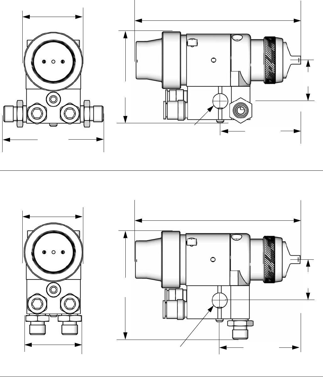
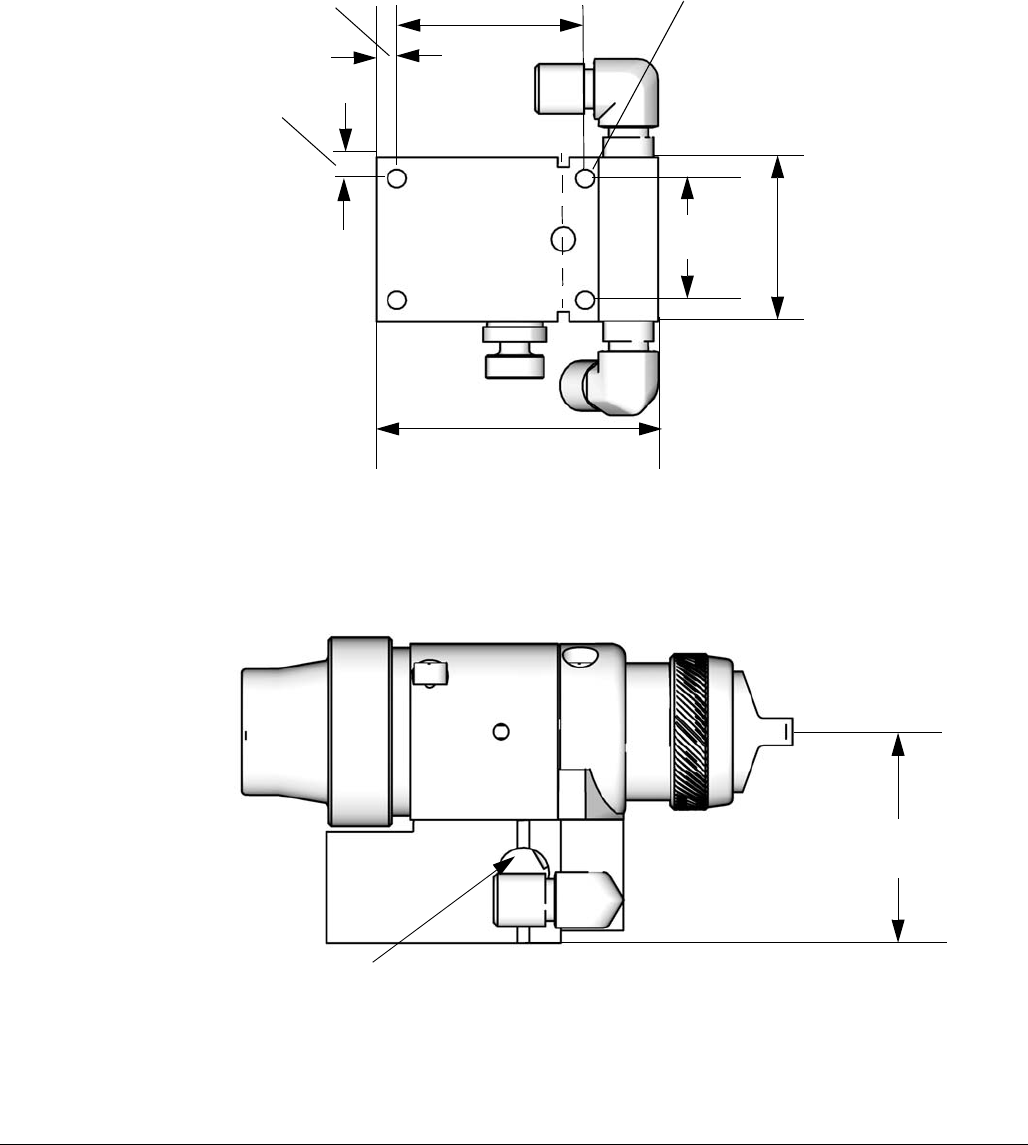
36 313516G
Dimensions
Manifold Models 288217 or 288218, All Gun Models
Manifold Model 288221, All Gun Models
FIG. 27
5.3 in. (134.6 mm)
6.4 in. (162.6 mm) with fluid control knob
ti13879ati13880a
3.9 in.
(99.1 mm)
3.0 in.
(76.2 mm)
1.4 in.
(35.6 mm)
2.8 in.
(71.1 mm)
0.5 in. (12.7 mm)
mounting hole
2.0 in.
(50.8 mm)
FIG. 28
5.3 in. (134.6 mm)
6.4 in. (162.6 mm) with fluid control knob
ti13881ati13882a
1.9 in.
(48.3 mm)
3.7 in.
(94.0 mm)
1.4 in.
(35.6 mm)
2.7 in.
(68.6 mm)
0.5 in. (12.7 mm)
mounting hole
2.0 in.
(50.8 mm)
Dimensions
313516G 37
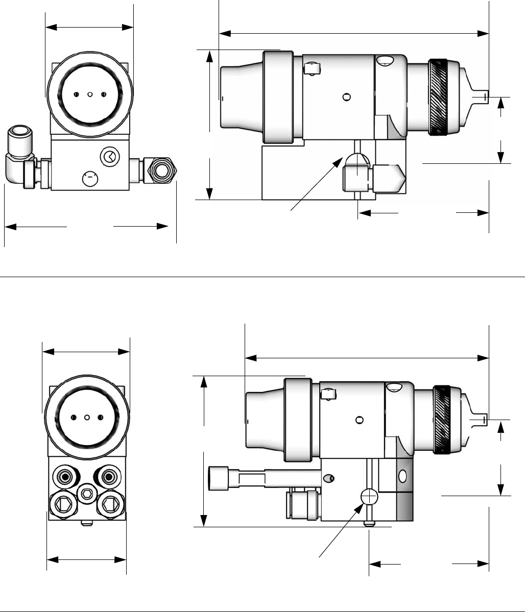
Manifold Model 288223 or 24C342, All Gun Models
Manifold Model 288160 or 288211, All Gun Models
FIG. 29
5.3 in. (134.6 mm)
6.4 in. (162.6 mm) with fluid control knob
ti13883ati13884a
3.8 in.
(96.5 mm)
3.0 in.
(76.2 mm)
1.4 in.
(35.6 mm)
2.7 in.
(68.6 mm)
0.5 in. (12.7 mm)
mounting hole
2.0 in.
(50.8 mm)
FIG. 30
5.3 in. (134.6 mm)
6.4 in. (162.6 mm) with fluid control knob
ti13881ati13886a
1.8 in.
(45.7 mm)
3.4 in.
(86.4 mm) 1.8 in.
(45.7 mm)
2.7 in.
(68.6 mm)
0.375 in. (95 mm)
mounting hole
2.0 in.
(50.8 mm)
Mounting Hole Layouts
38 313516G
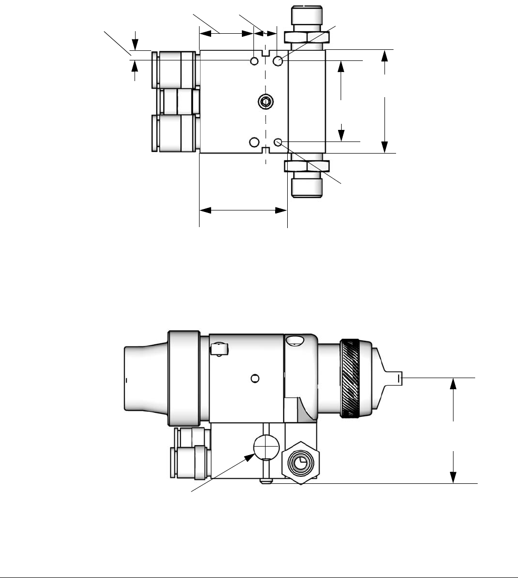
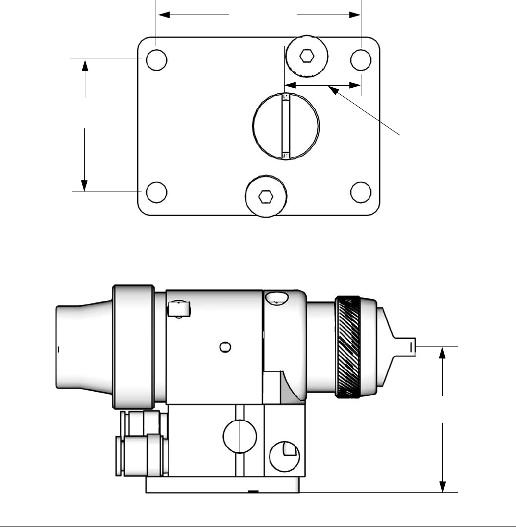
Mounting Hole Layouts
Manifold Models 288217 or 288218, All Gun Models
FIG. 31
ti13887a
1.75 in.
(44.4 mm)
1.375 in.
(34.9 mm)
1.5 in.
(38.1 mm)
0.16 in.
(4.1 mm)
0.92 in.
(23.4 mm)
0.4 in.
(10.2 mm) Two M5 x 0.8 x 0.25 in.
(6.3 mm) holes
Two 0.13 diameter x
0.31 in. (7.8 mm)
holes. Use 1/8 in. pin
for alignment
0.5 in. (12.7 mm)
mounting hole
2.1 in.
(53.3 mm)
ti13879a
Mounting Hole Layouts
313516G 39
Manifold Model 288221, All Gun Models
FIG. 32
ti13888a
1.75 in.
(44.4 mm)
1.375 in.
(34.9 mm)
2.1 in.
(53.3 mm)
0.18 in.
(4.6 mm)
0.92 in.
(23.4 mm)
0.4 in.
(10.2 mm) Two M5 x 0.8 x 0.25 in.
(6.3 mm) holes
Two 0.13 diameter x
0.31 in. (7.8 mm)
holes. Use 1/8 in. pin
for alignment
0.50 in. (12.7 mm)
mounting hole
2.8 in.
(71.1 mm)
ti13881a
Mounting Hole Layouts
40 313516G
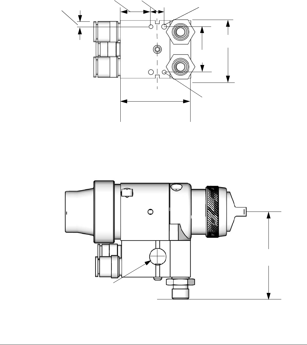
Manifold Model 288223 or 24C342, All Gun Models
FIG. 33
ti13889a
1.75 in.
(44.4 mm)
1.3 in.
(33 mm)
3.0 in.
(76.2 mm)
0.225 in.
(5.7 mm)
2.0 in.
(50.8 mm)
0.216 in.
(5.5 mm)
Four M6 x 1.0 x 0.34 in.
(6.3 mm) holes
0.5 in. (12.7mm)
mounting hole
2.1 in.
(53.3 mm)
ti13879a
Mounting Hole Layouts
313516G 41
Manifold Model 288160 or 288211, All Gun Models
FIG. 34
ti13890a
1.75 in.
(44.4 mm
1.375 in.
(34.9 mm
1.1 in.
(27.9 mm)
0.19 in.
(4.8mm)
0.92 in.
(23.4 mm) 0.4 in.
(10.2 mm)
Two M5 x 0.8 x 0.25 in.
(6.3 mm) holes
Two 0.13 diameter x
0.31 in. (7.8 mm)
holes. Use 1/8 in. pin
for alignment
0.375 in. (9.5 mm)
mounting hole
2.3 in.
(58.4 mm)
ti13885a
Mounting Hole Layouts
42 313516G
FIG. 35
Retrofit Adapter Plate 288197
For use with manifold models 288217, 288218, 288221, 288216, and 288211
ti8178a
2.0 in.
(51 mm)
1.4 in.
(34.9 mm) 0.74 in.
(18.7 mm)
ti13600a
2.3 in.
(57.7 mm)

Technical Data
313516G 43
Technical Data
Triggering Speed
These values apply to a new gun with a 12 ft. (3.6 m), 1/4 in. (6.3 mm) OD cylinder air line and a
0.055 in. nozzle. These values will vary slightly with use and with variations in equipment.
Sound Data
Sound power measured per ISO 9614-2.
Maximum Working Fluid Pressure . . . . . . . . . . . . . . . . . . . 100 psi (0.7 MPa, 7 bar)
Maximum Working Air Pressure. . . . . . . . . . . . . . . . . . . . . 100 psi (0.7 MPa, 7 bar)
Maximum HVLP and Compliant Gun
Inbound Air Pressure . . . . . . . . . . . . . . . . . . . . . . . . . . See chart on page 7.
Maximum Working Fluid Temperature . . . . . . . . . . . . . . . . 120° F (49° C)
Minimum Air Cylinder Actuation Pressure . . . . . . . . . . . . . 50 psi (0.34 MPa, 3.4 bar)
Weight . . . . . . . . . . . . . . . . . . . . . . . . . . . . . . . . . . . . . . . . 1.5 lbs (680 g)
Wetted Parts
Models 24B333-24B335 and 24A747-24A773 . . . . . . .
Models 24A774-24A779 . . . . . . . . . . . . . . . . . . . . . . . .
Stainless Steel, Ultra High Molecular
Weight Polyethylene, Acetal, PTFE,
PEEK
Stainless Steel, Ultra High Molecular
Weight Polyethylene, Acetal, PTFE,
Tungsten Carbide
Cylinder Air
Pressure
psi (kPa, bar)
Fluid Pressure
psi (kPa, bar)
Air Pressure
psi (kPa, bar)
msec to fully
open msec to fully
close
50 (0.35, 3.5) 50 (0.35, 3.5) 100 (0.7, 7.0) 58.4 50.4
Conventional
Measured at 44 psi (0.30 MPa, 3.0 bar) atomizing air and
47 psi (0.32 MPa, 3.2 bar) fan air pressure
Sound Power. . . . . . . . . . . . . . . . . . . . . . . . . . . . . . . .
Sound Pressure . . . . . . . . . . . . . . . . . . . . . . . . . . . . .
88.82 dBa
78.91 dBa
HVLP
Measured at 17 psi (0.12 MPa, 1.2 bar) atomizing air
and 29 psi (0.20 MPa, 2.0 bar) fan air pressure
Sound Power. . . . . . . . . . . . . . . . . . . . . . . . . . . . . . . .
Sound Pressure . . . . . . . . . . . . . . . . . . . . . . . . . . . . .
89.70 dBa
79.79 dBa
Compliant
Measured at 29 psi (0.20 MPa, 2.0 bar) atomizing air and
33 psi (0.23 MPa, 2.3 bar) fan air pressure
Sound Power. . . . . . . . . . . . . . . . . . . . . . . . . . . . . . . .
Sound Pressure . . . . . . . . . . . . . . . . . . . . . . . . . . . . .
87.47 dBa
77.56 dBa
All written and visual data contained in this document reflects the latest product information available at the time of publication.
Graco reserves the right to make changes at any time without notice.
Original instructions. This manual contains English. MM 313516
Graco Headquarters: Minneapolis
International Offices: Belgium, China, Japan, Korea
GRACO INC. AND SUBSIDIARIES • P.O. BOX 1441 • MINNEAPOLIS MN 55440-1441 • USA
Copyright 2009, Graco Inc. All Graco manufacturing locations are registered to ISO 9001.
www.graco.com
Revised 01/2012
Graco Standard Warranty
Graco warrants all equipment referenced in this document which is manufactured by Graco and bearing its name to be free from defects in
material and workmanship on the date of sale to the original purchaser for use. With the exception of any special, extended, or limited warranty
published by Graco, Graco will, for a period of twelve months from the date of sale, repair or replace any part of the equipment determined by
Graco to be defective. This warranty applies only when the equipment is installed, operated and maintained in accordance with Graco’s written
recommendations.
This warranty does not cover, and Graco shall not be liable for general wear and tear, or any malfunction, damage or wear caused by faulty
installation, misapplication, abrasion, corrosion, inadequate or improper maintenance, negligence, accident, tampering, or substitution of
non-Graco component parts. Nor shall Graco be liable for malfunction, damage or wear caused by the incompatibility of Graco equipment with
structures, accessories, equipment or materials not supplied by Graco, or the improper design, manufacture, installation, operation or
maintenance of structures, accessories, equipment or materials not supplied by Graco.
This warranty is conditioned upon the prepaid return of the equipment claimed to be defective to an authorized Graco distributor for verification of
the claimed defect. If the claimed defect is verified, Graco will repair or replace free of charge any defective parts. The equipment will be returned
to the original purchaser transportation prepaid. If inspection of the equipment does not disclose any defect in material or workmanship, repairs will
be made at a reasonable charge, which charges may include the costs of parts, labor, and transportation.
THIS WARRANTY IS EXCLUSIVE, AND IS IN LIEU OF ANY OTHER WARRANTIES, EXPRESS OR IMPLIED, INCLUDING BUT NOT LIMITED
TO WARRANTY OF MERCHANTABILITY OR WARRANTY OF FITNESS FOR A PARTICULAR PURPOSE.
Graco’s sole obligation and buyer’s sole remedy for any breach of warranty shall be as set forth above. The buyer agrees that no other remedy
(including, but not limited to, incidental or consequential damages for lost profits, lost sales, injury to person or property, or any other incidental or
consequential loss) shall be available. Any action for breach of warranty must be brought within two (2) years of the date of sale.
GRACO MAKES NO WARRANTY, AND DISCLAIMS ALL IMPLIED WARRANTIES OF MERCHANTABILITY AND FITNESS FOR A
PARTICULAR PURPOSE, IN CONNECTION WITH ACCESSORIES, EQUIPMENT, MATERIALS OR COMPONENTS SOLD BUT NOT
MANUFACTURED BY GRACO. These items sold, but not manufactured by Graco (such as electric motors, switches, hose, etc.), are subject to
the warranty, if any, of their manufacturer. Graco will provide purchaser with reasonable assistance in making any claim for breach of these
warranties.
In no event will Graco be liable for indirect, incidental, special or consequential damages resulting from Graco supplying equipment hereunder, or
the furnishing, performance, or use of any products or other goods sold hereto, whether due to a breach of contract, breach of warranty, the
negligence of Graco, or otherwise.
FOR GRACO CANADA CUSTOMERS
The Parties acknowledge that they have required that the present document, as well as all documents, notices and legal proceedings entered into,
given or instituted pursuant hereto or relating directly or indirectly hereto, be drawn up in English. Les parties reconnaissent avoir convenu que la
rédaction du présente document sera en Anglais, ainsi que tous documents, avis et procédures judiciaires exécutés, donnés ou intentés, à la suite
de ou en rapport, directement ou indirectement, avec les procédures concernées.
Graco Information
For the latest information about Graco products, visit www.graco.com.
TO PLACE AN ORDER, contact your Graco distributor or call to identify the nearest distributor.
Phone: 612-623-6921 or Toll Free: 1-800-328-0211 Fax: 612-378-3505
