Graco 313997W Hfr Users Manual HFR, Setup Operation, English
2015-04-02
: Graco Graco-313997W-Hfr-Users-Manual-685868 graco-313997w-hfr-users-manual-685868 graco pdf
Open the PDF directly: View PDF ![]() .
.
Page Count: 112 [warning: Documents this large are best viewed by clicking the View PDF Link!]
- Related Manuals
- Models
- Product Configurator
- Whip Hose Bundles
- Individual B (Blue) Heated Whip Hose
- Individual A (Red) Heated Whip Hose
- B (Blue) Individual
- A (Red) Individual
- Hose Bundling Accessories
- Applicator
- B (Blue) Applicator Orifice
- Iso A (Red) Applicator Orifice
- AC Power Pack with S-Head/L-Head Hoses, Optional Boom
- Dispense Valve Interface Kit
- Flow Meters
- Pump Feed Kits
- B (Blue) and A (Red) Feed Tanks
- Warnings
- Important Two-Component Material Information
- A (Red) and B (Blue) Components
- Typical Installation
- Component Identification
- Dispense Valves Overview
- Setup
- Advanced Display Module (ADM) Operation
- Startup
- Shutdown
- Pressure Relief Procedure
- Flushing
- Maintenance
- Troubleshooting
- Appendix A - ADM Icons Overview
- Appendix B - ADM Setup Screens Overview
- Appendix C - ADM Run Screens Overview
- Appendix D - ADM Error Codes
- Appendix E - System Events
- Appendix F - USB Operation
- Technical Data
- Motor Control Module Technical Data
- Graco Standard Warranty
- Graco Information
313997W
EN
Setup - Operation
HFR™
Hydraulic, Plural-Component, Fixed-Ratio Proportioner.
For pouring and dispensing sealants and adhesives and polyurethane foam.
For professional use only. Not for use in explosive atmospheres.
See page 4 for model information and maximum
working pressure.
Important Safety Instructions
Read all warnings and instructions in this
manual. Save these instructions.
ti19598a
2313997W
Contents
Related Manuals . . . . . . . . . . . . . . . . . . . . . . . . . . . 3
Models . . . . . . . . . . . . . . . . . . . . . . . . . . . . . . . . . . . 4
Product Configurator . . . . . . . . . . . . . . . . . . . . . . . 5
Whip Hose Bundles . . . . . . . . . . . . . . . . . . . . . . 7
Individual B (Blue) Heated Whip Hose . . . . . . . . 7
Individual A (Red) Heated Whip Hose . . . . . . . . 7
B (Blue) Individual . . . . . . . . . . . . . . . . . . . . . . . . 8
A (Red) Individual . . . . . . . . . . . . . . . . . . . . . . . . 9
Hose Bundling Accessories . . . . . . . . . . . . . . . . 9
Applicator . . . . . . . . . . . . . . . . . . . . . . . . . . . . . 10
B (Blue) Applicator Orifice . . . . . . . . . . . . . . . . . 11
Iso A (Red) Applicator Orifice . . . . . . . . . . . . . . 13
AC Power Pack with S-Head/L-Head Hoses,
Optional Boom . . . . . . . . . . . . . . . . . . . . . . 14
Dispense Valve Interface Kit . . . . . . . . . . . . . . 14
Flow Meters . . . . . . . . . . . . . . . . . . . . . . . . . . . . 14
Pump Feed Kits . . . . . . . . . . . . . . . . . . . . . . . . . 15
B (Blue) and A (Red) Feed Tanks . . . . . . . . . . 16
Warnings . . . . . . . . . . . . . . . . . . . . . . . . . . . . . . . . 18
Important Two-Component Material Information 20
Isocyanate Conditions . . . . . . . . . . . . . . . . . . . . 20
Material Self-ignition . . . . . . . . . . . . . . . . . . . . . 20
Keep Components A (Red) and B (Blue) Separate
20
Moisture Sensitivity of Isocyanates . . . . . . . . . . 21
Foam Resins with 245 fa Blowing Agents . . . . . 21
Changing Materials . . . . . . . . . . . . . . . . . . . . . . 21
A (Red) and B (Blue) Components . . . . . . . . . . . . 21
Typical Installation . . . . . . . . . . . . . . . . . . . . . . . . 23
Component Identification . . . . . . . . . . . . . . . . . . . 24
Hydraulic Power Pack . . . . . . . . . . . . . . . . . . . . 27
Motor Control Module (MCM) . . . . . . . . . . . . . . 28
Advanced Display Module (ADM) . . . . . . . . . . . 30
Fluid Control Module (FCM) . . . . . . . . . . . . . . . 33
Temperature Control Module (Heated HFR Only) 34
Dispense Valves Overview . . . . . . . . . . . . . . . . . . 37
Setup . . . . . . . . . . . . . . . . . . . . . . . . . . . . . . . . . . . . 38
Vacuum De-gas . . . . . . . . . . . . . . . . . . . . . . . . . 44
Vacuum De-gas and Vacuum Manual Refill . . . 45
Advanced Display Module (ADM) Operation . . . . 46
Startup . . . . . . . . . . . . . . . . . . . . . . . . . . . . . . . . . . 47
Shutdown . . . . . . . . . . . . . . . . . . . . . . . . . . . . . . . . 50
Pressure Relief Procedure . . . . . . . . . . . . . . . . . . 51
Flushing . . . . . . . . . . . . . . . . . . . . . . . . . . . . . . . . . 52
Maintenance . . . . . . . . . . . . . . . . . . . . . . . . . . . . . . 53
ADM - Battery Replacement and Screen Cleaning
54
MCM and TCM - Clean Heat Sink Fins . . . . . . . 54
Install Upgrade Tokens . . . . . . . . . . . . . . . . . . . 55
Fluid Inlet Strainer Screen . . . . . . . . . . . . . . . . . 56
IsoGuard Select® System . . . . . . . . . . . . . . . . . 57
Troubleshooting . . . . . . . . . . . . . . . . . . . . . . . . . . . 58
Light Tower (Optional) . . . . . . . . . . . . . . . . . . . . 58
Common Problems . . . . . . . . . . . . . . . . . . . . . . 58
ADM Troubleshooting . . . . . . . . . . . . . . . . . . . . 61
Motor Control Module . . . . . . . . . . . . . . . . . . . . 62
Fluid Control Module . . . . . . . . . . . . . . . . . . . . . 64
Temperature Control Module . . . . . . . . . . . . . . . 65
Appendix A - ADM Icons Overview . . . . . . . . . . . 66
Setup Screen Icons . . . . . . . . . . . . . . . . . . . . . . 66
Run Screen Icons . . . . . . . . . . . . . . . . . . . . . . . 67
Appendix B - ADM Setup Screens Overview . . . . 68
Appendix C - ADM Run Screens Overview . . . . . 82
Appendix D - ADM Error Codes . . . . . . . . . . . . . . 88
Appendix E - System Events . . . . . . . . . . . . . . . 100
Appendix F - USB Operation . . . . . . . . . . . . . . . . 102
Overview . . . . . . . . . . . . . . . . . . . . . . . . . . . . . 102
USB Options . . . . . . . . . . . . . . . . . . . . . . . . . . 102
Download Log Files . . . . . . . . . . . . . . . . . . . . . 102
Log Files, Folder Structure . . . . . . . . . . . . . . . 103
Transfer System Settings . . . . . . . . . . . . . . . . . 105
Update Custom Language . . . . . . . . . . . . . . . . 106
Technical Data . . . . . . . . . . . . . . . . . . . . . . . . . . . 108
Motor Control Module Technical Data . . . . . . . . 109
Dimensions . . . . . . . . . . . . . . . . . . . . . . . . . . . 110
Graco Standard Warranty . . . . . . . . . . . . . . . . . . 112
Graco Information . . . . . . . . . . . . . . . . . . . . . . . . 112

Related Manuals
313997W 3
Related Manuals
Manuals are available at www.graco.com.
Component manuals in English:
System Manuals
313998 HFR Repair-Parts
Power Distribution Box Manual
3A0239 Power Distribution Boxes Instruc-
tions-Parts
Pumpline Manuals
3A0019 Z-Series Chemical Pumps Instruc-
tions-Parts
3A0020 HFR Hydraulic Actuator Instruc-
tions-Parts
Feed System Manuals
3A0238 Dispense Head Hydraulic Power
Pack Instructions-Parts
3A0235 Feed Supply Kits
Instructions-Parts
3A0395 Stainless Steel Tank Feed Sys-
tems Instructions-Parts
3A1299 Carbon Steel Tank Feed Systems
Instructions-Parts
3A0237 Heated Hoses and Applicator Kits,
Instructions-Parts
Dispense Valve Manuals
313872 EP™ Gun
313536 GX-16, Operation
312185 MD2 Valve, Instructions-Parts
312752 S-Head Operation-Parts
312753 L-Head Operation-Parts
309550 Fusion® AP Gun
309856 Fusion MP Gun
312666 Fusion CS Gun
Accessory Manuals
3A1149 HFR Discrete Gateway Module
Kits Manual
312864 HFR Communications Gateway
Module Instructions-Parts
3A1657 HFR Flow Meter Kits
Instructions-Parts
3A1244 Graco Control Architecture™ Mod-
ule Programming Manual
3A2890 Mobile Pallet with Casters Kit Man-
ual
Models
4313997W
Models
See Product Configurator on page 5 for detailed product configuration information.
* Full load amps with all devices operating at maximum capabilities. Fuse requirements at various flow rates and
mix chamber sizes may be less.
†210 ft (64 m) maximum heated hose length, including whip hose.
★ approved.
‡The maximum fluid working pressure for the base machine without hoses is 3000 psi (20.7 MPa, 207 bar). If
hoses rated at less than 3000 psi are installed, the system maximum fluid working pressure becomes the rating of
the hoses. If 2000 psi hoses were purchased and installed by Graco, the working pressure for the machine is
already setup for the lower 2000 psi (13.8 MPa, 138 bar) working pressure by Graco. If the machine was pur-
chased without hoses and aftermarket hoses rated at or above 3000 psi are to be installed, see instruction man-
ual 313998 for the procedure to setup the machine for higher rated hoses. The change in working pressure is
made by changing a rotary switch setting in the Motor Control Module. The minimum pressure rating for hoses is
2000 psi. Do not install hoses with a pressure rating lower than 2000 psi.
✖See 400 V Power Requirements.
400 V Power Requirements
• 400 V systems are intended for International voltage
requirements. Not for voltage requirements in North
America.
• If a 400 volt configuration is operated in North Amer-
ica, a special transformer rated for 400 V (“Y” con-
figuration (4 wire)) may be required.
• North America mostly employs a 3 wire or Delta
configuration. The two configurations are not inter-
changeable.
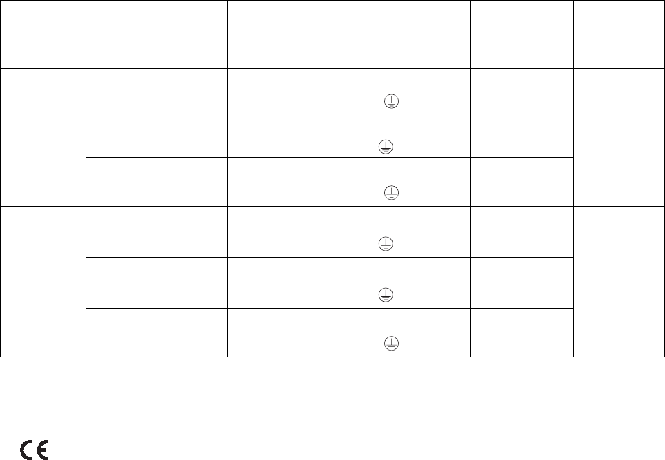
System
Full Load
Peak Amps
Per Phase*
Voltage
(phase) Power Description System Watts †
Maximum
Fluid Working
Pressure ‡
psi (MPa, bar)
HFR,
Non-Heated
55 A 230V (1) 200-240VAC, 1 phase, 50/60Hz,
2 wire and PE 12, 650
3000
(20.7, 207)
29 A 230V (3) 200-240VAC, 3 phase Δ, 50/60Hz, 3
wire and PE
11,340
55 A ★✖ 400V (3) 380-415VAC, 3 phase Y, 50/60Hz,
2 wire and PE 12,650
HFR,
Heated
116 A 230V (1) 200-240VAC, 3 phase Δ, 50/60Hz, 3
wire and PE
26,680
3000
(20.7, 207)
73 A 230V (3) 200-240VAC, 3 phase Δ, 50/60Hz, 3
wire and PE
28,600
75 A ★✖ 400V (3) 380-415VAC, 3 phase Y, 50/60Hz,
2 wire and PE 28,600
Product Configurator
313997W 5
Product Configurator
An example of the product configurator would be the following configurator code.
The following part number fields apply for the HFR part numbering configurator fields.
HFR-A------
Ref.: 12345 6
Configurator Revision
Base
Voltage
B (Blue) Pump
A (Red) Pump
Primary/Hose Heat
High Volume/Low Volume
Hose Bundle Assembly
HFR - A - 1 - 6 - AM - AM - D - AG
Ref.: 123456
Configurator Revision
Base
Voltage
B (Blue) Pump
A (Red) Pump
Primary/Hose Heat
High Volume/Low Volume
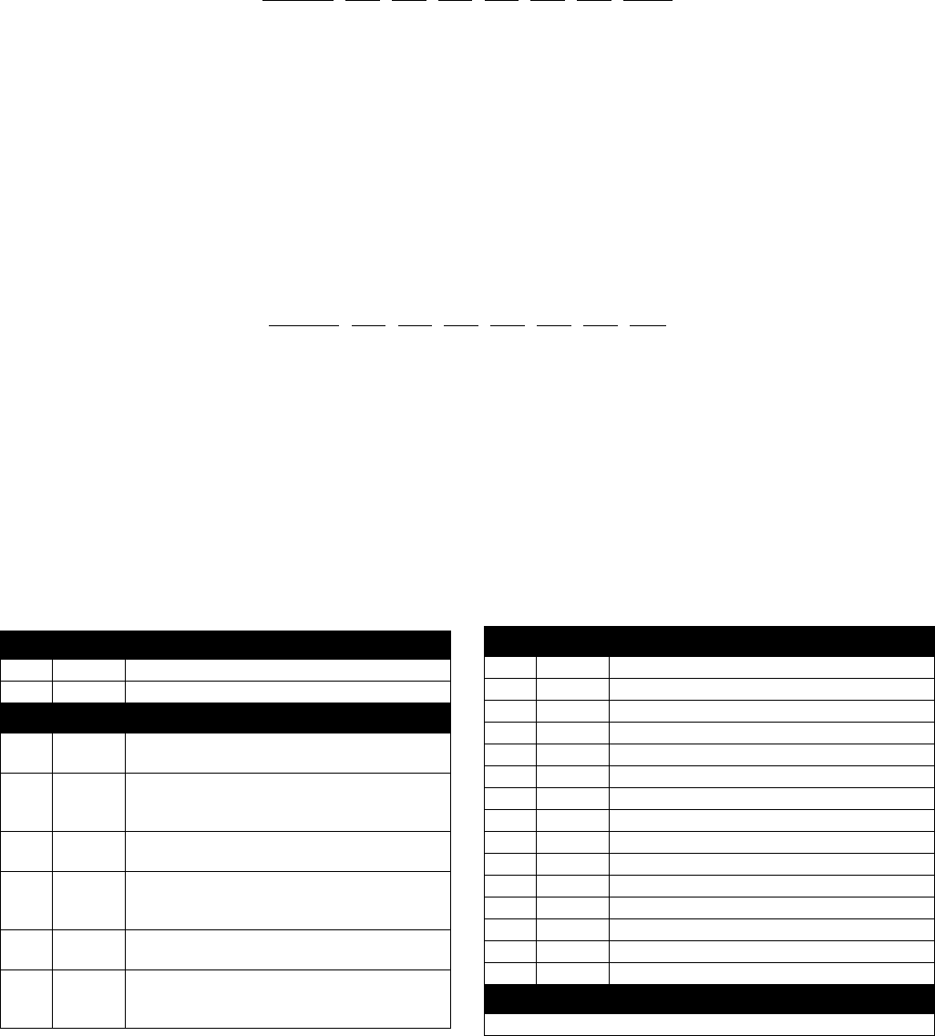
Ref. 1 Part Base Unit
1 HFR Base Unit, Carbon Steel
2 HFR Base Unit, Stainless Steel
Ref. 2 Part Voltage
1 230V, 1 phase;
No Heat
2 230V, 1 phase;
Maximum of Two 6 kW Primary Heater and One
Zone of Hose Heat
3 230V, 3 phase;
No Heat
4 230V, 3 phase;
Maximum of Two 6 kW Primary Heaters and Two
Zones of Hose Heat
5 400V, 3 phase;
No heat
6 400V, 3 phase;
Maximum of Two 6 kW Primary Heaters and Two
Zones of Hose Heat
Ref. 3 Part B (Blue) Pump †
AA L010S1 10 cc Stainless Steel
AB L015S1 15 cc Stainless Steel
AC L020S1 20 cc Stainless Steel
AD L025S1 25 cc Stainless Steel
AE L030S1 30 cc Stainless Steel
AF L040S1 40 cc Stainless Steel
AG L050S1 50 cc Stainless Steel
AH L060S1 60 cc Stainless Steel
AJ L080S1 80 cc Stainless Steel
AK L100S1 100 cc Stainless Steel
AL L120S1 120 cc Stainless Steel
AM L160S1 160 cc Stainless Steel
AN L005S1 5 cc Stainless Steel
AP L086S1 86 cc Stainless Steel
AQ L065S1 65 cc Stainless Steel
Ref. 4 Part A (Red) Pump †
Code, Part, and Description for Ref. 4 are the same as Ref. 3

Product Configurator
6313997W
† Pump size listed is the combined volume dispensed
in one extending stroke and one retracting stroke.
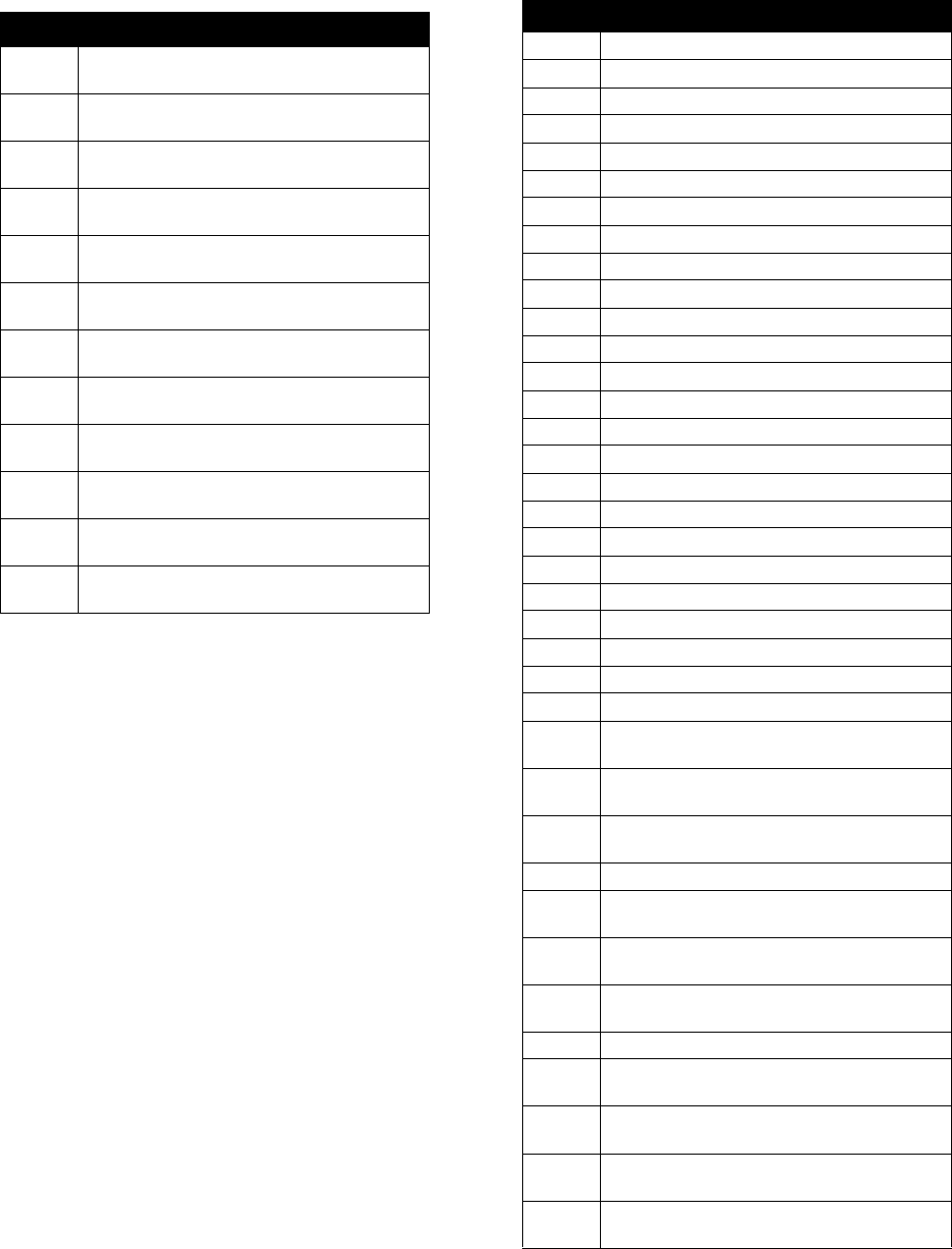
Ref. 5 Part Primary/Hose Heat
A No Heat
B A (Red) and B (Blue) Primary Heaters
C A (Red) and B (Blue) Primary Heaters, One Zone
of Hose Heat
D A (Red) and B (Blue) Primary Heaters, A (Red)
and B (Blue) Hose Heat
E A (Red) and B (Blue) Hose Heat, Carbon Steel
F A (Red) and B (Blue) Hose Heat, Stainless Steel
G B (Blue) Primary Heaters, B (Blue) Hose Heat
Ref. 6 Part
B (Blue) Applicator Hose or High Volume/
Low Volume Hose Bundle Assembly
NN -- No Hose
AA 24D108 Dual Hose, 2:1, 1/4 x 3/8, 5 ft, Stainless Steel,
3500 psi
AB 24D109 Dual Hose, 2:1, 1/4 x 3/8, 10 ft, Stainless Steel,
3500 psi
AC 24D110 Dual Hose, 2:1, 1/4 x 3/8, 25 ft, Stainless Steel,
3500 psi
AD 24D111 Dual Hose, 2:1, 1/4 x 3/8, 50 ft, Stainless Steel,
3500 psi
AE 24D112 Dual Hose, 1:1, 3/8 x 3/8, 5 ft, Stainless Steel,
3500 psi
AF 24D113 Dual Hose, 1:1, 3/8 x 3/8, 10 ft, Stainless Steel,
3500 psi
AG 24D114 Dual Hose, 1:1, 3/8 x 3/8, 25 ft, Stainless Steel,
3500 psi
AH 24D115 Dual Hose, 1:1, 3/8 x 3/8, 50 ft, Stainless Steel,
3500 psi
BA 24D116 Dual Hose, 2:1, 1/4 x 3/8, 5 ft, Stainless Steel,
3500 psi
BB 24D117 Dual Hose, 2:1, 1/4 x 3/8, 10 ft, Carbon Steel,
3500 psi
BC 24D118 Dual Hose, 2:1, 1/4 x 3/8, 25 ft, Carbon Steel,
3500 psi
BD 24D119 Dual Hose, 2:1, 1/4 x 3/8, 50 ft, Carbon Steel,
3500 psi
BE 24D120 Dual Hose, 1:1, 3/8 x 3/8, 5 ft, Carbon Steel,
3500 psi
BF 24D121 Dual Hose, 1:1, 3/8 x 3/8, 10 ft, Carbon Steel,
3500 psi
BG 24D122 Dual Hose, 1:1, 3/8 x 3/8, 25 ft, Carbon Steel,
3500 psi
BH 24D123 Dual Hose, 1:1, 3/8 x 3/8, 50 ft, Carbon Steel,
3500 psi
CA 24E968 Single Hose, 1:1, 1/4 x 1/4, 10 ft, Carbon Steel,
2000 psi
CB 24E963 Single Hose, 1:1, 1/4 x 1/4, 25 ft, Carbon Steel,
2000 psi
CC 24E964 Single Hose, 1:1, 1/4 x 1/4, 50 ft, Carbon Steel,
2000 psi
CD 24D124 Single Hose, 2:1, 1/4 x 3/8, 25 ft, Carbon Steel,
2000 psi
CE 24D125 Single Hose, 2:1, 1/4 x 3/8, 50 ft, Carbon Steel,
2000 psi
CF 24E969 Single Hose, 1:1, 3/8 x 3/8, 10 ft, Carbon Steel,
2000 psi
CG 24D126 Single Hose, 1:1, 3/8 x 3/8, 25 ft, Carbon Steel,
2000 psi
CH 24D127 Single Hose, 1:1, 3/8 x 3/8, 50 ft, Carbon Steel,
2000 psi
CJ 24E965 Single Hose, 1:1, 1/2 x 1/2, 50 ft, Carbon Steel,
2000 psi
CK 24E966 Single Hose, 1:1, 1/4 x 1/4, 50 ft, Carbon Steel,
3500 psi
CL 24D129 Single Hose, 2:1, 1/4 x 3/8, 50 ft, Carbon Steel,
3500 psi
CM 24D131 Single Hose, 1:1, 3/8 x 3/8, 50 ft, Carbon Steel,
3500 psi
CN 24E967 Single Hose, 1:1, 1/2 x 1/2, 50 ft, Carbon Steel,
3500 psi

Product Configurator
313997W 7
Whip Hose Bundles
Individual B (Blue) Heated Whip
Hose
Individual A (Red) Heated Whip
Hose
Part Description
24H076 10 ft (3 m) long, 1/4 in. (6 mm) ID, Carbon Steel,
Single Zone
24H077 10 ft (3 m) long, 3/8 in. (10 mm) ID, Carbon Steel,
Single Zone
24H078 10 ft (3 m) long, 1/4 in. (6 mm) ID, Carbon Steel,
Dual Zone
24H079 10 ft (3 m) long, 3/8 in. (10 mm) ID, Carbon Steel,
Dual Zone
24H080 10 ft (3 m) long, 1/4 in. (6 mm) ID, Stainless Steel,
Single Zone
24H081 10 ft (3 m) long, 3/8 in. (10 mm) ID, Stainless
Steel, Single Zone
24H082 10 ft (3 m) long, 1/4 in. (6 mm) ID, Stainless Steel,
Dual Zone
24H083 10 ft (3 m) long, 3/8 in. (10 mm) ID, Stainless
Steel, Dual Zone
Part Description
24E950 10 ft (3 m) long, 1/4 in. (6 mm) ID, Carbon Steel,
Single Zone, 3500 psi
24E952 10 ft (3 m) long, 3/8 in. (10 mm) ID, Carbon Steel,
Single Zone, 3500 psi
24H086 10 ft (3 m) long, 1/4 in. (6 mm) ID, Carbon Steel,
Dual Zone, 3500 psi
24H088 10 ft (3 m) long, 3/8 in. (10 mm) ID, Carbon Steel,
Dual Zone, 3500 psi
24H090 10 ft (3 m) long, 1/4 in. (6 mm) ID, Stainless Steel,
Single Zone, 3500 psi
24H092 10 ft (3 m) long, 3/8 in. (10 mm) ID, Stainless
Steel, Single Zone, 3500 psi
24H094 10 ft (3 m) long, 1/4 in. (6 mm) ID, Stainless Steel,
Dual Zone, 3500 psi
24H096 10 ft (3 m) long, 3/8 in. (10 mm) ID, Stainless
Steel, Dual Zone, 3500 psi
24H225 5 ft (1.5 m) long, 1/4 in. (6 mm) ID, Carbon Steel,
Single Zone, 3500 psi
24H227 5 ft (1.5 m) long, 3/8 in. (10 mm) ID, Carbon
Steel, Single Zone, 3500 psi
24H229 5 ft (1.5 m) long, 1/4 in. (6 mm) ID, Carbon Steel,
Dual Zone, 3500 psi
24H231 5 ft (1.5 m) long, 3/8 in. (10 mm) ID, Carbon
Steel, Dual Zone, 3500 psi
24H233 5 ft (1.5 m) long, 1/4 in. (6 mm) ID, Stainless
Steel, Single Zone, 3500 psi
24H235 5 ft (1.5 m) long, 3/8 in. (10 mm) ID, Stainless
Steel, Single Zone, 3500 psi
24H237 5 ft (1.5 m) long, 1/4 in. (6 mm) ID, Stainless
Steel, Dual Zone, 3500 psi
24H239 5 ft (1.5 m) long, 3/8 in. (10 mm) ID, Stainless
Steel, Dual Zone, 3500 psi
Part Description
24E949 10 ft (3 m) long, 1/4 in. (6 mm) ID, Carbon Steel,
Single Zone, 3500 psi
24E951 10 ft (3 m) long, 3/8 in. (10 mm) ID, Carbon Steel,
Single Zone, 3500 psi
24H085 10 ft (3 m) long, 1/4 in. (6 mm) ID, Carbon Steel,
Dual Zone, 3500 psi
24H087 10 ft (3 m) long, 3/8 in. (10 mm) ID, Carbon Steel,
Dual Zone, 3500 psi
24H089 10 ft (3 m) long, 1/4 in. (6 mm) ID, Stainless Steel,
Single Zone, 3500 psi
24H091 10 ft (3 m) long, 3/8 in. (10 mm) ID, Stainless
Steel, Single Zone, 3500 psi
24H093 10 ft (3 m) long, 1/4 in. (6 mm) ID, Stainless Steel,
Dual Zone, 3500 psi
24H095 10 ft (3 m) long, 3/8 in. (10 mm) ID, Stainless
Steel, Dual Zone, 3500 psi
24H224 5 ft (1.5 m) long, 1/4 in. (6 mm) ID, Carbon Steel,
Single Zone, 3500 psi
24H226 5 ft (1.5 m) long, 3/8 in. (10 mm) ID, Carbon
Steel, Single Zone, 3500 psi
24H228 5 ft (1.5 m) long, 1/4 in. (6 mm) ID, Carbon Steel,
Dual Zone, 3500 psi
24H230 5 ft (1.5 m) long, 3/8 in. (10 mm) ID, Carbon
Steel, Dual Zone, 3500 psi
24H232 5 ft (1.5 m) long, 1/4 in. (6 mm) ID, Stainless
Steel, Single Zone, 3500 psi
24H234 5 ft (1.5 m) long, 3/8 in. (10 mm) ID, Stainless
Steel, Single Zone, 3500 psi
24H236 5 ft (1.5 m) long, 1/4 in. (6 mm) ID, Stainless
Steel, Dual Zone, 3500 psi
24H238 5 ft (1.5 m) long, 3/8 in. (10 mm) ID, Stainless
Steel, Dual Zone, 3500 psi
Product Configurator
8313997W
Hoses B (Blue) Individual
Part Description
24D111 Dual Hose, 2:1, 1/4 x 3/8, 50 ft, Stainless Steel,
3500 psi
24D115 Dual Hose, 1:1, 3/8 x 3/8, 50 ft, Stainless Steel,
3500 psi
24D119 Dual Hose, 2:1, 1/4 x 3/8, 50 ft, Carbon Steel,
3500 psi
24D123 Dual Hose, 1:1, 3/8 x 3/8, 50 ft, Carbon Steel,
3500 psi
24E964 Single Hose, 1:1, 1/4 x 1/4, 50 ft, Carbon Steel,
2000 psi
24D125 Single Hose, 2:1, 1/4 x 3/8, 50 ft, Carbon Steel,
2000 psi
24D127 Single Hose, 1:1, 3/8 x 3/8, 50 ft, Carbon Steel,
2000 psi
24E965 Single Hose, 1:1, 1/2 x 1/2, 50 ft, Carbon Steel,
2000 psi
24E966 Single Hose, 1:1, 1/4 x 1/4, 50 ft, Carbon Steel,
3500 psi
24D129 Single Hose, 2:1, 1/4 x 3/8, 50 ft, Carbon Steel,
3500 psi
24D131 Single Hose, 1:1, 3/8 x 3/8, 50 ft, Carbon Steel,
3500 psi
24E967 Single Hose, 1:1, 1/2 x 1/2, 50 ft, Carbon Steel,
3500 psi
Part Description
24E902 Heated Hose, 5 ft, 1/4, Carbon Steel, 3500 psi
24E904 Heated Hose, 10 ft, 1/4, Carbon Steel, 3500 psi
24E906 Heated Hose, 25 ft, 1/4, Carbon Steel, 3500 psi
24E908 Heated Hose, 50 ft, 1/4, Carbon Steel, 3500 psi
24E910 Heated Hose, 5 ft, 3/8, Carbon Steel, 3500 psi
24E912 Heated Hose, 10 ft, 3/8, Carbon Steel, 3500 psi
24E914 Heated Hose, 25 ft, 3/8, Carbon Steel, 3500 psi
24E916 Heated Hose, 50 ft, 3/8, Carbon Steel, 3500 psi
24E918 Heated Hose, 5 ft, 1/2, Carbon Steel, 3500 psi
24E920 Heated Hose, 10 ft, 1/2, Carbon Steel, 3500 psi
24E922 Heated Hose, 25 ft, 1/2, Carbon Steel, 3500 psi
24E924 Heated Hose, 50 ft, 1/2, Carbon Steel, 3500 psi
24E926 Heated Hose, 5 ft, 1/4, Stainless Steel, 3500 psi
24E928 Heated Hose, 10 ft, 1/4, Stainless Steel, 3500 psi
24E930 Heated Hose, 25 ft, 1/4, Stainless Steel, 3500 psi
24E932 Heated Hose, 50 ft, 1/4, Stainless Steel, 3500 psi
24E934 Heated Hose, 5 ft, 3/8, Stainless Steel, 3500 psi
24E936 Heated Hose, 10 ft, 3/8, Stainless Steel, 3500 psi
24E938 Heated Hose, 25 ft, 3/8, Stainless Steel, 3500 psi
24E940 Heated Hose, 50 ft, 3/8, Stainless Steel, 3500 psi
24E942 Heated Hose, 5 ft, 1/2, Stainless Steel, 3500 psi
24E944 Heated Hose, 10 ft, 1/2, Stainless Steel, 3500 psi
24E946 Heated Hose, 25 ft, 1/2, Stainless Steel, 3500 psi
24E948 Heated Hose, 50 ft, 1/2, Stainless Steel, 3500 psi
262174 Unheated Hose, 5 ft, 1/4, Carbon Steel, 3500 psi
262176 Unheated Hose, 10 ft, 1/4, Carbon Steel,
3500 psi
262178 Unheated Hose, 25 ft, 1/4, Carbon Steel,
3500 psi
262180 Unheated Hose, 50 ft, 1/4, Carbon Steel,
3500 psi
262182 Unheated Hose, 5 ft, 3/8, Carbon Steel, 3500 psi
262184 Unheated Hose, 10 ft, 3/8, Carbon Steel,
3500 psi
262186 Unheated Hose, 25 ft, 3/8, Carbon Steel,
3500 psi
262188 Unheated Hose, 50 ft, 3/8, Carbon Steel,
3500 psi
262190 Unheated Hose, 5 ft, 1/2, Carbon Steel, 3500 psi
262192 Unheated Hose, 10 ft, 1/2, Carbon Steel,
3500 psi
262194 Unheated Hose, 25 ft, 1/2, Carbon Steel,
3500 psi
262196 Unheated Hose, 50 ft, 1/2, Carbon Steel,
3500 psi
262237 Unheated Hose, 5 ft, 1/4, Stainless Steel,
3500 psi

Product Configurator
313997W 9
A (Red) Individual
Hose Bundling Accessories
262239 Unheated Hose, 10 ft, 1/4, Stainless Steel,
3500 psi
262241 Unheated Hose, 25 ft, 1/4, Stainless Steel,
3500 psi
262243 Unheated Hose, 50 ft, 1/4, Stainless Steel,
3500 psi
262245 Unheated Hose, 5 ft, 3/8, Stainless Steel,
3500 psi
262247 Unheated Hose, 10 ft, 3/8, Stainless Steel,
3500 psi
262249 Unheated Hose, 25 ft, 3/8, Stainless Steel,
3500 psi
262251 Unheated Hose, 50 ft, 3/8, Stainless Steel,
3500 psi
262253 Unheated Hose, 5 ft, 3/8, Stainless Steel,
3500 psi
262255 Unheated Hose, 10 ft, 3/8, Stainless Steel,
3500 psi
262257 Unheated Hose, 25 ft, 3/8, Stainless Steel,
3500 psi
262259 Unheated Hose, 50 ft, 3/8, Stainless Steel,
3500 psi
Part Description
24E901 Heated Hose, 5 ft, 1/4, Carbon Steel, 3500 psi
24E903 Heated Hose, 10 ft, 1/4, Carbon Steel, 3500 psi
24E905 Heated Hose, 25 ft, 1/4, Carbon Steel, 3500 psi
24E907 Heated Hose, 50 ft, 1/4, Carbon Steel, 3500 psi
24E909 Heated Hose, 5 ft, 3/8, Carbon Steel, 3500 psi
24E911 Heated Hose, 10 ft, 3/8, Carbon Steel, 3500 psi
24E913 Heated Hose, 25 ft, 3/8, Carbon Steel, 3500 psi
24E915 Heated Hose, 50 ft, 3/8, Carbon Steel, 3500 psi
24E917 Heated Hose, 5 ft, 1/2, Carbon Steel, 3500 psi
24E919 Heated Hose, 10 ft, 1/2, Carbon Steel, 3500 psi
24E921 Heated Hose, 25 ft, 1/2, Carbon Steel, 3500 psi
24E923 Heated Hose, 50 ft, 1/2, Carbon Steel, 3500 psi
24E925 Heated Hose, 5 ft, 1/4, Stainless Steel, 3500 psi
24E927 Heated Hose, 10 ft, 1/4, Stainless Steel, 3500 psi
24E929 Heated Hose, 25 ft, 1/4, Stainless Steel, 3500 psi
24E931 Heated Hose, 50 ft, 1/4, Stainless Steel, 3500 psi
24E933 Heated Hose, 5 ft, 3/8, Stainless Steel, 3500 psi
24E935 Heated Hose, 10 ft, 3/8, Stainless Steel, 3500 psi
24E937 Heated Hose, 25 ft, 3/8, Stainless Steel, 3500 psi
24E939 Heated Hose, 50 ft, 3/8, Stainless Steel, 3500 psi
24E941 Heated Hose, 5 ft, 1/2, Stainless Steel, 3500 psi
24E943 Heated Hose, 10 ft, 1/2, Stainless Steel, 3500 psi
24E945 Heated Hose, 25 ft, 1/2, Stainless Steel, 3500 psi
24E947 Heated Hose, 50 ft, 1/2, Stainless Steel, 3500 psi
262173 Unheated Hose, 5 ft, 1/4, Carbon Steel, 3500 psi
262175 Unheated Hose, 10 ft, 1/4, Carbon Steel,
3500 psi
262177 Unheated Hose, 25 ft, 1/4, Carbon Steel,
3500 psi
262179 Unheated Hose, 50 ft, 1/4, Carbon Steel,
3500 psi
262181 Unheated Hose, 5 ft, 3/8, Carbon Steel, 3500 psi
262183 Unheated Hose, 10 ft, 3/8, Carbon Steel,
3500 psi
262185 Unheated Hose, 25 ft, 3/8, Carbon Steel,
3500 psi
262187 Unheated Hose, 50 ft, 3/8, Carbon Steel,
3500 psi
262189 Unheated Hose, 5 ft, 1/2, Carbon Steel, 3500 psi
262191 Unheated Hose, 10 ft, 1/2, Carbon Steel,
3500 psi
262193 Unheated Hose, 25 ft, 1/2, Carbon Steel,
3500 psi
262195 Unheated Hose, 50 ft, 1/2, Carbon Steel,
3500 psi
262236 Unheated Hose, 5 ft, 1/4, Stainless Steel,
3500 psi
262238 Unheated Hose, 10 ft, 1/4, Stainless Steel,
3500 psi
262240 Unheated Hose, 25 ft, 1/4, Stainless Steel,
3500 psi
262242 Unheated Hose, 50 ft, 1/4, Stainless Steel,
3500 psi
262244 Unheated Hose, 5 ft, 3/8, Stainless Steel,
3500 psi
262246 Unheated Hose, 10 ft, 3/8, Stainless Steel,
3500 psi
262248 Unheated Hose, 25 ft, 3/8, Stainless Steel,
3500 psi
262250 Unheated Hose, 50 ft, 3/8, Stainless Steel,
3500 psi
262252 Unheated Hose, 5 ft, 1/2, Stainless Steel,
3500 psi
262254 Unheated Hose, 10 ft, 1/2, Stainless Steel,
3500 psi
262256 Unheated Hose, 25 ft, 1/2, Stainless Steel,
3500 psi
262258 Unheated Hose, 50 ft, 1/2, Stainless Steel,
3500 psi
Part Description
24E953 Air Hose, 5 ft
15B280 Air Hose, 10 ft
15C624 Air Hose, 25 ft
15B295 Air Hose, 50 ft

Product Configurator
10 313997W
Applicator
NOTE: When selecting an applicator, if an applicator is
chosen which does not have a signal communicating to
the HFR, then the sizes of the A and B pumps added
together must be greater or equal to 120 cc. For exam-
ple: A (red) pump size = 20 cc, B (blue) pump size =
100 cc, 20 cc + 100 cc = 120 cc. Since the pump sizes
combined = 120 cc, an applicator may be selected
which does not have a signal communicating to the
HFR.
24E900 Signal Cable, 5 pin, Male/Female, 2.0 meter
24E899 Signal Cable, 5 pin, Male/Female, 4.0 meter
24E898 Signal Cable, 5 pin, Male/Female, 8.5 meter
24E897 Signal Cable, 5 pin, Male/Female, 16.0 meter
24E896 Fluid Temperature Sensor Cable, 4 pin,
Male/Female, 2.0 meter
24E895 Fluid Temperature Sensor Cable, 4 pin,
Male/Female, 3.0 meter
24E894 Fluid Temperature Sensor Cable, 4 pin,
Male/Female, 8.0 meter
24E893 Fluid Temperature Sensor Cable, 4 pin,
Male/Female, 15.7 meter
24E954 Scuff Guard, 1.75 in. (44 mm), 200 ft (61 m) Roll
24E961 Scuff Guard, 1.75 in. (44 mm), 200 ft (61 m) Roll
261821 Wire Connector, 6AWG (4.11 mm)
24E955 Hose Lacing, 1500 ft (457.2 m) Roll
15B679 Hose Safety Label
Part Description
24A084 L-Head 6/10 With Calibration Orifice
24A085 L-Head 10/14 With Calibration Orifice
24A086 L-Head 13/20 With Calibration Orifice
24A090 S-Head 6-625 With Calibration Orifice
24A092 S-Head 6-500 L/S With Calibration Orifice
24A093 S-Head 6-625 L/S With Calibration Orifice
24J187 GX-16, 24:1, Straight, Machine Mount
24K233 GX-16, 24:1, Left, Machine Mount
24K234 GX-16, No Orifice, Left, Machine Mount
24E876 GX-16, No Orifice, Straight, Machine Mount
24E877 GX-16, 24:1, Right, Machine Mount
24E878 GX-16, No Orifice, Right, Machine Mount
CS00RD Fusion CS, 1:1 Only, 0.029
CS01RD Fusion CS, 1:1 Only, 0.042
CS02RD Fusion CS, 1:1 Only, 0.052
246100 Fusion AP, 1:1 Only, 0.029
247007 Fusion MP, 1:1 Only, 0.029
246101 Fusion AP, 1:1 Only, 0.042
247019 Fusion MP, 1:1 Only, 0.047
246102 Fusion AP, 1:1 Only, 0.052
247025 Fusion MP, 1:1 Only, 0.057
24D500 Applicator, MD2, 1:1, Soft, Carbon Steel
24D501 Applicator, MD2, 1:1, Soft, Carbon Steel, Electric
24D502 Applicator, MD2, 1:1, Soft, Carbon Steel, Lever
24D503 Applicator, MD2, 1:1, Soft, Stainless Steel
24D504 Applicator, MD2, 1:1, Soft, Stainless Steel, Elec-
tric
24D505 Applicator, MD2, 1:1, Soft, Stainless Steel, Lever
24D509 Applicator, MD2, 1:1, Hard, Carbon Steel
24D510 Applicator, MD2, 1:1, Hard, Carbon Steel, Electric
24D511 Applicator, MD2, 1:1, Hard, Carbon Steel, Lever
24D512 Applicator, MD2, 1:1, Hard, Carbon Steel, Pneu-
matic
24D513 Applicator, MD2, 1:1, Hard, Stainless Steel
24D514 Applicator, MD2, 1:1, Hard, Stainless Steel, Elec-
tric
24D515 Applicator, MD2, 1:1, Hard, Stainless Steel, Lever

Product Configurator
313997W 11
B (Blue) Applicator Orifice
S-Head and L-Head
24D516 Applicator, MD2, 1:1, Hard, Stainless Steel,
Pneumatic
24D521 Applicator, MD2, 10:1, Soft, Carbon Steel
24D522 Applicator, MD2, 10:1, Soft, Carbon Steel, Elec-
tric
24D523 Applicator, MD2, 10:1, Soft, Carbon Steel, Lever
24D524 Applicator, MD2, 10:1, Soft, Stainless Steel
24D525 Applicator, MD2, 10:1, Soft, Stainless Steel, Elec-
tric
24D526 Applicator, MD2, 10:1, Soft, Stainless Steel,
Lever
24D530 Applicator, MD2, 10:1, Hard, Carbon Steel
24D531 Applicator, MD2, 10:1, Hard, Carbon Steel, Elec-
tric
24D532 Applicator, MD2, 10:1, Hard, Carbon Steel, Lever
24D533 Applicator, MD2, 10:1, Hard, Carbon Steel, Pneu-
matic
24D534 Applicator, MD2, 10:1, Hard, Stainless Steel
24D535 Applicator, MD2, 10:1, Hard, Stainless Steel,
Electric
24D536 Applicator, MD2, 10:1, Hard, Stainless Steel,
Lever
24D537 Applicator, MD2, 10:1, Hard, Stainless Steel,
Pneumatic
24E505 MD2 Orifice Adapter Kit
257999 EP Pour Gun, Pistol Grip, 1/4 in. Purge Rod
24C932 EP Pour Gun, Machine mount, 1/4 in. Purge Rod
24C933 EP Pour Gun, Pistol Grip, 3/8 in. Purge Rod
24C934 EP Pour Gun, Machine Mount, 3/8 in. Purge Rod
LC0058 Mixer Kit, (10) 3/8 in. x 24 Element with Shroud
LC0059 Mixer Kit, (10) 3/8 in. x 36 Element with Shroud
LC0060 Mixer Kit, (10) 3/8 in. Combo with Shroud
LC0295 Mixer Kit, (10) 1/2 in. x 24 Element with Shroud
LC0296 Mixer Kit, (10) 1/2 in. x 36 Element with Shroud
LC0079 Mixer Pack, (50) 3/8 in. x 24 Element
LC0080 Mixer Pack, (50) 3/8 in. x 24 Element
LC0081 Mixer Pack, (50) 3/8 in. Combo Element
LC0086 Mixer Pack, (250) 3/8 in. x 24 Element
LC0087 Mixer Pack, (250) 3/8 in. x 36 Element
LC0088 Mixer Pack, (250) 3/8 in. Combo Element
Description Part For Use With Applicator:
Calibrate 24A036 S-Head Only
0.25 24A037 S-Head Only
0.35 24A038 S-Head Only
0.50 24A039 S-Head Only
0.60 24A040 S-Head Only
0.70 24A041 S-Head Only
0.80 24A042 S-Head Only
0.90 24A043 S-Head Only
1.00 24A044 S-Head Only
1.10 24A045 S-Head Only
1.20 24A046 S-Head Only
1.30 24A047 S-Head Only
1.40 24A050 S-Head Only
1.50 24A051 S-Head Only
1.60 24A052 S-Head Only
1.70 24A053 S-Head Only
1.80 24A054 S-Head Only
1.90 24A055 S-Head Only
2.00 24A056 S-Head Only
2.50 24A057 S-Head Only
3.00 24A058 S-Head Only
3.50 24A059 S-Head Only
4.00 24A060 S-Head Only
4.20 24A061 S-Head Only
4.50 24A062 S-Head Only
5.00 24A063 S-Head Only
5.50 24A064 S-Head Only
6.00 24A065 S-Head Only
6.50 24A066 S-Head Only
7.00 24A067 S-Head Only
Calibrate M0934A-4 L-Head Only
0.25 247761 L-Head Only
0.45 247762 L-Head Only
0.5 247763 L-Head Only
0.75 247764 L-Head Only
0.8 247765 L-Head Only
0.85 247766 L-Head Only
1 247767 L-Head Only
1.1 247811 L-Head Only
1.2 247848 L-Head Only
1.25 248858 L-Head Only
1.3 247859 L-Head Only
1.4 247860 L-Head Only
1.5 247861 L-Head Only
1.6 247862 L-Head Only
1.65 247863 L-Head Only
1.7 247864 L-Head Only
1.75 247865 L-Head Only
1.8 247866 L-Head Only
1.9 247867 L-Head Only
2 247868 L-Head Only
2.4 247869 L-Head Only
3.2 247870 L-Head Only
3.6 247871 L-Head Only
4.2 247872 L-Head Only
5 247873 L-Head Only
5.6 247874 L-Head Only

Product Configurator
12 313997W
GX-16
EP™ Gun
Description Part
257701 0.011 in. Orifice
257702 0.013 in. Orifice
257703 0.016 in. Orifice
257704 0.018 in. Orifice
257705 0.020 in. Orifice
257706 0.022 in. Orifice
257707 0.023 in. Orifice
257708 0.024 in. Orifice
257709 0.025 in. Orifice
257710 0.026 in. Orifice
257711 0.028 in. Orifice
257712 0.029 in. Orifice
257713 0.032 in. Orifice
257714 0.035 in. Orifice
257715 0.036 in. Orifice
257716 0.038 in. Orifice
257717 0.039 in. Orifice
257718 0.040 in. Orifice
257719 0.042 in. Orifice
257720 0.043 in. Orifice
257721 0.044 in. Orifice
257722 0.049 in. Orifice
257723 0.052 in. Orifice
257724 0.061 in. Orifice
24K682 0.085 in. Orifice
Description Part For Use With Applicator:
Orifice Kit 24E250 EP 250, 6 Blue, 6 Red
0.51 mm Poly
Orifice
24C751 EP 250 Poly Side Orifice, Std
0.79 mm Poly
Orifice
24C752 EP 250 Poly Side Orifice, Std
1.19 mm Poly
Orifice
24C753 EP 250 Poly Side Orifice, Std
1.52 mm Poly
Orifice
24C754 EP 250 Poly Side Orifice, Std
1.70mm Poly
Orifice
24C755 EP 250 Poly Side Orifice, Std
2.18 mm Poly
Orifice
24C756 EP 250 Poly Side Orifice, Std
0.41 mm Poly
Orifice
24C805 EP 250 Poly Side Orifice
0.61 mm Poly
Orifice
24C806 EP 250 Poly Side Orifice
0.71 mm Poly
Orifice
24C807 EP 250 Poly Side Orifice
0.89 mm Poly
Orifice
24C808 EP 250 Poly Side Orifice
0.99 mm Poly
Orifice
24C809 EP 250 Poly Side Orifice
1.07 mm Poly
Orifice
24C810 EP 250 Poly Side Orifice
1.32 mm Poly
Orifice
24C811 EP 250 Poly Side Orifice
1.40 mm Poly
Orifice
24C812 EP 250 Poly Side Orifice
1.60 mm Poly
Orifice
24C813 EP 250 Poly Side Orifice
1.85 mm Poly
Orifice
24C815 EP 250 Poly Side Orifice
Orifice Kit 24E251 EP 375, 6 Blue, 6 Red
0.51 mm Poly
Orifice
24C761 EP 375 Poly Side Orifice, Std
0.79 mm Poly
Orifice
24C762 EP 375 Poly Side Orifice, Std
1.19 mm Poly
Orifice
24C763 EP 375 Poly Side Orifice, Std
1.52 mm Poly
Orifice
24C764 EP 375 Poly Side Orifice, Std
1.70 mm Poly
Orifice
24C765 EP 375 Poly Side Orifice, Std
2.18 mm Poly
Orifice
24C766 EP 375 Poly Side Orifice, Std
0.41 mm Poly
Orifice
24C794 EP 375 Poly Side Orifice
0.61 mm Poly
Orifice
24C795 EP 375 Poly Side Orifice
0.71 mm Poly
Orifice
24C796 EP 375 Poly Side Orifice
0.89 mm Poly
Orifice
24C797 EP 375 Poly Side Orifice
0.99 mm Poly
Orifice
24C798 EP 375 Poly Side Orifice
1.07 mm Poly
Orifice
24C799 EP 375 Poly Side Orifice
1.32 mm Poly
Orifice
24C800 EP 375 Poly Side Orifice
1.40 mm Poly
Orifice
24C801 EP 375 Poly Side Orifice
1.60 mm Poly
Orifice
24C802 EP 375 Poly Side Orifice
1.85 mm Poly
Orifice
24C804 EP 375 Poly Side Orifice

Product Configurator
313997W 13
Iso A (Red) Applicator Orifice
S-Head and L-Head
The A (Red) applicator orifices for the S-Head and
L-Head are the same as the B (Blue) applicator orifices.
See page 11.
GX-16
EP Gun
Description Part
257701 0.011 in. Orifice
257702 0.013 in. Orifice
257703 0.016 in. Orifice
257704 0.018 in. Orifice
257705 0.020 in. Orifice
257706 0.022 in. Orifice
257707 0.023 in. Orifice
257708 0.024 in. Orifice
257709 0.025 in. Orifice
257710 0.026 in. Orifice
257711 0.028 in. Orifice
257712 0.029 in. Orifice
257713 0.032 in. Orifice
257714 0.035 in. Orifice
257715 0.036 in. Orifice
257716 0.038 in. Orifice
257717 0.039 in. Orifice
257718 0.040 in. Orifice
257719 0.042 in. Orifice
257720 0.043 in. Orifice
257721 0.044 in. Orifice
257722 0.049 in. Orifice
257723 0.052 in. Orifice
257724 0.061 in. Orifice
24K682 0.085 in. Orifice
Description Part For Use With Applicator:
0.51 mm Iso
Orifice
24D223 EP 250 Iso Side Orifice, Std
0.79 mm Iso
Orifice
24D224 EP 250 Iso Side Orifice, Std
1.19 mm Iso
Orifice
24D225 EP 250 Iso Side Orifice, Std
1.52 mm Iso
Orifice
24D226 EP 250 Iso Side Orifice, Std
1.70mm Iso
Orifice
24D227 EP 250 Iso Side Orifice, Std
2.18 mm Iso
Orifice
24D228 EP 250 Iso Side Orifice, Std
0.41 mm Iso
Orifice
24D229 EP 250 Iso Side Orifice
0.61 mm Iso
Orifice
24D230 EP 250 Iso Side Orifice
0.71 mm Iso
Orifice
24D231 EP 250 Iso Side Orifice
0.89 mm Iso
Orifice
24D232 EP 250 Iso Side Orifice
0.99 mm Iso
Orifice
24D233 EP 250 Iso Side Orifice
1.07 mm Iso
Orifice
24D234 EP 250 Iso Side Orifice
1.32 mm Iso
Orifice
24D235 EP 250 Iso Side Orifice
1.40 mm Iso
Orifice
24D236 EP 250 Iso Side Orifice
1.60 mm Iso
Orifice
24D237 EP 250 Iso Side Orifice
1.85 mm Iso
Orifice
24D238 EP 250 Iso Side Orifice
0.51 mm Iso
Orifice
24D239 EP 375 Iso Side Orifice, Std
0.79 mm Iso
Orifice
24D240 EP 375 Iso Side Orifice, Std
1.19 mm Iso
Orifice
24D241 EP 375 Iso Side Orifice, Std
1.52 mm Iso
Orifice
24D242 EP 375 Iso Side Orifice, Std
1.70 mm Iso
Orifice
24D243 EP 375 Iso Side Orifice, Std
2.18 mm Iso
Orifice
24D244 EP 375 Iso Side Orifice, Std
0.41 mm Iso
Orifice
24D245 EP 375 Iso Side Orifice
0.61 mm Iso
Orifice
24D246 EP 375 Iso Side Orifice
0.71 mm Iso
Orifice
24D247 EP 375 Iso Side Orifice
0.89 mm Iso
Orifice
24D248 EP 375 Iso Side Orifice
0.99 mm Iso
Orifice
24D249 EP 375 Iso Side Orifice
1.07 mm Iso
Orifice
24D250 EP 375 Iso Side Orifice
1.32 mm Iso
Orifice
24D251 EP 375 Iso Side Orifice
1.40 mm Iso
Orifice
24D252 EP 375 Iso Side Orifice
1.60 mm Iso
Orifice
24D253 EP 375 Iso Side Orifice
1.85 mm Iso
Orifice
24D254 EP 375 Iso Side Orifice
Product Configurator
14 313997W
AC Power Pack with
S-Head/L-Head Hoses, Optional
Boom
Dispense Valve Interface Kit
Flow Meters
Flow Meter Electronics (Necessary)
“A” and “B” Side Flow Meter (One for each side)
Flow Meter Calibration Kit (per applicator)
Part Description
24D829 230V, Boom, L-Head Hoses
24D830 230V, Boom, S-Head Hoses
24D834 400V, Boom, L-Head Hoses
24D835 400V, Boom, S-Head Hoses
24D831 230V, L-Head Hoses, No Boom
24D832 230V, S-Head Hoses, No Boom
24D836 400V, L-Head Hoses, No Boom
24D837 400V, S-Head Hoses, No Boom
24F297 230V, L-Head Application, No Boom, No Hoses
24J912 230V, S-Head Application, No Boom, No Hoses
24F298 400V, L-Head Application, No Boom, No Hoses
24J913 230V, S-Head Application, No Boom, No Hoses
257798 Power Pack GX-16 Connection Kit
24E347 Hydraulic Power Pack Level Sensor Kit
24C872 Hydraulic Power Pack Pressure Gauge Kit
24E348 Hydraulic Power Pack Temperature Sensor
124217 Power Pack Accumulator Charging kit
Part Description
24C757 MD2 Valve Solenoid, Machine Mount
24D160 MD2 Valve Solenoid, Remote Mount
24D161 Auto-Fusion Solenoid for Fusion Dispense Valve
24C067 Fusion Gun Pressure Adjust Kit
Part Description
24J318 Flow Meter Electronics Kit
Part Description
24J319 S3000 Flow Meter Kit
(0.01 to 0.53 gpm, 50 to 2000 cc per min)
(1 to 1000 cps)
24J320 G3000 Flow Meter Kit
(0.02 to 1.0 gpm, 75 to 3800 cc per min)
(20 to 3000 cps)
24J321 G3000HR Flow Meter Kit
(0.01 to 0.5 gpm, 38 to 1900 cc per min)
(20 to 3000 cps)
24J322 HG6000 Flow Meter Kit
(0.013 to 6.0 gpm, 50 to 22,700 cc per min)
(30 to 1,000,000 cps)
24J323 HG6000HR Flow Meter Kit
(0.007 to 2.0 gpm, 25 to 7571 cc per min)
(30 to 1,000,000,cps)
Part Description
24J324 L-Head Flow Meter Calibration Kit
24J325 S-Head Flow Meter Calibration Kit
24J326 P2 Flow Meter Calibration Kit
24J357 GX-16 Flow Meter Calibration Kit
24F227 EP/Fusion Flow Meter Calibration Kit
255247 MD2 1:1 Flow Meter Calibration Kit
255245 MD2 10:1 Flow Meter Calibration Kit

Product Configurator
313997W 15
Pump Feed Kits
Part Description
246081 2:1 (Air/Fluid) Carbon Steel Complete Supply
Pump Kit
246369 H515 (Air/Fluid) Carbon Steel Complete Supply
Pump Kit
246375 H716 (Air/Fluid) Carbon Steel Complete Supply
Pump Kit
24D328 H1050 (Air/Fluid) Carbon Steel Complete Supply
Pump Kit
257769 High-Flo® (Air/Fluid) Carbon Steel Complete
Supply Pump Kit
24D091 2:1 (Air/Fluid) Stainless Steel Complete Supply
Pump Kit
24D092 H515 (Air/Fluid) Stainless Steel Complete Supply
Pump Kit
24D093 H716 (Air/Fluid) Stainless Steel Complete Supply
Pump Kit
24D094 H1050 (Air/Fluid) Stainless Steel Complete Sup-
ply Pump Kit
24D095 5:1 Monarch 55G Stainless Steel Complete Sup-
ply Pump Kit
24D096 5:1 Monarch 5G Stainless Steel Complete Supply
Pump Kit
257777 High-Flo Stainless Steel Complete Supply Pump
Kit
246366 Husky™ 515 Pump, Drum with Riser Tube
246367 Husky 716 Pump, Drum with Riser Tube
24D329 Husky 1050 Pump, Drum with Riser Tube
233052 Husky 515 Diaphragm Pump, Drum with Riser
Tube
233057 Husky 716 Diaphragm Pump, Drum with Riser
Tube
24D097 Husky 1050 SS Pump, Drum with Riser Tube
295616 2:1 (Air/Fluid) Stainless Steel Supply Pumps with
Riser Tubes
24D098 5:1 Monarch, 5G, Stainless Steel Supply Pumps
with Riser Tubes
24D099 5:1 Monarch, 55G, Stainless Steel Supply Pumps
with Riser Tubes
246481 Husky 515 Pump with Carbon Steel Fluid Plumb-
ing
246482 Husky 716 Pump with Carbon Steel Fluid Plumb-
ing
24D332 Husky 1050 Pump with Carbon Steel Fluid
Plumbing
246898 2:1 Supply Pump with Carbon Steel Fluid Plumb-
ing
24D100 Husky 515 Pump with Stainless Steel Fluid
Plumbing
24D101 Husky 716 Pump with Stainless Steel Fluid
Plumbing
24D102 Husky 1050 Pump with Stainless Steel Fluid
Plumbing
24D103 2:1 Supply Pump with Stainless Steel Fluid
Plumbing
24D104 5:1 Monarch Pump with Stainless Steel Fluid
Plumbing
24D105 5:1 Monarch Pump with Stainless Steel Fluid
Plumbing
24E396 One 2:1 T-2 Pump, Carbon Steel
24E397 One 2:1 T-2 Pump, Stainless Steel
24E398 One Monarch 5:1 Pump, 5G
24E399 One Monarch 5:1 Pump, 55G
246419 Carbon Steel Riser Tube Assembly
246477 Carbon Steel Return Tube
246483 Air Supply for Feed Pump and Gun
247616 Desiccant Dryer
15C381 Desiccant Dryer Cartridge
233048 Drum Pump Accessory Kit
24D106 Stainless Steel Return Tube Accessory Kit
24D107 Stainless Steel Circulation Accessory
24E379 Carbon Steel Circulation Accessory Kit
244053 26 sq. in., 60 mesh, Stainless Steel Fluid Filter
116178 26 sq. in., 30 mesh, Stainless Steel Fluid Filter
Element
116179 26 sq. in., 60 mesh, Stainless Steel Fluid Filter
Element
116180 26 sq. in., 100 mesh, Stainless Steel Fluid Filter
Element
116181 26 sq. in., 200 mesh, Stainless Steel Fluid Filter
Element
213058 36 sq. in., 60 mesh, Carbon Steel Fluid Filter
108106 36 sq. in., 30 mesh, Carbon Steel Fluid Filter Ele-
ment
108107 36 sq. in., 60 mesh, Carbon Steel Fluid Filter Ele-
ment
108108 36 sq. in., 100 mesh, Carbon Steel Fluid Filter
Element
108109 36 sq. in., 150 mesh, Carbon Steel Fluid Filter
Element
108110 36 sq. in., 200 mesh, Carbon Steel Fluid Filter
Element

Product Configurator
16 313997W
B (Blue) and A (Red) Feed Tanks
Part Description
24D562 38L Tank, No Agitation, Chiller, Desiccant, 2
Level Sensors
24D564 38L Tank, Agitation, Chiller, Desiccant, 2 Level
Sensors
24D565 75L Tank, No Agitation, Chiller, Desiccant, 2
Level Sensors
24C317 75L Tank, Agitation, Chiller, Desiccant, 2 Level
Sensors
24D568 38L Tank, No Agitation, No Level Sensors
24D569 38L Tank, No Agitation, 2 Level Sensors
24D570 38L Tank, Agitation, 2 Level Sensors
24D571 38L Tank, Agitation, Slinger Plate, 2 Level Sen-
sors
24D572 38L Tank, Agitation, Slinger Plate, Heat, Insula-
tion, 2 Level Sensors
24D573 38L Tank, Agitation, Heat, Insulation, 2 Level
Sensors
24D574 75L Tank, No Agitation, No Level Sensors
24D575 75L Tank, No Agitation, 2 Level Sensors
24D576 75L Tank, Agitation, 2 Level Sensors
24D577 75L Tank, Agitation, Slinger Plate, 2 Level Sen-
sors
24D578 75L Tank, Agitation, Slinger Plate, Heat, Insula-
tion, 2 Level Sensors
24D579 75L Tank, Agitation, Heat, Insulation, 2 Level
Sensors
257757 Insulator Blanket for 38L Tank
257758 Insulator Blanket for 75L Tank
257770 Refill Kit For Customer Supplied Feed System
257778 Nitrogen Kit For 1 Tank
257779 Nitrogen Kit For 2 Tanks
257916 Vacuum Pump Kit, 6.9 cfm, 1st, 230V, 1 phase
24D271 3rd Level Sensor Prox Switch Option
LC0097 Desiccant Dryer, 3/8 in. Npt With Adapter And
Cartridge
LC0098 Desiccant Dryer Refill Cartridge
24G952 20gal (75L) Carbon Steel Tank, 2 Level Sensors
24G953 20gal (75L) Carbon Steel Tank, 2 Level Sensors,
Variable Speed Pneumatic Agitator
24G955 20gal (75L) Carbon Steel Tank, 2 Level Sensors,
Variable Speed Electric Agitator
24G956 20gal (75L) Carbon Steel Tank, 2 Level Sensors,
Chiller Control Valve, Heat Exchanger
24G957 20gal (75L) Carbon Steel Tank, 2 Level Sensors,
Variable Speed Pneumatic Agitator, Chiller Con-
trol Valve, Heat Exchanger
24G959 20gal (75L) Carbon Steel Tank, 2 Level Sensors,
Variable Speed Electric Agitator, Chiller Control
Valve, Heat Exchanger
24J209 20gal (75L) Stainless Steel Tank, 3 Level Sen-
sors, Insulated
24J707 20gal (75L) Carbon Steel Tank, 3 Level Sensors,
Insulated
24J243 2gal (7.6L) Stainless Steel Tank

Product Configurator
313997W 17
Additional Accessories
Miscellaneous
Communications Gateway Module (CGM)
The HFR Communication Gateway Module allows the
user to control an HFR through an external control
device such as a PLC. The CGM operates in conjunc-
tion with the existing Advanced Display Module (ADM)
such that both devices can be used to control the
machine. See HFR Communication Gateway Module
manual for more information
Discrete Gateway Module (DGM)
The HFR Discrete Gateway Module allows the user to
control an HFR through multiple external control devices
such as contact blocks or relays. The DGM operates in
conjunction with the existing Advanced Display Module
(ADM) such that both devices can be used to control the
machine. See HFR Communication Gateway Module
manual for more information
Part Description
24C871 Hydraulic Power Pack Hydraulic Tank Fluid Level
Sensor
24C873 Hydraulic Power Pack Manifold Oil Temperature
Sensor
24P090 Mobile Pallet Base with Casters
24F516 IsoGuard Select fluid, 6 quarts
121728 Extension Cable for Advanced Display Module,
4meter,
255244 Foot Switch with Guard and 4 meter Cable
24F227 EP and Fusion Gun Ratio Check
24F235 25 ft hose extensions for L-Head applicator;
material, hydraulic, and signal cables
24F236 50 ft hose extensions for L-Head applicator;
material, hydraulic, and signal cables
24F237 25 ft hose extensions for S-Head applicator;
material, hydraulic, and signal cable
24F238 50 ft hose extensions for S-Head applicator;
material, hydraulic, and signal cable
24K206 Nip Sensor Kit
24H019 Air Inlet Filter for Hydraulic Power Pack
255468 Light Tower Kit
Part Description
24J415 CGM Mounting KIt (Required)
CGMDN0 GCA Gateway Module, DeviceNet Fieldbus
CGMEP0 GCA Gateway Module, EtherNet/IP Fieldbus
CGMPB0 GCA Gateway Module, PROFIBUS Fieldbus
CGMPN0 GCA Gateway Module, PROFINET Fieldbus
Part Description
24F843 Single DGM Cube with Board
24F844 Two DGM Cubes with Board
24G830 Single DGM Cube
Warnings
18 313997W
Warnings
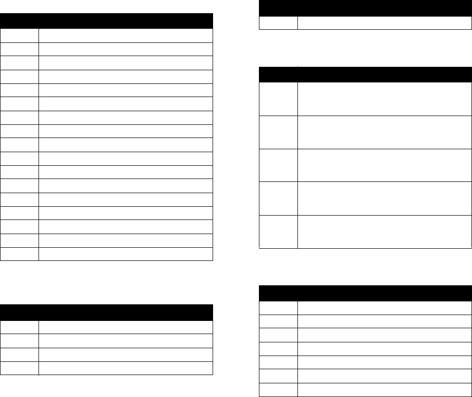
The following warnings are for the setup, use, grounding, maintenance, and repair of this equipment. The exclama-
tion point symbol alerts you to a general warning and the hazard symbol refers to procedure-specific risk. Refer back
to these warnings. Additional, product-specific warnings may be found throughout the body of this manual where
applicable.
WARNING
ELECTRIC SHOCK HAZARD
This equipment must be grounded. Improper grounding, setup, or usage of the system can cause elec-
tric shock.
• Turn off and disconnect power at main switch before disconnecting any cables and before servicing
equipment.
• Connect only to grounded power source.
• All electrical wiring must be done by a qualified electrician and comply with all local codes and reg-
ulations.
TOXIC FLUID OR FUMES HAZARD
Toxic fluids or fumes can cause serious injury or death if splashed in the eyes or on skin, inhaled, or
swallowed.
• Read MSDSs to know the specific hazards of the fluids you are using.
• Store hazardous fluid in approved containers, and dispose of it according to applicable guidelines.
• Always wear chemically impermeable gloves when spraying, dispensing, or cleaning equipment.
PERSONAL PROTECTIVE EQUIPMENT
You must wear appropriate protective equipment when operating, servicing, or when in the operating
area of the equipment to help protect you from serious injury, including eye injury, hearing loss, inhala-
tion of toxic fumes, and burns. This equipment includes but is not limited to:
• Protective eyewear, and hearing protection.
• Respirators, protective clothing, and gloves as recommended by the fluid and solvent manufacturer.
+
SKIN INJECTION HAZARD
High-pressure fluid from dispensing device, hose leaks, or ruptured components will pierce skin. This
may look like just a cut, but it is a serious injury that can result in amputation. Get immediate surgical
treatment.
• Do not point dispensing device at anyone or at any part of the body.
• Do not put your hand over the fluid outlet.
• Do not stop or deflect leaks with your hand, body, glove, or rag.
• Follow the Pressure Relief Procedure when you stop dispensing and before cleaning, checking,
or servicing equipment.
• Tighten all fluid connections before operating the equipment.
• Check hoses and couplings daily. Replace worn or damaged parts immediately.
Warnings
313997W 19
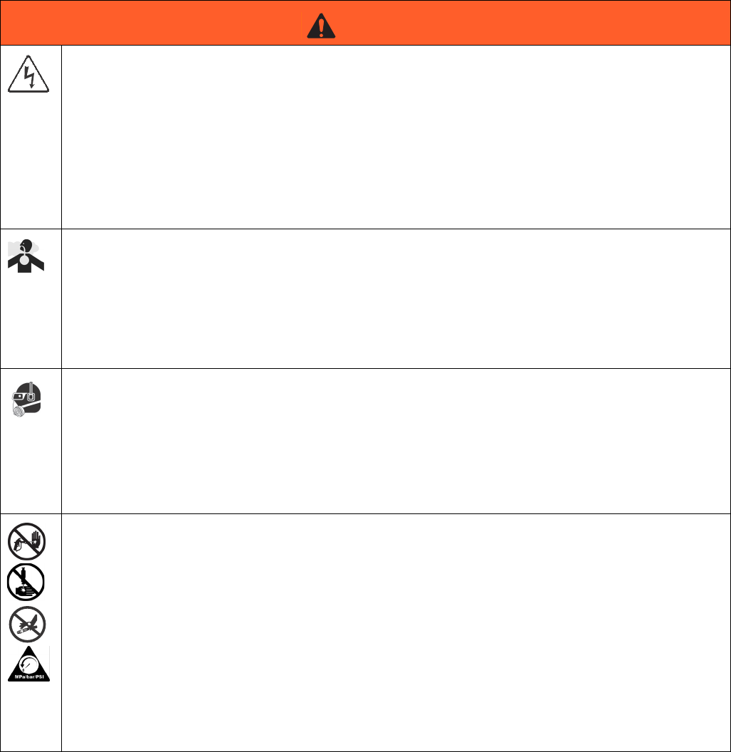
FIRE AND EXPLOSION HAZARD
Flammable fumes, such as solvent and paint fumes, in work area can ignite or explode. To help prevent
fire and explosion:
• Use equipment only in well ventilated area.
• Eliminate all ignition sources; such as pilot lights, cigarettes, portable electric lamps, and plastic
drop cloths (potential static arc).
• Keep work area free of debris, including solvent, rags and gasoline.
• Do not plug or unplug power cords, or turn power or light switches on or off when flammable fumes
are present.
• Ground all equipment in the work area. See Grounding instructions.
• Use only grounded hoses.
• Hold gun firmly to side of grounded pail when triggering into pail.
• If there is static sparking or you feel a shock, stop operation immediately. Do not use equipment
until you identify and correct the problem.
• Keep a working fire extinguisher in the work area.
PRESSURIZED EQUIPMENT HAZARD
Fluid from the gun/dispense valve, leaks, or ruptured components can splash in the eyes or on skin and
cause serious injury.
• Follow the Pressure Relief Procedure when you stop spraying and before cleaning, checking, or
servicing equipment.
• Tighten all fluid connections before operating the equipment.
• Check hoses, tubes, and couplings daily. Replace worn or damaged parts immediately.
EQUIPMENT MISUSE HAZARD
Misuse can cause death or serious injury.
• Do not operate the unit when fatigued or under the influence of drugs or alcohol.
• Do not exceed the maximum working pressure or temperature rating of the lowest rated system
component. See Technical Data in all equipment manuals.
• Use fluids and solvents that are compatible with equipment wetted parts. See Technical Data in all
equipment manuals. Read fluid and solvent manufacturer’s warnings. For complete information
about your material, request MSDS from distributor or retailer.
• Do not leave the work area while equipment is energized or under pressure. Turn off all equipment
and follow the Pressure Relief Procedure when equipment is not in use.
• Check equipment daily. Repair or replace worn or damaged parts immediately with genuine manu-
facturer’s replacement parts only.
• Do not alter or modify equipment.
• Use equipment only for its intended purpose. Call your distributor for information.
• Route hoses and cables away from traffic areas, sharp edges, moving parts, and hot surfaces.
• Do not kink or over bend hoses or use hoses to pull equipment.
• Keep children and animals away from work area.
• Comply with all applicable safety regulations.
WARNING
Important Two-Component Material Information
20 313997W
Important Two-Component Material Information
Isocyanate Conditions
Material Self-ignition
Keep Components A (Red) and
B(Blue) Separate
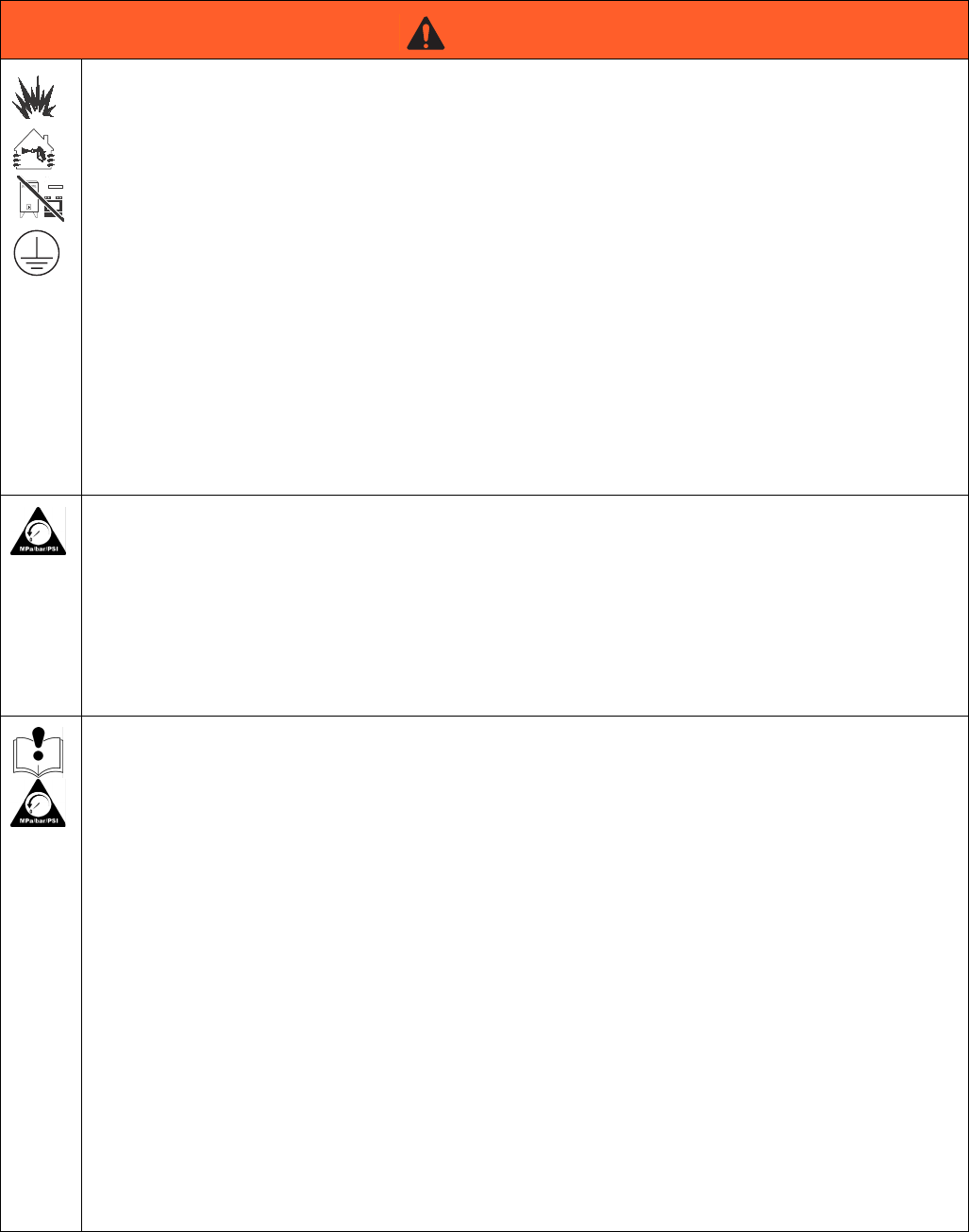
MOVING PARTS HAZARD
Moving parts can pinch, cut or amputate fingers and other body parts.
• Keep clear of moving parts.
• Do not operate equipment with protective guards or covers removed.
• Pressurized equipment can start without warning. Before checking, moving, or servicing equip-
ment, follow the Pressure Relief Procedure and disconnect all power sources.
BURN HAZARD
Equipment surfaces and fluid that’s heated can become very hot during operation. To avoid severe
burns:
• Do not touch hot fluid or equipment.
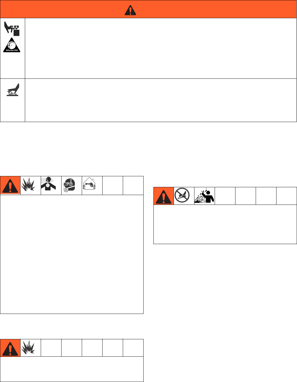
WARNING
Spraying or dispensing materials containing isocya-
nates creates potentially harmful mists, vapors, and
atomized particulates.
Read material manufacturer’s warnings and material
MSDS to know specific hazards and precautions
related to isocyanates.
Prevent inhalation of isocyanate mists, vapors, and
atomized particulates by providing sufficient ventila-
tion in the work area. If sufficient ventilation is not
available, a supplied-air respirator is required for
everyone in the work area.
To prevent contact with isocyanates, appropriate per-
sonal protective equipment, including chemically
impermeable gloves, boots, aprons, and goggles, is
also required for everyone in the work area.
Some materials may become self-igniting if applied
too thickly. Read material manufacturer’s warnings
and material MSDS.
Cross-contamination can result in cured material in
fluid lines which could cause serious injury or dam-
age equipment. To prevent cross-contamination of
the equipment’s wetted parts, never interchange
component A (Red) and component B (Blue) parts.
A (Red) and B (Blue) Components
313997W 21
Moisture Sensitivity of
Isocyanates
Isocyanates (ISO) are catalysts used in two component
foam and polyurea coatings. ISO will react with moisture
(such as humidity) to form small, hard, abrasive crystals,
which become suspended in the fluid. Eventually a film
will form on the surface and the ISO will begin to gel,
increasing in viscosity. If used, this partially cured ISO
will reduce performance and the life of all wetted parts.
NOTE: The amount of film formation and rate of crystal-
lization varies depending on the blend of ISO, the
humidity, and the temperature.
To prevent exposing ISO to moisture:
• Always use a sealed container with a desiccant
dryer in the vent, or a nitrogen atmosphere. Never
store ISO in an open container.
• Keep the ISO lube pump reservoir (if installed) filled
with IsoGuard Select, part 24F516. The lubricant
creates a barrier between the ISO and the atmo-
sphere.
• Use moisture-proof hoses specifically designed for
ISO, such as those supplied with your system.
• Never use reclaimed solvents, which may contain
moisture. Always keep solvent containers closed
when not in use.
• Never use solvent on one side if it has been contam-
inated from the other side.
• Always lubricate threaded parts with ISO pump oil
or grease when reassembling.
Foam Resins with 245 fa
Blowing Agents
Some foam blowing agents will froth at temperatures
above 90°F (33°C) when not under pressure, especially
if agitated. To reduce frothing, minimize preheating in a
circulation system.
Changing Materials
• When changing materials, flush the equipment mul-
tiple times to ensure it is thoroughly clean.
• Always clean the fluid inlet strainers after flushing.
• Check with your material manufacturer for chemical
compatibility.
• Most materials use ISO on the A (Red) side, but
some use ISO on the B (Blue) side. See the follow-
ing section.
A (Red) and B (Blue) Components
IMPORTANT!
Material suppliers can vary in how they refer to plural
component materials.
Be aware that when standing in front of the manifold on
proportioner:
• Component A (Red) is on the left side.
• Component B (Blue) is on the right side.
For all machines:
• The A (Red) side is intended for ISO, hardeners,
and catalysts.
• If one of the materials being used is moisture-sensi-
tive, that material should always be in the A (Red)
side.
• The B (Blue) side is intended for polyols, resins, and
bases.
NOTE: For machines with material volume ratios other
than 1:1, the higher volume side is typically the B (Blue)
side.

A (Red) and B (Blue) Components
22 313997W
Typical Installation
313997W 23
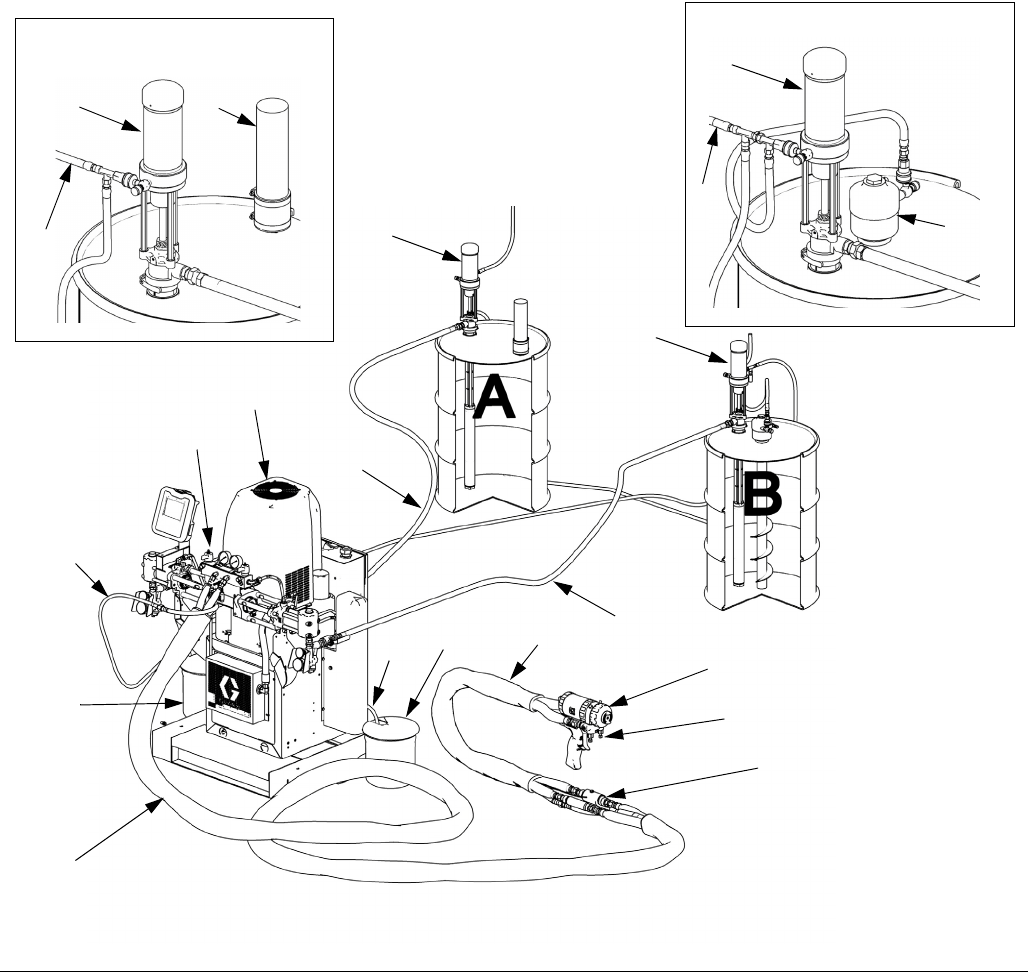
Typical Installation
Key:
A HFR Unit (see FIG. 2, page 25)
BHose
C Fluid Temperature Sensor (FTS); 2x, 1 for each hose
D Whip Hose
E Dispense Gun
F Gun Air Supply Hose
G Feed Pump Air Supply Lines
H Waste Container
J Fluid Supply Lines
K Feed Pumps
L Agitator
M Desiccant Dryer
N Bleed Lines
P Fluid Manifold
FIG. 1
B
C*
D
E
F
K
J
ti7821a3
* Shown exposed for clarity.
Wrap with tape during operation.
J
A
K
P
NH
L
G
K
B (Blue) Side Supply Detail
G
KM
A (Red) Side Supply Detail
ti7821a2
ti14720a
P
H
Component Identification
24 313997W
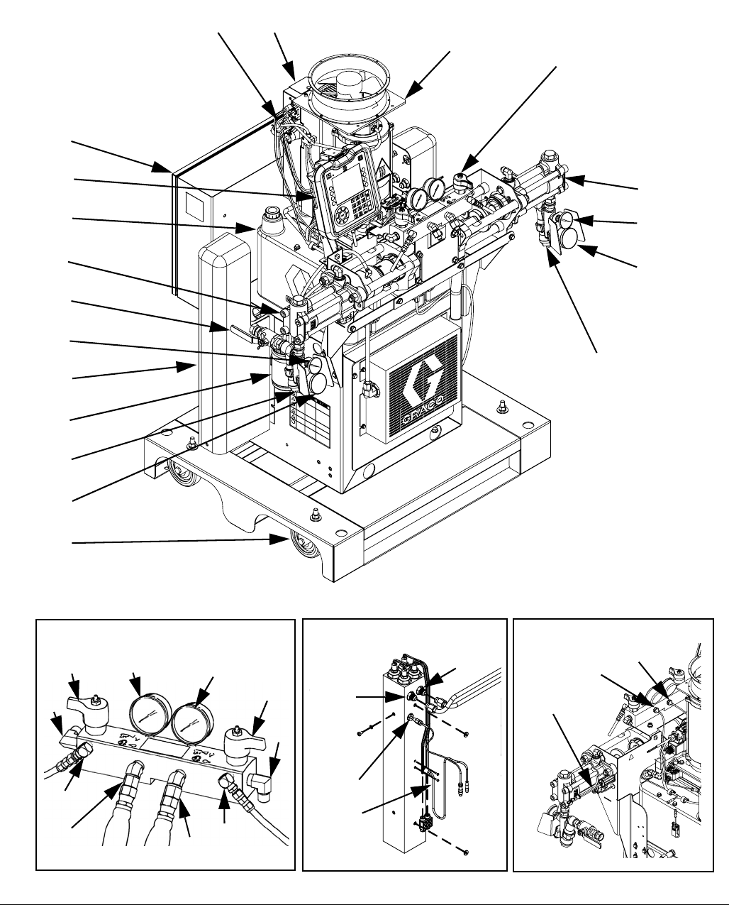
Component Identification
Key for FIG. 2.
AA Advanced Display Module (see page 30)
BA Component A (Red) Pressure Relief Outlet
BB Component B (Blue) Pressure Relief Outlet
CO Base and Casters (Optional)
FA Component A (Red) Fluid Manifold Inlet (on left side of
manifold block)
FB Component B (Blue) Fluid Manifold Inlet
FM HFR Fluid Manifold
FP Feed Inlet Pressure Gauge
FS Feed Inlet Strainer (standard filter size is 20 mesh)
FT Feed Inlet Temperature Gauge (heated models only)
FV Feed Inlet Valve (A (Red) side shown)
GA Component A (Red) Outlet Pressure Gauge
GB Component B (Blue) Outlet Pressure Gauge
HA Component A (Red) Hose Connection (from feed to gun
or mix head)
HB Component B (Blue) Hose Connection (from feed to gun
or mix head)
HP Hydraulic Power Pack Assembly
HT Hydraulic Tank
LR IsoGuard Select Fluid Reservoir
LS Pumpline Linear Sensor
MA Motor Control Module, see page 28
MP Main Power Switch
PA Component A (Red) Pump
PB Component B (Blue) Pump
PD Power Distribution Box
PH Primary Heater
PI Primary Heater Fluid Inlet
PO Primary Heater Fluid Outlet
PR Primary Heater RTD
PS Primary Heater Overtemperature Switch
SA Component A (Red) PRESSURE RELIEF/DISPENSE
Valve
SB Component B (Blue) PRESSURE RELIEF/DISPENSE
Valve
TA Component A (Red) Pressure Transducer
TB Component B (Blue) Pressure Transducer
TC High Power Temperature Control Module (not shown, see
page 34)
Component Identification
313997W 25
FIG. 2: Component Identification, Heated Model shown with shrouds removed
ti9880a1
GA GB
SB
FB
BB
HB
HA
BA
FA
SA
Fluid Manifold (FM) Detail
LR
PA
PB
FV
FT
FP
FS
AA
HP
FM
PD
HT
MA
FS
FP
FT
MP
PH
TA
TB
LS
PI
PO
PR
PS
Rear View
Primary Heater (PH) Detail,
B (Blue) side shown
24C352_313998_3g
24C327_313998_1e 24C352_313998_4e
CO
Component Identification
26 313997W
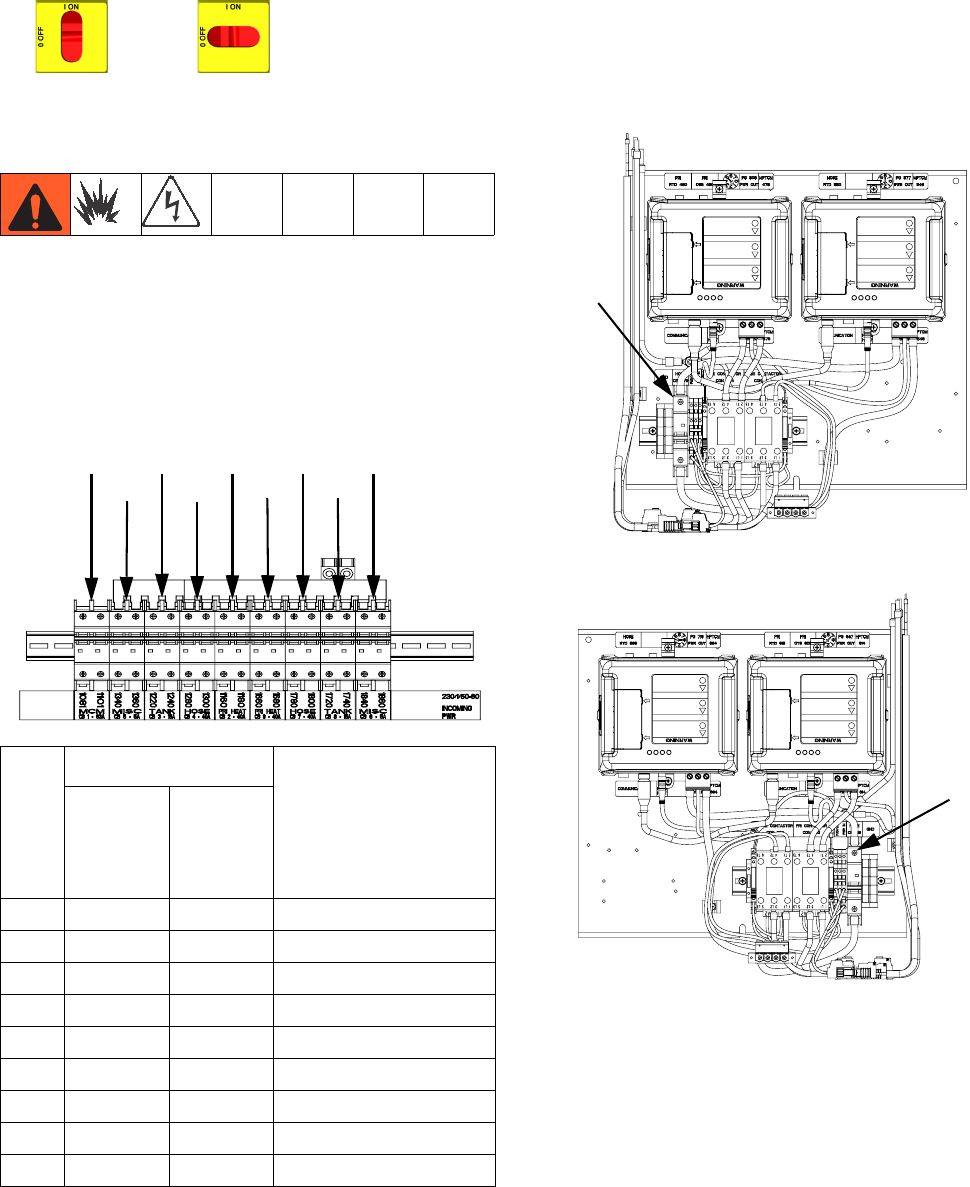
Main Power Switch
Located on top of the power distribution box, see
page 25. The main power switch turns power
ON and OFF . The main power switch
does not turn pumps or heat zones on.
Circuit Breakers
Most circuit breakers are located inside the power distri-
bution box. The main block of circuit breakers in the
power distribution box is shown below, with detailed
information in the following table. For more information
about items in the power distribution box, see power dis-
tribution box manual for more information.
Additional circuit breakers for protection of the second-
ary side of the heated hose transformer are located
inside the frame. See the parts list for the installed pri-
mary/hose heat option. See Ref. 5 of the product config-
urator code for your machine to determine which
primary/hose heat option is installed. See Product Con-
figurator on page 5.
Ref.
Size
Component
230V/
1 phase,
400V/
3 phase
230V/
3 phase
CB1 63A 30A Motor Control Module
CB2 40A 40A Primary Heater A
CB3 15A 15A Tank Heat A
CB4 40A 40A Hose Heat A
CB5 5A 5A Miscellaneous
CB6 5A 5A Miscellaneous
CB7 40A 40A Hose Heat B
CB8 15A 15A Tank Heat B
CB9 40A 40A Primary Heater B
CB1
CB5 CB4
CB2CB3
CB9
CB7 CB6
CB8
24C681_313998_1e
CB579
CB718
B (Blue)
Left Side from Rear View
A (Red)
Right Side from Rear View
24C332_313998_3f
24C332_313998_6f
Component Identification
313997W 27
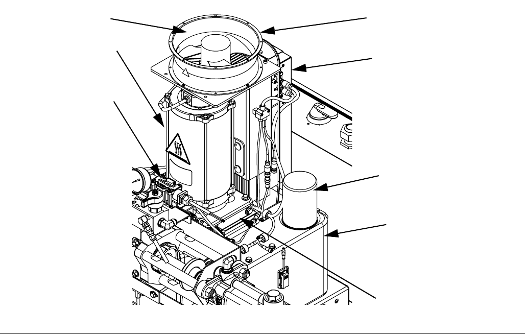
Hydraulic Power Pack
Key:
DA 8 Gallon Hydraulic Oil Reservoir (see Technical Data on
page 108 for specifications)
DB Electric Motor
DC Dipstick (not shown, located at rear left of hydraulic tank)
DD Hydraulic Housing
DE Directional Valve
DF Motor Control Module (see page 28)
DG Fan
DH Oil Filter
DJ Shroud (not shown, removed for clarity)
DK Air Inlet Filter
FIG. 3
DA
DG
DE
DD
DH
DB
DF
24C352_313998_2g
DK
Component Identification
28 313997W
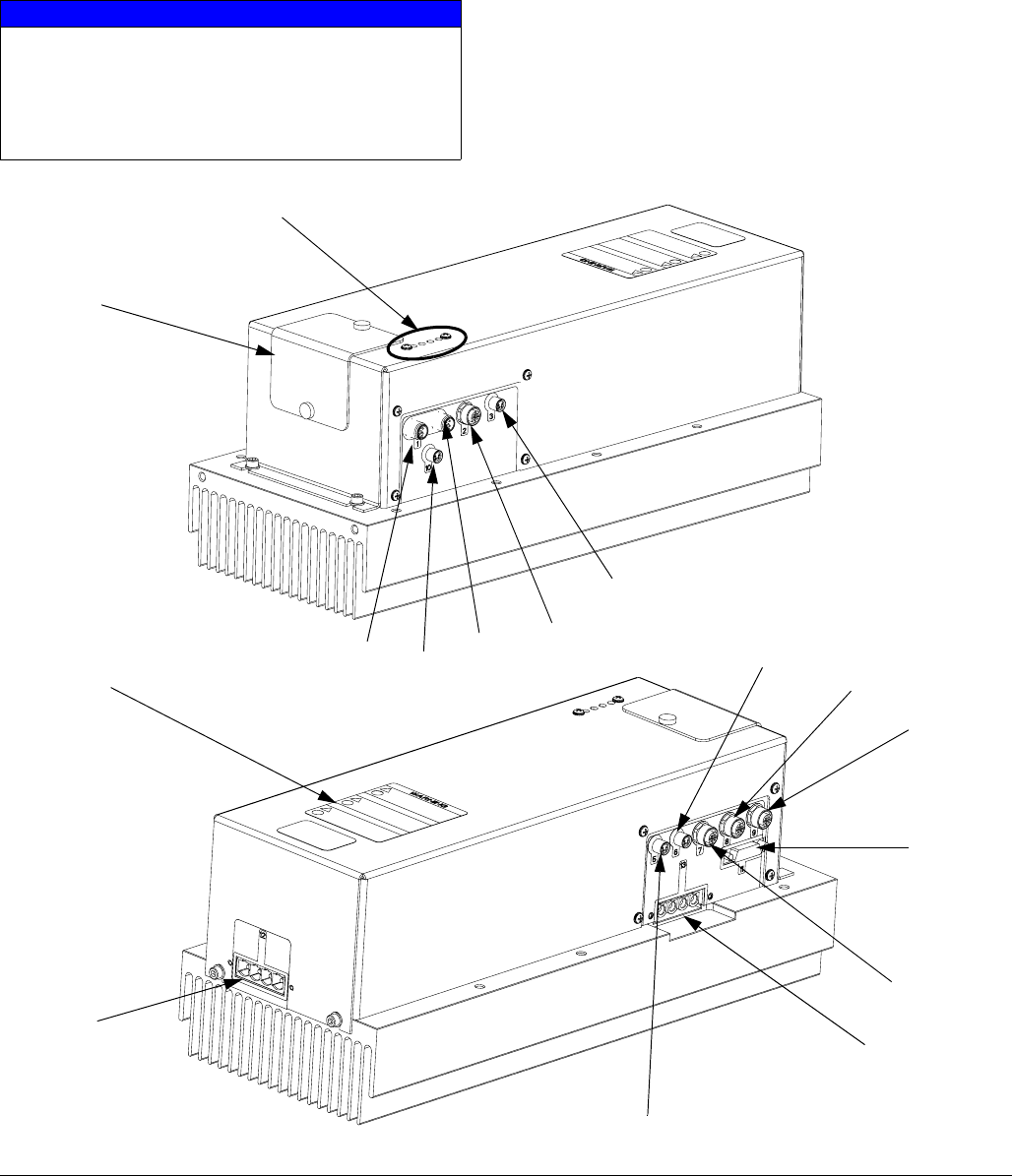
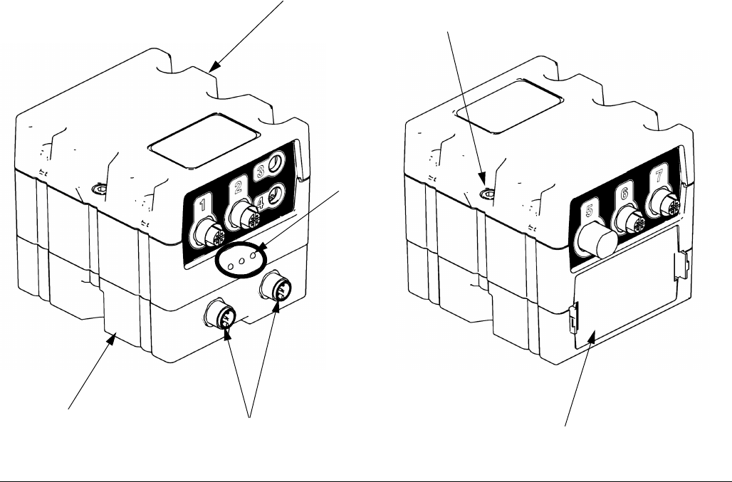
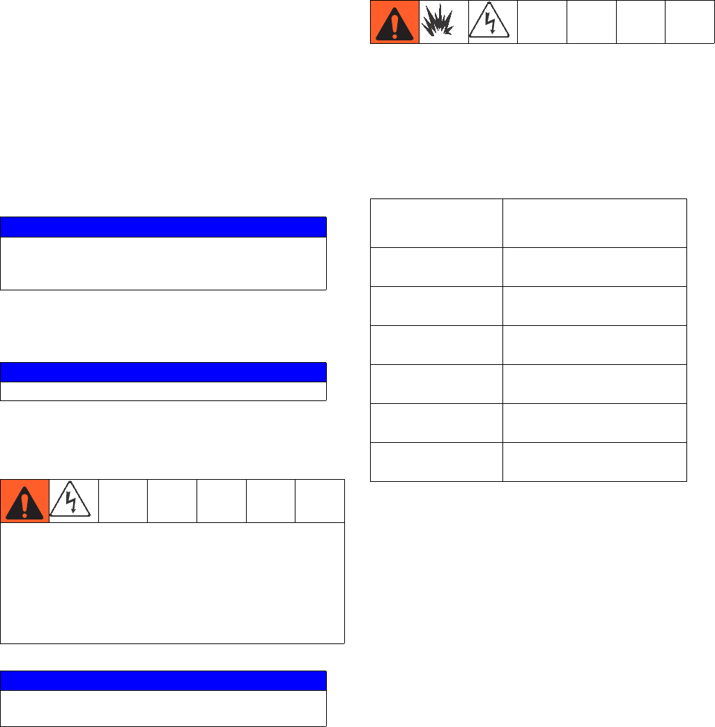
Motor Control Module (MCM)
For MCM location, see reference MA in FIG. 2 on
page 25. When installed, the end of the MCM with the
power input connection (12) faces down and the end
with the access cover (A) faces up.
The Motor Control Module uses an 8-position selector
switch to set the system maximum working pressure.
NOTICE
If the Motor Control Module is replaced, the selec-
tor switch must be set prior to initial startup of the
Motor Control Module or damage may occur. See
HFR Repair manual for details, see Related Man-
uals on page 3.
FIG. 4: MCM Component Identification
A
r_257396_3b9905_01b
r_257396_3b9905_03b
C
12
B
13
1A
11
1B
5
7
6
8
9
10
2
3

Component Identification
313997W 29
Ref Description
A Access Cover
BLEDs
C Warning Label
1A, 1B CAN Connections
2 Three-way Splitter to: Oil Low Level
Sensor, Dispense Valve Solenoid, and
Footswitch
3 Oil Temperature Sensor
5 Electric Motor Temperature Sensor
6LVDT
7 Three-way Splitter to:
Hydraulic Directional Valve,
Oil Overtemperature Switch
8 Pressure Transducer B (Blue) side
9 Pressure Transducer A (Red) side
10 Not used
11 Motor Position Sensor
12 MCM Power Input Connection
13 Motor Power Connection
Component Identification
30 313997W
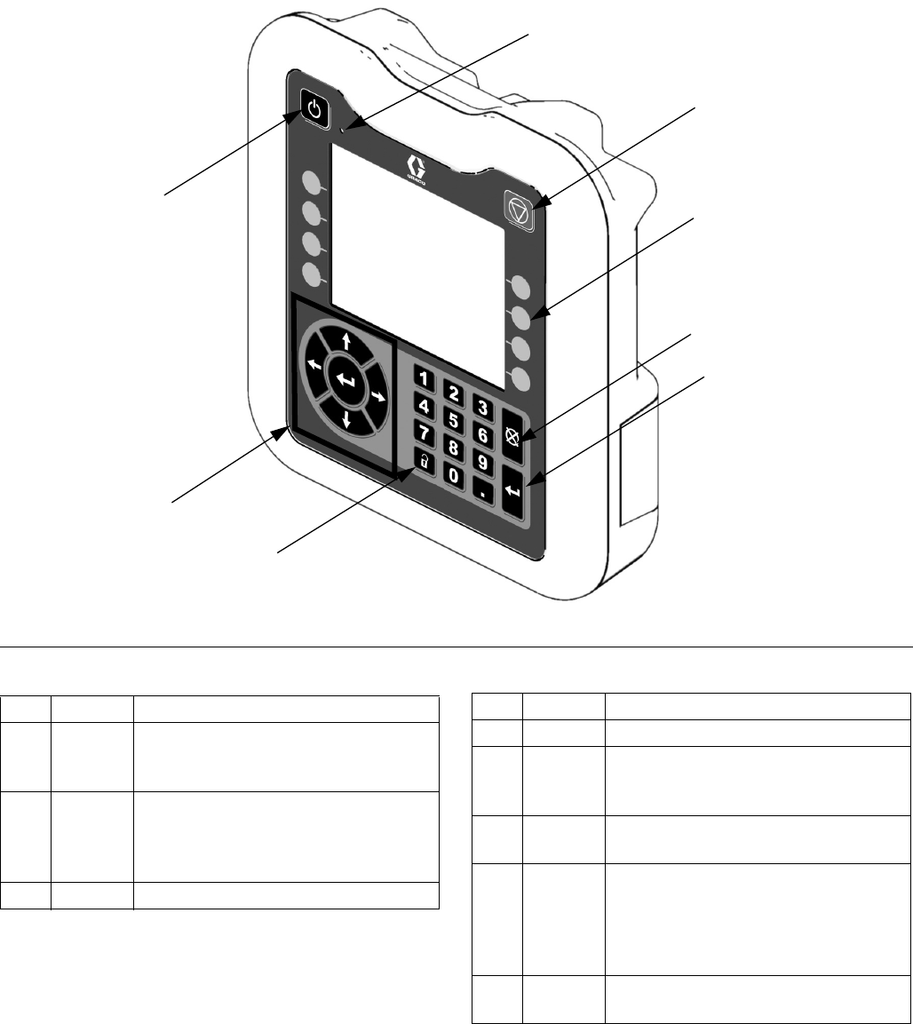
Advanced Display Module (ADM)
User Interface
Buttons
FIG. 5: ADM Component Identification - Front
TI12362a1
CA
CB
CC
CE
CH
CG
CF
CD
Ref. Button Function
CA System
enable/
disable
Enables/disables system. When sys-
tem is disabled, temperature control
and dispense operation are disabled.
CB System
Status
Indicator
Light
Displays system status. See System
Status Indicator (CB) Conditions on
page 31 for details.
CC Stop Stops all system processes.
CD Soft Keys Defined by application using ADM.
CE Cancel Cancel a selection or number entry
while in the process of entering a
number or making a selection.
CF Enter Acknowledge changing a value or
making a selection.
CG Lock/Set
up
Toggle between run and setup
screens. If setup screens are pass-
word protected, button toggles
between run and password entry
screen.
CH Naviga-
tion
Navigate within a screen or to a new
screen.
Ref. Button Function
Component Identification
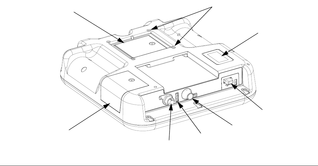
313997W 31
Key:
CJ Flat Panel Mount
CK Model Number
CL USB Module Interface
CM CAN Cable Connections
CN Module Status LEDs
CP Accessory Cable Connections
CR Token Access Cover
CS Battery Access Cover
System Status Indicator (CB) Conditions
Green Solid - Run Mode, System On
Green Flashing - Setup Mode, System On
Yellow Solid - Run Mode, System Off
Yellow Flashing - Setup Mode, System Off
FIG. 6: ADM Component Identification - Rear
CR
CK
CJ
CL
CP
CN
CM
CS
r_24E451_3B9900_1a
Component Identification
32 313997W
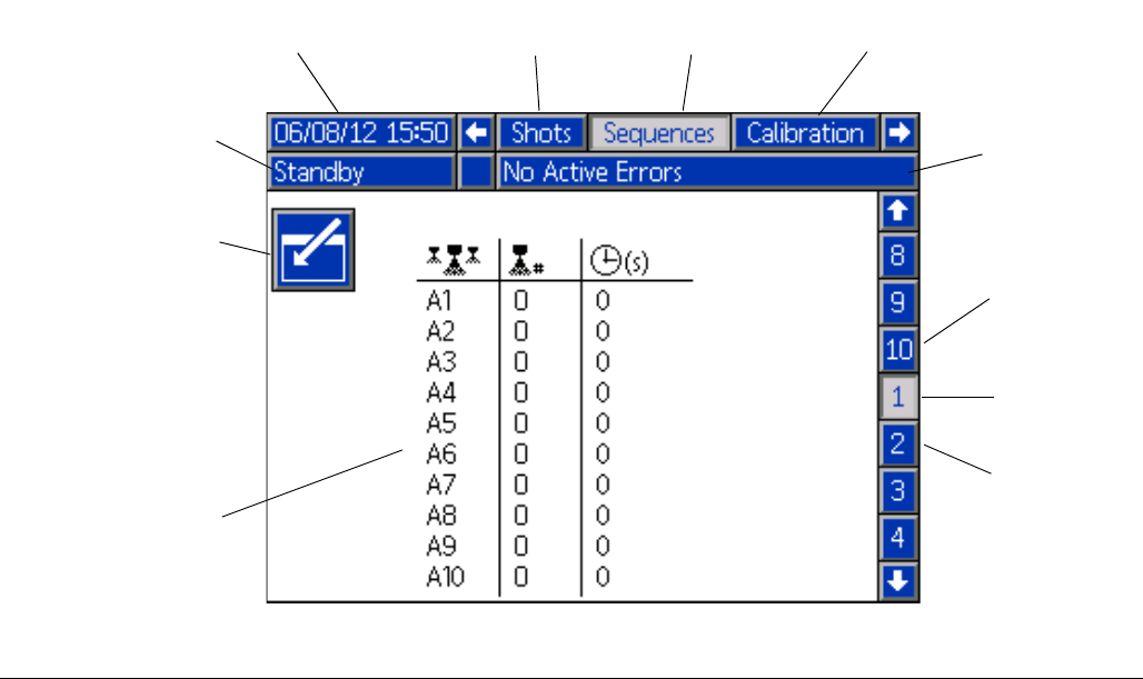
Main Display Components
The following figure calls out the navigational, status, and general informational components of each screen. For
details regarding the user interface display see Advanced Display Module (ADM) Operation, page 46.
FIG. 7: Main Display Components
Current date and time Current screen
Enter/Exit screen
Previous screen Next screen
Function display
Current
screen no.
Next
screen no.
Previous
screen no.
Mode Faults, Status
Component Identification
313997W 33
Fluid Control Module (FCM)
Key:
A Fluid Control Module
BBase
C Module Connection Screws
D Access Cover
E Module Status LEDs
F CAN Connectors
FIG. 8:
ti12337a1 ti12336a1
A
E
B
C
D
F
Component Identification
34 313997W
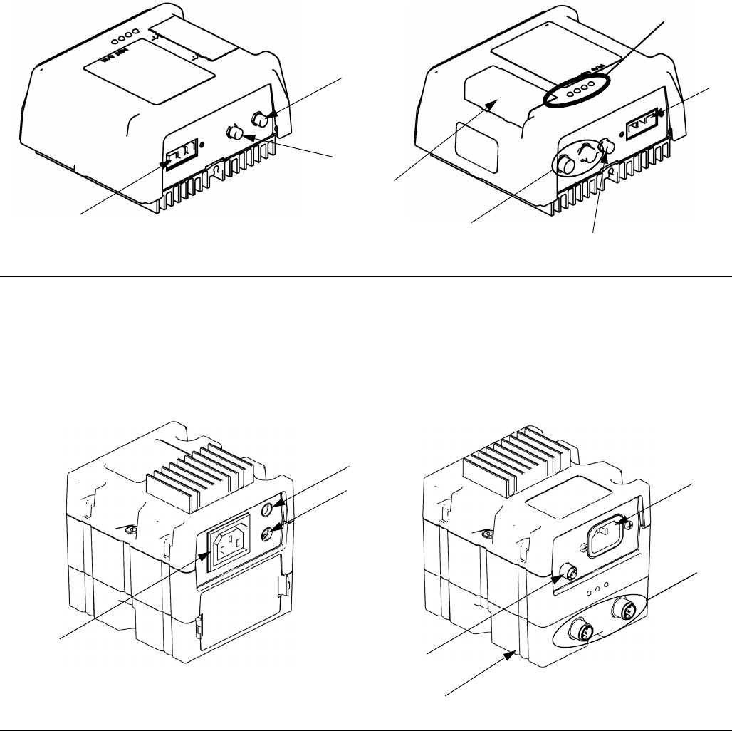
Temperature Control Module (Heated HFR Only)
Key:
1 Overtemperature Switch Connection (primary heaters
only)
2 RTD Temperature Sensor Connection
3 Output Power Connection
4 DC Output Connection
5 Input Power Connection
6 CAN Connections
7 Rotary Selector Switch, Token Access
1 Overtemperature Switch Connection
2 RTD Temperature Sensor Connection
3 Output Power Connection
4 DC Output Connection
5 Input Power Connection
6 CAN Connections
7Base
FIG. 9: High Power Temperature Control Module Sensor Connections
1
2
3
5
4
6
LED
Signals
7
ti12352a1 ti12353a1
FIG. 10: Low Power Module Cable Connections
1
2
3
4
5
6
7
ti12356a1 ti12357a1
Component Identification
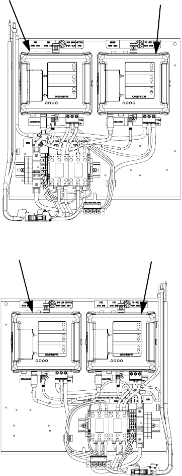
313997W 35
Heat Control Zone Selection
(Heated models only)
The HFR unit supports 4 independent temperature con-
trol zones. The high power temperature control modules
are located inside the frame below the hydraulic power
pack.
Hose Heater B (Blue) Primary Heater B (Blue)
Hose Heater A (Red)
Primary Heater A (Red)
Right Side from
Rear View
Left Side from
Rear View
24C332_313998_3f
24C332_313998_6f
Component Identification
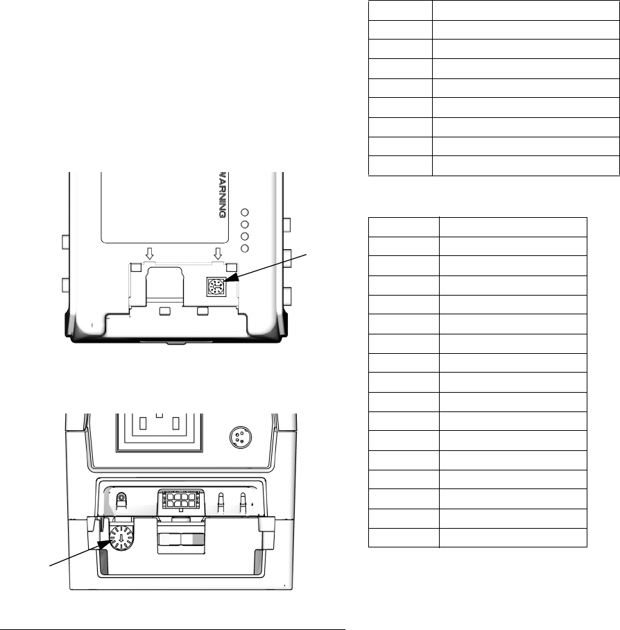
36 313997W
Adjust Rotary Switch
The rotary switch setting indicates which zone the tem-
perature control module will control in the system. The
high power module uses an 8-position rotary switch. The
low power module uses a16-position rotary switch.
Set the rotary switch (S) to the specific selection accord-
ing to the settings listed in the following tables.
High Power Module Rotary Switch Settings
Low Power Module Rotary Switch Settings
FIG. 11
High Power Module Rotary Switch Location
Low Power Module Rotary Switch Location
S
S
ti12360a
ti12361a
Setting Zone
0Not Used
1 B (Blue) Primary Heat
2 B (Blue) Hose Heat
3 A (Red) Primary Heat
4 A (Red) Hose Heat
5Not Used
6Not Used
7Not Used
Setting Zone
0Not Used
1Not Used
2Not Used
3Not Used
4Not Used
5 B (Blue) Tank Heater
6 A (Red) Tank Heater
7 B (Blue) Chiller
8 A (Red) Chiller
9Not Used
ANot Used
BNot Used
CNot Used
DNot Used
ENot Used
FNot Used
Dispense Valves Overview
313997W 37
Dispense Valves Overview
Three types of dispense valves can be used with the
HFR system:
• Stall-at-pressure
• Solenoid controlled
• Hydraulically actuated and recirculating
The P2 Gun and Fusion Gun are examples of
stall-at-pressure dispense valves. When not dispensing,
the fluid in the chemical lines are fully pressurized.
When using a stall-to-pressure dispense valve, a foot-
switch cannot be used. Any signals sent from a foot-
switch will be ignored.
The EP Gun and MD2 Valve are examples of solenoid
controlled dispense valves. When the trigger is pulled
the signal requests the dispense to start. When the
machine sees the signal, fluid rises to dispensing pres-
sure and the valve is opened to begin dispensing. When
the trigger is released, the solenoid signals that the dis-
pense is finished.
The L-Head, S-Head, and GX-16 are examples of
hydraulically actuated, recirculating dispense valves.
When not dispensing, material is recirculated to main-
tain temperature and pressure. Opening and closing the
valve is controlled hydraulically which leads to faster
actuation and more accurate dispenses.
Setup
38 313997W
Setup
Perform this setup procedure to secure all necessary
machine connections for machine operation.
1. Locate HFR.
a. Locate HFR on a level surface. See Dimen-
sions on page 110 for space requirements.
b. Anchor the HFR to the floor (suggested
anchors: McMaster Carr anchor, 92403A400).
See Dimensions, page 110, for bolt locations. If
machine mobility is required, purchase Mobile
Pallet Base with Casters Kit, 24P090.
c. Do not expose HFR to rain.
2. Electrical requirements. See Models on page 4
for detailed electrical requirements information.
3. Connect electrical cord.
NOTE: See Power Line Voltage Surges information on
page 39.
NOTE: Power cord is not supplied. See the following
table.
† Residual Current Device (RCD) must be rated at
300 mA if installed.
Electrical Cord Wires by Model
230V, 1 phase: L1, L2, GND
230V, 3 phase: L1, L2, L3, GND
400V, 3 phase: L1, L2, L3, N, GND
Typical Voltage Readings
230V, 1 phase:
L1-L2: 230V
L1 or L2-G: 115V
230V, 3 phase (delta high leg):
L1-L2, L2-L3, L3-L1: 230V
L1-G, L3-G: 115V
L2-G: 208V
400V, 3 phase (Y / wye):
L1-L2, L2-L3, L3-L1: 400V
L1-N, L2-N, L3-N: 230V
L1-G, L2-G, L3-G: 230V
NOTICE
To avoid tipping the machine and personal injury, do
not attach wheels directly to the standard HFR
mounting brackets.
NOTICE
Bolt HFR to original shipping pallet before lifting.
Installing this equipment requires access to parts
which may cause electric shock or other serious injury
if work is not performed properly. Have a qualified
electrician connect power and ground to main power
switch terminals, see step 3 in this setup procedure.
All electrical wiring must be done by a qualified electri-
cian and comply with all local codes and regulations.
NOTICE
Never connect to 480V, 3 phase power. Severe
equipment damage will occur.
Table 1: Power Cord Requirements
Model
Cord Requirements
AWG (mm2)
Non-Heated HFR,
230V, 1 phase
6 (13.3), 2 wire + ground
Non-Heated HFR,
230V, 3 phase
8 (8.4), 3 wire + ground
Non-Heated HFR,
400V, 3 phase
6 (13.3), 4 wire + ground †
Heated HFR,
230V, 1 phase
1 (42.4), 2 wire + ground
Heated HFR,
230V, 3 phase
4 (21.2), 3 wire + ground
Heated HFR,
400V, 3 phase
4 (21.2), 4 wire + ground †
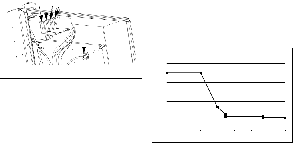
Setup
313997W 39
Use 5/32 or 4 mm hex allen wrench to connect the two
or three power leads to L1, L2, and L3, as applicable.
Connect green to ground (GND).
Power Line Voltage Surges
Power conversion equipment can be sensitive to voltage
fluctuations on incoming power. The Motor Control Mod-
ule falls under the category of power conversion equip-
ment because energy is stored on a capacitive bus and
then modulated to control a brushless motor. Engi-
neered design takes this into account and withstands a
wide range of conditions, but it is possible for supplied
power to occasionally fall outside the tolerable range in
industrial plants with high-amperage reactive pulsed
loads such as welding equipment. If the tolerable range
is exceeded, an overvoltage condition is flagged and the
system will shut down in an alarm state to protect itself
and alert the user of unstable power. Excessive or
repeated overvoltage may permanently damage hard-
ware.
The MAX-HOLD feature on a multimeter can be used to
determine peak DC voltage on the line. DC is the proper
setting, as opposed to AC, because peak voltage is the
critical parameter that affects the DC voltage level
stored on the capacitive bus in power conversion equip-
ment. Reading should not regularly exceed approxi-
mately 400VDC to avoid tripping the 420VDC alarm
level in the Motor Control Module. If power quality is sus-
pect, power conditioning or isolation of the device(s)
causing poor power quality is recommended. Consult a
qualified electrician if there are any concerns about the
available power supply.
Power Line Test Steps with Multimeter
a. Set multimeter to “DC voltage”.
b. Connect multimeter probes to supplied power
line.
c. Press “Min Max” successively to show the peak
positive and negative DC voltages.
d. Confirm readings do not exceed 400VDC
(Motor Control Module alarm issued at
420VDC).
The chart below shows the permissible magnitude and
duration of temporary over-voltage events:
FIG. 12: 400V, 3 phase shown
r_24C686_313998_1a
L1L2L3N
GND
Maximum Permissible Transient Voltage Surges
* Constructed from ITIC 1996 curve, referenced by IEC 61000-2-4
1200Vac, 1697Vdc
264Vac, 373Vdc
336Vac, 475Vdc
288Vac, 407Vdc
480Vac, 679Vdc
<--1 MW Max Surge Power
<--150 KW Max Surge Power
<--50 KW Max Surge Power <--No Power Limit
0
200
400
600
800
1000
1200
1400
Time (seconds)
Voltage (Volts RMS)
0.000001 0.00001 0.0001 0.001 0.01 0.1 1 10
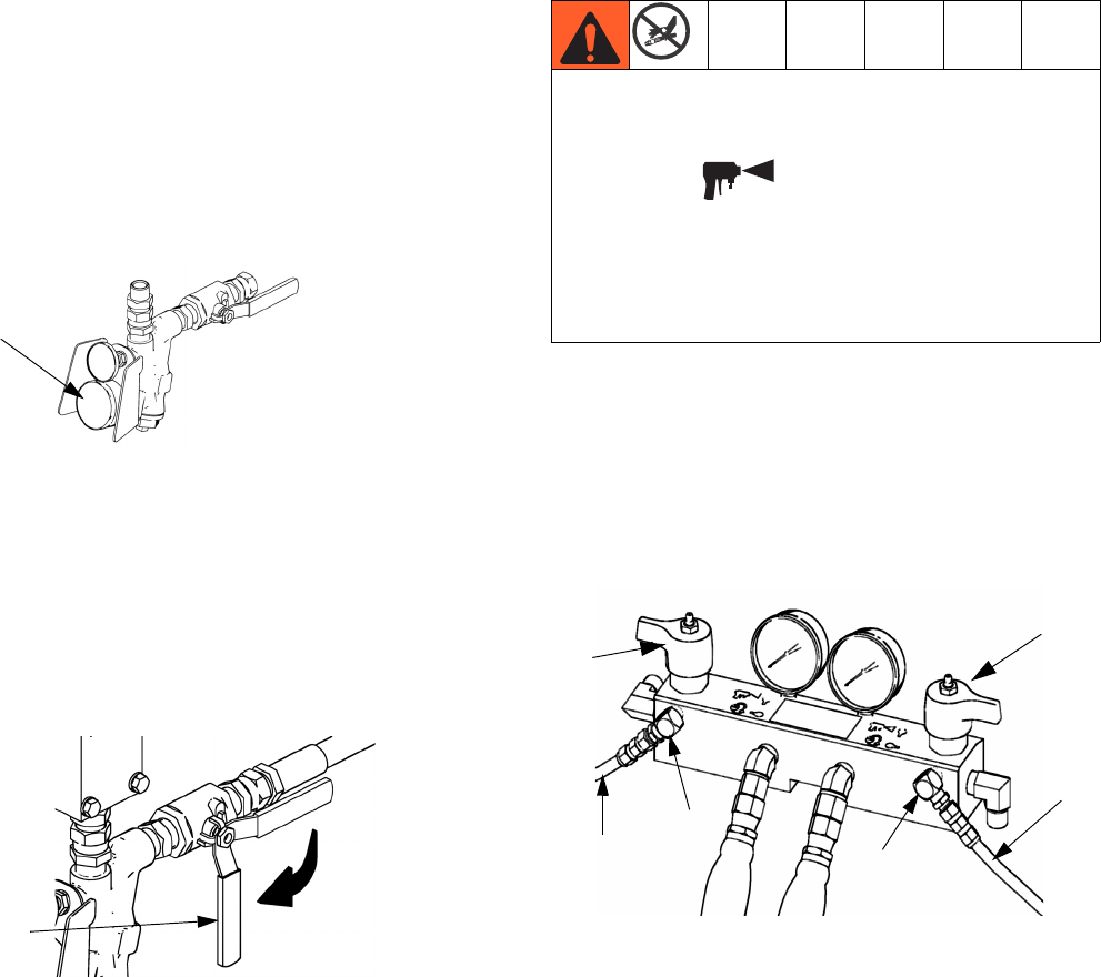
Setup
40 313997W
4. Connect feed lines
a. Install feed pumps (K) in component A (Red)
and B (Blue) supply drums. See FIG. 1 and FIG.
2, pages 23 and 25.
NOTE: A minimum feed pressure of 50 psi (0.35 MPa,
3.5 bar) is required at both feed inlet pressure gauges
(FP). Maximum feed pressure is 250 psi (1.75 MPa,
17.5 bar). Maintain A (Red) and B (Blue) feed pressures
within 10% of each other.
b. Seal component A (Red) drum and use desic-
cant dryer (M) in vent.
c. Install agitator (L) in component B (Blue) drum,
if necessary.
d. Ensure A (Red) and B (Blue) inlet valves (FV)
are closed.
NOTE:
Supply hoses from feed pumps should be 3/4 in.
(19 mm) ID minimum.
e. Connect and tighten component B (Blue) supply
hose to the 3/4 npt(f) swivel on the component B
(Blue) inlet valve.
f. Connect and tighten component A (Red) supply
hose to the 1/2 npt(f) swivel on the component A
(Red) inlet valve.
5. Connect pressure relief lines
a. Recommended: Connect high pressure hose
(R) to relief fittings (BA, BB) of both PRES-
SURE RELIEF/DISPENSE valves. Route hose
back to component A (Red) and B (Blue) drums.
See FIG. 1, page 23.
b. Alternately: Secure supplied bleed tubes (N) in
grounded, sealed waste containers (H). See
FIG. 1, page 23.
6. For Heated HFR models only, install Fluid Tem-
perature Sensor (FTS)
a. Install FTS between main hose and whip hose.
See Heated Hose manual for instructions.
FP
ti10006a1
ti9883a1
FV
Do not install shutoffs downstream of the PRESSURE
RELIEF/DISPENSE valve outlets (BA, BB). The
valves function as overpressure relief valves when set
to DISPENSE . Lines must be open so valves
can automatically relieve pressure when machine is
operating.
If circulating fluid back to the supply drums, use high
pressure hose rated to withstand the maximum work-
ing pressure of this equipment.
ti9880a1
BA
BB
R
R
SB
SA
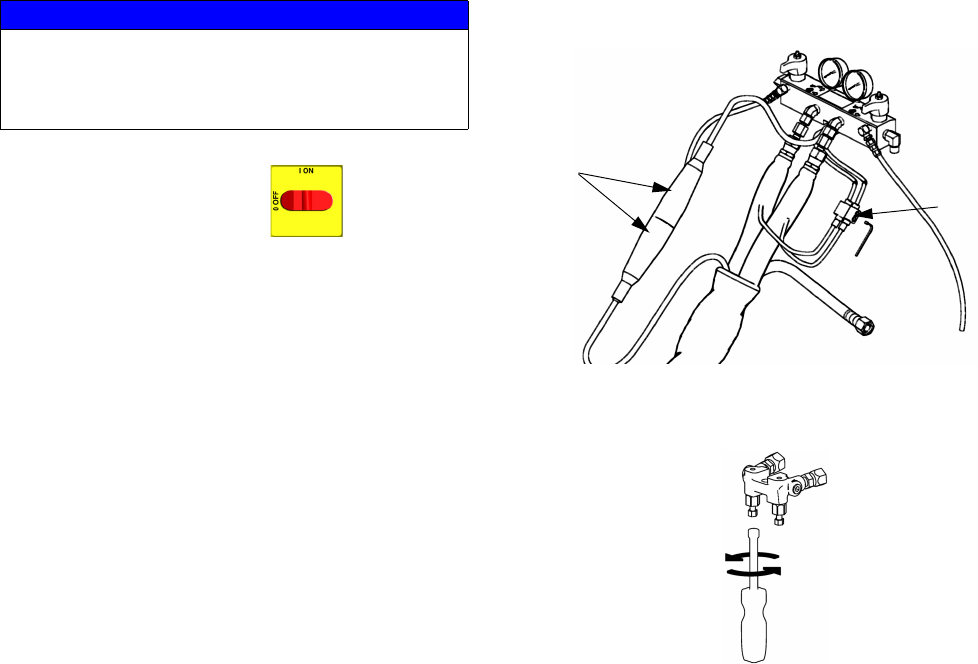
Setup
313997W 41
7. Connect heated hose monitor zones
NOTE: For Heated HFR models only, see Heated Hose
manual for detailed instructions on connecting heated
hoses.
a. Turn main power OFF .
b. For Heated HFR Models only, assemble
heated hose sections, FTS, and whip hose. See
Heated Hose manual 3A0237 for heated hose
connection details and illustrations for the vari-
ous types of heated hoses.
For Non-Heated HFR Models only, assemble
fluid supply hose sections and whip hose.
c. Connect A (Red) and B (Blue) hoses to A (Red)
and B (Blue) outlets on HFR fluid manifold (FM).
Hoses are color coded: red for component A,
blue for component B. Fittings are sized to pre-
vent connection errors.
NOTE: Gun fluid manifold hose adapters allow use of
1/4 in. and 3/8 in. ID fluid hoses. To use 1/2 in. (13 mm)
ID fluid hoses, remove adapters from gun fluid manifold
and install as needed to connect hose.
d. For Heated HFR Models only, connect
cables (Y). Connect electrical connectors (V).
Be sure cables have slack when hose bends.
Wrap cable and electrical connections with elec-
trical tape. See Heated Hose manual for heated
hose connection details and illustrations for the
various types of heated hoses.
8. For systems with a gun fluid manifold, close gun
fluid manifold valves A (Red) and B (blue).
NOTICE
For Heated HFR models only, the FTS (C) and
whip hose (D) must be used with heated hose. See
step 6 on page 40 for FTS installation. Hose length,
including whip hose, must be 10 ft (3 m) minimum.
ti9881a1
V
Y
ti2411a1
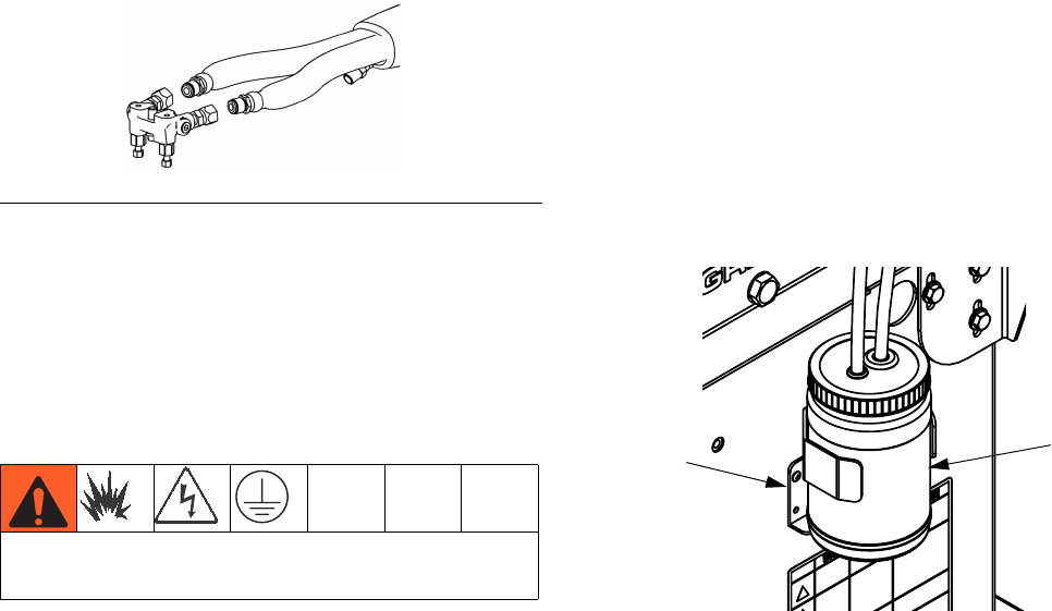
Setup
42 313997W
9. For models with an MD2 valve, connect whip
hose to MD2 valve component A (Red) and com-
ponent B (Blue) fluid inlets.
For models with a dispense gun, connect whip
hose to gun fluid manifold. Do not connect man-
ifold to gun. See FIG. 13.
10.Pressure check hose
See hose manual. Pressure check for leaks. If no leaks,
wrap hose and electrical connections to protect from
damage.
11.Ground system
a. HFR: grounded through power cord. See step 3
on page 38.
b. EP Gun or Dispense Valve: If supplied, connect
whip hose ground wire to FTS, see step 6 on
page 40. Do not disconnect wire or dispense
without whip hose.
c. Fluid supply containers: follow your local code.
d. Object being dispensed: follow your local code.
e. Solvent pails used when flushing: follow your
local code. Use only metal pails, which are con-
ductive, placed on a grounded surface. Do not
place pail on a nonconductive surface, such as
paper or cardboard, which interrupts grounding
continuity.
f. To maintain grounding continuity when flushing
or relieving pressure, hold a metal part of dis-
pense gun firmly to the side of a grounded
metal pail, then trigger gun.
12.Check hydraulic fluid level
Hydraulic reservoir is filled at the factory. Check fluid
level before operating the first time, and weekly thereaf-
ter. See Technical Data on page 108 for specifications.
13.IsoGuard Select Fluid system setup
Component A (Red) Pump: Fill IsoGuard Select reser-
voir (LR) with IsoGuard Select fluid (24F516).
a. Lift the reservoir (LR) out of the bracket (RB)
and remove the container from the cap.
b. Fill with fresh fluid. Thread the reservoir onto
the cap assembly and place it in the
bracket (RB).
c. Push the supply tube approximately 1/3 of the
way into the reservoir. The supply tube is the
tube with the check valve with an arrow pointing
in the direction of flow towards the IsoGuard
Select fluid cylinder.
d. Push the return tube into the reservoir until it
reaches the bottom. The return tube is the tube
with the check valve with an arrow pointing in
the direction of flow away from the IsoGuard
Select fluid cylinder.
NOTE: The return tube must reach the bottom of the
reservoir to ensure that isocyanate crystals will settle to
the bottom and not be siphoned into the supply tube and
returned to the pump.
FIG. 13
This equipment must be grounded.
ti2417a1
LR
RB
24C352_312998_8g

Setup
313997W 43
14. Prime IsoGuard Select fluid cylinder
The IsoGuard Select fluid cylinder must be primed when
replacing IsoGuard Select fluid. See IsoGuard Select®
System on page 57 for instructions.
15. Install dispense valve
a. Navigate to System Screen 2 and select the
appropriate dispense valve from the “Dispense
Valve” dropdown menu. See System Screen 2
on page 73.
b. Set pressure relief valves (SA, SB) to RELIEF.
c. If dispense valve has a trigger safety lock,
engage the trigger safety lock.
d. Connect gun to machine. Verify gun is ready for
operation. See appropriate gun manual listed in
Related Manuals on page 3 for detailed
instructions.
e. If gun has pneumatics, verify air line is con-
nected then open bleed-type master air line
valve.
f. Set PRESSURE RELIEF/DISPENSE valves
(SA, SB) to DISPENSE .
g. Press to enable system. LED should be
solid green.
h. Check that heat zones are on and temperatures
are on target, see Status Screen on page 85.
i. Check fluid pressure display and adjust as nec-
essary.
j. For MD2 and Auto-Fusion dispense valves, per-
form Connect Solenoid Kit procedure. See
Heated Hoses and Applicator Kits manual for
procedure.
k. Check fluid pressure gauges (GA, GB) to
ensure proper pressure balance. If imbalanced,
reduce pressure of higher component by
slightly turning PRESSURE RELIEF/DIS-
PENSE valve for that component toward PRES-
SURE RELIEF/CIRCULATION , until
gauges show balanced pressures.
l. For MD2 and Auto-Fusion dispense valves, per-
form Connect Solenoid Kit procedure. See
Heated Hoses and Applicator Kits manual for
procedure.
m. If dispense valve has a trigger safety lock, dis-
engage the trigger safety lock.
ti10442a1
LOCKED
ti9877a1
SA
SB
In this example, B (Blue)
side pressure is higher,
so use the B (Blue) side
valve to balance pres-
sures.
ti9877a1
GA GB
ti10441a1
UNLOCKED

Setup
44 313997W
n. For EP Gun and GX-16, perform a test pour into
a waste container. Adjust pressure and temper-
ature to get desired results. Equipment is ready
to dispense.
o. For all dispense valves other than the EP Gun,
perform mix ratio test using two tared cups.
Weigh the cups and divide the weights to verify
the mix ratio by weight. See Ratio Checking
section in the dispense valve manual for more
information.
p. For Fusion dispense valves, perform DC Power
Pack Hydraulic Pressure Setup. See HFR
Repair manual for procedure.
q. Equipment is ready to dispense.
Vacuum De-gas
NOTE: This procedure is for assemblies with vacuum
tree manifold and no agitator or auto-refill.
1. Disable machine movement by pressing the
Machine Disable Mode key ( ).
2. Close the shut-off ball valves at the base of the
tanks.
3. If the tank lid has a fill port, turn off any systems that
might refill the tank during the vacuum de-gas pro-
cedure.
4. Close the fill port ball valve.
5. If the tank lid requires a desiccant dryer or nitrogen
pump installed, install one into the top ball valve of
the vacuum tree manifold.
6. Close the top ball valve of the vacuum tree manifold.
7. Attach vacuum pump to the bottom ball valve of the
vacuum tree manifold then open the ball valve.
8. Turn on the vacuum pump.
9. Continue to de-gas for sufficient time to de-gas the
material.
10. Close bottom ball valve of the vacuum tree manifold.
11. Turn off the vacuum pump.
12. Open the top ball valve of the vacuum tree manifold.
13. Open the shutoff valves at the base of the tanks.
NOTICE
Operating the tank after the vacuum de-gas proce-
dure without the top ball valve open will result in
pump cavitation, off-ratio conditions, and possible
collapse of the tank.

Setup
313997W 45
Vacuum De-gas and Vacuum
Manual Refill
NOTE: This procedure is for assemblies with a vacuum
tree manifold, agitator, and auto-refill.
1. Press the Select Operating Mode button ( )
repeatedly to select Shot, Sequence, or Operator
(Manual) mode.
2. Close the shut-off ball valves at the base of the
tanks.
3. If the tank lid requires a desiccant dryer or nitrogen
pump installed, install one into the top ball valve of
the vacuum tree manifold).
4. Close the top ball valve of the vacuum tree manifold.
5. Attach vacuum pump to the bottom ball valve of the
vacuum tree manifold then open the ball valve.
6. Turn on the vacuum pump.
7. Turn on agitator.
8. Select Manual Refill mode. See operation manual
referenced at the beginning of this manual for more
information.
9. Press the appropriate Auto-Refill Tank Select button
or buttons ( and/or ) to select the tanks to
refill.
10. If necessary, press the Abort/Cancel button ( )
to cancel auto-refill.
11. Continue to de-gas for sufficient time to de-gas the
material.
12. Close bottom ball valve of the vacuum tree mani-
fold).
13. Turn off the vacuum pump.
14. Open the top ball valve of the vacuum tree manifold.
15. Open the shutoff valves at the base of the tanks.
If an auto-refill is aborted or times out, the software
will not initiate a new auto-refill until a manually initi-
ated auto-refill has completed. To complete a man-
ually initiated auto-refill after an aborted or timed
out auto-refill, restart at step 2.
NOTICE
If an auto-refill is stopped and not restarted as
described in the previous note, the pumps may be
run dry and chemical crossover at the valve may
occur.
NOTICE
Operating the tank after the vacuum de-gas proce-
dure without the top ball valve open will result in
pump cavitation, off-ratio conditions, and possible
collapse of the tank.

Advanced Display Module (ADM) Operation
46 313997W
Advanced Display Module (ADM) Operation
When main power is turned on by turning the main
power switch (MP) to the ON position, the splash screen
will be displayed until communication and initialization is
complete.
To begin using the ADM, the machine must be on and
enabled. To verify the machine is enabled, verify the
System Status Indicator Light (CB) is illuminated green,
see FIG. 5 on page 30. If the System Status Indicator
Light is not green, press the ADM Power On/Off (CA)
button . The System Status Indicator Light will illu-
minate yellow if the machine is disabled.
If the machine is in the Disabled mode screen press
repeatedly to select a different operating mode.
Perform the following tasks to fully setup your system.
1. Set general system settings. See Advanced
Screen 1, page 80.
2. Set units of measure. See Advanced Screen 2,
page 80.
3. Enable/disable system features. See Advanced
Screen 3, page 81.
4. Define control mode, dispense mode, and pump
information. See System Screen 1, page 73.
5. Define dispense valve and other system settings.
See System Screen 2, page 73.
6. Define labels and other system settings. See Sys-
tem Screen 3, page 75.
7. If L-Head is installed, define L-Head control
details. See Mix Head Operating Details Screen,
page 74.
8. Define level sensors and refill settings. See Supply
Screen, page 76.
9. Enable/disable temperature conditioning compo-
nents. See Conditioning Screen 1, page 77.
10. Define temperature conditioning setpoints. See
Conditioning Screen 2, page 78.
11. If Night mode will be used, define Night mode set-
tings. See Conditioning Screen 3, page 79.
12. Calibrate machine. See Calibration Screen, Main,
page 72.
13. Define shots. See Shots Screen, page 69.
14. Define sequences. See Sequences Screen,
page 71.
15. If desired, view/reset counters. See Maintenance
Screen, page 76.
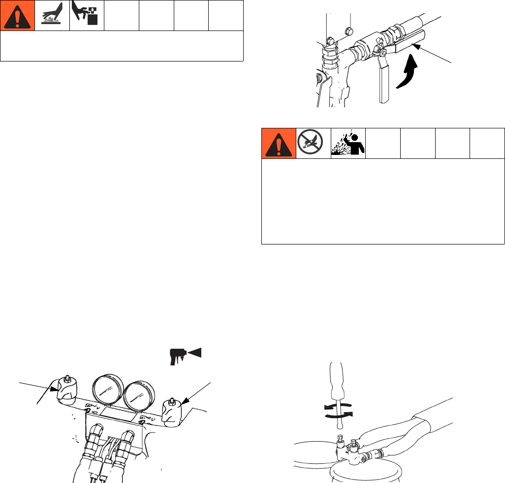
Startup
313997W 47
Startup
1. Use feed pumps to load fluid
NOTE:
The HFR is tested with oil at the factory. Flush out the oil
with a compatible solvent before dispensing. See Flush-
ing on page 52.
a. Check that all machine connections are setup.
See Setup procedure, page 38.
b. Check that inlet screens are clean before daily
startup, see page 56.
c. Check level and condition of ISO lube daily, see
IsoGuard Select® System on page 57.
d. Turn on component B (Blue) and component A
(Red) agitators, if used.
e. Turn both PRESSURE RELIEF/DISPENSE
valves (SA, SB) to DISPENSE .
f. Start feed pumps.
g. Open fluid inlet valves (FV). Check for leaks.
h. Use feed pumps to load system.
i. For models with an EP, Fusion, or P2 gun
only, hold gun fluid manifold over two grounded
waste containers. Open gun fluid valves A (Red)
and B (Blue) until clean, air-free fluid comes
from valves. Close valves.
j. For models with an MD2 Valve only, hold
MD2 valve nose piece, without a mixer installed,
over two grounded waste containers. Leave
mixer off and trigger gun until both fluids flow
freely from the nose piece without any air.
k. To prime the pump, cycle the pump a few times
or until air-free fluid dispenses.
Do not operate HFR without all covers and shrouds in
place.
ti9877a1
SA SB
Keep Components A (Red) and B (Blue) Separate
Cross-contamination can result in cured material in
fluid lines which could cause serious injury or damage
equipment. To prevent cross-contamination of the
equipment’s wetted parts, never interchange compo-
nent A (Red) and component B (Blue) parts.
FV
ti10002a1
ti2484a1
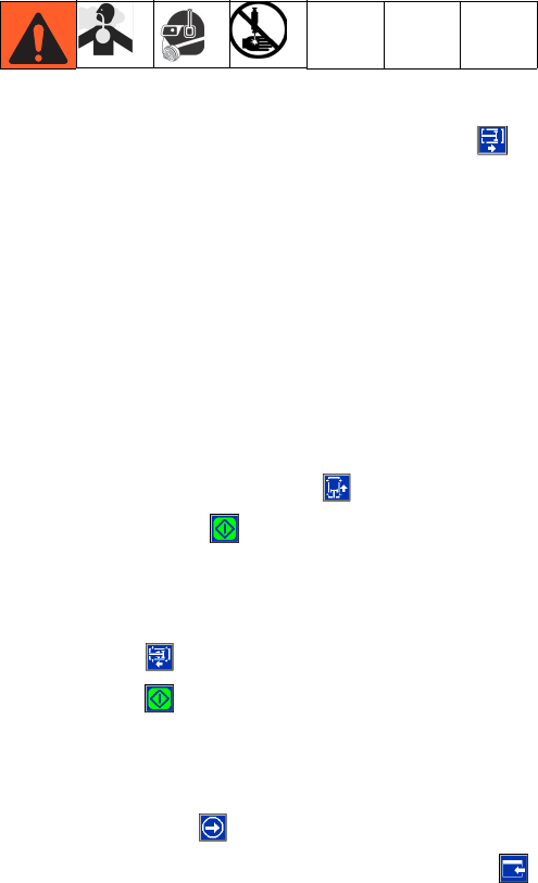
Startup
48 313997W
2. Calibrate HFR
The HFR calibration procedure is a two step process.
The first step, Learn Mode, must be performed when-
ever the pump line is rebuilt or if any other maintenance
is performed that may affect the mechanical tolerances
in the pump line. If the machine does not appear to be
utilizing the full extent of the pump stroke, or if the
machine appears to be contacting the end of the
hydraulic cylinder, follow the Learn Mode procedure.
The Learn Mode procedure will teach the system the
mechanical limits of travel.
Learn Mode Procedure:
a. Navigate to the Calibration screen.
b. Press the Learn Mode Calibration button
and set the mode to run as the dispense appli-
cator that is installed on the system.
NOTE: For circulation systems, set the mode as either
EP or MD2 valves. These settings will not dispense
material.
c. Place a waste container below the dispense
valve. The next steps will cause the machine to
dispense material for all other settings.
d. Press the go right button and then the dis-
pense button . The pump will travel to the
right most extreme position.
e. After the pump stops moving, press the go left
button and then press the dispense
button . The pump will travel to the left most
extreme position.
f. After the pump stops moving, press the con-
tinue button to go on to the next step in the
calibration process or the page back button
to return to the main Calibration screen.
NOTE: During this process, the system learned the
mechanical limits of travel. If the pump did not reach
both the left and right extreme limits for any reason,
repeat the procedure.
If the system is to be used in a Time or Volume Dis-
pense Mode, system calibration is complete after the
Learn Mode procedure described above. However, if the
system is to be used in Weight Dispense mode and the
application requires that the dispense amount be accu-
rate and consistent then the weight calibration proce-
dure below must be followed.
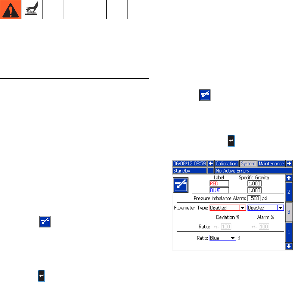
Startup
313997W 49
3. Set temperatures (Heated models only)
For detailed temperature adjustments, including alarm
levels, or upon initial machine configuration, see Condi-
tioning Screen 2 on page 78 for details. For minor
adjustments to the temperature setpoint once the
machine has been initially configured, see the Status
Screen on page 85.
4. Set system control and dispense modes: See
System Screen 1 on page 73.
5. Set pump sizes: See System Screen 1 on
page 73.
6. Define Shot Recipes
a. Navigate to the Shots screen.
b. Press to enter the screen.
c. Use the directional keypad to navigate to the
shot detail column for the desired shot number.
d. Type the desired setting for that item then
press .
e. Repeat the previous two steps for all desired
shot numbers.
7. Change pressure imbalance setting (optional)
The pressure imbalance function detects conditions that
can cause off-ratio dispense, such as loss of feed pres-
sure/supply, pump seal failure, clogged fluid inlet filter, or
a fluid leak.
The pressure imbalance default is factory-set at 500 psi
(3.5 MPa, 35 bar). For tighter ratio error detection, select
a lower value. For looser detection or to avoid nuisance
alarms, input a higher value.
a. Navigate to System Screen 3.
b. Press to enter the screen.
c. Navigate to the pressure imbalance field.
d. Type the desired pressure imbalance setting
then press Enter .
This equipment is used with heated fluid, which can
cause equipment surfaces to become very hot. To
avoid severe burns:
• Do not touch hot fluid or equipment.
• Allow equipment to cool completely before touch-
ing it.
• Wear gloves if fluid temperature exceeds 110°F
(43°C).
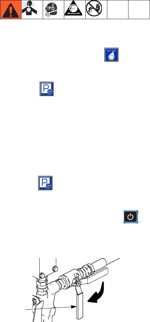
Shutdown
50 313997W
Shutdown
1. Park pumps.
a. From the Home screen, press and select
Standby mode.
b. Press . Material will dispense for non cir-
culation systems. Pump will park automatically.
Once pump is parked, pump will stop moving.
If a dispense gun with a trigger is installed,
pulling the trigger will begin a park operation.
Material will dispense for non circulation sys-
tems.
c. For models with an EP, Fusion, or P2 gun
only, turn diversion valves to tank then press
Park . Pressure must be below 400 psi
(2.8 MPa, 28 bar).
2. Press the enable/disable key on the ADM to
disable the ADM.
3. Turn main power switch (MP) to OFF position.
4. Close A (Red) and B (Blue) fluid supply valves (FV).
5. Perform Pressure Relief Procedure on page 51.
6. Shut down feed pumps as required. See feed pump
manual.
ti9883a1
FV
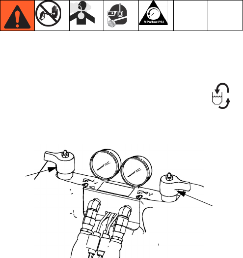
Pressure Relief Procedure
313997W 51
Pressure Relief Procedure
1. Shut off feed pumps and agitator, if used.
2. Turn PRESSURE RELIEF/DISPENSE valves (SA,
SB) to PRESSURE RELIEF/CIRCULATION .
Route fluid to waste containers or supply tanks.
Ensure gauges drop to 0.
3. For models with an dispense valve with a safety
lock, engage gun safety lock.
4. Relieve pressure in dispense valve. See dispense
valve manual.
ti9879a1
SA
SB
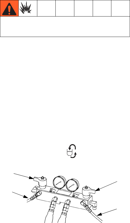
Flushing
52 313997W
Flushing
• Flush out old fluid with new fluid, or flush out old
fluid with a compatible solvent before introducing
new fluid.
• Use the lowest possible pressure when flushing.
• All fluid components are compatible with common
solvents. Use only moisture-free solvents. See
Technical Data on page 108 for list of wetted com-
ponents to verify compatibility of solvent with wetted
materials. See solvent manufacturers information for
material compatibility.
• To flush feed hoses, pumps, and heaters separately
from heated hoses, set PRESSURE RELIEF/DIS-
PENSE valves (SA, SB) to PRESSURE
RELIEF/CIRCULATION . Flush through bleed
lines (N).
• To flush entire system, circulate through gun fluid
manifold (with manifold removed from gun).
• To prevent moisture from reacting with isocyanate,
always leave the system dry or filled with a mois-
ture-free plasticizer or oil. Do not use water. See
Important Two-Component Material Information
on page 20.
•Solvent pails used when flushing: follow your local
code. Use only metal pails, which are conductive,
placed on a grounded surface. Do not place pail on
a nonconductive surface, such as paper or card-
board, which interrupts grounding continuity.
•To maintain grounding continuity when flushing or
relieving pressure, hold a metal part of dispense
gun firmly to the side of a grounded metal pail, then
trigger gun.
Flush equipment only in a well-ventilated area. Do not
dispense flammable fluids. Do not turn on heaters
while flushing with flammable solvents.
SA
SB
ti9880a1
N
N
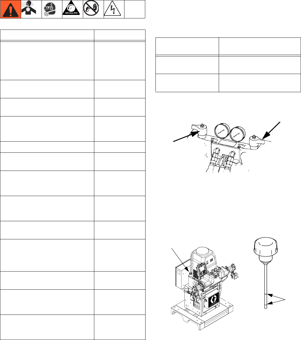
Maintenance
313997W 53
Maintenance
Change Break-in Oil
After initial break-in, see Table 5 for recommended fre-
quency of oil changes.
Table 2: Frequency of Oil Changes
Grease Circulation Valves With Fusion
Grease (117773)
Check Hydraulic Fluid Level
Check hydraulic fluid level on dipstick (DS). Fluid level
must be between indent marks (IM) on dipstick. Refill as
required with approved hydraulic fluid; see Technical
Data on page 108. If fluid is dark in color, change fluid
and filter.
Task Schedule
Change break-in oil in a new unit After first 250
hours of opera-
tion or within 3
months, which-
ever comes first
Inspect hydraulic and fluid lines
for leaks
Daily
Inspect fluid inlet strainer
screens, page 56
Daily
Inspect IsoGuard Select fluid
level and condition, refill or
replace as needed, page 57
Daily
Check hydraulic fluid level Weekly
Grease circulation valves with
Fusion grease (117773)
Weekly
Verify operation of air drying sys-
tem to prevent isocyanate crystal-
lization
Weekly
Verify vent holes on bottom of
electrical cabinet are clear and
unobstructed
Weekly
Inspect air filter (part 24H018),
clean or replace as necessary,
Daily
Use compressed air to remove
dust buildup on control boards,
fan, motor (under shield), and
hydraulic oil coolers
Monthly
Clean up all hydraulic leaks; iden-
tify and repair cause of leak
As needed
Clean dispense valve mix cham-
ber ports regularly, see dispense
valve manual
See dispense
valve manual
Clean dispense valve check valve
screens, see dispense valve
manual
See dispense
valve manual
Ambient
Temperature
Recommended
Frequency
0 to 90°F
(-17 to 32°C)
1000 hours or 12 months,
whichever comes first
90°F and above
(32°C and above)
500 hours or 6 months,
whichever comes first
ti9879a1
S
DS
ti7861a1
IM
24C352_313998_1
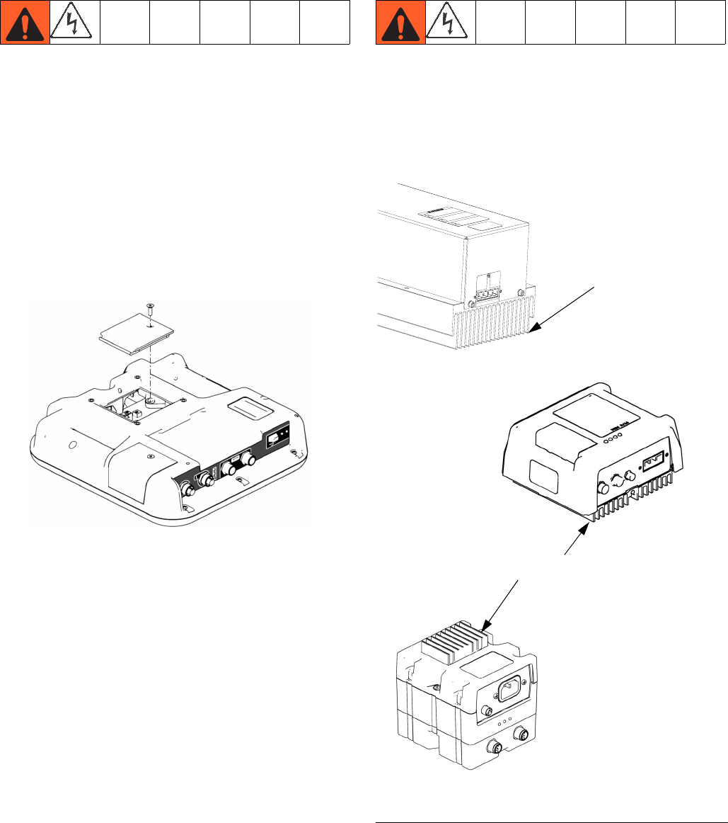
Maintenance
54 313997W
ADM - Battery Replacement and
Screen Cleaning
Battery Replacement
A lithium battery maintains the ADM clock when power
is not connected.
To replace the battery:
1. Disconnect power to the ADM.
NOTE: This can be done by removing the CAN cable
from the bottom of the ADM.
2. Remove rear access panel.
3. Remove the old battery and replace with a new
CR2032 battery.
4. Properly dispose the old lithium battery according to
local codes.
5. Replace rear access panel.
6. Connect the power to the ADM and reset the clock
through Advanced Screen 1. Refer to Appendix B
- ADM Setup Screens Overview for more detail.
Cleaning
Use any alcohol-based household cleaner, such as
glass cleaner, to clean the ADM. Spray on the rag then
wipe ADM. Do not directly spray the ADM.
MCM and TCM - Clean Heat Sink
Fins
Keep heat sink fins clean at all times. Clean them using
compressed air.
NOTE: Do not use conductive cleaning solvents on the
module.
ti12364a1
FIG. 14: Clean Heat Sink Fins
r_257396_3b9905_02b
Heat
Sink Fins
ti12353a1
ti12357a1
Heat Sink Fins
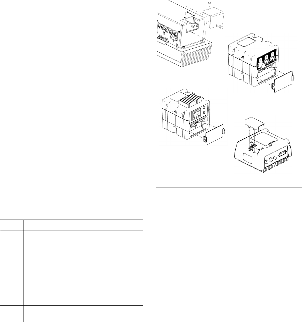
Maintenance
313997W 55
Install Upgrade Tokens
NOTE: The Motor Control Module, Fluid Control Mod-
ule, and Temperature Control Module connection to the
system is temporarily disabled during the installation of
upgrade tokens.
To install software upgrades:
1. Use correct software token stated in the table. See
Graco Control Architecture™ Module Programming
manual for instructions.
NOTE: Upgrade all modules in the system to the
software version on the token, even if you are
replacing only one or two modules. Different soft-
ware versions may not be compatible.
All data in the module (System Settings, USB Logs,
Recipes, Maintenance Counters) may be reset to
factory default settings. Download all settings and
user preferences to a USB before the upgrade, for
ease of restoring them following the upgrade.
See manuals for locations of specific GCA compo-
nents.
The software version history for each system can be
viewed in the technical support section at
www.graco.com.
Token Application
16H821 HFR:
- Advanced Display Module
- Motor Control Module
- High Power Temperature Control Module
- Fluid Control Module (AC Power Pack)
- Discrete Gateway Module
- Communication Gateway Module
16G584 Tank Stand:
- Fluid Control Module
- Low Power Temperature Control Module
16G407 Ratio Monitoring (Flow Meters):
- Fluid Control Module
FIG. 15: Remove Access Cover
r
_257396_3b9905_04b
ti12334a1
ti12358a1
ti12354a1
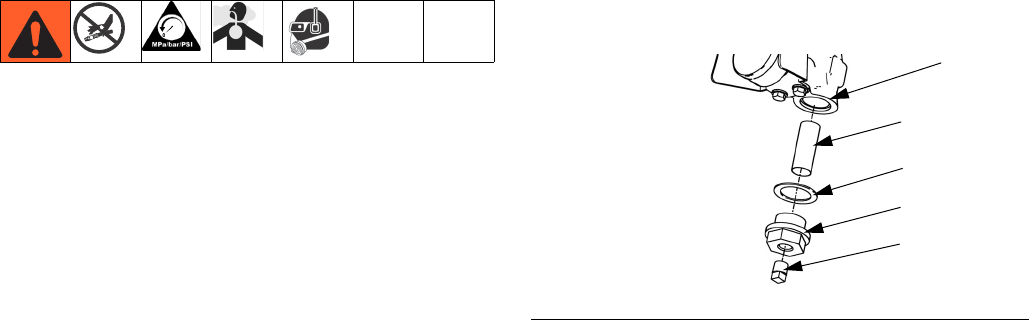
Maintenance
56 313997W
Fluid Inlet Strainer Screen
The inlet strainers filter out particles that can plug the
pump inlet check valves. Inspect the screens daily as
part of the startup routine, and clean as required. The
standard strainer is 20 mesh.
Use clean chemicals and follow proper storage, transfer,
and operating procedures, to minimize contamination of
the A-side screen.
NOTE:
Clean the A-side screen only during daily startup. This
minimizes moisture contamination by immediately flush-
ing out any isocyanate residue at the start of dispensing
operations.
1. Perform Pressure Relief Procedure on page 51.
2. Close the fluid inlet valve at the pump inlet and shut
off the appropriate feed pump. This prevents mate-
rial from being pumped while cleaning the screen.
3. Place a container under the strainer manifold (59d)
to catch fluid. Remove the strainer plug (59j).
4. Remove the screen (59g) from the strainer manifold.
Thoroughly flush the screen with compatible solvent
and shake it dry. Inspect the screen. If more than
25% of the mesh is blocked, replace the screen.
Inspect the gasket (59h) and replace as required.
5. Ensure the pipe plug (59k) is screwed into the
strainer plug (59j). Install the strainer plug with the
screen (59g) and gasket (59h) in place and tighten.
Do not overtighten. Let the gasket make the seal.
6. Open the fluid inlet valve, ensure that there are no
leaks, and wipe the equipment clean. Proceed with
operation.
FIG. 16. Fluid Inlet Strainer
59g*
59h
59j
59k
ti9886a1
59d
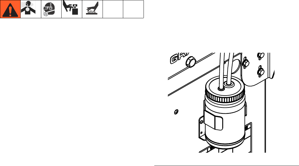
Maintenance
313997W 57
IsoGuard Select® System
Check the condition of the A (Red) pump IsoGuard
Select fluid daily. Change the fluid if it becomes a gel, its
color darkens, or it becomes diluted with isocyanate.
Gel formation is due to moisture absorption by the pump
IsoGuard Select fluid (24F516). The interval between
changes depends on the environment in which the
equipment is operating. The pump lubrication system
minimizes exposure to moisture, but some contamina-
tion is still possible.
Fluid discoloration is due to continual seepage of small
amounts of isocyanate past the pump packings during
operation. If the packings are operating properly, Iso-
Guard Select fluid (24F516) replacement due to discol-
oration should not be necessary more often than every 3
or 4 weeks.
To change pump IsoGuard Select fluid (24F516):
1. Perform Pressure Relief Procedure on page 51.
2. Remove fittings from IsoGuard Select fluid cylinder
inlet and outlet ports. Keep supply tube (ST), return
tube (RT), and leak management tube (LT) con-
nected to the fittings.
3. Carefully place ends of tubes with fittings still con-
nected into an empty pail to drain IsoGuard Select
fluid.
4. Lift the IsoGuard Select fluid reservoir (LR) out of
the bracket (RB) and remove the container from the
cap. Holding the cap over a suitable container,
remove the inlet check valve and allow the IsoGuard
Select fluid to drain. Reattach the check valve to the
inlet hose. See FIG. 17.
5. Drain the reservoir and flush it with clean IsoGuard
Select fluid (24F516).
6. When the reservoir is flushed clean, fill with fresh
IsoGuard Select fluid (24F516).
7. Thread the reservoir onto the cap assembly and
place it in the bracket (RB).
8. Push the supply tube (ST) approximately 1/3 of the
way into the reservoir.
9. Push the return tube (RT) into the reservoir until it
reaches the bottom.
NOTE:
The return tube must reach the bottom of the reservoir,
to ensure that isocyanate crystals will settle to the bot-
tom and not be siphoned into the supply tube and
returned to the pump.
Prime IsoGuard Select Fluid Cylinder
Ensure that the IsoGuard Select fluid cylinder outlet
faces upward for air to exhaust.
1. Install IsoGuard Select fluid cylinder inlet fitting and
inlet tube into bottom of cylinder. The inlet tube is
the tube with a check valve installed in it which
points in the direction of flow towards the IsoGuard
Select fluid cylinder.
2. Install IsoGuard Select fluid cylinder outlet fitting
and outlet tube into top of cylinder. The outlet tube is
the tube with a check valve installed in it which
points in the direction of flow away from the Iso-
Guard Select fluid cylinder.
3. Remove check valve from end of outlet tube.
4. Use funnel to pour IsoGuard Select fluid (24F516)
into tube to fill cylinder.
5. With check valve arrow pointing away from the Iso-
Guard Select fluid cylinder, install check valve in end
of outlet tube.
6. Install tubes into reservoir and install reservoir into
holder.
FIG. 17: IsoGuard Select Fluid System
24C352_313998_8e
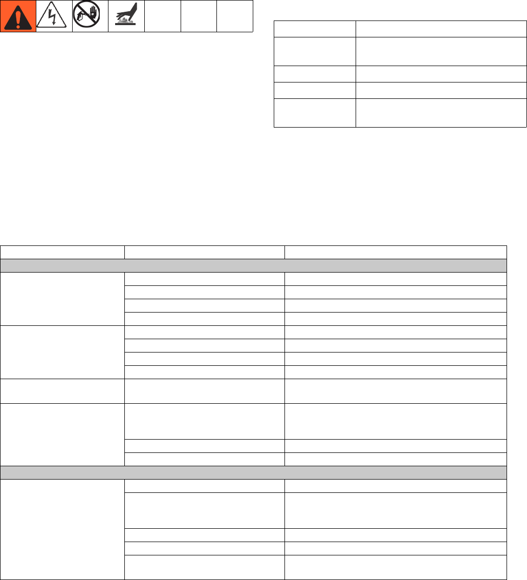
Troubleshooting
58 313997W
Troubleshooting
Before performing any troubleshooting procedure:
1. Perform Pressure Relief Procedure on page 51.
2. Turn main power OFF.
3. Allow equipment to cool.
Try the recommended solutions in the order given for
each problem, to avoid unnecessary repairs. Also,
determine that all circuit breakers, switches, and con-
trols are properly set and wiring is correct before assum-
ing there is a problem.
Light Tower (Optional)
Errors include advisories, deviations, or alarms, so
green will only be on when none of these occur. A yellow
light can be on at the same time as red (flashing or solid
on) when an advisory exists at the same time as a devi-
ation or alarm.
Common Problems
Signal Description
Green on only System is powered up and there are
no error conditions present
Yellow on An advisory exists
Red flashing A deviation exists
Red on The system is shut down due to an
alarm occurring.
Problem Cause Solution
General
Display Module completely
dark
No Power Verify AC Power switch is ON
Thrown Breaker Check Machines Breakers and Reset
Loose Connection Tighten 5-pin cable on Advanced Display Module
Bad Display Module Replace Advanced Display Module
No or incorrect amount of
material dispensed from
either side
Ball Valve closed (if Installed) Open tank ball valve.
Tank Empty Add fluid
Tank Clogged Clean tank
Air In Material Prime the machine
Significant material leaking
from pump seal
Pump shaft worn and/or shaft seal
worn
Remove pump shaft assembly and reinstall read
pump rebuild kit
Material dispensed not cor-
rect weight
Specific gravity of one or more of the
two materials has changed since cali-
bration
Run calibration
Check valve malfunction Remove check valve; clean or replace as necessary
Piston worn or broken Replace Piston
A (Red) and B (Blue) Primary Heaters
Control of primary heat is
abnormal; high temperature
overshoots
Dirty RTD connection Unplug and re-plug RTD wires.
RTD not contacting heater element Loosen ferrule nut, push in RTD so tip contact heater
element. Holding RTD tip against heater element,
tighten ferrule nut 1/4 turn past tight.
Failed heater element Replace
Signal failure from RTD Check connections
RTD wired incorrectly Check connections. Power up zones one at a time
and verify that temperature for each zone rises.

Troubleshooting
313997W 59
Hose Heat System
Hose heats but heats slower
than usual or it does not
reach temperature
Ambient temperature is too cold Use auxiliary hose system.
FTS failed or not installed correctly Check FTS
Low supply voltage Verify line voltage. Low line voltage significantly
reduces power available to hose heat system, affect-
ing longer hose lengths.
Hose does not maintain tem-
perature while spraying
A and B setpoints too low Increase A (Red) and B (Blue) setpoints. Hose is
designed to maintain temperature, not to increase it.
Ambient temperature is too cold Increase A (Red) and B (Blue) setpoints to increase
fluid temperature and keep it steady
Flow too high Use smaller mix chamber. Decrease pressure.
Hose was not fully preheated Wait for hose to heat to correct temperature before
spraying
Low supply voltage Verify line voltage. Low line voltage significantly
reduces power available to hose heat system, affect-
ing longer hose lengths.
Hose temperature exceeds
setpoint
A (Red) and/or B (Blue) primary heat-
ers are overheating material
Check primary heaters for either an RTD problem or a
failed element attached to thermocouple
Faulty RTD connections Verify that all FTS connections are snug and that pins
of connectors are snug and that pins of connects are
clean. Examine connection of thermocouples to long
green plug on heater control board. Unplug and
re-plug RTD wires, cleaning off any debris. Unplug
and re-plug long green connector on heater control
board.
Erratic hose temperature Faulty RTD connection Verify that all FTS connections are snug and that pins
of connectors are clean. Examine connection of RTD
to long green plug on heater control board. Unplug
and re-plug RTD wires, cleaning off any debris.
Unplug and re-plug long green connector.
FTS not installed correctly FTS should be installed close to end of hose in same
environment as gun. Verify FTS installation.
Hose does not heat FTS failed or is not contacting cor-
rectly
Check FTS
FTS not installed correctly FTS should be installed close to end of hose in same
environment as gun. Verify FTS installation.
Temperature control alarm See Appendix D - ADM Error Codes on page 88
Hoses near system are
warm, but hoses down-
stream are cold
Shorted connection or failed hose
heating element
With hose heat on and temperature setpoint above
displayed hose zone temperature, verify voltage
between connectors at each section of hose.
Voltage should drop incrementally for each section of
hose further from the system. Use safety precautions
when hose heat is turned on.
Proportioning System
Proportioning pump does not
hold pressure when stalled
Pump piston or intake valve leaking 1. Observe gauges to determine which pump is los-
ing pressure.
2. Determine in which direction the pump has
stalled by observing which directional valve indi-
cator light is on.
3. Repair the valve.
Problem Cause Solution

Troubleshooting
60 313997W
Material imbalance. Inadequate flow from pump; cavitation Increase fluid supply to proportioning pump:
•Use 2:1 supply pump
•Use minimum 3/4 in. (19 mm) ID supply hose, as
short as practical
Fluid is too thick. Consult your material supplier for
the recommended fluid temperature to maintain a vis-
cosity of 250 to 1500 centipoise.
Clean inlet strainer screen
Worn pump inlet valve ball/seat or gasket
Pressure relief/circulation valve leak-
ing back to supply
Remove return line and determine if flow is present
while in SPRAY mode
Erratic pump movement Pump cavitation Feed pump pressure is too low. Adjust pressure to
maintain 100 psi (0.7 MPa, 7 bar) minimum.
Pump output low Obstructed fluid hose or gun; fluid
hose ID too small
Open, clear; use hose with larger ID
Worn piston valve or intake valve in
displacement pump
See pump manual
Inadequate feed pump pressure Check feed pump pressure and adjust to 100 psi (0.7
MPa, 7 bar) minimum.
Problem Cause Solution
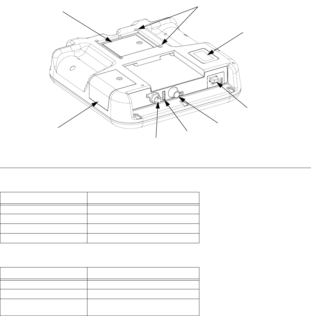
Troubleshooting
313997W 61
ADM Troubleshooting
ADM Module Status LEDs (CN) Conditions
USB Module Status LEDs (CL) Conditions
FIG. 18: ADM Component Identification - Rear
CR
CK
CJ
CL
CP
CN
CM
CS
r_24E451_3B9900_1a
Module Status LED Signal Description
Green on System is powered up.
Yellow on Communication in progress.
Red solid ADM hardware failure.
Red flashing Uploading software.
Module Status LED Signal Description
Green flashing System is powered up.
Yellow on Downloading information to USB
Green/Yellow Flashing ADM is busy, USB cannot transfer
information when in this mode
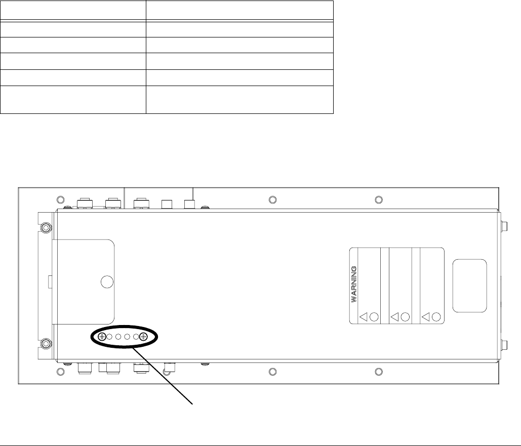
Troubleshooting
62 313997W
Motor Control Module
For MCM location, see reference MA in FIG. 2 on
page 25.
Diagnostic Information
7Table 3: LED Status Signal
Module Status LED Signal Description
Green on System is powered up.
Yellow on Internal communication in progress.
Red solid MCM hardware failure. Replace MCM.
Red flashing fast Uploading software.
Red flashing slow Token error. Remove token and upload
software token again.
FIG. 19: LED Signals
LED
Signals r_257396_3b9905_07b
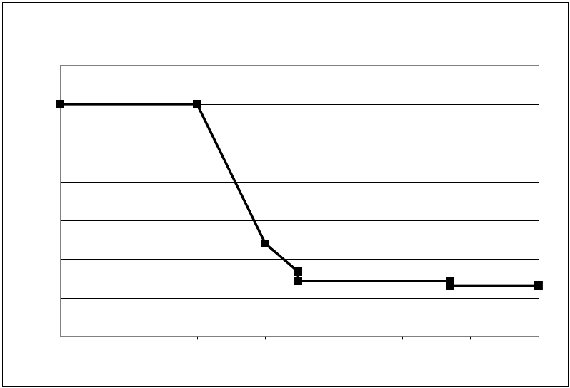
Troubleshooting
313997W 63
Acceptable Size and Duration of Power Line Voltage Fluctuations
The Motor Control Module is designed to withstand volt-
age fluctuations from the incoming power supply. If the
incoming power supply goes outside of the tolerable
range, an over-voltage condition is flagged and the sys-
tem shuts down in an alarm state. Excessive or
repeated over-voltage may permanently damage hard-
ware. The chart below shows the permissible magnitude
and duration of temporary over-voltage events. Consult
a qualified electrician if there are any concerns about
the available power supply.
Maximum Permissible Transient Voltage Surges
* Constructed from ITIC 1996 curve, referenced by IEC 61000-2-4
1200Vac, 1697Vdc
264Vac, 373Vdc
336Vac, 475Vdc
288Vac, 407Vdc
480Vac, 679Vdc
<--1 MW Max Surge Power
<--150 KW Max Surge Power
<--50 KW Max Surge Power <--No Power Limit
0
200
400
600
800
1000
1200
1400
Time (seconds)
Voltage (Volts RMS)
0.000001 0.00001 0.0001 0.001 0.01 0.1 1 10
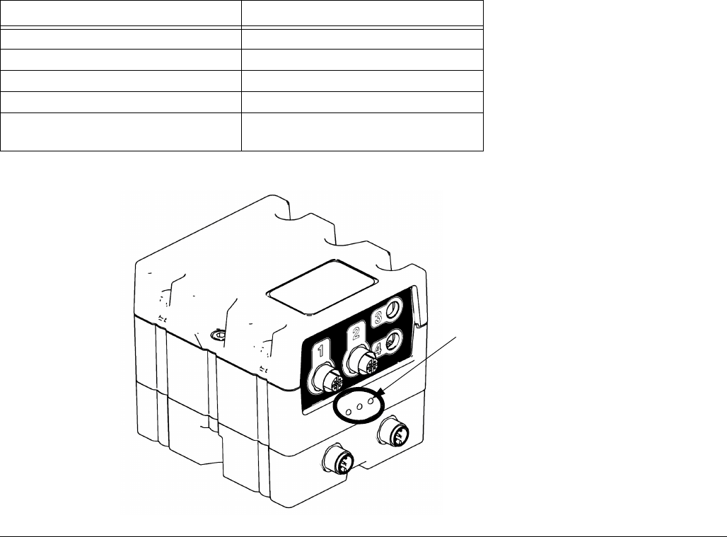
Troubleshooting
64 313997W
Fluid Control Module
Diagnostic Information
Module Status LED Signal Diagnosis
Green on System is powered up
Yellow Internal communication in progress
Red solid FCM hardware failure. Replace FCM.
Red flashing fast Uploading software
Red flashing slow Token error. Remove token and
upload software token again.
FIG. 20:
ti12337a1
Module Status LEDs
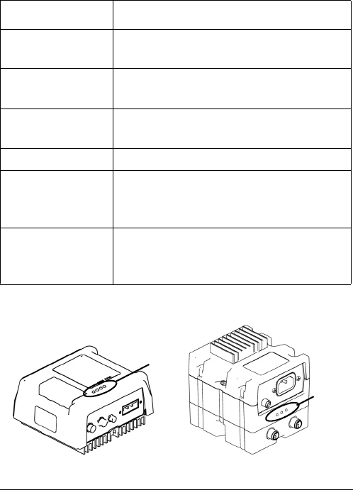
Troubleshooting
313997W 65
Temperature Control Module
Diagnostic Information
Module Status LEDs
Signal Description
Green on Temperature control module is
powered up.
Yellow on Internal communication in prog-
ress.
Red solid Temperature control module failure.
See Troubleshooting table.
Red flashing Software is updating.
Blue light off
(High Power
Module only)
Temperature control module is off.
See Troubleshooting table.
Blue flashing
(High Power
Module only)
Length of flashes indicates amount
of power running through tempera-
ture control module.
FIG. 21: LED Signals
LED
Signals
ti12353a1 ti12357a1
LED
Signals
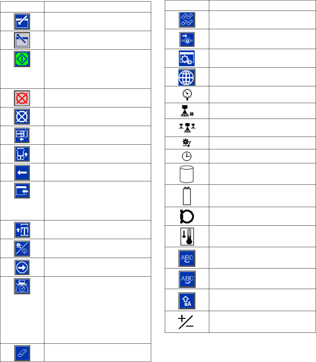
Appendix A - ADM Icons Overview
66 313997W
Appendix A - ADM Icons Overview
Setup Screen Icons
Icon Description
Enter Screen
Exit Screen
On Learn Mode Calibration screen:
Move pump
All other screens:
Begin Dispense
Stop Dispense
Abort Changing the Label
Select left direction
Select right direction
Backspace
Back to main calibration screen from
learn mode calibration screen
or
Back to system screen 2 from mix
head operating details screen
Access Learn Mode Calibration
screen
Run MCM Learn Mode
Proceed to next step in calibration
procedure
On Main Calibration screen:
Calibrate Weight Dispense or Enter
Specific Gravity Information
On Flow Meter Calibration screen:
Use Dispensed Material Weight to
Calibrate Flow Meters. If pressed,
icon will change and units are
changed to volume units.
Erase Selected Item or Control Data
Erase All Counters on Page
Access Flowmeter Calibration
Valve Details
Selects all shots to be changed to the
same user specific value
Pressure
Shot Number
Sequence Position
Flow
Time (Duration)
Tank Blanket Heater
Primary Heater
Heated Hose
Chiller
Move Cursor to the Left
Move Cursor to the Right
Upper/Lower Case Letters
Positive / Negative
Icon Description
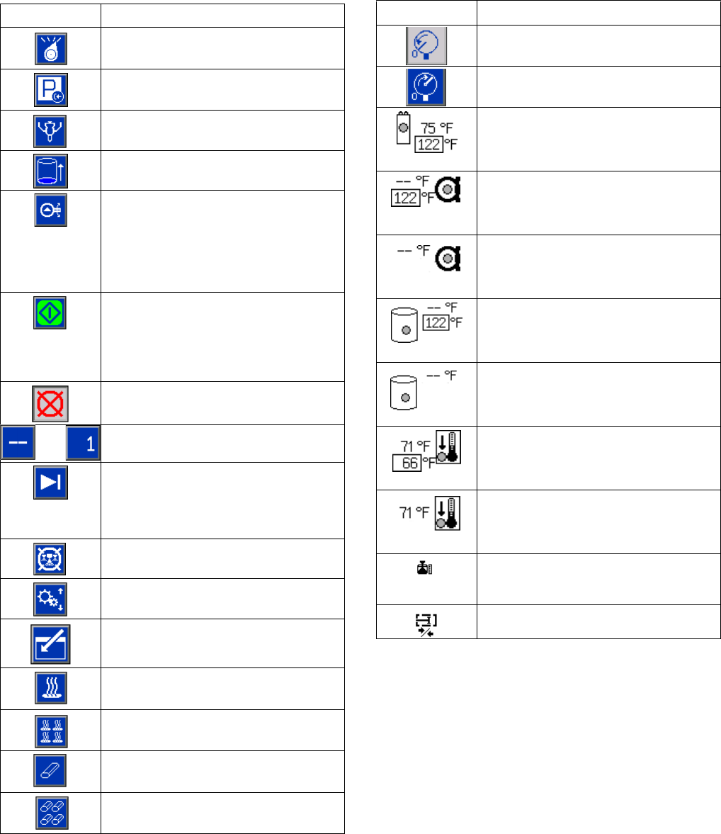
Appendix A - ADM Icons Overview
313997W 67
Run Screen Icons
Icon Description
Select mode.
Set system in park (icon will be
selected when system is parked)
Open, Close Valve
A (Red) and B (Blue) refill button
(Press to start/abort refill)
With a mix head installed: Turns on
the mix head hydraulics and puts the
machine in low pressure circulation.
Press a second time to turn off insti-
gated system action.
If Green:
Allowed to Dispense
If Red:
Not Allowed to Dispense
Stop Dispense
OR Jump in and use the key pad to select
a shot number.
Skip the next shot in selected
sequence. Only available when the
system is not dispensing.
Abort sequence and reset to first valid
position
Edit Operator Dispense Setting
Press to enter the Conditioning Con-
trol screen
Turn on or off the highlighted zone.
Turn on or off all zones.
Erase a single batch
Erase all batch data points
Sets machine to low pressure
Sets machine to high pressure
Current and setpoint temperature for
primary heater. Not displayed if heat
zone is not enabled.
Current and setpoint temperatures for
heated hose. Not displayed if heat
zone is not enabled.
Current temperatures for heated hose
monitor. Not displayed if heat zone is
not enabled.
Current and setpoint temperatures for
tank blanket. Not displayed if heat
zone is not enabled.
Current temperatures for tank blanket
monitor. Not displayed if heat zone is
not enabled.
Current and setpoint temperatures for
chiller. Not displayed if heat zone is
not enabled.
Current temperatures for chiller moni-
tor. Not displayed if heat zone is not
enabled.
Amount of material moved through
pump (volume tracking)
Cycles
Icon Description
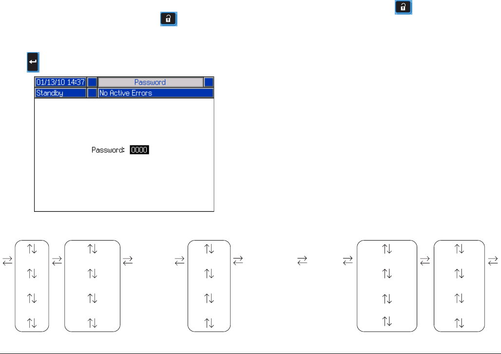
Appendix B - ADM Setup Screens Overview
68 313997W
Appendix B - ADM Setup Screens Overview
The ADM will start in the Run screens at the “Home”
screen. From the Run screens, press to access the
Setup screens. If the Setup screens password is turned
on, use the ADM keypad to enter the password then
press .
From the Setup screens, press to access the Run
screens. For Run screens information, see Appendix C
- ADM Run Screens Overview on page 82. FIG. 22
shows the flow of the Setup screens.
FIG. 22: Setup Screens Navigation Diagram
Calibration Maintenance
Shot #1
Shot #2
Shot #...
Sequences #1
Sequences #2
Sequences #...
Advanced #1
Advanced #2
Advanced #...
System #1
System #2
System #3
Supply Conditioning #1
Conditioning #2
Conditioning #3
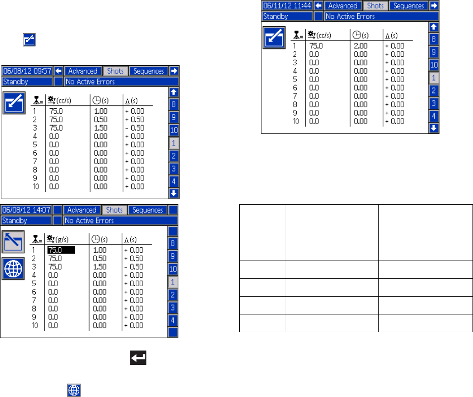
Appendix B - ADM Setup Screens Overview
313997W 69
Shots Screen
This screen allows the user to edit shot definitions. The
contents of this screen change based on the Dispense
and Control Mode selections. Shots may be defined by
pressure or flow rate depending upon the Control Mode
selection and by time (duration), volume, or weight
depending upon the Dispense Mode selection. See Sys-
tem Screen #1 for Control and Dispense Mode options.
See Home Screen, Shot Mode on page 83 for informa-
tion on how to use predefined shots.
NOTE: 100 shot definition are available across ten
pages.
To edit a shot definition:
1. Press then use the arrow keys to navigate to the
desired value.
2. Type the new value then press to accept the
new value.
3. If desired, press to quickly enter the same value
for the rate and time/volume/weight.
4. Repeat step 2 as required.
Due to variation in material properties, the Δ column
gives the ability to adjust the shot time/volume/weight for
each defined shot.
NOTE: If the Δ column is used, it is recommended that
a minimum of 5 shots are dispensed, measured and
averaged for each dispense before entering a value for
the Δ column.
Time Based Example:
A 75 cc/s shot is defined to dispense for 2 seconds.
1. Dispense 5 shots into 5 separate containers.
2. Measure the dispensed amount and record the
data.
3. Calculate the average of the 5 shots.
Example 1 = 146cc
Example 2 = 156cc
Shot
Example 1
Dispensed Volume
(cc)
Example 2
Dispensed Volume
(cc)
1 146.2 156.2
2146.4 156.4
3 145.6 155.6
4145.8 155.8
5 146.0 156.0
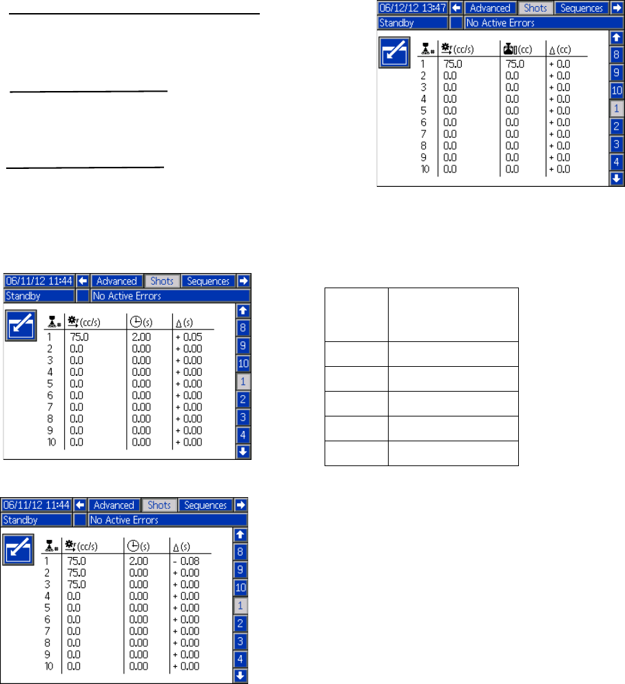
Appendix B - ADM Setup Screens Overview
70 313997W
4. Use the following formula to calculate the Δ column
value.
5. Enter the calculated value in the Δ column.
NOTE: Depending on the dispensed volume average,
the Δ column may be either a positive or negative value.
Volume/Weight Based Example:
A 75 cc/s shot is defined to dispense for 75 cc.
1. Dispense 5 shots into 5 separate containers.
2. Measure the dispensed amount and record the
data.
3. Calculate the average of the 5 shots.
Example 3 = 72.5cc
4. Use the following formula to calculate the Δ column
value.
((Flow Rate x Time) - Average Volume)
Flow Rate
Example 1:
= 0.053 sec
Example 2:
((75cc/sec x 2sec) - 146cc)
75 cc/sec
= -0.08 sec
((75cc/sec x 2sec) - 156cc)
75 cc/sec
Example 1:
Example 2:
Shot
Example 3
Dispensed Volume
(cc)
1 72.2
272.4
3 72.6
472.8
5 72.5
(Requested Amount - Actual Amount)
Example 3:
(75cc - 72.5cc = 2.5cc)
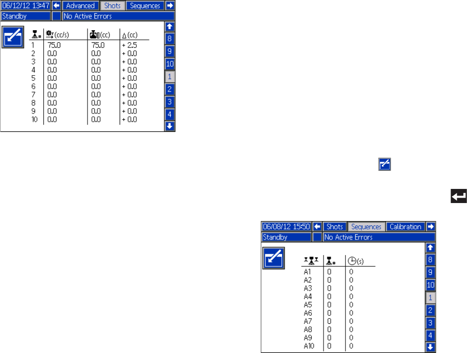
Appendix B - ADM Setup Screens Overview
313997W 71
5. Enter the calculated value in the Δ column. Sequences Screen
This screen allows the user to edit sequence informa-
tion. The contents of this screen change based on the
Dispense and Control Mode selections.
Dispense detail is shown as volume, time, or weight
depending on which Dispense Mode is selected. See
System Screen 1 on page 73 for Dispense Mode
options. See Home Screen, Sequence Mode on
page 84 for information on how to use predefined
sequences.
NOTE: Five sequences with 20 positions each are avail-
able across 10 pages.
To edit a sequence:
1. Press the Enter screen button then use the
arrow keys to navigate to the desired value.
2. Type the new value then press the Enter button
to accept the new value.
Example 3:
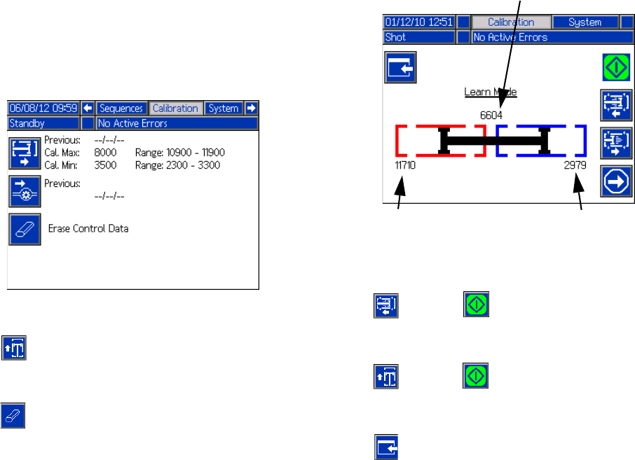
Appendix B - ADM Setup Screens Overview
72 313997W
Calibration Screen, Main
This screen shows calibration information for the system
and provides access to other calibration screens. See
Calibrate HFR on page 48 for how to use the calibration
screens to calibrate the machine.
The date next to each key represents the last time that
calibration was performed.
The “Cal. Min” and “Cal. Max” values are the system
recognized extreme ends of piston travel. See Calibra-
tion Screen, Learn Mode.
Press to go to the Calibration Screen, Learn
Mode screen.
Press to erase the motor control database in the
motor control module.
Calibration Screen, Learn Mode
This screen allows the user to calibrate piston position.
The piston can be moved to the left and right to obtain
the full range of motion. See Calibrate HFR on page 48
for how to use this screen to calibrate the machine.
Press and then to move the pump all the way
to the left.
Press and then to move the pump all the way
to the right.
Press to return to the Calibration Screen, Main.
This saves the new left and right numbers.
Previously saved left
position
Previously saved right
position
Current position
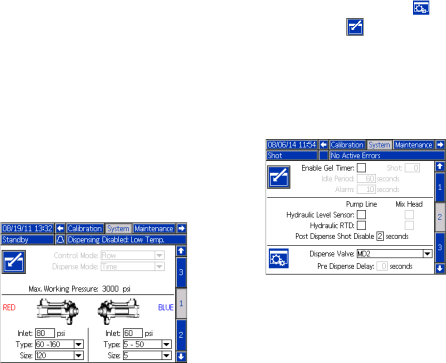
Appendix B - ADM Setup Screens Overview
313997W 73
System Screen 1
NOTE: Not all of the following modes may be available
depending on the dispense valve selected.
This screen allows the user to set important system set-
tings specific to what dispense applicator has been
selected. Control Mode can be set to Pressure or Flow.
With Control Mode set to Pressure, the machine will
adjust dispense flow rate in order to maintain the
requested pressure. With Control Mode set to Flow, the
machine will dispense at a continuous flow rate regard-
less of pressure fluctuations unless pressure alarm con-
ditions occur.
Dispense Mode can be set to Time, Volume, or Weight.
Dispense Mode controls how displayed amounts are
measured. If Dispense Mode is set to Weight, then the
machine dispenses until the desired weight of material
is dispensed. See Calibrate HFR on page 48 for more
information.
Pump sizes and inlet pressures must be entered on this
screen.
If pump sizes and inlet pressures are not entered prop-
erly, system performance will be affected. The inlet pres-
sure must be set to the maximum feed pressure that will
be seen by that side of the machine.
The maximum working pressure for the machine is dis-
played on this screen. The maximum working pressure
is dependent on the installed hoses and dispense valve.
The maximum working pressure is set to the lowest
rated system component. If 2000 psi hoses are installed
and the maximum working pressure displayed is not
2000 psi, see HFR repair/parts manual for instructions
to set the maximum working pressure for hoses. If the
installed dispense valve rating is below the maximum
working pressure shown here, verify the correct dis-
pense valve is selected on System Screen 2.
System Screen 2
This screen allows the user to set the Gel Timer proper-
ties and set which items are installed on the machine.
When enabling the Gel Timer, the user must select one
of the 100 available shot definitions to use as the Gel
Shot. This shot will be dispensed when the Idle Period
expires. The Idle Period will begin after a dispense is
completed. Any dispense operation in the middle of the
timer countdown will reset the Idle Period counter. The
system will generate an audible alarm based upon the
user Alarm setting. The alarm will sound the
user-entered number of seconds before the Idle Period
expires.
The hydraulic level sensor and hydraulic RTD for both
the pump line and mix head must be marked as enabled
when installed in the system. If the sensors are not
marked as enabled, they will be ignored by the machine
controls.
Select the dispense valve installed in the system. This
selection is critical to ensure proper operation of the
machine. When a mix head is selected, button will
become active when the is pressed. When active,
pressing this button will open a screen used to define
the mix head operating parameters. See the Mix Head
Operating Details Screen on page 74.
Selecting the dispense valve will limit the system maxi-
mum working pressure to the maximum working pres-
sure of the dispense valve. See System Screen 1 on
page 73.
Post Dispense Shot Disable is a feature where the user
can disable shot requests for zero to five seconds after
the completion of a dispense. This feature is not applica-
ble for P2/Fusion Dispense Valves. This feature can not
be active if the Pre Dispense Delay feature is active.
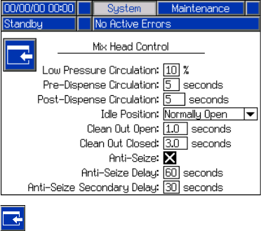
Appendix B - ADM Setup Screens Overview
74 313997W
Pre Dispense Delay is a feature where the HFR can
delay the start of a dispense until the user has pressed
and held the foot switch for the duration entered. For
example, if the user enters a five second duration, the
footswitch must be held on continuously for five seconds
before the HFR will start a dispense. This feature is not
available for recirculation systems or applicable for
P2/Fusion Dispense Valve applications. This feature can
not be active if the Post Dispense Shot Disable feature
is active.
Mix Head Operating Details Screen
This screen allows the user to define the mix head oper-
ating parameters.
•Low Pressure Circulation: The percentage of set-
point at which the system will run during low pres-
sure circulation.
•Pre-Dispense Circulation: The time for which the
system will circulate at high pressure prior to dis-
pensing when the dispense command is triggered
while the system is in low pressure circulation.
•Post-Dispense Circulation: The time duration that
the system will remain in high pressure circulation
after a dispense before dropping into low pressure
circulation.
•Idle Position: Applies to an L-Head only. The posi-
tion of the clean out rod when the mix head is idle.
•Clean Out Open: Applies to an L-Head only. The
amount of time the clean out rod will remain open
immediately after the completion of a dispense.
•Clean Out Closed: Applies to an L-Head in a Nor-
mally Open configuration only. The amount of time
the clean out rod will remain closed when it closes
after the completion of a dispense (after the clean
out open time delay).
•Anti-Seize Delay: Applies to an L-Head in a Nor-
mally Closed configuration only. After a shot occurs
and the cleanout piston closes, the first anti-seize
delay will count down then the cleanout piston will
open and close to break loose from any curing
material. The second anti-seize timer will then begin
counting down and the cleanout piston will open and
close again to break loose from any remaining cur-
ing material. If a shot occurs before both anti-seize
timers elapse, the anti-seize timers restart.
Press to go back to the System Screen 2.

Appendix B - ADM Setup Screens Overview
313997W 75
System Screen 3
This screen allows the user to edit the labels for the A
(Red) and B (Blue) sides of the machine. The labels set
for the A (Red) and B (Blue) sides of the machine are
displayed throughout the screens. Labels are limited to
five characters.
To edit a label:
1. Press .
2. To edit the A (Red) label, press .
To edit the B (Blue) label, press the down arrow
then press . The keyboard will appear on the
screen. See Keyboard Screen on page 75.
3. Use arrow keys to select the desired letter and
press to accept the letter. To erase all text, press
the Eraser softkey. To go back one letter, press the
Back Arrow softkey.
4. When finished entering the new label, press
the button twice.
The pressure imbalance setting may be set from this
screen. Pressure imbalance is the allowable difference
in pressure between the two materials before an alarm
is triggered. The input range is 250-2000 psi (2-14 MPa,
17-138 bar).
The flowmeter types are defined on this screen. The
ratio deviation value is the allowable percentage before
the machine displays a pop-up notification. The ratio
alarm value is the allowable percentage difference
before the machine will stop a dispense.
This screen allows the user to enter material specific
gravities.
Keyboard Screen
This screen is used to edit the A (Red) and B (Blue)
labels on the ADM. Use arrow keys to select the desired
letter and press to accept the letter.
1. Use arrow keys to select the desired letter and
press to accept the letter. To erase all text, press
. To delete one letter, press . To move the
cursor one letter to the left, press . To move the
cursor one letter to the right, press . To toggle
the letters from upper/lower case, press .
2. When finished entering the new label, press .
Flow Meter Calibration
Refer to the HFR Flow Meter Kits manual for instructions
on how to calibrate the flow meters.
Pressure
Imbalance
Setting
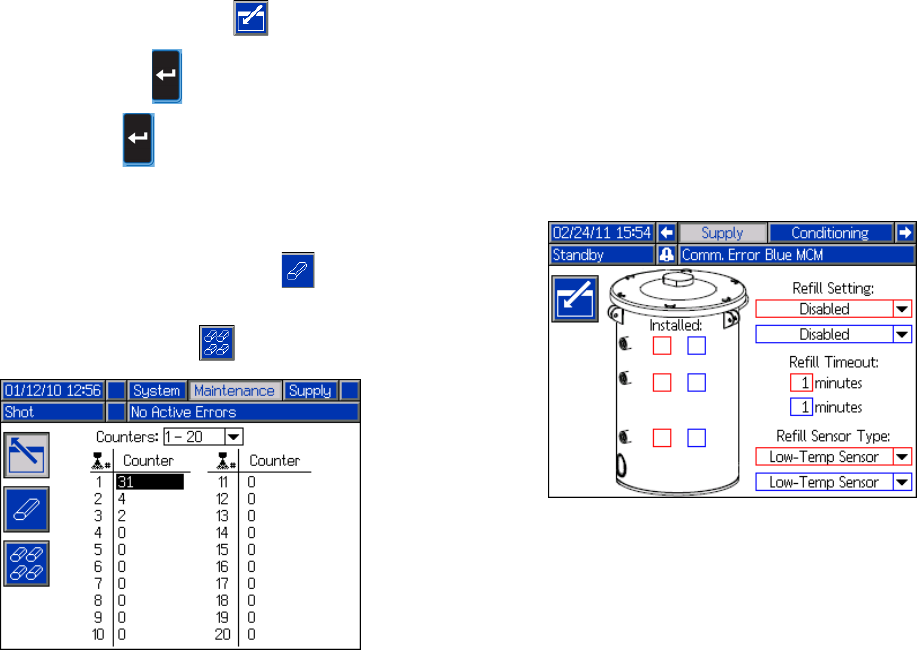
Appendix B - ADM Setup Screens Overview
76 313997W
Maintenance Screen
This screen shows shot number, sequence position, and
dispense valve counters. Press and navigate to the
drop down box. Press and scroll to a range of coun-
ters to view. Press again to select the range of
counters and display them on the screen.
Counters may be erased individually. Navigate to the
counter you want to erase and press . Alternatively,
each counter displayed on the page may be erased
simultaneously by pressing .
Supply Screen
This screen allows the user to specify the operating
parameters for off-board, integrated tanks and indicate
which positions have level sensors installed. See the
Tank Feed Systems manual for information about install-
ing level sensors, see Related Manuals on page 3. The
user may select from the following refill settings: Dis-
abled, Monitor, Manual, Auto Top-Off, Auto Full-Volume.
NOTE: Use the “Disabled” setting if off-board tanks are
not installed.
The following describes system operation when each
tank mode is selected.
•Disabled
• Disables tank operation
•Monitor
• The top sensor generates a high level deviation
and the bottom sensor generates a low level
alarm
• Refill is not supported, no button is provided on
the run screens to initiate refill
• Errors will clear when the corresponding condi-
tion clears
•Manual
• The low level sensor will generate a low level
alarm
• A button is provided to the user on the run
screens to instigate a manual refill operation at
any time
• Manual refill will run until either the high level
sensor sees material, the user aborts the refill
via the refill button on the run screens, or the
refill time-out expires
• The low level alarm will clear when the condition
clears
•Auto Top-Off
• The low level sensor will generate a low level
alarm
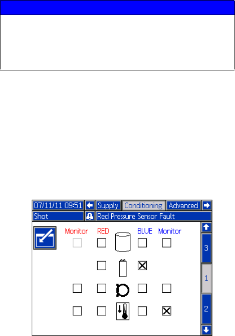
Appendix B - ADM Setup Screens Overview
313997W 77
• When the high level sensor does not see mate-
rial, automatic refill will begin and continue until
either the high level sensor sees material or
until the refill time-out expires
• The low level alarm will clear when the condition
clears
• A button is provided to the user on the run
screens to instigate an automatic refill operation
at any time, this button can also be used to
abort a refill operation
•Auto Full-Volume
• The low level sensor will initiate an automatic
refill when it does not see material
• Automatic refill will continue until either the high
level sensor sees material or until the refill
time-out expires
• The low level alarm will clear when the condition
clears
• A button is provided to the user on the run
screens to instigate an automatic refill operation
at any time, this button can also be used to
abort a refill operation
Refill Setting
If a refill setting other than Disabled is selected, the user
must set at least two level sensor locations as installed
by checking the check box on the screen. If all three
locations are set to installed, the system will default to
the Auto-Top Off refill setting and operate as follows:
• The low level sensor will generate a low level alarm.
• The high level sensor will generate a high level devi-
ation and abort any automatic refill operation.
• When the middle sensor is not satisfied, automatic
refill will begin and will run until either the middle
sensor is satisfied, the high level sensor generates a
deviation (if the middle sensor fails), or the refill
time-out expires.
• The low level alarm and the high level deviation will
clear when the condition clears.
• A button is provided to the user on the Run screens
to instigate an automatic refill operation at any time.
This button can also be used to abort a refill opera-
tion.
Refill Timeout
The refill time-out setting may be set by the user as a
means to abort the refill in the case of a high level sen-
sor failure. When an automatic refill begins, the time-out
counter will begin to count down. If the timer expires
before the high level sensor is satisfied, the refill will
abort.
Refill Sensor Type
The Low-Temp Sensor setting limits tank temperatures
to 150°F (66°C). And the High-Temp Sensor setting lim-
its tank temperatures to 190°F (88°C).
Conditioning Screen 1
This screen allows the user to select which temperature
conditioning components are installed in the system.
Check the box next to the component type for the appro-
priate side of the system to indicate that a component is
installed. A maximum of four components may be
selected. A maximum of four components and two mon-
itoring zones may be selected.
NOTICE
If you are using low temperature sensors and
select the High-Temp Sensor setting and set the
temperature above 150°F (66°C), damage to the
level sensors will occur.
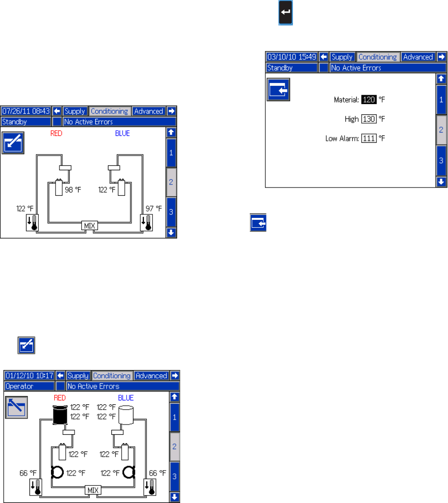
Appendix B - ADM Setup Screens Overview
78 313997W
Conditioning Screen 2
This screen shows the fluid path for the temperature
conditioning components and temperature setpoints for
each component.
NOTE: If tank blanket heaters or inline heaters are
installed along with hose heat, the hose heat setting will
be limited to at or below the inline or tank heat setting.
To edit the temperature setpoint and alarms for a partic-
ular component:
1. Press then use the arrow keys to navigate to
the component you wish to edit.
2. Press to display the setpoint and alarm values
associated with that component.
3. Edit the setpoint and alarm values and then press
to return to Conditioning Screen 2.
NOTE: The high alarm and low alarm values must be at
least +/-9°F (5°C) than the material temperature value.
N
OTE: All components are shown installed for refer-
e
nce only. Only 4 components can be installed at one
t
ime.
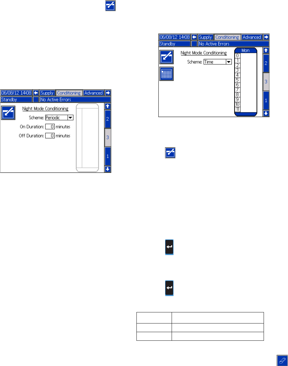
Appendix B - ADM Setup Screens Overview
313997W 79
Conditioning Screen 3
This screen allows the user to configure Night Mode
operation. In Night Mode, the system will cycle on and
off periodically or turn on at a preset time. Press
and select periodic or time schemes.
When the system is in Night Mode and in an “On” cycle,
the system will circulate in low pressure. The installed
conditioning zones will be on and controlling to their
respective setpoints. When the system is in Night Mode
and in an “Off” cycle, the system will be idle. The system
will not be circulating, and the conditioning zones will not
be actively controlling temperature. When in Night
Mode, supply tanks will not fill.
Time Based Night Mode Conditioning Screen
This screen allows the user to set a specific time each
day to turn the machine on or off. The times can be set
on or off by either each day separately, Monday through
Friday where each day has the same on or off times, or
Sunday through Saturday where each day has the same
on or off times. The days can be selected by pressing
the left or right arrow keys once entered into the screen.
To set the on/off machine times:
1. Press to enter the screen
2. Press left or right arrow keys to highlight the day
selection column. Continue to press the left or right
arrow keys to select the desired day, work week
(Monday thru Friday), or full week (Sunday thru Sat-
urday) duration.
3. Press the up or down arrow keys to select the
desired hour to schedule the on or off machine
times.
4. Press to enter the selected hour and select the
desired time (15 minute increments) for either
machine on or off to occur.
5. Press and select either on or off for the time
duration selected.
6. To erase times, repeat steps 1 thru 3 and press
once the desired time duration has been selected.
Bar Color Description
Green Machine is ON
Red Machine is OFF
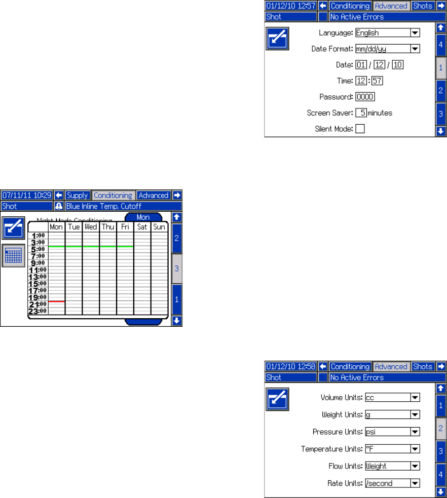
Appendix B - ADM Setup Screens Overview
80 313997W
NOTE: If times are entered in the weekly schedule, indi-
vidual days can not be erased.
Cold Start Up Mode
Allows the user to select what mode the machine will
enter once the cold start-up is complete. Selecting no
change will leave the machine in either standby or night
modes circulating at the set low pressure percentage.
Auto High Pressure
Changes the machine to high pressure circulation when
the mode is changed from either standby or night
modes.
Calender Time Based Night Mode Conditioning
Screen
This screen shows a summary of Time Based Night
Mode on or off times that were set by the Time Based
Night Mode Conditioning Screen.
Advanced Screen 1
This screen allows the user to set the language, date
format, current date, time, setup screens password,
screen saver delay, and turn on or off silent mode.
•Language: Available languages are English, Span-
ish, French, German, Chinese, Japanese, Korean,
Russian, and Italian.
•Time: formatted in 24 hour time.
•Password: Enables the setup screens to be pass-
word protected. Entering “0000” disables the fea-
ture.
•Screen Saver: Enter the amount of time until the
backlight turns off. Entering “0” leave it constantly
on.
•Silent Mode: Check this box to turn off the buzzer
for key presses.
Advanced Screen 2
This screen allows the user to set the units of measure.
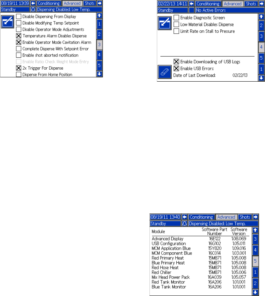
Appendix B - ADM Setup Screens Overview
313997W 81
Advanced Screen 3
This screen allows the user to control the availability of
some key system features.
•Disable Dispensing From Display: Check this box
to disable dispensing from the ADM. A footswitch,
dispense valve trigger, or other external signal will
be the only way to initiate a dispense.
•Disable Modifying Temp Setpoint: Check this box
to disable modifying temperature setpoints from the
Run screens. This is only applicable if temperature
control items are installed and enabled.
•Disable Operator Mode Adjustments: When this
box is checked, the user will not be able to adjust
the dispense settings in Operator Mode.
•Low Heater Temp Disables Dispense: When this
box is checked, the system will reject dispense
requests when any enabled heat zones are below
their setpoint.
•High Chiller Temp Disables Dispense: When this
box is checked, the system will disable dispensing
when any enabled chiller zones are above their set-
point.
•Operator Mode Cavitation Alarm: Check this box
to enable cavitation alarms in Operator Mode. Clear
this box to disable cavitation alarms in Operator
Mode.
•Complete Dispense with Setpoint Error: When
this box is checked, the shot will continue dispens-
ing even if the system never reaches the desired
setpoint.
•Enable Shot Aborted Notification: When this box
is checked, a pop-up notification will be displayed
when a shot is aborted.
•Enable Ratio Check Weight Mode Entry: This
option is for machines without flow meters. When
this box is checked, after any ratio check shot a
popup window will appear asking the user to enter
the dispensed weights. Press the Cancel button to
abort the entry or press the Enter button to record
the new values.
Advanced Screen 4
•Limit Rate on Stall to Pressure: Check this box to
allow the HFR to increase to stalling pressure at a
slower, more controlled rate.
•Enable Diagnostic Screen: Check this box to
enable the optional ADM screens, enabling USB log
downloading, and erasing USB logs. For more infor-
mation about USB operation, see Appendix F -
USB Operation on page 102. For more information
about the optional screens, see Diagnostic screen
on page 87.
•Low Material Disables Dispense: When this box is
checked, the current dispense will terminate and
prevent additional dispenses when the supply sys-
tem indicates a low level.
Advanced Screen 5
This screen displays software information.
Numbers shown are for reference only and may
be different on your system.
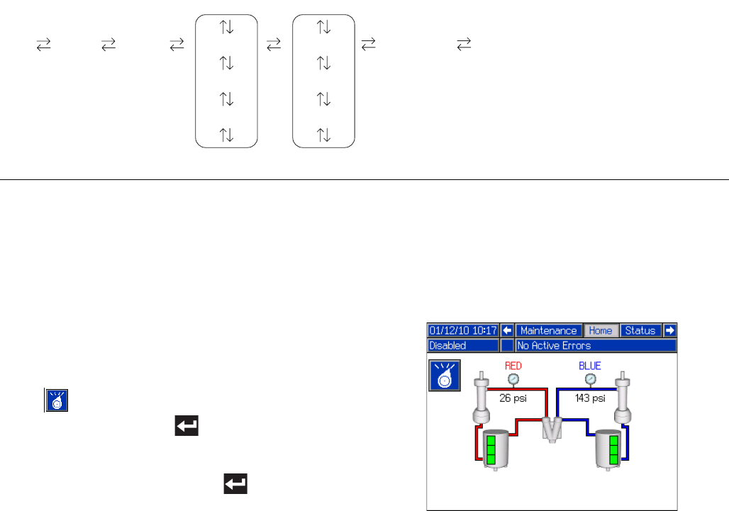
Appendix C - ADM Run Screens Overview
82 313997W
Appendix C - ADM Run Screens Overview
Run screens are divided into five major sections: status,
errors, events, and maintenance. The following diagram
demonstrates the flow of the Run screens beginning
with the Home screen.
Home Screen
The Home screen is the first screen that displays in the
Run screens. It shows the current fluid pressure on the
A (Red) and B (Blue) fluid outlets of the pump and if
there are any active errors. If tanks are installed in the
system, the fill level is shown on each tank. The ratio is
also displayed as either Red:1 or Blue:1 depending on
which display has been setup.
To select an operating mode, press the Select Mode
button repeatedly until the desired mode is shown
then press the Enter button to select the mode.
Alternately, press the Select Mode button and use the
up and down arrow keys until the desired mode is
shown, then press the Enter button to select the
mode. The available operating modes are operator,
sequence, shot, standby, night, and disabled.
Home Screen, Disabled Mode
When this mode is selected, the machine will not be
able to dispense or condition (heat/cool) material. The
setup screens cannot be accessed while in Disabled
mode. Use the Select mode button to exit Disabled
mode.
FIG. 23: Run Screens Navigation Diagram
Maintenance
Home Status Events #1
Events #2
Events #...
Errors #1
Errors #2
Errors #...
* Supply tanks shown for reference only. Your sys-
tem may not include supply tanks.
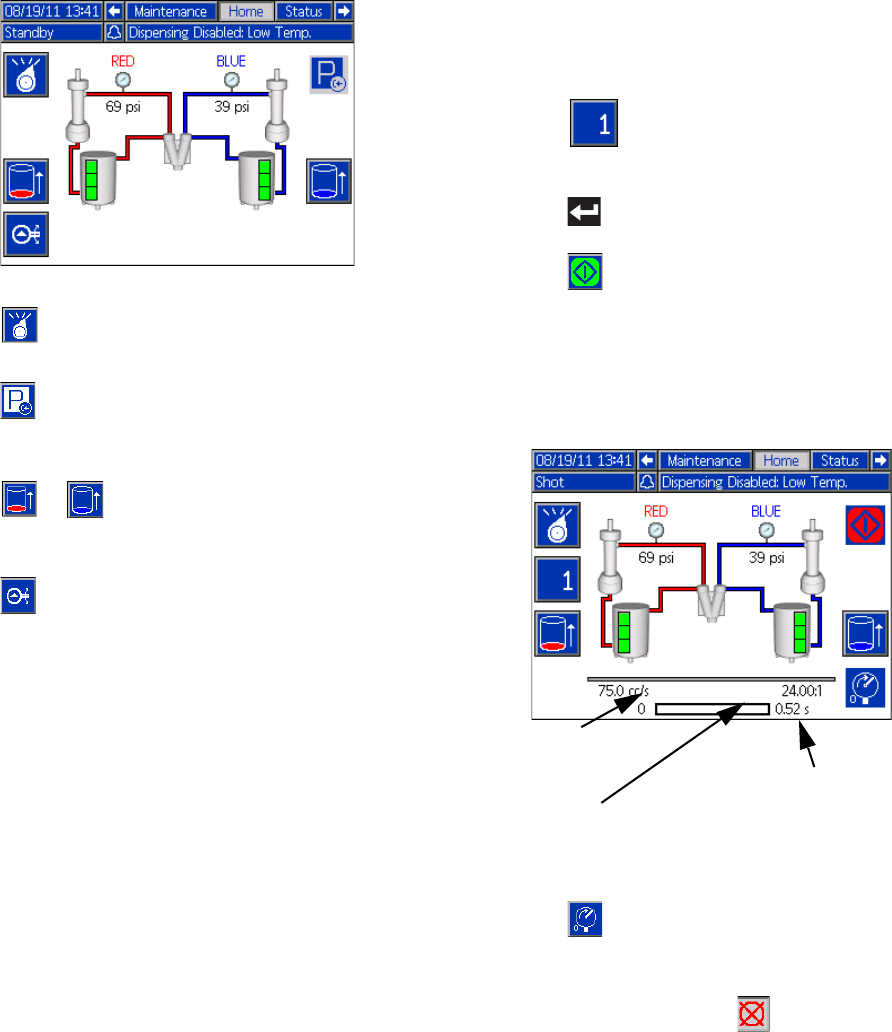
Appendix C - ADM Run Screens Overview
313997W 83
Home Screen, Standby Mode
In Standby Mode, the user can enable heating, park the
pumps, refill the tanks, circulate materials.
Press to change operating modes.
Press to move the pumps all the way to the left and
turns the hydraulic power pack off.
Press or to initiate a tank refill. If a tank is fill-
ing, pressing either button will abort the filling operation.
Press to stop or start the hydraulic power pack and
run the start-up process.
Home Screen, Shot Mode
This mode allows the user to select one of 100 pre-
defined shot numbers. See Shots Screen on page 69
for information about editing shot definitions.
To use a predefined shot:
1. Enter shot mode.
2. Press and use the numeric keypad to enter
the desired shot number.
3. Press to select the shot number.
4. Press to initiate a dispense. The system will go
to high pressure mode and dispense a shot after the
pre-dispense timer, see Mix Head Operating
Details Screen on page 74, expires.
NOTE: There is a three second delay after a dispense
before another dispense can be initiated
5. Press to switch between low and high pressure
modes without dispensing.
6. During a dispense, press to abort the dispense.
7. See Home Screen, Standby Mode on page 83 for
other button functions.
Tar g e t F l o w
Ratio
Target recipe time
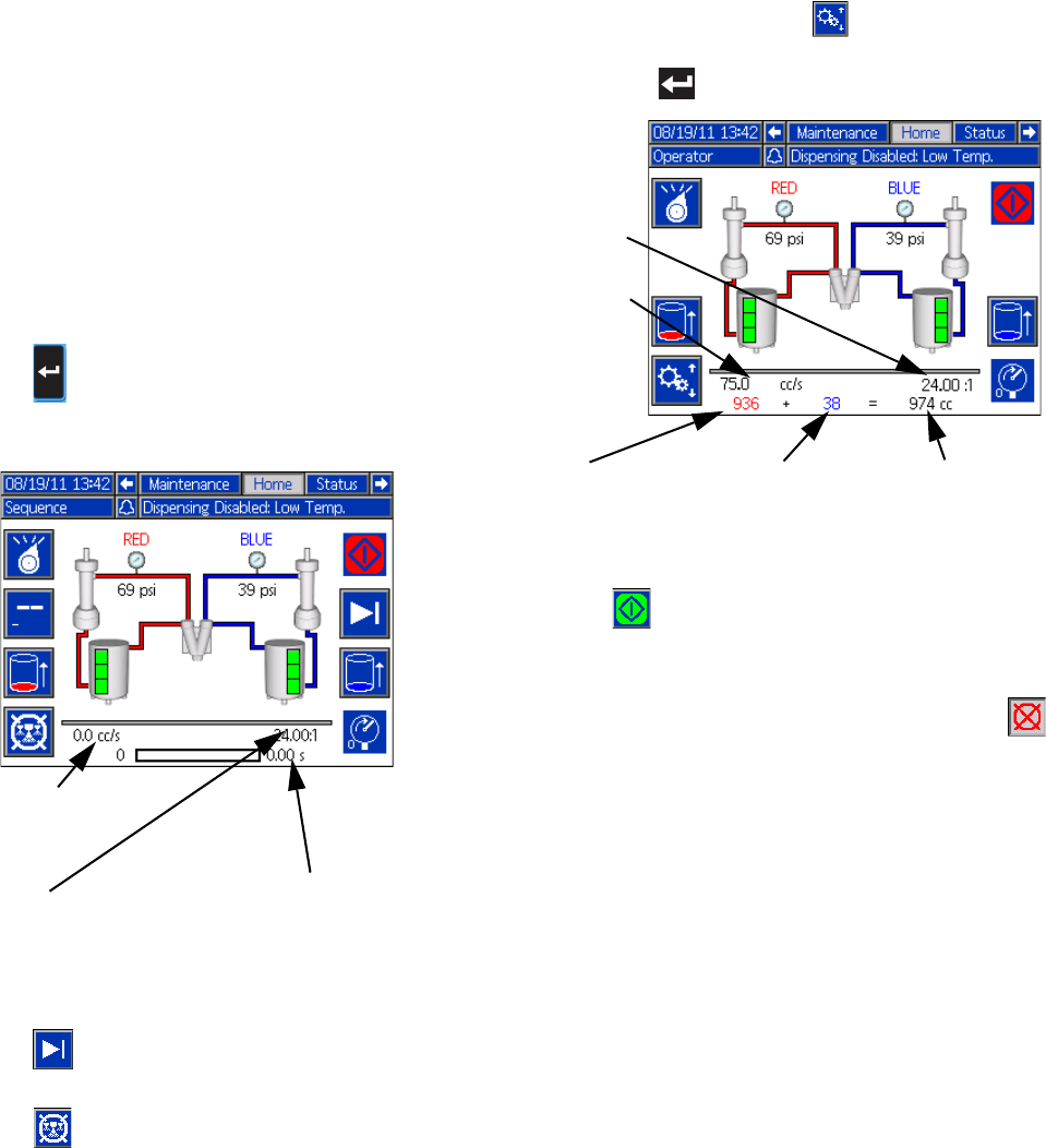
Appendix C - ADM Run Screens Overview
84 313997W
Home Screen, Sequence Mode
This mode allows the user to select one of five
sequences (A-E). The progress bar on the bottom of the
screen shows the progress of a shot dispensing from
the selected sequence. See Sequences Screen on
page 71 for information about editing sequence defini-
tions.
To use a predefined sequence:
1. Enter Sequence Mode.
2. Press the sequence letter/position selection button.
3. Use the left and right arrows to toggle between letter
and position selection. When selecting a sequence
letter (A-E), use the up and down arrow keys to
scroll through the available letters. When selecting a
sequence position, type in the desired position with
the numeric keypad. The system will reject invalid
letter/position selections.
4. Press to accept the sequence letter/position.
5. Press the Dispense button to begin dispensing.
6. Press to skip to the next sequence position.
7. Press to abort the sequence.
8. See Home Screen, Shot Mode on page 83 for
other button functions.
Home Screen, Operator Mode
This mode allows users to set a pressure or flow rate to
dispense material without using predefined shot infor-
mation. Pressure or flow rate availability is dependent
on the Control Mode selection, see System Screen 2
on page 73.
1. To edit the flow rate, press . The value to
change will now be highlighted. Type the new value
then press to accept it.
2. Press to initiate a dispense. The system will go
to high pressure mode and dispense a shot after the
pre-dispense timer, see Mix Head Operating
Details Screen on page 74, expires. Press the
to stop the dispense.
NOTE: There is a three second delay after a dispense
before another dispense can be initiated.
3. If an external trigger is used, press an hold the trig-
ger to initiate a dispense. Release the trigger to stop
the dispense.
4. See Home Screen, Shot Mode on page 83 for
other button functions.
Ta r g e t
Flow/Pressure
Ratio Target dispense amount (time/vol-
ume/weight depending on Dis-
pense Mode)
Total of resetta-
ble material
counters
B (Blue) reset-
table material
counter
A (Red) resetta-
ble material
counter
Operator
Setting
Ratio
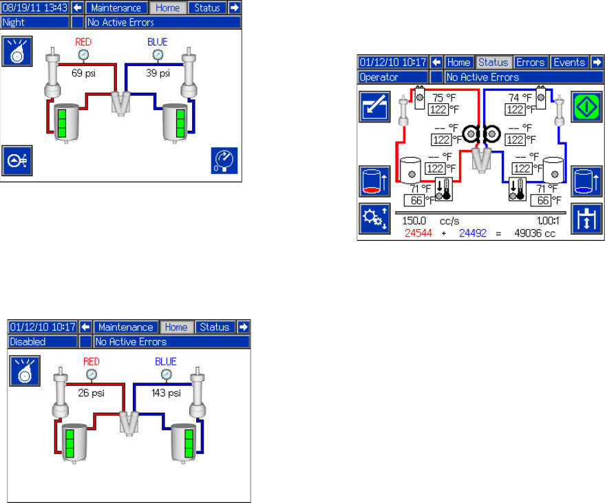
Appendix C - ADM Run Screens Overview
313997W 85
Home Screen, Night Mode
In Night Mode, the system will cycle on and off
periodically. The recirculation on/off cycle begins
automatically upon entering Night Mode. See
Conditioning Screen 3 on page 79.
Home Screen, Disabled Mode
When this mode is selected, the machine will not be
able to dispense or condition (heat/cool) material. The
setup screens cannot be accessed while in Disabled
mode. Use the Select mode button to exit Disabled
mode.
Status Screen
The status screen provides all of the operational func-
tionality of the Home screen except for operating mode
selection. Refer to the Home screen and operating
mode descriptions for information on this functionality.
In addition to the functionality provided by the Home
screen, the Status screen also provides material condi-
tioning information and control.
◆No setpoint box will be displayed if selected as moni-
tor zone.
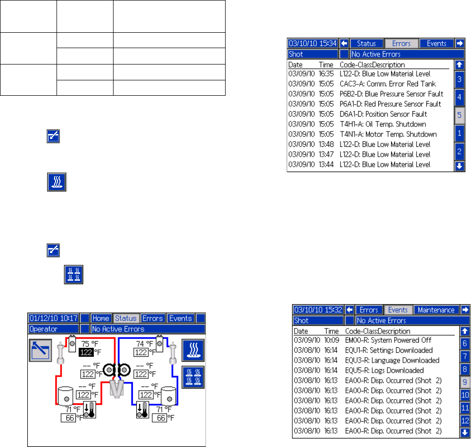
Appendix C - ADM Run Screens Overview
86 313997W
Status Screen, Conditioning Control
This screen allows users to turn on and off heat zones
individually or all at once. When a zone is on it is actively
controlling temperature. Refer to the table below for
color code definitions.
To turn a single zone on/off:
1. Press to enter the Conditioning Control screen.
2. Use the arrows keys to navigate to the desired zone.
3. Press to turn the selected zone on. When a
zone is on, the button will be selected. Press the
button again to turn the zone off.
To turn all zones on/off:
1. Press to enter the Conditioning Control screen.
2. Press the to turn on all zones. When one or
more zones are on, the button will be selected.
Press the button again to turn all zones off.
◆No setpoint box will be displayed if selected as moni-
tor zone.
Errors Screens
This screen shows users a list of errors that have
occurred in the system. Each error entry includes a
description and error code along with a date and time
stamp. There are 5 pages, each holding 10 errors. The
50 most recent errors are shown.
Refer to the Troubleshooting section on page 58 for a
detailed description of all of the system errors.
Events Screens
This screen shows users a list of events that have
occurred in the system. Each event includes a descrip-
tion and event code along with a date and time stamp.
There are 20 pages, each holding 10 events. The 200
most recent events are shown.
Refer to the Troubleshooting section on page 58 for a
detailed description of all of the system events.
Zone
Setting Color Definition
OFF Black Dispense Disabled
Grey Dispense Allowed
ON Yellow Dispense Disabled
Green Dispense Allowed
All zones shown for reference. Only four zones may
be active at one time.
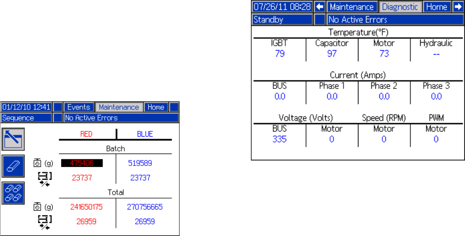
Appendix C - ADM Run Screens Overview
313997W 87
Maintenance Screen 1
This screen displays historical information for each
pump in the system. The Batch counters are resettable
and count both material usage and pump cycles. The
Total counters are not resettable by the user. They also
count both material usage and pump cycles. For mate-
rial usage counters, units are displayed next to the vol-
ume/weight indicator icons.
To erase a batch counter, press the Enter Screen button
and navigate to the field to be erased. Press the Erase
Single button to erase that data point. Alternatively, the
Erase All button may be pressed to erase all of the batch
data points simultaneously.
NOTE: In a circulation system, the pumpline must be
stopped to erase counters.
Optional Screens
The optional Diagnostic screen can be enabled in the
Advanced Screen 4 screen, see page 81.
Diagnostic
The Diagnostic screen shows status information for vari-
ous system components.

Appendix D - ADM Error Codes
88 313997W
Appendix D - ADM Error Codes
Error
Code Error Name Error Description
Error
Type Cause Solution
A4H3
Mix Head
Motor
Overload
Refer to AC Power Pack manual
DEH3 Soft Stop
Asserted
MBH3
Low Mix
Head Oil
Level
P1H3
Low
Accumulator
Pressure
P4H3
High
Accumulator
Pressure
T4H3
High Mix
Head Oil
Temp.
WDF3 M1 Material
Rod Shift Fail
WDD3 M1 Cleanout
Rod Shift Fail
0500
Invalid
Weight Cal.
Data
The three point calibration data
is invalid, system will operate
in weight mode but will attempt
to volumetrically calculate
weight. This will lead to
consistent shots which will be
offset for the desired dispense
amount.
Deviation Invalid data Re-calibrate the machine
02D0 Low Flow
Advisory Pump velocity is too low. Advisory
Pump flow setpoint is
lower than one eighth of
the total pump volumes
Increase the pump flow setpoint
A4A6 Red Blanket
Overcurrent
An over current was detected
on the output Alarm
Bad heaters Measure resistance of heater
A4B5 Blue Blanket
Overcurrent
A4A3 Red Inline
Overcurrent
A4B1 Blue Inline
Overcurrent
A4A2 Red Hose
Overcurrent
A4B4 Blue Hose
Overcurrent
A4A7 Red Chiller
Overcurrent High voltage Measure voltage across the disconnect switch.
Voltage should measure between 190 and 264 Vac.
A4B8 Blue Chiller
Overcurrent
Shorted Temperature
Control Module
If temperature rises for a zone that has been disabled,
replace Temperature Control Module
A4H1 Motor Over
Current
High current has been
detected on a phase and has
been shutdown to prevent
damage
Alarm
Bad internal wiring of the
motor Replace motor
Short circuit of motor
wiring
Check wiring to the motor to ensure no bare wires are
touching and that no wires are shorted to ground
A4M1 Motor Over
Current
Too much current is being
drawn from the wall Alarm Low voltage from the wall
during load
Make sure the supply line is properly sized for the
load and is above the minimum voltage requirements

Appendix D - ADM Error Codes
313997W 89
A4N1 Motor Over
Current
A hardware current fault has
occurred causing a system
shutdown
Alarm
Short circuit of motor
wiring
Check wiring to the motor to ensure no bare wires are
touching and that no wires are shorted to ground
Motor rotor has become
locked
Unplug the directional valve (so pressure will not
build) and try to move the motor again. If this
succeeds then the power pack may need to be
replaced. If the motor is still unable to move, the
bearings or hydraulic pump have likely failed in the
motor and will need to be replaced.
A7A6 Red Blanket
Control Fault
Unexpected current to
heater/chiller Alarm Shorted Temperature
Control Module
If temperature rises for a zone that has been disabled,
replace Temperature Control Module
A7B5 Blue Blanket
Control Fault
A7A3 Red Inline
Control Fault
A7B1 Blue Inline
Control Fault
A7A2 Red Hose
Control Fault
A7B4 Blue Hose
Control Fault
A7A7 Red Chiller
Control Fault
A7B8 Blue Chiller
Control Fault
A8A6
No Red
Blanket
Current
No current to the conditioning
zone Alarm
Tripped circuit breaker Visually check circuit breaker for a tripped condition
A8B5
No Blue
Blanket
Current
A8A3 No Red Inline
Current
A8B1 No Blue Inline
Current
A8A2 No Red Hose
Current
A8B4 No Blue Hose
Current Low power
Measure voltage across input terminals on power line
filter. Voltage should measure between 190 and 264
Vac
A8B7
No Red
Chiller
Current
Cable unplugged/loose
power Check for loose or disconnected wires or plugs
A8B8
No Blue
Chiller
Current
Bad heater(s) Measure resistance of heater(s)
A9C1 Motor Over
Current
A software error has occurred
commanding too much current Alarm Bad Motor Control
Module code
Check for MCM software update, load latest MCM
software, if problem persists contact Graco
B9C0
Small Shot
Request
The requested dispense
amount is below the minimum
amount of the system (25% of
the combined pump volumes is
the minimum) Deviation
Pumps are defined with
the wrong size
On the ADM go into the Setup screens to the System
screens then make sure that the pump sizes are
defined correctly
Requested shot is below
the capabilities of the
current pump setup
If the user has to be able to take the shot the system
must be fitted with smaller pumps
B9C1 The requested dispense
amount (time/volume/weight)
is below the minimum amount
of the system
Short shot size Increase the time/volume/weight of the shot
Error
Code Error Name Error Description
Error
Type Cause Solution

Appendix D - ADM Error Codes
90 313997W
CAA2 Comm. Error
Red Hose
Communication error Alarm
Module missing power Check power supply connection
CAA3 Comm. Error
Red Inline Module not programmed Program the module
CAA6 Comm. Error
Red Blanket
Module bad Replace module
CAA7 Comm. Error
Red Chiller
CAB1 Comm. Error
Blue Inline
CAB4 Comm. Error
Blue Hose
CAB5 Comm. Error
Blue Blanket
CAB8 Comm. Error
Blue Chiller
CAC1 Comm. Error
Motor
CAC2 Comm. Error
MCM
CAC3 Comm. Error
Red Tank
CAC4 Comm. Error
Blue Tank
CAC5 Comm. Error
Mix Head
CAC6 Comm. Error
Mix Head 2
CAC7 Comm. Error
Ratio Monitor
CACN Comm. Error
Gateway
CACP Comm. Error
DGM
CACR
Comm. Error
Remote
Pendant
CUCN
Gateway
Heartbeat
Error
Heartbeat Error Alarm
PLC is not maintaining
heartbeat Ensure PLC is triggering the heartbeat
Module missing power Check power supply connection
Module not programmed Program the module
Module Bad Replace module
D1A1 Setpoint Not
Reached
The set point was not reached
and the pump was shutdown Deviation Material restriction too
high for requested flow Reduce flow request
D4A1 Setpoint
Exceeded
The maximum cycles per
minute of the pump has been
exceeded
Deviation Restriction for the pump
is not sufficient Increase the restriction or lower the set point
D2A1 Setpoint Not
Reached The set point was not reached Deviation
Pump cannot reach the
requested pressure Increase restriction in the system
Pump cannot reach the
requested flow Decrease restriction in the system
D3A1 Setpoint
Exceeded The set point was exceeded Deviation
System underwent a
change that caused a
large drop in restriction
(such as new orifices)
Erase learned System Data, found in the setup
screens under calibration
No material in pumps Make sure the material lines are open and have
proper feed pressure
Error
Code Error Name Error Description
Error
Type Cause Solution

Appendix D - ADM Error Codes
313997W 91
D5A1 Invalid Learn
Mode Data
This calibration lets the MCM
know where the ends of the
pump are. If the data gathered
during this process is outside
of normal parameters the
machine will operate with a
greatly reduced stroke.
Deviation
Recalibrate the machine Rerun the learn mode calibration
Loose/bad connection Check to ensure the pressure transducer is properly
installed and all wires are properly connected
Bad linear position
sensor
Verify pump moves to limits, if problem persists
replace linear position sensor
D6A1 Position
Sensor Fault
The linear position sensor is
returning data that should not
be possible during normal
operation
Alarm
Loose/bad connection to
linear position sensor
Check to ensure the linear position sensor is properly
installed and all wires are properly connected
Bad linear position
sensor Replace linear position sensor
Linear position sensor
may be loose where
attached to pump
housing
Re-tighten the sensor and re-calibrate the machine
DDA1 Red Pump
Cavitation
Cavitation was detected on the
given pump Deviation
Insufficient material
being supplied or
insufficient material
pressure on feed system
Verify that incoming ball valves are open
DDB2 Blue Pump
Cavitation
Verify that feed pumps are supplying material
Debris or packout in the
incoming fluid filter
Inspect filter for debris of filler packout and clean or
replace as necessary
DFA1 Pump Not
Parked
The pump failed to reach the
park position Deviation
Orifices blocked Clear blockage
Hose blocked Clear or replace hose as necessary
Dispense valve failed to
open
Check to make sure the dispense valve is properly
configured and connected to the MCM
DR6A Check Flow
Meter Red Flow Meter has caused a fault Deviation
Cogs in flow meter are
not turning
Check that flow meter is matched to nominal pump
output
DR6B Check Flow
Meter Blue
Cable unplugged/loose
power check of loose or disconnected wires or plugs
DSC0 Pumps Not
Defined
The type or size of the Red or
Blue material pumps have not
been defined
Alarm Properly setup the
system
On the ADM go into the setup screens -> System->
then make sure that the pump type and size are set
(not --)
F1A0 Low Flow
Red Flow is below the defined low
limit
Alarm Cogs in flow meter are
not turning
Check that flow meter is matched to nominal pump
output
F2A0 Deviation
F1B0 Low Flow
Blue
Alarm Cable unplugged/loose
power Check for loose or disconnected wires or plugs
F2B0 Deviation
F4A0 High Flow
Red Flow is above the defined low
limit
Alarm
Cogs in flow meter are
turning rapidly
Check that flow meter is matched to nominal pump
output
F3A0 Deviation
F4B0 High Flow
Blue
Alarm
F3B0 Deviation
F7D1 Pump Failed
to Stall
When the pump tried to stall to
pressure the pump traveled
more than it should in normal
operation (only applies to
dead-headed system)
Deviation
Failure of the dispense
valve
Ensure the valve has a proper air supply and seals
properly. If not, service the valve as necessary.
Material leak
Visually inspect the machine and hoses for sign of
leakage. NOTE: This error will display after 2 full
piston strokes so the leak will be substantial.
Out of material Fill tanks
L111 Red Low
Material Level
Low material level in tanks Deviation
Tanks low on material Fill tanks with material
L122 Blue Low
Material Level
Loose/broken connection
If the tanks appear to have plenty of material check to
make sure the level sensor is connected to the proper
port and that the cord is not damaged
Bad level sensor Replace level sensor
L311 Red High
Material Level High material level in tanks Deviation Defective fill valve
If the tanks appear to have plenty of material check to
make sure the level sensor is connected to the proper
port and that the cord is not damaged
L322 Blue High
Material Level
L6A1 Red Auto
Refill Timeout The tank stand has been filing
for a time greater than
expected
Deviation
No material is actually
being fed Make sure the feed pumps are operating properly
L6B2 Blue Auto
Refill Timeout
Loose level sensor
connection Check for loose or disconnected wires or plugs
Bad level sensor Replace level sensor
Error
Code Error Name Error Description
Error
Type Cause Solution

Appendix D - ADM Error Codes
92 313997W
L8A1
Red Tank
Sensor
Failure A level sensor had ceased
working Deviation Bad level sensor Replace level sensor
DR6B
Blue Tank
Sensor
Failure
MBH1 Low Oil Level
The volume of oil in the tank is
below the minimum level
needed for the system to
properly operate
Alarm
Low oil level Check oil level and if low add more hydraulic fluid
Loose/bad connection
Check to ensure the hydraulic oil level sensor is
properly connected to the MCM and that the wire has
not been damaged
Bad level sensor Replace sensor
Leak in hydraulic driver
Inspect hydraulic driver end seals and early leak
detection tubing. Replace seals as necessary and
replace lost oil.
Leak in the hydraulic
reservoir, heat
exchanger
Inspect the hydraulic reservoir fittings and filter for
leaks. Repair or replace as necessary and replace
lost oil.
MBN1 Low Motor
Performance
The motor magnetism has
decreased to the point where
performance is greatly reduced
Advisory Prolonged exposure to
heat or high voltage
If error persists and performance can no longer
satisfy the user requirements the motor will need to
be replaced
MMUX USB Logs
Full
USB log has reached the
maximum entries Advisory USB logs have not been
downloaded
Download USB logs to a memory stick
Uncheck the Enable USB errors on Advanced screen
4
N1D0
Material
Dispense
Below Alarm Material dispense is below the
defined limit
Alarm
Cogs in flow meter are
not turning
Check that flow meter is matched to nominal pump
output
N2D0
Material
Dispense
Below
Deviation
Deviation
N3D0
Material
Dispense
Above
Deviation Material dispense is above the
defined limit
Deviation
Cable unplugged/loose
power check for loose or disconnected wires or plugs
N4D0
Material
Dispense
Above Alarm
Alarm
N4A1 Pump Failed
to Move
The MCM attempted to move
the pump but no movement
was detected
Deviation
Motor failure Visually check to ensure the pump is moving, if not
ensure the motor is wired properly
Hydraulic power pack
failure
If motor is moving but pump is not and pressure is not
building they hydraulic power pack may need
servicing
Loose/bad connection to
the linear position sensor
Check to ensure the linear position sensor is properly
connected to the MCM and the wiring has not be
damaged
Failure of the linear
position sensor Replace the linear position sensor
Motor no longer coupled
to hydraulic pump
Reset coupler per specifications and retighten set
screws
Supply tube from
hydraulic pump to
manifold is loose or
broken
Retighten or replace supply tube
Broken motor shaft Replace motor
Over-pressure valve
dumping to tank
Verify that no outside forces are stopping the pump
from moving, then inspect over-pressure valve for
damage or debris
P400
Thermal
Pressure
Rise
Pressure has risen to an
unsafe level due to thermal
expansion of materials. All
conditioning zones have
automatically been turned off.
Deviation High pressure Open the dispense valve manually or open the valves
to bleed pressure
Error
Code Error Name Error Description
Error
Type Cause Solution

Appendix D - ADM Error Codes
313997W 93
P4A1 Red Pressure
Shutdown
The material pump pressure
exceeded the maximum
operating pressure as defined
in the setup screens
Alarm
Dispense valve failed to
open
Check to make sure the dispense valve is properly
configured and connected to the MCM
P4B2
Blue
Pressure
Shutdown
Bad dispense valve Replace dispense valve
Restriction in the
material lines Check to ensure there is no blockage
Invalid maximum
pressure defined
Make sure the requested pressure is within the max
operating pressure, which can be found on the setup
screen System 1
Orifices blocked Clear blockage
Hose blocked Clear blockage or replace hose as necessary
Dispense valve failed to
open
Check to make sure the dispense valve is properly
configured and connected to the MCM
P4D0 Pressure
Imbalance
The pressure difference
between the Red and Blue
material is greater than the
defined amount
Alarm
Dispense line is clogged Ensure the material flow is equally restricted on both
material lines
Pressure imbalance is
defined too low
On the ADM go into the setup screens -> System->
and ensure the pressure imbalance value is the
maximum acceptable to prevent unnecessary alarms
which will abort dispenses
Orifice blocks closed off
too much on one or both
sides
Verify that one or both of the orifice blocks dispense
when adjusted to the fully open position then adjust
accordingly
Debris in the orifice block Relieve system pressure then remove the orifice from
the orifice block and inspect for debris in the cavity
Material fillers may have
packed out in an orifice
Relieve system pressure and remove the orifice from
the orifice block and inspect for pack out. Clean or
replace as necessary.
Out of material Fill tanks with material
Feed system defective Replace defective item
P6A1 Red Pressure
Sensor Fault The pressure sensor is
providing invalid/no pressure
readings
Alarm Loose/bad connection Check to ensure the pressure transducer is properly
installed and all wires are properly connected
P6B2
Blue
Pressure
Sensor Fault
Alarm
Bad sensor Replace pressure transducer
No material in pump Fill tanks
R1D0 Low Ratio
Alarm
Ratio monitor has detected an
out of ratio condition
Alarm
Material A to Material B
is out of ratio Check feed system
R4D0 High Ratio
Alarm
R2D0 Low Ratio
Deviation Deviation
R3D0 High Ratio
Deviation
Error
Code Error Name Error Description
Error
Type Cause Solution

Appendix D - ADM Error Codes
94 313997W
T1A6
Red Tank
Low Fluid
Temp.
Fluid temperature is below the
defined low alarm limit Alarm
Tripped circuit breaker Visually check circuit breaker for a tripped condition
T1B5
Blue Tank
Low Fluid
Temp.
T1A3
Red Inline
Low Fluid
Temp.
T1B1
Blue Inline
Low Fluid
Temp.
T1A2
Red Hose
Low Fluid
Temp.
T1B4
Blue Hose
Low Fluid
Temp.
Low power
Measure voltage across input terminals on power line
filter. Voltage should measure between 190 and 264
Vac
T1A7
Red Chiller
Low Fluid
Temp.
Cable unplugged/loose
power Check for loose or disconnected wires or plugs
T1B8
Blue Chiller
Low Fluid
Temp.
Bad heater(s) Measure resistance of heater(s)
T20X
Dispensing
Disabled Low
Temp Dispensing disabled because
of temperature Advisory Temperature is out of
alarm limits Check temperature alarm limits
T30X
Dispensing
Disabled High
Temp
Error
Code Error Name Error Description
Error
Type Cause Solution

Appendix D - ADM Error Codes
313997W 95
T2AA
Red Hose
Low Fluid
Temp.
Fluid temperature for a monitor
zone is below the defined low
alarm limit
Deviation
Temperature is out of
alarm limits Check temperature alarm limits
T2AE
Red Tank
Low Fluid
Temp.
T2AF
Red Chiller
Low Fluid
Temp.
T2BC
Blue Hose
Low Fluid
Temp.
T2BD Blue tank Low
Fluid Temp.
Cable unplugged/loose
power Check for loose or disconnected wires or plugs
T2BG
Blue Chiller
Low Fluid
Temp.
T3AA
Red Hose
High Fluid
Temp.
Fluid temperature for a monitor
zone is above the defined high
alarm limit
T3AE
Red Tank
High Fluid
Temp.
T3AF
Red Chiller
High Fluid
Temp.
Inline heater is not turned
on Turn on inline heater
T3BC
Blue Hose
High Fluid
Temp.
T3BD
Blue Tank
High Fluid
Temp.
T3BG
Blue Chiller
High Fluid
Temp.
T3H1 Oil Temp.
Cutback
The hydraulic oil temperature
is approaching a level where
damage is possible so the
Motor Control Module is
limiting the output to a safe
level
Deviation
No power to fan Check cord to make sure fan has power
Debris is fan or fan grill Clear debris from fan/fan grill
Low air volume from fan
Try to stop fan by lightly pressing on the center with a
pencil eraser. If the fan slows down easily it will need
to be replaced
T3N1 Motor Temp.
Cutback
Motor temperature is
approaching a level where
damage is possible so the
motor control module is limiting
the output to a safe level
Advisory
No power to fan Check cord to make sure fan has power
Debris is fan or fan grill clear debris from fan/fan grill
Low air volume from fan
Try to stop fan by lightly pressing on the center with a
pencil eraser. If the fan slows down easily it will need
to be replaced
Ambient environmental
conditions are too hot Move machine to an area below 120°F
Motor/pump coupler may
be rubbing on hydraulic
pump
Reset coupler per specifications and retighten set
screws
Error
Code Error Name Error Description
Error
Type Cause Solution

Appendix D - ADM Error Codes
96 313997W
T4A2
Red Hose
High Fluid
Temp.
Fluid temperature is above the
defined high alarm limit Alarm
Defective Temperature
Control Module Replace Power Temperature Control Module
T4A3
Red Inline
High Fluid
Temp.
T4A6
Red Tank
High Fluid
Temp.
T4A7
Red Chiller
High Fluid
Temp.
T4B1
Blue Inline
High Fluid
Temp.
T4B4
Blue Hose
High Fluid
Temp.
T4B5
Blue Tank
High Fluid
Temp.
Defective RTD Replace RTD
T4B8
Blue Chiller
High Fluid
Temp.
Loose connections Tighten connections
T4C1 Motor Control
High Temp.
The temperature the MCM has
reached a level where product
life will be decreased
drastically and has been
shutdown for protection
Alarm
No power to fan Check cord to make sure fan has power
Debris is fan or heatsink Clear debris from fan or heatsink
Low air volume from fan
Try to stop fan by lightly pressing on the center with a
pencil eraser. If the fan slows down easily it will need
to be replaced
Motor may be damaged Replace motor
Debris is packed in the
MCM’s heat sink fins Clear debris from MCM heat sink fins
T4H1 Oil Temp.
Shutdown
The hydraulic oil is at a
temperature where
performance is impacted
significantly and has resulted
in a system shutdown
Alarm
No Power to Fan Check cord to make sure fan has power
Debris in fan or fan grill Clear debris from fan/fan grill
Low air volume from fan
Try to stop fan by lightly pressing on the center with a
pencil eraser. If the fan slows down easily it will need
to be replaced
T4N1 Motor Temp.
Shutdown
Motor temperature is too high
and system has been
shutdown to prevent possible
damage
Alarm
No power to fan Check cord to make sure fan has power
Debris is fan or fan grill Clear debris from fan/fan grill
Low air volume from fan
Try to stop fan by lightly pressing on the center with a
pencil eraser. If the fan slows down easily it will need
to be replaced
Ambient environmental
conditions are too hot Move machine to an area below 120°F
Motor may be damaged Motor may need to be replaced
T6A6 Red Tank
RTD Fault
RTD 1 is giving no or invalid
data Alarm
Loose or bad connection Check RTD wiring
T6B5 Blue Tank
RTD Fault
T6A3 Red Inline
RTD Fault
T6B1 Blue Inline
RTD Fault
T6A2 Red Hose
FTS Fault
T6B4 Blue Hose
FTS Fault
T6A7 Red Chiller
RTD Fault
T6B8 Blue Chiller
RTD Fault Bad RTD Replace RTD
Error
Code Error Name Error Description
Error
Type Cause Solution

Appendix D - ADM Error Codes
313997W 97
T6C6 Red Blanket
RTD Fault
RTD 2 is giving no or invalid
data Alarm
Loose or bad connection Check RTD wiringT6C5 Blue Blanket
RTD Fault
T6C7 Red Chiller
RTD Fault
T6C8 Blue Chiller
RTD Fault Bad RTD Replace RTD
T8A6 No Heat Red
Tank
No temperature rise Alarm
Tripped circuit breaker Visually check circuit breaker for a tripped conditionT8B5 No Heat Blue
Tank
T8A3 No Heat Red
Inline
T8B1 No Heat Blue
Inline Low Power
Measure voltage across input terminals on power line
filter. Voltage should measure between 190 and 264
Vac
T8A2 No Heat Red
Hose
Cable unplugged/loose
power Check for loose or disconnected wires or plugs
T8B4 No Heat Blue
Hose Bad heater(s) Measure resistance of heater(s)
T8A7 No Cooling
Red Chiller
No temperature decline Alarm
Tripped circuit breaker Visually check circuit breaker for a tripped condition
T8B8 No Cooling
Blue Chiller
Defective cooling valve
Disconnect the valve and measure the voltage across
the wires when the chiller is running to ensure 24V is
being delivered to the valve. If so, the cooling valve
will likely need replacing.
Chilled water supply off Turn on chilled water supply
Loose or bad connection Check RTD wiring
T9A6 Red Blanket
Temp. Cutoff
Heater overtemperature cutoff Alarm
Defective RTD Replace RTD
T9B5 Blue Blanket
Temp. Cutoff
T9A3 Red Inline
Temp. Cutoff
Defective High Power
Temperature Control
Module
Replace High Power Temperature Control Module
T9B1 Blue Inline
Temp. Cutoff Loose connections Tighten connections
T9C6
Red Blanket
Ctrl
Shutdown
PCB over temperature Alarm
Overheated
Temperature Control
Module
Turn conditioning zone off. Wait a few minutes. If the
condition does not clear or regenerates consistently,
replace heater module
T9C5
Blue Blanket
Ctrl
Shutdown
T9C3
Red Inline
Ctrl
Shutdown
T9C1
Blue Inline
Ctrl
Shutdown
T9C2 Red Hose Ctrl
Shutdown
T9C4
Blue Hose
Ctrl
Shutdown
T9C7
Red Chiller
Ctrl
Shutdown
T9C8
Blue Chiller
Ctrl
Shutdown
Error
Code Error Name Error Description
Error
Type Cause Solution

Appendix D - ADM Error Codes
98 313997W
V1H1 Motor Control
Undervoltage
The voltage to the MCM has
dropped to a level where
performance is greatly affected
Alarm
Tripped circuit breaker Visually check circuit breaker for a tripped condition
Supply lines providing
low voltage
Check incoming voltage to ensure it is above the
minimum operating voltage
V4A6 Red Blanket
Overvoltage
High line voltage Alarm Incoming line voltage is
too high
Measure voltage across disconnect switch. Voltage
should measure between 190 and 264 Vac.
V4B5 Blue Blanket
Overvoltage
V4A3 Red Inline
Overvoltage
V4B1 Blue Inline
Overvoltage
V4A2 Red Hose
Overvoltage
V4B4 Blue Hose
Overvoltage
V4A7 Red Chiller
Overvoltage
V4B8 Blue Chiller
Overvoltage
V4H0 Motor Control
Overvoltage
The voltage to the MCM has
reached an unsafe level and
has been shutdown in an
attempt to prevent damage
Alarm Supply lines providing
high voltage
Check incoming voltage to ensure it is below the
maximum operating voltage
W0U0 USB Update
Failed
The ADM tried to upload a
system settings file but failed Alarm
System Settings file is
corrupt
Replace the system settings file with a backup or new
file
System Settings file is
intended for another
system
Ensure that the first line in the settings.txt file contains
the text GMS™. If not replace the file with the proper
system update file.
WBH1 Motor
Encoder Fault
An error has been detected on
the motor position sensor Alarm
Failing sensors If error persists the motor will need to be replaced
Loose connection Ensure the d-sub connector to the motor is connected
and the wiring is intact
WDF1 M1 Material
Rod Shift Fail
The material rod failed to move
on a straight head Alarm
Stuck material rod Check that material rod is able to freely move
No power to directional
valve Make sure the directional valve has power
WKH1 High Motor
Speed
The motor has reached a
speed that should not be
reached in normal operation
and was shutdown to prevent
possible damage
Alarm
No power to directional
valve Make sure the directional valve has power
Bad directional valve
connection
Make sure the cord to the directional valve is
connected to the correct port and the cord is not
damaged
Directional valve failure The directional valve will need to be replaced
Hydraulic power pack
failure The hydraulic power pack will need repair
Defective encoder Replace encoder
Motor no longer coupled
to hydraulic pump
Reset coupler per specifications and retighten set
screws
Supply tube from
hydraulic pump to
manifold is loose or
broken
Retighten or replace supply tube
Broken motor shaft Replace motor
Error
Code Error Name Error Description
Error
Type Cause Solution

Appendix D - ADM Error Codes
313997W 99
WM06 Red Tank
Con. Fault
High current to relay 1 Alarm Broken contactor Replace contactor
WM05 Blue Tank
Con. Fault
WM03 Red Inline
Con. Fault
WM01 Blue Inline
Con. Fault
WM02 Red Hose
Con. Fault
WM04 Blue Hose
Con. Fault
WM07 Red Chiller
Con. Fault
WM08 Blue Chiller
Con. Fault
WMA6 Red Blanket
High Temp.
Tank blanket is above the
defined high alarm limit Alarm
Defective RTD Replace RTD
WMB5 Blue Blanket
High Temp.
Defective High Power
Temperature Control
Module
Replace High Power Temperature Control Module
Loose connections Tighten connections
WMC6 Red Tank
Con. Fault
Unexpected current to relay 1 Alarm Shorted module If temperature is being affected by a zone that has
been disabled, replace heat module
WMC5 Blue Tank
Con. Fault
WMC3 Red Inline
Con. Fault
WMC1 Blue Inline
Con. Fault
WMC2 Red Hose
Con. Fault
WMC4 Blue Hose
Con. Fault
WMC7 Red Chiller
Con. Fault
WMC8 Blue Chiller
Con. Fault
WMH1
Motor
Controller
Fault
A general fault has occurred
within the MCM Deviation Internal hardware failure Cycle power, if the error persists the MCM will need to
be replaced
WSC0
Invalid
Setpoint
Request
The requested controlling
value (pressure or flow) is
outside the limits of the system
Deviation
System incorrectly setup
On the ADM go into the setup screens -> System->
and ensure that all pages have properly defined
values
Shot incorrectly defined Redefine shot with control parameters within the limits
of the system
Invalid Gel
Timer
Definition
The shot that was entered for
the gel timer is not a valid shot.
This must be fixed before the
gel timer will function properly
Deviation
Gel timer shot is below
the minimum dispense
amount or set for a
invalid pressure/flow
Select a different shot or modify existing shot data
The MCM has
determined that the gel
timer shot will not be able
to be executed based
parameters entered in
the ADM
If you are certain that the shot is within parameters,
try running the Learn Mode routine found in the setup
screen Calibration. If the error persists, a gel shot with
reduced control parameters is required.
Error
Code Error Name Error Description
Error
Type Cause Solution

Appendix E - System Events
100 313997W
Appendix E - System Events
Event Code and
String Triggers
REL00: System Pow-
ered On
The System was powered on.
REM00: System Pow-
ered Off
The System was powered off.
REB00: Stop Button
Pressed
The Red stop button was pressed on
the Advanced Display Module.
RECH0: Learn Mode
Executed
A learn mode calibration was suc-
cessfully completed.
RENN0: Automatic
Cal. Performed
The system was successfully charac-
terized with the Automatic calibration.
RECA1: Red Mate-
rial SG Modified
The Red materials specific gravity
was modified.
RECB2: Blue Material
SG Modified
The Blue materials specific gravity
was modified.
RENC1: Cal. Point 1
Weight Entered
A value for the first point in the three
point calibration was entered.
RENC2: Cal. Point 2
Weight Entered
A value for the second point in the
three point calibration was entered.
RENC4: Cal. Point 1
Weight Erased
The running average for point one of
the three point calibration was erased.
RENC5: Cal. Point 2
Weight Erased
The running average for point two of
the three point calibration was erased.
REND0: Ratio Check
Dispense
A ratio check shot was dispensed
from the ratio check calibration
screen.
REA00: Disp.
Occurred (Shot #)
A dispense has occurred of the given
shot number.
REH00: Gel Timer
Dispense
The gel timer expired and the system
automatically took the gel shot.
RER01: Shot Count
Reset
A counter from the shot counters
maintenance page was erased
RER02: Seq. Posi-
tion Count Reset
A counter from the sequence counters
maintenance page was erased
RERA1: Red Mate-
rial Volume Reset
The resettable totalizer for the Red
material volume was reset to zero.
RERB1: Blue Material
Volume Reset
The resettable totalizer for the Blue
material volume was reset to zero.
RERA2: Red Mate-
rial Weight Reset
The resettable totalizer for the Red
material weight was reset to zero.
RERB2: Blue Material
Weight Reset
The resettable totalizer for the Blue
material weight was reset to zero.
RERA3: Red Cycle
Count Reset
The resettable cycle counter for the
Red pump was reset to zero.
RERB3: Blue Cycle
Count Reset
The resettable cycle counter for the
Blue pump was reset to zero.
REQU1: Settings
Downloaded
The system settings were success-
fully transferred from the ADM to a
USB drive.
REQU2: Settings
Uploaded
The system settings file was success-
fully transferred from the USB drive to
the ADM.
REQU3: Language
Downloaded
The custom language file was suc-
cessfully transferred from the ADM to
a USB drive.
REQU4: Language
Uploaded
The custom language file was suc-
cessfully transferred from the USB
drive to the ADM.
REQU5: Logs Down-
loaded
The Error/Event and Shot data logs
were successfully transferred from the
ADM to a USB drive.
REAR0: Night Mode
Recirc On
While in night mode the system has
automatically entered a low recircula-
tion mode and attempted to turn on all
enabled conditioning zones.
REBR0: Night Mode
Recirc Off
While in night mode the system has
automatically stopped the low recircu-
lation mode and turned off all condi-
tioning zones.
Event Code and
String Triggers

Appendix E - System Events
313997W 101
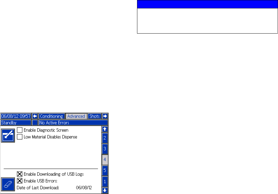
Appendix F - USB Operation
102 313997W
Appendix F - USB Operation
Overview
There are 3 main uses for the USB on a GMS™ system
• Ability to download a log of up to the past 50,000
errors, events, or jobs that can contain over 150,000
snapshots of critical dispense information.
• Ability to download, modify, and upload custom lan-
guage files
• Ability to download and upload system configura-
tions
• This data includes most user selectable and
user configurable settings.
• This data does not include pump counters, error
and event logs, shot and sequence counters
USB Options
The only options for USB on the ADM are in Advanced
Screen 4, see page 81.
The first option is a checkbox that enables or disables
the downloading of the Error Event and Shot Data log
files. The Shot Data log runs during all recirculation,
shots, and operator modes.
The second option is the Erase icon which will reset the
last download date to a time where all logs can be
downloaded. This will allow the user to download all the
USB log entries, which may take over 2 hours if the log
files are full. Currently the ADM does not monitor the
USB logs and alert the user when data may be overwrit-
ten so in order to minimize download times and the risk
of losing data it is recommended that the user download
the logs every 2 weeks or more often if the machine is
used during more than one full shift a day.
Download Log Files
If the “Enable Downloading of USB Logs” is checked,
the user can use a USB stick-drive to download the log
files.
To download the log files, insert a high-quality USB
stick-drive into the USB port in the bottom of the ADM.
The ADM will automatically begin downloading the log
files as well as the custom language file (DISP-
TEXT.TXT) and the system settings (SETTINGS.TXT).
The status of the download will be shown in the Status
bar.
NOTICE
Low-quality USB stick drives may lead to burning
out the USB port on the ADM. Use only high-quality
USB stick-drives with the ADM USB port.
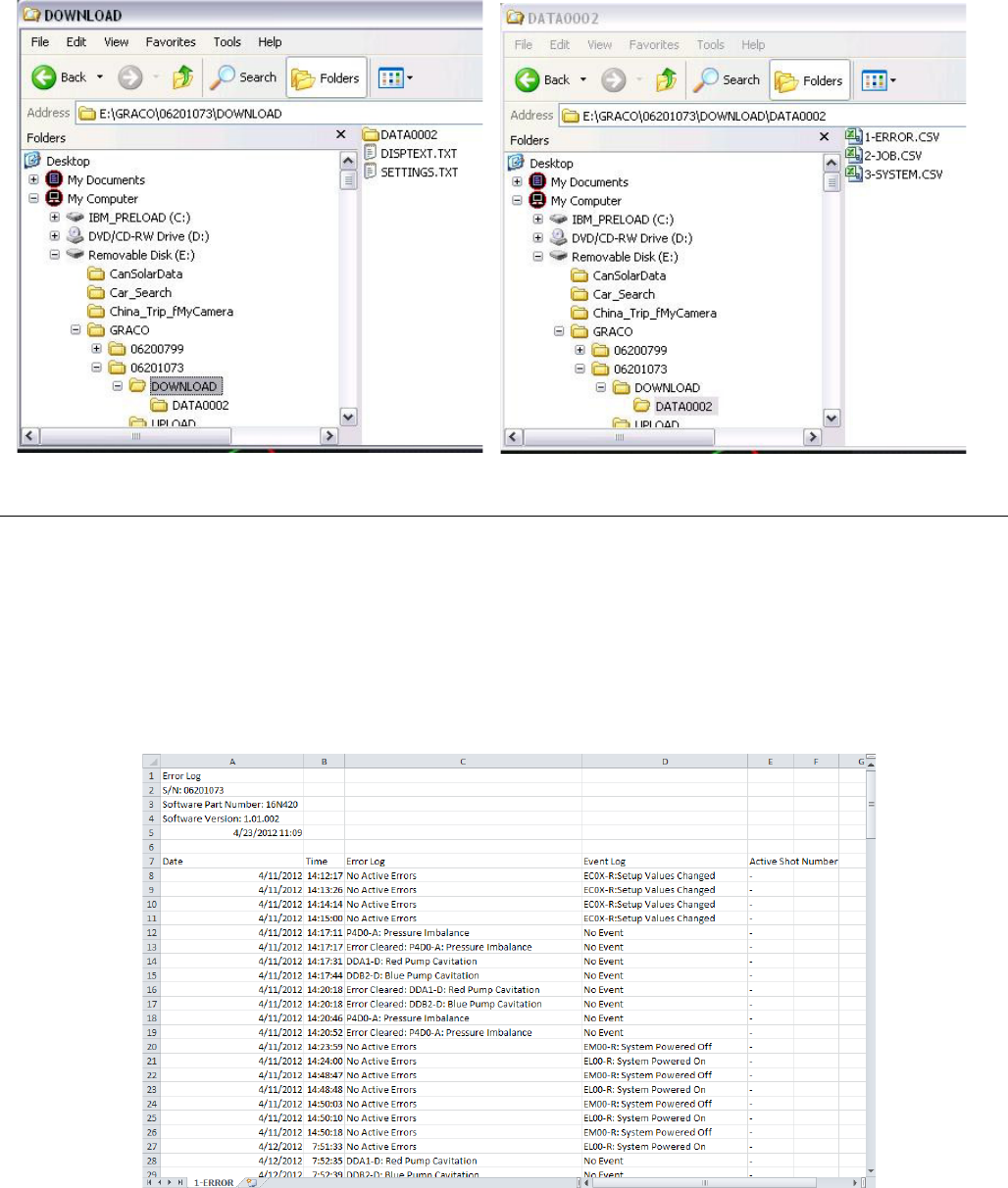
Appendix F - USB Operation
313997W 103
Log Files, Folder Structure
Each time a stick-drive is inserted into the ADM USB port, a new folder named DATAxxxx is created. The number at
the end of the folder name is incremented each time a stick-drive is inserted and data is downloaded or uploaded. In
each DATAxxxx folder there is three log files. They are formatted as .csv (comma separated value) files and can be
opened by most text editors or data processing programs such as Excel.
Example 1-ERROR File
The 1-ERROR file is the Errors and Events log file.
FIG. 24: DOWNLOAD, DATAxxxx Folders
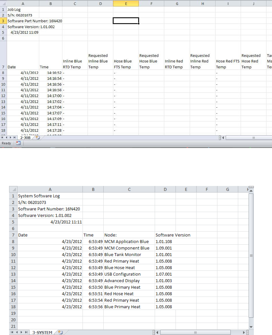
Appendix F - USB Operation
104 313997W
Example 2-JOB File
The 2-JOB file is the Shot Data Log file.
Example 3-SYSTEM File
The 3-SYSTEM file is the Software Version log file.
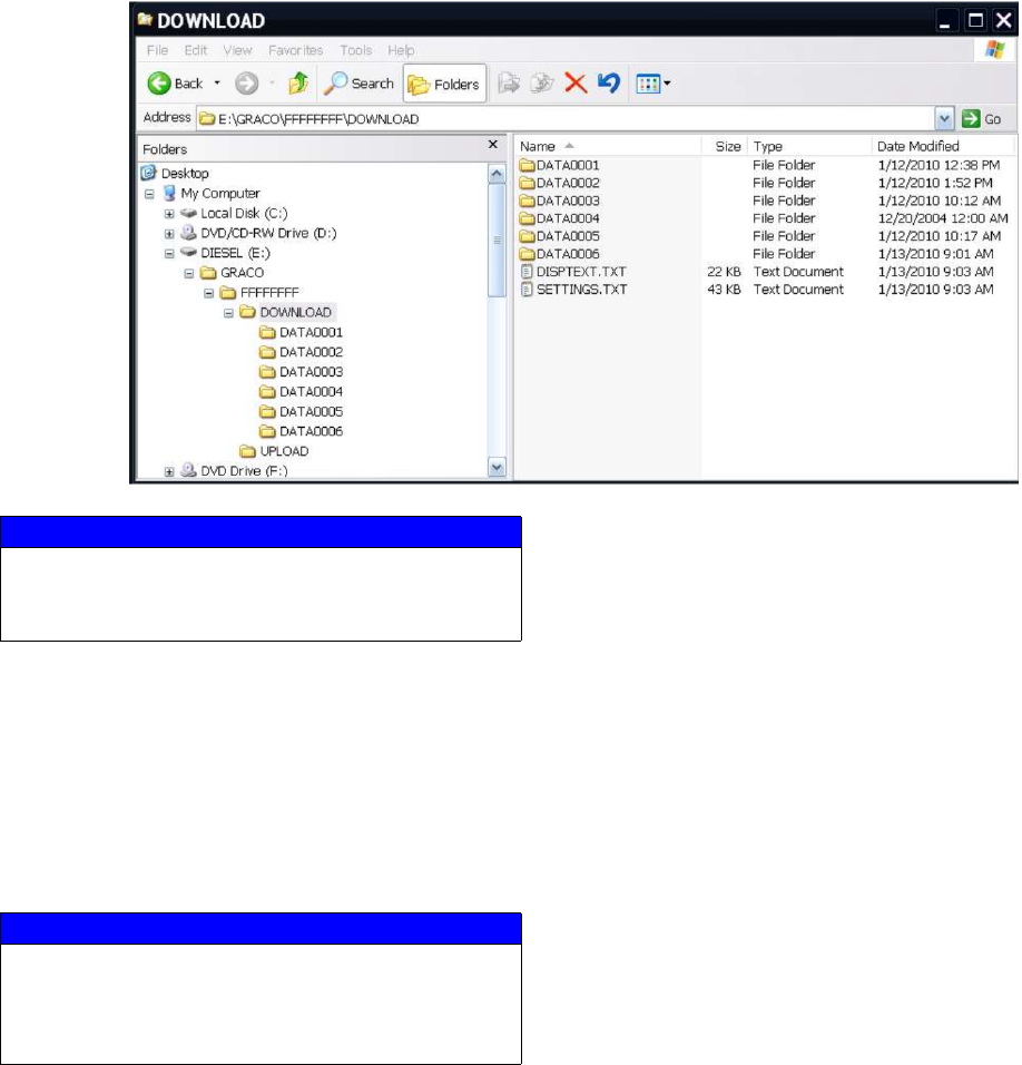
Appendix F - USB Operation
313997W 105
Transfer System Settings
Use the following process to transfer system settings
from one machine to another.
1. Insert a high-quality USB stick-drive into the USB
port on the system with the settings to be trans-
ferred. Once the download is complete the SET-
TINGS.TXT file will be located in the “DOWNLOAD”
folder.
2. Plug the USB stick-drive into a computer.
3. Navigate to the DOWNLOAD folder.
4. Copy the SETTINGS.TXT file from the DOWNLOAD
folder into the UPLOAD folder.
5. Remove the USB stick-drive from the computer and
install it into the ADM USB port for the second
machine. The software will automatically begin
updating.
NOTE: Before the update begins the ADM automatically
shuts down the system, aborting any in-progress dis-
pensing. When the software is updating the system a
pop-up box will appear to inform the user of the update
and the system will lock. Once the update is complete
the ADM will tell the user to cycle power to apply the
updates. Once this box appears it is safe to remove the
drive before cycling power.
6. When the software is done updating, remove the
USB stick-drive from the ADM USB port and install
in a computer.
7. Navigate to the UPLOAD folder and remove the
SETTINGS.TXT file.
NOTE: Immediately after uploading the settings, remove
the SETTINGS.TXT file from the UPLOAD folder to pre-
vent accidental loss of data the next time the USB
stick-drive is inserted into the ADM USB port. If there is
a SETTINGS.TXT file in the UPLOAD folder when the
USB stick-drive is inserted into the ADM USB port the
software will try to update the ADM.
NOTICE
Low-quality USB stick drives may lead to burning
out the USB port on the ADM. Use only high-quality
USB stick-drives with the ADM USB port.
NOTICE
The user should never attempt to modify the SET-
TINGS.TXT file in any way. Graco is not responsible
for damages caused by an improperly modified
setup file.

Appendix F - USB Operation
106 313997W
Update Custom Language
Use the following process to customize the text on the
ADM. The language file DISPTEXT.TXT can be modi-
fied in Excel but must be saved as a Unicode Text file
with the extension .TXT in order for it to properly import.
1. Insert a high-quality USB stick-drive into the USB
port on the system with the settings to be trans-
ferred. Once the download is complete the DISP-
TEXT.TXT file will be located in the “DOWNLOAD”
folder.
2. Plug the USB stick-drive into a computer.
3. Navigate to the DOWNLOAD folder.
4. Copy the DISPTEXT.TXT file from the DOWNLOAD
to your computer.
5. Use any data processing software such as Excel to
edit the DISPTEXT.TXT file. When done editing
save the file as the “Unicode Text” format. See
Example DISPTEXT.TXT File on page 107.
a. In the first column, locate the string to change.
b. In the second column of the same row, enter the
new string.
c. Save the file as a Unicode Text file. The name
must remain “DISPTEXT.TXT”.
6. Copy the edited DISPTEXT.TXT file into the
UPLOAD folder.
7. Remove the USB stick-drive from the computer and
install it into the ADM USB port. The software will
automatically begin updating.
NOTE: Before the update begins the ADM automatically
shuts down the system, aborting any in-progress dis-
pensing. When the software is updating the system a
pop-up box will appear to inform the user of the update
and the system will lock. Once the update is complete
the ADM will tell the user to cycle power to apply the
updates. Once this box appears it is safe to remove the
drive before cycling power.
8. When the software is done updating, remove the
USB stick-drive from the ADM USB port and install
in a computer.
9. Navigate to the UPLOAD folder and remove the
DISPTEXT.TXT file.
NOTE: Immediately following uploading the language
file, remove the DISPTEXT.TXT file from the UPLOAD
folder to prevent accidental loss of data the next time the
USB stick-drive is inserted into the ADM USB port. If
there is a DISPTEXT.TXT file in the UPLOAD folder
when the USB stick-drive is inserted into the ADM USB
port the software will try to update the ADM.
NOTICE
Low-quality USB stick drives may lead to burning
out the USB port on the ADM. Use only high-quality
USB stick-drives with the ADM USB port.
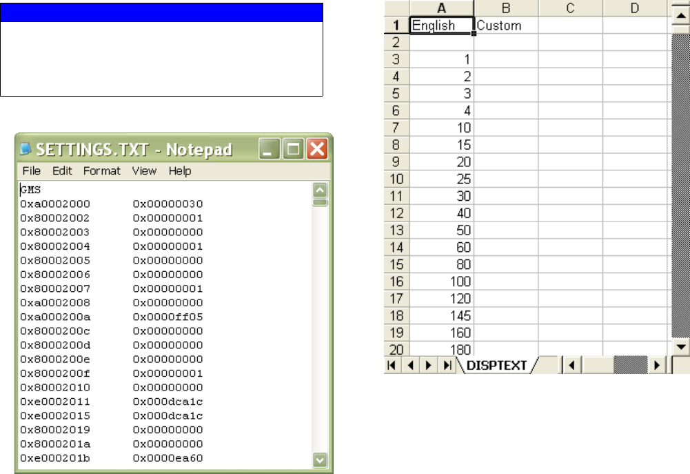
Appendix F - USB Operation
313997W 107
Example SETTINGS.TXT File Example DISPTEXT.TXT File
NOTICE
The user should never attempt to modify the SET-
TINGS.TXT file in any way. Graco is not responsible
for damages caused by an improperly modified
setup file.
Technical Data
108 313997W
Technical Data
All other brand names or marks are used for identification purposes and are trademarks of their respective owners.
Maximum Fluid Working Pressure. . . 3000 psi (20.7 MPa, 207 bar)
Maximum Fluid Temperature . . . . . . . 190°F (88°C)
Fluid Inlet Feed Pressure Range . . . . 50 psi (0.35 MPa, 3.5 bar) to 250 psi (1.75 MPa, 17.5 bar)
Fluid Inlets . . . . . . . . . . . . . . . . . . . . . Component A (Red): 1/2 npt(f)
Component B (Blue): 3/4 npt(f)
Fluid Outlets. . . . . . . . . . . . . . . . . . . . Component A (Red): #8 (1/2 in.) JIC (3/4-16 unf), with #5 (5/16 in.) JIC adapter
Component B (Blue): #10 (5/8 in.) JIC (7/8-14 unf), with #6 (3/8 in.) JIC adapter
Fluid Circulation Ports . . . . . . . . . . . . 1/4 npsm(m), with plastic tubing, 250 psi (1.75 MPa, 17.5 bar) maximum
Line Voltage Requirement . . . . . . . . . 230V / 1 phase and 230V / 3 phase Models: 195-264V, 50/60 Hz
400V / 3 phase: 360-440V, 50/60 Hz; see 400 V Power Requirements, page 4
Amperage Requirement. . . . . . . . . . . See Models on page 4
Sound Power . . . . . . . . . . . . . . . . . . . 93 dB
Heater Power
(A (Red) and B (Blue) heaters total,
no hose, Heated HFR Models only). . 12 kW
Hydraulic reservoir capacity. . . . . . . . 9 gal. (34 liters)
Recommended hydraulic fluid . . . . . . Citgo A/W Hydraulic Oil, ISO Grade 46
Weight . . . . . . . . . . . . . . . . . . . . . . . . Units with 12 kW Heaters: 868 lb (394 kg)
Units without heaters: 634 lb (288 kg)
Wetted Parts . . . . . . . . . . . . . . . . . . . Aluminum, stainless steel, zinc-plated carbon steel, brass, carbide, chrome,
fluoroelastomer, PTFE, ultra-high molecular weight polyethylene, chemically
resistant o-rings
Motor Control Module Technical Data
313997W 109
Motor Control Module Technical Data
Overtemperature protection is provided to protect from motor overload.
Current limit, set via the software, is provided as a secondary protection from motor overload.
All installations and wiring must comply with NEC and local electrical codes.
Input Specifications
Input Line Voltage . . . . . . . . . . . . . . . . . . . . . . . . . . . 0-264 Vac, line-to-line
Input Line Phasing . . . . . . . . . . . . . . . . . . . . . . . . . . . Single or Three Phase
Input Line Frequency . . . . . . . . . . . . . . . . . . . . . . . . . 50/60 Hz
Input Current per Phase. . . . . . . . . . . . . . . . . . . . . . . 25A (three-phase), 50A (single-phase)
Maximum Branch Circuit Protection Rating: . . . . . . . 30A (three-phase), 63A (single-phase)
Short Circuit Current Rating. . . . . . . . . . . . . . . . . . . . 5 kA
Output Specifications
Output Line Voltage . . . . . . . . . . . . . . . . . . . . . . . . . . 0-264 Vac
Output Line Phasing . . . . . . . . . . . . . . . . . . . . . . . . . Three Phase
Output Current . . . . . . . . . . . . . . . . . . . . . . . . . . . . . . 0-30A
Output Overload. . . . . . . . . . . . . . . . . . . . . . . . . . . . . 200% for 0.2 seconds
DC Power Supply . . . . . . . . . . . . . . . . . . . . . . . . . . . . . . . 24 Vdc, Class 2, Graco-provided power supply
Enclosure . . . . . . . . . . . . . . . . . . . . . . . . . . . . . . . . . . . . . Type 1
Max Ambient Temperature . . . . . . . . . . . . . . . . . . . . . . . . 50°C (122°F)
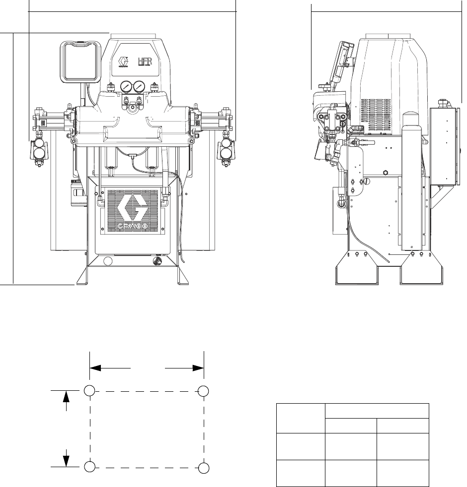
Motor Control Module Technical Data
110 313997W
Dimensions
Bolt Mounting Pattern and
Dimensions
Ref
Type of Base
No Pallet Pallet
D24 in.
(610 mm)
32.4 in.
(823 mm)
E15 in.
(381 mm)
30.3 in.
(770 mm)
Front
Right
D
E
59.8 in.
(1520 mm)
47.5 in.
(1210 mm)
34.1 in.
(870 mm)

Motor Control Module Technical Data
313997W 111

All written and visual data contained in this document reflects the latest product information available at the time of publication.
Graco reserves the right to make changes at any time without notice.
For patent information, see www.graco.com/patents.
Original instructions. This manual contains English. MM 313997
Graco Headquarters: Minneapolis
International Offices: Belgium, China, Japan, Korea
GRACO INC. AND SUBSIDIARIES • P.O. BOX 1441 • MINNEAPOLIS MN 55440-1441 • USA
Copyright 2010, Graco Inc. All Graco manufacturing locations are registered to ISO 9001.
www.graco.com
Revised September 2014
Graco Standard Warranty
Graco warrants all equipment referenced in this document which is manufactured by Graco and bearing its name to be free from defects in
material and workmanship on the date of sale to the original purchaser for use. With the exception of any special, extended, or limited warranty
published by Graco, Graco will, for a period of twelve months from the date of sale, repair or replace any part of the equipment determined by
Graco to be defective. This warranty applies only when the equipment is installed, operated and maintained in accordance with Graco’s written
recommendations.
This warranty does not cover, and Graco shall not be liable for general wear and tear, or any malfunction, damage or wear caused by faulty
installation, misapplication, abrasion, corrosion, inadequate or improper maintenance, negligence, accident, tampering, or substitution of
non-Graco component parts. Nor shall Graco be liable for malfunction, damage or wear caused by the incompatibility of Graco equipment with
structures, accessories, equipment or materials not supplied by Graco, or the improper design, manufacture, installation, operation or
maintenance of structures, accessories, equipment or materials not supplied by Graco.
This warranty is conditioned upon the prepaid return of the equipment claimed to be defective to an authorized Graco distributor for verification of
the claimed defect. If the claimed defect is verified, Graco will repair or replace free of charge any defective parts. The equipment will be returned
to the original purchaser transportation prepaid. If inspection of the equipment does not disclose any defect in material or workmanship, repairs will
be made at a reasonable charge, which charges may include the costs of parts, labor, and transportation.
THIS WARRANTY IS EXCLUSIVE, AND IS IN LIEU OF ANY OTHER WARRANTIES, EXPRESS OR IMPLIED, INCLUDING BUT NOT LIMITED
TO WARRANTY OF MERCHANTABILITY OR WARRANTY OF FITNESS FOR A PARTICULAR PURPOSE.
Graco’s sole obligation and buyer’s sole remedy for any breach of warranty shall be as set forth above. The buyer agrees that no other remedy
(including, but not limited to, incidental or consequential damages for lost profits, lost sales, injury to person or property, or any other incidental or
consequential loss) shall be available. Any action for breach of warranty must be brought within two (2) years of the date of sale.
GRACO MAKES NO WARRANTY, AND DISCLAIMS ALL IMPLIED WARRANTIES OF MERCHANTABILITY AND FITNESS FOR A
PARTICULAR PURPOSE, IN CONNECTION WITH ACCESSORIES, EQUIPMENT, MATERIALS OR COMPONENTS SOLD BUT NOT
MANUFACTURED BY GRACO. These items sold, but not manufactured by Graco (such as electric motors, switches, hose, etc.), are subject to
the warranty, if any, of their manufacturer. Graco will provide purchaser with reasonable assistance in making any claim for breach of these
warranties.
In no event will Graco be liable for indirect, incidental, special or consequential damages resulting from Graco supplying equipment hereunder, or
the furnishing, performance, or use of any products or other goods sold hereto, whether due to a breach of contract, breach of warranty, the
negligence of Graco, or otherwise.
FOR GRACO CANADA CUSTOMERS
The Parties acknowledge that they have required that the present document, as well as all documents, notices and legal proceedings entered into,
given or instituted pursuant hereto or relating directly or indirectly hereto, be drawn up in English. Les parties reconnaissent avoir convenu que la
rédaction du présente document sera en Anglais, ainsi que tous documents, avis et procédures judiciaires exécutés, donnés ou intentés, à la suite
de ou en rapport, directement ou indirectement, avec les procédures concernées.
Graco Information
For the latest information about Graco products, visit www.graco.com.
TO PLACE AN ORDER, contact your Graco distributor or call to identify the nearest distributor.
Phone: 612-623-6921 or Toll Free: 1-800-328-0211 Fax: 612-378-3505
