Graco 332518C Dyna Star Hp Or Hf Pump Auto Fill Shut Off Kit Users Manual Kit, Instructions, English
2015-04-02
: Graco Graco-332518C-Dyna-Star-Hp-Or-Hf-Pump-Auto-Fill-Shut-Off-Kit-Users-Manual-685750 graco-332518c-dyna-star-hp-or-hf-pump-auto-fill-shut-off-kit-users-manual-685750 graco pdf
Open the PDF directly: View PDF ![]() .
.
Page Count: 14
332518C
Instructions
Dyna-Star® HP and HF Pump
Auto-Fill® Shut Off Kit
Used with Dyna-Star HP or HF Pump to fill Graco Tank/Reservoir. For automatic grease
lubrication systems only. Cannot be used with pumps equipped with a dip stick, low level
indicator or follower plate. For professional use only.
5000 psi (34.47 MPa, 344 bar) Maximum Lubricant Inlet Pressure
3/8 inch npt inlet and outlet
Maximum Flow: 2 gpm (7.57 lpm)
Model: 77X521
Important Safety Instructions
Read all warnings and instructions in this man-
ual and the Dyna-Star HP and HF Pump instruc-
tion manual. Save all instructions.
EN
Warnings
2332518C
Warnings
The following warnings are for the setup, use, grounding, maintenance, and repair of this equipment. The exclama-
tion point symbol alerts you to a general warning and the hazard symbols refer to procedure-specific risks. When
these symbols appear in the body of this manual or on warning labels, refer back to these Warnings. Product-specific
hazard symbols and warnings not covered in this section may appear throughout the body of this manual where
applicable.
+
SKIN INJECTION HAZARD
High-pressure fluid from dispensing device, hose leaks, or ruptured components will pierce skin. This
may look like just a cut, but it is a serious injury that can result in amputation. Get immediate surgical
treatment.
• Do not point dispensing device at anyone or at any part of the body.
• Do not put your hand over the fluid outlet.
• Do not stop or deflect leaks with your hand, body, glove, or rag.
• Follow the Pressure Relief Procedure when you stop dispensing and before cleaning, checking, or
servicing equipment.
• Tighten all fluid connections before operating the equipment.
• Check hoses and couplings daily. Replace worn or damaged parts immediately.
EQUIPMENT MISUSE HAZARD
Misuse can cause death or serious injury.
• Do not operate the unit when fatigued or under the influence of drugs or alcohol.
• Do not exceed the maximum working pressure or temperature rating of the lowest rated system
component. See Technical Data in all equipment manuals.
• Use fluids and solvents that are compatible with equipment wetted parts. See Technical Data in all
equipment manuals. Read fluid and solvent manufacturer’s warnings. For complete information
about your material, request MSDS from distributor or retailer.
• Turn off all equipment and follow the Pressure Relief Procedure when equipment is not in use.
• Check equipment daily. Repair or replace worn or damaged parts immediately with genuine manu-
facturer’s replacement parts only.
• Do not alter or modify equipment. Alterations or modifications may void agency approvals and create
safety hazards.
• Make sure all equipment is rated and approved for the environment in which you are using it.
• Use equipment only for its intended purpose. Call your distributor for information.
• Route hoses and cables away from traffic areas, sharp edges, moving parts, and hot surfaces.
• Do not kink or over bend hoses or use hoses to pull equipment.
• Keep children and animals away from work area.
• Comply with all applicable safety regulations.
PERSONAL PROTECTIVE EQUIPMENT
Wear appropriate protective equipment when in the work area to help prevent serious injury, including
eye injury, hearing loss, inhalation of toxic fumes, and burns. This protective equipment includes but is
not limited to:
• Protective eyewear, and hearing protection.
• Respirators, protective clothing, and gloves as recommended by the fluid and solvent manufacturers.
WARNINGWARNINGWARNING
WARNING
Auto-Fill Shut Off Overview
332518C 3
Auto-Fill Shut Off
Overview
Reference letters used in the following instructions refer
to Parts Table and Drawing shown on the cover of this
manual.
The Auto-Fill Shut Off is used for refilling the grease
tank/reservoir in an automatic lubrication system. As
grease is added to the reservoir, it pushes the dia-
phragm up to the top of the reservoir. The diaphragm
then pushes the valve pin and closes the inlet fluid path.
Pressure Relief
Follow the Pressure Relief Procedure whenever
you see this symbol.
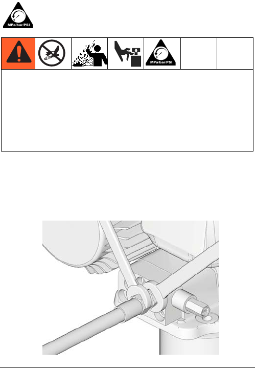
To relieve pressure in the system, use two wrenches
working in opposite directions on pump outlet fitting to
slowly loosen fitting only until fitting is loose and no
more lubricant or air is leaking from fitting. See FIG. 1.
This equipment stays pressurized until pressure is
manually relieved. To help prevent serious injury from
pressurized fluid, such as skin injection, splashing
fluid and moving parts, follow the Pressure Relief
Procedure when you stop dispensing and before
cleaning, checking, or servicing the equipment.
FIG. 1
Installation
4332518C
Installation
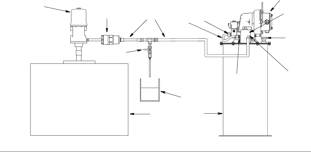
Typical Installation
A Dyna-Star Pump
B Breather
C Auto-Fill Inlet
D Auto-Fill Outlet
E Pump Manifold / Vent Valve Inlet
F Reservoir
G Pressure Relief Valve (Required, user supplied)
H Fluid Overflow Container
J Remote Filling Station Reservoir
K Remote Filling Station Pump (pneumatic)
L Lubricant Supply Hose (Required, user supplied)
M Filter (recommended if grease/environment is
contaminated)
1 Auto-Fill Shut Off
3 Tube (vent valve)
4 Tube (manifold)
FIG. 2
1
C
3 / 4
B
F
G
H
K
J
D
E
L
A
M
Installation
332518C 5
Disassembly
NOTE:
• Reference numbers used in the following instruc-
tions refer to Kit Parts provided on the cover of this
manual.
• Upper case letters used in the following instructions
refer to Typical Installation provided on page 4.
• Lower case letters used in the following instructions
refer to component parts or user provided parts not
included in the Kit.
• Steps 1 - 2 only apply to pumps that have already
been in service and are adding an Auto-Fill Shut Off
Valve. For new installations, begin instructions with
Step 3.
1. Disconnect Dyna-Star pump (A) from main power
source.
2. Relieve pressure (see Pressure Relief procedure,
page 3).
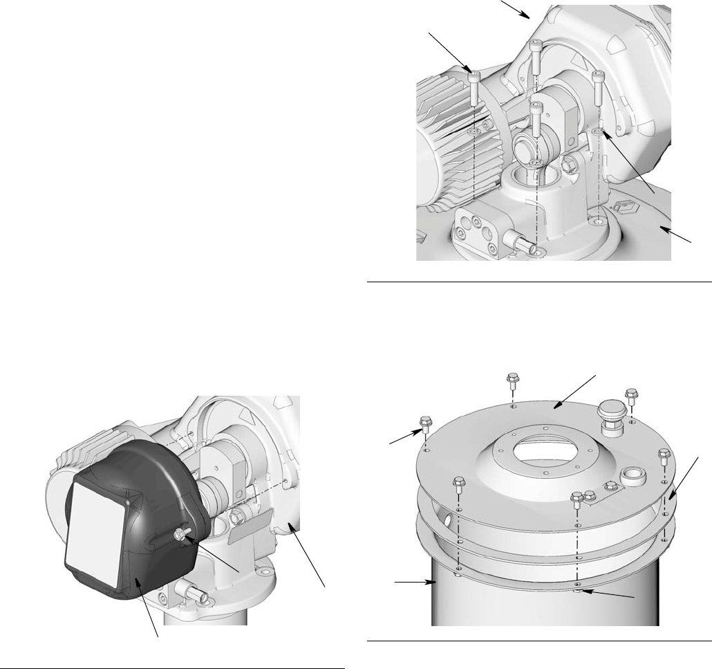
3. Loosen bolts (a) and remove cover (b) from
Dyna-Star pump (A) (FIG. 3). Save these parts to
use for installation.
4. Remove screws (c) and washers (d) holding
Dyna-Star Pump (A) to cover (e) and remove pump
from cover (FIG. 4). Save these parts to use for
installation.
5. Remove the bolts (g) and nuts (gg) (holding the
cover (e) to the reservoir (F) (FIG. 5). Save these
parts to use for installation.
6. Remove cover (e) and gasket (j) (FIG. 5). Save these
parts to use for installation.
7. (If previously installed) remove follower plate
and / or low level indicator or dipstick. Discard these
parts according to applicable guidelines.
FIG. 3
b
a
A
FIG. 4
FIG. 5
c
d
A
e
g
e
F
j
gg
Installation
6332518C
Reassembly
NOTE:
• Reference numbers used in the following instruc-
tions refer to Kit Parts provided on the cover of this
manual.
• Upper case letters used in the following instructions
refer to Typical Installation provided on page 4.
• Lower case letters used in the following instructions
refer to component parts or user provided parts not
included in the Kit.
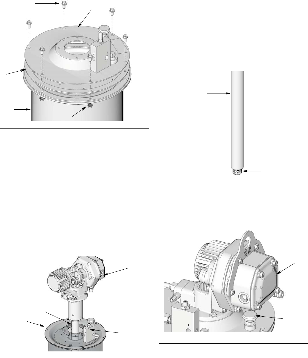
1. Align diaphragm (2) on reservoir (F) (FIG. 6), match-
ing holes around the rim of diaphragm with the
holes in the top of the reservoir. Refer to FIG. 6 to
determine the correct orientation of the diaphragm.
NOTE: The diaphragm (2) has six valves (not pic-
tured). When the diaphragm is correctly installed,
valves will face downward.
2. Install gasket (j) removed in step 6, page 5 over the
diaphragm (2) (FIG. 6), matching holes in gasket
with the holes in rim of diaphragm.
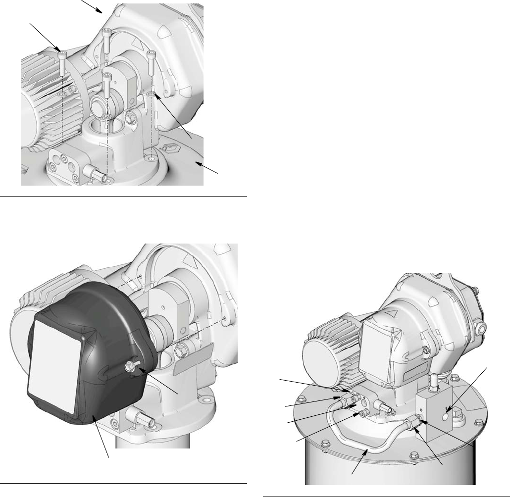
3. Remove screws (k) and nuts (kk) from accessory
cover plate (l) [installed on the pump reservoir cover
(e)] (FIG. 7). Remove plate and gasket (m). Discard
screws, nuts, plate and gasket, you will not use
them again.
4. Align gasket (7) with holes (n) in cover (e) (FIG. 8).
5. Install Auto-Fill Shut Off Valve (1) over gasket (7).
Install bolts (6) through holes (n). Tighten bolts
securely. See FIG. 8.
FIG. 6
2
j
F
FIG. 7
FIG. 8
e
l
k
m
kk
1
6
n
e
7
Installation
332518C 7
6. Install cover (e) over gasket (j) on reservoir (F) (FIG.
9).
7. Securely fasten cover (e) in place on top of reservoir
(F) using bolts (g) and nuts (gg) removed in Step 5,
page 5.
HINT: To ensure the cover is tightened correctly,
turn nuts (gg) until it is snug to reservoir. Then turn it
one more half turn.
NOTE: Do not over tighten cover (e) to reservoir (F).
Over tightening could crush the gasket (j) between the
cover and reservoir; pushing the gasket out of place and
breaking the seal.
8. Install pump down-tube (p) through opening in the
center of the cover (e) and hole in the center of the
diaphragm (2) as shown in FIG. 10.
NOTE: The pump down tube has two parts (FIG. 11):
• Fill tube (outer): directs grease to the bottom of
the pump during the fill operation. As grease is
filled into the reservoir, the diaphragm moves
up. When the grease level in the reservoir has
reached full, the diaphragm pushes the valve
pin up, closing off fluid path, ending the fill oper-
ation.
• Pump tube (inside): when pump is operating,
grease is drawn out of the bottom of the pump
reservoir, through the pump tube and dispensed
to the lubrication points.
NOTE: When the pump (A) is correctly installed, the
breather (B) will be below the control box (r) as shown in
FIG. 12.
FIG. 9
FIG. 10
e
g
j
F
gg
2
1
A
p
FIG. 11
FIG. 12
Fill
Tube
Pump
Tube
B
r
Installation
8332518C
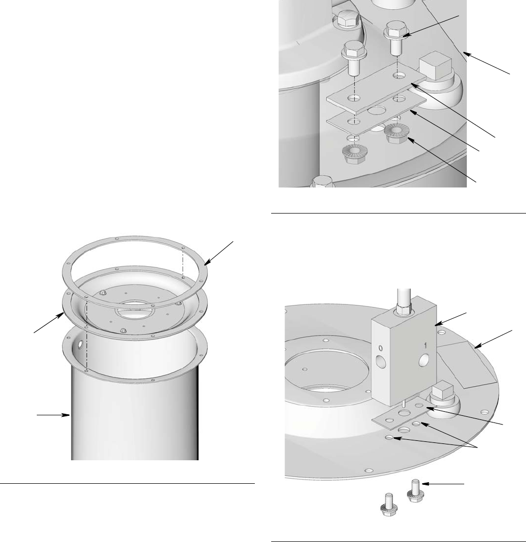
9. Securely fasten pump (A) to cover (e) using screws
(c) and washers (d). Use a wrench to tightened
securely.
10. Reinstall cover (b) using bolts (a). Use a wrench to
tighten bolts securely.
11. The Auto-Fill Shutoff Kit includes two supply
hoses/tubes (3 or 4 as shown on the cover.) Only
one hose/tube is used. Discard the hose/tube you
do not use.
• Supply tube (4) (marked with the 16V750 alumi-
num tag) and two connector fittings (5) are used
for manifold assemblies. Supply tube (3) can be
discarded. It is not used for a manifold installa-
tion.
a. Install connector fittings (5) to manifold inlet
(E) and Auto-Fill Shut Off outlet (D). Wrench
tighten each fitting (5) securely.
b. Install end of supply tube (4) to manifold inlet
(E) first and then install the other end of the
supply tube to the Auto-Fill Shut Off outlet (D)
and as shown in FIG. 15.
HINT: For easier installation, loosen (but do not entirely
remove) screws (G) securing manifold (F) to pump. This
will allow the manifold to remain in a loosely mounted
state while installing the supply tube (4). After tube has
been installed securely, re-tighten manifold screws (G)
to secure manifold (F) to pump.
FIG. 13
FIG. 14
c
d
A
e
b
a
FIG. 15
5
4
C
E
5
D
F
G

Installation
332518C 9
• Supply tube (3) (marked with the 16X381 alumi-
num tag) and two connector fittings (5), are
used for vent valve assemblies. Supply tube (4)
can be discarded. It is not used for a vent valve
installation.
a. Install connector fitting (5) to Auto-Fill Shut
Off outlet (D) and Vent Valve inlet (E).
b. Install end of supply tube (3) to Vent Valve
inlet (E) first. Then install the other end of the
supply tube to the Auto-Fill Shut Off outlet (D)
as shown in FIG. 16.
HINT: For easier installation, loosen (but do not entirely
remove) screws (G) securing vent valve (F) to pump.
This will allow the vent valve to remain in a loosely
mounted state while installing the supply tube (3). After
tube has been installed securely, re-tighten vent valve
screws (G) to secure vent valve (F) to pump.
12. Install a (user supplied) lubricant supply hose (L)
between Auto-Fill Shut Off inlet (C) (FIG. 15 or FIG.
16) and the remote filling station pump (K).
13. A pressure relief valve (G) and overflow container
(H) (for collecting excess fluid that drains during
pressure relief) must be installed in an easily acces-
sible location between the remote filling station
pump (K) and the Auto-Fill Shut Off (1). This pres-
sure relief valve is used to relieve pressure in the
refill line and to reset the Auto-Fill Shut Off. See Typ-
ical Installation, page 4.
NOTE:
• Operator must monitor system while filling tank
to prevent accidental fluid overflow.
• A Pressure Relief Kit: 247902 is available from
Graco. Contact your distributor or Graco Cus-
tomer Service for additional information about
this kit.
• In some setups the pressure relief valve (G) can
be installed directly to the Auto-Fill Shut Off (1)
as shown in FIG. 17.
FIG. 16
3
C
E
5
D
5
F
G
FIG. 17
COMPONENT RUPTURE HAZARD
The maximum working pressure of each component
in the system may not be the same. To reduce the
risk of overpressurizing any component in the
system, be sure you know the maximum working
pressure of each component. Never exceed the
maximum working pressure of the lowest rated
component in the system. Overpressurizing any
component can result in rupture and/or property
damage and serious injury.
Regulate pressure to the pump so that no fluid line,
component or accessory is over pressurized.
G
1

Installation
10 332518C
14. Turn on remote filling station pump (K) and fill reser-
voir (F) until the indicator pin on the Auto-Fill Valve
(1) pushes up as shown in FIG. 18; pressure in the
refill pump (K) builds and the pump stalls.
15. Turn off air supply to refill pump (K).
16. Relieve remote filling station pump pressure using
the following Remote Filling Station Pressure Relief
procedure:
Remote Filling Station Pressure Relief
The following Pressure Relief Procedure is only
used with the Auto-Fill Shut Off Valve to relieve
remote filling station and lubricant supply line
pressure.
a. To relieve pressure between the refill pump and
Auto-Fill Shut Off, open ball valve (bv) (FIG. 19).
Pressure will be released and excess fluid will
drain out of the drain tube (dt) and into the lubri-
cation collection container (H).
b. Close ball valve (bv) when all pressure has
been relieved.
NOTE: The pin may not drop and the Auto-Fill
may not reset because the tank is full. However,
when the pump begins using the grease, the pin
resets. The pin must reset before the next cycle
of refilling.
17. Disconnect lubrication supply hose (L) from Auto-Fill
(1).
18. Install plug in Auto-Fill inlet or supply hose (L) inlet
to prevent contaminants from entering the pump.
FIG. 18
This equipment stays pressurized until pressure is
manually relieved. To help prevent serious injury from
pressurized fluid, such as skin injection, splashing
fluid and moving parts, follow the Pressure Relief
Procedure when you stop dispensing and before
cleaning, checking, or servicing the equipment.
pin
up
1
FIG. 19: In line installation shown
FIG. 20
bv
G
dt
H
pin
drops
Installation
332518C 11
Troubleshooting
Problem Cause Solution
Refilling pump, stalls. Pressurized
tank is not refilling.
Auto-Fill Shut Off Valve is in closed
condition and has not reset
1. Disconnect refilling line.
2. Relieve all line pressure using
the Remote Filling Station Pres-
sure Relief procedure provided
on page 10.
Make sure valve pin is down. See
Remote Filling Station Pressure
Relief procedure, Step b, page 10.
Parts
12 332518C
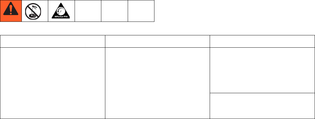
Parts
Model 77X521 (FIG. 21)
*Prior to installation, apply thread sealant or PTFE Tape
to all npt tapered pipe threads.
Accessories
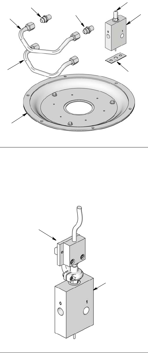
Remote Electric Signaling (FIG. 22)
Remote electric signaling can be added to the Auto-Fill
Shut Off. Contact your Graco distributor or Graco Cus-
tomer service for assistance when ordering these parts.
Filter Assembly (see M, page 4)
Pressure Relief Assembly (see G, page 4)
Ref Part No. Description Qty
1 16V582 VALVE, auto shut off 1
2 16V748 DIAPHRAGM, assembly 1
3 16X381 TUBE, vent valve 1
4 16V750 TUBE, manifold 1
5 121311 FITTING, connector, 3/8 in. npt*
x JIC
2
6 16X389 BOLT, M8 x 1.25 x 2 mm (not
shown)
2
7 16V396 SEAL, auto shutoff valve 1
8 404157 CAP 1
FIG. 21
4
3
2
5
51
8
7
Ref Part No. Description
9563272 SWITCH, cycle
563273 SWITCH, submersible
Part No. Description
77X523 FILTER
Part No. Description
247902 PRESSURE RELIEF
FIG. 22
9
1

Technical Data
332518C 13
Technical Data
.
Dimensions
Auto-Fill Shutoff Valve for Dyna-Star HP or HF Pump
US Metric
Maximum working pressure 5000 psi 34.4 MPa, 344 bar
Inlet/Outlet Sizes
Outlet (marked “0”) 3/8 in. npt(f)
Inlet (refill - marked “1”) 3/8 in. npt(f)
Maximum flow 2 gpm 7.6 lpm
Wetted Parts
Valve neoprene rubber, zinc plated parts, stainless steel, chrome plated parts,
plastic acetal
Seal fluorocarbon
Temperature
Working temperature -13° F to +122°F -25°C to +50°C
1.13 in.
2.75 in.
5.0 in.
12.7 cm
6.9 cm
2.8 cm
All written and visual data contained in this document reflects the latest product information available at the time of publication.
Graco reserves the right to make changes at any time without notice.
For patent information, see www.graco.com/patents.
Original instructions. This manual contains English. MM 332518
Graco Headquarters: Minneapolis
International Offices: Belgium, China, Japan, Korea
GRACO INC. AND SUBSIDIARIES • P.O. BOX 1441 • MINNEAPOLIS MN 55440-1441 • USA
Copyright 2013, Graco Inc. All Graco manufacturing locations are registered to ISO 9001.
www.graco.com
February 2014
Graco Information
To place an order, contact your Graco distributor or to identify the nearest distributor call,
Toll Free: 1-800-533-9655, Fax: 612-378-3590
