Graco 332564B Promix Pd2K Proportioner Users Manual 332564B, For Automatic Spray Applications, Operation, English
2015-04-02
: Graco Graco-332564B-Promix-Pd2K-Proportioner-Users-Manual-685991 graco-332564b-promix-pd2k-proportioner-users-manual-685991 graco pdf
Open the PDF directly: View PDF ![]() .
.
Page Count: 104 [warning: Documents this large are best viewed by clicking the View PDF Link!]
- toc
- Contents
- Related Manuals
- Models
- Warnings
- Important Isocyanate (ISO) Information
- General Information
- Advanced Display Module (ADM)
- Pre-Operation Tasks
- Pressure Relief Procedure
- Operation Using Automatic Display Module (ADM)
- Operation Using a Programmable Logic Controller (PLC)
- Run Mode Screens
- Setup Mode Screens
- Calibration Checks
- Color Change
- System Errors
- Maintenance
- Technical Data
- Graco Standard Warranty
- Contents
- tables
Operation
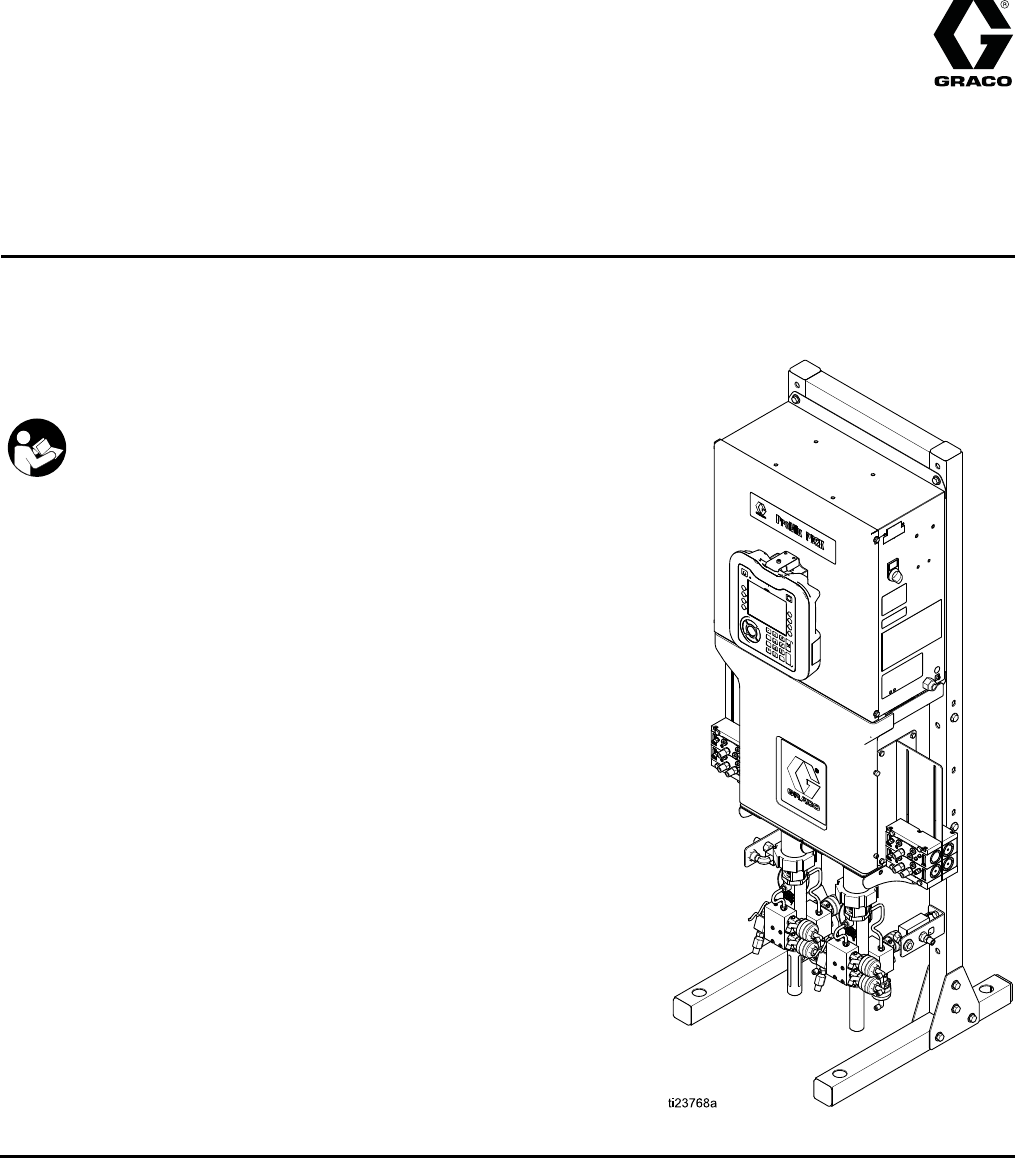
ProMix® PD2K Proportioner for
Automatic Spray Applications 332564B
EN
Electronic positive displacement proportioner for fast-setting two-component materials. Automatic
system with Advanced Display Module. For professional use only.
Important Safety Instructions
Read all warnings and instructions in this manual and in your
installation, repair, and associated component manuals.
Save these instructions.
See page 3 for model part numbers and
approvals information.
PROVEN QUALITY. LEADING TECHNOLOGY.
Contents
Related Manuals ..................................................3
Models................................................................. 4
Warnings ............................................................. 6
Important Isocyanate (ISO) Information .................. 9
General Information ............................................ 10
Advanced Display Module (ADM) ........................ 11
ADM Display................................................ 11
USB Download Procedure............................ 11
USB Upload Procedure ................................ 12
ADM Keys and Indicators ............................. 13
Soft Key Icons ............................................. 14
Navigating the Screens ................................ 16
Screen Icons ............................................... 16
Pre-Operation Tasks........................................... 17
Pre-operation Checklist ................................ 17
Power On .................................................... 17
Initial System Setup ..................................... 18
Flush Before Using Equipment...................... 18
Valve Settings.............................................. 18
Pressure Relief Procedure .................................. 19
Without Color Change .................................. 19
With Color Change....................................... 19
Operation Using Automatic Display Module
(ADM)................................................... 20
Prime and Fill the System............................. 20
Spraying...................................................... 21
Purging ....................................................... 22
Shutdown .................................................... 23
Operation Using a Programmable Logic
Controller (PLC) .................................... 24
Network Communications and Discrete
I/O ................................................. 24
Discrete I/O ................................................. 24
Communication Gateway Module (CGM)
Details ........................................... 27
Network Communication I/O Data Map ........... 28
Operation Flow Charts ................................. 42
Network Communication - Dynamic
Command Structure (DCS) ............. 47
Flow Control System .................................... 57
Run Mode Screens ............................................. 58
Opening Screen........................................... 58
Home Screen .............................................. 58
Spray Screen............................................... 62
Fill Screen ................................................... 63
Usage Screen.............................................. 64
Jobs Screen ................................................ 65
Errors Screen .............................................. 65
Events Screen ............................................. 65
Setup Mode Screens .......................................... 66
Password Screen......................................... 66
System Screen 1 ......................................... 67
System Screen 2 ......................................... 68
System Screen 3 ......................................... 69
System Screen 4 ......................................... 70
System Screen 5 ......................................... 71
Recipe Screen ............................................. 72
Flush Screen ............................................... 73
Pump Screen 1............................................ 74
Pump Screen 2............................................ 75
Pump Screen 3............................................ 76
Pressure Alarm and Deviation Limits............. 76
Calibration Screens...................................... 77
Maintenance Screens................................... 80
Advanced Screen 1...................................... 82
Advanced Screen 2...................................... 83
Advanced Screen 3...................................... 83
Calibration Checks.............................................. 84
Pump Pressure Check ................................. 84
Pump Volume Check.................................... 85
Solvent Meter Calibration ............................. 86
Color Change .....................................................87
Single Color Systems ................................... 87
Multiple Color Systems................................. 87
System Errors ....................................................88
To Clear Error and Restart............................ 88
Gun Trigger Input Function ........................... 88
Error Codes................................................. 89
Maintenance .................................................... 102
Preventive Maintenance Schedule .............. 102
Flushing .................................................... 102
Cleaning the ADM...................................... 102
Technical Data ................................................. 103
Graco Standard Warranty.................................. 104
2332564B

Related Manuals
Related Manuals
Current manuals are available at www.graco.com.
Manual No. Description
332709 ProMix PD2K Proportioner for
Automatic Spray Applications,
Repair-Parts
332458 ProMix PD2K Proportioner for
Automatic Spray Applications,
Installation
332339 Dosing Pumps, Instructions/Parts
332454 Color/Catalyst Dispense Valves,
Instructions/Parts
Manual No. Description
332455 Color Change Kits, Instructions-
Parts
333282 Color Change and Remote Mix
Manifold Kits, Instructions-Parts
332456 Pump Expansion Kits,
Instructions-Parts
332564B 3
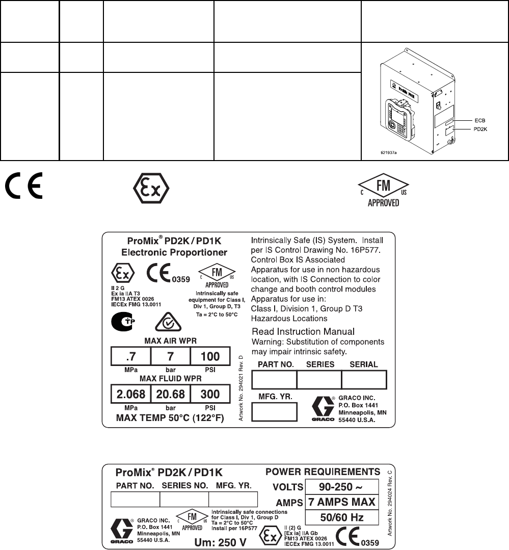
Models
Models
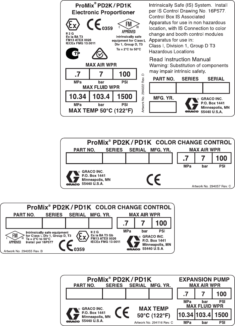
See Figs. 1–6 for component identification labels, including approval information and certification.
Part No. Series Maximum Air Working
Pressure
Maximum Fluid Working
Pressure
Location of PD2K and
Electrical Control Box
(ECB) Labels
AC1000 A100 psi (0.7 MPa,
7.0 bar)
300 psi (2.068 MPa, 20.68 bar)
AC2000 A100 psi (0.7 MPa,
7.0 bar)
1500 psi (10.34 MPa,
103.4 bar)
0359 II 2 G
Figure 1 Model AC1000 (Low Pressure) Identification
Label
Figure 2 24M672 Control Box Identification Label
Continued on the next page.
4332564B
Warnings
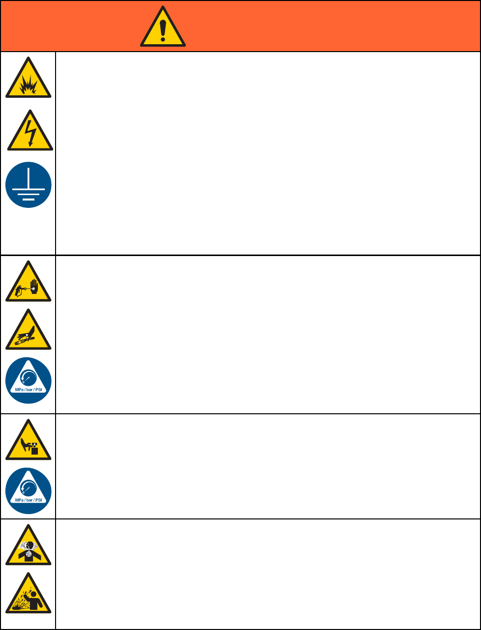
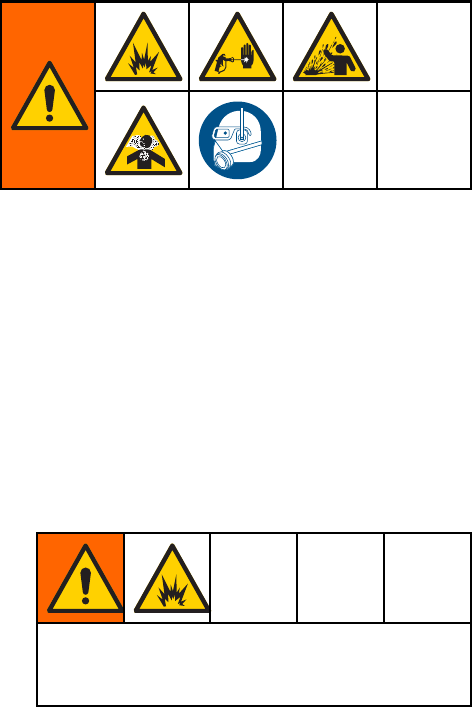
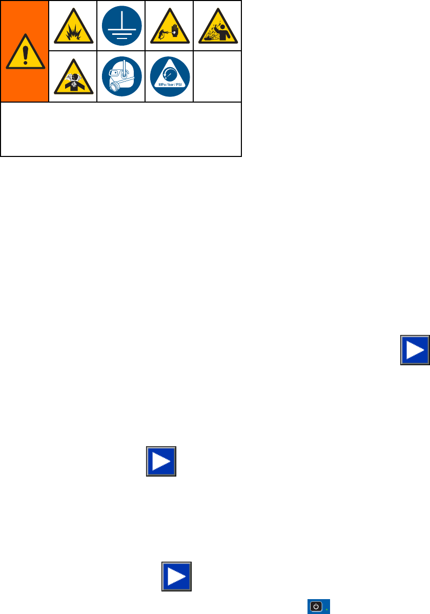
Warnings
The following warnings are for the setup, use, grounding, maintenance and repair of this equipment. The
exclamation point symbol alerts you to a general warning and the hazard symbol refers to procedure-specific
risks. When these symbols appear in the body of this manual or on warning labels, refer backtothese
Warnings. Product-specific hazard symbols and warnings not covered in this section may appear throughout
the body of this manual where applicable.
WARNING
FIRE AND EXPLOSION HAZARD
Flammable fumes, such as solvent and paint fumes, in work area can ignite or explode. To help
prevent fire and explosion:
• Use equipment only in well ventilated area.
• Eliminate all ignition sources; such as pilot lights, cigarettes, portable electric lamps, and
plastic drop cloths (potential static arc).
• Keep work area free of debris, including solvent, rags and gasoline.
• Do not plug or unplug power cords, or turn power or light switches on or off when flammable
fumes are present.
• Ground all equipment in the work area. See Grounding instructions.
•Useonly
grounded hoses.
• Hold gun firmly to side of grounded pail when triggering into pail. Do not use pail liners unless
they are antistatic or conductive.
•Stop operation immediately if static sparking occurs or you feel a shock, Do not use
equipment until you identify and correct the problem.
• Keepaw
orking fire extinguisher in the work area.
ELECTRIC SHOCK HAZARD
This equipment must be grounded. Improper grounding, setup, or usage of the system can
cause electric shock.
•Turn
off and disconnect power at main switch before disconnecting any cables and before
servicing or installing equipment.
• Connect only to grounded power source.
• All electrical wiring must be done by a qualified electrician and comply with all local codes
and regulations.
6332564B
Warnings
WARNING
INTRINSIC SAFETY
Intrinsically safe equipment that is installed improperly or connected to non-intrinsically safe
equipment will create a hazardous condition and can cause fire, explosion, or electric shock.
Follow local regulations and the following safety requirements.
• Be sure your installation complies with national, state, and local codes for the installation of
electrical apparatus in a Class I, Group D, Division 1 (North America) or Class I, Zones 1
and 2 (Europe) Hazardous Location, including all of the local safety fire codes (for example,
NFPA 33, NEC 500 and 516, OSHA 1910.107, etc.).
• To help prevent fire and explosion:
• Do not install equipment approved only for a non-hazardous location in a hazardous
location. See model ID label for the intrinsic safety rating of your model.
• Do not substitute system components as this may impair intrinsic safety.
•Equipment
that comes in contact with the intrinsically safe terminals must be rated for Intrinsic
Safety. This includes DC voltage meters, ohmmeters, cables, and connections. Remove the
unit from the hazardous area when troubleshooting.
SKIN INJECTION HAZARD
High-pressure fluid from dispensing device, hose leaks, or ruptured components will pierce
skin. This may look like just a cut, but it is a serious injury that can result in amputation. Get
immediate surgical treatment.
• Do not point dispensing device at anyone or at any part of the body.
•Donotp
ut your hand over the fluid outlet.
• Do not stop or deflect leaks with your hand, body, glove, or rag.
• Follow the Pressure Relief Procedure when you stop dispensing and before cleaning,
checking, or servicing equipment.
•Tight
en all fluid connections before operating the equipment.
• Check hoses and couplings daily. Replace worn or damaged parts immediately.
MOVING PARTS HAZARD
Moving parts can pinch, cut or amputate fingers and other body parts.
• Keep clear of moving parts.
• Do not operate equipment with protective guards or covers removed.
•Pres
surized equipment can start without warning. Before checking, moving, or servicing
equipment, follow the Pressure Relief Procedure and disconnect all power sources.
TOXIC FLUID OR FUMES
Toxic fluids or fumes can cause serious injury or death if splashed in the eyes or on skin,
inhaled, or swallowed.
• Read MSDSs to know the specific hazards of the fluids you are using.
•St
ore hazardous fluid in approved containers, and dispose of it according to applicable
guidelines.
• Always wear chemically impermeable gloves when spraying, dispensing, or cleaning
equipment.
332564B 7
Warnings
WARNING
PERSONAL PROTECTIVE EQUIPMENT
Wear appropriate protective equipment when in the work area to help prevent serious injury,
including eye injury, hearing loss, inhalation of toxic fumes, and burns. This protective
equipment includes but is not limited to:
•Protectivee
yewear, and hearing protection.
• Respirators, protective clothing, and gloves as recommended by the fluid and solvent
manufacturer.
EQUIPMENT MISUSE HAZARD
Misuse can cause death or serious injury.
• Do not operate the unit when fatigued or under the influence of drugs or alcohol.
• Do not exceed the maximum working pressure or temperature rating of the lowest rated
system component. See Technical Data in all equipment manuals.
•Usefluids
and solvents that are compatible with equipment wetted parts. See Technical Data
in all equipment manuals. Read fluid and solvent manufacturer’s warnings. For complete
information about your material, request MSDS from distributor or retailer.
• Do not leave the work area while equipment is energized or under pressure.
• Turn off all equipment and follow the Pressure Relief Procedure when equipment is not in use.
•Checkeq
uipment daily. Repair or replace worn or damaged parts immediately with genuine
manufacturer’s replacement parts only.
• Do not alter or modify equipment. Alterations or modifications may void agency approvals
and create safety hazards.
• Make sure all equipment is rated and approved for the environment in which youareusingit.
•Useequ
ipment only for its intended purpose. Call your distributor for information.
• Route hoses and cables away from traffic areas, sharp edges, moving parts, and hot surfaces.
• Do not kink or over bend hoses or use hoses to pull equipment.
•Keepc
hildren and animals away from work area.
• Comply with all applicable safety regulations.
8332564B
Important Isocyanate (ISO) Information
Important Isocyanate (ISO) Information
Isocyanates (ISO) are catalysts used in two
component materials.
Isocyanate Conditions
Spraying or dispensing materials containing
isocyanates creates potentially harmful mists,
vapors, and atomized particulates.
Read and understand material manufacturer’s
warnings and material MSDS to know specific
hazards and precautions related to isocyanates.
Prevent inhalation of isocyanate mists, vapors,
and atomized particulates by providing sufficient
ventilation in the work area. If sufficient ventilation
is not available, a supplied-air respirator is required
for everyone in the work area.
To prevent contact with isocyanates, appropriate
personal protective equipment, including
chemically impermeable gloves, boots, aprons,
and goggles, is also required for everyone in the
work area.
Keep Components A and B Separate
Cross-contamination can result in cured
material in fluid lines which could cause serious
injury or damage equipment. To prevent
cross-contamination:
•Never interchange component A and component
B wetted parts.
• Never use solvent on one side if it has been
contaminated from the other side.
Moisture Sensitivity of Isocyanates
Exposure to moisture (such as humidity) will cause
ISO to partially cure; forming small, hard, abrasive
crystals, which become suspended in the fluid.
Eventually a film will form on the surface and the ISO
will begin to gel, increasing in viscosity.
NOTICE
Partially cured ISO will reduce performance and
the life of all wetted parts.
• Always use a sealed container with a desiccant
dryer in the vent, or a nitrogen atmosphere.
Never store ISO in an open container.
• Keep the ISO pump wet cup or reservoir (if
installed) filled with appropriate lubricant. The
lubricant creates a barrier between the ISO and
the atmosphere.
• Use only moisture-proof hoses compatible with
ISO.
• Never use reclaimed solvents, which may
contain moisture. Always keep solvent
containers closed when not in use.
• Always lubricate threaded parts with an
appropriate lubricant when reassembling.
NOTE: The amount of film formation and rate of
crystallization varies depending on the blend of ISO,
the humidity, and the temperature.
Changing Materials
NOTICE
Changing the material types used in your
equipment requires special attention to avoid
equipment damage and downtime.
•When
changing materials, flush the equipment
multiple times to ensure it is thoroughly clean.
•Alw
ays clean the fluid inlet strainers after
flushing.
•Che
ck with your material manufacturer for
chemical compatibility.
•Wh
en changing between epoxies and urethanes
or polyureas, disassemble and clean all fluid
components and change hoses. Epoxies often
have amines on the B (hardener) side. Polyureas
oftenhaveaminesontheA(resin)side.
332564B 9
General Information
General Information
• Reference numbers and letters in parentheses
in the text refer to numbers and letters in the
illustrations.
• Be sure all accessories are adequately sized and
pressure-rated to meet system requirements.
• To protect the screens from paints and solvents,
clear-plastic protective shields (10 per pack) are
available. Order Part No. 197902 for the Advanced
Display Module. Clean the screens with a dry cloth
if necessary.
10 332564B
Advanced DisplayModule(ADM)
Advanced Display Module (ADM)
ADM Display
The ADM display shows graphical and text
information related to setup and spray operations.
For detail on the display and individual
screens, see Run Mode Screens, page 58,or
Setup Mode Screens, page 66.
Keys are used to input numerical data, enter setup
screens, navigate within a screen, scroll through
screens, and select setup values.
NOTICE
To prevent damage to the softkey buttons, do not
press the buttons with sharp objects such as pens,
plastic cards, or fingernails.
1 2 3
4 5 6
7 8 9
0 .
Figure 7 Advanced Display Module
USB Download Procedure
Use the USB port on the ADM to download or upload
data.
1. Enable USB downloads. See
Advanced Screen 3, page 83.
2. Remove the cover from the USB port on the
bottom of the ADM. Insert the USB drive.
3. During the download, USB BUSY appears on the
screen.
4. When the download is complete, USB IDLE
appears on the screen. The USB drive may then
be removed.
NOTE: If the download operation takes longer
than 60 seconds, the message disappears. To
determine if the USB is busy or idle, check the
Error Status bar on the screen. If idle, remove
the USB.
5. Insert the USB flash drive into the USB port of
the computer.
6. The USB flash drive window automatically opens.
If it does not, open the USB flash drive from
within Windows® Explorer.
7. Open Graco folder.
8. Open system folder. If downloading data from
more than one system, there will be more than
one folder. Each folder is labeled with the
corresponding serial number of the ADM. (The
serial number is on the back of the ADM.)
9. Open DOWNLOAD folder.
10. Open LOG FILES folder labeled with the highest
number. The highest number indicates the most
recent data download.
11. Open logfile. LogfilesopeninMicrosoft®
Excel® by default if the program is installed.
They also can be opened in any text editor of
Microsoft® Word.
NOTE: All USB logs are saved in Unicode
(UTF-16) format. If opening the log file in
Microsoft Word, select Unicode encoding.
12. Always reinstall the USB cover after removing
the USB, to keep the drive free of dirt and dust.
332564B 11
Advanced DisplayModule(ADM)
USB Upload Procedure
Use this procedure to install a system configuration
file and/or a custom language file.
1. If necessary, follow the USB Download
Procedure, to automatically generate the proper
folder structure on the USB flash drive.
2. Insert the USB flash drive into the USB port of
the computer.
3. The USB flash drive window automatically opens.
If it does not, open the USB flash drive from
within Windows Explorer.
4. Open the Graco folder.
5. Open the system folder. If working with more
than one system, there will be more than one
folder within the Graco folder. Each folder is
labeled with the corresponding serial number of
the ADM. (The serial number is on the back of
the module.)
6. If installing the system configuration settings file,
place SETTINGS.TXT file into UPLOAD folder.
7. If installing the custom language file, place
DISPTEXT.TXT file into UPLOAD folder.
8. Remove the USB flash drive from the computer.
9. Install the USB flash drive into the USB port of
the ProMix PD2K system USB port.
10. During the upload, USB BUSY displays on the
screen.
11. Remove the USB flash drive from the USB port.
NOTE: If the custom language file was installed,
users can now select the new language from the
Language drop-down menu in the Advanced Setup
Screen 1.
12332564B
Advanced DisplayModule(ADM)
ADM Keys and Indicators
NOTICE
To prevent damage to the softkey buttons, do not
press the buttons with sharp objects such as pens,
plastic cards, or fingernails.
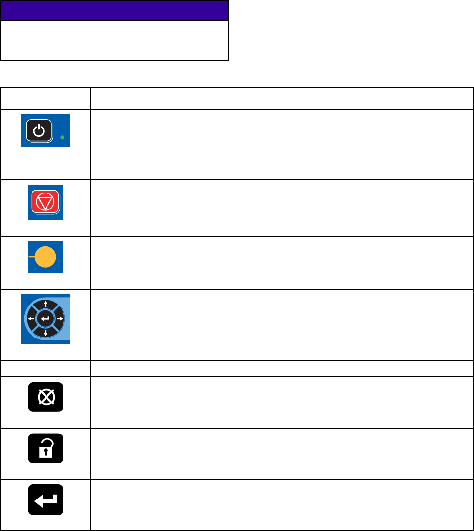
Table 1 : ADM Keys and Indicators
Key Function
Startup/Shutdown
Key and Indicator
Press to startup or shutdown the pump/motor.
• Solid green indicates that power is applied to the motor.
• Solid yellow indicates that power to the motor is off.
• Blinking green or yellow indicates that the system is in Setup mode.
Stop
Press to immediately stop the system and remove motor power.
Soft Keys
Press to select the specific screen or operation shown on the display directly next to
each key. The top left soft key is the Edit key, which allows access to any settable
fields on a screen.
Navigation Keys
•
Left/Right Arrows:
Use to move from screen to screen.
•
Up/Down Arrows:
Use to move among fields on a screen, items on a dropdown
menu, or multiple screens within a function.
Numeric Keypad Use to input values. See ADM Display, page 11.
Cancel
Use to cancel a data entry field.
Setup
Press to enter or exit Setup mode.
Enter
Press to choose a field to update, to make a selection, to save a selection or value, to
enter a screen, or to acknowledge an event.
332564B 13
Advanced DisplayModule(ADM)
Soft Key Icons
The following icons appear in the ADM display,
directly to the left or right of the soft key which
activates that operation.
NOTICE
To prevent damage to the softkey buttons, do not
press the buttons with sharp objects such as pens,
plastic cards, or fingernails.
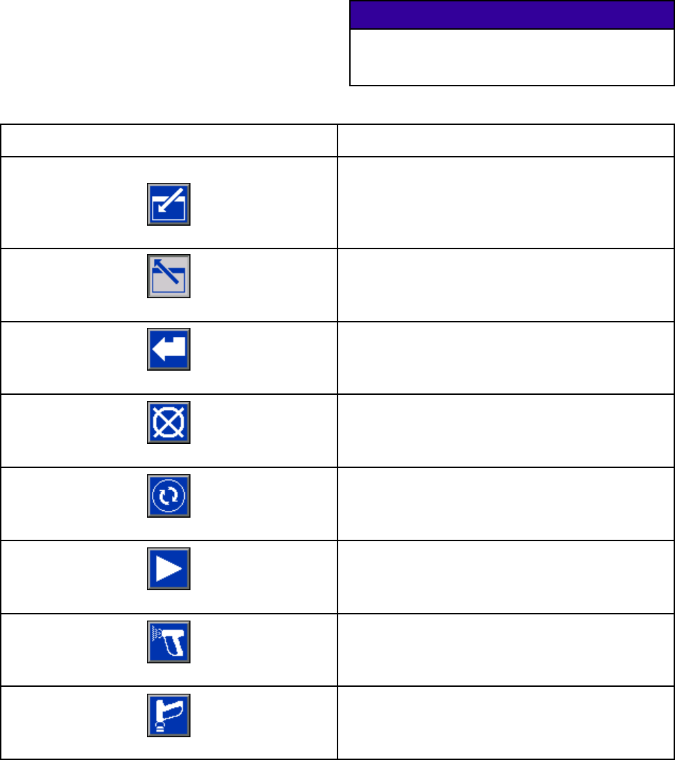
Table 2 : Soft Key Functions
Key Function
Enter Screen
Press to enter screen for editing. Highlights editable
data on a screen. Use Up/Down arrows to move
between data fields on the screen.
Exit Screen
Press to exit screen after editing.
Accept
Press to accept calibration value.
Cancel
Press to cancel or reject calibration value.
Prime Pump
Press to start a pump priming procedure.
Line/Fill/Run
Press to start a line fill procedure.
Mix
Press to start a spray procedure.
Purge
Press to start a purge procedure.
14332564B
Advanced DisplayModule(ADM)
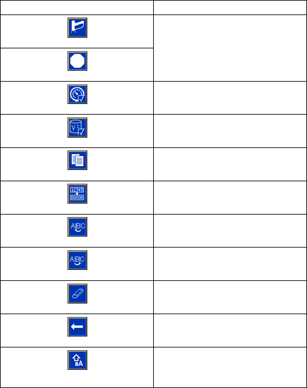
Key Function
Standby
Stop
Press to stop all pumps and put system in Standby.
Pressure Check
Presstostartapumppressurecheck.
Volume Check
Press to start a pump volume check.
Job Complete
Press to log the material usage and increment the
job number.
Counter Reset
Press to reset the current usage counter.
Move Cursor to Left
Appears on the User ID Keyboard screen. Use to
move cursor to the left.
Move Cursor to Right
Appears on the User ID Keyboard screen. Use to
move cursor to the right.
Erase All
Appears on the User ID Keyboard screen. Use to
erase all characters.
Backspace
Appears on the User ID Keyboard screen. Use to
erase one character at a time.
Upper Case/Lower Case
Appears on the User ID Keyboard screen. Use to
change case (upper/lower).
332564B 15
Advanced DisplayModule(ADM)
Navigating the Screens
There are two sets of screens:
• The Run screens control mixing operations and
display system status and data.
•TheSetupscr
eens control system parameters and
advanced features.
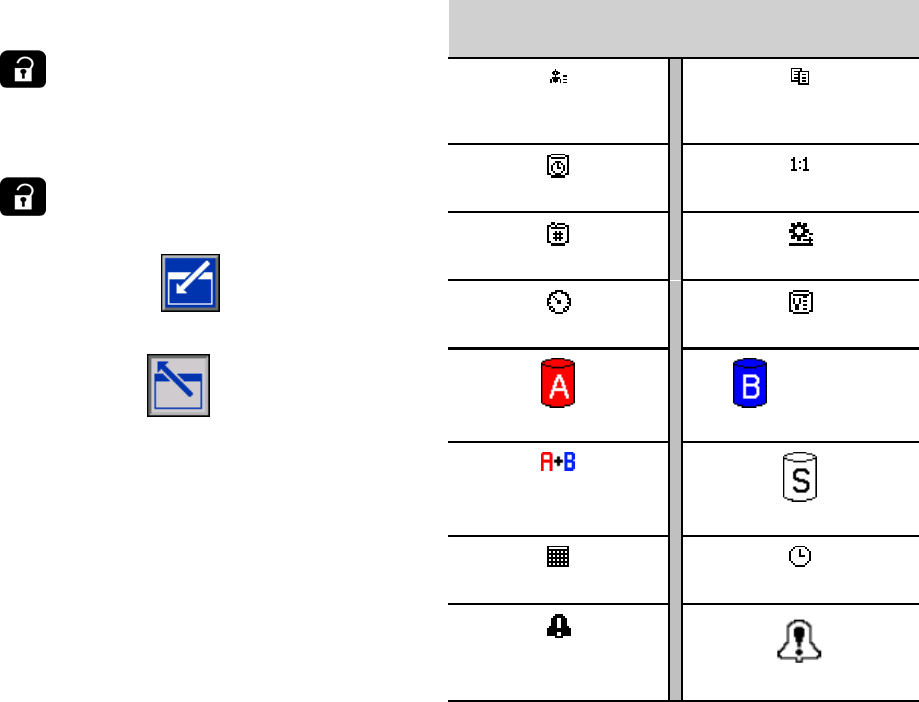
Press on any Run screen to enter the Setup
screens. If the system has a password lock, the
Password screen displays. If the system is not locked
(password is set to 0000), System Screen 1 displays.
Press on any Setup screen to return to the
Home screen.
Press the Enter soft key to activate the editing
function on any screen.
Press the Exit soft key to exit any screen.
Use the other softkeys to select the function adjacent
to them.
Screen Icons
As you move through the screens, you will notice
that icons are used frequently to simplify global
communication. The following descriptions explain
what each icon represents.
Screen Icons
User ID
Job Number
Potlife Target Ratio
Recipe Number Flow Rate
Pressure Volume
Material A
Material B
Material A+B
Solvent
Calendar Time
Alarm/Advisory
Deviation
16 332564B
Pre-Operation Tasks
Pre-OperationTasks
Pre-operation Checklist
Go through the Pre-Operation Checklist daily, before
each use.
✔Checklist
System grounded
Verify all grounding connections
were made. See Grounding in the
Installation manual.
All connections tight and correct
Verify all electrical, fluid, air, and
system connections are tight and
installedaccordingtotheInstallation
manual.
Fluid supply containers filled
Check component A and B and
solvent supply containers.
Dose valves set
Check that dose valves are set
1–1/4 turns open. Start with
the settings recommended in
Valve Settings, page 18, then adjust
as needed.
Fluid supply valves open and
pressure set
The recommended component A and
B fluid supply pressures are 1/2 to 2/3
of the target spray pressure.
NOTE: Low pressure systems may
be set within a range of ± 100 psi (0.7
MPa, 7 bar); high pressure systems
may be set within a range of ± 300 psi
(2.1 MPa, 21 bar). If the inlet pressure
is higher than the outlet pressure,
ratio accuracy may be affected.
Solenoid pressure set
85-100 psi inlet air supply (0.6-0.7
MPa, 6-7 bar).
Power On
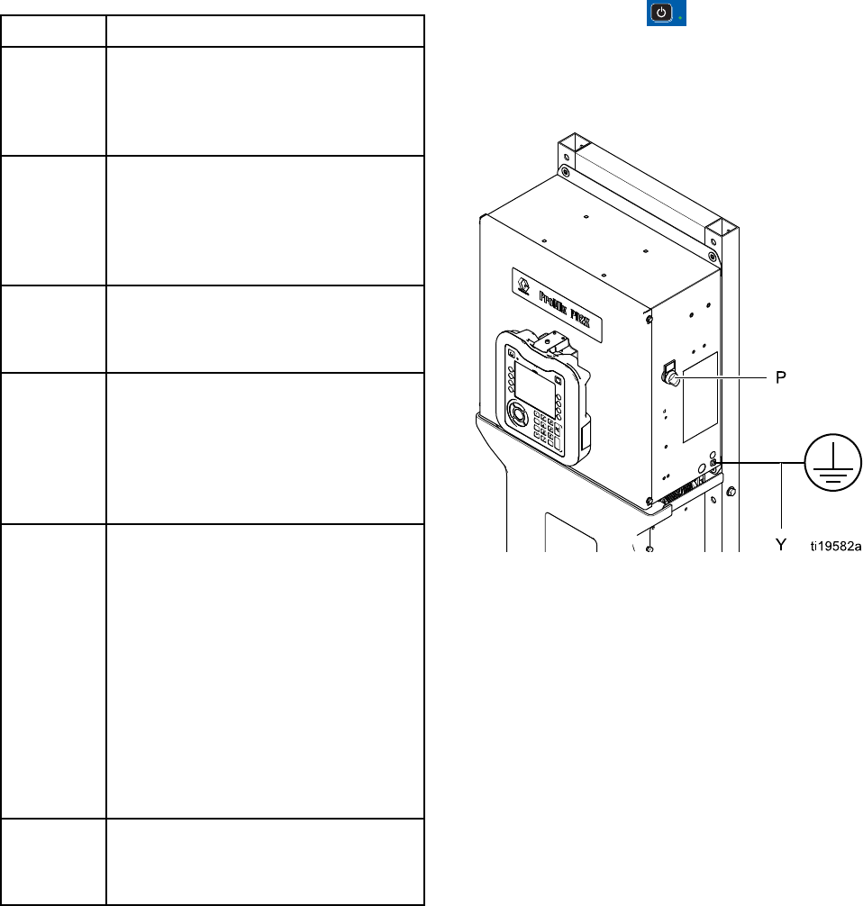
1. Turn the AC Power Switch (P) ON (I = ON,
0=OFF).
2. The Graco logo will display while the system
initializes, followed by the Home screen.
3. Press the Start key . The system status will
change from “System Off” to “Startup.” Once
the pumps are powered and are in the Home
position, the system status will change from
“Startup” to “Standby.”
Figure 8 Power Switch
332564B 17
Pre-Operation Tasks
Initial System Setup
1. Change optional setup selections to
desired parameters, as described in
Setup Mode Screens, page 66.
2. Set recipe and flush information as
described in Recipe Screen, page 72 and
Flush Screen, page 73.
Flush Before Using Equipment
The pump fluid section was tested with lightweight
oil, which is left in the fluid passages to protect parts.
To avoid contaminating your fluid with oil, flush the
equipment with a compatible solvent before using
the equipment.
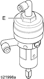
Valve Settings
Dose valves and purge valves are factory set with the
hex nut (E) 1-1/4 turns out from fully closed.
Figure 9 Valve Adjustment
18 332564B
Pressure Relief Procedure
Pressure Relief Procedure
Follow the Pressure Relief Procedure
whenever you see this symbol.
This equipment stays pressurized until pressure
is manually relieved. To help prevent serious
injury from pressurized fluid, such as skin injection,
splashing fluid and moving parts, follow the
Pressure Relief Procedure whenyoustopspraying
and before cleaning, checking, or servicing the
equipment.
Without Color Change
NOTE: The following procedure relieves all fluid and
air pressure in the system. Use your control interface
to issue the necessary commands to your system.
1. Turn off the supply pumps. Open the drain valve
on the supply line fluid filter to relieve pressure
in the supply line.
2. Command the system to Standby. Trigger the
spray device to relieve pressure.
3. Flush the remote mix manifold and spray device.
See Flush Mixed Material, page 22.
4. Shut off the solvent supply pump. To relieve
pressure, command the system to Purge and
trigger the spray device. When the pressure is
relieved, command the system to Standby to
avoid getting a Purge Incomplete alarm.
5. If pressure remains in the solvent line between
the solvent supply pump and the solvent valve:
• VERY SLOWLY loosen a fitting to relieve
pressure gradually.
• Loosen the fitting completely.
With Color Change
NOTE: The following procedure relieves all fluid and
air pressure in the system.
1. Turn off the supply pumps. Open the drain valve
on the supply line fluid filter to relieve pressure in
the supply lines. Do this for each color.
If using an electrostatic gun, shut off the
electrostatics before flushing the gun.
2. Trigger the gun to relieve pressure. From
Maintenance Screen 4 on the ADM, check the
box in the field labeled Gun for each color in the
system.
3. Command the system to Purge. Hold the gun
trigger open after the solvent valve shuts off to
relieve all pressure.
4. Set the system to Recipe 0 to flush the pumps
and to purge to the spray device. When flushing
is complete the system will go to Standby.
5. Shut off the solvent supply pump. Set the system
to Recipe 0 to flush solvent from the pumps and
to purge to the spray device. Command the
system to Standby after just a couple of seconds,
to avoid getting a Purge Incomplete alarm.
6. If pressure remains in the solvent line between
the solvent supply pump and the solvent valve:
•VERY
SLOWLY loosen a fitting to relieve
pressure gradually.
• Loosen the fitting completely.
7. Verify on the ADM Home Screen that neither
pump is showing any pressure.
NOTE: If pressure remains in the solvent line
between the solvent supply pump and the solvent
valve,VERYSLOWLYloosenafittingtorelieve
pressure gradually.
332564B 19
Operation Using Automatic Display Module (ADM)
Operation Using Automatic Display Module (ADM)
Prime and Fill the System
NOTE: See Run Mode Screens, page 58, for further
screen information, if needed.
NOTE: You must prime the input lines to the pumps
or the inputs to the color change valves before
priming the pump and filling the entire system.
1. If using an electrostatic gun, shut off the
electrostatics before filling the lines.
2. Adjust the main air pressure. To ensure proper
operation, set the main air pressure as close to
100 psi (0.7 MPa, 7.0 bar) as possible. Do not
uselessthan85psi(0.6MPa,6.0bar).
3. If this is the first time starting up the system, or if
lines may contain air, purge as instructed under
.Flush the System, page 23 The equipment
was tested with lightweight oil, which should be
flushed out to avoid contaminating your material.
4. If the system is powered down, press on the
ADM. Make sure that the system is in Standby
mode.
5. Verify that the recipes and the flush sequences
are programmed correctly by checking
the Recipe Screen, page 72 and the
Flush Screen, page 73.
6. Enable the manual override on System Screen 5.
7. Go to the Fill Screen, page 63.
8. Select the desired color to load. Press the Prime
Pump key . The color will load the pump
through the color stack and out the outlet stack
dump valve.
NOTE: In a single color system, skip step 7 and
prime the pump out to the gun.
9. Press the Fill Line key to run color out to
the remote mix manifold. The pump will run until
you press the Stop key to stop the pump.
10. Trigger the gun into a grounded reservoir or
purge receptacle until the line is full, then press
the Stop key .
11. Repeat for all material lines.
20 332564B

Operation Using Automatic Display Module (ADM)
Spraying
To spray in a multiple color system, also see
Multiple Color Systems, page 87.
NOTE: See Run Mode Screens, page 58,forfurther
screen information, if needed.
1. Command the system to Mix. The system will
load the correct mixed material volume.
NOTE: The system will automatically run a Mix
Fill if the recipe is not currently loaded into the
system. The Mix Fill volume calculation includes
the remote mix manifold volume and the mixed
material hose volume. The mixed material hose
volume is determined by the gun hose length and
diameter entered in System Screen 3, page 69,
and the remote to mix hose length and diameter
also entered in System Screen 3, page 69.
2. Adjust the flow rate by changing the target
pressure (in Pressure Mode)orthetargetflow
rate (in Flow Mode) on the Spray Screen or
through the PLC. The fluid flow rate shown on the
Spray screen is the combined total of component
A and B out of the spray device.
NOTE: If spray pressure is adjusted at the ADM
while spraying, it is not saved in the recipe until
the system is put in Standby. This changes the
pressure in the desired recipe.
3. Turn on atomizing air to the gun. Check the spray
pattern as instructed in your spray gun manual.
NOTICE
Do not allow a fluid supply tank to run empty.
This can damage the pumps and lead to the
proportioning of fluid and air that meets the ratio
and tolerance settings of the equipment. This can
further result in spraying uncatalyzed or poorly
catalyzed material.
332564B 21
Operation Using Automatic Display Module (ADM)
Purging
To purge one color and fill with a new color, see
Color Change, page 87.
Flush Mixed Material
There are times when you only want to purge the
remote mix manifold and the spray device, such as:
• end of potlife
• breaks in spraying that exceed the potlife
• overnight shutdown or end of shift
• before servicing the remote mix manifold, hose or
gun.
1. Command the system to Standby.
2. Ifyouareusingahighpressurespraydeviceor
an electrostatic gun, shut off the atomizing air.
To reduce risk of fire and explosion, if using
an electrostatic gun, shut off the electrostatics
before flushing the gun.
3. Trigger the spray device to relieve pressure.
4. Set the solvent supply pressure regulator at the
lowest pressure possible. Generally a setting
of 25–50 psi (0.18–0.35 MPa, 1.8–3.5 bar) is
sufficient.
5. CommandthesystemtoPurgeAorPurgeB.
Trigger the spray device into a grounded metal
pail until the purge sequence is complete. When
done purging, the system automatically switches
to Standby mode, signalling the spray device to
stop spraying.
6. If the system is not completely clean, repeat Step
5.
NOTE: For optimal efficiency, adjust purge
sequence times so only one cycle is required.
7. Trigger spray device to relieve pressure.
8. Adjust the solvent supply regulator back to its
normal operating pressure.
NOTE: The remote mix manifold and gun remain full
of solvent after purging.
22332564B
Operation Using Automatic Display Module (ADM)
Flush the System
To avoid fire and explosion, always ground
equipment and waste container. To avoid injury
from splashing, always flush at lowest possible
pressure.
Follow this procedure before:
• the first time material is loaded into the equipment
•servicing
• shutting down equipment for an extended period
of time
• putting equipment into storage
Single Color System
1. Relieve the pressure. See
Pressure Relief Procedure, page 19.
2. Disconnect the color and catalyst supply lines
from the pump inlet manifolds, and connect
regulated solvent supply lines.
3. Set the solvent supply pressure regulator at the
lowest pressure possible. Generally a setting
of 25–50 psi (0.18–0.35 MPa, 1.8–3.5 bar) is
sufficient.
4. Enable manual override on
System Screen 5, page 71.
5. On the ADM, go to the Fill screen. Set the
Material to Color (A). Press . The system
will pump solvent through pump A all the way to
the gun.
6. Hold a metal part of the spray device firmly to a
grounded metal pail. Trigger the spray device
until clean solvent dispenses.
7. On the ADM, go to the Fill screen. Set the
Material to Catalyst (B). Press .The
system will pump solvent through pump B all the
way to the gun.
8. Relieve the pressure. See
Pressure Relief Procedure, page 19
Color Change System
1. Relieve the pressure. See
Pressure Relief Procedure, page 19.
2. Attach regulated solvent supply lines as follows:
•Multiple color/single catalyst system: On the
color side, do not disconnect the color supply
line from the inlet manifold of Pump A. Instead,
connect a regulated solvent supply line to the
designated solvent valve on the color valve
manifold. On the catalyst side, disconnect
the catalyst supply line from the inlet manifold
of Pump B, and connect a regulated solvent
supply line.
•Multiple color/multiple catalyst system:
Connect regulated solvent supply lines to
the designated solvent valves on the color
and catalyst valve manifolds. Do not connect
solvent supply lines directly to the inlet
manifolds of the pumps.
3. Set the solvent supply pressure regulator at the
lowest pressure possible. Generally a setting
of 25–50 psi (0.18–0.35 MPa, 1.8–3.5 bar) is
sufficient.
4. On the ADM, go to the Fill screen. Set the
Material to Solvent. Press . The system
will pump solvent from the color valve inlet all the
way to the gun.
5. Hold a metal part of the gun firmly to a grounded
metal pail. Trigger the gun until clean solvent
dispenses.
6. Repeat for each color line.
7. Relieve the pressure. See
Pressure Relief Procedure, page 19
Shutdown
1. Flush out the mixed material to avoid potlife errors
and fluid setup in the lines. See Purging, page 22.
2. Follow the Pressure Relief Procedure, page 19.
3. Close the main air shutoff valve on the air supply
line and on the control box.
4. Press on the Display Module to turn off
power to the pumps.
5. Shut off system power (0 position).
332564B 23

Operation Using a Programmable Logic Controller (PLC)
Operation Using a Programmable Logic Controller
(PLC)
Network Communications and
Discrete I/O
The ProMix PD2K Automatic system does not use
a Booth Control module. Instead, it uses Network
Communications and has optional Discrete I/O
features to drive the system remotely.
Some automation control elements of the
ProMix PD2K can be driven by a discrete
input
or
network communications. These
options need to be configured at the ADM (see
System Screen 5, page 71). The following features
can be set to ‘Discrete’ or ‘Network’:
•Flow Control – Means of adjusting the control set
point (see Flow Control Set Point below).
•Gun Trigger – Means of signaling the ProMix PD2K
when the spray device is triggered.
NOTE: The Manual Override check box enables a
user to operate the system before the automation
(PLC) is available. Manual Override can be used to
run all functions of the system if a proper gun trigger
signal is provided. It is not intended to be the main
mode of control. Graco recommends that Manual
Override be disabled during normal operation to
avoid driving the system in a way that conflicts with
the automation sequence.
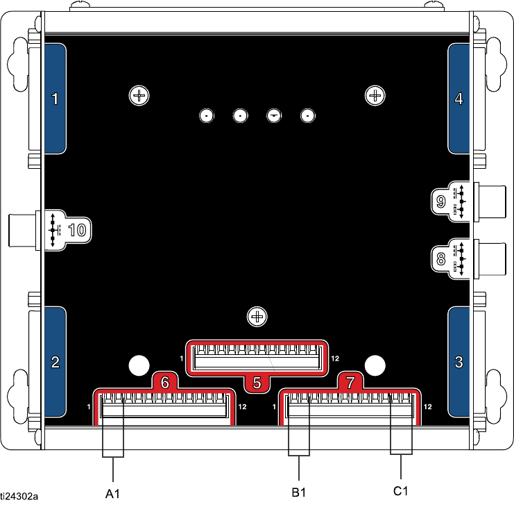
Discrete I/O
The ProMix PD2K does not supply power for
Discrete I/O. A clear understanding of these inputs
is necessary to properly integrate the ProMix PD2K
with the PLC or networking device. Input and output
connections are made at the Discrete I/O terminal
strips on the Enhanced Fluid Control Module (EFCM)
inside the control box.
Table 3 and Figure 2 show where discrete I/O
connections are made on the ProMix PD2K.
Table 3 PD2K Discrete I/O Connections
I/O
Description
EFCM
Connector
Pins Type
Gun Trigger
Input
61,2
Normally Open
Contact
ControlSet
Point
71,2 4-20 mA Input
Safety
Interlock
Input
711,12 Normally Open
Contact
24332564B
Operation Using a Programmable Logic Controller (PLC)
Digital Inputs
•Safety Interlock: This normally open contact works
like a soft emergency stop button. If the ProMix
PD2K reads the input as CLOSED it interrupts
system operation and removes power from the
pumps regardless of the current operating mode.
If the input is read as OPEN, the system operates
normally
NOTE: This digital input is always enabled.
Do not toggle this input to put the system into
Standby mode.
•Gun Trigger: This normally open (maintained)
contact provides a signal to the system to indicate
whether or not a spray device is triggered. This
input provides timing for alarm functions and also
drives the flow control algorithm. If the input is
OPEN the system operates as though the spray
device is off. The input must be maintained
CLOSED to signal that the spray device is
triggered.
NOTE: The Gun Trigger discrete input must be
enabled via Configure Screen 5 on the ADM. If it
is set to ‘Network’ the discrete input is ignored and
the spray device trigger signal is handled via the
network communications.
If enabled, it is imperative that this signal be sent
any time the spray device is triggered. Without the
signal, the flow control features will not work.
Analog Inputs
Flow Control Set Point: When enabled, this 4-20mA
signal input is used to set and adjust the operating
flow control set point. The ProMix PD2K scales the
set point linearly from 0 to the Max Set Point setting
(see System Screen 5, page 71).
Examples
,
•In Flow Control Mode: If the Max Set Point is 500
cc/min, a 4mA signal is 0 cc/min and a 20mA signal
is 500 cc/min.
•In Pressure Control Mode: If the Max Set Point is
500 psi, a 4mA signal is 0 psi and a 20mA signal
is 500 psi.
NOTE: The Flow Control discrete input must be
enabled via Configure Screen 5 on the ADM. If
set to ‘Network’ the discrete input is ignored and
set point adjustment is handled via the network
communications.
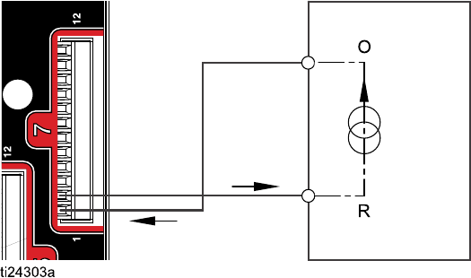
4–20 mA Flow Control Set Point Input
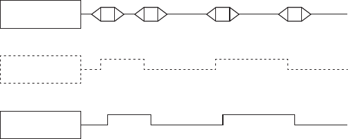
PD2K Discrete Input PLC (4–20 MA Signal)
Figure10
O = Output
R=Return
332564B 25

Operation Using a Programmable Logic Controller (PLC)
Communication Gateway Module (CGM) Details
CGM Overview
The CGM provides a control link between the PD2K
system and a selected fieldbus. This linkage provides
the means for remote monitoring and control by
external automation systems.
NOTE: The following system network configuration
files are available at www.graco.com.
• EDS file: DeviceNet or Ethernet/IP fieldbus
networks
• GSD file: PROFIBUS fieldbus networks
• GSDML file: PROFINET fieldbus networks
CGM Kits
The PD2K system comes with a Modbus TCP CGM.
Kits for other communication protocols are available.
Each kit includes all parts needed to install the
CGM, along with Manual 334494, which contains
installation instructions applicable to any kit. See
Manual 312864 or Manual 334183 for information
specific to each protocol, plus repair parts for each
assembly.
CGM Part No. Fieldbus Manual
CGMDNO DeviceNet 312864
CGMEPO EtherNet/IP 312864
CGMPBO PROFIBUS 312864
CGMPNO PROFINET 312864
24W462 Modbus TCP 334183
332564B 27

Operation Using a Programmable Logic Controller (PLC)
Network Communication I/O Data Map
ProMix PD2K Network Outputs
The ProMix PD2K Network Outputs are Read-Only
and should be treated as inputs to a PLC
or other networking device. These registers
provide various system and component status,
measurement, and set point values. See
Network Output Data Map (Read Only), page 33.
OUTPUT REGISTER 00: Current System Mode
The Current System Mode register contains a number that indicates the current operation mode of the PD2K
system.
Number Operation Mode Description
1Pump Off The pumps are currently powered down and the system is not in
operation.
2Recipe Change The system is in the process of a color change sequence.
3Recipe Change: Purge
A
The system is purging material A as part of a recipe change.
4Recipe Change: Purge
B
The system is purging material B as part of a recipe change.
5Recipe Change: Fill The system is filling the hose from the remote valves to the mix
manifold with material as part of a recipe change.
6MixFil
lThe system is mixing material at ratio through the mix manifold
and out the gun.
7Mix The system is currently mixing/spraying material.
8MixI
dle The system has paused mix operation due to the absence of a gun
trigger signal.
9 Purge A The system is purging material A while in Standby.
10 Purge B The system is purging material B while in Standby.
11 Standby: Mix Ready The system has a valid recipe loaded out to the gun.
12 Standby: Fill Ready The system has a valid recipe loaded in the pumps, but not in the
gun.
13Standby: Mix Not Ready The system requires that a recipe change operation be completed.
14 Standby: Alarm The system has an active alarm.
28 332564B

Operation Using a Programmable Logic Controller (PLC)
OUTPUT REGISTERS 01, 02, 03, and 04: Pump
Status
ThePumpStatu
s registers contain a number that
indicates the state of Pumps 1 — 4. This status can
be used for general monitoring of the pump state,
or as an indicator for driving independent pump
operations. See INPUT REGISTER 02: Flush/Prime
Pump Command, page 36.
Table4PumpS
tates for Output Registers 01–04
Nu-
m-
ber
Pump
State
Description
0Off The pump is powered down or
not enabled.
1Standby The pump is powered but not
currently active.
2 Busy The pump is currently in
arecipec
hange or mixing
operation.
3 Flushing The pump is currently flushing
with solvent
4 Priming The pump is currently priming
with material.
OUTPUT REGISTER 05: Actual Mix Flow
The Actual Mix Flow register reports back the
instantaneous mixing flow rate in cc/min.
NOTE: This register is valid only during a mix
operation.
OUTPUT REGISTER 06: Actual Mix Ratio
The Actual Mix Ratio register contains the
instantaneous calculated mix ratio.
• The value reported is the ratio antecedent
multiplied by 100. The ratio consequent is always
1.
Example
: Value = 250 >> A mix ratio of 2.5:1
(Material A to Material B)
•Ift
he current recipe ratio is 0:1 (1K recipe) this
value will be 0.
This register is valid only during a mix operation.
OUTPUT REGISTER 07: Actual Mix Potlife
Remaining
The Actual Potlife Remaining register contains
the current amount of time remaining in the active
recipe’s potlife in seconds.
NOTE: If potlife is disabled for the active recipe or at
initial startup this value will be 0xFFFFFFFF.
OUTPUT REGISTER 08: Active Recipe Number
TheActiveR
ecipe Number register contains the
number of theactiverecipe(1–60).
• This value is 0 if the system was flushed.
• This value is 61 if the system does not know the
current loaded recipe, if the recipe is invalid, or at
initial startup.
OUTPUT REGISTER 09: Active Recipe Material A
The Active Recipe Material A register contains the
number of the Color (1 – 30) that is associated with
the current recipe.
• This value is 0 if the system was flushed.
• This value is 61 if the current recipe is invalid or at
initial startup.
OUTPUT REGISTER 10: Active Recipe Material B
The Active Recipe Material B data register contains
the number of the Catalyst (31 – 34) that is associated
with the current recipe.
• This value is 0 if the system was flushed.
• This value is 61 if the current recipe is invalid or at
initial startup.
• This value is 0 if the current recipe ratio is 0:1 (1K
recipe).
OUTPUT REGISTER 11: Active Recipe Material A
Flush Sequence
The Active Recipe Material A Flush Sequence
register contains the number of the Flush Sequence
(1 – 5) that is associated with the Color pump of the
current recipe.
If the current recipe is invalid this value reflects the
Flush Sequence associated with Material A pump
of recipe 0.
332564B 29
Operation Using a Programmable Logic Controller (PLC)
OUTPUT REGISTER 12: Active Recipe Material B
Flush Sequence
The Active Recipe Material B Flush Sequence
register contains the number of the Flush Sequence
(1 – 5) that is associated with the Catalyst pump of
the current recipe.
• If the current recipe is invalid this value reflects the
Flush Sequence associated with Material B pump
of recipe 0.
• This value is 0 if the current recipe ratio is 0:1 (1K
recipe)
OUTPUT REGISTER 13: Active Recipe Ratio Set
Point
The Active Recipe Ratio Set Point data register
contains the ratio set point associated with the
current recipe.
• The value reported is the ratio antecedent
multiplied by 100. The ratio consequent is always
1.
Example
: Value = 250 >> A mix ratio of 2.5:1
(Material A to Material B)
• This value is 0 if the current recipe ratio is 0:1 (1K
recipe)
OUTPUT REGISTER 14: Active Recipe Potlife
Timeout Set Point
The Active Recipe Potlife Timeout Set Point register
contains the set point for the potlife time associated
with the current recipe in minutes.
• This value is 0 if the potlife time is disabled for the
current recipe.
OUTPUT REGISTER 15: Actual Pump 1 Flow Rate
OUTPUT REGISTER 16: Actual Pump 2 Flow Rate
OUTPUT REGISTER 17: Actual Pump 3 Flow Rate
OUTPUT REGISTER 18: Actual Pump 4 Flow Rate
These registers contain the instantaneous flow rate
of Pumps 1–4 in cc/min.
This is NOT the mix flow rate. For mix flow rate see
Actual Mix Flow
.
OUTPUT REGISTER 19: Actual Pump 1 Fluid
Pressure
OUTPUT REGISTER 20: Actual Pump 2 Fluid
Pressure
OUTPUT REGISTER 21: Actual Pump 3 Fluid
Pressure
OUTPUT REGISTER 22: Actual Pump 4 Fluid
Pressure
These registers contain the instantaneous fluid
pressure on the outlet of pumps 1–4 in PSI.
OUTPUT REGISTER 23: Gun 1 Trigger Input Status
The Gun 1 Trigger Input Status register contains the
status of the Gun Trigger Discrete Input.
•Thevaluei
s0iftheinputisOPEN(gunnot
triggered).
•Thevalue
is 1 if the input is CLOSED (gun
triggered).
This data register is valid only for systems configured
to use the discrete input for the Gun Trigger.
See
Gun Trigger Signal, page 71
.
OUTPUT REGISTER 24: Gun 2 Trigger Input Status
OUTPUT REGISTER 25: Gun 3 Trigger Input Status
OUTPUT REGISTER 26: Gun 4 Trigger Input Status
These registers are not used.
OUTPUT REGISTER 27: Safety Interlock Input
Status
The Safety Interlock Input Status register contains
the status of the Safety Interlock Discrete Input.
• The value will be 0 if the input is OPEN (Normal).
• The value will be 1 if the input is CLOSED (Safety
Stop).
See Safety Interlock in Digital Inputs, page 25
.
OUTPUT REGISTERS 28 – 36: DCS Command
Structure
See Dynamic Command Description, page 47.
30 332564B
Operation Using a Programmable Logic Controller (PLC)
OUTPUT REGISTER 37: Time
TheTimeregis
ter contains a count of total seconds
since the Unix Epoch (January 1, 1970).
• The actual value reported is not important. This
register should be used for diagnosing status of
communication between the ProMix PD2K and the
networking device.
This register is NOT currently available with the
Modbus Communications Gateway Module.
OUTPUT REGISTER 38 – 40: Software Version
The Software Version registers contain the “major,”
“minor,” and “build” revisions of the ADM software.
These registers are NOT currently available with the
Modbus Communications Gateway Module.
332564B 31


Operation Using a Programmable Logic Controller (PLC)
Network Output Data Map (Read Only)
Network
Output ID
Modbus
Register
Parameter Name Data Type Units Range
1=PumpOff
2 = Recipe Change
3 = Recipe Change:
Purge A
4=RecipeCh
ange:
Purge B
5 = Recipe Change: Fill
6=MixFil
l
7=Mix
8=MixIdle
9=PurgeA
10 = Purge B
11 = Standby: Mix Ready
12 = Standby: Fill Ready
13 = Standby: Mix Not
Ready
00 40100 Current System
Mode
uint32 NONE
14 = Standby: Alarm
0=Off
1 = Standby
2=Busy
3=Flushing
01 40102 Pump 1 Status uint32 NONE
4 = Priming
0=Off
1 = Standby
2=Busy
3 = Flushing
02 40104 Pump 2 Status uint32 NONE
4 = Priming
0=Off
1 = Standby
2=Busy
3 = Flushing
03 40106 Pump 3 Status uint32 NONE
4 = Priming
332564B 33

Operation Using a Programmable Logic Controller (PLC)
0=Off
1 = Standby
2=Busy
3 = Flushing
04 40108 Pump 4 Status uint32 NONE
4 = Priming
05 40110 Actual Mix Flow uint32 cc/min 1 - 1600
06 40112 Actual Mix Ratio uint32 NONE 0 - 5000
07 40114 Actual Mix Potlife
Remaining
uint32 sec 0 – 59940
08 40116 Active Recipe
Number
uint32 NONE 0-61
09 40118 Active Recipe
Material A
uint32 NONE 1-30,61
10 40120 Active Recipe
Material B
uint32 NONE 31 - 34, 61
11 40122 Active Recipe
Material A Flush
Sequence
uint32 NONE 1-5
12 40124 Active Recipe
Material B Flush
Sequence
uint32 NONE 1-5
13 40126 Active Recipe
Ratio Set Point
uint32 NONE 0 - 5000
14 40128Active Recipe
Potlife Time Set
Point
uint32 min 0 - 999
15 40130 Actual Pump 1
Flow Rate
uint32 cc/min 0 - 800
16 40132 Actual Pump 2
Flow Rate
uint32 cc/min 0 - 800
17 40134 Actual Pump 3
Flow Rate
uint32 cc/min 0-800
18 40136 Actual Pump 4
Flow Rate
uint32 cc/min 0 - 800
19 40138 Actual Pump 1
Fluid Pressure
uint32 PSI 0 - 1500
2040140 Actual Pump 2
Fluid Pressure
uint32 PSI 0-1500
21 40142 Actual Pump 3
Fluid Pressure
uint32 PSI 0 - 1500
22 40144 Actual Pump 4
Fluid Pressure
uint32 PSI 0 - 1500
34 332564B

Operation Using a Programmable Logic Controller (PLC)
0 = Gun not triggered
23 40146 Gun 1 Trigger
Input Status
uint32 NONE
1 = Gun triggered
0 = Gun not triggered
24 40148 Gun 2 Trigger
Input Status
uint32 NONE
1 = Gun triggered
0=Gunnottr
iggered
25 40150 Gun 3 Trigger
Input Status
uint32 NONE
1 = Gun triggered
0 = Gun not triggered
26 40152 Gun 4 Trigger
Input Status
uint32 NONE
1=Guntri
ggered
0=Open
27 40154 Safety Interlock
Input Status
uint32 NONE
1 = Closed
0:=NOP
1=BUSY
2=ACK
3=NAK
28 40200 Command
Acknowledge
uint32 NONE
4=ER
R
29 40202 Command Return
0
uint32 N/A N/A
30 40204 Command Return
1
uint32 N/A N/A
31 40206 Command Return
2
uint32 N/A N/A
32 40208 Command Return
3
uint32 N/A N/A
33 40210 Command Return
4
uint32 N/A N/A
34 40212 Command Return
5
uint32 N/A N/A
35 40214 Command Return
6
uint32 N/A N/A
36 40216 Command Return
7
uint32 N/A N/A
37 N/A Time uin32 sec 0 – 4,294,967,295
38 N/A Software Version
–Major
uint32 NONE 0–99
39 N/A Software Version
–Minor
uint32 NONE 0–99
40 N/A Software Version
– Build
uint32 NONE 0–999
These registers are not used. DCS Register
332564B 35

Operation Using a Programmable Logic Controller (PLC)
ProMix PD2K Network Inputs
The ProMix PD2K Network Inputs are Write-Read capable, but should be treated as outputs from a PLC or
other networking device. These registers allow the user to control system operation and configure system
settings remotely. Invalid values (i.e. out of bounds or not consistent with system configuration) will be ignored
by the ProMix PD2K. All values must be written as integers. Floating point numbers are not supported.
Do not rely on these registers for Read status, other than to confirm data that has been written and accepted.
NOTE: The PD2K system does not refresh the values for these registers. At power up all input registers
initialize to invalid values.
INPUT REGISTER 00: System Mode Command
The System Mode Command register accepts a number that represents a command to the PD2K system
to initiate a particular operation. Some operation modes may be initiated only under certain conditions (see
Figures 5 – 9 for details).
Number Operation Mode Description
1No OP The system takes no action.
2 Power Pumps The system powers on or powers off the pumps.
3Remote Stop The system stops all current operations and turns off power to the
pumps.
4Recipe Change The system initiates a recipe change. (See also Register 7.)
5Mix Fill The system fills the mix manifold and gun with material at ratio for
a valid recipe.
6Mix Thesy
stem initiates a mix/spray cycle.
7Purge A The system purges only Material A out through the gun.
8 Purge B The system purges only Material B out through the gun.
9Standby The system puts all active pumps into Standby mode.
36 332564B
Operation Using a Programmable Logic Controller (PLC)
INPUT REGISTER 01: Pump Flush Sequence/Prime
Material Selection
ThePumpFlushSequence/Prime Material Selection
register is used in conjunction with the Flush/Prime
Pump Command register (see INPUT REGISTER 02
below) to independently prime or flush an inactive
pump.
• Write a value between 1 and 5 if flushing a pump.
• Write a value between 1 and 30 if priming a Color
pump.
• Writeavaluebetween31and34ifpriminga
Catalyst pump.
NOTE: It is important that the user know which
material is assigned to each pump. An invalid
selection will be ignored by the ProMix PD2K.
INPUT REGISTER 02: Flush/Prime Pump Command
The Flush/Prime Pump Command register is used in
conjunction with the Pump Flush Sequence/Prime
Material Selection register (see INPUT REGISTER
01) to independently prime or flush an inactive pump.
The desired pump MUST be in Standby mode.
Confirm by reading the corresponding Pump Status
output register (see OUTPUT REGISTERS 01 – 04).
If an invalid Flush Sequence or invalid material
number is written to the Pump Flush Sequence/Prime
Material Selection register then the Flush/Prime
command will be ignored. The user must know
what material is assigned to each pump. (See
Color Change Kits Instruction Manual 332455 for
color/catalyst pump mapping.)
NOTE: If two pumps are currently mixing and an
inactive pump is commanded to flush or prime it will
continue its operation to completion without affecting
the system mode status. When the mixing operation
is complete, the system status will reflect Standby
mode while the flushing/priming pump completes its
operation.
INPUT REGISTER 03: Mix (Pump 1) Control Set
Point
The Mix Control Set Point register is used to set and
adjust the mixing fluid control set point. It also is used
as the fluid control set point for pump 1 when running
a1Krecipe. Itcan be changed at any time, and the
system will immediately adjust to the new set point.
• If the system is configured for Flow Control this
value can be set between 5 and 1600 cc/min for a
2K recipe, and between 5 and 800 for a 1K recipe.
See Fluid Control on System Screen 5, page 71.
• If the system is configure for Pressure Control this
value can be set between 0 and the maximum
pump pressure in PSI. See Fluid Control on
System Screen 5, page 71.
NOTE: The Flow Control must be configured to
‘Network’ via System Screen 5 on the ADM. If set
to ‘Discrete’ this register is ignored and set point
adjustment is handled via the discrete input. See
Analog Inputs, page 25.
INPUT REGISTER 04: Pump 2 Control Set Point
INPUT REGISTER 05: Pump 3 Control Set Point
INPUT REGISTER 06: Pump 4 Control Set Point
These registers are not used.
INPUT REGISTER 07: Go to Recipe Number
The Go to Recipe Number register is used as a
queue for the next recipe to be loaded when a recipe
change is initiated. A number between 0 and 60 can
be written to this register. However, a recipe must be
enabled via the ADM before it can be loaded. See
Recipe Screen, page 72.
NOTE:Writing to this register does not trigger a recipe
change.
See Color Change Sequence, page 44.
332564B 37
Operation Using a Programmable Logic Controller (PLC)
INPUT REGISTER 08: Clear Active Alarm
The Clear Active Alarm register is used to
acknowledge an alarm remotely so that the system
may resume operation. Be sure that the alarm
condition has been alleviated. Write a 1 to this
register to acknowledge the latest active alarm. If
more than one alarm is currently active only the most
recent alarm will be acknowledged. A repeated write
should be performed to clear any remaining active
alarms. See figure 9.
(See System Errors, page 88 for more information
on clearing alarms.)
NOTE: This register is not polled by the ProMix
PD2K. An alarm is cleared only when a value of ‘1’
is written to this register. It is recommended that the
automation reset this register by writing a 0 to it at all
other times to avoid inadvertently clearing an alarm.
INPUT REGISTER 09: Job Complete
The Job Complete register is used to log the current
job remotely. Write a ‘1’ to the register to command
theProMixPD2Ktoflagajobcomplete.
(See Usage Screen, page 64 for more information on
Job Logs and Job Complete.)
NOTE: This register is not polled by the ProMix
PD2K. A job is logged only when a value of ‘1’
is written to this register. It is recommended the
automation reset this register by writing a 0 to it at all
other times to avoid inadvertently logging a job.
INPUT REGISTER 10: Gun 1 Trigger
TheGun1Trigg
er register is used to signal the
ProMix PD2K when the automatic spray device is
triggered. This signal should be sent any time the
spray device is triggered. The state of this register
provides timing for alarm functions and also drives
the flow control algorithm.
NOTE: If enabled, it is imperative that this signal be
sent any time the spray device is triggered. Without it
the flow control features will not work.
• Write a value of ‘1’ to signal that the gun is
triggered.
• Write a value of ‘0’ to signal that the gun is NOT
triggered.
NOTE: This register is used only if the Gun Trigger
is set to ‘Network’ via System Screen 5 on the ADM.
If it is set to ‘Discrete’ this register is ignored and
gun trigger is handled via the discrete input. See
Digital Inputs, page 25.
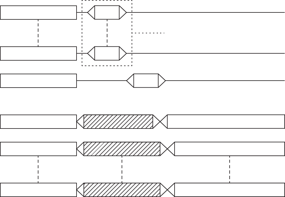
NOTE: Because timing is so
critical for flow control Graco recommends that users
provide a discrete input to minimize latency effects.
Input Register 10
Gun Trigger
Discrete Signal
10 1 0
ProMix PD2K
Gun Trigger State
Figure 12 Gun Trigger Timing (Network and Discrete
Signals Shown
INPUT REGISTER 11: Gun 2 Trigger
INPUT REGISTER 12: Gun 3 Trigger
INPUT REGISTER 13: Gun 4 Trigger
These registers are not used.
INPUT REGISTERS 14 – 21: DCS Command
Structure
SeeDynamic Command Description, page 47.
38 332564B


Operation Using a Programmable Logic Controller (PLC)
Network Input Data Map (Write/Read)
Network
Input ID
Modbus
Register
Parameter Name Data
Type
Units Range
0=No
1=PowerPump
s
2=RemoteStop
3 = Recipe Change
4 = Mix Fill
5=Mix
6=PurgeA
7=PurgeB
00 40156 System Mode Command uint32 NONE
8 = Standby
01 40158 Pump Flush Sequence #/Prime
Material#
uint32 NONE 1 - 5, 1 - 34
0=NoOP
1=Flus
hPump1
2=PrimePump1
3=FlushPump2
4=Pri
me Pump 2
5=FlushPump3
6=PrimePump3
7=Fl
ush Pump 4
02 40160 Flush/Prime Pump Command uint32 NONE
8=PrimePump4
03 40162 Mix (Pump 1) Control Set Point uint32 cc/min or
PSI
1 - 1600
04 40164 Pump 2 Control Set Point uint32 cc/min or
PSI
1-1600
05 40166 Pump 3 Control Set Point uint32 cc/min or
PSI
1 - 1600
06 40168 Pump 4 Control Set Point uint32 cc/min or
PSI
1 - 1600
0740170 Go to Recipe Number uint32 NONE 0,1-60
08 40172 Clear Active Alarm uint32 NONE 1 = Clear Active Alarm
09 40174 Job Complete uint32 NONE 1 = Trigger job complete
0 = Gun not triggered
10 40176 Gun 1 Trigger uint32 NONE
1 = Gun triggered
0 = Gun not triggered
11 40178 Gun 2 Trigger uint32 NONE
1 = Gun triggered
40 332564B

Operation Using a Programmable Logic Controller (PLC)
0 = Gun not triggered
12 40180 Gun3Trigger uint32 NONE
1 = Gun triggered
0 = Gun not triggered
13 40182 Gun4Trigger uint32 NONE
1 = Gun triggered
14 40184 Command Argument 0 uint32 NONE N/A
15 40186 Command Argument 1 uint32 NONE N/A
16 40188 Command Argument 2 uint32 NONE N/A
17 40190 Command Argument 3 uint32 NONE N/A
18 40192 Command Argument 4 uint32 NONE N/A
19 40194 Command Argument 5 uint32 NONE N/A
20 40196 CommandArgument6 uint32 NONE N/A
21 40198 DCS Command uint32 NONE See Command Table
These registers are not used. DCS Register
332564B 41
Operation Using a Programmable Logic Controller (PLC)
Operation Flow Charts
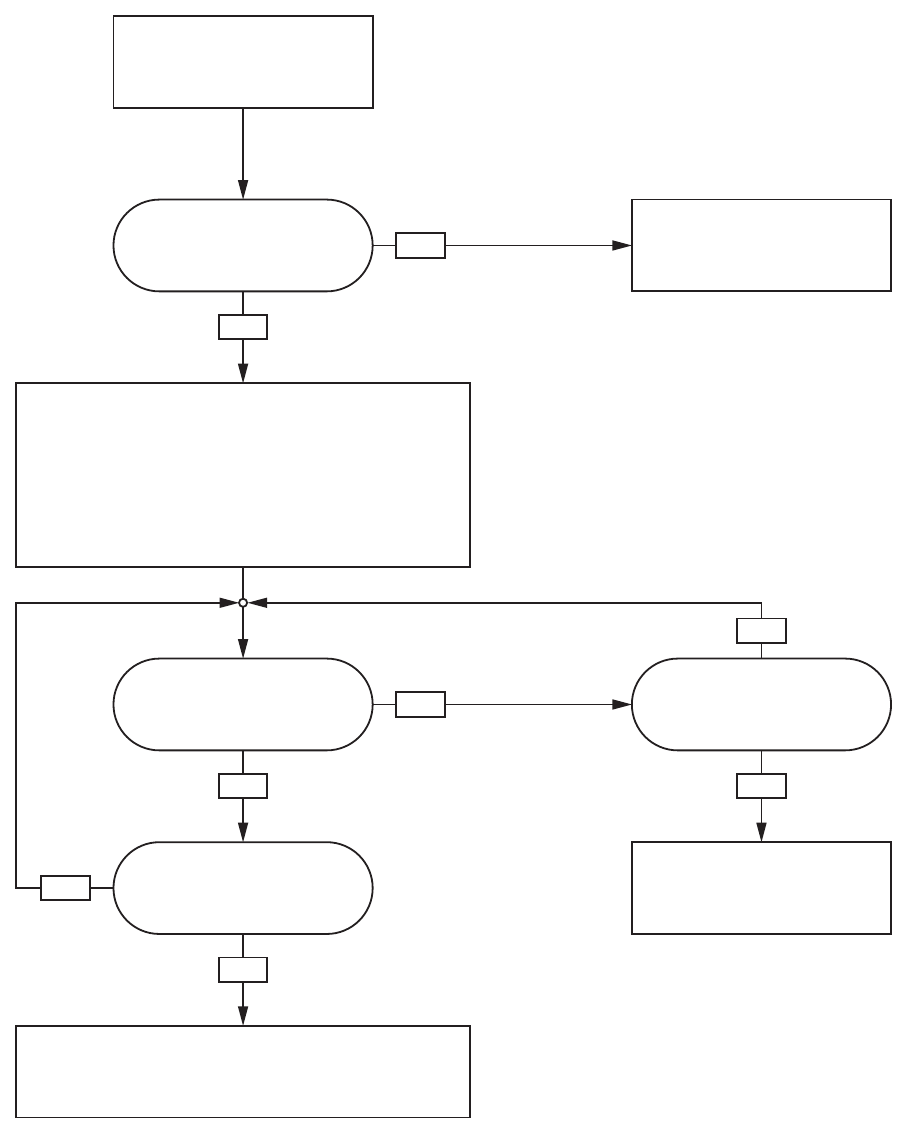
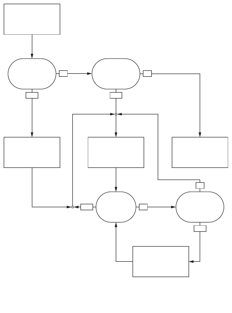
Purge Mode Sequence
YES
YES
YES YES
NO
NO
NO
NO
Purge A System Command
Write ‘6’ to Input Register 00
Is system in Standby or
Pumps Off?
Is solvent flow switch 1 ON?
Purge time expired?
System Mode = Standby: Mix Not Ready
(Output Register 00 = ‘13’)
System closes color solvent valve at remote stack.
Purge no flow timeout expired?
No solvent flow detected.
Generate alarm.
System Mode = Purge A
(Output Register 00 = ‘9’)
System opens color solvent valve at remote stack to allow
solvent flow through mix manifold and out gun.
Purge time set according to the flush sequence assigned to
material A in recipe.
No action taken.
Either pumps are currently
running or an alarm condition
exists.
NOTE: Purge B command works
similarly with the catalyst lines and
solvent flow switch 2.
42332564B
Operation Using a Programmable Logic Controller (PLC)
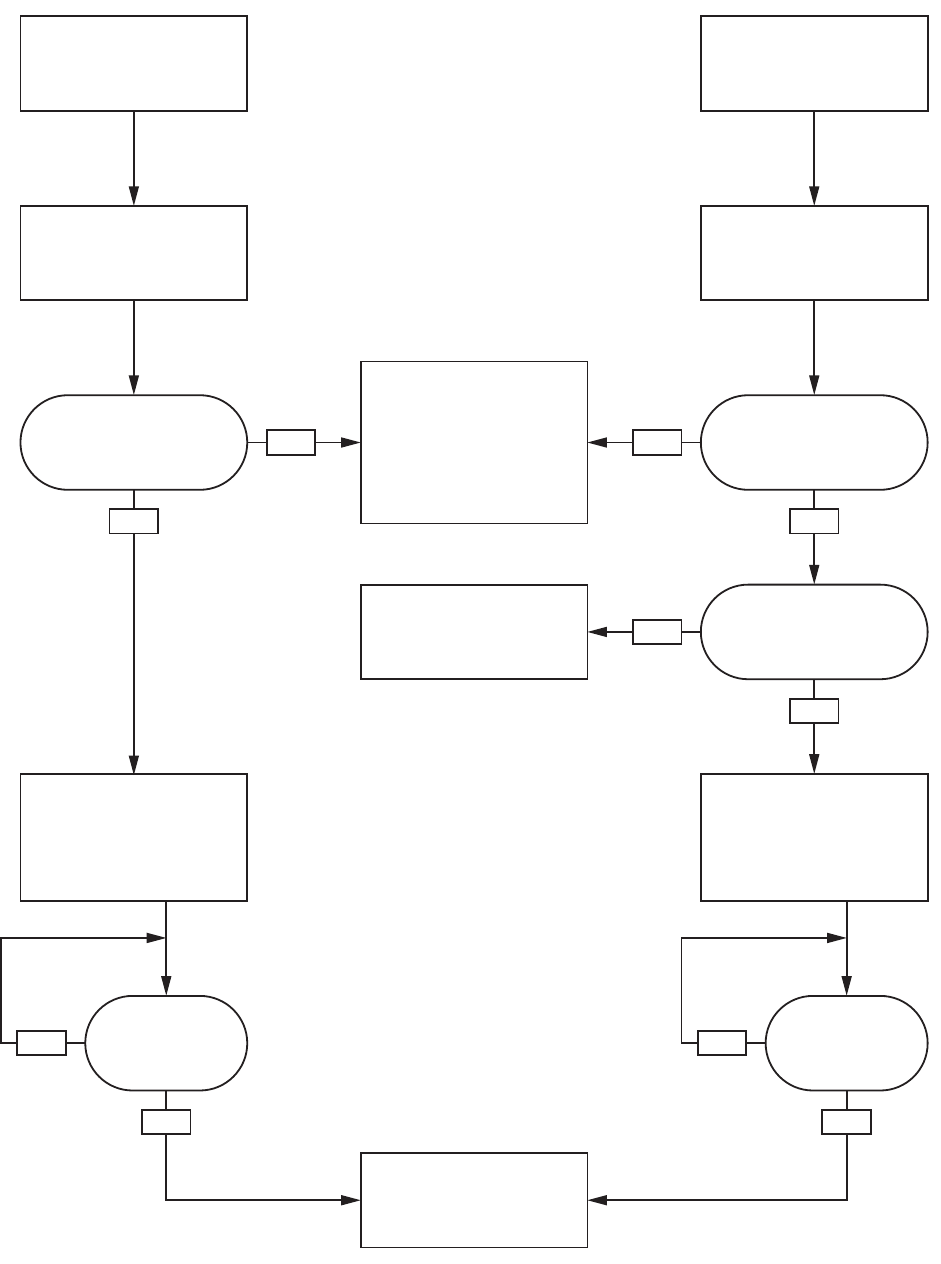
Inactive Pump Flush and Prime Sequences
YES YES
YES
YESYES
NO NO
NONO
NO
Write Flush Sequence #
(1-5) to Output Register 01
Write
Flush Pump Command
(1,3,5,7) to Input Register 02
Write
Prime Pump Command
(2,4,6,8) to Input Register 02
Is requested pump
status* = Standby?
(Output Register* = ‘1’)
Pump is flushed using
assigned sequence number.
Pump Status = Flushing
(Output Register* = ‘3’)
Pump is primed using
assigned material.
Pump Status = Priming
(Output Register* = ‘4’)
Pump is either Off or Busy
(Output Register* = ‘0’ or ‘2’)
Busy refers to a pump that is
currently involved in a mixing
operation. No action taken.
NOTE: Be sure to read to
appropriate Output Register*
for the desired pump status:
Register 01 - Pump 1
Register 02 - Pump 2
Register 03 - Pump 3
Register 04 - Pump 4
Is requested pump
status* = Standby?
(Output Register* = ‘1’)
Is selected material valid
for requested pump?
Invalid request.
No action taken.
Write Prime Material #
(1-34) to Output Register 01
Is Flush complete? Is Prime complete?
Pump is returned to Standby.
Pump Status = Standby
(Output Register* = ‘1’)
332564B 43
Operation Using a Programmable Logic Controller (PLC)
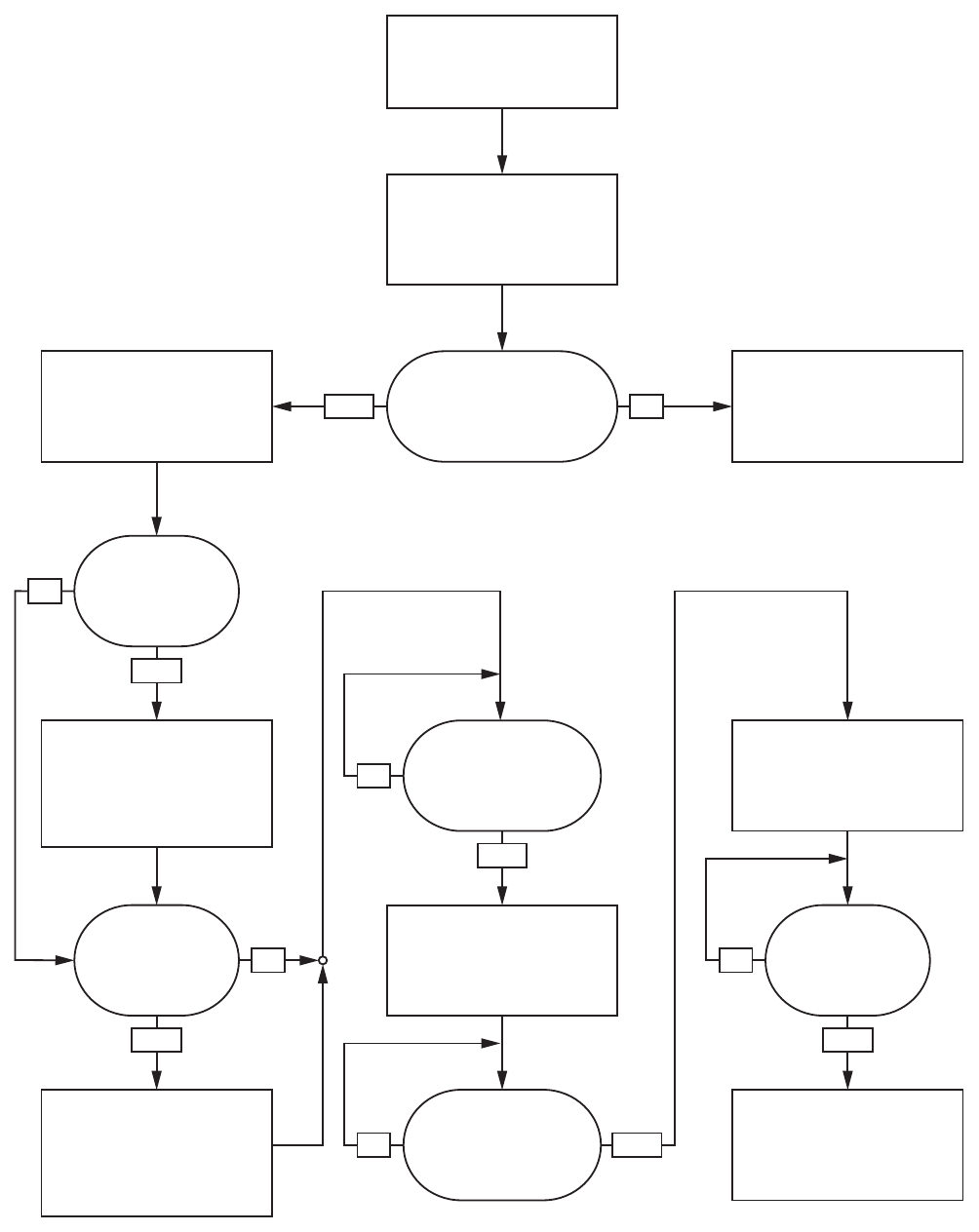
Color Change Sequence
YES
YES YES
NO
NO
NO
NO
YES NO
YES
YES
Write Goto Recipe Number
(0,1 - 60) to Input Register 07
Recipe Change System
Command
Write ‘3’ to Input Register 00
Is system in Standby
with no alarm conditions?
Is purge complete and
are pumps primed?
Is material filled out to
mix manifold?
Fill material out to mix
manifold.
System Mode = Recipe
Change: Fill
(Output Register 00 = ‘5’)
No action taken.
Either pumps are currently
running or an alarm condition
exists.
System Mode = Recipe
Change
(Output Register 00 = ‘2’)
Purge Material B out gun.
System Mode = Recipe
Change: Purge B
(Output Register 00 = ‘4’)
Pump will flush then prime.
Purge Material A out gun.
System Mode = Recipe
Change: Purge A
(Output Register 00 = ‘3’)
Pump will flush then prime.
Is Material B
changing?
Is Material A
changing? Is mix fill complete?
NO
Mix material out to gun.
System Mode = Mix Fill
(Output Register 00 = ‘6’)
System Mode = Standby:
Mix Ready
(Output Register 00 = ‘11’)
44332564B
Operation Using a Programmable Logic Controller (PLC)
Mixing Sequence
YESYES
NO
NO
YES
NO
NO
YES
Mix System Command
Write ‘5’ to Input Register 00
System Mode =
Standby: Fill Ready?
A recipe is loaded in the
pumps but not yet filled out
to the gun. Mixed material is
pumped out to the gun.
No action taken.
System is not in valid state
for mixing. Confirm pumps
are on, a recipe is loaded,
and there are no existing
alarm conditions.
System Mode = Mix
(Output Register = ‘7’)
Gun Trigger = ON? Mix Idle Timeout
expired?
Stem Mode =
Standby: Mix Ready?
No gun trigger signal for
longer than Mix Idle Timeout.
System Mode = Mix Idle
(Output Register = ‘8’)
NOTE: System will remain in
Mix mode until a STANDBY
command is issued or an alarm
condition exists.
332564B 45
Operation Using a Programmable Logic Controller (PLC)
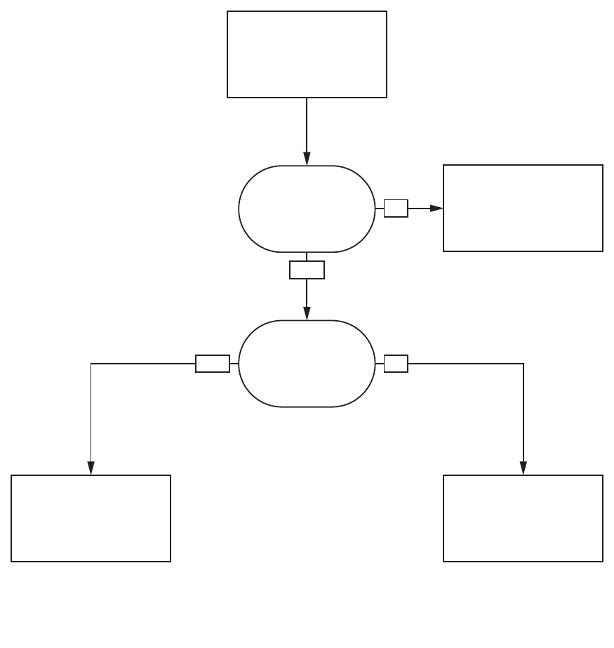
Alarm Clearing Sequence
NO
Clear Active Alarm
Write ‘1’ to Input Register 08
NOTE: If an alarm condition is
active the System Mode will either
be Pump Off or Standby: Alarm.
(Output Register 00 = ‘1’ or ‘14’)
No action taken.
Clear active alarm.
Clear most recent active
alarm.
Remaining alarm(s) still
active.
Is there an active
alarm?
Is there more than 1
active alarm?
YES
YES
NO
NOTE: If more than 1 active
alarm exists a repeated write
of ‘1’ to Input Register 08 is
required for each.
46 332564B
Operation Using a Programmable Logic Controller (PLC)
Network Communication - Dynamic Command Structure (DCS)
Dynamic Command Description
The Dynamic Command Structure (DCS) is used to 1) access data that requires some form of
argument(s) or 2) consolidate data that requires multiple registers. The DCS uses a static set of network
communication input and output registers (see Network Input Data Map (Write/Read), page 40 and
Network Output Data Map (Read Only), page 33.
Use the following sequence for the DCS.
1. Write the appropriate command arguments to INPUT REGISTERS 14 – 20. These commands may be
written sequentially or sent all at once.
2. Once all arguments have been passed, write the command ID to INPUT REGISTER 21.
3. TheProMixPD2Kwillrespondtoavalidcommandbywritinga2(Acknowledge) to OUTPUT REGISTER
28.
4. The ProMix PD2K will write appropriate return values to OUTPUT REGISTERS 29 – 36.
INPUT REGISTER 14
ProMix PD2K Inputs
(PLC Outputs)
ProMix PD2K Outputs
(PLC Inputs)
[arg_0]
INPUT REGISTER 14+n[arg_n]
INPUT REGISTER 21
OUTPUT REGISTER 28
OUTPUT REGISTER 29
OUTPUT REGISTER 29+n
[id]
ACK = 2
[rtn_0]
[rtn_n]
Can be written together
or sequentially.
Figure
13 Dynamic Command Structure Timing
332564B 47
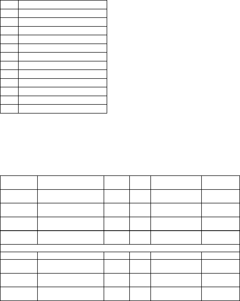
Operation Using a Programmable Logic Controller (PLC)
List of DCS Commands
Table 5 Dynamic Commands with Command ID
ID Command
0No OP
1 Write User ID
2WriteRecip
e
3Write Flush Sequence
4Write Fluid Control Mode
10 Read User ID
11 Read Recipe
12 Read Flush Sequence
13 Read Fluid Control Mode
14 Read JobInfo
15 Read Alarm Info
16 Read Event Info
Write User ID
The Write User ID command allows users to assign a User ID to a Job Log. See Usage Screen, page 64,for
more details on Job Log and User ID. The User ID can be up to ten ASCII characters in length and is packaged
as three little endian segments of ASCII characters. The return registers will echo the arguments received.
NOTE: The User ID character string must be terminated with a null character.
Example: Write a User ID of “John Doe” to the ProMix PD2K.
DCS Register Parameter Description Data
Type
Units Value Range
DCS
Command
Write User ID uint32 NONE 10-1
6
Argument 0 User ID characters [3:0]
(ASCII)
uint32 NONE 0x6E686F4A = [‘n’,
’h’, ’o’, ’J’]
N/A
Argument 1 User ID characters [7:4]
(ASCII)
uint32 NONE 0x656F4420 = [‘e’,
’o’, ’D’, ’ ‘]
N/A
Argument 2 User ID characters [9:8]
(ASCII)
uint32 NONE 0x0 = [null] N/A
Acknowledge Command Acknowledged uint32 NONE 2 = ACK 0-4
Return 0 User ID characters [3:0]
(ASCII)
uint32 NONE 0x6E686F4A N/A
Return 1 User ID characters [7:4]
(ASCII)
uint32 NONE 0x656F4420 N/A
Return 2 User ID characters [9:8]
(ASCII)
uint32 NONE 0x0 N/A
48 332564B

Operation Using a Programmable Logic Controller (PLC)
Write Recipe
The Write Recipe command allows users to configure an entire recipe remotely. See Recipe Screen, page 72,
for more details on recipes and recipe parameters. The return registers will echo the arguments received.
NOTE: The recipe must be enabled via the ADM before it can be loaded for mixing.
Example: Configure Recipe 6 for
Color = 2, Catalyst = 1, Color Flush Sequence = 2, Catalyst Flush Sequence
= 3, Mix Ratio Set Point = 1.50:1, and Potlife = 10 minutes.
DCS Register Parameter Description Data
Type
Units Value Range
DCS
Command
Write Recipe uint32 NONE 20-16
Argument 0 Recipe Number uint32 NONE 60-60
Argument 1 Material A uint32 NONE 20–30
Argument 2 Material B uint32 NONE 31 0, 31 – 34
Argument 3 Material A Flush Sequence uint32 NONE 21-5
Argument4 Material B Flush Sequence uint32 NONE 31-5
Argument 5 Mix Ratio Set Point uint32 NONE 150 = 1.50:1 0 - 5000
Argument 6 Potlife Time Set Point uint32 min 10 0 - 999
Acknowledge Command Acknowledged uint32NONE 2 = ACK 0-4
Return 0 Recipe Number uint32 NONE 60-60
Return 1 Material A uint32 NONE 20–30
Return 2 Material B uint32 NONE 31 0, 31–34
Return 3 Material A Flush Sequence uint32 NONE 21–5
Return 4 Material B Flush Sequence uint32 NONE 31–5
Return 5 Mix Ratio Set Point uint32 NONE 150 0- 5000
Return 6 Potlife Time Set Point uint32 min 10 0 - 999
332564B 49

Operation Using a Programmable Logic Controller (PLC)
Write Flush Sequence
The Write Flush Sequence command allows users to configure an entire flush sequence remotely. See
Flush Screen, page 73, for more details of flush sequence parameters. The return registers will echo the
arguments received.
Example: Configuring Flush Sequence 4 for Gun Purge Time = 10 sec, Initial Flush Volume = 125 cc, Final
Flush Volume = 250 cc, Wash Cycles = 1, Strokes per Cycle = 2.
DCS Register Parameter Description Data
Type
Units Value Range
DCS
Command
Write Flush Sequence uint32 NONE 30-16
Argument 0 Flush Sequence # uint32 NONE 41-5
Argument 1 Gun Purge Time uint32 sec 10 0 - 999
Argument 2 Initial Flush Volume uint32 cc 125 0 - 9999
Argument 3 Final Flush Volume uint32 cc 250 0 - 9999
Argument4 #WashCycles uint32 NONE 10-99
Argument 5 StrokesperWashCycle uint32 NONE 20-99
Acknowledge Command Acknowledged uint32 NONE 2 = ACK 0-4
Return0 Flush Sequence # uint32NONE 41-5
Return 1 Gun Purge Time uint32 sec 10 0 - 999
Return 2 Initial Flush Volume uint32 cc 125 0 - 9999
Return 3 Final Flush Volume uint32 cc 250 0 - 9999
Return 4 #WashCycles uint32 NONE 10-9
9
Return 5 Strokes per Wash Cycle uint32 NONE 20-99
50 332564B

Operation Using a Programmable Logic Controller (PLC)
Write Fluid Control Mode
The Write Fluid Control Mode command allows users to remotely change Fluid Control between ‘Flow’ and
‘Pressure’. See System Screen 5, page 71, for more details on Fluid Control mode. The return registers will
echo the arguments received.
NOTE: The Fluid Control mode should be changed only when the system is in Standby or when the pumps are
powered off. Do not change Fluid Control modes during a mix operation.
Example: Change to Flow Control mode.
DCS Register Parameter Description Data
Type
Units Value Range
DCS
Command
Write Fluid Control Mode uint32 NONE 40-16
0=FlowArgument 0 Fluid Control Mode uint32 NONE 0 = Flow Mode
1=Pressure
Acknowledge Command Acknowledged uint32 NONE 2 = ACK 0-4
0=FlowReturn 0 Fluid Control Mode uint32 NONE 0
1=Press
ure
Read User ID
The Read User ID command reads back the current User ID. See Usage Screen, page 64, for more details
on Job Log and User ID. The User ID can be up to ten ASCII characters in length and is packaged as three
little endian segments of ASCII characters. No arguments are required.
Example: Read User ID that is currently “John Doe”.
DCS Register Parameter Description Data
Type
Units Value Range
DCS
Command
Read User ID uint32 NONE 10 0 - 16
Acknowledge Command Acknowledged uint32 NONE 2 = ACK 0-4
Return 0 User ID characters [3:0]
(ASCII)
uint32 NONE0x6E686F4A = [‘n’,
’h’,’o’,’J’]
N/A
Return 1 User ID characters [7:4]
(ASCII)
uint32 NONE 0x656F4420 = [‘e’,
’o’, ’D’, ’ ‘]
N/A
Return 2 User ID characters [9:8]
(ASCII)
uint32 NONE 0x0 = [null] N/A
332564B 51
Operation Using a Programmable Logic Controller (PLC)
Read Recipe
The Read Recipe command returns all configured recipe parameters for a desiredrecipenumber. The
number of the recipe to be read is the only argument.
Example: Read Recipe 5 data as it is currently configured with Color = 3, Catalyst = 2 (32), Color Flush
Sequence = 1, Catalyst Flush Sequence = 4, Mix Ratio Set Point = 3.25:1, and Potlife = 35 min.
DCS Register Parameter Description Data
Type
Units Value Range
DCS
Command
Read Recipe uint32 NONE 11 0 - 16
Argument 0 Recipe # uint32 NONE 50-60
Acknowledge Command Acknowledged uint32 NONE 2 = ACK 0-4
Return 0 Recipe # uint32 NONE 50-60
Return 1 Material Auint32 NONE 3 0 - 30, 61
Return 2 Material B uint32 NONE 32 0, 31 - 34, 61
Return 3 Material A Flush Sequence uint32 NONE 11-5
Return 4Material B Flush Sequence uint32 NONE 41-5
Return 5 Mix Ratio Set Point uint32 NONE 325 0 - 5000
Return 6 Potlife Time Set Point uint32 min 35 0 - 999
Read Flush Sequence
The Read Flush Sequence command returns all configured parameters for a desired flush sequence. The
number of the flush sequence to be read is the only argument.
Example: Read Flush Sequence 1 as it is currently configured with Gun Purge Time = 20 sec, Initial Flush
Volume = 0 cc, Final Flush Volume = 500 cc, Wash Cycles = 2, and Strokes per Cycle = 1.
DCS Register Parameter Description Data
Type
Units Value Range
DCS
Command
Read Flush Sequence uint32 NONE 12 0 - 16
Argument 0 Flush Sequence # uint32 NONE 11
-5
Acknowledge Command Acknowledged uint32 NONE 2 = ACK 0-4
Return 0 Flush Sequence # uint32 NONE 11-5
Return 1 Gun Purge Time uint32 sec 20 0 - 999
Return 2 Initial Flush Volume uint32 cc 00-9999
Return 3 Final Flush Volume uint32 cc 500 0 - 9999
Return 4 #WashCycles uint32 NONE 20-99
Return 5 Strokes per Wash Cycle uint32 NONE 10-99
52 332564B

Operation Using a Programmable Logic Controller (PLC)
Read Fluid Control Mode
The Read Fluid Control Mode command is used to
read the current Fluid Control mode of the system
is currently operating under. No arguments are
required.
Example: Read Fluid Control as currently set to
Pressure mode.
DCS Register Parameter Description Data
Type
Units Value Range
DCS
Command
Read Fluid Control Mode uint32 NONE 13 0 - 16
Acknowledge Command Acknowledged uint32 NONE 2 = ACK 0-4
0=FlowReturn 0 Fluid Control Mode uint32 NONE 1 = Pressure
1=Pressure
332564B 53

Operation Using a Programmable Logic Controller (PLC)
Read Job Info
The Read Job Info command is used to access data from any of the most recent 200 job logs. The argument is
the
chronological index
of the job log, where 0 is the most recent job log and 199 is the 200th most recent.
The date is returnedasfour-bytepacketwitheachbyteholdingatwo-digitvaluefor(from MSB to LSB) year,
month, day, and day of the week (Monday = 01).
The time is returned as a three-byte packet with each byte holding a two-digit value. Starting from the MSB,
the first byte can be ignored, then hour, minute, and second.
NOTE: The argument is an index not a job number. The actual job number will, however, be one of the
returned parameters. These records will match what is reported on the Jobs screen of the ADM.
(See Usage Screen, page 64, for more details on Job Log)
Example: Read back the most recent job log, job 25, which ran recipe 2 for a totalof1234cc’sofmaterial
under User ID “John Doe”. The job was logged on Thursday May 29, 2014 at 11:22:14 AM.
DCS Register Parameter Description Data Type Units Value Range
DCS
Command
Read Job Info uint32 NONE 14 0 - 16
Argument 0 Job Index uint32 NONE 00–199
Acknowledge Command
Acknowledged
uint32 NONE 2 = ACK 0-4
Return 0Job Dateuint32 [YY:MM:DD-
:DW]
0x0E051D04 =
[14:05:29:04]
N/A
Return 1 Job Time uint32 [xx:HH:MM-
:SS]
0x0B160E =
[11:22:14]
N/A
Return 2 Job Number uint32 NONE 25 0 - 9999
Return 3 Recipe # uint32 NONE 20-60
Return 4 A+B Volume uint32 cc 1234 N/A
Return 5 User ID [3:0] (ASCII) uint32 NONE 0x6E686F4A = [‘n’,
’h’, ’o’, ’J’]
N/A
Return 6 User ID [7:4] (ASCII) uint32 NONE 0x656F4420 = [‘e’,
’o’, ’D’ ‘ ’]
N/A
Return 7 User ID [9:8] (ASCII) uint32 NONE 0N/A
54 332564B

Operation Using a Programmable Logic Controller (PLC)
Read Alarm Info
The Read Alarm Info command allows remote access to any of the last 200 alarms logged by the ProMix
PD2K. The argument is the
chronological index
of the alarm log, where 0 is the most recent alarm and 199 is
the 200th most recent.
The date is returned as a four-byte packet with each byte holding a two-digit value for (from MSB to LSB) year,
month, day, and day of the week (Monday = 01).
Thetimeisreturnedasathree-bytepacketwitheachbyteholdingatwo-digit value. Starting from the MSB,
the first byte can be ignored, then hour, minute, and second.
The alarm code is a four-character little endian ASCII string
See System Errors, page 88, for more details on these Event Types.
An example decoding algorithm is provided below.
Example: Read back the second most recent alarm, which was a Position Pump 1 (DK01) recorded on
Tuesday June 3, 2014 at 8:11 AM.
DCS Register Parameter Description Data
Type
Units Value Range
DCS
Command
Read Alarm Info uint32 NONE 15 0 - 16
Argument 0 Alarm Index uint32 NONE 10-199
Acknowledge Command Acknowledged uint32 NONE 2 = ACK 0-4
Return 0Alarm Date uint32 [YY:MM:DD:DW] 0x0E060302 =
[14:06:03:02]
N/A
Return 1 Alarm Time uint32 [xx:HH:MM:SS] 0x080B0B =
[08:11:11]
N/A
Return 2 Alarm Code Char[3:0] uint32 NONE 0x31304B44 = [‘1’,
’0’, ’K’, ’D’]
N/A
Example ASCII Character String Decode Algorithm:
character_str[0] = Return_2 & 0xFF;
character_str[1] = (Return_2 >> 8) & 0xFF;
character_str[2] = (Return_2 >> 16) & 0xFF;
character_str[3] = (Return_2 >> 24) & 0xFF;
character_str[4] = ‘\0’;
332564B 55

Operation Using a Programmable Logic Controller (PLC)
Read Event Info
The Read Event Info command allows remote access to any of the last 200 events logged by the ProMix
PD2K. The argument is the
chronological index
of the events log, where 0 is the most recent event and
199 is the 200th most recent.
Thedateisret
urned as a four-byte packet with each byte holding a two-digit value for (from MSB to LSB) year,
month, day, and day of the week (Monday = 01).
The time is returned as a three-byte packet with each byte holding a two-digit value. Starting from the MSB,
the first byte can be ignored, then hour, minute, and second.
The event code is a four-character little endian ASCII string.
The example decoding algorithm provided above for the Alarm Code may be used for Events equivalently.
Example: Read back the fifth most recent event, which was a Setup Value(s) Changed (EC00) recorded
on Tuesday June 3, 2014 at 8:11 AM.
DCS Register Parameter Description Data
Type
Units Value Range
DCS
Command
Read EventInfo uint32 NONE 16 0 - 16
Argument 0 Event Number uint32 NONE 40-199
Acknowledge Command
Acknowledged
uint32 NONE 2 = ACK 0-4
Return 0 Event Date uint32 [YY:MM:DD-
:DW]
0x0E060302 =
[14:06:03:02]
N/A
Return1 Event Time uint32[xx:HH:MM:SS] 0x080B0B =
[08:11:11]
N/A
Return 2 Event Code Char[3:0] uint32 NONE 0x30304345 = [‘0’,
’0’, ’C’, ’E’]
N/A
56 332564B
Operation Using a Programmable Logic Controller (PLC)
Flow Control System
Overview
Flow control is an optional feature that precisely
regulates the flow of material to an automatic spay
device, to help ensure adequate coverage and avoid
sags or runs in the finish coat. The ProMix PD2K
system can control fluid flow by directly controlling
the proportioning pumps. The pumps accurately
dispense a fixed volume of fluid during each stroke.
For this reason, the flow rate of a given pump is
directly proportional to the velocity of the pump. As
long as the gun is open and the system is stable, flow
control is the most effective method for controlling
flow rate.
The flow control system relies on two main inputs for
controlling flow rate: Gun Trigger and Control Set
Point.
NOTE: These inputs are timing critical. Graco
recommends that users wire them discretely to the
controller.
Alternatively these two inputs can be
driven by the network communications, but latency
could be an issue for systems requiring precise
timing.
See System Screen 5, page 71, for more details on
configuring these options for ‘Discrete’ or ‘Network’.
NOTE: Flow control cannot be selected with a
manual gun system.
Normal Flow Control
The ProMix PD2K will directly control the speed of
the pump(s) to the programmed flow control set point
to maintain accurate flow rate and ratio. The flow
control set point is set by Network Communications
or the Discrete Input.
The system is considered to be stable when the
pressure readings do not fluctuate and the flow rate
is maintained. While the system is considered stable
it will store (“learn”) the associated pump pressures
to a table that is used if the gun trigger signal is lost
or removed.
Pressure Control
When the gun trigger signal is removed the system
automatically switches to pressure control mode to
avoidoverpressurizingthefluidlinesandtoallow
smooth transition to flow control if the gun trigger
signal returns. It also works to maintain a consistent
flow rate even though it has transitioned to pressure
control mode if the gun trigger signal is inadvertently
lost.
Gun On/Off Prediction
The pressure table also is used to predict if the gun
has been turned on or off (without a change to the
gun trigger input). The flow control system continually
monitors the desired outlet pressure compared to the
actual outlet pressure. If the actual pressure remains
50% higher than the desired pressure for longer than
10msec, then the system predicts that the gun trigger
has been released. If the actual pressure drops
below the desired pressure longer than 10msec, then
the system predicts that the gun has been triggered.
The gun on/off prediction is used in the flow control
algorithmtopreventthefluidpressurefrombecoming
too high or too low due to a system disturbance. For
example, if a gun off prediction occurs while the gun
trigger input is high, the system will begin to control
to the pressure value last stored in the pressure table
for the current flow set point.
System Startup and Defaults
The pressuretableisstoredinvolatilememory,so
the table values will be lost after a power cycle of the
ProMix PD2K controller. This issue is not significant
because the system generally is able to recalculate
new pressure table values within a few seconds
(depending on the stability of the fluid system).
332564B 57
Run Mode Screens
RunModeScree
ns
NOTE: Selection fields and buttons that are
grayed-out on the screens are not currently active.
Opening Screen
At power up, the Graco logo will display for
approximately 5 seconds, followed by the Home
screen.
Figure 14 Opening Screen
Home Screen
The Home screen displays the current status of the
system. The following table details the information
shown.
To view pump flow rates and pressures
(as shown), select “Diagnostic Mode” on
System Screen 1, page 67.
Figure 15 Home Screen, in Mix Mode with
Diagnostics On
58 332564B

Run Mode Screens
Home Screen Key
Key Description Details
A Date and Time See Advanced Screen 1, page 82,toset.
B Menu Bar Run Screens. Use left and right arrow keys to scroll through the
different Run screens:
• Home (shown in Diagnostic Mode)
• Spray (see Spray Screen, page 62)
• Fill (see Fill Screen, page 63), available only if manual override
is enabled on System Screen 5, page 71.
• Usage (see Usage Screen, page 64)
•Jobs(seeJobs Screen, page 65)
•Errors(seeErrors Screen, page 65)
• Events (see Events Screen, page 65)
System Status: Displays the current mode of operation:
C Status Bar
•PumpOff
• Standby
•Startup
•Mix
• Fill
• Purge
• Shutdown
• Change Recipe
•Idle
• Prime Pump
• Calibrate
•StallTest
• Maintenance Test
DError Status Displays any active error code.
332564B 59
Run Mode Screens
Key Description Details
E Pump Animation and
Diagnostic Information
FPump Number (1–4)
G Material (A or B)
HAvailable Colors
JPump Inlet Color
L Pump Flow Rate
MPump OutletColor
NPump Outlet Pressure
P Pump Indicator Light
• Clear = power off
• Yellow = standby
•Green=active
SSolven
tFlowRate Shows solvent flow rate, if a solvent meter is attached.
Shows mixed material in the spray device and displays active
recipe at the spray device. Gun animation changes to show:
TSpray Device Animation
•
(Mix Fill)
•
(Mix With Gun Triggered)
•
(Recipe Standby)
•
(Purge)
•
• (Solvent Standby)
•(Mix With
Gun Not Triggered)
60 332564B
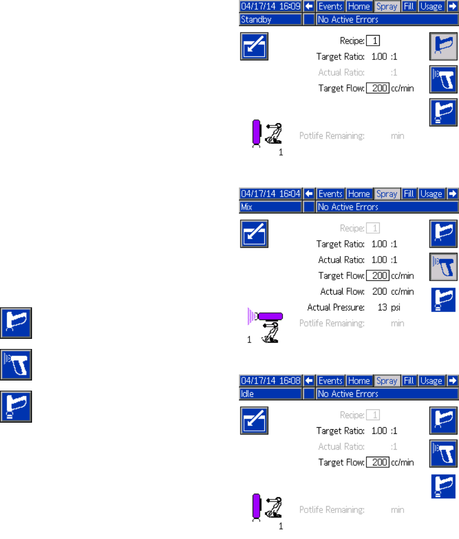
Run Mode Screens
Spray Screen
NOTE: In normal operating mode, controlled by a
PLC, the Spray Screen is display only. No changes
can be made. This section provides information
about the Spray Screen if manual override is enabled
on System Screen 5, page 71. The screens show a
system in manual override mode.
The Spray screen includes the following information:
• Active Recipe (can be changed on this screen)
• Target Ratio
• Actual Ratio
• Target Pressure (if Pressure Mode is selected on
System Screen 5) or Target Flow (if Flow Mode is
selected). Target pressure or flow can be changed
on this screen).
• Actual Pressure
• Actual Flow
• Potlife Remaining
• Gun Animation
In addition, the Spray screen includes three soft keys:
Press to put the system in
Standby.
Press to spray mixed material.
Press to purge the gun.
Figure 16 Spray Screen, in Standby Mode
Figure 17 Spray Screen, in Mix Mode
Figure 18 Spray Screen, in Idle Mode
62 332564B
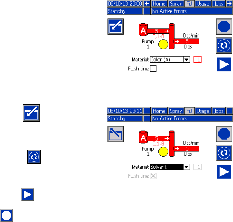
Run Mode Screens
Fill Screen
NOTE: This screen is visible only if manual override
is enabled on System Screen 5, page 71.
The Fill screen displays the following information for
the pump assigned to the current color:
• Material. Select Color (A), Catalyst (B), or Solvent.
The pump animation at the top of the screen will
show the selected material.
• Flush Line (only for systems with color change).
Select this box if you want to flush the specified
material line. The system uses flush sequence 1.
To prime the pumps and fill the lines, first read
Prime and Fill the System, page 20.
1. Press the Edit softkey to open the screen
for editing.
2. Select Color (A).
3. If the selected material is not already loaded,
press the Prime softkey . The system will
prime Color (A) into the selected pump through
the selected color valve and out the outlet dump
valve.
4. Press the Fill softkey . The system will
attempt to fill the Color (A) lines until the user
presses Stop . Trigger the gun into a waste
container.
5. Repeat for Catalyst (B).
Figure 19 Fill Screen, Color (A) Selected
Figure 20 Fill Screen, Solvent Selected
332564B 63
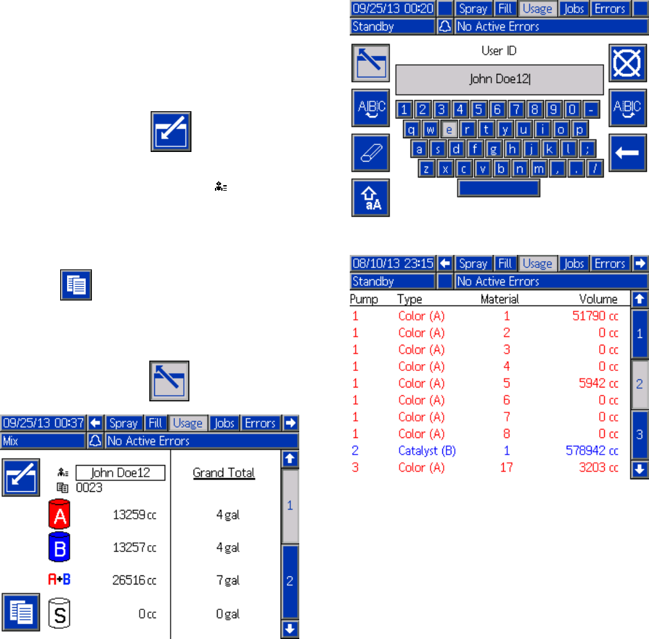
Run Mode Screens
Usage Screen
The first Usage screen displays the current job usage
and grand total usage of component A, B, A+B,
and solvent (S). Edits may be made only if manual
override is enabled on System Screen 5, page 71.
The second Usage screen displays the total volume
pumped for all available materials.
1. Press the Edit softkey to open the screen
for editing.
2. To enter or change the User ID ( ), select the
field to open the User ID Keyboard screen,
and enter the desired name (10 characters
maximum).
3. To log the current job, press the Job Complete
softkey . This will clear the current usage
fields and increment to the next job number.
The Grand Totals cannot be cleared. See the
Jobs Screen, page 65, to review past jobs.
4. Press the Edit softkey to close the screen.
Figure 21 Usage Screen
Figure 22 User ID Keyboard Screen
Figure 23 Usage Log
64 332564B
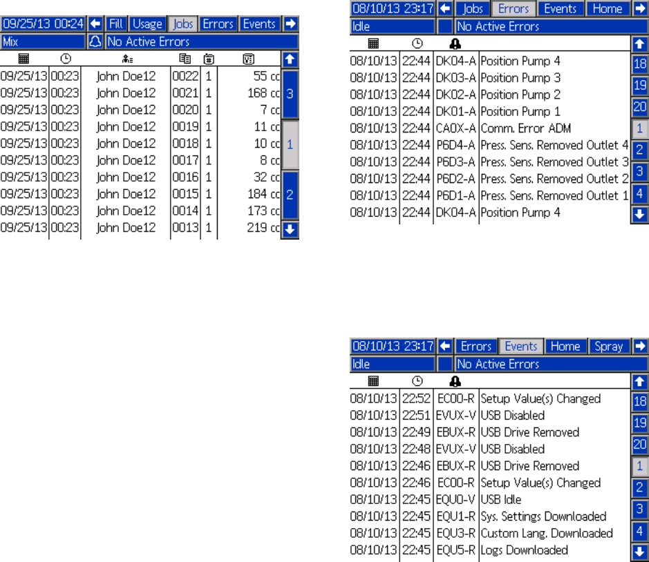
Run Mode Screens
Jobs Screen
The Jobs screen displays the 200 most recent job
numbers, recipes, and A+B volumes in a log, with
date, time, and User ID.
Figure 24 Jobs Screen
Errors Screen
The Errors screen displays the 200 most recent Error
Codes in a log, with date, time, and description.
Figure 25 Errors Screen
Events Screen
The Events screen displays the 200 most recent
Event Codes in a log, with date, time, and description.
Figure 26 Events Screen
332564B 65
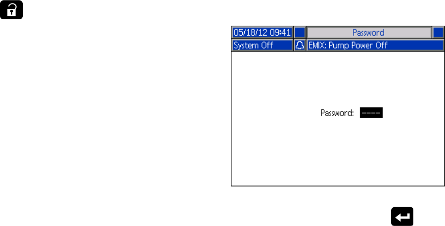
Setup Mode Screens
SetupModeScr
eens
Press on any Run screen to enter the Setup
screens.
NOTE: Selection fields and buttons that are
grayed-out on the screens are not currently active.
If the system has a password lock, the Password
screen displays. See Password Screen, page 66.
Password Screen
Figure 27 Password Screen
Enter the 4 digit password, then press .System
screen 1 will open, allowing access to the other
Setup screens.
Entering an incorrect password clears the field.
Reenter the correct password.
To assign a password, see
Advanced Screen 1, page 82.
66 332564B
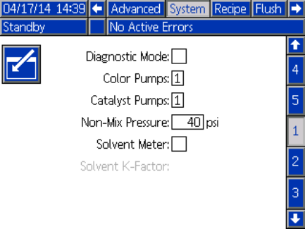
Setup Mode Screens
System Screen 1
System screen 1 includes the following fields which
define your system.
Figure 28 System Screen 1, During Standby
Diagnostic Mode
Select this box to display flow rate and pressure for
eachpumpontheHome Screen, page 58.
Color Pumps
Enter the number of color pumps in your system.
Catalyst Pumps
Enter the number of catalyst pumps in your system.
Non-Mix Pressure
Enter a lower pressure for use when not mixing and
spraying (for example during fill or flushing).
NOTE: Low pressure systems may be set 100 psi
(0.7 MPa, 7 bar) lower than target pressure; high
pressure systems may be set 300 psi (2.1 MPa, 21
bar) lower than target pressure.
Solvent Meter
Select this box if your system uses a solvent meter.
The Solvent K-Factor field will then become active.
SolventK-Factor
Enter the solvent meter K-Factor.
332564B 67
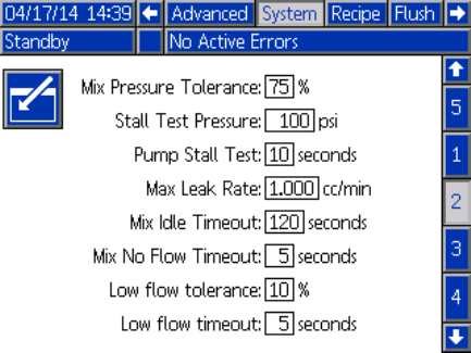
Setup Mode Screens
System Screen 2
System screen 2 sets the following system operating
parameters.
Figure 29 System Screen 2, in Standby Mode
Mix Pressure Tolerance
The pressure of one component must be within
a percentage (±) of the pressure of the other
component during spray or mix. Set the desired Mix
Pressure Tolerance in this field. The default is 75%.
Stall Test Pressure
Set the minimum stall test pressure. The setting
should be approximately 50 psi (0.35 MPa, 3.5 bar)
higher than the highest inlet pressure.
Pump Stall Test
Set the duration for the pump stall test. See
Calibrate Screen 1, page 77.
Maximum Leak Rate
Enter the maximum allowable leak rate for a pump
stall test.
Mix Idle Timeout
The Gun Trigger Input signals that the device is
triggered. If you are not using a gun trigger signal,
the system does not know if the spray device is
spraying. If a pump failed you could spray pure resin
or catalyst without knowing. This should be caught
by the Mix No Flow Timeout; the default is 5 seconds.
The Mix Idle Timeout will trigger Idle mode, which
will run a pump stall test to check for leaks, then put
the pumps in Standby (holding their current position)
after the designated period of time. Enter the desired
Mix Idle Timeout in this field.
See Digital Inputs, page 25.
Mix No Flow Timeout
The Gun Trigger Input signals that the gun is
triggered. If the Gun Trigger Input indicates that the
gun is triggered, but there is no fluid flow through a
pump, you could spray pure resin or catalyst without
knowing. The Mix No Flow Timeout will cause the
system to shutdown after the designated period of
time. The default is 5 seconds. Enter the desired
shutdowntimeinthisfield.
See Digital Inputs, page 25.
Low Flow Tolerance
This field is active in systems set to Flow Control.
The system will detect if the flow rate falls below a
designated percentage of the target flow rate. Set
that percentage in this field. For example, you might
want the system to time out if it detects a flow rate
that is 10 percent of the target, rather than waiting
until a no flow timeout occurs.
Low Flow Timeout
The low flow timeout causes the system to shut down
after the designated period of time if the flow rate
continues to be at or below the low flow tolerance set
in the previous section. The default is 5 seconds.
Enter the desired shutdown time in this field.
68 332564B
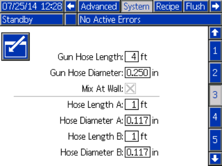
Setup Mode Screens
System Screen 3
System screen 3 sets the following system operating
parameters.
Figure 30 System Screen 3
Gun Hose Length
Enter the length of the hose from the remote mix
manifold to the spray device.
Gun Hose Diameter
Enter the diameter of the hose from the remote mix
manifold to the spray device. The minimum diameter
is 1/8 in. (3 mm).
Mix At Wall
This field is always enabled in Automatic systems.
Hose Length and Diameter
Enter the length and diameter of the hose from the
remote color stack to the remote mix manifold, for
both A and B hoses.
332564B 69
Setup Mode Screens
System Screen 4
System screen 4 sets the following system operating
parameters.
Figure 31 System Screen 4
Gateway ID
Select the desired Gateway ID from the dropdown
menu.
Enable
Uncheck Enable while setting the IP Address, Subnet
mask, Gateway, DNS1 or DNS2. When the settings
are loaded, check the Enable box to write the new
settings to the selected Gateway.
Checkthisb
ox to enable the selected Gateway so
that the PLC can communicate with it.
DHCP
Select this box if your system has a Dynamic Host
ConfigurationProtocol(DHCP).Thisprotocolassigns
unique IP addresses to devices, then releases and
renews these addresses as devices leave and rejoin
the network. If selected, the IP Address, Subnet, and
Gateway fields will not be editable and will display
the addresses supplied by the DHCP.
TCP/IP
Use the remaining fields to set the IP address, subnet
mask, Gateway, DNS1, and DNS2.
70 332564B
Setup Mode Screens
System Screen 5
System screen 5 sets the following system operating
parameters.
Figure 32 System Screen 5
Fluid Control
Select the desired operating mode (pressure or flow),
using the pull-down menu.
•InPressure Mode, the motor will adjust the pump
speed to maintain the fluid pressure set by an
external control device.
•InFlow Mode, the motor will maintain a constant
speed to maintain the target flow rate set by an
external control device.
Manual Override
Check this box to give users system control at the
ADM. Leave the box unchecked if all system settings
are controlled through a PC, PLC, or other networked
device.
Gun Trigger Signal
Select the format of the signal indicating whether the
spray device is triggered.
• Discrete — the signal is sent via a direct,
hard-wired connection
•Network—th
esignalissentviaaPC,PLC,or
other networked device.
Flow Control (Setpoint Signal)
Select the format of the signal that indicates system
flow rate or pressure.
• Discrete — the signal is sent via a direct,
hard-wired connection. This selection will make
the Max Rate field active.
• Network — the signal is sent via a PC, PLC, or
other networked device.
Stepup Gain and Stepdown Gain
These fields are active only for systems set to flow
control on System Screen 5. Enter a value from 1 to
100tooptimizesystemresponsetimetoachange
in fluid flow setpoint. Use the Stepup Gain field for
increases in fluid flow setpoint. Use the Stepdown
Gain field for decreases in fluid flow setpoint.
332564B 71
Setup Mode Screens
Recipe Screen
Figure 33 Valid Recipe Screen
Recipe
Enter the desired recipe number (1-60).
Recipe 0
UseRecipe0toflushthesystem.
•If a recipe (1–60) is loaded: Select Recipe 0 to flush
the previously active pumps and purge the gun.
•If Recipe 0 or 61 is loaded: Select Recipe 0 to
flush all pumps and purge the gun.
Enabled
Selecting “Enabled” makes the selected recipe
accessible from the Spray screen on the ADM or to
the PLC.
Note: Recipe 0 is always enabled.
Color (A) Valve
Enter the desired color valve number (1-30).
NOTE: If you enter a number which is not valid in
your system configuration, the field will be highlighted
and the recipe becomes invalid. For example, if your
configuration has 8 color valves and you enter 30,
the field will appear as shown below.
Figure 34 Invalid Recipe Screen
Catalyst (B) Valve
Enter the desired catalyst valve number (1-4).
NOTE: If you enter a number which is not valid in
your system configuration, the field will be highlighted
and the recipe is invalid. For example, if your
configuration has 1 catalyst valve and you enter 4,
the field will be highlighted and the recipe is invalid.
Flush Sequence
Enter the desired flush sequence (1-5) for the color
(A) valve and the catalyst (B) valve. The gun purge
time for each material depends on the flush sequence
assigned to each. See Flush Screen, page 73.If
materials A and B require different purge times,
assign separate flush sequences. Set the necessary
gun purge time for each. For hard to flush colors,
select a longer sequence. 1 is the default, and should
be designated for the longest, most thorough flush
duration.
Mix Ratio
Enter the desired mix ratio (0 to 50.0):1.
Potlife Time
Enter the potlife time (0 to 999 minutes). Entering
0 disables this function.
72332564B
Setup Mode Screens
Flush Screen
Figure 35 Flush Screen
Flush Number
Enter the desired flush sequence (1-5). For hard
to flush colors, select a longer sequence. 1 is the
default, and should be designated for the longest,
most thorough flush duration.
Gun Purge Time
Enter the spray device purge time (0 to 999 seconds).
Initial Flush
Enter the initialflushvolume(0to9999cc).
Final Flush
Enter the final flush volume (0 to 9999 cc).
Wash Cycles
AWashCycleactivates the pump with the valves
closed, to use pumping motion to thoroughly clean
the pump. Enter the desired number of wash cycles
(0 to 99). Entering a number will make the Strokes
per Cycle field active.
Strokes per Wash Cycle
Enter the desired pump strokes per wash cycle (0
to 99). Default is 1.
332564B 73
Setup Mode Screens
Pump Screen 1
NOTE: Your system may include 2, 3, or 4 pumps.
Information for each pump is accessible under a
separate tab in the menu bar at the top of the screen.
Select the tab for the desired pump. Each pump has
three screens. Only the screens for Pump 1 are
shown here, but the same fields appear on all.
Pump screen 1 includes the following fields which
define the pump.
Figure 36 Pump Screen 1
Pump Size
Select 35cc or 70cc, as appropriate.
Inlet Pressure
Select one of the following:
• Disabled
• Monitor, to track inlet pressure
Select Color Change
Select this box if your system uses color change.
Materials
Enter the number of materials used in your system.
Each color change module controls 8 colors.
Hose Length
Compute the length of the hoses from the supply
stack to the pump and from the pump to the outlet
stack. Enter the total length.
Hose Diameter
Enter the diameter of the supply and output hoses.
Available Colors
The module displays the number of colors available
in your system. This field is not editable.
74332564B
Setup Mode Screens
Pump Screen 2
Pump screen 2 sets the pressure transducer settings
for the pump.
Figure 37 Pump Screen 2, Default Settings Enabled
Figure 38 Pump Screen 2, Default Settings Disabled
Default Settings Selected
When the “Use Default Settings” box is selected,
default settings are used for the calibration values,
and the fields are grayed out.
Default Settings Not Selected
When the “Use Default Settings” box is not selected,
the following calibration values must be entered.
Invalid values will be over-ridden and the system will
automatically select the default settings.
•InletOffs
et Factor: This field is only used if Inlet
Pressure inPump Screen 1, page 74 is set to
Monitor; it is grayed out if set to Disabled. The
valid range is -01.20 to +01.20 mV/V.
•InletSen
sitivity Factor: This field is only used if
Inlet Pressure in Pump Screen 1, page 74 is set
to Monitor; it is grayed out if set to Disabled. The
valid range is 18.80 to 21.20 mV/V.
•OutletO
ffset Factor: The valid range is -01.20 to
+01.20 mV/V.
•OutletS
ensitivity Factor: The valid range is 18.80
to 21.20mV/V.
332564B 75
Setup Mode Screens
Pump Screen 3
Pump screen 3 sets the pressure alarm limits for the
pump.
When Inlet Pressure in Pump Screen 1, page 74 is
set to Disabled, the inlet limit fields are grayed
out and only the outlet limit fields are active. See
Pressure Alarm and Deviation Limits, page 76.
Figure 39 Pump Screen 3, Pressure Monitoring
Disabled
When Inlet Pressure in Pump Screen 1, page 74 is
set to Monitor, all fields are active. See
Pressure Alarm and Deviation Limits, page 76.
Figure 40 Pump Screen 3, Pressure Monitoring
Enabled
Pressure Alarm and Deviation Limits
Inlet fields are only active if Inlet Pressure
in Pump Screen 1, page 74 is set to Monitor; they
are grayed out if set to Disabled. Outlet fields are
active at all times.
• Alarm and Deviation ranges are 0-300 psi for
low pressure systems, and 0-1500 psi for high
pressure systems.
• Setting to 0 will disable the alarm. The Inlet Alarm
High and Outlet Alarm High cannot be disabled.
• Alarms and Deviations will display when the inlet
or outlet pressure drops below the low limit or
exceeds the high limit.
76 332564B
Setup Mode Screens
Calibration Screens
Calibrate Screen 1
Calibrate Screen 1 initiates a pump pressure check
(stall test) for the selected pump. During the test, the
Stall Test screen will appear.
The pump and lines must be primed with color
or catalyst before doing the stall test. See
System Screen 2, page 68 to set test parameters.
See Pump Pressure Check, page 84 for complete
test instructions.
To initiate the test, press the Pressure Check
button for the desired pump. The pump will build
pressure in the line to a minimum of the Stall Test
Pressure. The pump will then move to the center
stroke position and stall test the upstroke, followed
by the downstroke.
NOTE: TheLastPassedlogcanonlyberesetby
successfully completing the test.
The screen displays the number of days since the
last stall test was passed for each pump.
Figure 41 Calibrate Screen 1
Figure 42 Stall Test Screen
332564B 77
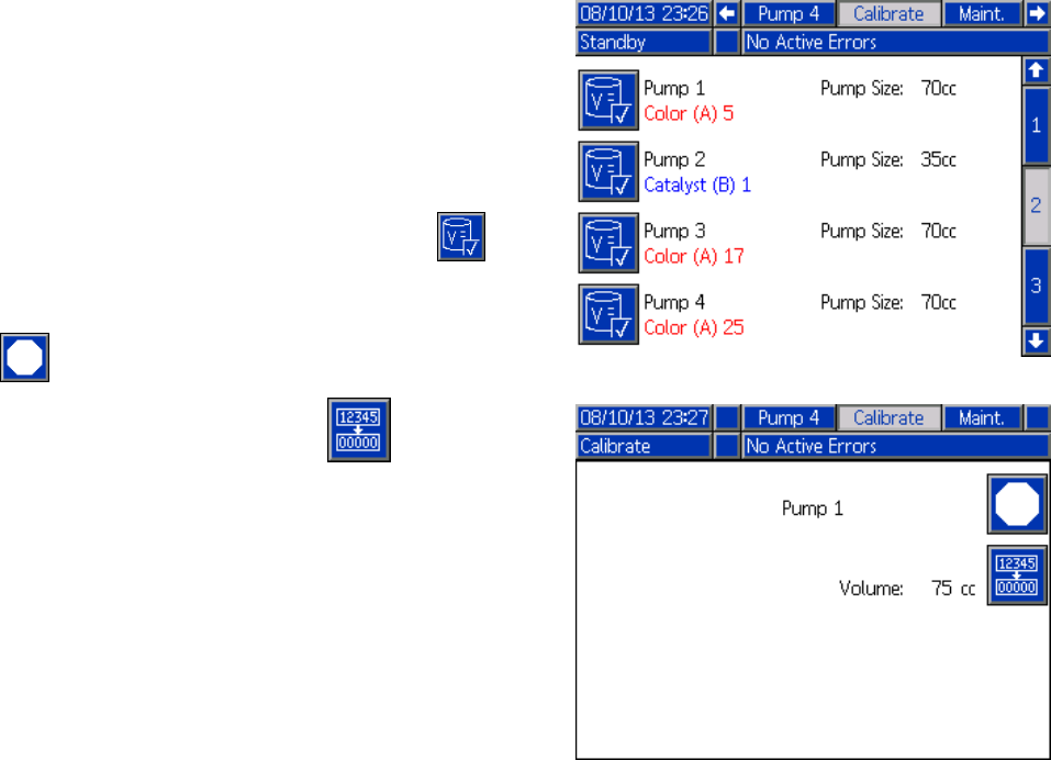
Setup Mode Screens
Calibrate Screen 2
Calibrate Screen 2 initiates a volume test for the
selected pump. During the test, the Volume Check
screen will appear.
The pump and lines must be primed with color
or catalyst before doing the Volume Check. See
Pump Volume Check, page 85 for complete test
instructions.
To initiate the test, press the Volume Check
button for the desired pump.
The screen displays the volume dispensed. Press
to end the test.
Press and hold the Reset button for 1-2
seconds to reset the volume counter.
Figure 43 Calibrate Screen 2
Figure 44 Volume Check Screen
78 332564B
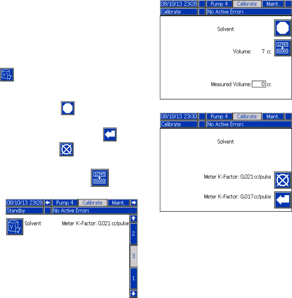
Setup Mode Screens
Calibrate Screen 3
Calibrate Screen 3 initiates a calibration of an
accessory solvent meter. During the test, the Volume
Verification screen will appear.
The meter and lines must be primed with
solvent before doing the calibration. See
Solvent Meter Calibration, page 86 for complete
instructions.
To initiate the calibration, press the Volume Check
button.
The screen displays the volume dispensed. Enter
the amount of solvent dispensed in the Measured
Volume field, or press to end the test.
After the Measured Volume is entered, the Accept
Calibration window will appear. Press to accept
the calibration. Press to cancel the calibration
and retain the previous K-factor.
Press and hold the Reset button for 1-2
seconds to reset the volume counter.
Figure 45 Calibrate Screen 3
Figure 46 Enter Measured Volume of Solvent
Figure 47 Accept Calibration
332564B 79
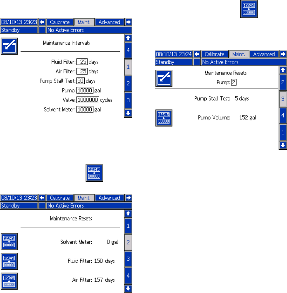
Setup Mode Screens
Maintenance Screens
Maintenance Screen 1
Use this screen to set maintenance intervals. Set
to 0 to disable the alarm.
NOTE: The Pump Stall Test cannot be disabled. You
must enter a value other than 0.
Figure 48 Maintenance Screen 1, Interval Settings
Maintenance Screen 2
Maintenance screen 2 shows the current interval
status of the solvent meter, fluid filter, and air filter.
Press and hold the Reset button for 1-2
seconds to clear the alarm and reset the counter.
Figure 49 Maintenance Screen 2, Current Status
Maintenance Screen 3
Maintenance screen 3 shows the current interval
status of the pump maintenance tests.
Press and hold the Reset button for 1-2
seconds to clear the alarm and reset the counter.
NOTE: ThePumpStallTestcanonlyberesetby
successfully completing the test.
Figure 50 Maintenance Screen 3, Current Pump
Status
80 332564B
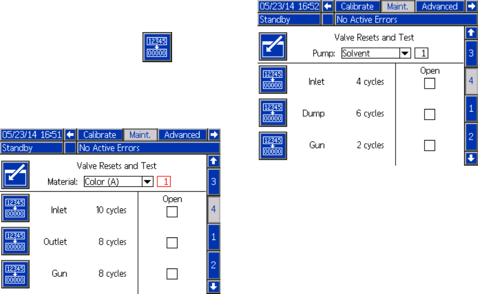
Setup Mode Screens
Maintenance Screen 4
Maintenance screen 4 displays cycle counts for a
selected color, catalyst, or solvent valve.
Press and hold the Reset button for 1-2
seconds to reset the counter.
If the system is in Standby, valves can be opened
or closed by selecting or deselecting the box for the
corresponding valve.
Figure 51 Maintenance Screen 4, Color Valve Resets
Figure 52 Maintenance Screen 4, Solvent Valve
Resets
NOTE: In Fig. 48, the number to the right of “Solvent”
is the pump number, not the material number.
332564B 81
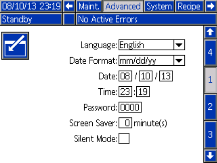
Setup Mode Screens
Advanced Screen 1
Advanced screen 1 sets the following display
parameters.
Figure 53 Advanced Screen 1
Language
Defines the language of the screen text. Select:
• English (default)
• Spanish
•French
•German
• Japanese
• Chinese
• Korean
•Dutch
• Italian
•Port
uguese
•Swedish
•Russian
Date Format
Select mm/dd/yy, dd/mm/yy, or yy/mm/dd.
Date
Enter the date, using the format selected. Use two
digits for the month, day, and year.
Time
Enter current time in hours (24 hour clock) and
minutes. Seconds are not adjustable.
Password
The password is only used to enter Setup mode.
The default is 0000, which means no password is
required to enter Setup. If a password is desired,
enter a number from 0001 to 9999.
NOTE: Be sure to write down the password and keep
it in a secure location.
Screen Saver
Select the desired screen timeout in minutes (00-99).
5isth
e default. Select zero (0) to disable the screen
saver.
SilentMode
Select Silent Mode to disable the alarm buzzer and
audible feedback.
82 332564B
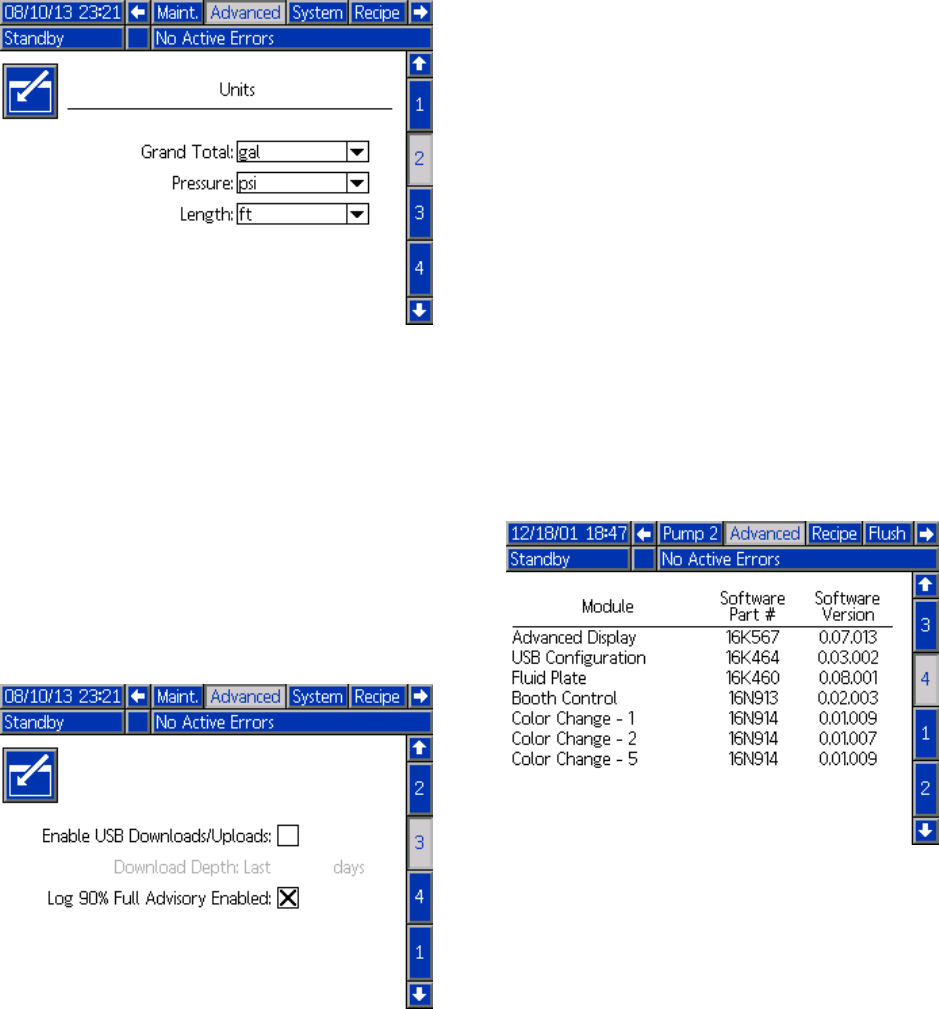
Setup Mode Screens
Advanced Screen 2
Advanced screen 2 sets display units (US or metric).
Figure 54 Advanced Screen 2
Display Units
Select the desired display units:
• Grand Total Volume (US gallon or liter)
• Pressure (psi, bar, or MPa)
• Length (ft or m)
Advanced Screen 3
Advanced screen 3 enables USB downloads and
uploads.
Figure 55 Advanced Screen 3
Enable USB Downloads/Uploads
Select this box to enable USB downloads and
uploads. Enabling USB activates the Download
Depth field.
Download Depth
Enter the number of days for which you want to
retrieve data. For example, to retrieve data for the
previous week, enter 7.
Log 90% Full Advisory Enabled
This selection is enabled by default. When enabled,
the system will issue an advisory if the memory log
has reached 90% of capacity. Perform a download to
avoid loss of data.
Advanced Screen 4
Advanced screen 4 displays the software part
numbers and versions for the system components.
This is not an editable screen.
Figure 56 Advanced Screen 4
332564B 83

Calibration Checks
Calibration Checks
Pump Pressure Check
NOTE: Enter the transducer calibration data before
doing the pressure check.
Perform the pressure check:
• The first time the system is operated.
• Whenever new materials are used in the system,
especially if the materials have viscosities that
differ significantly.
• At least once per month as part of regular
maintenance.
• Whenever a pump is serviced or replaced.
During each pressure test, the dose valve will close
during an up stroke and a down stroke (in either
order). This test is to verify that the valves are
seating properly and not leaking. If leaking occurs,
the system will alarm after the test for that particular
pump direction.
NOTE: Do not trigger the spray device during the
pressure check.
1. The pump and lines must be primed with color or
catalyst before doing the Pressure Check. See
PrimeandFilltheSystem,page20.
2. If the display is on a Run Mode screen, press
to access setup screens.
3. Scroll to Calibrate to display
Calibrate Screen 1, page 77.
4. Press the Pressure Check button for the
desired pump. The pump will build pressure in
the line to a minimum of the Stall Test Pressure.
The pump will then move to the center stroke
position and stall test the upstroke, followed by
the downstroke.
5. The pressure and flow that the unit measured
are displayed on the screen. Compare
with the maximum leak rate entered on
System Screen 2, page 68. If the values are
substantially different, repeat the test.
NOTE: The stall test pressure set point is a
minimum. The system may stall at a higher
pressure depending on hose lengths and fluid
composition.
84 332564B
Calibration Checks
Pump Volume Check
1. The pump and lines must be primed with color or
catalyst before doing the Volume Check. See
Prime and Fill the System, page 20.
2. If the display is on a Run Mode screen, press
to access setup screens.
3. Scroll to Calibrate in the menu bar.
4. Scroll to Calibrate Screen 2, page 78.
5. Press the soft key for the pump you want
to check.
NOTE: For maximum accuracy, use a gravimetric
(mass) method to determine the actual volumes
dispensed. Verify that the fluid line is filled and
at the proper pressure before checking. Air in
thelineorpressurethatistoohighmaycause
incorrect values.
6. Press the Reset key . The volume counter
will reset to 0.
7. Trigger the gun into a graduated cylinder.
Dispense a minimum of 500cc of material.
8. The volume that the unit measured displays on
the screen.
9. Compare the amount on the screen to the
amount in the graduated cylinder.
NOTE: If the value is substantially different,
repeat the test. If the dispensed volume and
measured volume still do not match, check that
theAandBpumppositionsarenotreversed.
NOTE: Stop triggering the gun and press
to cancel the test.
332564B 85
Calibration Checks
Solvent Meter Calibration
1. The meter and lines must be primed with
solvent before doing the calibration. See
PrimeandFilltheSystem,page20.
2. If the display is on a Run Mode screen, press
to access setup screens.
3. Scroll to Calibrate in the menu bar.
4. Scroll to Calibrate Screen 3, page 79.
5. Press the soft key to initiate the calibration.
NOTE: For maximum accuracy, use a gravimetric
(mass) method to determine the actual volumes
dispensed.
NOTE: Verify that the fluid line is filled and at the
proper pressure before calibrating. Air in the line
or pressure that is too high may cause incorrect
calibration values.
6. Trigger the gun into a graduated cylinder.
Dispense a minimum of 500cc of material.
7. The volume that the unit measured displays on
the screen.
8. Compare the amount on the screen to the
amount in the graduated cylinder.
NOTE: If the value is substantially different,
repeat the calibration process.
9. Enter the amount of solvent dispensed in the
Measured Volume field on the screen.
10. After the measured volume is entered, the
controller calculates the new solvent meter
K-factor and displays it on the screen. The
standard meter K-factor is 0.021 cc/pulse.
11. Press to accept the calibration. Press
to cancel the calibration and retain the previous
K-factor.
86 332564B

Color Change
Color Change
Color Change Module Kits are available as an
accessory. See manual 333282 for complete
information.
Single Color Systems
1. Follow the procedure under
Flush the System, page 23.
2. Load the new color. See
Prime and Fill the System, page 20.
3. Command the system to Mix to start spraying.
Multiple Color Systems
1. Command the system to Standby.
2. Enable manual override on
System Screen 5, page 71.
3. Select the new recipe on the
Spray Screen, page 62. This will change
colors in the pump and initiate a gun purge.
4. The system will purge material B then material
A out of the gun. Each material will purge for
the amount of time designated by the Flush
Sequence selected for each material on the
Recipe Screen, page 72.
5. Wait for the color change to complete. The
system automatically goes from Color Change to
Mix Fill and the remote mix manifold automatically
selects the correct color.
6. Trigger the gun to complete the Mix Fill.
NOTE: There is a 10 second delay without flow
before the system will fault.
7. Wait for the system to complete the Mix Fill
operation. Command the system to Mix and
begin spraying..
332564B 87

System Errors
System Errors
System errors alert you of a problem and help
prevent off-ratio spraying. There are three types:
Advisory, Deviation, and Alarm.
An Advisory records an event in the system, and will
clear itself after 60 seconds.
ADeviation records an error in the system but does
not shut down the equipment. The deviation must be
acknowledged by the user.
If an Alarm occurs, operation stops.
If any of the three types occur:
• Alarm buzzer sounds (unless in silent mode).
• Alarm popup screen shows the active alarm code
(see Error Codes, page 89).
• Status bar on the Advanced Display Module shows
theactivealarmcode.
• Alarm is saved in the date/time stamped log.
To Clear Error and Restart
NOTE: When a deviation or alarm occurs, be
sure to determine the error code before resetting
it. If you forget which code occurred, go to the
Errors Screen, page 65, to view the last 200 errors,
with date and time stamps.
If an alarm has occurred, correct the cause before
resuming operation.
To acknowledge a deviation or clear an alarm, press
on the Advanced Display Module. Users also
may acknowledge and clear errors via a network
device. INPUT REGISTER 08: Clear Active Alarm in
ProMix PD2K Network Inputs, page 36.
Gun Trigger Input Function
The Gun Trigger Input signals the controller when
the gun is triggered. The gun icon on the Advanced
Display Module shows spray when the Gun Trigger
Input is activated.
If a pump fails, pure resin or catalyst could spray
indefinitely if the unit does not detect the condition
and intervene, which is why the Gun Trigger Input
is so important.
If the unit detects through the Gun Trigger Input
signal that the gun is triggered, yet one or both of the
pumps are not running, a Flow Not Detected Alarm
(F8D1) occurs after 10 seconds (default) and the
system goes into Standby.
88 332564B

System Errors
Error Codes
NOTE: When an error occurs be sure to determine the code before resetting it. If you forget which code
occurred, use the Errors Screen, page 65 to view the last 200 errors, with date, time, and description.
Purge Errors
Code Type Description Problem Cause Solution
Air flow switch is stuck
in flow position.
Clean or replace switch.
Leak downstream in air
line or fitting.
Check for leaks and
tighten fittings.
F7P1 Alarm Air Flow
Switch On
The air flow switch is
indicating unexpected
atomizing air flow.
Air supply pressure
fluctuation.
Eliminate pressure
fluctuations.
Solvent flow switch not
working.
Replace switch.
Solvent flow is too low
to actuate the solvent
switch.
Increase solvent
pressure to drive a
high purge flow rate
Gun is not triggered. Operator must continue
flushing for configured
time, until the booth
control indicates purge
is completed.
SPD1 Alarm Gun Purge
Incomplete
Thesystemtimedout
without reaching the
user-specified volume
of solvent for a purge.
Mix manifold was not
set to flush position,
blocking solvent flow to
the spray gun.
Setmanifoldtoflush
position.
Mix Errors
Code Type Description Problem Cause Solution
Solvent flow switch is
stuck in flow position.
Clean or replace switch.F7S1 Alarm Flow
Detected
Solvent
Gun
The solvent flow
switch is indicating
unexpected solvent
flow. There is a leak through
the solvent cutoff valve.
Check for leaks and
repair valve.
Purge process was not
completed.
Make sure purge
process is completed.
QPD1 Alarm,
then
Devia-
tion
Potlife
Expired
Potlife time has expired
before the system has
moved the required
amount of material
(potlife volume) through
the mixed material line.
Solvent supply shut off
or empty.
Verify solvent supply
is available and on,
supply valves are open.
Mix manifold not set to
spray position.
Set manifold to spray.
Spraygunwasnot
triggered.
Allow flow through gun
during fill process until
the fill complete LED
stops flashing.
SND1 Alarm Mix Fill
Incomplete
The system timed out
before the mix fill cycle
loaded the gun with
mixed material.
Restrictions in mixer,
manifold, or spray gun.
Fix restrictions.
332564B 89

System Errors
Pumping Errors
NOTE: In some error codes listed below, a # symbol is shown as the last digit. This symbol represents the
applicable component number, which can vary. The unit’s display will show the applicable number as the
last digit in the code. For example, the F1S# code listed in this table will be displayed as F1S1 if the affected
component is pump 1, F1S2 for pump 2, and so on.
Code Type Description Problem Cause Solution
System has a leak
or open valve that is
allowing unrestricted
flow.
Inspect system for
leaks.
Pump is cavitating,
cycling without
restriction.
Verify that the pump
is being supplied with
material.
Viscosity of material is
too thin for nozzle size.
Reduce nozzlesizeto
create more restriction.
Reduce paint pressure
to lower the flow rate.
DA0# Alarm Exceeded
Maximum
Flow Pump
#
Pump was driven to
its maximum allowed
speed.
System pressure or
Flow Setpoint is too
high (causing the pump
to work too hard).
Reduce the pressure or
the Flow Setpoint.
No material in the pump
or line.
Make sure the pump
and down stream color
line areloadedwith
material.
DE0# Alarm Leak
Detected
Pump #
This is a manual stall
test failure when the
pump cannot build
pressure to the target
“Stall Test Pressure.”
Will fault after 30
seconds.
Leak in the system. Determine if leak is
external or internal
by visually inspecting
the system for fluid
leakage. Fix all loose
or worn hoses, fittings,
and seals. Inspect
all valve seats and
needles for wear, and
replace worn piston or
throat seals.
DF0# Alarm No Stall Up
Pump #
Pump failed the stall
test; did not stall on the
upstroke.
Valve failure, seal
failure, worn rod or
cylinder.
Replace inlet and outlet
valve and seal for
up stroke. Replace
piston and throat
seals. Replace rod and
cylinder as necessary.
DG0# Alarm No Stall
Down Pump
#
Pump failed the stall
test; did not stall on the
downstroke.
Valve failure, seal
failure, worn rod or
cylinder.
Replace inlet and outlet
valve and seal for
down stroke. Replace
piston and throat
seals. Replace rod and
cylinder as necessary.
90 332564B

System Errors
Code Type Description Problem Cause Solution
DH0# Alarm No Stall
Pump #
Pump failed thestall
test; did not stall on
either the upstroke or
the downstroke.
Valve failure, seal
failure, worn rod or
cylinder.
Replace inlet and outlet
valve and seal for up
and down strokes.
Replacepistonand
throat seals. Replace
rod and cylinder as
necessary.
DK0# Alarm Position
Pump #
Pump was detected to
be out of position.
Re-enable pump power
to reset pump. Make
sure inlet supply
pressure is not too
high.
EBH# Rec-
ord
Home
Complete
Pump #
Record of pump homing
is complete.
An indication on the
display that the pump
completed the home
function
No action required.
Pump dose valves did
not actuate.
Verify airpressure
to solenoid valves.
Verify the valves are
actuating.
Motor could not drive
pumps and linear
actuator.
Verify motor is driving
the pump.
EF0# Alarm Timeout
Startup
Pump #
Pump tried but was not
abletomovetothe
home position within
a specified amount of
time.
Pump stroke length
is shortened by
mechanical system
tolerance.
Verify correct assembly
of linear actuator and
pump piston rods. See
pump manual.
Pump dose valves did
not actuate.
Visually inspect valves
to ensure they are
operating properly;
verify they have air
pressure above 85 psi
(0.6 MPa, 6.0 bar).
EF1# Alarm Timeout
Shutdown
Pump #
Pump tried but was not
abletomovetothe
park position within a
specified amount of
time.
Pump is filled with thick
paint and could not
drive piston to end of
stroke. Motor or drive
is worn or damaged.
Observe motor and
drive assembly to
verify that the motor is
generating force.
332564B 91

System Errors
Code Type Description Problem Cause Solution
There is a restriction on
the outlet side of the
pump or color stack.
Make sure there are no
restrictions in the color
stack and that the dump
valve is actuating.
Thick viscosity paint
requires more pressure
to pump.
Increase non-mix
pressure if necessary
to create flow during
the fill function.
F1F# Alarm Flow Low
Fill Pump #
There has been no flow
or low flow during a
pump fill operation.
The pumps do not
have to move for the
system to build enough
pressure to meet the
setpoint.
Increase non-mix
pressure if necessary
to create flow during
the fill function.
F1S# Alarm Flow Low
Purge Pump
#
There has beennoflow
or low flow during a
pump purge operation.
Restriction in the outlet
side of the pump or
color stack resulting in
the solvent flow being
too low.
Make sure there are
no restrictions in the
system. Increase
non-mix pressure if
necessary to create
flow during the purge
function.
F7D# Alarm Flow
Detected
Pump #
Thepumpflow
exceeded 20 cc/min
flowcomingintoIdle
mode.
There is a leak in the
system or the gun was
open when the system
went into Idle mode.
Verify there are no
leaks in the system.
Make sure the air flow
switch is actuating
properly. Do not
trigger the gun without
atomizing air.
F8D1 Alarm Flow Not
Detected
No flow while mixing. Restriction in the outlet
side of the pump or
color stack.
Make sure there are
no restrictions in the
system.
F9D# Alarm Flow
Unstable
Pump #
Thepumpflowrate
did not stabilize while
entering Idle mode.
Potential leak in the
system.
Check the system for
leaks and run manual
stall test.
SAD1Alarm Atomizing
Solvent
Air flow switch is
active while solvent,
diluted material, or an
unknown material is in
the gun.
Atomizing air supply
was not shut off before
purging or filling spray
gun.
Make sure atomizing
air is shut off before
purging or filling the
spray gun. Use an
AA cutoff valve on the
atomizing air supply.
92 332564B

System Errors
Pressure Errors
NOTE: In some error codes listed below, a # symbol is shown as the last digit. This symbol represents the
applicable component number, which can vary. The unit’s display will show the applicable number as the
last digit in the code. For example, the P6F# code listed in this table will be displayed as P6F1 if the affected
component is pump 1, P6F2 for pump 2, and so on.
Code Type Description Problem Cause Solution
F6F# Alarm Press.
Sens.
Removed
Inlet #
No inlet pressure
transducer is detected
when the system is
expecting one.
Disconnected
transducer.
Verify transducer is
connected properly.
Replace if reconnecting
does not eliminate the
alarm.
P1F# Alarm Pressure
Low Inlet
Pump #
The inlet pressure on
pump # is less than
the user-entered alarm
limit.
Increase inlet pressure.
P2F# Devi-
ation
Pressure
Low Inlet
Pump #
The inlet pressure on
pump # is less than the
user-entered deviation
limit.
Increase inlet pressure.
P3D# Devi-
ation
Pressure
High Outlet
Pump #
The outlet pressure
on pump # is greater
than the user entered
deviation limit.
Relieve system
pressure.
P3F# Devi-
ation
Pressure
High Inlet
Pump #
The inlet pressure
on pump # is greater
than the user-entered
deviation limit.
Decrease inlet
pressure.
P4D# Alarm Pressure
High Outlet
Pump #
Theoutletpressureon
pump # is greater than
the user entered alarm
limit.
Relieve system
pressure.
P4F# AlarmPressure
High Inlet
Pump #
The inlet pressure on
pump # is greater than
the user-entered alarm
limit.
Decrease inlet
pressure.
P6D# Alarm Press.
Sens.
Removed
Outlet #
No outlet pressure
transducer is detected
when the system is
expecting one.
Disconnected
transducer.
Verify transducer is
connected properly.
Replace if reconnecting
does not eliminate the
alarm.
P9D# Alarm Press.
Sens.
Failed
Outlet #
Outlet pressure
transducer has failed.
Outlet pressure
transducer has failed or
the pressure is above
the readable range.
Relieve system
pressure. Verify
connections, or replace
if reconnecting does
not eliminate the alarm.
332564B 93

System Errors
Code Type Description Problem Cause Solution
P9F# Alarm Press.
Sens.
Failed Inlet
#
Inlet pressure
transducer has failed.
Inlet pressure
transducer has failed or
thepressureisabove
the readable range.
Relieve system
pressure. Verify
connections, or replace
if reconnecting does
not eliminate the alarm.
There is a leakonthe
B side.
Check the system
for internal and
external leaks on all
catalyst manifolds and
plumbing.
QADX Alarm Differential
Pressure A
Over B
Low differential
pressure. This alarm is
active only during Mix
mode.
The B side pump is
cavitating.
Check paint supply on
the B side, increase
paint supply pressure.
There is a leak on the
A side.
Check the system
for internal and
external leaks on all
color manifolds and
plumbing.
QBDX Alarm Differential
Pressure B
Over A
High differential
pressure. This alarm is
active only during Mix
mode.
The A sidepumpis
cavitating.
Check paint supply on
the A side, increase
paint supply pressure.
94 332564B

System Errors
System Errors
Code Type Description Problem Cause Solution
EB00 Rec-
ord
Stop Button
Pressed
Recordofastopbutton
press.
Indicates system stop
key on ADM was
pressed.
n/a
EC00 Rec-
ord
Setup
Value(s)
Changed
Record of changing
setup variables.
Indicates date and time
when setup values
were changed.
n/a
EL00 Rec-
ord
System
Power On
Record of power cycle
(ON).
Indicates date and
time when system was
started.
n/a
EM00 Rec-
ord
System
Power Off
Record of power cycle
(OFF).
Indicates date and
time when system was
turned off.
n/a
EMIX Advi-
sory
Pump Off The pumps are not
powered and are
unable to move.
Pump powerwas
turned offoranerror
occurred.
Start pumps by
pressing pump start
key on Advanced
Display module.
ES00 Advi-
sory
Factory
Defaults
Record of defaults
being loaded.
n/a
Communication Errors
NOTE: In some error codes listed below, a # symbol is shown as the last digit. This symbol represents the
applicable component number, which can vary. The unit’s display will show the applicable number as the last
digit in the code. For example, the CAC# code listed in this table will be displayed as CAC1 if the affected
component is color change board 1, CAC2 for board 2, and so on.
Code Type Description Problem Cause Solution
CA0X Alarm Comm. Error
ADM
System does not
detect the Advanced
Display Module
(ADM).
This communication
error indicates that
the Network has lost
communication with
the Advanced Display
Module.
Check CAN cable
connecting ADM to
the EFCM.
CAC# Alarm Comm. Error
Color Change
#
System does not
detect the Color
Change Module #.
This communication
error indicates that
the network has lost
communication with
the Color Change
Module #.
Check CAN cable
connections to
the Color Change
Module # and any
interconnected
modules.
CADX Alarm Comm. Error
Fluid Module
System does not
see the Enhanced
Fluid Control Module
(EFCM).
This communication
error indicates that
the Network has lost
communication with
the EFCM.
Check CAN cables
connecting ADM to
the EFCM. Replace
Cable or EFCM as
necessary.
332564B 95

System Errors
Code Type Description Problem Cause Solution
CAGX Alarm Comm. Error
Gateway
System does not
detect a CGM that
was registeredas
being connected at
power up.
CDC# Alarm Duplicate
Color Change
#
System detects two or
more identical Color
Change Modules.
More than one Color
Change Module with
thesameaddress
is connected in the
system .
Check the system
and remove the extra
color change module.
CDDX Alarm Duplicate
Fluid Module
System sees two
or more identical
Enhanced Fluid
Control Modules
EFCM).
More than one EFCM
is connected in the
system.
Check the system
and remove the extra
EFCM.
96 332564B

System Errors
USB Errors
Code Type Description Problem Cause Solution
EAUX Advi-
sory
USB Busy USB drive is inserted,
download is in
progress.
Indicates USB port
is uploading or
downloading data.
Wait for USB Idle.
EBUX Record USB Drive
Removed
USB drive was
removed while
downloading or
uploading.
Downloading/upload-
ingdataonUS
Bwas
interruptedbythe
USB device being
removed.
Replace the USB
device and begin
process again.
EQU0 Advi-
sory
USB Idle USB download
completed, drive
may be removed.
Data transfer is
completedtothe
USB device.
Remove USB device
from ADM.
EQU1 Record USB Sys.
Settings
Downloaded
Settings were
downloaded to USB
drive.
User installed USB
device in ADM USB
port.
n/a
EQU2 Record USB Sys.
Settings
Uploaded
Settingswere
uploadedfromUSB
drive.
User installed USB
device in ADM USB
port.
n/a
EQU3 Record USB Custom
Lang.
Downloaded
Custom language
was downloaded to
USB drive.
User installed USB
device in ADM USB
port.
n/a
EQU4 RecordUSB Custom
Lang.
Uploaded
Custom language
was uploaded from
USB drive.
User installed USB
device in ADM USB
port.
n/a
EQU5 Record USB Logs
Downloaded
Data logs were
downloaded to USB
drive.
User installed USB
device in ADM USB
port.
n/a
EVUX Advi-
sory
USB Disabled USB drive has
been inserted,
downloading is
disabled.
Configuration of
system is blocking
data transfer.
Change configuration
to enable USB
download function.
MMUX Advi-
sory
Maint. USB
Logs Full
USB memory is more
than 90% full.
Configuration
parameter on
system is enabled
to generate this
advisory.
Complete download
to ensure no data is
lost.
WSUX Advi-
sory
USB Config.
Err.
USB configuration
file does not match
expected; checked
on startup.
Asoftware update
was not completed
successfully.
Reinstall software.
332564B 97

System Errors
Code Type Description Problem Cause Solution
WXUD Advi-
sory
USB
Download Err.
An error occurred
while downloading to
the USB drive.
User installed
incompatible USB
device in ADM USB
port.
Repeat process with
compatible USB
device.
WXUU Advi-
sory
USB Upload
Err.
An error occurred
while uploading from
the USB drive.
User installed
incompatibleUSB
device in ADM USB
port.
Repeat process with
compatible USB
device.
98 332564B

System Errors
Miscellaneous Errors
NOTE: In some error codes listed below, a # symbol is shown as the last digit. This symbol represents the
applicable component number, which can vary. The unit’s display will show the applicable number as the last
digit in the code. For example, the B9D# code listed in this table will be displayed as B9D1 if the affected
component is pump 1, B9D2 for pump 2, and so on.
Code Type Description Problem Cause Solution
B9A0 Advi-
sory
Volume
Rollover A
Current
Batch counterfor
material A rolled over.
The totalizer has
reached maximum
capable value and
started over at zero.
n/a
B9AX Advi-
sory
Volume
Rollover A
Lifetime
Grand total counter
for material A rolled
over.
The totalizer has
reached maximum
capable value and
started over at zero.
n/a
B9B0 Advi-
sory
Volume
Rollover B
Current
Batch counter for
material B rolled over.
The totalizer has
reached maximum
capable value and
started over at zero.
n/a
B9BX Advi-
sory
Volume
Rollover B
Lifetime
Grand total counter
for material B rolled
over.
The totalizer has
reached maximum
capable value and
started over at zero.
n/a
B9D# Advi-
sory
Volume
Rollover
Pump #
Grand total counter
forpump#rolled
over.
The totalizer has
reached maximum
capable value and
startedoveratzero.
n/a
B9S0 Advi-
sory
Volume
Rollover
Solvent
Current
Batch counter for
solvent rolled over.
The totalizer has
reached maximum
capable value and
started over at zero.
n/a
B9SX Advi-
sory
Volume
Rollover
Solvent
Lifetime
Grand total counter
for solvent rolled
over.
The totalizer has
reached maximum
capable value and
started over at zero.
n/a
WX00 AlarmSoftware
Errors
An unexpected
software error has
occurred.
Call Graco technical
support.
332564B 99

System Errors
Calibration Errors
NOTE: In some error codes listed below, a # symbol is shown as the last digit. This symbol represents the
applicable component number, which can vary. The unit’s display will show the applicable number as the last
digit in the code. For example, the ENT# code listed in this table will be displayed as ENT1 if the affected
component is pump 1, ENT2 for pump 2, and so on.
Code Type Name Description
END# Record Calibration Pump # A calibration test was run on the pump.
ENS0 Record Calibration Solvent Meter A calibration test was run on the solvent
meter.
ENT# Record CalibrationStallTestPump
#
A stall test was completed successfully
on pump #.
100 332564B
System Errors
Maintenance Errors
NOTE: In some error codes listed below, a # symbol is shown as the last digit. This symbol represents the
applicable component number, which can vary. For example, the MAD# code listed in this table will be
displayed as MAD1 if the affected component is pump 1, MAD2 for pump 2, and so on.
Because some components are assigned a 2–digit number, the last digit of the code is displayed as an
alphanumeric character. The second table below correlates the alphanumeric digit to its component number.
For example, code MEDZ represents outlet valve 30.
Code Type Name Description
MAD# Advisory Maint. Outlet Pump # Maintenance is due on pump.
MAT# Advisory Maint. StallTest
Pump #
Maintenance stall test is due on pump.
MEB# Advisory Maint. Valve Catalyst
(B) #
Maintenance is due on catalyst valve.
MED# Advisory Maint. Valve Outlet # Maintenance is due on outlet valve.
MEF# Advisory Maint. Valve Inlet # Maintenance is due on inlet valve.
MEG# Advisory Maint. Valve Gun # Maintenance is due on gun valve.
MES# Advisory Maint. Valve Solvent
#
Maintenance is due on solvent valve.
MFF# Advisory Maint. Meter Flow # Maintenance is due on flow meter.
MFS0 Advisory Maint. Meter Solvent Maintenance stall test is due on solvent meter.
MGH0 Advisory Maint. Filter Fluid Maintenance is due on fluid filter.
MGP0Advisory Maint. Filter Air Maintenance is due on air filter.
Alphanumeric Last Digits
Alphanumeric Digit Component Number
11
22
33
44
55
66
77
88
99
A10
B11
C12
D13
E14
F15
Alphanumeric Digit Component Number
G16
H17
J18
K1
9
L20
M21
N22
P23
R24
T25
U26
V27
W28
Y29
Z30
332564B 101
Maintenance
Maintenance
Preventive Maintenance Schedule
The operating conditions of your particular system
determine how often maintenance is required.
Establish a preventive maintenance schedule by
recording when and what kind of maintenance is
needed, and then determine a regular schedule for
checking your system.
Flushing
• Flush before changing fluids, before fluid can dry
in the equipment, at the end of the day, before
storing, and before repairing equipment.
• Flush at the lowest pressure possible. Check
connectors for leaks and tighten as necessary.
• Flush with a fluid that is compatible with the fluid
being dispensed and the equipment wetted parts.
Cleaning theADM
Use any alcohol-based household cleaner, such as
glass cleaner, to clean the ADM.
102 332564B
Technical Data
Technical Data
Positive Displacement
Proportioner
U.S. Metric
Maximum fluid working
pressure:
AC1000 Air Spray
Systems
300 psi 2.1 MPa, 21 bar
AC2000 Air-Assisted
Spray Systems
1500 psi 10.5 MPa, 105bar
Maximum working air
pressure:
100 psi 0.7 MPa, 7.0bar
Air supply: 85–100 psi 0.6–0.7 MPa, 6.0–7.0 bar)
Air filter inlet size: 3/8 npt(f)
Air filtration for air logic
(user-supplied):
5micron(minimum) filtration required; clean and dry air
Air filtration for atomizing
air (user-supplied):
30 micron (minimum) filtration required; clean and dry air
Mixing ratio range: 0.1:1 — 50:1, ±1%
Fluids handled: one or two component:
• solvent and waterborne paints
• polyurethanes
• epoxies
• acid catalyzed varnishes
• moisture sensitive isocyanates
Viscosity range of fluid: 20–5000 centipoise
Fluid filtration
(user-supplied):
100meshminimum
Maximum fluid flow: 800 cc/minute (depending on material viscosity)
Fluid outlet size: 1/4 npt(m)
External power supply
requirements:
90 - 250 Vac, 50/60 Hz, 7 amps maximum draw
15 amp maximum circuit breaker required
8 to 14 AWG power supply wire gauge
Operating temperature
range:
36 to 122°F 2 to 50°C
Storage temperature
range:
—4 to 158°F —20 to 70°C
Weight (approximate): 195 lb 88 kg
Sound data: Less than 75 dB(A)
Wetted parts: 17–4PH, 303, 304 SST, Tungsten carbide (with nickel binder),
perfluoroelastomer; PTFE, PPS, UHMWPE
332564B 103

Graco Standard Warranty
Graco warrants all equipment referenced in this document which is manufactured by Graco and bearing its
name to be free from defects in material and workmanship on the date of sale to the original purchaser for use.
With the exception of any special, extended, or limited warranty published by Graco, Graco will, for a period of
twelve months from the date of sale, repair or replace any part of the equipment determined by Graco to be
defective. This warranty applies only when the equipment is installed, operated and maintained in accordance
with Graco’s written recommendations.
This warranty does not cover, and Graco shall not be liable for general wear and tear, or any malfunction,
damage or wear caused by faulty installation, misapplication, abrasion, corrosion, inadequate or improper
maintenance, negligence, accident, tampering, or substitution of non-Graco component parts. Nor shall Graco
be liable for malfunction, damage or wear caused by the incompatibility of Graco equipment with structures,
accessories, equipment or materials not supplied by Graco, or the improper design, manufacture, installation,
operation or maintenance of structures, accessories, equipment or materials not supplied by Graco.
This warranty is conditioned upon the prepaid return of the equipment claimed to be defective to an authorized
Graco distributor for verification of the claimed defect. If the claimed defect is verified, Graco will repair or replace
free of charge any defective parts. The equipment will be returned to the original purchaser transportation
prepaid. If inspection of the equipment does not disclose any defect in material or workmanship, repairs will be
made at a reasonable charge, which charges may include the costs of parts, labor, and transportation.
THIS WARRANTY IS EXCLUSIVE, AND IS IN LIEU OF ANY OTHER WARRANTIES, EXPRESS OR IMPLIED,
INCLUDING BUT NOT LIMITED TO WARRANTY OF MERCHANTABILITY OR WARRANTY OF FITNESS
FOR A PARTICULAR PURPOSE.
Graco’s sole obligation and buyer’s sole remedy for any breach of warranty shall be as set forth above. The
buyer agrees that no other remedy (including, but not limited to, incidental or consequential damages for lost
profits, lost sales, injury to person or property, or any other incidental or consequential loss) shall be available.
Any action for breach of warranty must be brought within two (2) years of the date of sale.
GRACO MAKES NO WARRANTY, AND DISCLAIMS ALL IMPLIED WARRANTIES OF MERCHANTABILITY
AND FITNESS FOR A PARTICULAR PURPOSE, IN CONNECTION WITH ACCESSORIES, EQUIPMENT,
MATERIALS OR COMPONENTS SOLD BUT NOT MANUFACTURED BY GRACO. These items sold, but not
manufactured by Graco (such as electric motors, switches, hose, etc.), are subject to the warranty, if any, of
their manufacturer. Graco will provide purchaser with reasonable assistance in making any claim for breach of
these warranties.
In no event will Graco be liable for indirect, incidental, special or consequential damages resulting from Graco
supplying equipment hereunder, or the furnishing, performance, or use of any products or other goods sold
hereto, whether due to a breach of contract, breach of warranty, the negligence of Graco, or otherwise.
FOR GRACO CANADA CUSTOMERS
The Parties acknowledge that they have required that the present document, as well as all documents, notices
and legal proceedings entered into, given or instituted pursuant hereto or relating directly or indirectly hereto, be
drawn up in English. Les parties reconnaissent avoir convenu que la rédaction du présente document sera en
Anglais, ainsi que tous documents, avis et procédures judiciaires exécutés, donnés ou intentés, à la suite de ou
en rapport, directement ou indirectement, avec les procédures concernées.
Graco Information
For the latest information about Graco products, visit www.graco.com.
To place an order, contact your Graco Distributor or call to identify the nearest distributor.
Phone: 612-623-6921 or Toll Free: 1-800-328-0211 Fax: 612-378-3505
All written and visual data contained in this document reflects the latest product information available at the time of publication.
Graco reserves the right to make changes at any time without notice.
For patent information, see www.graco.com/patents.
Original Instructions. This manual contains English. MM 332564
Graco Headquarters: Minneapolis
International Offices: Belgium, China, Japan, Korea
GRACO INC. AND SUBSIDIARIES • P.O. BOX 1441 • MINNEAPOLIS MN 55440-1441 • USA
Copyright 2014, Graco Inc. All Graco manufacturing locations are registered to ISO 9001.
www.graco.com
Revision B, September 2014
