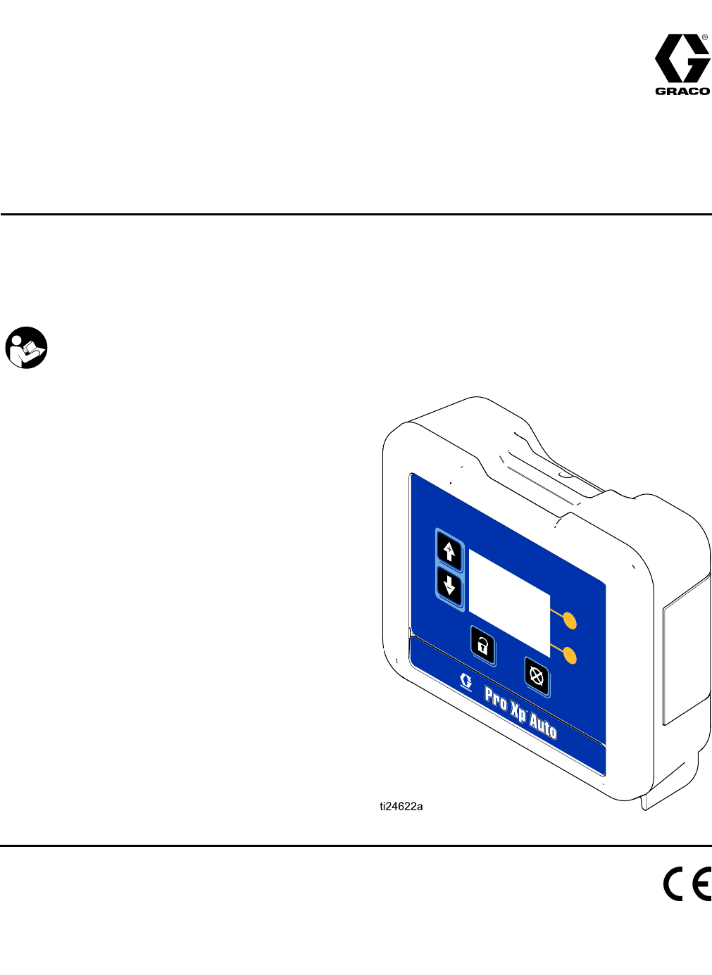
Graco 332989A Pro Xp Auto Control Module Users Manual 332989A, Module, Instructions, English
2015-04-02
: Graco Graco-332989A-Pro-Xp-Auto-Control-Module-Users-Manual-686504 graco-332989a-pro-xp-auto-control-module-users-manual-686504 graco pdf
Open the PDF directly: View PDF ![]() .
.
Page Count: 30
Instructions
Pro Pro
ProXp Xp
XpAuto Auto
AutoControl Control
ControlModule Module
Module332989A
EN
User User
UserInterface Interface
Interfacefor for
forPro Pro
ProXp Xp
XpAuto Auto
AutoElectrostatic Electrostatic
ElectrostaticSpray Spray
SprayGuns. Guns.
Guns.
For For
Forprofessional professional
professionaluse use
useonly. only.
only.
Important Important
ImportantSafety Safety
SafetyInstructions Instructions
Instructions
ReadallwarningsandinstructionsinthismanualandtheGraco
AutomaticElectrostaticGunmanuals.
Save Save
Savethese these
theseinstructions. instructions.
instructions.
PROVENQUALITY.LEADINGTECHNOLOGY.

Contents Contents
Contents
Warnings...........................................................3
Models...............................................................5
Overview............................................................5
RelatedManuals................................................5
Installation..........................................................6
CableConnections.......................................6
FiberOpticConnections...............................7
RemoteModeI/OConnection.......................8
PowerCordConnection...............................8
Grounding...................................................9
Operation...........................................................10
ModuleScreens...........................................10
Preset.........................................................10
ModuleKeys................................................10
Icons...........................................................12
ScreenNavigationandEditing......................13
ScreenMap.................................................14
RunScreens......................................................16
RunScreen1..............................................16
RunScreens2–5.........................................17
PasswordScreen.........................................17
SetupScreens....................................................18
SetupScreens1and2.................................18
SetupScreens3and4.................................19
SetupScreen5............................................20
SetupScreen6............................................20
EventCodeTroubleshooting...............................21
Troubleshooting..................................................23
DiagnosticInformation........................................23
Maintenance......................................................24
UpdateSoftware..........................................24
ReplaceBattery...........................................24
Repair................................................................25
FiberOpticCableRepair..............................25
FiberOpticBulkheadInstallation...................26
Parts..................................................................27
Accessories........................................................28
FiberOpticCablesforGun...........................28
FiberOpticCableRepairand
Accessories....................................28
ControlModuleI/OCableAccessory
Kits................................................28
MountingDimensions.........................................29
TechnicalData...................................................29
GracoStandardWarranty....................................30
2
332989A
Warnings
Warnings Warnings
Warnings
Thefollowingwarningsareforthesetup,use,grounding,maintenanceandrepairofthisequipment.The
exclamationpointsymbolalertsyoutoageneralwarningandthehazardsymbolreferstoprocedure-specic
risks.Whenthesesymbolsappearinthebodyofthismanualoronwarninglabels,referbacktothese
Warnings.Product-specichazardsymbolsandwarningsnotcoveredinthissectionmayappearthroughout
thebodyofthismanualwhereapplicable.
WARNING WARNING
WARNING
FIRE FIRE
FIREAND AND
ANDEXPLOSION EXPLOSION
EXPLOSIONHAZARD HAZARD
HAZARD
Flammablefumes,suchassolventandpaintfumes,inwork work
workarea area
areacanigniteorexplode.Tohelp
preventreandexplosion:
•Useequipmentonlyinwellventilatedarea.
•Eliminateallignitionsources;suchaspilotlights,cigarettes,portableelectriclamps,and
plasticdropcloths(potentialstaticarc).
•Keepworkareafreeofdebris,includingsolvent,ragsandgasoline.
•Donotplugorunplugpowercords,orturnpowerorlightswitchesonoroffwhenammable
fumesarepresent.
•Groundallequipmentintheworkarea.SeeGrounding Grounding
Groundinginstructions.
•Useonlygroundedhoses.
•Holdgunrmlytosideofgroundedpailwhentriggeringintopail.Donotusepaillinersunless
theyareantistaticorconductive.
•Stop Stop
Stopoperation operation
operationimmediately immediately
immediatelyifstaticsparkingoccursoryoufeelashock,Donotuse
equipmentuntilyouidentifyandcorrecttheproblem.
•Keepaworkingreextinguisherintheworkarea.
Staticchargemaybuilduponplasticpartsduringcleaningandcoulddischargeandignite
ammablevapors.Tohelppreventreandexplosion:
•Cleanplasticpartsonlyinwellventilatedarea.
•Donotcleanwithadrycloth.
ELECTRIC ELECTRIC
ELECTRICSHOCK SHOCK
SHOCKHAZARD HAZARD
HAZARD
Thisequipmentmustbegrounded.Impropergrounding,setup,orusageofthesystemcan
causeelectricshock.
•Turnoffanddisconnectpoweratmainswitchbeforedisconnectinganycablesandbefore
servicingorinstallingequipment.
•Connectonlytogroundedpowersource.
•Useonly3–wireextensioncords.
•Ensuregroundprongsareintactonpowerandextensioncords.
•Allelectricalwiringmustbedonebyaqualiedelectricianandcomplywithalllocalcodes
andregulations.
•Donotexposetorain.Storeindoors.
332989A 3

Warnings
WARNING WARNING
WARNING
PERSONAL PERSONAL
PERSONALPROTECTIVE PROTECTIVE
PROTECTIVEEQUIPMENT EQUIPMENT
EQUIPMENT
Wearappropriateprotectiveequipmentwhenintheworkareatohelppreventseriousinjury,
includingeyeinjury,hearingloss,inhalationoftoxicfumes,andburns.Thisequipmentincludes
butisnotlimitedto:
•Protectiveeyewear,andhearingprotection.
•Respirators,protectiveclothing,andglovesasrecommendedbytheuidandsolvent
manufacturer.
EQUIPMENT EQUIPMENT
EQUIPMENTMISUSE MISUSE
MISUSEHAZARD HAZARD
HAZARD
Misusecancausedeathorseriousinjury.
•Donotoperatetheunitwhenfatiguedorundertheinuenceofdrugsoralcohol.
•Donotexceedthemaximumworkingpressureortemperatureratingofthelowestrated
systemcomponent.SeeTechnical Technical
TechnicalData Data
Datainallequipmentmanuals.
•Useuidsandsolventsthatarecompatiblewithequipmentwettedparts.SeeTechnical Technical
TechnicalData Data
Data
inallequipmentmanuals.Readuidandsolventmanufacturer’swarnings.Forcomplete
informationaboutyourmaterial,requestMSDSfromdistributororretailer.
•Donotleavetheworkareawhileequipmentisenergizedorunderpressure.
•TurnoffallequipmentandfollowthePressure Pressure
PressureRelief Relief
ReliefProcedure Procedure
Procedurewhenequipmentisnotinuse.
•Checkequipmentdaily.Repairorreplacewornordamagedpartsimmediatelywithgenuine
manufacturer’sreplacementpartsonly.
•Donotalterormodifyequipment.Alterationsormodicationsmayvoidagencyapprovals
andcreatesafetyhazards.
•Makesureallequipmentisratedandapprovedfortheenvironmentinwhichyouareusingit.
•Useequipmentonlyforitsintendedpurpose.Callyourdistributorforinformation.
•Routehosesandcablesawayfromtrafcareas,sharpedges,movingparts,andhotsurfaces.
•Donotkinkoroverbendhosesorusehosestopullequipment.
•Keepchildrenandanimalsawayfromworkarea.
•Complywithallapplicablesafetyregulations.
4
332989A

Models
Models Models
Models
Model Model
ModelNumber Number
NumberSeries Series
SeriesDescription Description
Description
24W035AProXpAutoControlModulewithsoftware,mountingbracketandpowersupply
included.Fiberopticcablesmustbepurchasedseparately.
24X216AProXpAutoControlModule.ModuleOnly.
Overview Overview
Overview
TheProXpAutoControlModuleisforuseonlywithProXpAutoElectrostaticGunsmartmodels.Thecontrol
moduleprovidesauserinterfaceforuptotwoguns.RemoteI/OallowscommunicationwithaProgrammable
LogicController(PLC).Thedisplaycontrolmoduleperformsthefollowingfunctions:
•Displaythesprayingvoltageandcurrent.
•Changethegunvoltagesetting.
•Displaythegunturbinespeed.
•Storespraypresets.
•CommunicateequipmentfaultstoaPLC.
•Displayandsetmaintenancetotalizers.
•UseaPLCtoselectasprayprole.
Related Related
RelatedManuals Manuals
Manuals
Manual Manual
ManualDescription Description
Description
333010ProXpAutoAirSprayGun
333011ProXpAutoAASprayGun
333012ProXpAutoWaterborneAirSprayGun
333013ProXpAutoWaterborneAASprayGun
332989A 5
Installation
Installation Installation
Installation
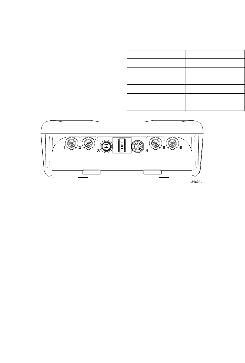
Cable Cable
CableConnections Connections
Connections
Ports1through4oftheProXpAutoControlModule
areusedinanautomaticelectrostaticguninstallation.
Port Port
PortDescription Description
Description
1FiberOptic1(Gun1)
2FiberOptic2(Gun1)
3PowerCord
4RemoteModeI/O
5FiberOptic1(Gun2)
6FiberOptic2(Gun2)
Figure1ProXpAutoControlModule
6 332989A
Installation
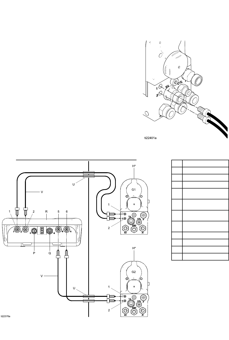
Fiber Fiber
FiberOptic Optic
OpticConnections Connections
Connections
(OperationalonSmartmodelsonly)
NOTE: NOTE:
NOTE:OnlyuseGracosuppliedberopticcable.See
FiberOpticCablesForGun,page28
Theberopticcableconnectstheberopticports
onthegunmanifoldtoPorts1and2ontheControl
Module.
For For
Fora a
a1 1
1Gun Gun
GunSystem System
System
1.ConnectPort1ofthegun1manifoldtoPort1of
theControlModule.
2.ConnectPort2ofthegun1manifoldtoPort2of
theControlModule.
For For
Fora a
a2 2
2Gun Gun
GunSystem System
System
1.ConnectPort1ofthegun2manifoldtoPort5of
theControlModule.
2.ConnectPort2ofthegun2manifoldtoPort6of
theControlModule.
Non-HazardousAreaHazardousArea
1Port1
2Port2
5Port5
6Port6
HProXpAutoSmart
Gun
P24VoltPowerSupply
Connection
QRemoteI/O
Connection
RProXpAutoControl
Module
UBulkhead(optional)
VFiberOpticCable
G1Gun1
G2Gun2
332989A
7
Installation
Remote Remote
RemoteMode Mode
ModeI/O I/O
I/OConnection Connection
Connection
TheuseoftheRemoteModeI/Ocapabilityis
optional.Connector4ontheControlModuleisthe
remotemodeI/Oport.
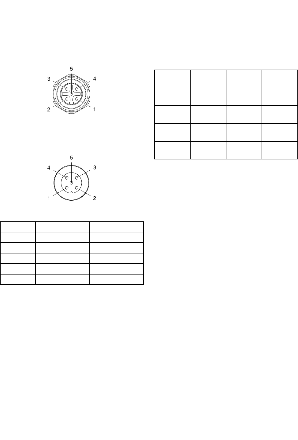
Figure2Connector4(I/O)Pinouts
RemotemodeI/Ocablesare
availableseparately.See
ControlModuleI/OCableAccessoryKits,page28
Figure3CablePinInformation
Pin Pin
PinNo. No.
No.Wire Wire
WireColor Color
ColorFunction Function
Function
1Brown+24VDC
2WhitePresetSelect1
3BlueLowkVAlarmOut
4BlackPresetSelect2
5GrayGND
Whenremotemodeisenabled,aPresetcanbe
selectedbyapplyingthefollowingsignalstoPreset
Select1(pin2)andPresetSelect2(pin4)of
connector4.
Preset Preset
Preset
Select Select
Select2 2
2
State State
State
Preset Preset
Preset
Select Select
Select1 1
1
State State
State
Encoding Encoding
EncodingSelected Selected
Selected
Preset Preset
Preset
GNDGND001
GND+24VDC
orFloating
012
+24VDC
orFloating
GND103
+24VDC
orFloating
+24VDC
orFloating
114
Duringnormaloperation,LowkVAlarmOut(pin3)
isat0V.Whenalowvoltagealarmoccurs,Low
kVAlarmOut(pin3)isat24VDC.Thisoccurs
regardlessofremotemodesetting.
NOTE: NOTE:
NOTE:LowkVAlarmOut(pin3)willread~18V
wheninactiveinanunloadedmeasurement.
Power Power
PowerCord Cord
CordConnection Connection
Connection
1.Connecttheadaptercord(supplied)toPort3on
thecontrolmodule.
2.Connectthe3–wirepowercord(supplied)tothe
adapter.
3.Plugthe3–wirepowercordintoagrounded
electricaloutlet.
8 332989A
Installation
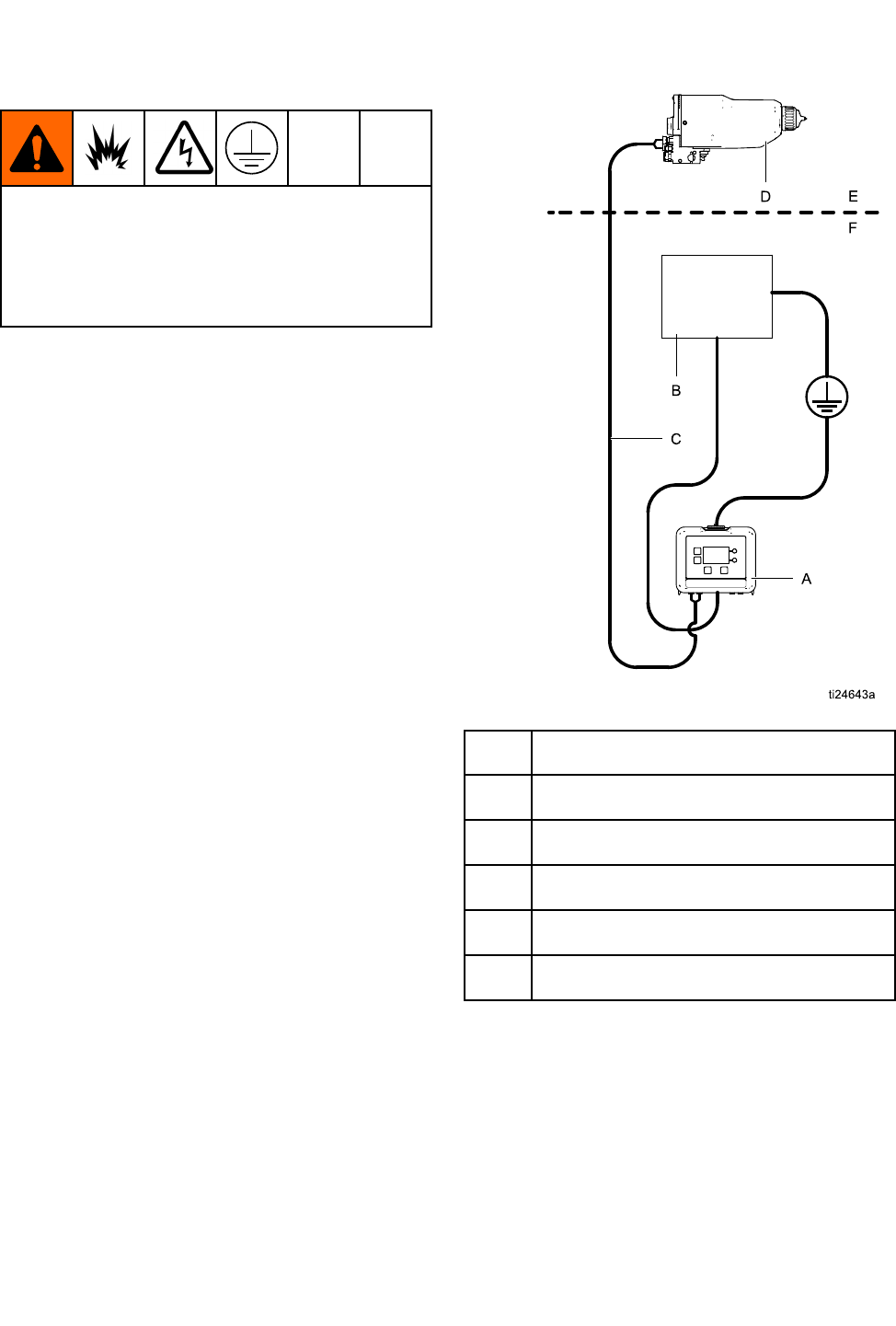
Grounding Grounding
Grounding
Theequipmentmustbegroundedtoreducethe
riskofstaticsparkingandelectricshock.Electric
orstaticsparkingcancausefumestoigniteor
explode.Impropergroundingcancauseelectric
shock.Groundingprovidesanescapewireforthe
electriccurrent.
TheProXpAutoControlModuleisgroundedby
anadapteranda3–wirepowercord(supplied)
connectedtoagroundedelectricaloutlet.Ifthe
moduleismountedtoabracket,connectaseparate
groundwiretothebracketusingascrew.Connect
theotherendtoatrueearthground.
AProXpAutoControlModule
BPowerSupply
CFiberOpticCable
DProXpAutoElectrostaticGun
EHazardousArea
FNon-HazardousArea
332989A 9
Operation
Operation Operation
Operation
Module Module
ModuleScreens Screens
Screens
TheProXpAutoControlModulehastwosetsof
screens:RunandSetup.Fordetailedinformationsee
RunScreens,page16,andSetupScreens,page18.
PresstotogglebetweentheRunscreensand
theSetupscreens.
Preset Preset
Preset
Thepresetscanbeusedtostoregunparameters.
Fourpresetsareavailableforeachgun.See
SetupScreens1and2,page18toviewandchange
presetparameters.
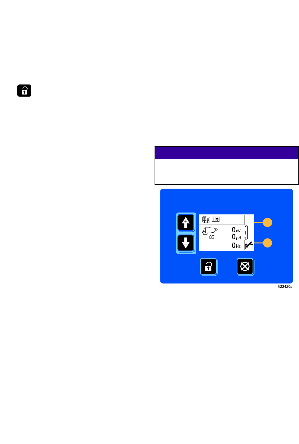
Module Module
ModuleKeys Keys
Keys
Thecontrolmoduledisplayandkeysaredisplayed
below.Table1explainsthefunctionofthemembrane
keysonthecontrolmodule.Asyoumovethrough
thescreens,youwillnoticethatmostinformation
iscommunicatedusingiconsratherthanwords
tosimplifyglobalcommunication.Thedetailed
screendescriptionsinRunScreens,page16,and
SetupScreens,page18,explainwhateachicon
represents.Thetwosoftkeysaremembranebuttons
whosefunctioncorrelateswiththescreencontentto
theimmediateleftofthebutton.
NOTICE NOTICE
NOTICE
Topreventdamagetothesoftkeybuttons,donot
pressthebuttonswithsharpobjectssuchaspens,
plasticcards,orngernails.
Figure4ControlModuleKeypadandDisplay
10 332989A
Operation
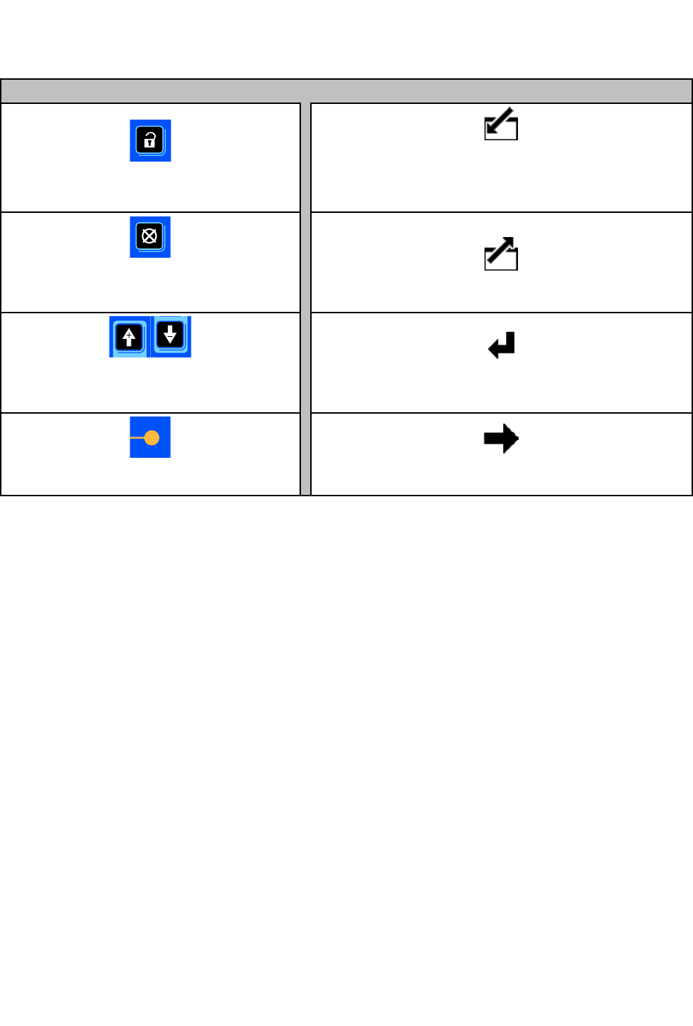
Table Table
Table1 1
1Module Module
ModuleKeys Keys
Keys
Membrane Membrane
MembraneKeys Keys
KeysSoftkeys Softkeys
Softkeys
PresstotogglebetweenRunscreens
andSetupscreens.
Enter Screen.
Highlightdatathatcanbeedited.
AlsochangesthefunctionoftheUp/Down
arrowssotheymovebetweendataeldson
thescreen,ratherthanbetweenscreens.
Error Reset:
Usetocleareventaftercause
hasbeenxed.Alsousedtocanceldata
enteredandreturntooriginaldata.
Exit Screen.
Exitdataediting.
Up/Down Arrows:
Usetomovebetween
screensoreldsonascreen,ortoincrement
ordecrementthedigitsinasettableeld.
Enter.
Presstoactivateaeldforeditingortoaccept
thehighlightedselectiononadropdownmenu.
Softkeys:
Usevariesbyscreen.
Seecolumnsatright.
Right.
Movetotherightwheneditingnumberelds.Press
againtoaccepttheentrywhenalldigitsarecorrect.
332989A
11
Operation
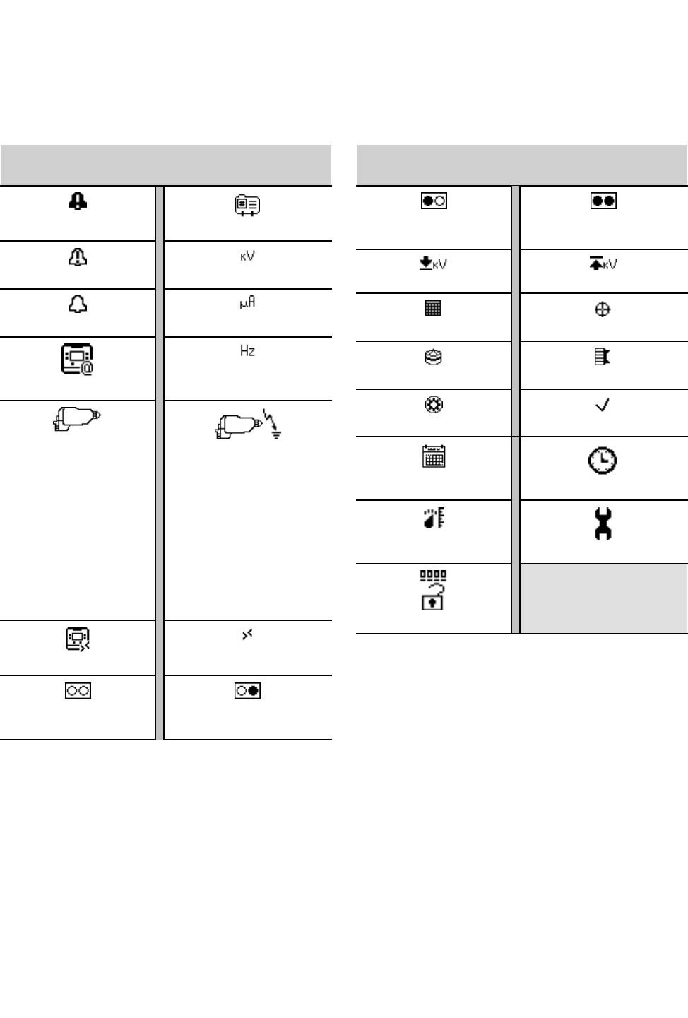
Icons Icons
Icons
Asyoumovethroughthescreens,youwillnoticethatmostinformationiscommunicatedusingiconsrather
thanwordstosimplifyglobalcommunication.ThedetailedscreendescriptionsinRunScreens,page16,and
SetupScreens,page18,explainwhateachiconrepresents.
Screen Screen
ScreenIcons Icons
Icons
AlarmPresetNumber
DeviationkiloVolts/Voltage
AdvisorymicroAmperes/Current
DisplayID
Hertz/Frequency
ElectrostaticGun
Gun1
Gun2
NumberofGuns
ElectrostaticGunActive
RemoteModeRemoteModeEnabled
Preset1ActivePreset2Active
Screen Screen
ScreenIcons Icons
Icons
Preset3ActivePreset4Active
LowkVAlarmSetpointMaximumkVSetpoint
TargetDaysRemainingDays
Tip/NozzleAircap
TurbineCheckMark/Optional
CalendarClock
UnitsMaintenance
Password
12
332989A
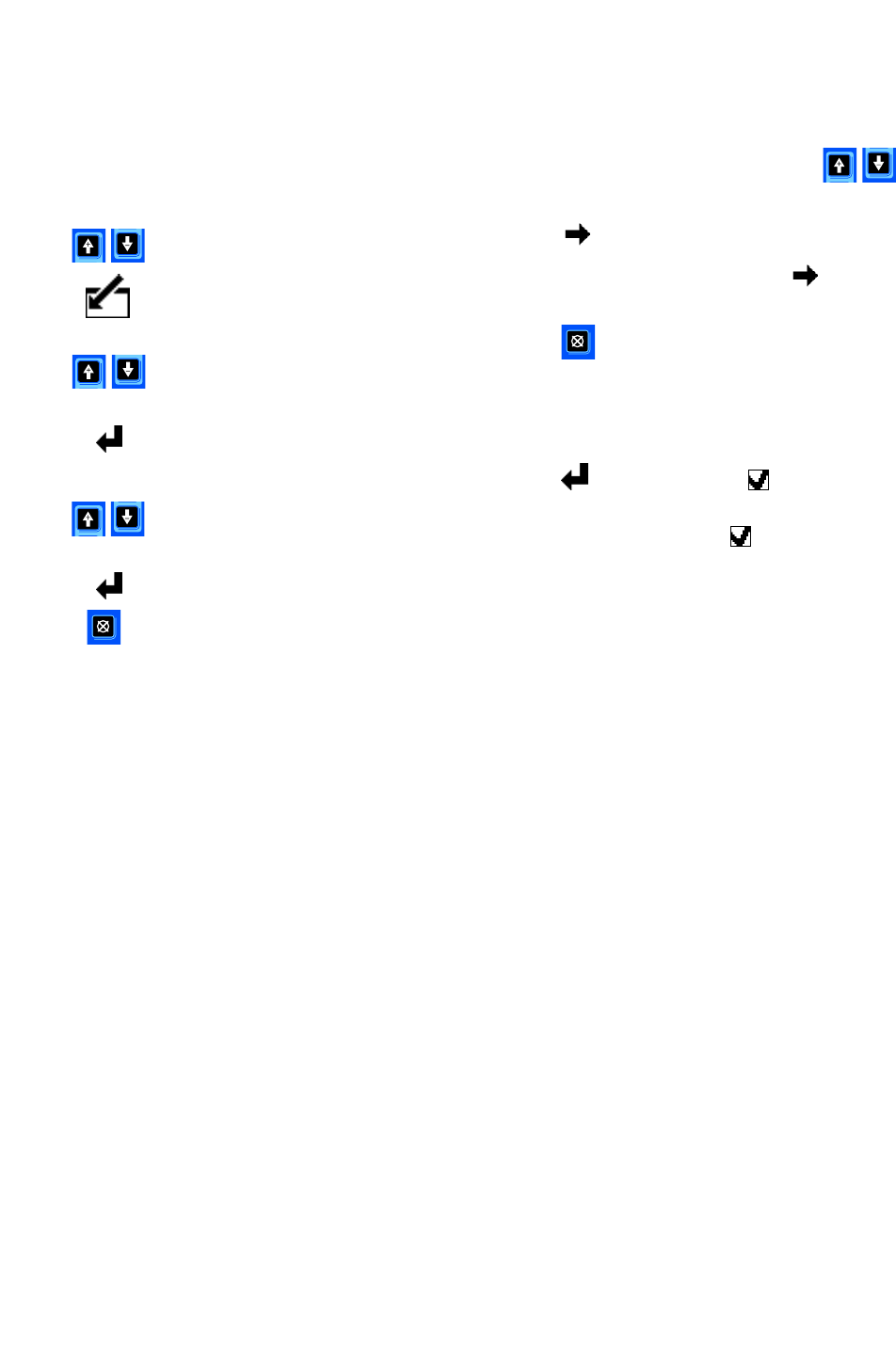
Operation
Screen Screen
ScreenNavigation Navigation
Navigationand and
andEditing Editing
Editing
Refertothissectionifyouhavequestionsabout
screennavigationorabouthowtoenterinformation
andmakeselections.
All All
AllScreens Screens
Screens
1.Usetomovebetweenscreens.
2.Presstoenterascreen.Therstdataeld
onthescreenwillhighlight.
3.Usetohighlightthedatayouwishto
change.
4.Presstoedit.
Drop Drop
DropDown Down
DownField Field
Field
1.Usetohighlightthecorrectchoicefrom
thedropdownmenu.
2.Presstoselect.
3.Presstocancel.
Number Number
NumberField Field
Field
1.Therstdigitwillbehighlighted.Use
tochangethenumber.
2.Presstomovetothenextdigit.
3.Whenalldigitsarecorrect,pressagainto
accept.
4.Presstocancel.
Check Check
CheckBox Box
BoxField Field
Field
Acheckboxeldisusedtoenableordisablefeatures
inthesoftware.
1.Presstotogglebetweenandanempty
box.
2.Thefeatureisenabledifaisinthebox.
332989A 13
Operation
Screen Screen
ScreenMap Map
Map
Run Run
RunScreens Screens
ScreensSetup Setup
SetupScreens Screens
Screens
Run Run
RunScreen Screen
Screen1 1
1, ,
,page page
page16 16
16Setup Setup
SetupScreen Screen
Screen1, 1,
1,page page
page18 18
18
Run Run
RunScreens Screens
Screens2–5 2–5
2–5, ,
,page page
page17 17
17Setup Setup
SetupScreen Screen
Screen2, 2,
2,page page
page18 18
18
(2gunsystemsonly)
Run Run
RunScreens Screens
Screens2–5 2–5
2–5, ,
,page page
page17 17
17Setup Setup
SetupScreen Screen
Screen3, 3,
3,page page
page19 19
19
Run Run
RunScreens Screens
Screens2–5 2–5
2–5, ,
,page page
page17 17
17Setup Setup
SetupScreen Screen
Screen4, 4,
4,page page
page19 19
19
(2gunsystemsonly)
Run Run
RunScreens Screens
Screens2–5 2–5
2–5, ,
,page page
page17 17
17Setup Setup
SetupScreen Screen
Screen5 5
5, ,
,page page
page20 20
20
14
332989A
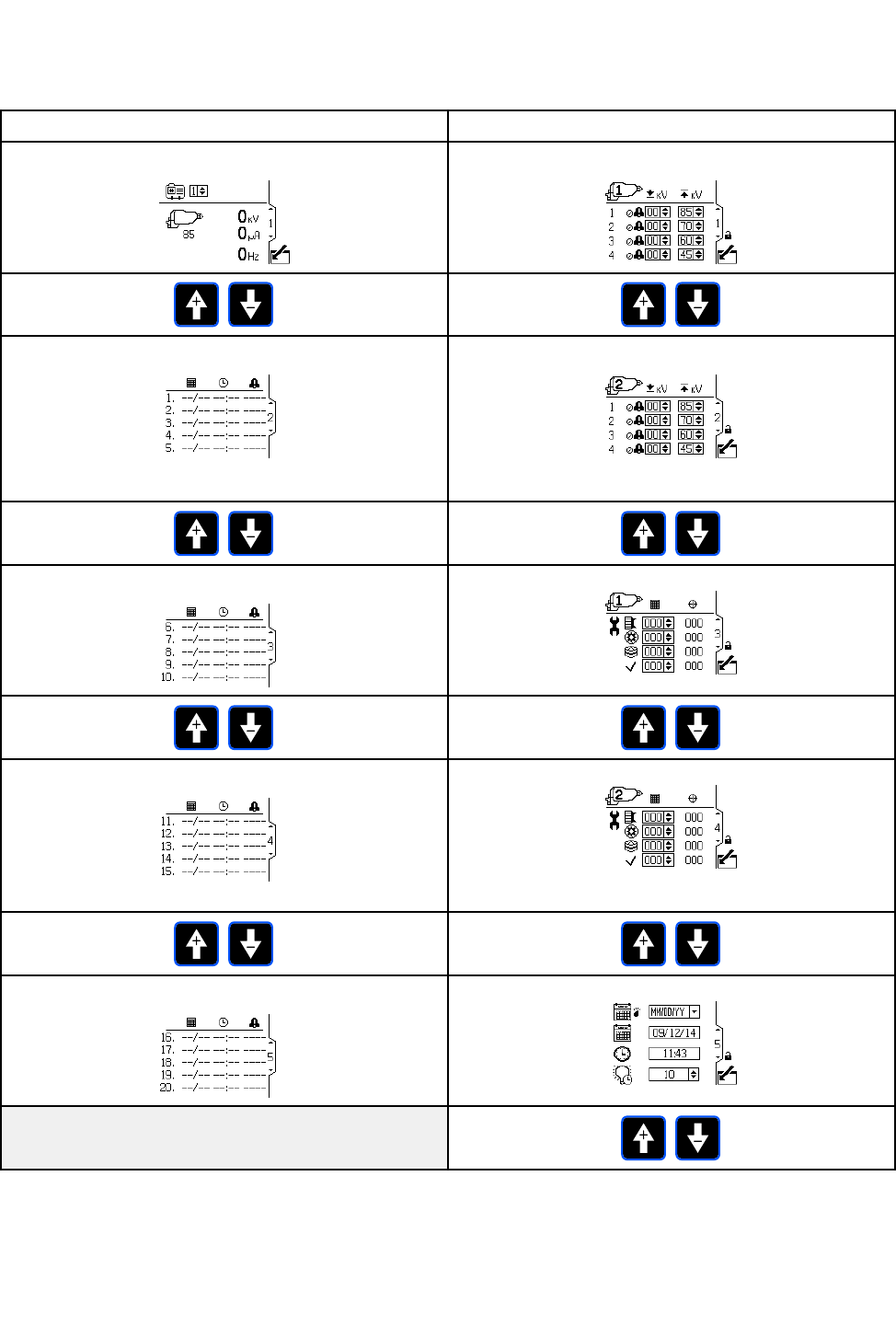
RunScreens
Run Run
RunScreens Screens
Screens
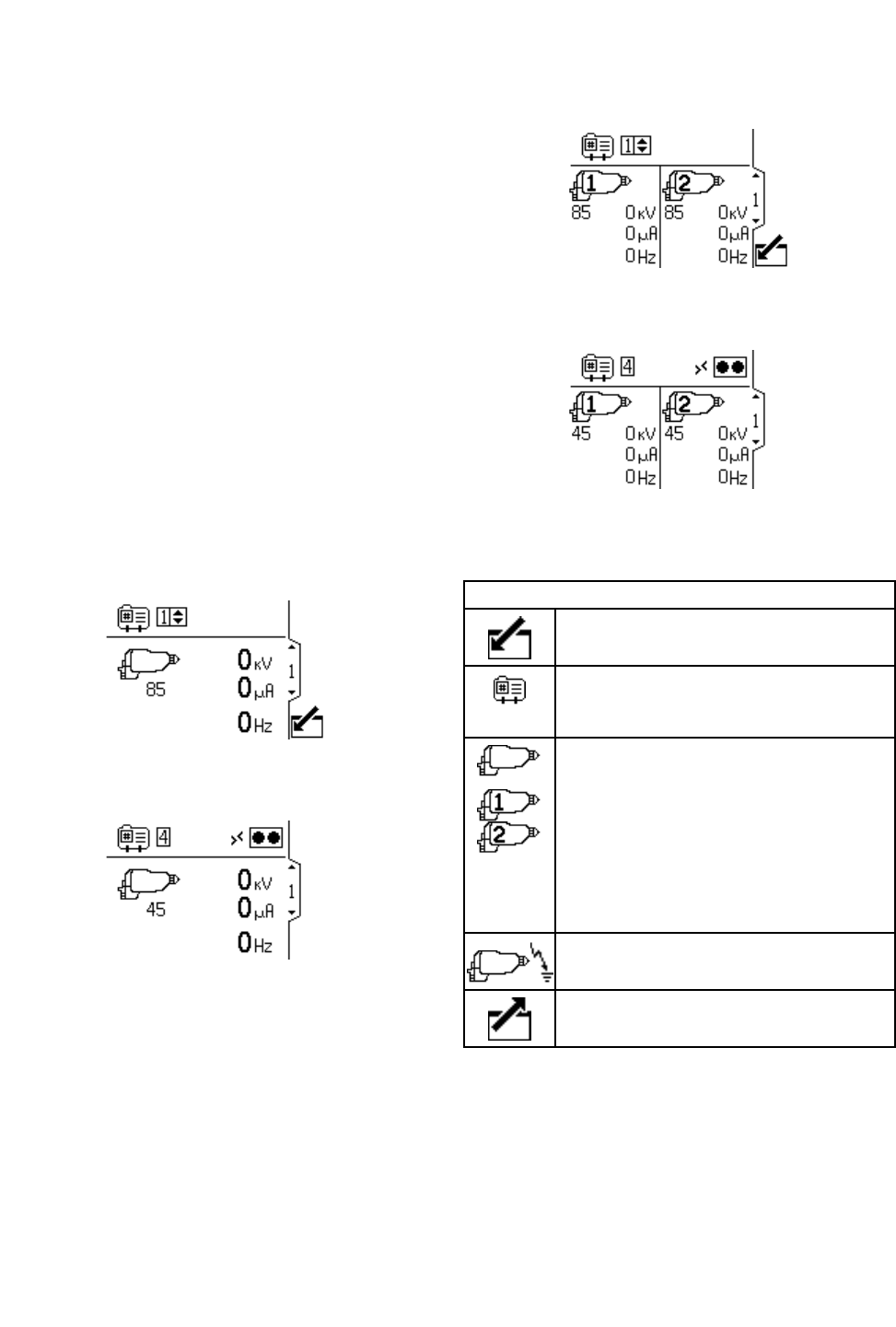
WheninRunMode,thedisplayshowsthegun
parametersandthemostrecent20events.The
activegunpresetcanalsobechanged.
Run Run
RunScreen Screen
Screen1 1
1
Usethisscreentoviewthegunsprayingvoltage
inkilovolts(kV),thesprayingcurrentinmicroamps
(µA),andturbinefrequencyinhertz(Hz).Theactive
maximumsprayingvoltageisshownunderthegun
icon.Theactivegunpresetisoperatorsettableto
presets1-4.Themaximumvoltagesettingforthe
presetscanbechangedonsetupscreen1.Ifthe
deviceisinremotemode,theremotemodeicon
showsupnexttothepresetselectcontrol.When
thegunhasturbinepower,thenumberswillshow
non-zero.Whenintwogunmode,theinformation
forbothgunsisshown.
NOTE: NOTE:
NOTE:Onlyonepresetisselected.Makesureyour
presetsareproperlysetupforbothguns.
Figure5RunScreen1inManualMode(1gun
system)
Figure6RunScreen1inRemoteMode(1gun
system)
Figure7RunScreen1inManualMode(2gun
system)
Figure8RunScreen1inRemoteMode(2gun
system)
Run Run
RunScreen Screen
Screen1 1
1Key Key
Key
Enterthescreentoedit(manualmode
only).
VoltagePreset;operatorselectable.
Changesthemaximumsprayingvoltage
ofthegun.Presets1–4.
ElectrostaticGun.Thenumberbeneath
theiconistheactivemaximumspraying
voltage.
Alsodisplayssprayingvoltage(kV)and
sprayingcurrent(µA).
NOTE: NOTE:
NOTE:Thenumbershowninsidethe
gunisthegunnumber.
ElectrostaticGunActive
Exitthescreen(manualmodeonly).
16 332989A
RunScreens
Run Run
RunScreens Screens
Screens2–5 2–5
2–5
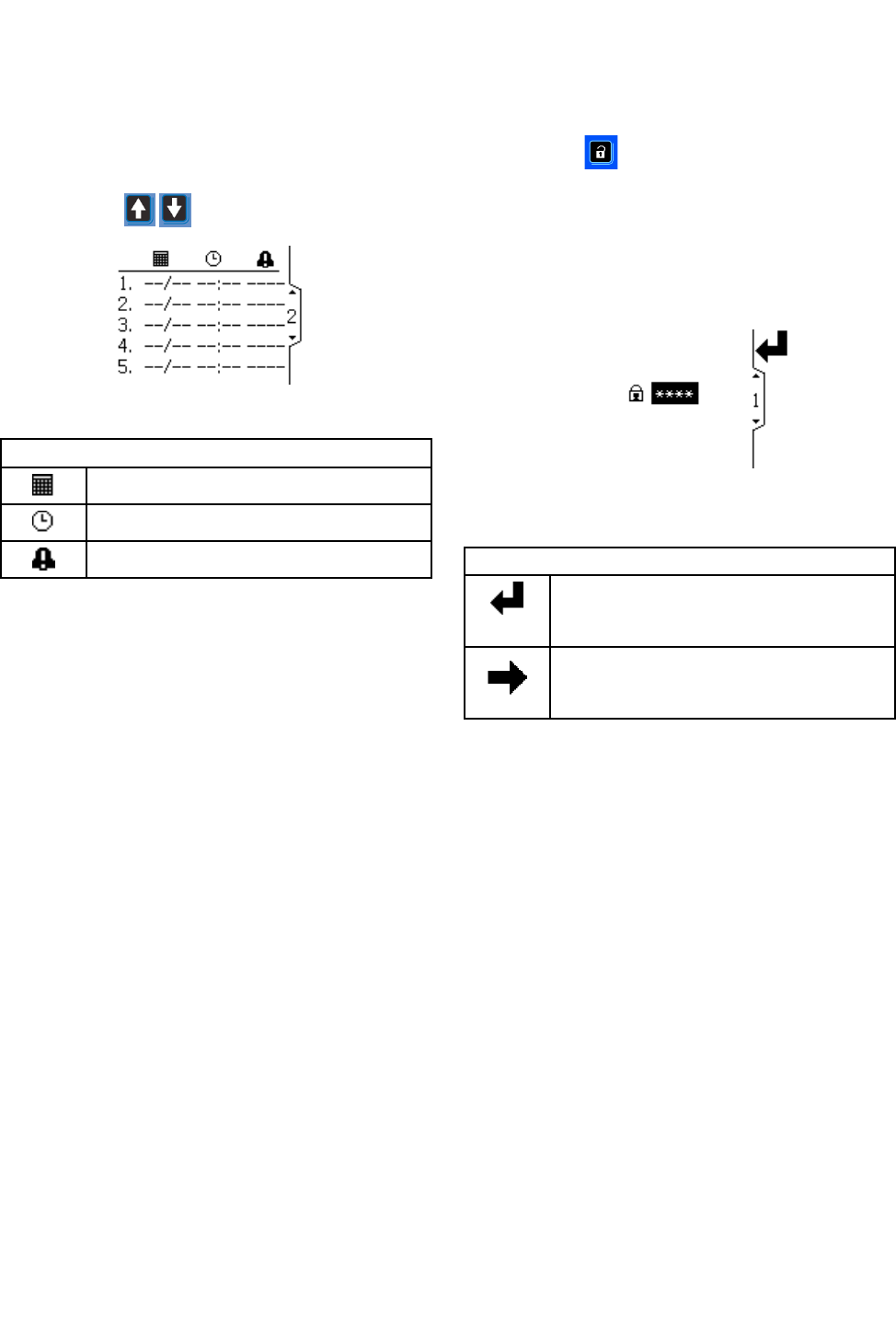
UseRunScreens2-5toviewthelogofrecentevents.
Thelatest20eventsareviewable,withdateandtime.
NOTE: NOTE:
NOTE:RunScreen2isshownasanexample.Use
thearrowkeystoscrollthroughthescreens.
Figure9RunScreen2
Run Run
RunScreen Screen
Screen2 2
2Key Key
Key
Datetheeventoccurred.
Timetheeventoccurred.
Indicatesaneventoccurred.
Password Password
PasswordScreen Screen
Screen
Ifapasswordhasbeenset,thePasswordScreen
displayswhenispressedfromanyRunscreen.
EnterpasswordtoenableentrytotheSetupscreens.
Setthepasswordto0000todisablepassword
protection.SeeSetupScreens3and4,page19to
setorchangethepassword.
NOTE: NOTE:
NOTE:Ifyouforgetyourpassword,use1492togain
accessandenteranewpassword.
Figure10PasswordScreen
Key Key
Key
Presstoactivateaeldforeditingor
toacceptthehighlightedsectionona
dropdownmenu.
Movetotherightwheneditingnumber
elds.Pressagaintoaccepttheentry
whenalldigitsarecorrect.
332989A
17
SetupScreens
Setup Setup
SetupScreens Screens
Screens
TheSetupModeisusedtosetupapassword
(ifdesired)andtosetparametersforcontrolling
andmonitoringtheelectrostaticgun.See
ScreenNavigationandEditing,page13for
informationonhowtomakeselectionsandenter
data.
Setup Setup
SetupScreens Screens
Screens1 1
1and and
and2 2
2
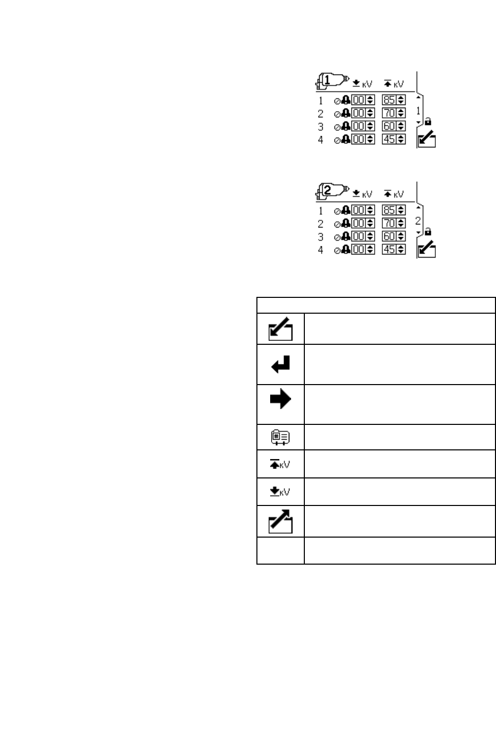
Usethisscreentoviewandchangepreset
parameters.Presetscanbeusedtostoregun
parameters.Fourpresetsareavailableforeachgun.
•Therstcolumnshowsthepresetnumber(1-4).
•Thesecondcolumnshowstheminimumvoltage
setpointforthepreset,settable(inincrementsof5)
between0and50kVforan85kVgunandbetween
0and40fora60kVgun.Ifthesprayingvoltage
fallsbelowthesetvalue,thesystemwillalarm.
Settingthecontroltozerodisablesthealarm.
•Thethirdcolumnshowsthemaximumvoltagefor
thepreset,settablebetween40kVand85kV(in
incrementsof5).Settingtoanythingotherthan
85kVputsthegunintoalowvoltagemode.For
waterborneguns,voltageissettablebetween30
kVand60kV.
•NOTE: NOTE:
NOTE:An85kVgun’snormalhighvoltagereading
is60–70kV.Ifaballendhighvoltagemeasurement
probeisused,thegunvoltagewillrisetoabout85
kV.Thiswillhappenwithallresistiveelectrostatic
guns.
•Intwogunoperation,asecondscreenisshownfor
Gun#2asindicatedbytheguniconintheupper
leftportionofthescreen.
Figure11SetupScreen1
Figure12SetupScreen2(2gunsystemonly)
Setup Setup
SetupScreen Screen
Screen1 1
1Key Key
Key
Enterthescreen.
Presstoactivateaeldforeditingorto
acceptthehighlightedselectionona
dropdownmenu.
Movetotherightwheneditingnumber
elds.Pressagaintoaccepttheentry
whenalldigitsarecorrect.
Presetnumber.
Setthemaximumvoltagesetpointfor
thepreset.
Settheminimumvoltageforthelow
voltagealarmforthepreset.
Exitdataediting.
Denoteswhichgunthesettingsbelongto
18 332989A
SetupScreens
Setup Setup
SetupScreens Screens
Screens3 3
3and and
and4 4
4
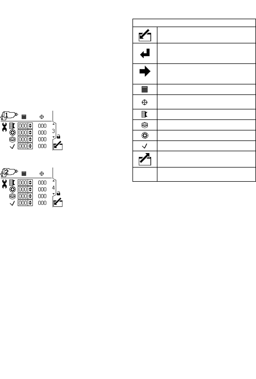
Usethisscreentoviewandresetthemaintenance
totalizers.Maintenancetotalizerunits,shownonthis
SetupScreen,arealwaysinelapsedcalendardays.
AnAdvisoryisissuedwhenthemaintenancetotalizer
reacheszero.Torestartthetimer,navigatetothis
screen,editthesetpoint,andthencleartheadvisory
usingtheErrorResetbutton.Asthesetimersare
basedonthedisplaydate,themaintenancetotalizers
mustberesetifthedateischanged.Intwogun
operation,asecondscreenisshownforGun#2as
indicatedbytheguniconintheupperleftportionof
thescreen.
Figure13SetupScreen3
Figure14SetupScreen4(2gunsystemonly)
Setup Setup
SetupScreen Screen
Screen3 3
3and and
and4 4
4Key Key
Key
Enterthescreen.
Presstoactivateaeldforeditingorto
acceptthehighlightedselectionona
dropdownmenu.
Movetotherightwheneditingnumber
elds.Pressagaintoaccepttheentry
whenalldigitsarecorrect.
Maintenancesetpointincalendardays.
Maintenancetotalizer–Countsdown
fromsetpointtozero.
Aircapmaintenancetotalizer.
Tip/Nozzlemaintenancetotalizer.
Alternatormaintenancetotalizer.
Check/Optionalmaintenancetotalizer
Exitdataediting.
Denoteswhichgunthesettingsbelongto
332989A 19
SetupScreens
Setup Setup
SetupScreen Screen
Screen5 5
5
Usethisscreentosetdateformat,date,time,and
backlighttimeout.
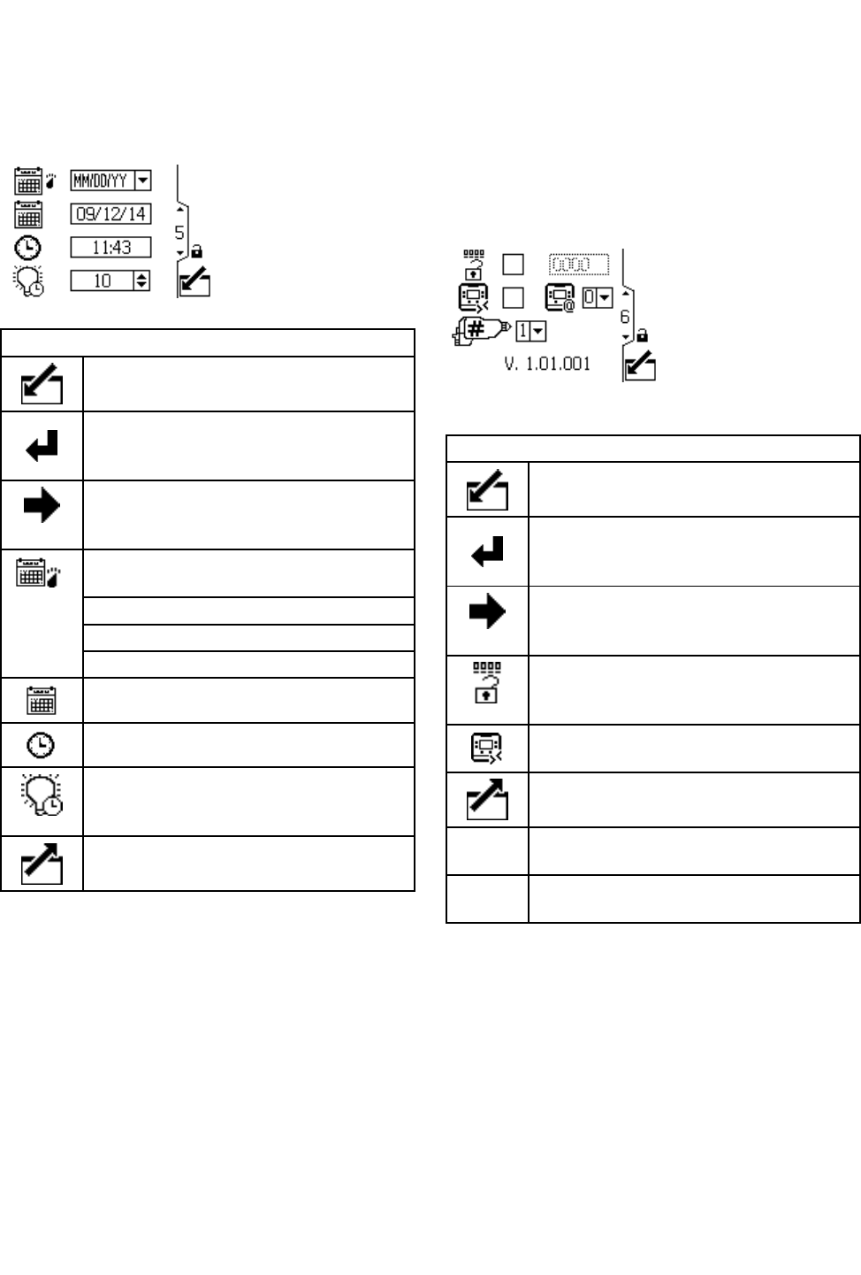
Figure15SetupScreen5
Setup Setup
SetupScreen Screen
Screen5 5
5Key Key
Key
Enterthescreen.
Presstoactivateaeldforeditingorto
acceptthehighlightedselectionona
dropdownmenu.
Movetotherightwheneditingnumber
elds.Pressagaintoaccepttheentry
whenalldigitsarecorrect.
Selectyourpreferreddateformatfrom
thedropdownmenu.
MM/DD/YY
DD/MM/YY
YY/MM/DD
Setthecurrentdate.
Setthecurrenttime.
Setthedisplaybacklighttimeout(in
minutes).Asettingofzeromeansthat
thebacklightisoncontinuously.
Exitdataediting.
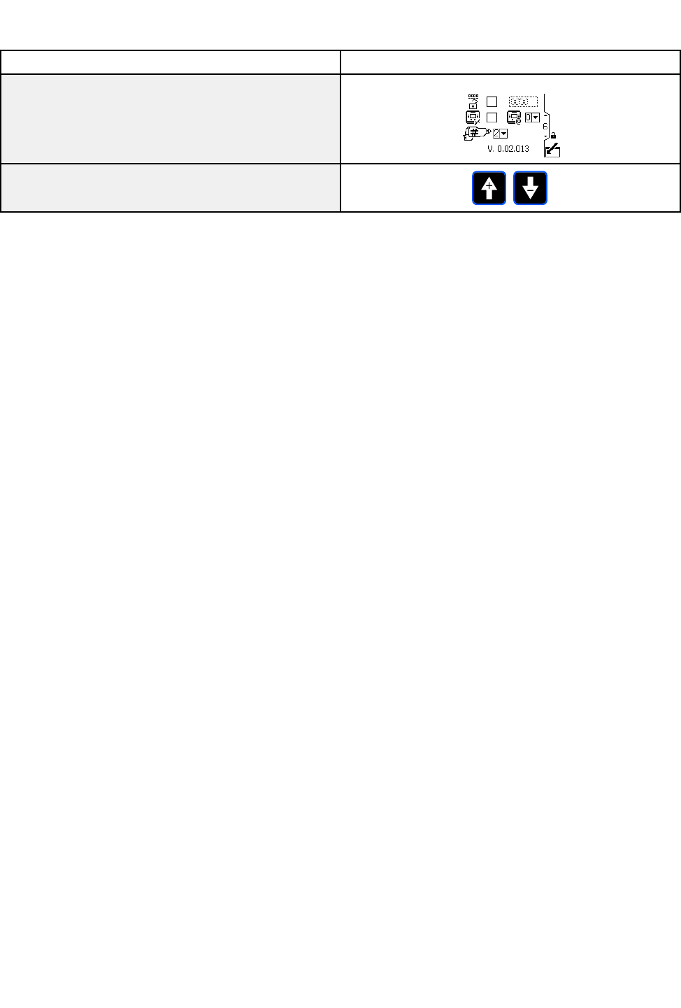
Setup Setup
SetupScreen Screen
Screen6 6
6
Usethisscreentoactivateorchangeapassword
thatwillberequiredtoaccesstheSetupscreens
andtoenable/disableremotevoltagepresetcontrol.
Thisscreenalsodisplaysthesoftwareversion.This
screenisalsousedtoselectthenumberofgunsfor
thesystem(1or2).
Figure16SetupScreen6
Setup Setup
SetupScreen Screen
Screen6 6
6Key Key
Key
Enterthescreen.
Presstoactivateaeldforeditingorto
acceptthehighlightedselectionona
dropdownmenu.
Movetotherightwheneditingnumber
elds.Pressagaintoaccepttheentry
whenalldigitsarecorrect.
Enable/Disablethepasswordwiththe
checkboxcontrol.Enterthedesired
password(ifenabled).
Enable/Disableremotevoltagepreset
control.
Exitdataediting.
Choos1fora1gunsystem,2fora2
gunsystem.
DisplayIDsetting.Foradvanced
installationsonly.
20 332989A
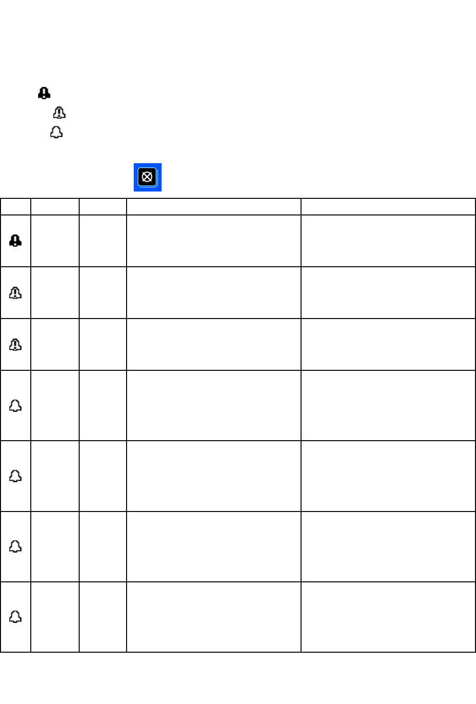
EventCodeTroubleshooting
Event Event
EventCode Code
CodeTroubleshooting Troubleshooting
Troubleshooting
Eventcodescantakefourforms:
•Alarm:criticalevent;mustbeaddressedimmediately.
•Deviation:criticalevent;requiresattention.
•Advisory:non-criticalevent;requiresattention.
•Record:Usefulinformationfortroubleshooting.
Toclearaneventcode,press.
Icon Icon
IconCode Code
CodeGun Gun
GunDescription Description
DescriptionHow How
Howto to
toCorrect Correct
Correctand and
andClear Clear
Clear
V1D1
V1D2
Gun1
Gun2
Low Low
LowkV kV
kVAlarm. Alarm.
Alarm.
ThelowkValarmdisplayswhen
thesprayingvoltagedropsbelow
theuser-setminimum.
Decreaseconductivityofpaintor
increasedistancetopart.
Pressclearbuttontoclearalarm.
CBD1
CBD2
Gun1
Gun2
Fiber Fiber
FiberOptic Optic
OpticCommunication Communication
CommunicationDeviation. Deviation.
Deviation.
Theberopticcommunicationalarm
displayswhenthedisplayreceives
baddatafromthegun.
Checkberopticcablesandgun
power.
Pressclearbuttontoclearalarm.
CAI1
CAI2
Gun1
Gun2
Power Power
PowerSupply Supply
SupplyCommu- Commu-
Commu-
nication nication
nicationLost Lost
LostDeviation. Deviation.
Deviation.
Thegunberopticboardlosescom-
municationwiththegunpowersupply.
Checkinternalgunconnectionsand
verifyturbineairpressure.
Pressclearbuttontoclearalarm.
MD11
MD21
Gun1
Gun2
Turbine Turbine
TurbineMaintenance Maintenance
MaintenanceAdvisory. Advisory.
Advisory.
Theturbinemaintenancetotalizer
targetvaluewasreached.
Performmaintenanceandreset
maintenancetotalizer.
Pressclearbuttontoclearalarm.
Alarmwillnotclearuntilmaintenance
totalizerhasbeenreset.
MD12
MD22
Gun1
Gun2
Tip/Nozzle Tip/Nozzle
Tip/NozzleMaintenance Maintenance
MaintenanceAdvisory. Advisory.
Advisory.
Thetip/nozzlemaintenancetotalizer
targetvaluewasreached.
Performmaintenanceandreset
maintenancetotalizer.
Pressclearbuttontoclearalarm.
Alarmwillnotclearuntilmaintenance
totalizerhasbeenreset.
MD13
MD23
Gun1
Gun2
Aircap Aircap
AircapMaintenance Maintenance
MaintenanceAdvisory. Advisory.
Advisory.
Theaircapmaintenancetotalizer
targetvaluewasreached.
Performmaintenanceandreset
maintenancetotalizer.
Pressclearbuttontoclearalarm.
Alarmwillnotclearuntilmaintenance
totalizerhasbeenreset.
MD14
MD24
Gun1
Gun2
Check/Optional Check/Optional
Check/OptionalMain- Main-
Main-
tenance tenance
tenanceAdvisory. Advisory.
Advisory.
Thecheck/optionalmaintenance
totalizertargetvaluewasreached.
Performmaintenanceandreset
maintenancetotalizer.
Pressclearbuttontoclearalarm.
Alarmwillnotclearuntilmaintenance
totalizerhasbeenreset.
332989A
21
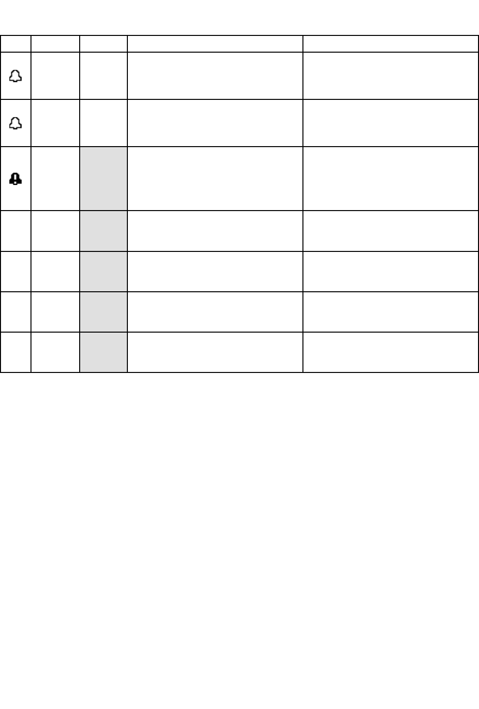
EventCodeTroubleshooting
Icon Icon
IconCode Code
CodeGun Gun
GunDescription Description
DescriptionHow How
Howto to
toCorrect Correct
Correctand and
andClear Clear
Clear
K2D1
K2D2
Gun1
Gun2
Turbine Turbine
TurbineFrequency Frequency
FrequencyLow Low
LowAdvisory. Advisory.
Advisory.
Turbinefrequencybelow400Hzat
85kVorbelow325Hzatlowervoltage.
Increaseturbineairpressure.
Pressclearbuttontoclearalarm.
K3D1
K3D2
Gun1
Gun2
Turbine Turbine
TurbineFrequency Frequency
FrequencyHigh High
HighAdvisory. Advisory.
Advisory.
Turbinefrequencyabove750Hzat
85kVorabove675Hzatlowervoltage.
Decreaseturbineairpressure.
Pressclearbuttontoclearalarm.
WMC1
Invalid Invalid
InvalidHardware Hardware
Hardware
Theinvalidhardwarealarmdisplays
whenthedisplaycontrolmodule
isnotthecorrectversiontowork
withtheProXpAuto.
Verifytheproperdisplaycontrol
modulepartnumberisbeingused.
Seepartspageforvalidpartnumbers.
EAD1Preset Preset
Preset1 1
1Activated Activated
ActivatedRecord. Record.
Record.
Thisrecordshowswhenpreset
1wasactivated.
Noactionrequired.Shownonthe
eventlogforinformationonly.
EAD2Preset Preset
Preset2 2
2Activated Activated
ActivatedRecord. Record.
Record.
Thisrecordshowswhenpreset
2wasactivated.
Noactionrequired.Shownonthe
eventlogforinformationonly.
EAD3Preset Preset
Preset3 3
3Activated Activated
ActivatedRecord. Record.
Record.
Thisrecordshowswhenpreset
3wasactivated.
Noactionrequired.Shownonthe
eventlogforinformationonly.
EAD4Preset Preset
Preset4 4
4Activated Activated
ActivatedRecord. Record.
Record.
Thisrecordshowswhenpreset
4wasactivated.
Noactionrequired.Shownonthe
eventlogforinformationonly.
22
332989A

Troubleshooting
Troubleshooting Troubleshooting
Troubleshooting
Problem Problem
ProblemCause Cause
CauseSolution Solution
Solution
Powerisnoton.Turnpowersupplyon. Displayiscompletelydark.
Looseordisconnectedpower
cable.
Tightenorconnectcable.
Incorrectberopticcable
connections.
Checkconnections.See
FiberOpticConnections,page7.
Badberopticcable.Checkcablefordamage.Replace
orrepairberopticcable.See
FiberOpticCableRepair,page25
Gunisonbutnonumbersare
showing.
Gunboarderror.Turnoffturbineair,thenturnback
ontocyclepowertogunboard.
ClockstopsfunctioningDeadbattery.Replacebattery.See
ReplaceBattery,page24
Displayhaspowerbutdoesnot
function.
Hardwarefailure.Replacedisplaymodule.
Diagnostic Diagnostic
DiagnosticInformation Information
Information
TheLEDsonthebottomofthecontrolmodulegiveimportantinformationaboutsystemfunction.
LED LED
LEDSignals Signals
Signals
Signal Signal
SignalDescription Description
Description
GreenOnControlmoduleispoweredup.
YellowInternalcommunicationinprogress.
RedsolidControlmodulefailure.SeeTroubleshooting,page23.
RedashingSoftwareisupdating.
RedashingslowlyTokenerror;removetokenanduploadsoftwaretokenagain.
332989A 23
Maintenance
Maintenance Maintenance
Maintenance
Update Update
UpdateSoftware Software
Software
Manual3A1244willaccompanyanynecessary
softwareupdates.FollowallinstructionsinManual
3A1244toupdateyourcontrolmodulesoftware.
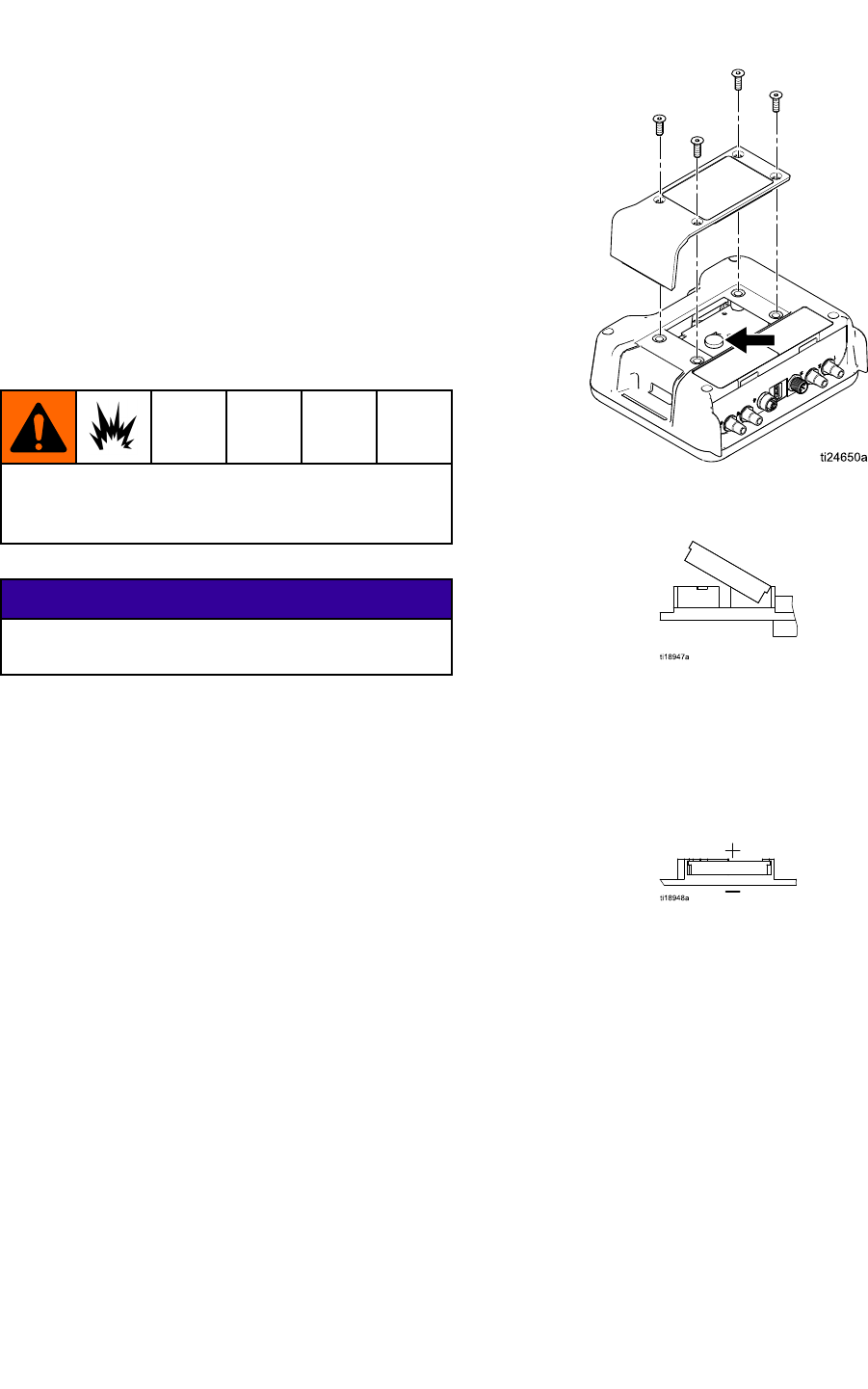
Replace Replace
ReplaceBattery Battery
Battery
Replacethebatteryonlyiftheclockstopsfunctioning
afterdisconnectingpowerorapowerfailure.
Sparkingcanoccurwhenchangingthebattery.
Replacethebatteryonlyinanon-hazardous
location,awayfromammableuidsorfumes.
NOTICE NOTICE
NOTICE
Toavoiddamagingthecircuitboard,weara
groundingstrap.
1.Disconnectpower.
2.Removethemodulefromthebracket.
3.Attachgroundingstrap.
4.Remove4screws,andthenremovetheaccess
cover.
5.Useaatheadscrewdrivertopryouttheold
battery.
NOTE: NOTE:
NOTE:Disposeofbatteryproperlyinan
approvedcontainerandaccordingtoapplicable
localguidelines.
6.Replacewithnewbattery.Ensurebatteryts
underconnectortabsbeforesnappingotherend
inplace.
NOTE: NOTE:
NOTE:UseonlyPanasonicCR2032batteriesfor
replacement.
7.Reassembleaccesscoverandscrews.
8.Snapthemodulebackintothebracket.
24
332989A
Repair
Repair Repair
Repair
Fiber Fiber
FiberOptic Optic
OpticCable Cable
CableRepair Repair
Repair
NOTE NOTE
NOTE:Fiberopticrepairkit24W875includesttings
foronedoublestrandberopticcableandacutter
tool.Cuttertool24W823mayalsobepurchased
separately.
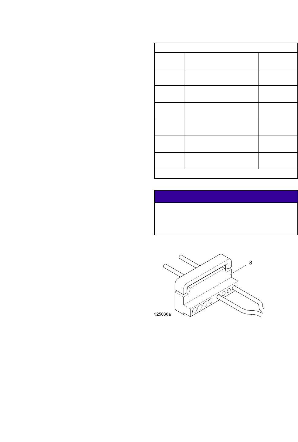
1.Makeacleancuttotheendsofthecableusing
beropticcuttertool(8).Ensuretheendsofthe
cableareequallength.
2.Addberopticttingparts(2)tocableasshown.
Keeptrackofmountingendsusingberoptic
markers(4,5).
3.FortheendofthecablethatconnectstothePro
XpAutoControlModuleortoabulkhead,thread
onberopticnut(3)tolengthAequaling.31in
(5/16”)(7.9mm).
4.FortheendofthecablethatconnectstothePro
XpAutogun,thelengthmustbeadjustedfor
yourgunmodel.Forrearmanifoldgunmodels
(modelnumbersLA1xxxorHA1xxx)adjust
lengthAto.31in(7.9mm).Forbottommanifold
gunmodels(modelnumbersLA2xxxorHA2xxx)
adjustlengthAto1.02in(25.9mm).
WhenusingaGracoprovidedcable,DimensionA
issetatthefactory.
Fiber Fiber
FiberOptic Optic
OpticCable Cable
CableConnector Connector
ConnectorAdjustment Adjustment
Adjustment
FOCable
Kit
DescriptionDimensionA
24X003uFiberOpticCable,Rear
Manifold,25ft
0.31in
(7.9mm)
24X004uFiberOpticCable,Rear
Manifold,50ft
0.31in
(7.9mm)
24X005uFiberOpticCable,Rear
Manifold,100ft
0.31in
(7.9mm)
24X006uFiberOpticCable,Bottom
Manifold,25ft
1.02in
(25.9mm)
24X007uFiberOpticCable,Bottom
Manifold,50ft
1.02in
(25.9mm)
24X008uFiberOpticCable,Bottom
Manifold,100ft
1.02in
(25.9mm)
u
Cuttertool24W823isincludedinthesecablekits.
NOTICE NOTICE
NOTICE
Fiberopticcableendsmustbecutcleanand
squaretoensureproperfunction.DimensionA
mustbeadjustedforthegunmodelusedtoensure
properfunction.
332989A 25
Repair
Fiber Fiber
FiberOptic Optic
OpticBulkhead Bulkhead
BulkheadInstallation Installation
Installation
Stainless Stainless
StainlessSteel Steel
SteelBulkhead Bulkhead
Bulkhead
AcceptsGracoberopticcablettings.Fits1/2inch
(13mm)panelhole.
24W876 24W876
24W876Stainless Stainless
StainlessSteel Steel
SteelBulkhead Bulkhead
BulkheadInstallation Installation
Installation
1.Drilla1/2in.to9/16in(12.7mmto14.2mm)
holeinboothwallorpaneltoallowbulkheadto
passthrough.
2.Makesureberopticcablesmeetdimensionsas
outlinedinberopticrepairinstructions.
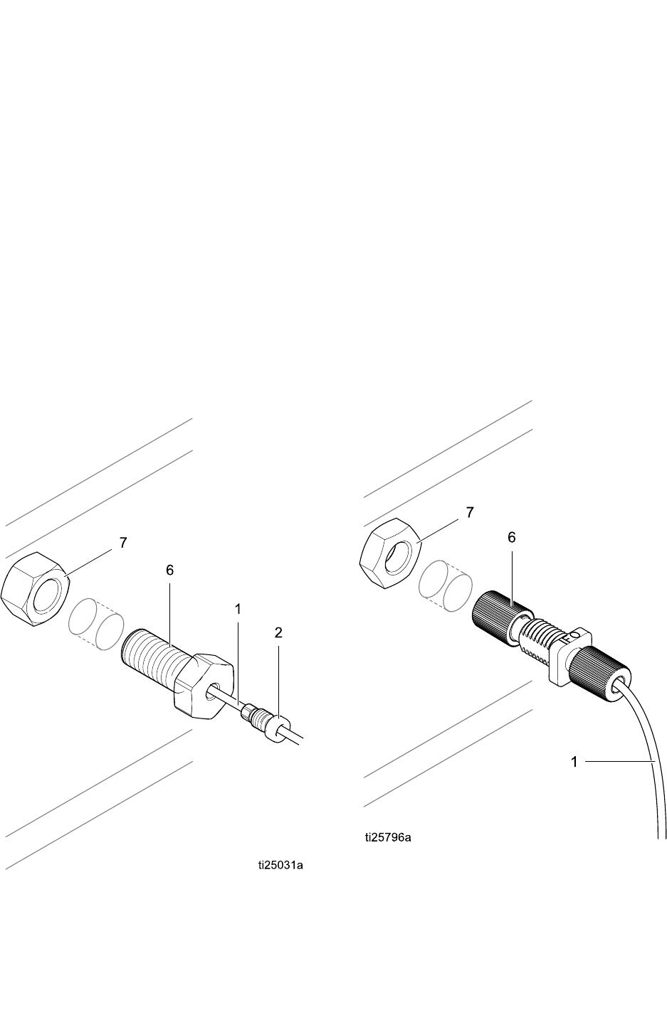
3.Insertbulkhead(6)intoholeandattachnut
(7)oneitherside.Threadinberopticcable
tting(2)untilitbottomsout.Donotforcecable
further.Makesurecablemarkernumbersmatch
toensurepropercommunication.
4.Repeatforsecondsideofcommunications.
Plastic Plastic
PlasticBulkhead Bulkhead
Bulkhead
Acceptsbareberopticcable.Fits5/15”(8mm)
panelhole.
24W877 24W877
24W877Plastic Plastic
PlasticBulkhead Bulkhead
BulkheadInstallation Installation
Installation
1.Drilla5/16in.to3/8in(7.9mmto9.5mm)hole
inboothwallorpaneltoallowbulkheadtopass
through.
2.Makeacleancuttotheendsofthecableusing
beropticcuttertool(8).Ensuretheendsofthe
cableareequallength.
3.Insertbulkhead(6)intoholeandattachnut(7)
oneitherside.Insertcableintobulkheadand
tightencinchnutdowntoasnugt.
4.Repeatforsecondsideofcommunications.
26 332989A
Parts
Parts Parts
Parts
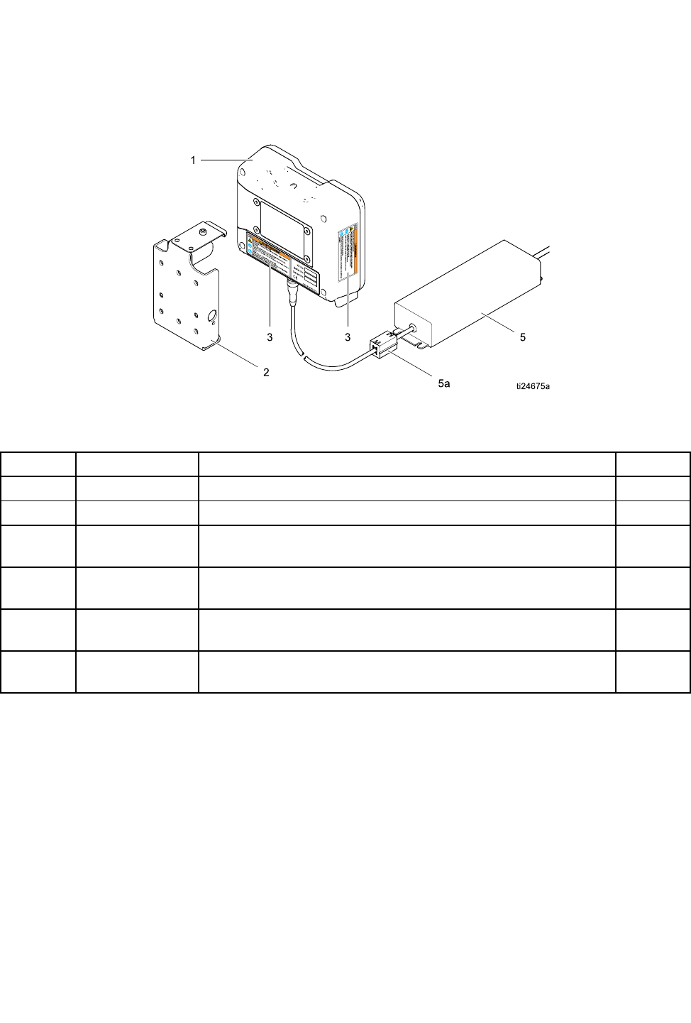
24W035 24W035
24W035— —
—Pro Pro
ProXp Xp
XpAuto Auto
AutoControl Control
ControlModule Module
ModuleKit Kit
Kit
Figure17
Ref. Ref.
Ref.Part Part
PartDescription Description
DescriptionQty. Qty.
Qty.
1 1
124X216 24X216
24X216Pro Pro
ProXp Xp
XpAuto Auto
AutoControl Control
ControlModule Module
Module1 1
1
2 2
2277853 277853
277853Mounting Mounting
MountingBracket Bracket
Bracket1 1
1
3 3
3s
16P265 16P265
16P265Warning Warning
WarningLabel Label
Label1 1
1
5 5
524W880 24W880
24W880Power Power
PowerSupply Supply
Supplywith with
withCord Cord
CordSet Set
Set1 1
1
5a 5a
5a119253 119253
119253Ferrite Ferrite
Ferrite1 1
1
6 6
6244524 244524
244524Ground Ground
GroundWire Wire
WireAssembly Assembly
Assembly(not (not
(notshown) shown)
shown)1 1
1
s
Replacement Danger and Warning labels, tags, and cards are available at no cost.
NOTE: NOTE:
NOTE:ThepowersupplyhasaIEC320–C13maleconnectorforapowercord.ANorthAmericanpowercord
withaNEMA5–15Pplugisincluded.AUSpowercableisprovidedwithkits24W035and34W880.Contact
yourlocalsalespersonifaglobalpowercableisrequired.
332989A
27

Accessories
Accessories Accessories
Accessories
Fiber Fiber
FiberOptic Optic
OpticCables Cables
Cablesfor for
forGun Gun
Gun
Models Models
ModelsWith With
WithRear Rear
RearManifolds Manifolds
Manifolds(Model (Model
(Modelnumbers numbers
numbers
LA1xxx LA1xxx
LA1xxxor or
orHA1xxx) HA1xxx)
HA1xxx)
Kit Kit
KitNumber Number
NumberDescription Description
Description
24X003FiberOpticCable,RearManifold,
25ft
24X004FiberOpticCable,RearManifold,
50ft
24X005FiberOpticCable,RearManifold,
100ft
Models Models
ModelsWith With
WithBottom Bottom
BottomManifolds Manifolds
Manifolds(Model (Model
(Modelnumbers numbers
numbers
LA2xxx LA2xxx
LA2xxxor or
orHA2xxx) HA2xxx)
HA2xxx)
Kit Kit
KitNumber Number
NumberDescription Description
Description
24X006FiberOpticCable,BottomManifold,
25ft
24X007FiberOpticCable,BottomManifold,
50ft
24X008FiberOpticCable,BottomManifold,
100ft
Fiber Fiber
FiberOptic Optic
OpticCable Cable
CableRepair Repair
Repairand and
and
Accessories Accessories
Accessories
Kit Kit
KitNumber Number
NumberDescription Description
Description
24W875FiberOpticRepairKit—
Includesttingsforone
double-strandberoptic
cableandacuttertool.
24W876FiberOpticBulkhead
Fitting,SST—Qty2.
AcceptsGracoberoptic
cablettings.Fits1/2inch
(13mm)panelhole.
24W877FiberOpticBulkhead,
Plastic—Qty.2.
Acceptsbareberoptic
cable.Fits5/16inch(8mm)
panelhole
24W823FiberOpticCutterTool—
Qty.3.
24X009MarkerNumbersforFiber
OpticCableEnds—Pack
of30(#1and#2)
Control Control
ControlModule Module
ModuleI/O I/O
I/OCable Cable
CableAccessory Accessory
Accessory
Kits Kits
Kits
Kit Kit
KitNumber Number
NumberDescription Description
Description
24W881I/Ocable,50ft
24W882I/Ocable,100ft
28 332989A
MountingDimensions
Mounting Mounting
MountingDimensions Dimensions
Dimensions
A A
A
Overall Overall
OverallWidth Width
Width
in.(mm)
B B
B
Overall Overall
OverallHeight Height
Height
in.(mm)
Overall Overall
Overall
Depth Depth
Depth
in.(mm)
Mounting Mounting
MountingDimensions Dimensions
Dimensions
Width Width
Width(C) (C)
(C)x x
xHeight Height
Height(D) (D)
(D)
in.(mm)
E E
E
Mounting Mounting
Mounting
Hole Hole
HoleSize Size
Size
in.(mm)
7.2(183)6.0(152)2.8(71)2.5x3.0(64x76)0.28(7)
Technical Technical
TechnicalData Data
Data
US US
USMetric Metric
Metric
OperatingTemperature32°to122°F0°to50°C
StorageTemperature–22°to140°F–30°to60°C
Weight
ControlModule1lb0.45kg
MountingBracket1lb0.45kg
PowerConnectionStraightIEC320–C13maleconnectorandaNorthAmerican
NEMA5–15Pmaleplugareprovided.
ExternalPowerRequirements100–240Vac,50/60Hz,0.8amps
Humidity0to95percent,non-condensing
Displayhousingissolventresistant.
332989A 29

Graco Graco
GracoStandard Standard
StandardWarranty Warranty
Warranty
GracowarrantsallequipmentreferencedinthisdocumentwhichismanufacturedbyGracoandbearingits
nametobefreefromdefectsinmaterialandworkmanshiponthedateofsaletotheoriginalpurchaserfor
use.Withtheexceptionofanyspecial,extended,orlimitedwarrantypublishedbyGraco,Gracowill,fora
periodoftwelvemonthsfromthedateofsale,repairorreplaceanypartoftheequipmentdetermined
byGracotobedefective.Thiswarrantyappliesonlywhentheequipmentisinstalled,operatedand
maintainedinaccordancewithGraco’swrittenrecommendations.
Thiswarrantydoesnotcover,andGracoshallnotbeliableforgeneralwearandtear,oranymalfunction,
damageorwearcausedbyfaultyinstallation,misapplication,abrasion,corrosion,inadequateorimproper
maintenance,negligence,accident,tampering,orsubstitutionofnon-Gracocomponentparts.Norshall
Gracobeliableformalfunction,damageorwearcausedbytheincompatibilityofGracoequipment
withstructures,accessories,equipmentormaterialsnotsuppliedbyGraco,ortheimproperdesign,
manufacture,installation,operationormaintenanceofstructures,accessories,equipmentormaterials
notsuppliedbyGraco.
Thiswarrantyisconditionedupontheprepaidreturnoftheequipmentclaimedtobedefectivetoan
authorizedGracodistributorforvericationoftheclaimeddefect.Iftheclaimeddefectisveried,Graco
willrepairorreplacefreeofchargeanydefectiveparts.Theequipmentwillbereturnedtotheoriginal
purchasertransportationprepaid.Ifinspectionoftheequipmentdoesnotdiscloseanydefectinmaterial
orworkmanship,repairswillbemadeatareasonablecharge,whichchargesmayincludethecostsof
parts,labor,andtransportation.
THIS THIS
THISWARRANTY WARRANTY
WARRANTYIS IS
ISEXCLUSIVE, EXCLUSIVE,
EXCLUSIVE,AND AND
ANDIS IS
ISIN IN
INLIEU LIEU
LIEUOF OF
OFANY ANY
ANYOTHER OTHER
OTHERWARRANTIES, WARRANTIES,
WARRANTIES,EXPRESS EXPRESS
EXPRESSOR OR
OR
IMPLIED, IMPLIED,
IMPLIED,INCLUDING INCLUDING
INCLUDINGBUT BUT
BUTNOT NOT
NOTLIMITED LIMITED
LIMITEDTO TO
TOWARRANTY WARRANTY
WARRANTYOF OF
OFMERCHANTABILITY MERCHANTABILITY
MERCHANTABILITYOR OR
ORWARRANTY WARRANTY
WARRANTY
OF OF
OFFITNESS FITNESS
FITNESSFOR FOR
FORA A
APARTICULAR PARTICULAR
PARTICULARPURPOSE. PURPOSE.
PURPOSE.
Graco’ssoleobligationandbuyer’ssoleremedyforanybreachofwarrantyshallbeassetforthabove.
Thebuyeragreesthatnootherremedy(including,butnotlimitedto,incidentalorconsequentialdamages
forlostprots,lostsales,injurytopersonorproperty,oranyotherincidentalorconsequentialloss)shall
beavailable.Anyactionforbreachofwarrantymustbebroughtwithintwo(2)yearsofthedateofsale.
GRACO GRACO
GRACOMAKES MAKES
MAKESNO NO
NOWARRANTY, WARRANTY,
WARRANTY,AND AND
ANDDISCLAIMS DISCLAIMS
DISCLAIMSALL ALL
ALLIMPLIED IMPLIED
IMPLIEDWARRANTIES WARRANTIES
WARRANTIESOF OF
OF
MERCHANTABILITY MERCHANTABILITY
MERCHANTABILITYAND AND
ANDFITNESS FITNESS
FITNESSFOR FOR
FORA A
APARTICULAR PARTICULAR
PARTICULARPURPOSE, PURPOSE,
PURPOSE,IN IN
INCONNECTION CONNECTION
CONNECTIONWITH WITH
WITH
ACCESSORIES, ACCESSORIES,
ACCESSORIES,EQUIPMENT, EQUIPMENT,
EQUIPMENT,MATERIALS MATERIALS
MATERIALSOR OR
ORCOMPONENTS COMPONENTS
COMPONENTSSOLD SOLD
SOLDBUT BUT
BUTNOT NOT
NOTMANUFACTURED MANUFACTURED
MANUFACTUREDBY BY
BY
GRACO. GRACO.
GRACO.Theseitemssold,butnotmanufacturedbyGraco(suchaselectricmotors,switches,hose,etc.),
aresubjecttothewarranty,ifany,oftheirmanufacturer.Gracowillprovidepurchaserwithreasonable
assistanceinmakinganyclaimforbreachofthesewarranties.
InnoeventwillGracobeliableforindirect,incidental,specialorconsequentialdamagesresultingfrom
Gracosupplyingequipmenthereunder,orthefurnishing,performance,oruseofanyproductsorother
goodssoldhereto,whetherduetoabreachofcontract,breachofwarranty,thenegligenceofGraco,or
otherwise.
FORGRACOCANADACUSTOMERS
ThePartiesacknowledgethattheyhaverequiredthatthepresentdocument,aswellasalldocuments,
noticesandlegalproceedingsenteredinto,givenorinstitutedpursuantheretoorrelatingdirectlyor
indirectlyhereto,bedrawnupinEnglish.Lespartiesreconnaissentavoirconvenuquelarédactiondu
présentedocumentseraenAnglais,ainsiquetousdocuments,avisetprocéduresjudiciairesexécutés,
donnésouintentés,àlasuitedeouenrapport,directementouindirectement,aveclesprocédures
concernées.
Graco Graco
GracoInformation Information
Information
ForthelatestinformationaboutGracoproducts,visitwww.graco.com.
Forpatentinformation,seewww.graco.com/patents.
To To
Toplace place
placean an
anorder, order,
order,contactyourGracoDistributororcalltoidentifythenearestdistributor.
Phone: Phone:
Phone:612-623-6921or or
orToll Toll
TollFree: Free:
Free:1-800-328-0211Fax: Fax:
Fax:612-378-3505
Allwrittenandvisualdatacontainedinthisdocumentreectsthelatestproductinformationavailableatthetimeofpublication.
Gracoreservestherighttomakechangesatanytimewithoutnotice.
OriginalInstructions.ThismanualcontainsEnglish.MM332989
Graco Graco
GracoHeadquarters: Headquarters:
Headquarters:Minneapolis
International International
InternationalOfces: Ofces:
Ofces:Belgium,China,Japan,Korea
GRACO GRACO
GRACOINC. INC.
INC.AND AND
ANDSUBSIDIARIES SUBSIDIARIES
SUBSIDIARIES• •
•P.O. P.O.
P.O.BOX BOX
BOX1441 1441
1441• •
•MINNEAPOLIS MINNEAPOLIS
MINNEAPOLISMN MN
MN55440-1441 55440-1441
55440-1441• •
•USA USA
USA
Copyright Copyright
Copyright2014, 2014,
2014,Graco Graco
GracoInc. Inc.
Inc.is is
isregistered registered
registeredto to
toISO ISO
ISO9001 9001
9001
www.graco.com
