Graco 3A1334E Ld Series Oil And Grease Pump Users Manual Pump, Instructions, English
3A1334E to the manual 9d93a409-77f2-4715-b3a2-c3a21b5ab13d
2015-04-02
: Graco Graco-3A1334E-Ld-Series-Oil-And-Grease-Pump-Users-Manual-686368 graco-3a1334e-ld-series-oil-and-grease-pump-users-manual-686368 graco pdf
Open the PDF directly: View PDF ![]() .
.
Page Count: 32
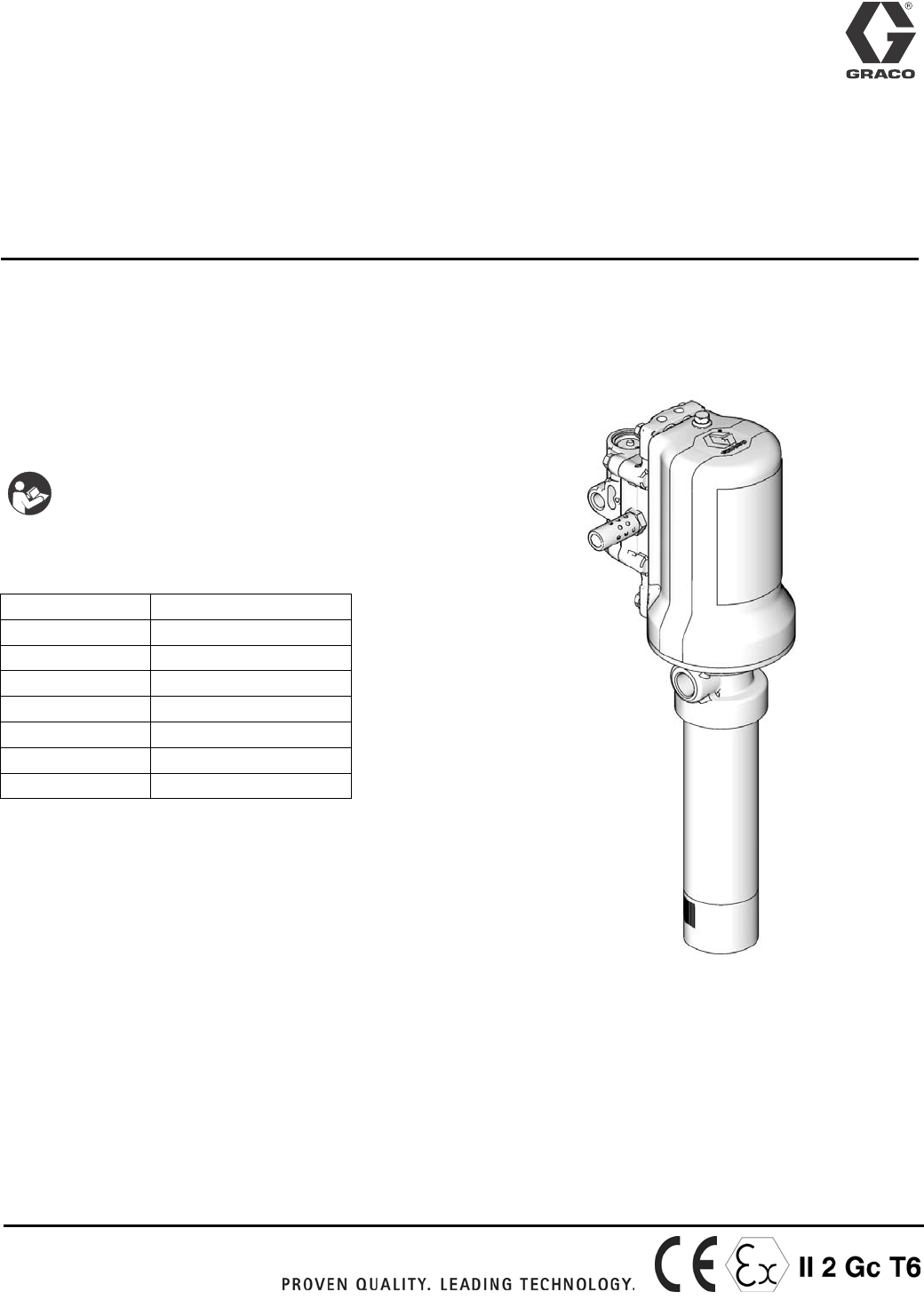
Instructions
LD Series Oil and Grease
Pump 3A1334E
For dispensing non-corrosive and non-abrasive lubricants, oil, grease, and automatic
transmission fluids in stationary or mobile installations. Use with compressed air only. For
professional use only. Not for use with windshield washer fluid.
List of models, including Maximum Fluid Pressure:
•Oil Pump Models: page 2
•Grease Pump Models: page 3
Related Translated Manuals
European Community Design Patent: 001278006-001;
001278006-002
Patents Pending
Important Safety Instructions
Read all warnings and instructions in this
manual. Save these instructions.
Manual Number Language
3A1339 Spanish
3A1345 French
3A1350 German
3A1360 Russian
3A1365 Chinese
3A1370 Japanese
3A1375 Korean
EN

Oil Pump Models
23A1334E
Oil Pump Models
All oil models include a 2” npt(m) bung adapter.
PN Description Max air pressure Max Fluid Pressure Air inlet Fluid
Inlet
Fluid
Outlet
3:1 PUMPS psi Mpa bar psi Mpa bar
24G576 Universal 150 1.03 10.3 750 5.17 51.7 1/4"-18
NPT
1"-11.5
NPT
1/2"-14
NPT
24G577 Universal 150 1.03 10.3 750 5.17 51.7 1/4"-19
BSPP
1-11
BSPP
1/2"-14
BSPP
24G578 Universal 150 1.03 10.3 750 5.17 51.7 1/4"-19
BSPT
1-11
BSPT
1/2”-14
BSPT
24G579* Multilength 150 1.03 10.3 750 5.17 51.7 1/4"-18
NPT
1"-11.5
NPT
1/2"-14
NPT
24G580* Multilength 150 1.03 10.3 750 5.17 51.7 1/4"-19
BSPP
1-11
BSPP
1/2"-14
BSPP
24G581* Multilength 150 1.03 10.3 750 5.17 51.7 1/4"-19
BSPT
1-11
BSPT
1/2”-14
BSPT
24G582* 200L (55gal) drum 150 1.03 10.3 750 5.17 51.7 1/4"-18
NPT
1"-11.5
NPT
1/2"-14
NPT
24G583* 200L (55gal) drum 150 1.03 10.3 750 5.17 51.7 1/4"-19
BSPP
1-11
BSPP
1/2"-14
BSPP
24G584* 200L (55gal) drum 150 1.03 10.3 750 5.17 51.7 1/4"-19
BSPT
1-11
BSPT
1/2”-14
BSPT
24G585* 1040 liter (275gal) tote 150 1.03 10.3 750 5.17 51.7 1/4"-18
NPT
1"-11.5
NPT
1/2"-14
NPT
24G586* 1040 liter (275gal) tote 150 1.03 10.3 750 5.17 51.7 1/4"-19
BSPP
1-11
BSPP
1/2"-14
BSPP
24G587* 1040 liter (275gal) tote 150 1.03 10.3 750 5.17 51.7 1/4"-19
BSPT
1-11
BSPT
1/2”-14
BSPT
5:1 PUMPS psi Mpa bar psi Mpa bar Air inlet Fluid
Inlet
Fluid
Outlet
24G588 Universal 150 1.03 10.3 750 5.17 51.7 1/4"-18
NPT
1"-11.5
NPT
1/2"-14
NPT
24G589 Universal 150 1.03 10.3 750 5.17 51.7 1/4"-19
BSPP
1-11
BSPP
1/2"-14
BSPP
24G590 Universal 150 1.03 10.3 750 5.17 51.7 1/4"-19
BSPT
1-11
BSPT
1/2”-14
BSPT
24G591* 5:1 Multilength 150 1.03 10.3 750 5.17 51.7 1/4"-18
NPT
1"-11.5
NPT
1/2"-14
NPT
24G592* 5:1 Multilength 150 1.03 10.3 750 5.17 51.7 1/4"-19
BSPP
1-11
BSPP
1/2"-14
BSPP
24G593* 5:1 Multilength 150 1.03 10.3 750 5.17 51.7 1/4"-19
BSPT
1-11
BSPT
1/2”-14
BSPT
24G594* 200L (55gal) drum 150 1.03 10.3 750 5.17 51.7 1/4"-18
NPT
1"-11.5
NPT
1/2"-14
NPT
24G595* 200L (55gal) drum 150 1.03 10.3 750 5.17 51.7 1/4"-19
BSPP
1-11
BSPP
1/2"-14
BSPP
24G596* 200L (55gal) drum 150 1.03 10.3 750 5.17 51.7 1/4"-19
BSPT
1-11
BSPT
1/2”-14
BSPT
24G597* 1040 liter (275gal) tote 150 1.03 10.3 750 5.17 51.7 1/4"-18
NPT
1"-11.5
NPT
1/2"-14
NPT
24G598* 1040 liter (275gal) tote 150 1.03 10.3 750 5.17 51.7 1/4"-19
BSPP
1-11
BSPP
1/2"-14
BSPP
24G599* 1040 liter (275gal) tote 150 1.03 10.3 750 5.17 51.7 1/4"-19
BSPT
1-11
BSPT
1/2”-14
BSPT
* Includes universal pump and down tube, packaged separately.

Grease Pump Models
3A1334E 3
Grease Pump Models
PN Description Max air pressure Max Fluid Pressure Air inlet Fluid
Inlet
Fluid
Outlet
50:1 PUMPS psi Mpa bar psi Mpa bar
24G600 16kg (35lb) 150 1.03 10.3 7500 51.7 517 1/4"-18
Npt
Priming
piston
1/4"-18
Npt
24G601 16kg (35lb) 150 1.03 10.3 7500 51.7 517 1/4"-19
BSPP
Priming
piston
1/4"-19
BSPP
24G602 16kg (35lb) 150 1.03 10.3 7500 51.7 517 1/4"-19
BSPT
Priming
piston
1/4"-19
BSPT
24G603 55kg (120lb) 150 1.03 10.3 7500 51.7 517 1/4"-18
Npt
Priming
piston
1/4"-18
Npt
24G604 55kg (120lb) 150 1.03 10.3 7500 51.7 517 1/4"-19
BSPP
Priming
piston
1/4"-19
BSPP
24G605 55kg (120lb) 150 1.03 10.3 7500 51.7 517 1/4"-19
BSPT
Priming
piston
1/4"-19
BSPT
24G606 180kg (400lb) 150 1.03 10.3 7500 51.7 517 1/4"-18
Npt
Priming
piston
1/4"-18
Npt
24G607 180kg (400lb) 150 1.03 10.3 7500 51.7 517 1/4"-19
BSPP
Priming
piston
1/4"-19
BSPP
24G608 180kg (400lb) 150 1.03 10.3 7500 51.7 517 1/4"-19
BSPT
Priming
piston
1/4"-19
BSPT
Warnings
43A1334E
Warnings
The following warnings are for the setup, use, grounding, maintenance, and repair of this equipment. The exclama-
tion point symbol alerts you to a general warning and the hazard symbols refer to procedure-specific risks. When
these symbols appear in the body of this manual, refer back to these Warnings. Product-specific hazard symbols and
warnings not covered in this section may appear throughout the body of this manual where applicable.
WARNING
SKIN INJECTION HAZARD
High-pressure fluid from dispense valve, hose leaks, or ruptured components will pierce skin. This may
look like just a cut, but it is a serious injury that can result in amputation. Get immediate surgical
treatment.
• Do not point dispense valve at anyone or at any part of the body.
• Do not put your hand over the end of the dispense nozzle.
• Do not stop or deflect leaks with your hand, body, glove, or rag.
• Follow Pressure Relief Procedure in this manual, when you stop spraying and before cleaning,
checking, or servicing equipment.
• Tighten all fluid connections before operating the equipment.
• Check hoses and couplings daily. Replace worn or damaged parts immediately.
FIRE AND EXPLOSION HAZARD
When flammable fluids are present in the work area, such as gasoline and windshield wiper fluid, be
aware that flammable fumes can ignite or explode. To help prevent fire and explosion:
• Use equipment only in well ventilated area.
• Eliminate all ignition sources, such as cigarettes and portable electric lamps.
• Keep work area free of debris, including rags and spilled or open containers of solvent and gasoline.
• Do not plug or unplug power cords or turn lights on or off when flammable fumes are present.
• Ground all equipment in the work area.
• Use only grounded hoses.
• If there is static sparking or you feel a shock, stop operation immediately. Do not use equipment until
you identify and correct the problem.
• Keep a working fire extinguisher in the work area.
Warnings
3A1334E 5
EQUIPMENT MISUSE HAZARD
Misuse can cause death or serious injury.
• Do not operate the unit when fatigued or under the influence of drugs or alcohol.
• Do not exceed the maximum working pressure or temperature rating of the lowest rated system
component. See Technical Data in all equipment manuals.
• Use fluids and solvents that are compatible with equipment wetted parts. See Technical Data in all
equipment manuals. Read fluid and solvent manufacturer’s warnings. For complete information about
your material, request MSDS forms from distributor or retailer.
• Check equipment daily. Repair or replace worn or damaged parts immediately with genuine
manufacturer’s replacement parts only.
• Do not alter or modify equipment.
• Use equipment only for its intended purpose. Call your distributor for information.
• Route hoses and cables away from traffic areas, sharp edges, moving parts, and hot surfaces.
• Do not kink or over bend hoses or use hoses to pull equipment.
• Keep children and animals away from work area.
• Comply with all applicable safety regulations.
PRESSURIZED ALUMINUM PARTS HAZARD
Use of fluids that are incompatible with aluminum in pressurized equipment can cause serious chemical
reaction and equipment rupture. Failure to follow this warning can result in death, serious injury, or
property damage.
• Do not use 1,1,1-trichloroethane, methylene chloride, other halogenated hydrocarbon solvents or
fluids containing such solvents.
• Many other fluids may contain chemicals that can react with aluminum. Contact your material supplier
for compatibility.
PERSONAL PROTECTIVE EQUIPMENT
You must wear appropriate protective equipment when operating, servicing, or when in the operating area
of the equipment to help protect you from serious injury, including eye injury, hearing loss, inhalation of
toxic fumes, and burns. This equipment includes but is not limited to:
• Protective eyewear, and hearing protection.
• Respirators, protective clothing, and gloves as recommended by the fluid and solvent manufacturer.
WARNING
Installation
63A1334E
Installation
NOTE: Reference letters and numbers in parentheses in the text refer to callouts in the figures and drawings.
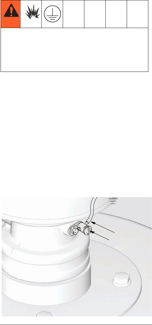
Grounding
Ground all equipment:
•Pump: Use a ground wire and clamp as shown in
FIG. 1.
a. Remove the ground screw (Z) and insert
through the eye of the ring terminal at end of
ground wire (Y).
b. Fasten the ground screw back onto the pump
and tighten securely.
NOTE: To order a ground wire and clamp, order Graco
Part No. 222011.
•Air and fluid hoses: Use only electrically conductive
hoses.
•Air compressor: Follow manufacturer’s recommen-
dations.
•Dispensing valve: Ground through connection to a
properly grounded fluid hose and pump.
•Object being dispensed to: Follow your local code.
•Solvent pails used when flushing: Follow your local
code. Use only metal pails, which are conductive,
placed on a grounded surface. Do not place the pail
on a nonconductive surface, such as paper or card-
board, which interrupts the grounding continuity.
•To maintain grounding continuity when flushing or
relieving pressure, hold a metal part of the dispens-
ing valve firmly to the side of a grounded metal pail,
then trigger the dispense valve.
To reduce the risk of static sparking, ground the pump
and all other components used or located in the
dispensing area. Check your local electrical code for
detailed instructions for your area and type of
equipment.
FIG. 1
Z
Y
ti16123
Installation
3A1334E 7
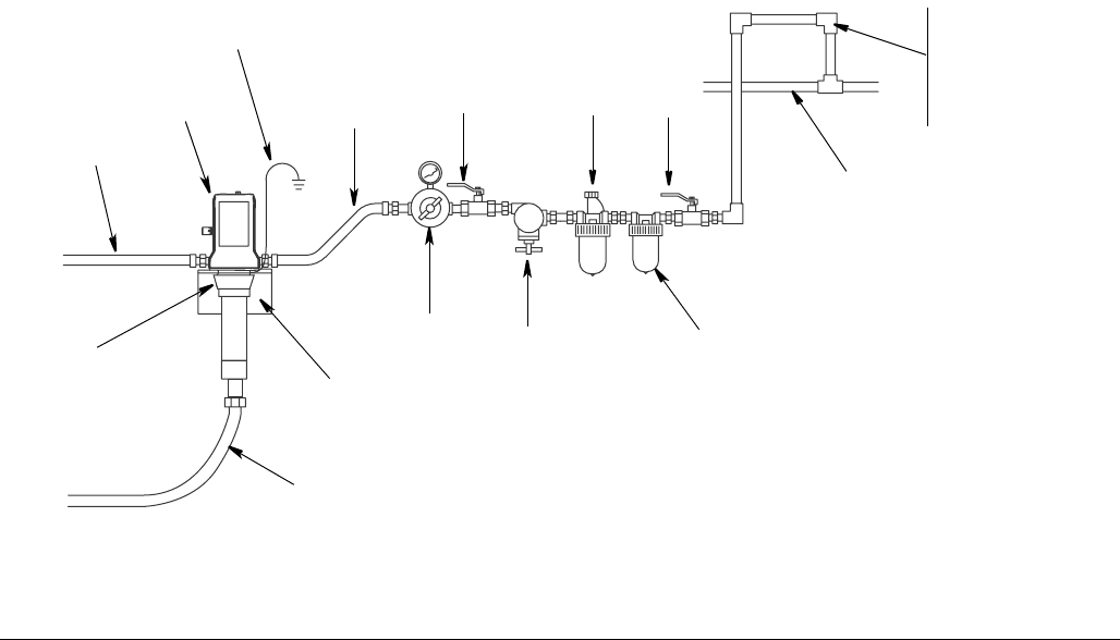
Typical Installation
The typical installation shown in FIG. 2 is only an installation guide. It is not an actual system design. Contact your
Graco Distributor for assistance in designing a system to suit your needs.
Stationary Mountings
Key (FIG. 2)
A Fluid outlet line (flexible connection required)
BPump
C Ground wire
D Pump runaway valve
E Air lubricator
F Bleed-type master air valve (required)
• NPT - Part No. 110223
• BSP - Part No. 125272
G Air regulator (self-relieving regulator required)
• NPT - Part No. 24H420
• BSP - Part No. 24H419
HAir filter
J Main air line
K Bung adapter - Part No. 24F918
L Fluid inlet line (flexible connection required)
M Air inlet line (flexible connection required)
N Wall mount bracket - Part No. 24F910
FIG. 2
A
B
D
C
E
F
ti16120
H
G
J
K
M
L
N
F
Recommended
air line
configuration
to reduce
moisture in pump
Installation
83A1334E
Installation Guidelines
Reference letters found in the following instructions,
refer to Typical Installation diagram provided on page 7.
• A ball valve must be installed upstream of the regu-
lator (G).
• The fluid outlet line (A), fluid inlet line (L) and air
inlet line (M) must be flexible (such as a hose).
NOTE: To prevent damage to the pump, remove sedi-
ment from the bottom of the container before installing a
pump on an existing container.
Stationary Mounting Layout
Plan the layout for easy operator access to the pump air
controls, sufficient room to change drums and a secure
platform.
Pump Mounting
1. Install bung adapter (K) into bung mount/bracket/or
drum cover.
2. Install pump (B) into bung adapter (K).
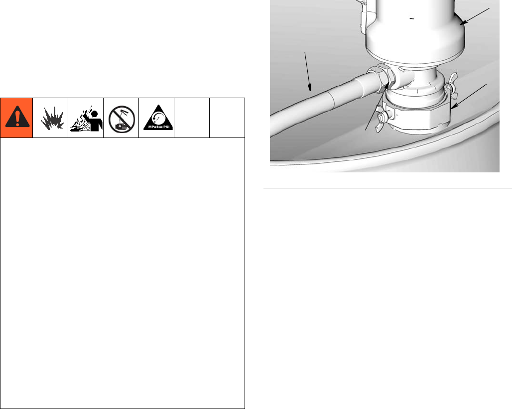
Installing Outlet Hose (FIG. 3)
1. Connect the swivel adapter (aa) to the pump fluid
outlet. Tighten securely and torque as recom-
mended below:
• For NPT models: 1 to 1-1/2 turns past hand
tight.
• For BSPT models: 1-1/2 to 2 turns past hand
tight.
2. Connect the fluid hose (A) to the swivel adapter
(aa).
3. Connect a suitable dispensing valve or extra hose to
the 6-ft hose.
The maximum working pressure of each pump in
your system may not be the same. To reduce the risk
of over-pressurizing any part of your system, which
may result in component rupture, fire or explosion
and cause serious bodily injury, be sure you know
the maximum working pressure rating of each pump
and its connected components.
•Never exceed the maximum working pressure of
the lowest rated component connected to a partic-
ular pump.
• Be sure you know the maximum working pressure
of each component.
• Do not exceed the maximum pump cycle rate.
• Regulate air pressure to prevent over pressuriza-
tion at fluid section of the pump.
• Regulate air pressure to the pump so that no fluid
line component or accessory is over pressurized.
FIG. 3
aa
A
K
B

Installation
3A1334E 9
Air Line and Accessories
NOTE: Install the air line accessories in the order shown
in the Typical Installation on page 7.
• Use thread sealant on all male threads except
swivel connections.
• Install a pump runaway valve (D) to shut off the air
to the pump if the pump accelerates beyond the
pre-adjusted setting. A pump that runs too fast can
be seriously damaged.
• Install the air regulator (G) to control pump speed
and pressure.
For NPT models order Graco Part No. 24H420 or for
BSP models order Graco Part No. 24H419.
• Install a bleed-type master air valve (F) upstream
from the pump air regulator (G) but within easy
reach of the pump.
For NPT models order Graco Part No. 110223 or for
BSP models order Graco Part No. 125272.
• On the main air supply line from the compressor,
install an air line filter (H) to remove harmful dirt and
contaminants from the compressor air supply.
Follow Plate - Grease Models Only
For grease models only a follow plate is required for
pumping fluid from the drum. See page 12 for follow
plate installation instructions.
NOTICE
Do not hang the air accessories directly on the air
inlet. Mount them on brackets. Always use a flexible
hose between all connections. The air inlet is not
strong enough to support accessories and may cause
one or more to break.
Operation
10 3A1334E
Operation
Thermal Induced Pressure
Relief (Oil pumps only)
Thermal Relief Theory of Operation
The pump operation is similar to most double acting
reciprocating pumps. The pump only comes to a com-
plete stop on the up stroke. The pump will stroke
through on the down stroke due to the inlet check relief
passage.
Excess pressure due to downstream thermal expansion
causes the air motor/pump to run backwards (down-
ward). Fluid pressure is relieved through the inlet check
relief passage as the pump piston moves downward. Air
pressure is simultaneously relieved through the air inlet
passage. The pump piston moves downward exposing
the pump cylinder relief passage at the bottom of the
stroke. Additional excess pressure is then relieved
through both the inlet check relief passage and the
pump cylinder relief passage.
Pressure is relieved at the pump through the pump inlet
relief passage. The pump will not change over on the
bottom of the stroke as a result of relieving excess pres-
sure due to the positioning of the pump cylinder groove
with respect to the air motor pilot valve.
NOTE:
• The air supply does not have to be turned off to
enable thermal relief activation.
• The Thermal Induced Pressure Relief design fea-
ture of the pump will cause the pump to dive on the
downstroke when a dispensing valve is closed.
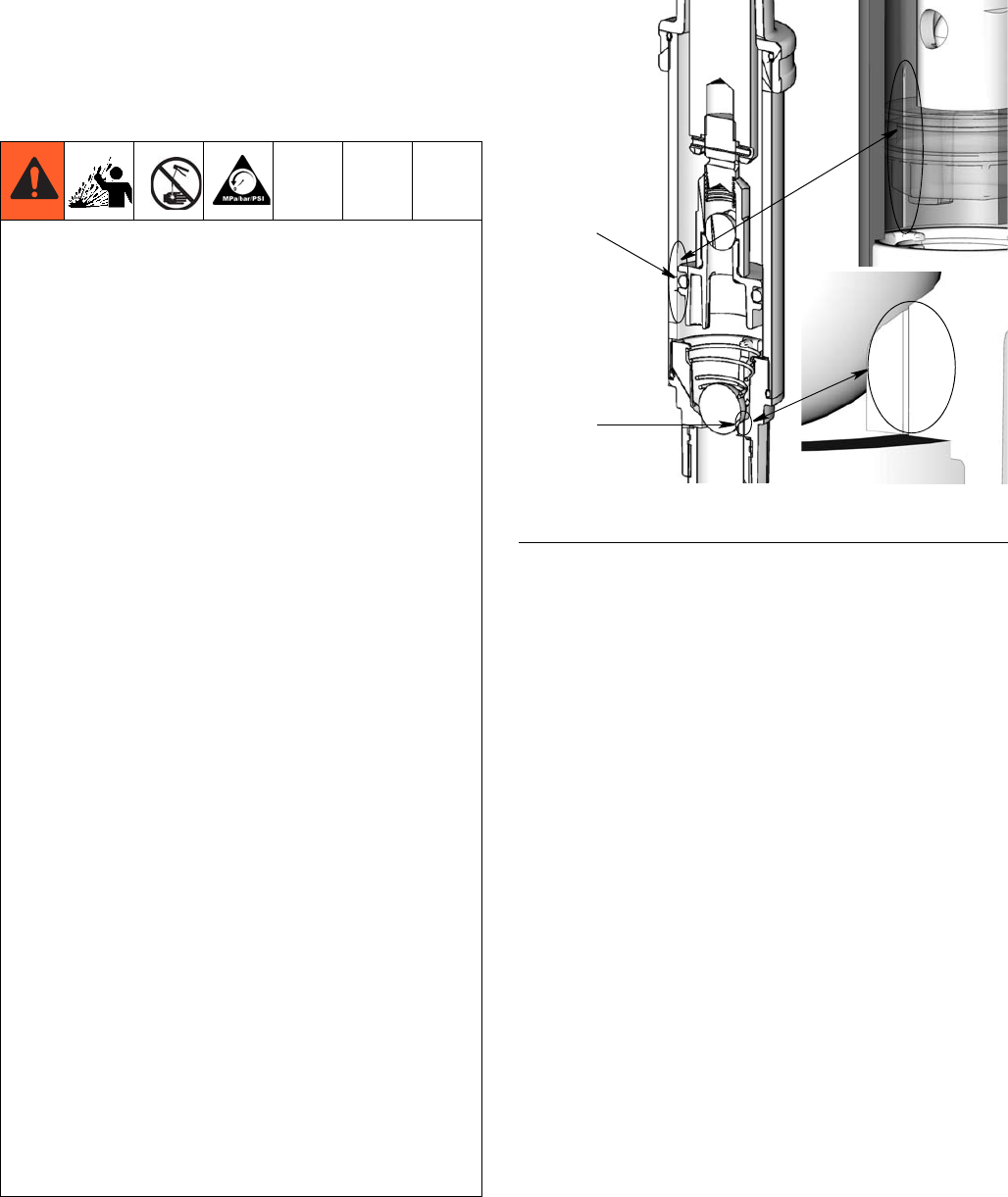
THERMAL EXPANSION HAZARD
Fluids subjected to heat in confined spaces, including
hoses, can create a rise in pressure due to the
thermal expansion. Over-pressurization can result in
equipment rupture and serious injury.
Oil pumps have a built-in, thermal induced, pressure
relief as shown in FIG. 4. To ensure system pressure
will automatically bleed excess thermal induced
system pressure through the pump and back to the
oil reservoir:
• Always use a relieving air pressure regulator to
allow the pump/motor to run backwards. The regu-
lator bleeds excess air pressure.
• There should not be any obstructions between air
inlet of pump and regulator.
• There should not be any obstructions between the
downstream plumbing and pump outlet such as
closed ball valves or check valves.
• There should not be any obstructions between the
pump inlet and fluid container such as closed ball
valves or check valves.
• Only use Graco designed suction tubes for in-drum
or in-tank applications.
• Only use Graco designed suction tubes with a
built-in relief device for wall mount applications.
• Always use an inlet screen to prevent debris from
plugging relief passages from entering the pump.
- Do not operate the pump with out an inlet screen.
• Periodically inspect the inlet screen for plugging.
Graco recommends inspecting the inlet screen
every time the container is changed out.
FIG. 4 a = Pump cylinder relief passage
b = Inlet check relief passage
a
b
Operation
3A1334E 11
Install only one pump per delivery system. Do not use
the pumps in a parallel pump installation.
Loss of pump prime can occur if all the following events
occur in sequence:
1. A thermal relief event occurs.
2. The air supply valve is closed.
3. A dispense valve located at an elevation higher than
the tank level, is open.
To prevent loss of prime, ensure the air supply valve is
turned on before attempting to dispense fluid.
Pressure Relief Procedure
1. Close the pump’s bleed-type master air valve.
2. Close the pump air regulator and disconnect the air
supply hose.
3. Open the dispensing valve and dispense fluid into a
waste bucket/container until pressure is fully
relieved.
If you suspect that the dispensing valve is clogged, or
that pressure has not been fully relieved after following
the steps above, very slowly loosen the dispensing
valve coupler or hose end coupling to relieve pressure
gradually, then loosen completely.
Start-up
Determining Output Pressure Using the Air
Regulator
To determine the fluid output pressure using the air reg-
ulator reading, multiply the ratio of the pump by the air
pressure shown on the regulator.
For example a 3:1 ratio oil pump:
3:1 ratio x 100 psi air = 300 psi fluid outlet
A 3:1 pump is capable of 5:1 on the downstroke and will
develop 5:1 pressures under normal operation.
A grease pump has a ratio of 50:1. However it is capable
of reaching a stall pressure equal to 60 times the air
input pressure. To calculate the fluid output pressure
using the air regulator reading, multiply the regulator
gauge by 60.
For example:
140 psi air x 60 = 8400 psi fluid output
0.97 MPa air x 60 = 58.2 MPa
99.7 bar x 60 = 582 bar
Regulate air to the pump so that no air line or fluid line
component or accessory is over pressurized.
Priming the pump
1. Close the air regulators and bleed-type master air
valves to all but one pump.
2. Open the master air valve from the compressor.
3. For the pump that is connected, trigger the dispens-
ing valve into a grounded metal waste container
making firm, metal-to-metal contact between the
container and the valve.
4. Slowly open the bleed-type master air valve and
open the pump air regulator just until the pump is
running. When the pump is primed and all air has
been pushed out of the lines, release the trigger.
5. If you have more than one pump, repeat this pro-
cess for each pump in your system.
NOTE: When the pump is primed and has sufficient
air supplied to it, it starts when the dispensing valve
is open and shuts off when closed.
The equipment stays pressurized until pressure is
manually relieved. To reduce the risk of serious injury
from pressurized fluid, fluid from the valve, or splash-
ing fluid, follow this procedure whenever you:
• are instructed to relieve pressure
• stop dispensing
• check, clean, or service any system equip-
ment
• install or clean dispensing devices.
Operation
12 3A1334E
Step 6 is for Oil Pumps Only:
6. The thermal relief feature of this oil pump can
increase the amount of time needed to fully prime
the pump when compared to pumps without a ther-
mal relief feature. To minimize this effect, prime the
pump before connecting it to an already primed dis-
tribution system.
7. Read and follow the instructions supplied with each
component in your system.
8. When shutting off the system and before checking
or servicing, relieve pressure following pressure
relief procedure, page 10.
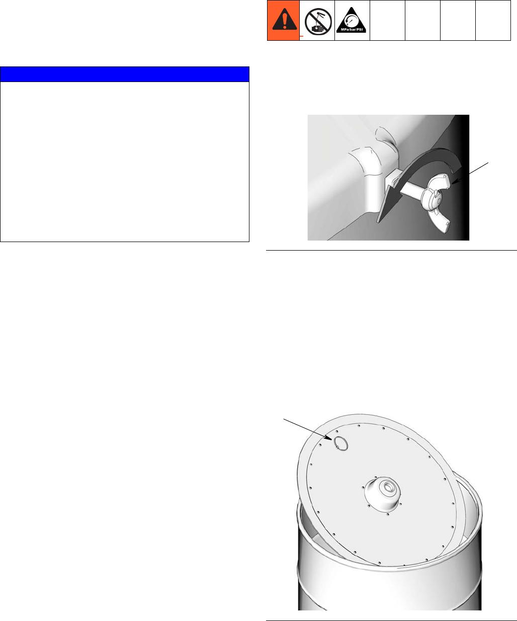
Changing Grease Drum and Installing
Follow Plate (grease models only)
1. Relieve pressure, page 10.
2. Remove drum cover by loosening thumb screws (a)
(FIG. 5).
3. Remove pump and cover from drum and place on a
clean paper, cardboard, or clean shop rags. DO
NOT PLACE ON SHOP FLOOR.
4. If this is an existing installation, reach into drum and
pull on follow plate ring (b) to remove follow plate
(FIG. 6). Place follow plate on a clean paper, card-
board or clean shop rags. DO NOT PLACE ON
SHOP FLOOR.
Remove drum and install new one.
NOTICE
Never allow the pump to run dry of the fluid being
pumped. A dry pump will quickly accelerate to a high
speed, possibly damaging itself. If your pump acceler-
ates quickly, or is running too fast, stop it immediately
and check the fluid supply. If the supply container is
empty and air has been pumped into the lines, prime
the pump and lines with fluid, or flush it and leave it
filled with a compatible solvent. Be sure to eliminate
all air from the fluid system.
NOTE: A pump runaway valve can be installed on the
air line to automatically shut off the pump if it starts to
run too fast. FIG. 5
FIG. 6
a
b
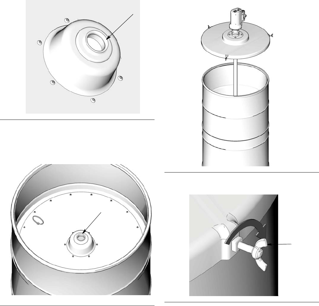
Operation
3A1334E 13
5. Examine follow plate to make sure rubber grommet
(c) is in place in center of the plate (FIG. 7).
6. Set follow plate on top of fresh grease (FIG. 8).
Remove air by pushing on the follow plate until the
grease level is flush with the opening in the middle
of the follow plate (d).
7. Insert pump drop tube through center of rubber
grommet in follow plate (FIG. 9).
Se
8. Tighten thumb screws (a) to secure cover to drum.
9. For the pump that is connected, trigger the dispens-
ing valve into a grounded metal waste container
making firm, metal-to-metal contact between the
container and the valve.
10. Slowly open the bleed-type master air valve and
open the pump air regulator just until the pump is
running. When the pump is primed and all air has
been pushed out of the lines, release the trigger.
FIG. 7
FIG. 8
c
d
FIG. 9
FIG. 10
a

Repair
14 3A1334E
Repair
Replacing Pilot Valves
Reference letters shown in the following instructions
refer to Typical Installation diagram, page 7. Part num-
bers refer to the Parts pages beginning on page 15.
1. Stop pump at the middle of its stroke.
2. Relieve pressure, page 11.
3. Disconnect the air line (M).
4. Use a 10 mm socket wrench to remove the old pilot
valve (20).
5. Lubricate o-rings and install the new pilot valve (20).
Torque to 95-105 in-lb (11-12 N.m).

Parts
3A1334E 15
Parts
3:1 Oil Pump Models: 24G576 - 24G587: 5:1 Oil Pump Models: 24G588 - 24G599
Ref Part No Description Qty
2 116343 SCREW, ground 1
3 SCREW 3
4 SCREW M6 x 22 mm 5
5✠O-RING, air piston 1
6✠O-RING 1
7✠O-RING 1
8✠O-RING, 1
9✠SEAL, u-cup 1
10 PIN, spring 1
11 ★BALL, steel 1
12 BALL, steel 1
13 ✓O-RING, (models 24G576 - 24G578) 1
✓O-RING (models 24G588 - 24G590) 1
14 ✓O-RING 1
15 ✓★ O-RING 1
16 SCREW 1
17 ✠O-RING 3
18 BOLT M8 X 25 1
19 WASHER, M8 (not shown) 1
20 ◆ ✖VALVE, pilot 2
21 PISTON, air, plastic 1
22 BEARING, delrin 1
23 15M182
❖ †✿ ◆SEAL, air valve, manifold (not shown) 1
24 15M213 MUFFLER, 3/8 1
112933 MUFFLER, quiet (optional) 1
25 ✠GASKET, cover, small 2
26 COVER, bottom, machining 1
27 CYLINDER air, machined 1
28 ★HOUSING, intake valve, machined 1
29 FLANGE, oil, machined 1
30 ROD, displacement 1
31 GUIDE, air 1
32 CYLINDER, fluid 1
33 PISTON, pump, 3:1, machining 1
34 HOLDER, ball 1
35 ★SPRING, compression 1
36 SPRING, compression 1
37 HOUSING, manifold, machined 1
38 ✿VALVE, air, small 1
39 ▲16F541 LABEL, identification, lD 3:1 1
40 ▲16G243◆LABEL, safety, warning, multiple 1
43 ✿SCREW, M6 x 25 mm 8
50 24F918 ADAPTER, bung, LD pump 1
51 16G121★STRAINER 1
52‡
16F878 TUBE, PVC, LD pump (models
24G579, 24G591) 1
16F948 TUBE, PVC, LD pump (models
24G580, 24G592) 1
16F949 TUBE, PVC, LD pump (models
24G581, 24G593) 1
53‡
16F886 TUBE, metal, LD pump (models
24G582, 24G594) 1
16F950 TUBE, metal, LD pump (models
24G583, 24G595) 1
16F951 TUBE, metal, LD pump (models
24G584, 24G596) 1
54‡
16F885 TUBE, metal, LD pump (models
24G585, 24G597) 1
16F962 TUBE, metal, LD pump (models
243G586, 24G598) 1
16F963 TUBE, metal, LD pump (models
24G587, 24G599) 1
55 ✠O-Ring (not shown) 1
▲Replacement Danger and Warning labels, tags, and
cards are available at no cost.
‡ Packaged separately with universal pump.
✠Included in kit 24H853
✓Included in kits 24K293 - 3:1; 24H855 - 5:1
★Included in kits 24H611 (npt), 24J430 (bspp) 24J431
(bspt)
❖Included in kit 24H798
†Included in kit 24H851
✿Included in kit 24H848 (npt), 24H849 (bspp), 24H850
(bspt)
◆Included in kit 24J757 (npt), 24J758 (bspp), 24J759
(bspt)
✖Included in kit 24H749
Ref Part No Description Qty
Parts
16 3A1334E
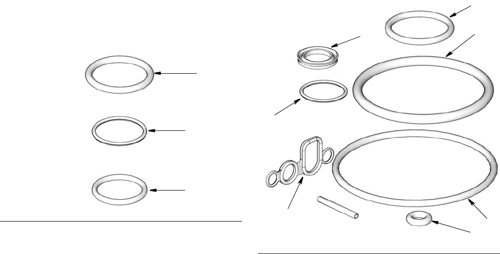
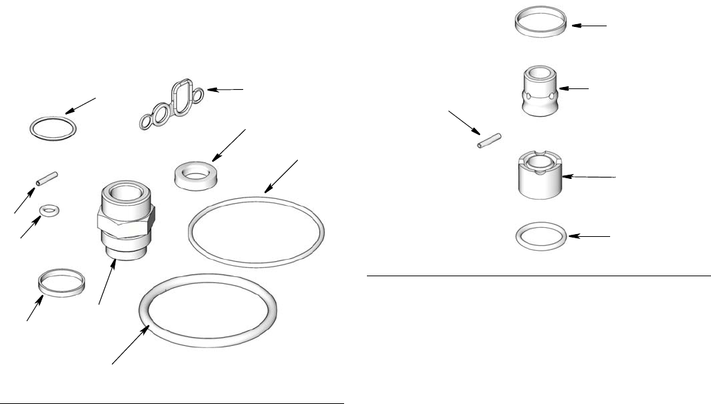
Related Oil Pump Kits
O-Ring Replacement Kit - 24K293 for 3:1
pumps; 24H855 for 5:1 pumps (FIG. 11)
NOTE: When replacing seals in the pump lower also
service the throat and piston seals. Order repair kit
24H853. Instructions related to this kit are included in
instruction manual 3A1494 (included with the kit).
Throat and Piston Seal Replacement Kit -
24H853 (FIG. 12)
NOTE: When servicing the throat and piston seals, it is
recommended to also replace seals in the pump lower.
Order repair kit: 24K293 for 3:1 pumps or 24H855 for
5:1 pumps. Instructions related to this kits are included
in instruction manual 3A1494 (included with the kit).
Kit No. Description Qty
24H611 KIT, repair, intake valve, npt,
includes 11, 15, 28, 35, 51 1
24J430 KIT, repair, intake valve, bspp,
includes 11, 15, 28, 35, 51 1
24J431 KIT, repair, intake valve, bspt,
includes 11, 15, 28, 35, 51 1
Ref. Description Qty.
13 O-RING 1
14 O-RING 1
15 O-RING 1
FIG. 11
13
14
15
Ref. Description Qty.
5 O-RING, air piston 1
6O-RING 1
7O-RING 1
8 O-RING, wiper 1
9 SEAL, u-cup 1
17 O-RING 3
25 GASKET, cover, small 2
55 O-RING (not shown) 1
FIG. 12
7
6
17
5
25
8
9
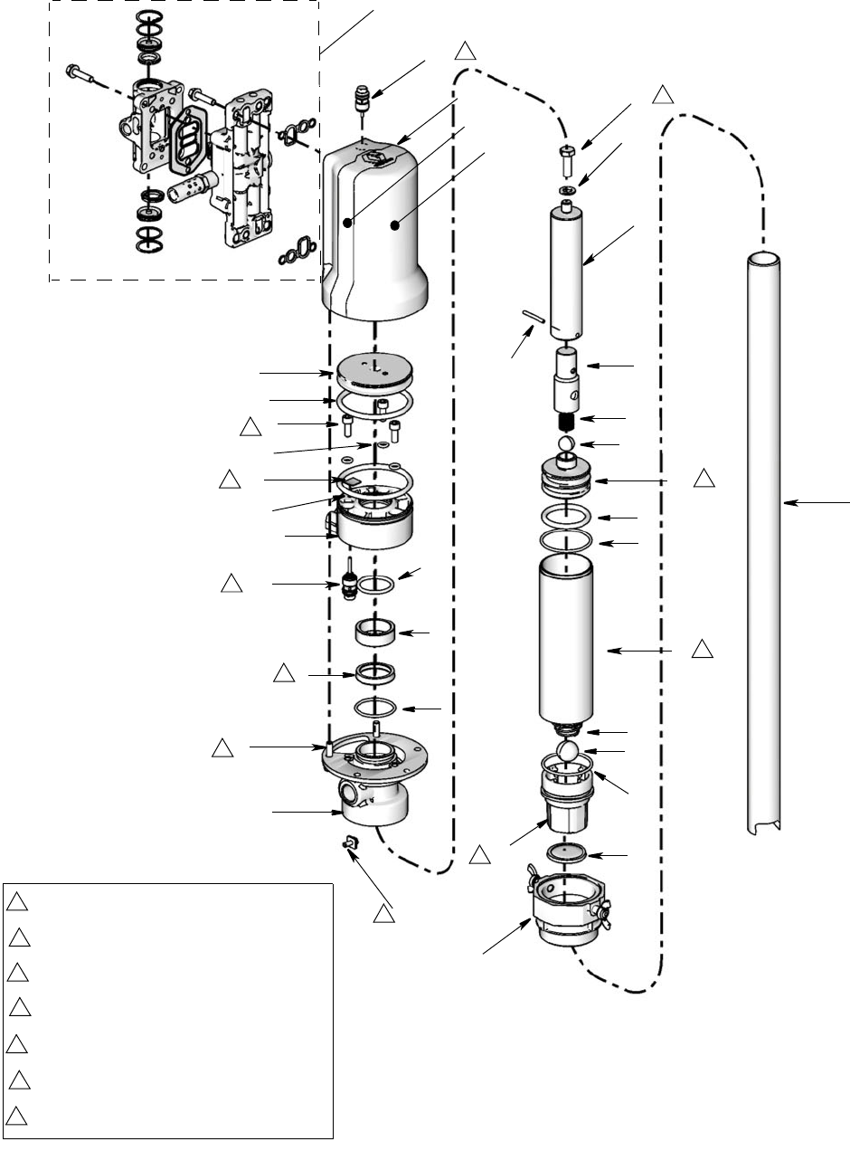
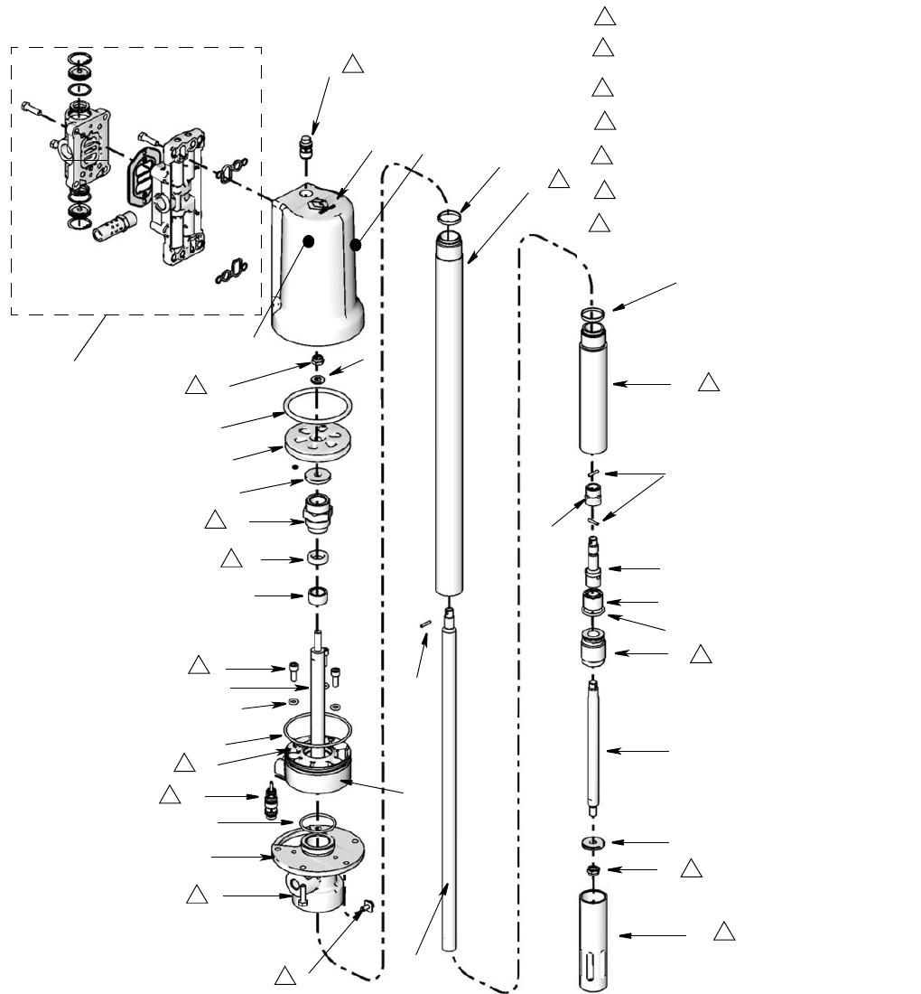
Parts
3A1334E 17
Kits
Page
2
39
40
27
26
21
29
4
32
10
12
30
34
33
35
11
28
52, 53
or 54,
Page 15
5
14
13
20
3
17
6
20
7
22
9
8
36
18
19
15
51
50
21
31
Torque to 60 - 70 in lbs (6.8 - 7.9 N•m)
3
Torque to 25 - 35 in lbs (2.8 - 3.9 N•m)
4
Torque to 110 - 120 in lbs (12.4 - 13.6 N•m)
5
Torque to 80 - 90 in lbs (9.0 - 10.2 N•m)
6
Torque to 20 - 25 ft lbs (27- 34 N•m)
2
Torque to 95-105 in lbs (10.7 - 11.9 N•m)
1
Lips face down
11
1
6
1
3
4
11
2
5
2
3
4

Parts
18 3A1334E
50:1 Grease Pump Models: 24G600 - 24G608
Ref Part No. Description Qty
2 116343 SCREW, ground 1
3 SCREW 3
4 SCREW, M6 X 22 mm 5
5+O-RING, air piston 1
6+O-RING (not shown) 1
7+O-RING 10
8+@ PIN, straight, slotted, 2.5x16 3
9 SCREW 1
10 @O-RING 1
11 +SEAL, u-cup 1
12 +O-RING 3
13 WASHER,M8 1
14 COVER, bottom, machining 1
15 PISTON, air, plastic 1
16 15M182
❖ † ✿◆ SEAL, air valve, manifold 1
17 15M213 MUFFLER, 3/8 1
112933 MUFFLER, quiet (optional) 1
18 +GASKET, cover, small 2
19 NUT, hex 2
20 ◆ ✖VALVE, pilot 2
21 CYLINDER, air, machined 1
22 FLANGE, bottom cover, grease, 1
23 ROD, piston, 50:1 1
24 @SEAL, piston 1
25 ROD, displacement, 50:1 1
26 CYLINDER, HP 50:1 1
27 24J380 KIT, cylinder, shovel 1
28 @SEAL, intake 1
29 RETAINER, seal, al 1
30 +@ GASKET 2
31 BEARING, throat 1
32 ROD, connection 1
33 GUIDE, air 1
34 ROD, priming 1
35 PISTON, shovel, 50:1 1
36 CYLINDER, spacer 1
37 +NUT, retainer 1
38 WASHER, 30 OD 1
39 HOUSING, manifold, machined 1
40 ✿◆ VALVE, air, small 1
41 ▲1GH013 LABEL, identification, LD 50:1 1
42 ▲16G243 LABEL, safety, warning, multiple 1
43 ✿SCREW, M6 x 25 mm 8
▲Replacement Danger and Warning labels, tags, and
cards are available at no cost.
+Included in kit 24H854
@Included in kits 24H856
★Included in kits 24H611 (npt), 24J430 (bspp) 24J431
(bspt)
❖Included in kit 24H798
†Included in kit 24H851
✿Included in kit 24H848 (npt), 24H849 (bspp), 24H850
(bspt)
◆Included in kit 24J757 (npt), 24J758 (bspp), 24J759
(bspt)
✖Included in kit 24H749
Ref Part No. Description Qty
Parts
3A1334E 19
Related Grease Pump Kits
Throat and Piston Seal Replacement Kit -
24H854 (FIG. 13)
Instructions related to this kit are included in instruction
manual 3A1495 (included with the kit).
O-Ring and Seal Replacement Kit - 24H856
(FIG. 14)
Instructions related to this kit are included in instruction
manual 3A1495 (included with the kit).
Ref. Description Qty.
5 O-RING, air piston 1
6O-RING 1
7O-RING 1
8 PIN, slotted, straight 3
11 SEAL, u-cup 1
12 O-RING 3
18 GASKET, cover, small 2
30 GASKET 1
37 NUT, retainer 1
FIG. 13
7
6
18
5
12
8
11
30 37
Ref. Description Qty.
8 PIN, slotted, straight 3
10 O-RING 1
24 SEAL, piston 1
28 SEAL, intake 1
30 GASKET 2
FIG. 14
28
10
24
30
8
Parts
20 3A1334E
41
42
21
Kits, page
15
3
2
8
8
34
27
4
14
20
5
13
38
37
11
31
30
25
6
12
33
36
32
26
24
23
28
10
29
35
19
7
22
19
30
21
1
8
8
8
7
8
7
10
3
20
1
9
3
9
11
Torque to 60 - 70 in lbs (6.8 - 7.9 N•m)
3
Torque to 30 - 40 in lbs (3.4 - 4.5 N•m)
9
Torque to 70 - 80 in lbs (7.9 - 9.0 N•m)
7
Torque to 45 - 55 ft lbs (61 - 75 N•m)
8
Torque to 95-105 in lbs (10.7 - 11.9 N•m)
1
Torque to 30 - 35 in lbs (3.4 - 4.0 N•m)
10
Lips face down
11
Parts
3A1334E 21
Oil or Grease Pump Air Valve
Repair and Replacement Kits
Instructions related to the following kits are included in
instruction manual 3A1496 (included with the kit).
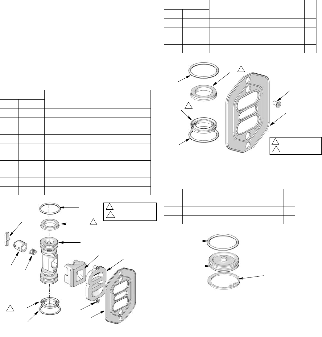
Replace Seals or Rebuild Air Valve Kits
Air Valve Repair Kit - 24H798, Air Valve Seal Kit -
24H851 and Air Valve End Cap - 24H852.
Air Valve Repair Kit - 24H798
Air Valve Seal Kit - 24H851
Air Valve End Cap Kit - 24H852
Ref. Description Qty.
Oil Grease
23 16 SEAL, air valve, manifold 1
381 381 O-RING, 018 buna 2
382 382 SEAL, u-cup, bevel lip 2
383 383 SCREW, M3, thread forming 2
386 386 PISTON, air valve 1
387 387 ROLLER, assembly, detent 1
388 388 PLATE, air valve 1
389 389 SPRING, detent, small 1
390 390 CUP, air valve, small 1
391 391 CAM, detent, small 1
FIG. 15
383
23/16
391
387 389
381
382
386
382
381
390 388
1
2
1
Lips face down
2
Lips face up
Ref. Description Qty.
Oil Grease
23 16 SEAL, air valve, manifold 1
381 381 O-RING, 018 buna 2
382 382 SEAL, u-cup, bevel lip 2
383 383 SCREW, M3, thread forming 2
FIG. 16
Ref. Description Qty.
381 O-RING, 018 buna 2
384 PLUG, air valve 2
385 RING, snap 2
FIG. 17
23/16
383
382
382
381
381 1Lips face down
Lips face up
2
2
1
385
384
381
Parts
22 3A1334E
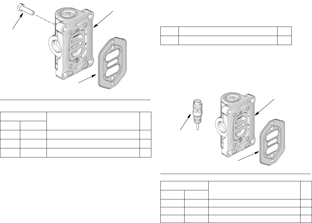
Air Valve Replacement Kit - 24H848 (npt),
24H849 (bspp), 24H850 (bspt) (FIG. 18) Pilot Valve Replacement Kit - 24H749
This kit only includes the pilot valves (20). If you
also are repairing/replacing the air valve (38/40) and
air valve seal (23/16) order the Air Motor Service Kit -
24J757 (npt), 24J758 (bspp) or 24J759 (bspt).
Air Motor Service Kit - 24J757 (npt), 24J758
(bspp), 24J759 (bspt) (FIG. 19)
I
FIG. 18
Ref. Description Qty.
Oil Grease
23 16 SEAL, air valve 1
38 40 VALVE, air, small 1
43 43 SCREW, M6 x 25 4
43
38/40
23/16
Ref. Description Qty.
20 VALVE, pilot 2
FIG. 19
Ref. Description Qty.
Oil Grease
20 20 VALVE, pilot 2
23 16 SEAL, air valve 1
40 40 VALVE, air, small 1
20
38/40
23/16
Troubleshooting
3A1334E 23
Troubleshooting
NOTE: Check all other possible problems and solutions
before disassembling the pump. Before you troubleshoot
problems using the table below, relieve the pressure
and disconnect the pump fluid line. If the pump starts
when the air is turned on again, the fluid line, dispensing
valve, etc. clogged.
Oil Models
Problem Cause Solution
Pump runs but no fluid output
Pump is not fully primed
Crack a fitting at the outlet of the
pump to allow a slow leak to purge
any air in the pump. Repeat start up
procedure, page 11.
Oil leakage Check connection and tighten.
The piston valve is not seating prop-
erly or the piston o-ring is damaged Check and replace parts as needed.
Exhausted fluid supply Refill and reprime.
The pump inlet filter is blocked Clear the filter
The suction tube (hose) has an air
leak
Check the connection and tighten as
needed.
Pump fails to operate or stops
Damaged pilot valve
Service pilot valve.
Lower air pressure to prevent reoc-
currence.
Damaged main air valve
Replace air valve.
Lower air pressure to prevent reoc-
cur an ce.
Inadequate air supply pressure or
restricted air lines. Increase air supply; clear.
Closed or clogged dispensing valve Open valve if closed. Clear clog if
necessary.
Clogged fluid lines, hose valves, etc. Clear clogs.
Damaged air motor Service air motor.
Erratic or accelerated operation
Exhausted fluid supply Refill and reprime.
Damaged valve gasket
Replace valve gasket.
Lower air pressure to prevent reoc-
currence.

Troubleshooting
24 3A1334E
Intermittent air leakage coming from
behind the air manifold. Pump con-
tinues to function normally.
Gasket is leaking
Replace gasket.
Lower air pressure to prevent reoc-
currence.
Thermal relief inlet check relief pas-
sage in inlet housing is plugged
Clear obstruction.
Replace inlet filter.
Continuous air exhaust
Worn or damaged piston o-ring or
valve cup. Service air motor / valve
Damaged valve gasket
Replace valve gasket.
Lower air pressure to prevent reoc-
currence.
Pump operates but output is low
Held open or worn intake valve Clear; service.
Held open or worn pump piston
packings Clear; service.
The muffler is partially blocked Clear muffler.
The inlet filter is partially blocked Clear the filter.
Inadequate air supply pressure or
restricted air lines
Increase air supply; clear restric-
tions.
Partially closed or clogged pilot
valves
Open valves. Clear clog as neces-
sary.
Partially clogged fluid line, hose,
valves, etc. Clear clog as necessary.
Oil leakage through air exhausts Throat seal is damaged Replace throat seal (u-cup).
Problem Cause Solution

Troubleshooting
3A1334E 25
Grease Models
Pump fails to operate Inadequate air supply pressure or
restricted air lines
Increase air supply and/or clear
restriction.
Closed or clogged pump valves Open and/or clean.
Clogged fluid line, hose, valve, or
other accessory
Relieve pressure.
Clear obstruction.
Damaged air motor Assess damage, and service air
motor.
Exhausted fluid supply Refill and reprime or flush.
Continuous air exhaust Worn or damaged piston o-ring or
valve cup
Assess wear or damage, and service
air motor.
Erratic pump operation Exhausted fluid supply Refill and reprime or flush.
Worn pump seals Replace.
Damaged shovel tube Replace.
Damaged check seat Replace pump piston or shovel rod
(or other damaged part).
Errataic or accelerated pump speed Exhausted fluid supply Refill and reprime of flush.
Fluid too heavy for pump priming Use inductor or follow plate.
Damaged valve gasket
Replace valve gasket.
Lower air pressure to prevent reoc-
currence.
Pump operates but output is low
Worn piston seal Replace.
Damaged upper check seat Replace pump piston.
Worn fluid intake seal Replace.
Damaged lower check seat Replace shovel rod.
Inadequate air supply pressure or
restricted air lines
Increase air supply and/or clear
restriction.
Partially closed or clogged pump
valves
Open and/or clean.
Air pockets in the grease inlet Eliminate the air pockets.
Partially clogged fluid line, hose,
valve, or other accessory
Relieve pressure.
Clear obstruction.
Worn seals Replace.
Grease leaking from muffler Worn throat seal Replace.

Technical Data
26 3A1334E
Technical Data
3:1 or 5:1 Oil Models
† Calculated at a distance of 1 meter from measurements taken per ISO 9614-2 @ 100 psi air pressure (6.89 bar,
0.68 MPa) and 20 cycles per minutes.
‡ Measured per ISO 9614-2 at 100 psi air pressure (6.89 bar, 0.68 MPa) and 20 cycles per minute.
* Muffler 112933 can be ordered separately for reduced sound levels.
Maximum fluid working pressure 750 psi (51.7 bar, 5.17 MPa)
Fluid pressure ratio 3:1 or 5:1
Suction lift (feet of oil) 10
Air operation range 20 to 150 psi (1.37 to 10.3 bar; 0.137 to 1.03 MPa)
Recommended air pressure for optimum
pump life
<125 psi (8.6 bar, 0.86 MPa)
Air consumption (at 100 psi) See Performance Curves, page 29
Cycles per gallon/(liter) 3:1 - 29 cycles per gallon (7 cycles per liter); 5:1 - 37 cycles per gallon)
(10 cycles per liter)
Maximum recommended pump speed 3:1 - 120 cycles per minute; 5:1 - 180 cycles per minutes
Recommended speed for optimum pump
life
75 cycles per minute and lower
3:1 - 2.6 gallons per minute (9.8 liters per minute); 5:1 - 2 gallons per
minute (7.6 liters per minute)
Wetted parts zinc plated carbon, steel, aluminum, nitrile, polyurethane, nickel plated
aluminum
Sound pressure level†* 72.9 dB(a)
Sound power level‡* 82.0 dB(a)
Performance curve See charts page 28
Approximate weight 3:1 - 7 pounds (3.2 kg); 5:1 - 7.7 pounds (3.5 kg)
Dimensions See page 30
Technical Data
3A1334E 27
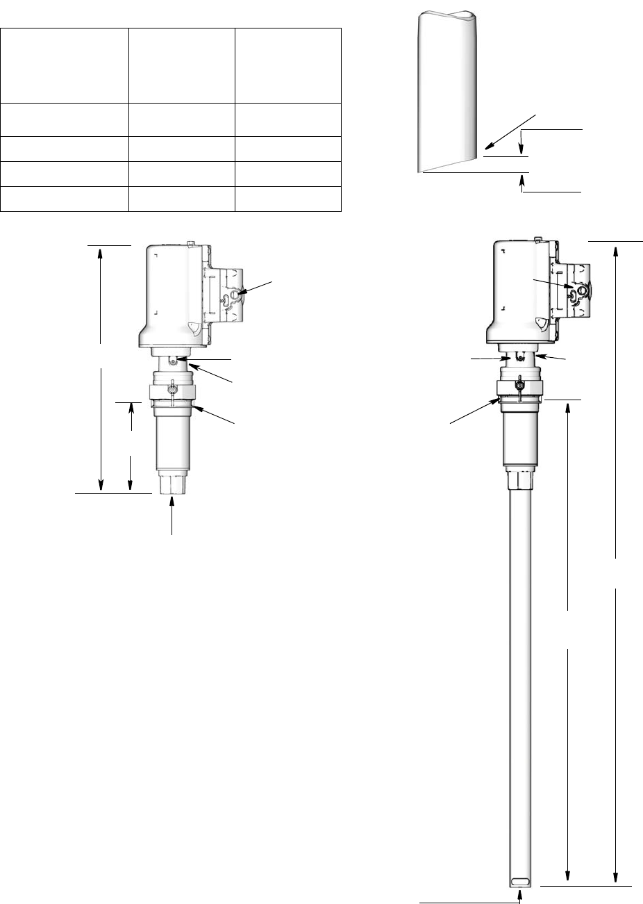
Dimensions
Model L
inches (mm)
O
(Overall Length)
inches (mm)
Universal Pump
Only 6.9 (175) 16 (406)
Multi* 42.4 (1076) 51.5 (1307)
Drum 35.7 (907) 44.8 (1138)
Tote 42.8 (1087) 51.9 (1318)
*Multi down tube is angle
cut to the desired length
as required
3/8” (10 mm)
minimum
L
L
Universal Pump Multi/Drum/Tote
O
O
a
a = 1/4 inch air inlet
b = 1 inch fluid inlet
c = 2 inch npt bung adapter
d = ground screw
a
dd
cc
b
b
e
e
e = 1/2 inch fluid outlet - opposite of d
Technical Data
28 3A1334E
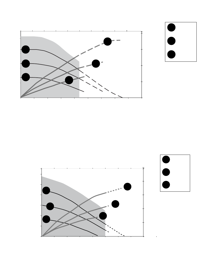
Performance Curve
3:1 Oil Models
5:1 Oil Models
0
10
(.3)
20
(.6)
30
(.8)
40
(1.1)
0
100
(6.9)
200
(13.8)
300
(20.7)
400
(27.6)
0 1
(3.8)
2
(7.6)
3
(11.4)
4
(15.1)
5
(18.9)
6
(22.7)
7
(26.5)
8
(30.3)
9
(34.1)
58 116 174 232
$LU)ORZVFIP
PPLQ
)OXLG)ORZJSP
OSP
&\FOHVSHUPLQXWH
$
%
&
SVL
EDU
SVL
EDU
SVL
EDU
,QOHW$LU3UHVVXUHV
3:1 Performance Curve
Tested with ISO 46 Hyd Oil
5HFRPPHQGHG2SHUDWLQJ5DQJH
)OXLG3UHVXUHSVL
EDU
$
%
&
$
%
&
0
10
(.3)
20
(.6)
30
(.8)
40
(1.1)
0
100
(6.9)
200
(13.8)
300
(20.7)
400
(27.6)
500
(34.5)
600
(41.4)
0 1
(3.84)
2
(7.6)
3
(11.4)
4
(15.1)
5
(18.9)
6
(26.5)
74 148 222
7
(26.5)
$LU)ORZVFIP
PPLQ
)OXLG)ORZJSP
OSP
5:1 Performance Curve
Tested with ISO 46 Hyd Oil
5HFRPPHQGHG2SHUDWLQJ5DQJH
)OXLG3UHVXUHSVL
EDU
&\FOHVSHUPLQXWH $
%
&
SVL
EDU
SVL
EDU
SVL
EDU
,QOHW$LU3UHVVXUHV
$
%
&
$
%
&
Technical Data
3A1334E 29
50:1 Grease Models
† Calculated at a distance of 1 meter from measurements taken per ISO 9614-2 @ 100 psi air pressure (6.89 bar,
0.68 MPa) and 20 cycles per minutes.
‡ Measured per ISO 9614-2 at 100 psi air pressure (6.89 bar, 0.68 MPa) and 20 cycles per minute.
* Muffler 112933 can be ordered separately for reduced sound levels.
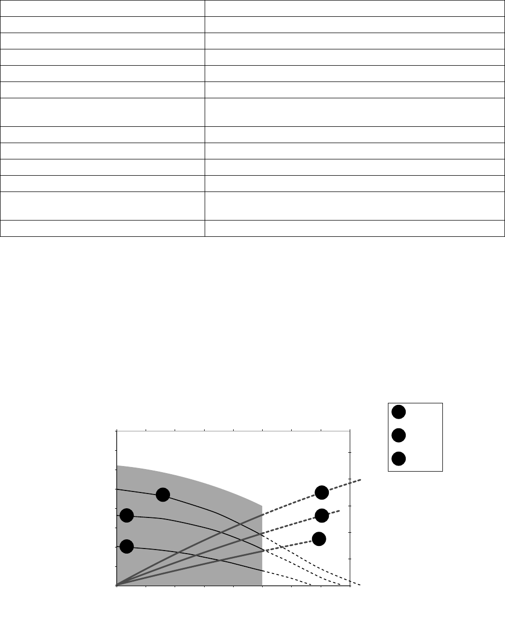
Performance Curve
Grease Models
Maximum working pressure 7500 psi (517 bar, 51.7 MPa)
Fluid pressure ratio 50:1
Air operation range 20 to 150 psi (1.37 to 10.3 bar; 0.137 to 1.03 MPa)
Air consumption (at 100 psi) See Performance Curve, page 30
Pump cycles per pound (cycles per kg) 47 cycle per pound (103 cycle per kg)
Maximum recommended pump speed 120 cycles per minute
Recommended speed for optimum pump life 60 cycles per minute or lower flow rate; 1.3 pounds per minute
(0.6 kg per minute)
Wetted parts steel, brass, nitrile rubber, polyurethane, UHMWPE, acetal
Sound pressure level†* 72.9 dB(a)
Sound power level‡* 82.0 dB(a)
Performance curve See chart page 30
Approximate weight 35 pound drum - 11.2 pounds (5.1 kg); 120 pound drum - 15.0
pounds (6.8 kg); 400 pound drum - 170.0 pounds (7.7 kg)
Dimensions See illustration below
0
10
(.3)
20
(.6)
30
(.8)
40
(1.1)
50
(1.4)
0
1000
(68.9)
2000
(137.9)
3000
(206.8)
4000
(275.8)
5000
(344.7)
6000
(413.7)
7000
(482.6)
8000
(551.6)
0.00 0.50
(.23)
1.00
(.45)
1.50
(.68)
2.00
(.91)
2.50
(1.13)
3.00
(1.36)
47 94 141
3.50
(1.59)
4.00
(1.81)
$LU)ORZVFIP
PPLQ
)OXLG)ORZOEVP
NJP
50:1 Performance Curve
Tested with ISO 46 Hyd Oil
5HFRPPHQGHG2SHUDWLQJ5DQJH
)OXLG3UHVXUHSVL
EDU
&\FOHVSHUPLQXWH
$
%
&
SVL
EDU
SVL
EDU
SVL
EDU
,QOHW$LU3UHVVXUHV
$
%
&
$
%
&
Technical Data
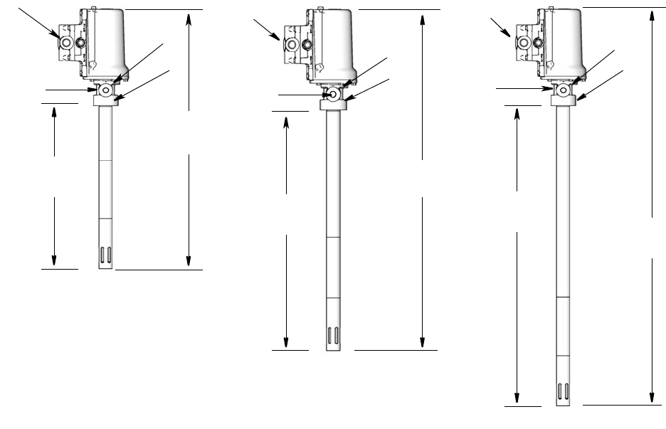
30 3A1334E
Dimensions
600 mm
945 mm
1145 mm
23.6 in.
37.2 in.
45.0 in.
400 pound drum
120 pound drum
35 pound drum
14.5 in.
370 mm
28.1 in.
715 mm
36.0 in.
915 mm
a = 1/4 inch air inlet
b = 1/4 inch fluid outlet
c = 2 inch npt mounting configuration
d = ground screw
a
d
c
b
d
a
bcb
a
d
c

Notes
3A1334E 31
Notes
All written and visual data contained in this document reflects the latest product information available at the time of publication.
Graco reserves the right to make changes at any time without notice.
Original instructions. This manual contains English. MM 3A1334
Graco Headquarters: Minneapolis
International Offices: Belgium, China, Japan, Korea
GRACO INC. P.O. BOX 1441 MINNEAPOLIS, MN 55440-1441
Copyright 2011, Graco Inc. is registered to ISO 9001
www.graco.com
4/2011, revised9/2011
Graco Standard Warranty
Graco warrants all equipment referenced in this document which is manufactured by Graco and bearing its name to be free from defects in
material and workmanship on the date of sale to the original purchaser for use. With the exception of any special, extended, or limited warranty
published by Graco, Graco will, for a period of twelve months from the date of sale, repair or replace any part of the equipment determined by
Graco to be defective. This warranty applies only when the equipment is installed, operated and maintained in accordance with Graco’s written
recommendations.
This warranty does not cover, and Graco shall not be liable for general wear and tear, or any malfunction, damage or wear caused by faulty
installation, misapplication, abrasion, corrosion, inadequate or improper maintenance, negligence, accident, tampering, or substitution of
non-Graco component parts. Nor shall Graco be liable for malfunction, damage or wear caused by the incompatibility of Graco equipment with
structures, accessories, equipment or materials not supplied by Graco, or the improper design, manufacture, installation, operation or
maintenance of structures, accessories, equipment or materials not supplied by Graco.
This warranty is conditioned upon the prepaid return of the equipment claimed to be defective to an authorized Graco distributor for verification of
the claimed defect. If the claimed defect is verified, Graco will repair or replace free of charge any defective parts. The equipment will be returned
to the original purchaser transportation prepaid. If inspection of the equipment does not disclose any defect in material or workmanship, repairs will
be made at a reasonable charge, which charges may include the costs of parts, labor, and transportation.
THIS WARRANTY IS EXCLUSIVE, AND IS IN LIEU OF ANY OTHER WARRANTIES, EXPRESS OR IMPLIED, INCLUDING BUT NOT LIMITED
TO WARRANTY OF MERCHANTABILITY OR WARRANTY OF FITNESS FOR A PARTICULAR PURPOSE.
Graco’s sole obligation and buyer’s sole remedy for any breach of warranty shall be as set forth above. The buyer agrees that no other remedy
(including, but not limited to, incidental or consequential damages for lost profits, lost sales, injury to person or property, or any other incidental or
consequential loss) shall be available. Any action for breach of warranty must be brought within two (2) years of the date of sale.
GRACO MAKES NO WARRANTY, AND DISCLAIMS ALL IMPLIED WARRANTIES OF MERCHANTABILITY AND FITNESS FOR A
PARTICULAR PURPOSE, IN CONNECTION WITH ACCESSORIES, EQUIPMENT, MATERIALS OR COMPONENTS SOLD BUT NOT
MANUFACTURED BY GRACO. These items sold, but not manufactured by Graco (such as electric motors, switches, hose, etc.), are subject to
the warranty, if any, of their manufacturer. Graco will provide purchaser with reasonable assistance in making any claim for breach of these
warranties.
In no event will Graco be liable for indirect, incidental, special or consequential damages resulting from Graco supplying equipment hereunder, or
the furnishing, performance, or use of any products or other goods sold hereto, whether due to a breach of contract, breach of warranty, the
negligence of Graco, or otherwise.
FOR GRACO CANADA CUSTOMERS
The Parties acknowledge that they have required that the present document, as well as all documents, notices and legal proceedings entered into,
given or instituted pursuant hereto or relating directly or indirectly hereto, be drawn up in English. Les parties reconnaissent avoir convenu que la
rédaction du présente document sera en Anglais, ainsi que tous documents, avis et procédures judiciaires exécutés, donnés ou intentés, à la suite
de ou en rapport, directement ou indirectement, avec les procédures concernées.
Graco Information
For the latest information about Graco products, visit www.graco.com.
TO PLACE AN ORDER, contact your Graco distributor or call to identify the nearest distributor.
Phone: 612-623-6928 or Toll Free: 1-800-533-9655, Fax: 612-378-3590
