Graco 3A2894F Exactablend Agp Advanced Glazing Proportioner Users Manual Proportioner, Setup Operation, English
2015-04-02
: Graco Graco-3A2894F-Exactablend-Agp-Advanced-Glazing-Proportioner-Users-Manual-686125 graco-3a2894f-exactablend-agp-advanced-glazing-proportioner-users-manual-686125 graco pdf
Open the PDF directly: View PDF ![]() .
.
Page Count: 78
- Contents
- Related Manuals
- Models
- Warnings
- Important Isocyanate (ISO) Information
- Component Identification
- Installation
- Setup
- Startup
- Base Purge
- Pressure Relief Procedure
- Shutdown
- Calibration Check
- Maintenance
- Troubleshooting
- Accessories and Kits
- Appendix A - DM Icons Overview
- Appendix B - DM Setup Screens Overview
- Appendix C - DM Run Screens Overview
- Appendix D - DM Error Codes
- Schematics
- Dimensions
- Technical Data
- Graco Standard Warranty
- Graco Information
3A2894F
EN
Setup-Operation
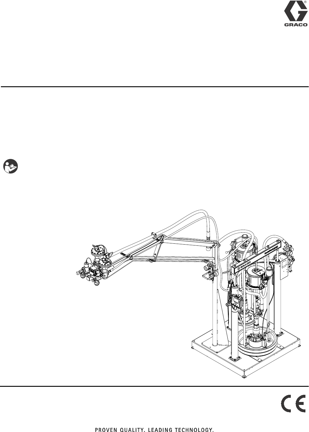
ExactaBlend™ AGP
Advanced Glazing
Proportioner
For dispensing two component silicone, polysulfide, and urethane materials.
For professional use only.
Not approved for use in explosive atmospheres or hazardous locations.
See page 4 for model information, including maximum working pressure and approvals.
Important Safety Instructions
Read all warnings and instructions in this
manual. Save these instructions.
S100 Shown
Contents
23A2894F
Contents
Contents . . . . . . . . . . . . . . . . . . . . . . . . . . . . . . . . . . 2
Related Manuals . . . . . . . . . . . . . . . . . . . . . . . . . . . 3
Models . . . . . . . . . . . . . . . . . . . . . . . . . . . . . . . . . . . 4
Base Machines . . . . . . . . . . . . . . . . . . . . . . . . . . 4
Hose Kits . . . . . . . . . . . . . . . . . . . . . . . . . . . . . . . 5
Dispense Valves . . . . . . . . . . . . . . . . . . . . . . . . . 5
Warnings . . . . . . . . . . . . . . . . . . . . . . . . . . . . . . . . . 6
Important Isocyanate (ISO) Information . . . . . . . . 8
Isocyanate Conditions . . . . . . . . . . . . . . . . . . . . 8
Material Self-ignition . . . . . . . . . . . . . . . . . . . . . . 8
Keep Components A and B Separate . . . . . . . . . 8
Moisture Sensitivity of Isocyanates . . . . . . . . . . . 9
Changing Materials . . . . . . . . . . . . . . . . . . . . . . . 9
Component Identification . . . . . . . . . . . . . . . . . . . 10
S100 Models . . . . . . . . . . . . . . . . . . . . . . . . . . . 10
U100 Models . . . . . . . . . . . . . . . . . . . . . . . . . . . 11
P100 Models . . . . . . . . . . . . . . . . . . . . . . . . . . . 12
Display Module (DM) . . . . . . . . . . . . . . . . . . . . . 14
User Interface . . . . . . . . . . . . . . . . . . . . . . . . . . 14
Electrical Enclosure . . . . . . . . . . . . . . . . . . . . . 17
Integrated Air Controls . . . . . . . . . . . . . . . . . . . 18
Fluid Control Module (FCM) . . . . . . . . . . . . . . . 20
Installation . . . . . . . . . . . . . . . . . . . . . . . . . . . . . . . 22
Grounding . . . . . . . . . . . . . . . . . . . . . . . . . . . . . 32
Setup . . . . . . . . . . . . . . . . . . . . . . . . . . . . . . . . . . . . 33
Startup . . . . . . . . . . . . . . . . . . . . . . . . . . . . . . . . . . 42
Base Purge . . . . . . . . . . . . . . . . . . . . . . . . . . . . . . . 44
Pressure Relief Procedure . . . . . . . . . . . . . . . . . . 46
Shutdown . . . . . . . . . . . . . . . . . . . . . . . . . . . . . . . . 48
Calibration Check . . . . . . . . . . . . . . . . . . . . . . . . . 49
Maintenance . . . . . . . . . . . . . . . . . . . . . . . . . . . . . . 52
Adjust Packing Nuts . . . . . . . . . . . . . . . . . . . . . 52
Filters . . . . . . . . . . . . . . . . . . . . . . . . . . . . . . . . 52
Seals . . . . . . . . . . . . . . . . . . . . . . . . . . . . . . . . . 52
DM - Battery Replacement and Screen Cleaning 53
Software Update Procedure . . . . . . . . . . . . . . . 54
Troubleshooting . . . . . . . . . . . . . . . . . . . . . . . . . . . 55
Mechanical and Electrical . . . . . . . . . . . . . . . . . 55
Display Module . . . . . . . . . . . . . . . . . . . . . . . . . 58
Accessories and Kits . . . . . . . . . . . . . . . . . . . . . . . 60
Light Tower 24R824 . . . . . . . . . . . . . . . . . . . . . . 60
Low Level Sensors, 24R935
(S100 and P100 only) . . . . . . . . . . . . . . . . . 60
USB Kit, 24R936 . . . . . . . . . . . . . . . . . . . . . . . . 61
MD2 Nose Pieces . . . . . . . . . . . . . . . . . . . . . . . 61
Catalyst (B) Hoses . . . . . . . . . . . . . . . . . . . . . . . 61
Restrictor Kit, 24R804 . . . . . . . . . . . . . . . . . . . . 61
Caster Kit, 24T091 . . . . . . . . . . . . . . . . . . . . . . . 62
Mixer Elements for MD2 . . . . . . . . . . . . . . . . . . 62
Appendix A - DM Icons Overview . . . . . . . . . . . . . 64
Setup Screen Icons . . . . . . . . . . . . . . . . . . . . . . 64
Run Screen Icons . . . . . . . . . . . . . . . . . . . . . . . 65
Appendix B - DM Setup Screens Overview . . . . . 66
Appendix C - DM Run Screens Overview . . . . . . 68
Appendix D - DM Error Codes . . . . . . . . . . . . . . . 70
Schematics . . . . . . . . . . . . . . . . . . . . . . . . . . . . . . . 72
Dimensions . . . . . . . . . . . . . . . . . . . . . . . . . . . . . . . 76
Technical Data . . . . . . . . . . . . . . . . . . . . . . . . . . . . 77
Graco Standard Warranty . . . . . . . . . . . . . . . . . . . 78
Graco Information . . . . . . . . . . . . . . . . . . . . . . . . . 78

Related Manuals
3A2894F 3
Related Manuals
Manuals are available at www.graco.com. Component manuals below are in English:
System Manuals
332452 ExactaBlend AGP Advanced Glazing Proportioner, Parts
332453 ExactaBlend AGP Advanced Glazing Proportioner - Accessory Kits, Kit Instructions
Ram Manuals
3A0233 Air-Powered Ram, Instructions-Parts
Pump Manuals
312375 Check-Mate® Displacement Pumps, Instructions-Parts
Air Motor Manuals
3A1211 SaniForce™ Air Motors, Instructions-Parts
311238 NXT® Air Motor, Instructions-Parts
333007 ExactaBlend AGP Air Motor, Instructions-Parts
Displacement Pump Manuals
309577 Displacement Pump, Repair-Parts
Dispense Valve Manuals
312185 MD2 Valve, Instructions-Parts
308253 Ultra-lite™ Pistol Grip Flo-Gun, Instructions-Parts
Flow Meter Manuals
308778 Volumetric Fluid Flow Meter, Instructions-Parts
309834 Helical Gear Fluid Flow Meters, Instructions-Parts
Fluid Filters Manuals
307273 Fluid Outlet Filter, Instructions-Parts List
Fluid Regulators Manuals
307517 Mastic Fluid Regulators, Instructions-Parts List
308647 Fluid Pressure Regulators, Instructions-Parts List
Pressure Pot Manuals
308369 5-, 10-, and 15-Gallon Pressure Tanks, Instructions-Parts List
Heated Platen Manuals
332511 ExactaBlend AGP Advanced Glazing Proportioner - Heated Platen Kit, Kit Instructions
Reference Manuals
3A1244 Graco Control Architecture™ Module Programming
Valve Manuals
313342 Dosing Valve, Instructions-Parts

Models
43A2894F
Models
Base Machines
* An agitator is recommended for urethane applica-
tions utilizing a pressure pot. Set the agitator to
25-50 rpm.
Part No.
Chemical
Industry Description
Ratio
(by Weight)
Maximum Working Pressure
psi (MPa, bar)
24R809
Silicone
AGP-S100 System, 55 gallon/5 gallon
(200 liter/20 liter) machine with boom
6:1 to 14:1
MD2:
3000 (21, 207)
Ultra-lite with flexible hose mixer:
3000 (21, 207)
Ultra-lite with Tri-core mixer:
4000 (28, 276)
24R810 AGP-S100 System, 55 gallon/5 gallon
(200 liter/20 liter) machine
24R811
Urethane*
AGP-U100 System, 55 gallon/5 gallon
(200 liter/20 liter) machine with boom
24R812 AGP-U100 System, 55 gallon/5 gallon
(200 liter/20 liter) machine
24R813
AGP-U100 System, 55 gallon/5 gallon
(200 liter/20 liter) machine with boom
and pressure pot
24R814
AGP-U100 System, 55 gallon/5 gallon
(200 liter/20 liter) machine with pres-
sure pot
24R815
Polysulfide
AGP-P100 System, 55 gallon/5 gallon
(200 liter/20 liter) machine with boom
24R816 AGP-P100 System, 55 gallon/5 gallon
(200 liter/20 liter) machine
Models
3A2894F 5
Hose Kits
Dispense Valves
Part No.
Hose Kit
Reference
No.
Base Hose
in. (cm)
Catalyst Hose 1
in. (cm)
Catalyst Hose 2
in. (cm)
24R832 #1
5/8 x 120 (1.6 x 305)
1/8 x 60 (0.3 x 152) 1/8 x 60 (0.3 x 152)
24R833 #2 1/4 x 60 (0.6 x 152) 1/8 x 60 (0.3 x 152)
24R834 #3 1/4 x 60 (0.6 x 152) 1/4 x 60 (0.6 x 152)
24T092 #4 3/8 x 60 (1.0 x 152) 1/4 x 60 (0.6 x 152)
24T093 #5 1/8 x 60 (0.3 x 152) 3/32 x 60 (0.2 x 152)
24T094 #6 1/2 x 60 (1.3 x 152) 3/8 x 60 (1.0 x 152)
24U253 #7 3/32 x 60 (0.2 x 152) 3/32 x 60 (0.2 x 152)
Part No. Description
24P217 MD2 dispense valve with handle
24P223 Ultra-lite 6000 with 36 element flexible hose mixer
24P221 Ultra-lite 6000 with 36 element Tri-core mixer
Warnings
63A2894F
Warnings
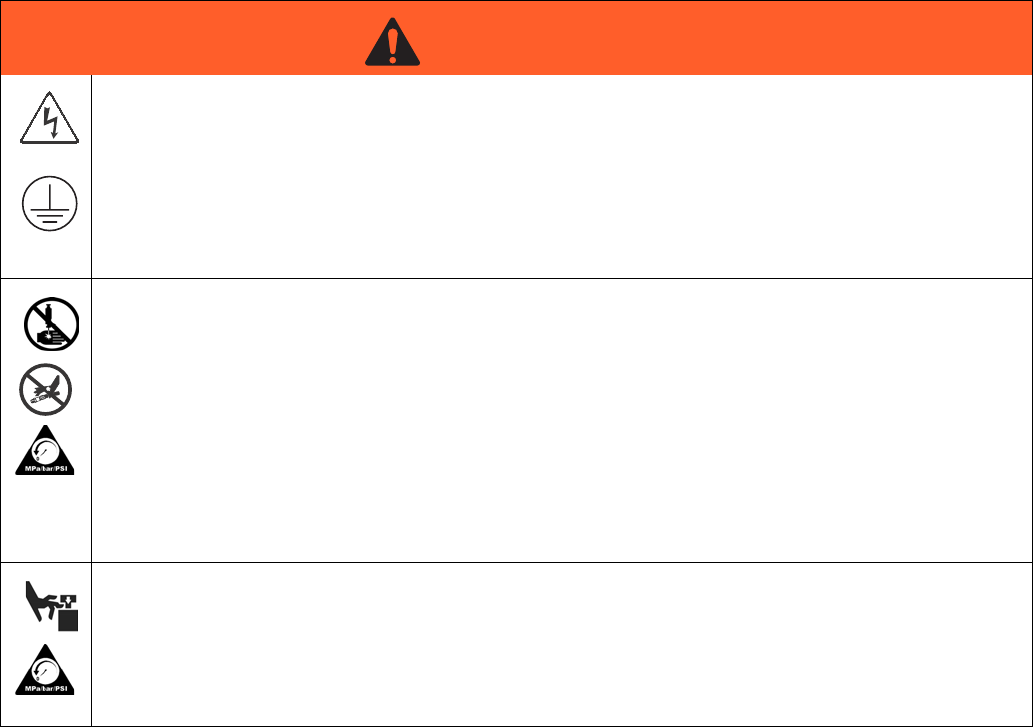
The following warnings are for the setup, use, grounding, maintenance, and repair of this equipment. The exclama-
tion point symbol alerts you to a general warning and the hazard symbols refer to procedure-specific risks. When
these symbols appear in the body of this manual, refer back to these Warnings. Product-specific hazard symbols and
warnings not covered in this section may appear throughout the body of this manual where applicable.
WARNINGWARNINGWARNING
WARNING
ELECTRIC SHOCK HAZARD
This equipment must be grounded. Improper grounding, setup, or usage of the system can cause elec-
tric shock.
• Turn off and disconnect power cord before servicing equipment.
• Connect only to grounded electrical outlets.
• Use only 3-wire extension cords.
• Ensure ground prongs are intact on power and extension cords.
• Do not expose to rain. Store indoors
SKIN INJECTION HAZARD
High-pressure fluid from dispensing device, hose leaks, or ruptured components will pierce skin. This
may look like just a cut, but it is a serious injury that can result in amputation. Get immediate surgical
treatment.
• Do not point dispensing device at anyone or at any part of the body.
• Do not put your hand over the fluid outlet.
• Do not stop or deflect leaks with your hand, body, glove, or rag.
• Follow the Pressure Relief Procedure when you stop dispensing and before cleaning, checking, or
servicing equipment.
• Tighten all fluid connections before operating the equipment.
• Check hoses and couplings daily. Replace worn or damaged parts immediately.
MOVING PARTS HAZARD
Moving parts can pinch, cut or amputate fingers and other body parts.
• Keep clear of moving parts.
• Do not operate equipment with protective guards or covers removed.
• Pressurized equipment can start without warning. Before checking, moving, or servicing equipment,
follow the Pressure Relief Procedure and disconnect all power sources.
Warnings
3A2894F 7
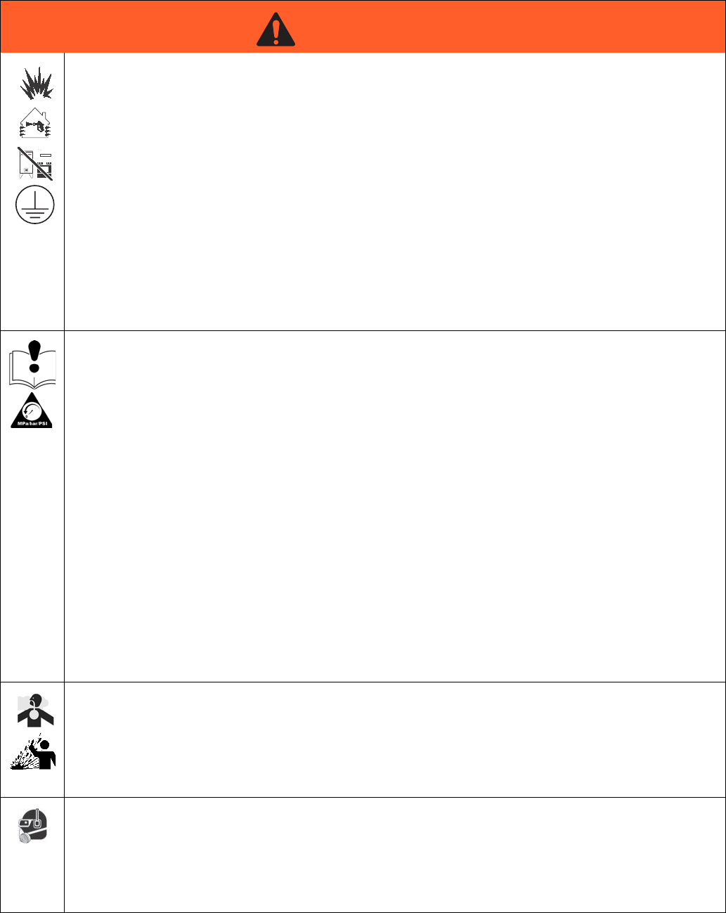
FIRE AND EXPLOSION HAZARD
Flammable fumes, such as solvent and paint fumes, in work area can ignite or explode. To help prevent
fire and explosion:
• Use equipment only in well ventilated area.
• Eliminate all ignition sources; such as pilot lights, cigarettes, portable electric lamps, and plastic drop
cloths (potential static arc).
• Keep work area free of debris, including solvent, rags and gasoline.
• Do not plug or unplug power cords, or turn power or light switches on or off when flammable fumes
are present.
• Ground all equipment in the work area. See Grounding instructions.
• Use only grounded hoses.
• Hold gun firmly to side of grounded pail when triggering into pail. Do not use pail liners unless they
are antistatic or conductive.
•Stop operation immediately if static sparking occurs or you feel a shock. Do not use equipment
until you identify and correct the problem.
• Keep a working fire extinguisher in the work area.
EQUIPMENT MISUSE HAZARD
Misuse can cause death or serious injury.
• Do not operate the unit when fatigued or under the influence of drugs or alcohol.
• Do not exceed the maximum working pressure or temperature rating of the lowest rated system
component. See Technical Data in all equipment manuals.
• Use fluids and solvents that are compatible with equipment wetted parts. See Technical Data in all
equipment manuals. Read fluid and solvent manufacturer’s warnings. For complete information
about your material, request MSDS from distributor or retailer.
• Do not leave the work area while equipment is energized or under pressure.
• Turn off all equipment and follow the Pressure Relief Procedure when equipment is not in use.
• Check equipment daily. Repair or replace worn or damaged parts immediately with genuine manu-
facturer’s replacement parts only.
• Do not alter or modify equipment. Alterations or modifications may void agency approvals and create
safety hazards.
• Make sure all equipment is rated and approved for the environment in which you are using it.
• Use equipment only for its intended purpose. Call your distributor for information.
• Route hoses and cables away from traffic areas, sharp edges, moving parts, and hot surfaces.
• Do not kink or over bend hoses or use hoses to pull equipment.
• Keep children and animals away from work area.
• Comply with all applicable safety regulations.
TOXIC FLUID OR FUMES HAZARD
Toxic fluids or fumes can cause serious injury or death if splashed in the eyes or on skin, inhaled, or
swallowed.
• Read MSDSs to know the specific hazards of the fluids you are using.
• Route exhaust away from work area. If diaphragm ruptures, fluid may be exhausted into the air.
• Store hazardous fluid in approved containers, and dispose of it according to applicable guidelines.
PERSONAL PROTECTIVE EQUIPMENT
Wear appropriate protective equipment when in the work area to help prevent serious injury, including
eye injury, hearing loss, inhalation of toxic fumes, and burns. This protective equipment includes but is
not limited to:
• Protective eyewear, and hearing protection.
• Respirators, protective clothing, and gloves as recommended by the fluid and solvent manufacturer
WARNINGWARNINGWARNING
WARNING
Important Isocyanate (ISO) Information
83A2894F
Important Isocyanate (ISO) Information
Isocyanates (ISO) are catalysts used in some two component materials.
Isocyanate Conditions
Material Self-ignition
Keep Components A and B
Separate
PRESSURIZED ALUMINUM PARTS HAZARD
Use of fluids that are incompatible with aluminum in pressurized equipment can cause serious chemical
reaction and equipment rupture. Failure to follow this warning can result in death, serious injury, or prop-
erty damage.
• Do not use 1,1,1-trichloroethane, methylene chloride, other halogenated hydrocarbon solvents or flu-
ids containing such solvents.
• Many other fluids may contain chemicals that can react with aluminum. Contact your material sup-
plier for compatibility.
WARNINGWARNINGWARNING
WARNING
Spraying or dispensing materials containing isocya-
nates creates potentially harmful mists, vapors, and
atomized particulates.
Read material manufacturer’s warnings and material
MSDS to know specific hazards and precautions
related to isocyanates.
Prevent inhalation of isocyanate mists, vapors, and
atomized particulates by providing sufficient ventila-
tion in the work area. If sufficient ventilation is not
available, a supplied-air respirator is required for
everyone in the work area.
To prevent contact with isocyanates, appropriate per-
sonal protective equipment, including chemically
impermeable gloves, boots, aprons, and goggles, is
also required for everyone in the work area.
Some materials may become self-igniting if applied
too thick. Read material manufacturer’s warnings and
material MSDS.
Cross-contamination can result in cured material in
fluid lines which could cause serious injury or damage
equipment. To prevent cross-contamination:
•Never interchange component A and component
B wetted parts.
• Never use solvent on one side if it has been con-
taminated from the other side.

Important Isocyanate (ISO) Information
3A2894F 9
Moisture Sensitivity of
Isocyanates
Exposure to moisture (such as humidity) will cause ISO
to partially cure; forming small, hard, abrasive crystals,
which become suspended in the fluid. Eventually a film
will form on the surface and the ISO will begin to gel,
increasing in viscosity.
NOTE: The amount of film formation and rate of crystal-
lization varies depending on the blend of ISO, the
humidity, and the temperature.
Changing Materials
NOTICE
Partially cured ISO will reduce performance and the
life of all wetted parts.
• Always use a sealed container with a desiccant
dryer in the vent, or a nitrogen atmosphere. Never
store ISO in an open container.
• Keep the ISO pump wet cup or reservoir (if
installed) filled with appropriate lubricant. The
lubricant creates a barrier between the ISO and
the atmosphere.
• Use only moisture-proof hoses compatible with
ISO.
• Never use reclaimed solvents, which may contain
moisture. Always keep solvent containers closed
when not in use.
• Always lubricate threaded parts with an appropri-
ate lubricant when reassembling.
NOTICE
Changing the material types used in your equipment
requires special attention to avoid equipment damage
and downtime.
• When changing materials, flush the equipment
multiple times to ensure it is thoroughly clean.
• Always clean the fluid inlet strainers after flushing.
• Check with your material manufacturer for chemi-
cal compatibility.
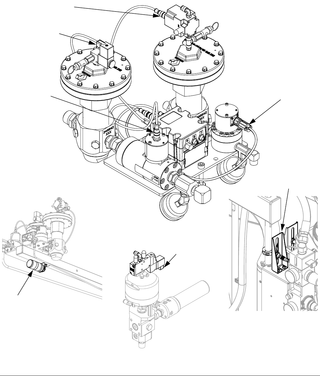
Component Identification
10 3A2894F
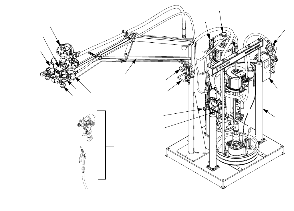
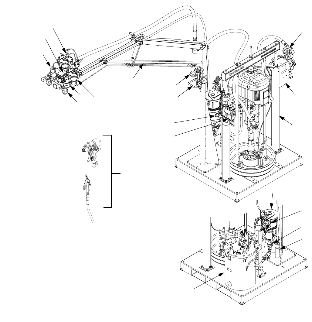
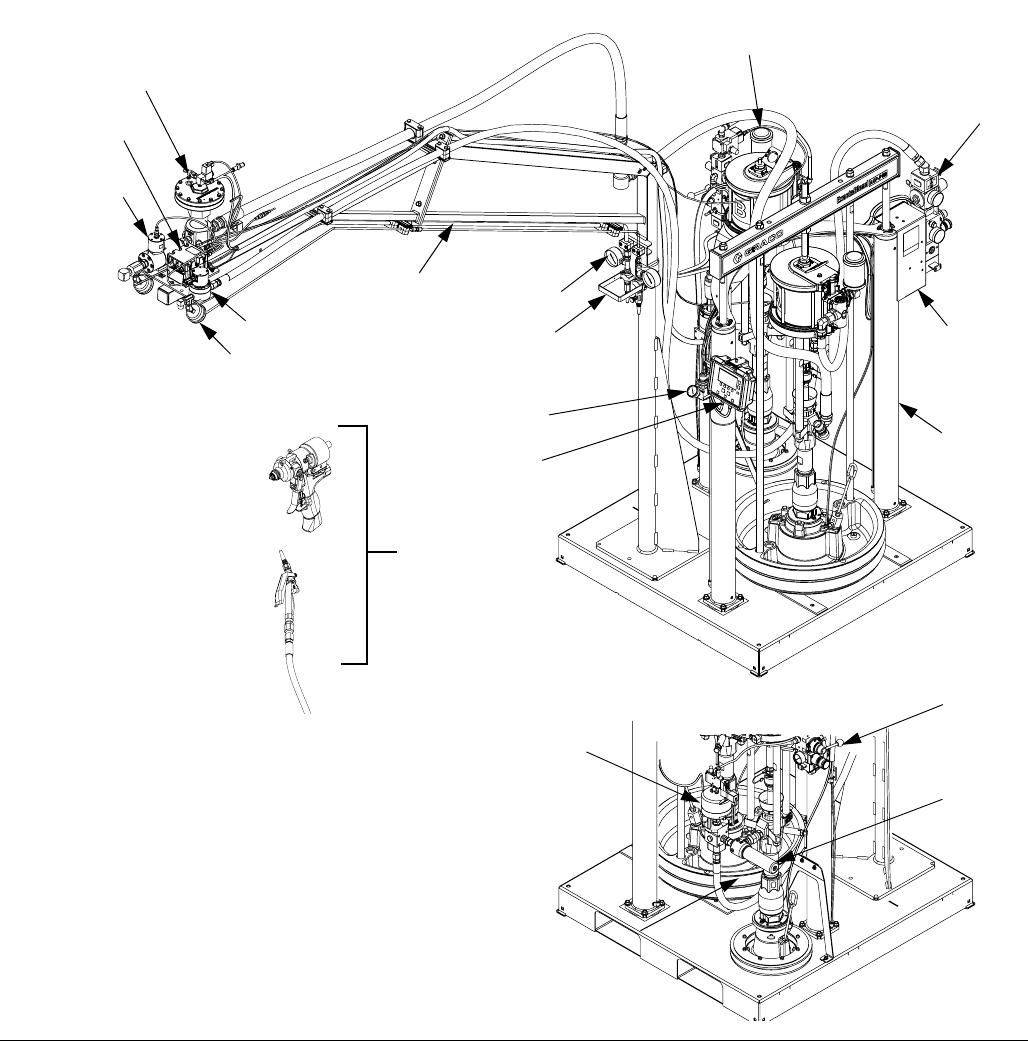
Component Identification
S100 Models
Key:
A Display Module (DM)
BBoom
C Ram - Base (A) Chemical*
D Ram - Catalyst (B) Chemical*
E Dispense Valve*
F Integrated Air Controls
G Electrical Enclosure
H Flow Meters*
J Fluid Regulator*
K Calibration Check Assembly
L Fluid Control Module (FCM)
M Material Pressure Gauges
N Catalyst (B) Filter
P Fluid Regulator Adjustment
Controls the pressure to the base (A) fluid regulator.
R Pressure Pot (U100 only)*
S Air Motor (U100 only)*
T Displacement Pump (U100 only)*
U Dosing Valve (P100 only)*
* Refer to specific component manual for more detailed
information.
FIG. 1: S100 Models
A
B
C
E
G
F
H
D
F
JK
L
M
J
M
H
P

Component Identification
3A2894F 13
Component Identification
14 3A2894F
Display Module (DM)
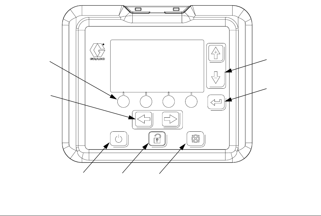
User Interface
Key:
BA System Enable/ Disable
Enables/disables the system. When the system is
disabled, dispense operation is disabled.
BB Soft Keys
Defined by application using the DM.
BC Cancel
Cancel a selection or number entry while in the process of
entering a number or making a selection.
BD Enter
Acknowledge changing a value or making a selection.
BE Lock/Setup
Toggle between run and setup screens. If setup screens
are password protected, button toggles between run and
password entry screen.
BF Field Selection
Navigate to another field when the DM is in setup mode.
These buttons have no function when the DM is in run
mode.
BG Increase / Decrease / Field Selection
Increase or decrease the selected value. Navigate to
another field.
FIG. 4: DM Component Identification - Front
BA BE BC
BB
BF
BD
BG

Component Identification
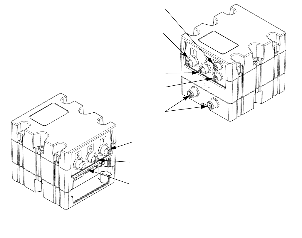
3A2894F 15
BH Model Number
Identification tag for the DM.
BJ CAN Cable Connections
Electrical connection for power and communication to
other GCA devices.
BK Module Status LEDs
Visual indicators to show the status of the DM:
Green Solid - Power provided.
Green Off - No power.
Yellow Flashing - Communication with other GCA
devices occurring.
Red Solid - Bad DM or machine is in critical status
Red Flashing - Wrong program uploaded.
BL Token/Battery Access Cover
Access cover for token and battery.
FIG. 5: DM Component Identification - Rear
BL
BH
BK
BJ

Component Identification
16 3A2894F
Main Display Components
The following figure calls out the navigational, status, and general informational components of each screen.
FIG. 6: Main Display Components
Current date and time
Current screen
Selection screen
Previous screen
Next screen
Function display
Faults, Status

Component Identification
3A2894F 17
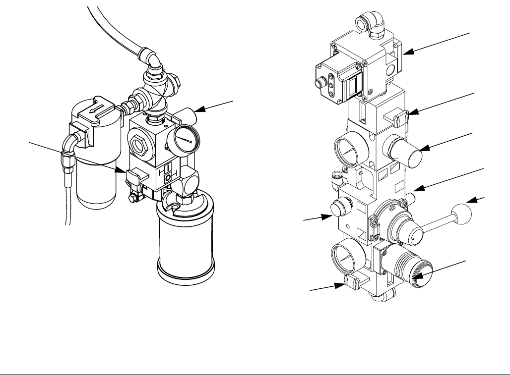
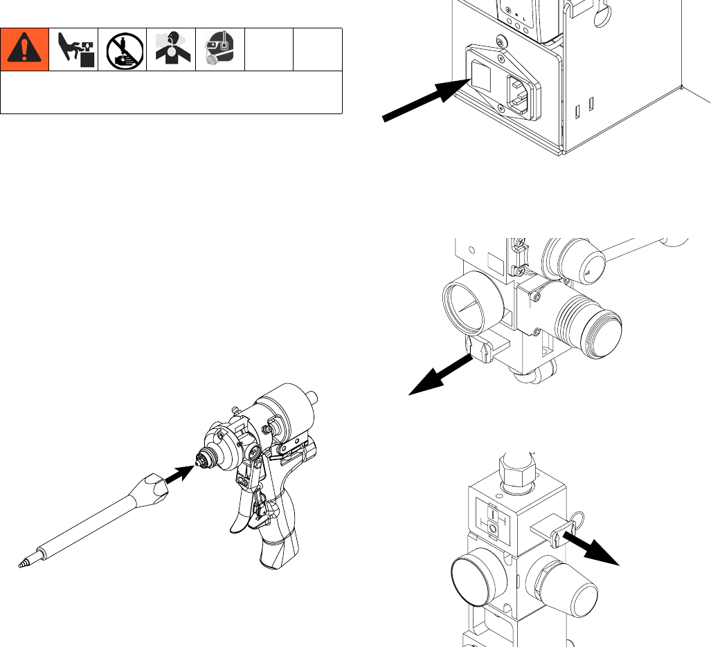
Electrical Enclosure
Key:
DA Power Switch
Turns electrical power on or off.
DB 24VDC Power Supply
Converts input power to 24 VDC.
FIG. 7: Electrical Enclosure
DA
DB
Component Identification
18 3A2894F
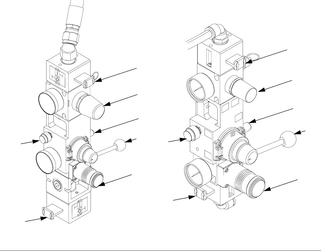
Integrated Air Controls
Key:
CA Main Air Slider Valve
Turns air on and off to the entire system. When closed,
the valve relieves pressure downstream.
CB Ram Air Regulator
Controls the ram up and down pressure and blowoff
pressure.
CC Ram Director Valve
Controls the ram direction.
CD Exhaust Port with Muffler
CE Air Motor Regulator
Controls the air pressure to the motor.
CF Air Motor Slider Valve
Turns air on and off to the air motor. When closed, the
valve relieves air trapped between it and the motor. Push
the valve in to shutoff.
CG Blowoff Button
Turns air on and off to push the platen out of an empty
drum.
CJ Catalyst Air Slider Valve
Turns air on and off to the catalyst motor only. When
closed, the valve relieves pressure down stream.
CK Voltage to Pneumatic Regulator (V/P)
Electrically controlled air regulator.
FIG. 8: Integrated Air Controls
CB
CC
CD
CE
CF
CA
CG
Base (A) Side
All Models Catalyst (B) Side
S100 Models
CB
CC
CD
CG
CJ
CE
CF
Component Identification
20 3A2894F
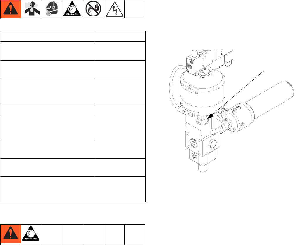
Fluid Control Module (FCM)
Key:
EA Port 1 - Air Shut off Valve
Controls the air to the base (A) material regulator.
Port 1 - Low Level Sensors (Optional)
Low level input for the both materials. Refer to
Accessories and Kits, page 60, for more details.
Includes splitter.
EB Port 2 - Flow Meters
Base (A) and Catalyst (B) flow meter input. Includes
splitter
EC Port 3 - Solenoid Valve (P100 only)
To open and close the dosing valve.
ED Port 4 - Voltage to Pneumatic (V/P) Regulator
Controls the air to the catalyst (B) material regulator.
EE Port 5 - Audible Light Tower (Optional)
Visual and audible indicator of machine status. Refer to
Accessories and Kits, page 60, for more details.
EF Port 6 - Not Used
EG Port 7 - Not Used
EH CAN Connection
Supplies power and communication to GCA components.
FIG. 10: FCM
EG
EF
EE
EC
EA
EB
ED
EH
Component Identification
3A2894F 21
FIG. 11: Component Connection Reference from FCM
EE
EA
EB
ED
EB
EA
Component Connection Reference from
FCM (S100 Model Shown)
EC
Installation
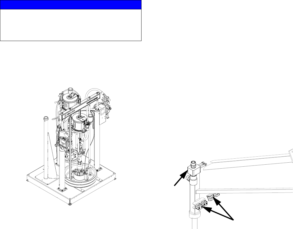
22 3A2894F
Installation
1. Locate the Machine Base.
Locate the machine on a level surface. Refer to Dimen-
sions, page 76, for space requirements.
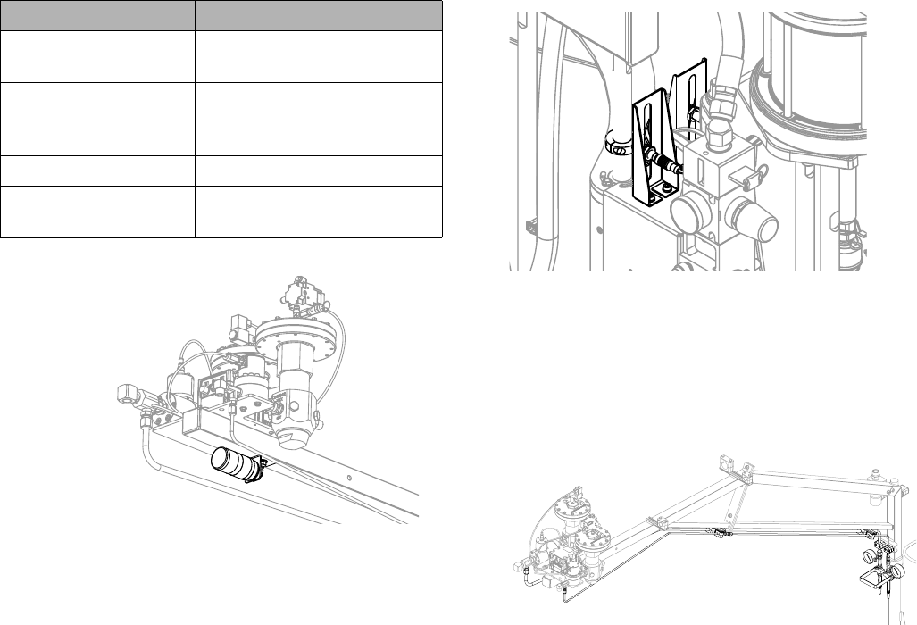
2. Assemble the Hose Clamps
and Swivel Assembly onto
the Boom Base.
a. Torque the swivel assembly fasteners to 24 ft-lb
(33 N•m).
b. Hand tighten all hose clamps.
NOTE: Refer to steps 8 and 10 for visual clarity of hose
clamp placement.
NOTICE
To avoid flow meter malfunction, do not use PTFE
tape on NPT threads. Only apply pipe sealant, Loc-
tite® #565 or equivalent, to all NPT threads when
installing.
S100 Shown
Calibration Check only
Swivel
Assembly
Installation
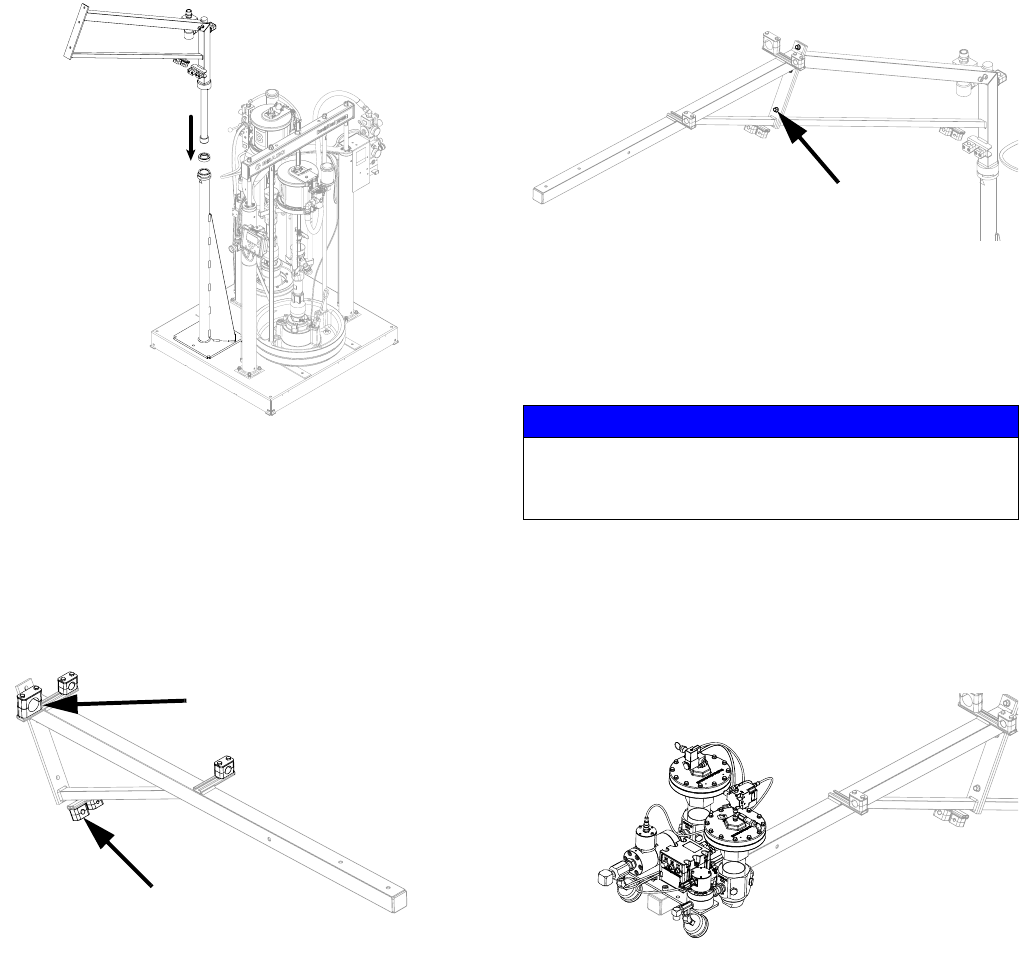
3A2894F 23
3. Install the Boom Base onto
the Machine Base.
Slide the boom base into the machine base mast.
4. Assemble the Hose Clamps
onto the Front Boom Arm.
Hand tighten all hose clamps.
NOTE: Refer to steps 8 and 10 for visual clarity of hose
clamp placement.
5. Install the Front Boom Arm
onto the Boom Base.
Torque all fasteners to 24 ft-lb (33 N•m).
6. Install the Fluid Plate onto the
Front Boom Arm.
a. Torque the fluid plate fasteners to 24 ft-lb
(33 N•m).
b. Install the fluid regulators if removed for installa-
tion.
Calibration check only
Resin Hose Clamp
NOTICE
Injury may occur if the fluid plate is lifted by only one
person. Use a hoist, multiple people, or remove the
fluid regulators prior to installation.
(3) Places
Installation
24 3A2894F
7. Calibration Check Only:
Install the Calibration Check
Assembly and Material Tubes
onto the Boom Assembly.
a. Tighten all fittings to prevent leaking.
b. Tighten all hose clamps to secure material lines.
NOTE: For additional assembly details, refer to the
ExactaBlend AGP Advanced Glazing Proportioner -
Accessories, Instructions manual.
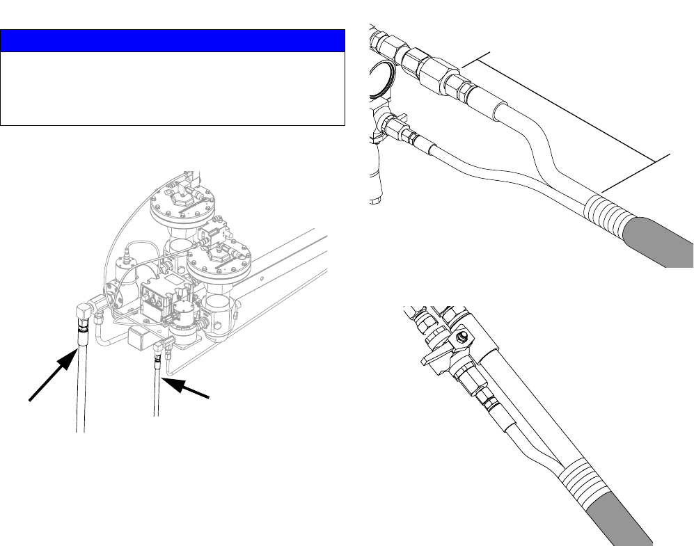
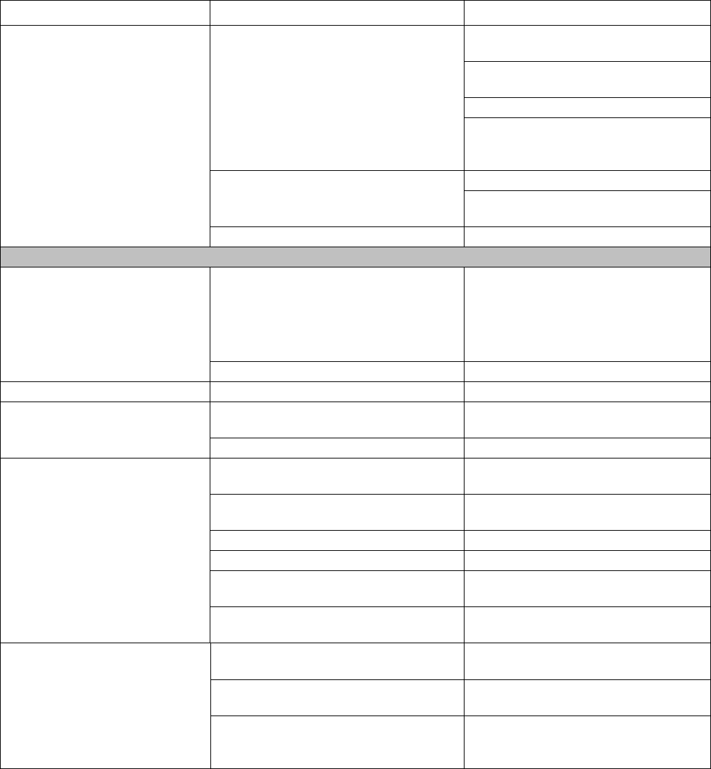
8. Route and Connect the
Base (A) Material Hoses.
a. Tighten all fittings to prevent leaking.
b. Tighten all hose clamps to secure material lines.
S100 Shown
Installation
3A2894F 25
9. P100 Only: Install the Dosing
Valve.
a. Tighten all fittings to prevent leaking.
b. Install the air supply from the catalyst integrated
air controls.
c. Connect the solenoid cable from port “3” of the
FCM. Refer to Fluid Control Module (FCM),
page 20. Allow enough length for lifting the ram
out of material container.
Label “100”
Installation
26 3A2894F
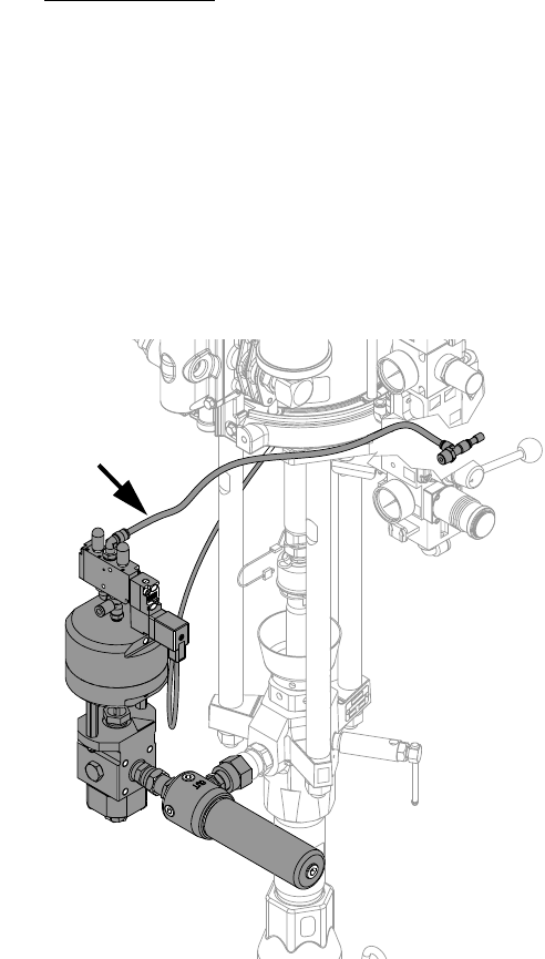
10.Route and Connect the Cata-
lyst (B) Material Hose.
a. Tighten all fittings to prevent leaking.
b. Tighten all hose clamps to secure material lines.
S100 Shown
U100 Shown
P100 Shown
Installation
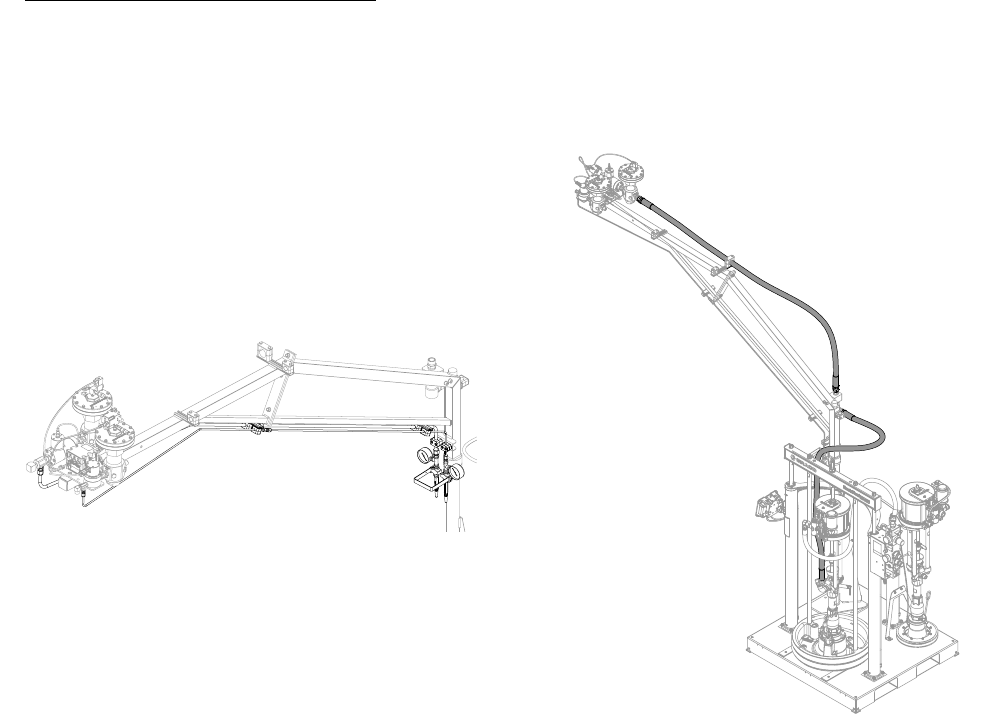
3A2894F 27
11.Route and Connect the Air
Hoses and Electrical Lines.
Secure the electrical lines to the boom using electrical
tape or zip ties.
NOTE: Securing the ground cable to the fluid plate is
required for the proper grounding of the machine.
NOTE: S100 and U100 models are shown below. For
P100 models, the V/P is located on the catalyst air con-
trols. Refer to Integrated Air Controls, page 18.
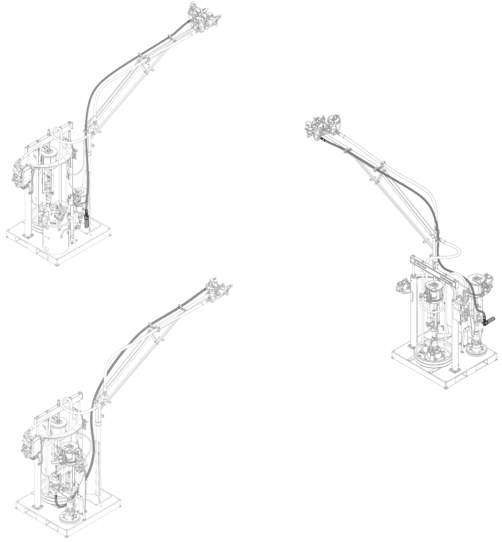
12.Assemble the Base (A) Mate-
rial Whip Hose.
Tighten all fittings to prevent leaking.
Label “102”
Label “103”
CAN Cable
Ground Cable
S100 Shown
Dispense End
Machine End
Installation
28 3A2894F
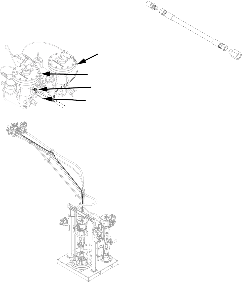
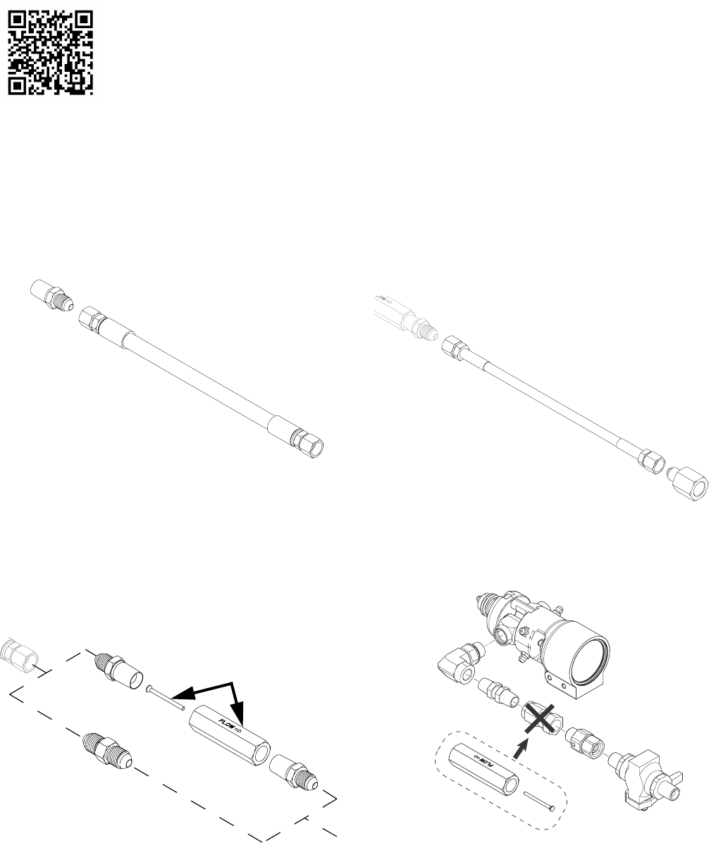
13.Assemble the Catalyst (B) Material Whip Hose.
Refer to PKE 2863 found at http://graco.custhelp.com/app/answers/detail/a_id/2863 or by utilizing the QR code below
for recommended hose size configurations, pin sizes, and calibration numbers. Tighten all fittings to prevent leaking.
NOTE: Refer to Restrictor Kit, 24R804, page 61, for purchase. Restrictor pin size is for typical applications and are
for reference only. It may be necessary to install other pins or configurations to obtain balanced pressures.
#1 = 0.094 in. (2.4 mm) • #2 = 0.098 in. (2.5 mm) • #3 = 0.102 in. (2.6 mm)
NOTE: Refer to Catalyst (B) Hoses, page 61, for additional hose sizes available.
a. Select the fluid plate to restrictor housing hose.
Install the adapter.
b. Select the restrictor pin or union.
U100 with MD2: Install the union to the fluid
plate to restrictor housing hose. If utilizing the
restrictor pin assembly, the restrictor pin assem-
bly will be installed in step d.
All other Configurations: Install the restrictor
pin assembly or union to the fluid plate to
restrictor housing hose.
c. Select the restrictor housing to dispense valve
hose. Install the restrictor housing to dispense
valve hose to the restrictor pin assembly or
union.
d. U100 with MD2: If utilizing the restrictor pin
assembly, replace the swivel union found on the
MD2 with the restrictor pin assembly.
Note the orientation of
pin and pin housing.
Installation
3A2894F 29
14.Connect the Catalyst (B) and
Base (A) Material Whip Hoses
to the Fluid Plate.
a. Tighten all fittings to prevent leaking.
b. Slide protective sleeve over base and catalyst
hoses.
c. MD2: Tape sleeve 8 in. (20 cm) behind the high
volume fitting to allow adequate movement of
the gun handle.
Ultra-Lite: Tape sleeve just behind manifold
block.
d. Pull the other end of the protective sleeve tightly
and secure with electrical tape.
NOTICE
Damage to the moisture-lok hoses may result in
moisture sensitive material to cure within the hose. To
avoid machine damage, avoid damaging the protec-
tive coating on the moisture-lok hoses.
Catalyst
Base
8 in. (20 cm)
Installation
30 3A2894F
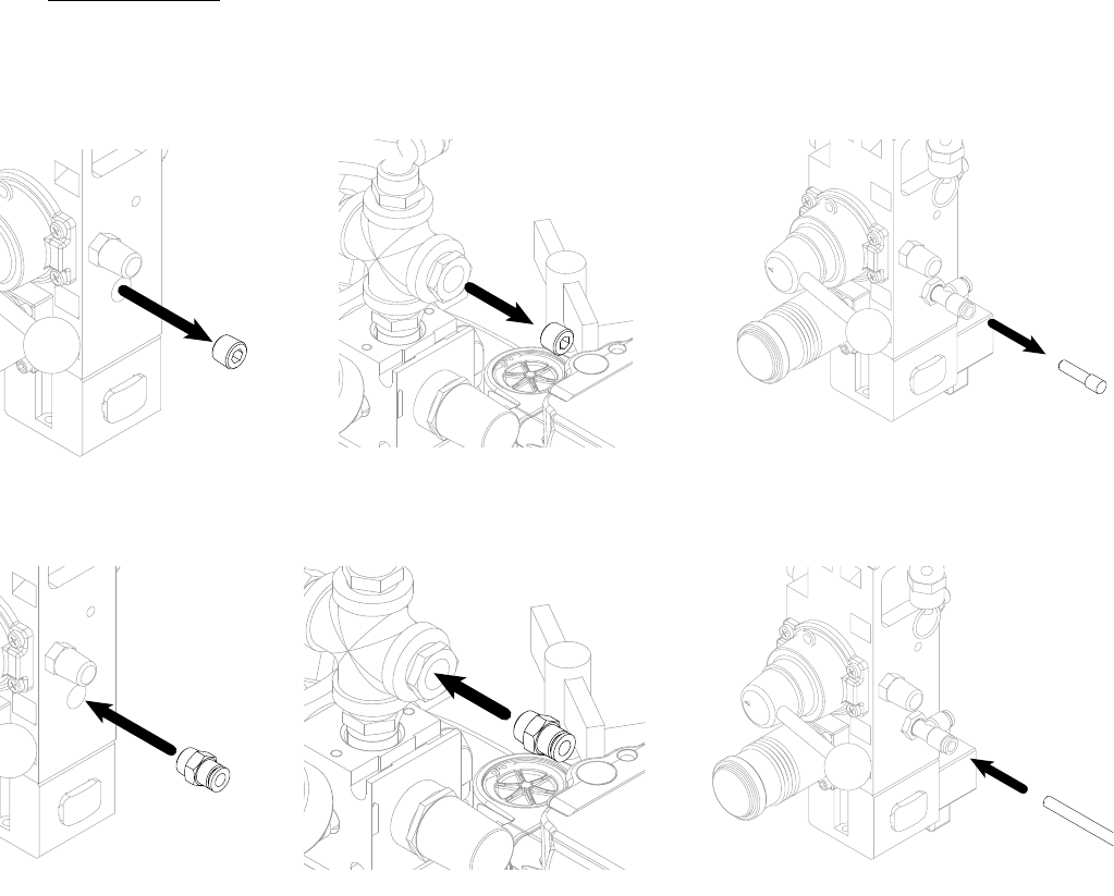
15.MD2 Only: Connect the Air
Fitting and Route the Air
Hose.
a. Remove the plug located on the catalyst (B) integrated air control.
b. Install the air fitting if required. Use sealant on the threads and tighten to prevent leaking.
c. Route the air line beside the other air hoses that were routed in step 11.
S100 Shown U100 Shown P100 Shown
S100 Shown U100 Shown P100 Shown
Installation
3A2894F 31
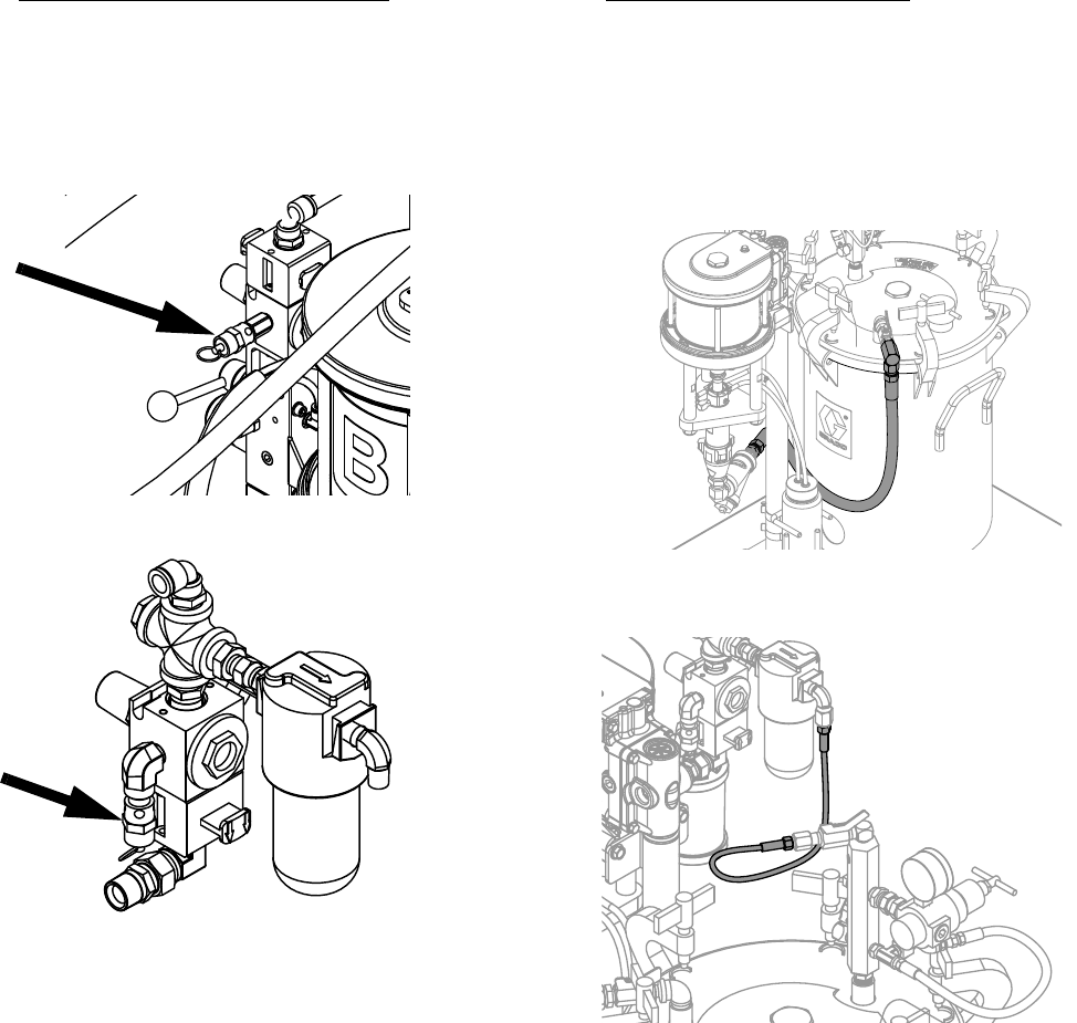
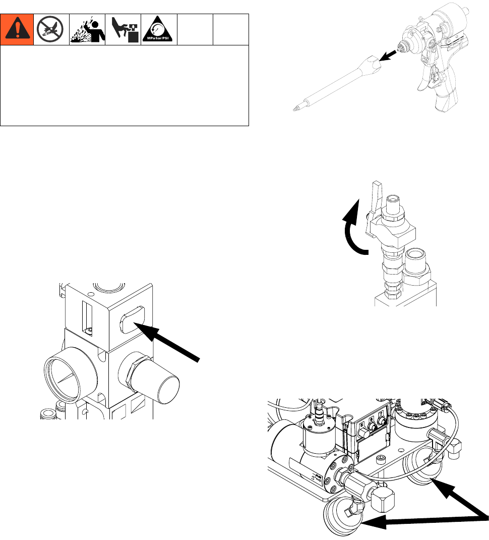
16.Ultra-lite Tri-core Only:
Replace the Relief Valve on
Both Integrated Air Controls.
Replace the standard relief valve found on both the
base (A) and catalyst (B) integrated air controls with the
relief valve for the Ultra-lite Tri-core dispense valve.
17.U100 Models Only: Locate
and Connect the Pressure
Pot
a. Locate the pressure pot on the machine base.
b. Connect the chemical line from the pressure pot
to the fluid filter inlet using fitting provided.
c. Connect the air line from the Base (A) Inte-
grated Air Controls to the pressure pot.
U100 Shown
S100 Shown
Installation
32 3A2894F
18.Install Accessories.
Refer to the ExactaBlend AGP Advanced Glazing Pro-
portioner - Accessory Kits manual for details.
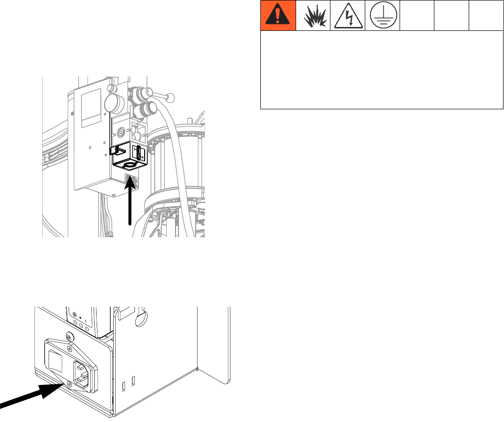
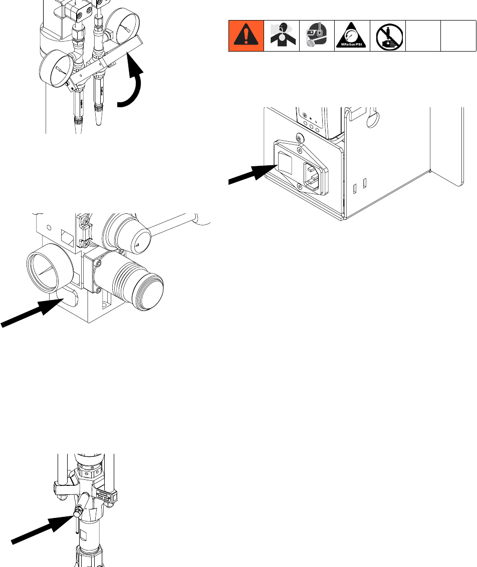
19.Connect Air to the Machine.
NOTE: Air inlet port size is 3/4 npt (f).
20.Connect Electrical Power to
Machine.
Connect the power cord to the electrical enclosure.
Grounding
Machine: Grounded through customer supplied power
cord.
Fluid supply container: follow local code.
Solvent pails used when flushing: follow local code.
Use only conductive metal pails, placed on a grounded
surface. Do not place the pail on a nonconductive sur-
face, such as paper or cardboard, which interrupts
grounding continuity.
To maintain grounding continuity when flushing or
relieving pressure: hold metal part of the gun/dispense
valve firmly to the side of a grounded metal pail, then
trigger the gun/valve.
The equipment must be grounded to reduce the risk
of static sparking and electric shock. Electric or static
sparking can cause fumes to ignite or explode.
Improper grounding can cause electric shock.
Grounding provides an escape wire for the electric
current.
Setup
3A2894F 33
Setup
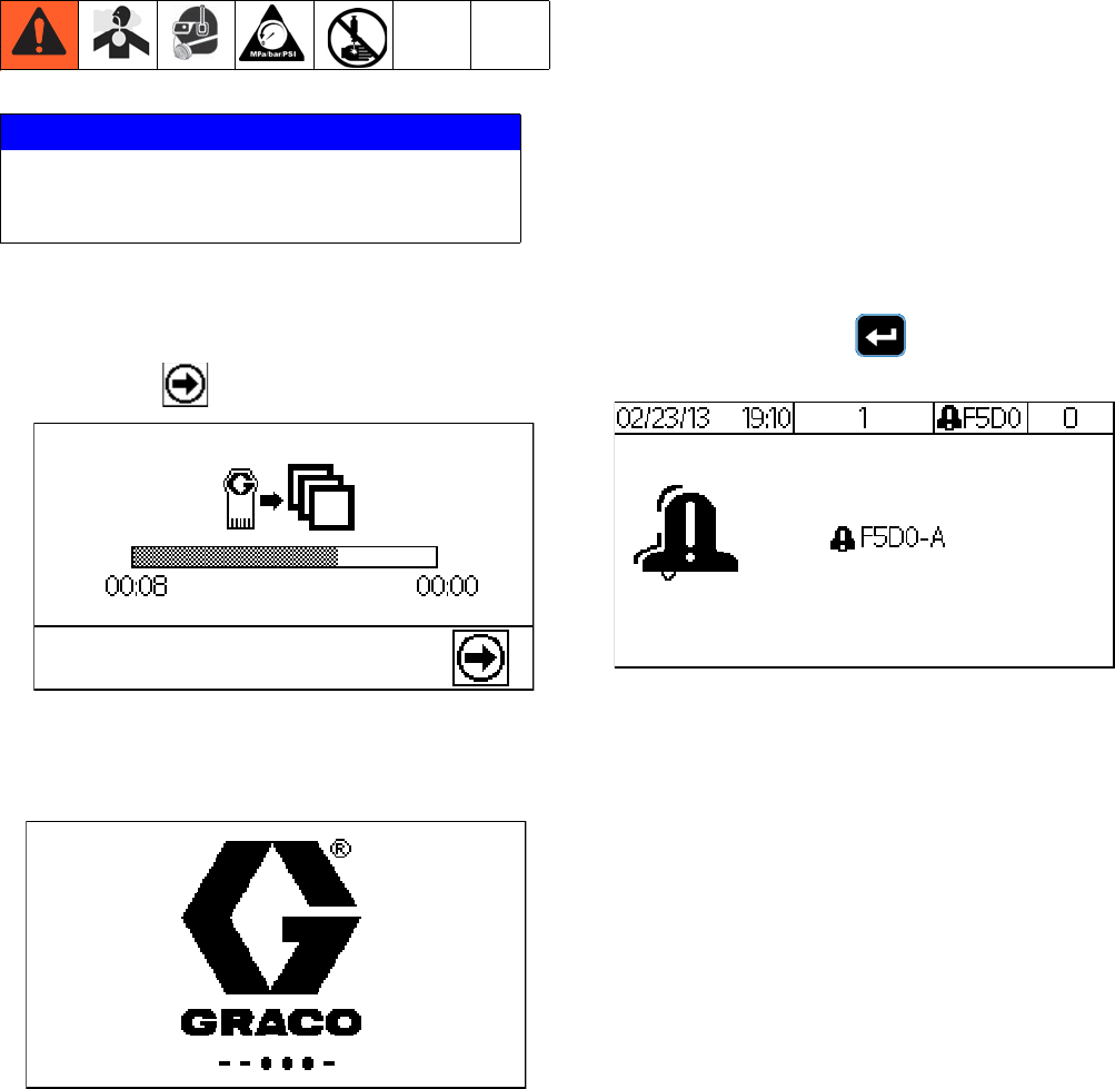
When software is updated on the DM, the software is
then automatically updated on all connected GCA com-
ponents. A status screen is shown while the software is
updating to indicate the progress. When the status bar is
complete, press to continue.
When the main electrical power is turned on, the splash
screen will be displayed until communication and initial-
ization is complete.
The DM will display an error message when initialization
is complete. This error occurs because the machine has
not been calibrated. Press to acknowledge the
error and continue with the setup procedure.
NOTICE
To prevent damage to soft key buttons, do not press
the buttons with sharp objects such as pens, plastic
cards, or fingernails.
Setup
34 3A2894F
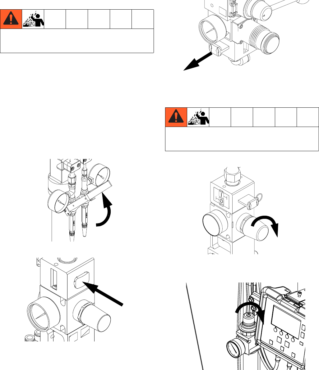
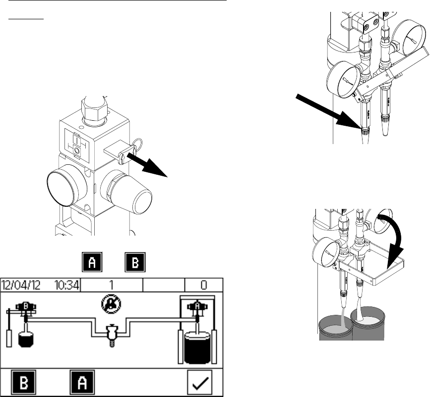
1. Purge Material Lines.
a. Load material.
Ram: Perform the “Change Drums” procedure
in the Air-Powered Ram manual.
Pressure Pot: Perform “Filling the Tank” proce-
dure in the 5-, 10-, and 15-Gallon Pressure
Tanks manual. An agitator is recommended for
urethane applications utilizing a pressure pot.
Set the agitator to 25-50 rpm.
b. Calibration Check Assembly Only: Close the
calibration check assembly.
c. Close the base (A) air motor slider valve.
d. Open the base (A) main air slider valve.
e. Set the base (A) air motor regulators to 10 psi
(70 kPa, 0.7 bar).
f. Set the fluid regulator adjustment to 40 psi
(280 kPa, 2.8 bar).
g. Place the base (A) hose end into a waste con-
tainer.
To avoid personal injury or machine damage, adjust all
air regulators counter-clockwise prior to turning the
main air on.
To avoid personal injury or machine damage, do not
exceed 25 psi on the base (A) material until a steady
flow of material has been established.
Setup
3A2894F 35
h. Activate on the DM.
i. Open the base (A) air motor slider valve.
j. Increase the base (A) air motor regulator as
required to have material flow out of the hose.
k. Dispense the material into the waste container
until the base (A) material hose is purged and
free of air.
l. Deactivate on the DM.
m. Close the base (A) air motor slider valve.
n. Repeat steps a through m for the catalyst (B)
hose. Refer to Integrated Air Controls,
page 18, for visual clarity.
NOTE: Activate on the DM when prompted and all
slider valves refer to the catalyst (B) air controls.
Setup
36 3A2894F
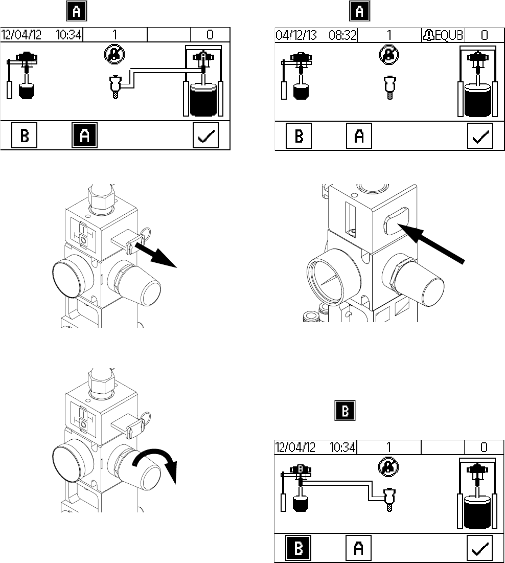
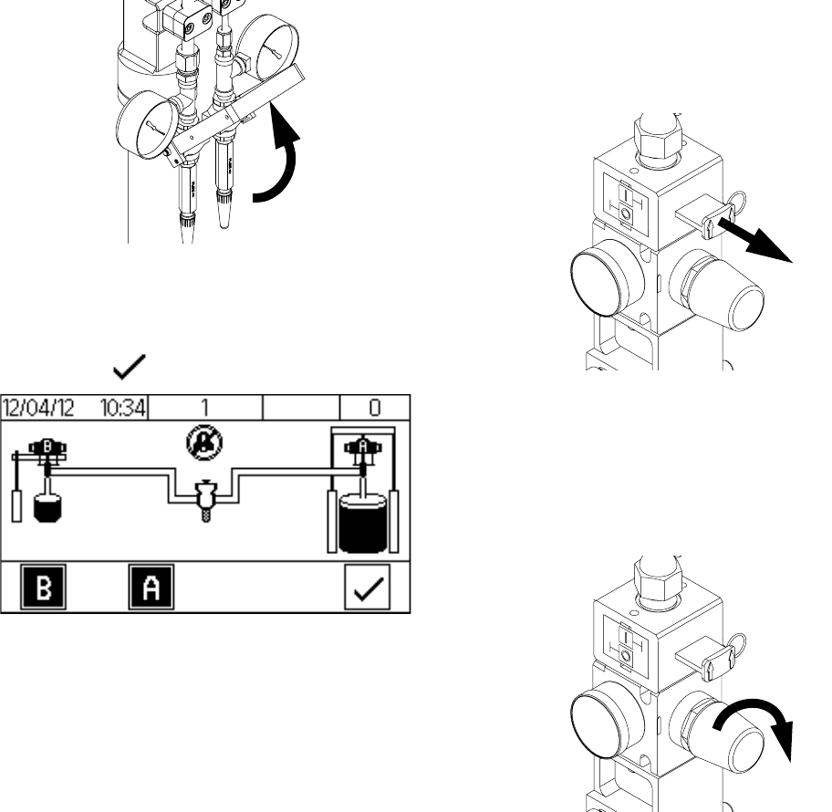
2. Connect the dispense appli-
cator.
MD2:
a. Connect both base (A) and catalyst (B) material
hoses to the dispense applicator.
b. Activate both and on the DM.
c. Open the catalyst (B) ball valve and dispense
material into a waste container until the dis-
pense valve has been purged and is free of air.
d. Activate on the DM.
Ultra-lite:
a. Connect the base (A) hose to the base (A) inlet
fitting.
b. Connect the catalyst (B) hose to the catalyst (B)
inlet fitting.
c. Open the catalyst (B) ball valve and dispense
material into a waste container until the dis-
pense valve has been purged and is free of air.
d. Close the catalyst (B) ball valve and dispense
material into a waste container until only
base (A) is present.
Setup
3A2894F 37
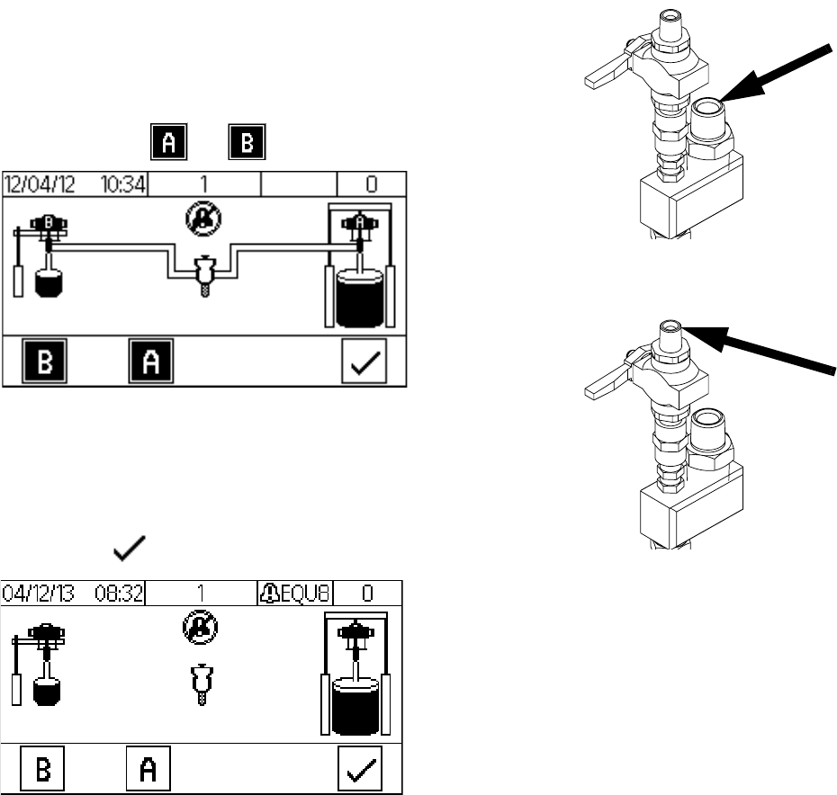
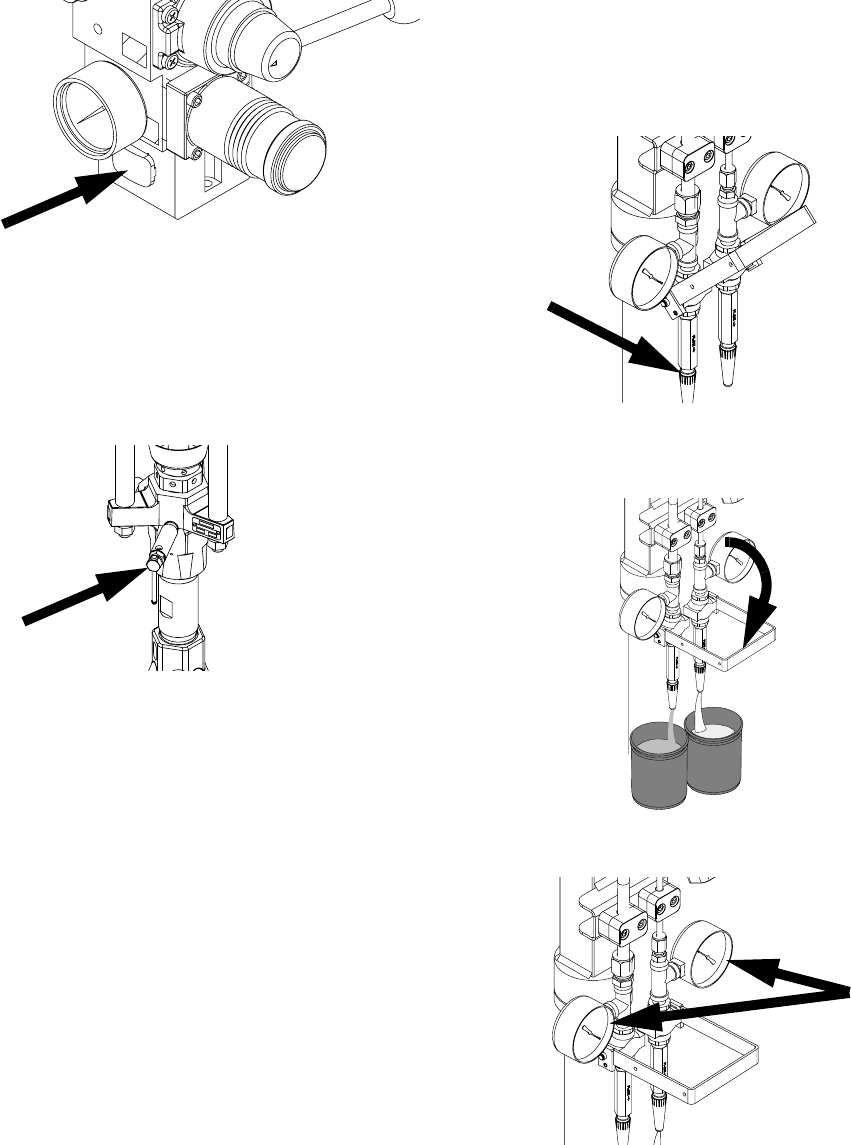
3. Calibration Check Assembly
Only: Purge material lines to
the calibration check assem-
bly.
a. Open the base (A) and catalyst (B) air motor
slider valves.
b. Activate both and on the DM.
c. Place a waste container underneath the calibra-
tion check assembly.
d. Remove the JIC caps from the calibration check
assembly.
e. Open the calibration check assembly.
Setup
38 3A2894F
f. Dispense the material into the waste container
until both the base (A) and catalyst (B) material
lines have been purged and are free of air.
g. Close the calibration check assembly.
h. Clean the nozzles of the calibration check
assembly and install the JIC caps.
i. Activate on the DM.
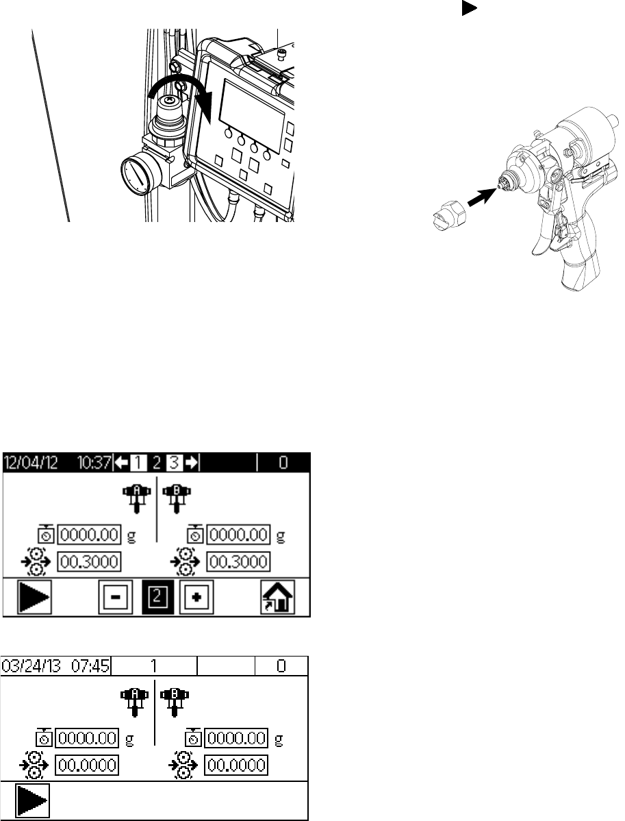
4. Calibrate the machine.
Perform the following procedure during initial setup of
the machine, if the flow meters were replaced, or if the
machine needs to be recalibrated.
a. Engage the trigger lock.
b. Open the base (A) and catalyst (B) air motor
slider valves.
c. Set the base (A) and catalyst (B) air motor regu-
lators.
MD2 or Ultra-lite with flexible hose:
70 psi (480 kPa, 4.8 bar).
Ultra-lite with Tri-core:
85 psi (586 kPa, 5.9 bar)
Setup
3A2894F 39
d. Set the fluid regulator adjustment to 40 psi
(280 kPa, 2.8 bar).
e. Place two separate containers on two separate
scales and zero the scales. These containers
will be used in step j.
NOTE: Weight units of the scales are to be set as
grams.
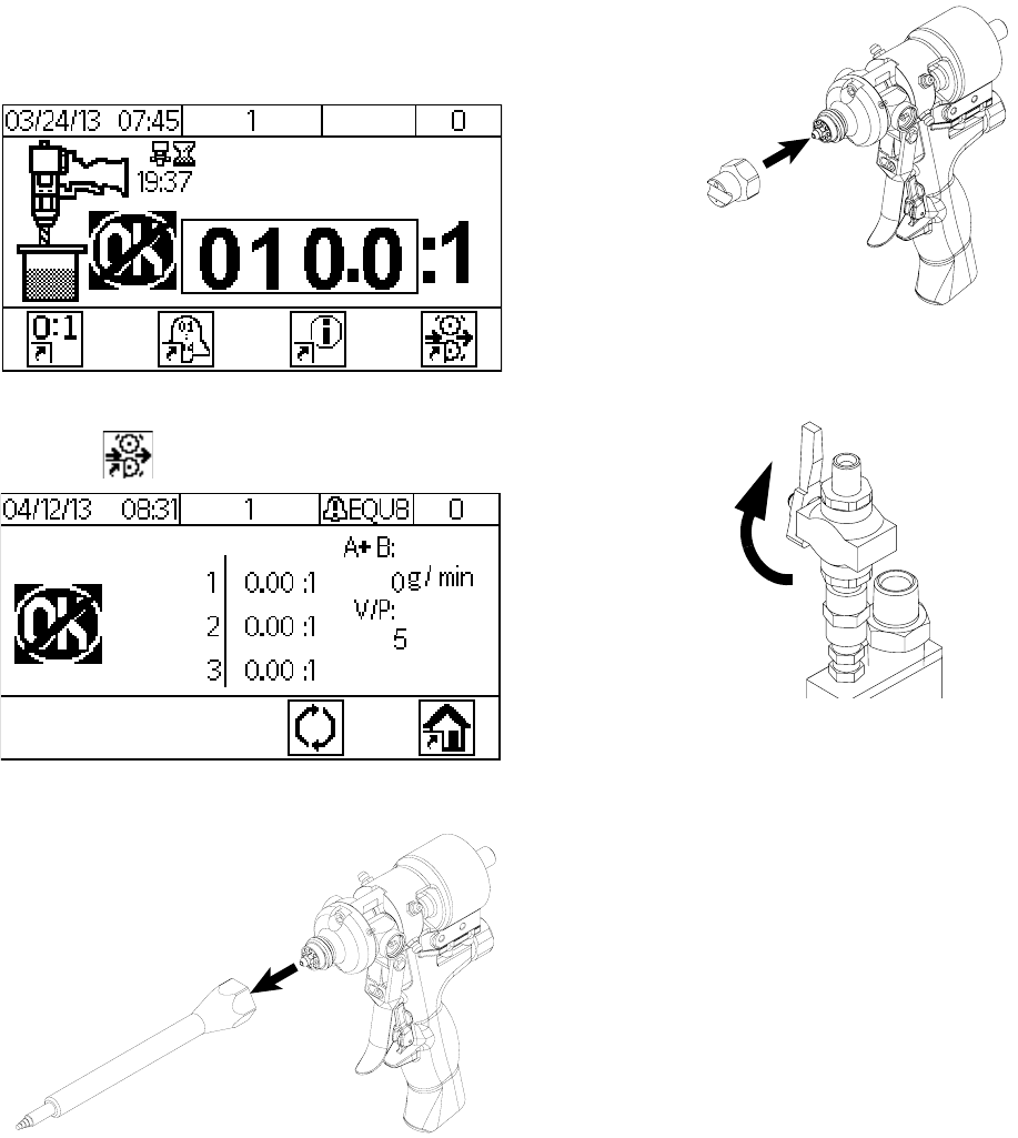
f. Navigate to setup Screen 2.
NOTE: Screen 2 is already shown if this procedure is
performed during the initial setup of the machine.
g. Activate to signal the machine of the fol-
lowing calibration shot.
h. MD2: Install the calibration nozzle onto the dis-
pense applicator.
i. Disengage the trigger lock.
Screen 2 - Recalibration
Screen 2 - Initial Calibration

Setup
40 3A2894F
j. Dispense the chemicals into two separate con-
tainers.
MD2: Chemical will be dispensed through the
applicator.
Ultra-lite: Chemical will be dispensed through
the calibration check assembly.
k. Continue to dispense the chemical into the con-
tainers until both status bars are complete.
NOTE: If the light tower is installed, a green light will be
illuminated when the status bars are complete.
l. Weigh both containers separately and input the
values of both chemicals into setup Screen 2.
NOTE: To change a value in a desired field, perform the
following.
• Press or to highlight the
desired field to be changed.
• Press to activate the desired field or to
activate/deactivate an option.
• Press or to change the value of the
selected field.
• Press to set the value.
NOTE: Weight units are in grams.
Setup
3A2894F 41
m. Press to signal the machine that the cali-
bration procedure is complete. The machine will
automatically calculate the K factor of both
materials.
n. Engage the trigger lock.
o. MD2: Remove the calibration nozzle and install
a static mixer on the dispense valve.
p. Navigate to the Home screen.
5. Set the Display Module (DM).
Perform the following tasks to fully setup the DM. Refer
to Appendix A - DM Icons Overview, page 64, for clar-
ity.
a. Define general system settings. See Screen 3,
page 66.
b. Define specific system settings. See Screen 1,
page 66.
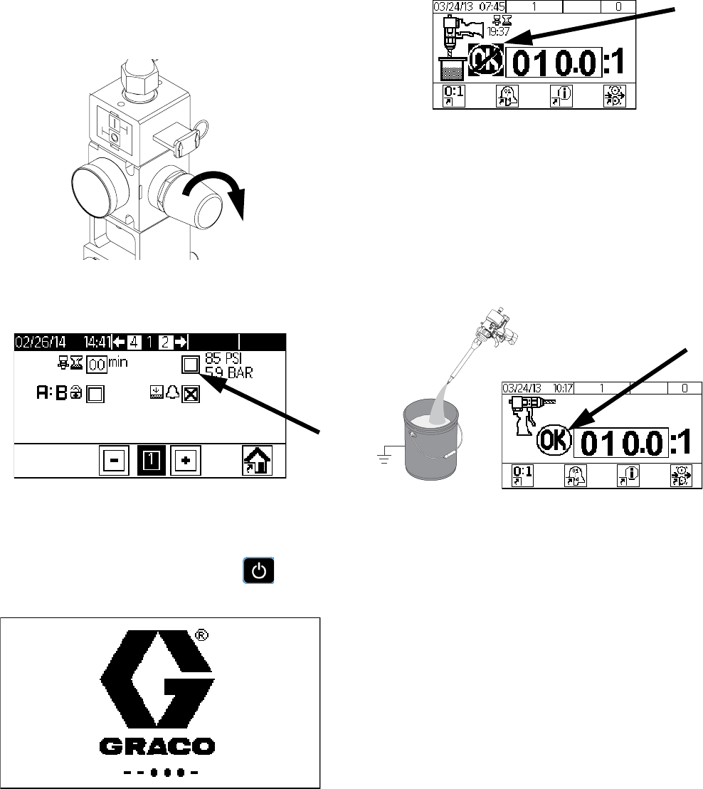
c. P100 with Ultra-Lite Tri-core Mixer: Select the
85 psi (5.9 bar) option box. See Screen 1,
page 66.
Startup
42 3A2894F
Startup
1. Engage the trigger lock.
2. Install the static mixer or nozzle onto the dispense
applicator. See specific applicator manual for
details.
NOTE: Cutting more than two outlet steps on the static
mixer may increase the chance of the mixing elements
being pushed out of the static mixer.
NOTE: If using the mixer element kit 24T035, assemble
the sleeve onto the MD2 dispense applicator prior to fas-
tening the 1/4 NPT outlet adapter. Hand tighten the 1/4
NPT outlet adapter.
3. Turn the power on at the electrical enclosure.
4. Open the base (A) and catalyst (B) main air slider
valves.
5. Open the base (A) and catalyst (B) air motor slider
valves.
Do not operate machine without all covers and
shrouds in place.
Startup
3A2894F 43
6. Verify the base (A) and catalyst (B) air motor regula-
tors are set to the correct pressure.
MD2 or Ultra-lite with flexible hose:
70 psi (480 kPa, 4.8 bar).
Ultra-lite with Tri-core:
85 psi (586 kPa, 5.9 bar)
7. P100 with Ultra-Lite Tri-core Mixer: Verify that the
85 psi (5.9 bar) option box is selected. Refer to
Screen 1, page 66.
8. Verify the ram director valve is set to lower the ram.
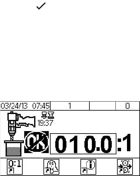
9. The DM will show a standby screen when power is
first supplied to the machine. Press to go to
the Home screen.
NOTE: The Home screen will indicate “Not OK” and the
light tower, if installed, will illuminate red until the next
step is completed.
10. Disengage the trigger lock.
NOTE: If a new static mixer has been installed, a base
purge is recommended to prevent side walling. Perform
Base Purge, page 44.
11. Hold a metal part of the gun firmly to a grounded
metal pail. Trigger the gun until the Display Module
shows “OK” and the light tower, if installed, illumi-
nates green.
NOTE: Additional dispensing may be required in order
to ensure a good mixture.
r_255179_purge
Base Purge
44 3A2894F
Base Purge
Base purge results in the purging of the base (A) chemi-
cal through the dispense valve. Base purging prevents
mixed material within the dispense applicator from cur-
ing. The machine will remain pressurized and electri-
cally connected.
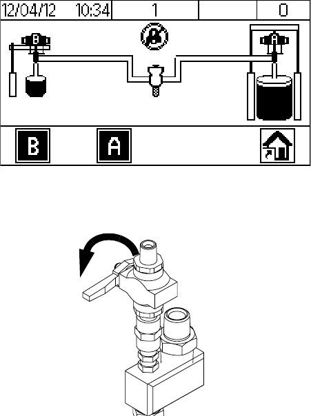
1. Navigate to the Purge/Prime screen.
NOTE: Verify both pumps are activate.
2. Close the catalyst (B) ball valve located near the
dispense applicator.
3. Dispense material into a waste container until only
the base (A) chemical is present.
4. Engage the trigger lock.

Base Purge
3A2894F 45
Pressure Relief Procedure
46 3A2894F
Pressure Relief
Procedure
1. If electrical power is supplied to the machine,
perform Base Purge, page 44.
If electrical power is not supplied to the
machine, continue to the next step.
2. S100 and P100: Close the base (A) and catalyst (B)
air motor slider valves.
U100: Close the base (A) air motor slider valve and
the supply ball valve on the pressure pot. Bleed the
air from the pressure pot by opening the manual
bleed valve.
MD2:
a. Remove the static mixer.
b. Open the catalyst (B) ball valve located near the
dispense applicator.
c. Disengage the trigger lock.
d. Trigger the gun to relieve pressure into a waste
container.
e. Verify the pressure gauges display “0”.
This equipment stays pressurized until pressure is
manually relieved. To help prevent serious injury from
pressurized fluid, such as skin injection, splashing
fluid and moving parts, follow the Pressure Relief
Procedure when you stop dispensing and before
cleaning, checking, or servicing the equipment.
Pressure Relief Procedure
3A2894F 47
f. Close the base (A) and catalyst (B) main air
slider valves.
g. If electrical power is not supplied to the
machine, place a waste container underneath
the pump bleed valves. Open the pump bleed
valves.
NOTE: For U100 systems, the catalyst bleed valve is
located on the pump outlet filter.
h. Clean the nose of the dispense valve or bleed
valve.
i. Install the night cap onto the MD2.
Ultra-lite:
a. Remove the JIC caps from the calibration check
assembly.
b. Place a waste container underneath the calibra-
tion check assembly.
c. Open the calibration check assembly to relieve
pressure into a waste container.
d. Verify the pressure gauges display “0”.
Shutdown
48 3A2894F
e. Close the calibration check assembly.
f. Clean the nozzles of the calibration check
assembly and install the JIC caps.
g. Close the base (A) and catalyst (B) main air
slider valves.
h. If electrical power is not supplied to the
machine, place a waste container underneath
the pump bleed valves. Open the pump bleed
valves. Clean the pump bleed valves once com-
plete.
NOTE: For U100 systems, the catalyst bleed valve is
located on the pump outlet filter.
Shutdown
1. Perform Pressure Relief Procedure, page 46.
2. Turn the power off at the electrical enclosure.
Calibration Check
3A2894F 49
Calibration Check
Perform the calibration check procedure to verify the cal-
ibration of the flow meters are correct.
1. Perform Base Purge, page 44.
2. Navigate to the Home screen.
3. Activate on the DM.
4. Remove the static mixer.
5. MD2 Only: Install the calibration nozzle onto the
dispense applicator.
6. Open the catalyst (B) ball valve located near the dis-
pense applicator.
Calibration Check
50 3A2894F
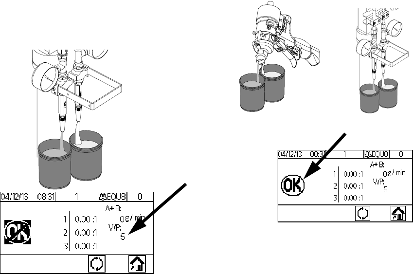
7. Calibration Check Assembly Only: Dispense
material into a waste container at the calibration
check assembly to verify the V/P shown on the DM
is at the correct value.
NOTE: A restrictor pin for the catalyst (B) restrictor
housing may be required to obtain 5 psi (35 kPa,
0.3 bar) or above for the V/P shown on the DM.
8. Disengage the trigger lock.
9. Hold a metal part of the gun firmly to a grounded
metal pail. Trigger the gun until the Display Module
shows “OK”.
10. Place two separate containers on two separate
scales and zero the scales. These containers will be
used in step 11.
NOTE: Weight units of the scales are to be set as
grams.

Calibration Check
3A2894F 51
11. Dispense the chemicals into two separate contain-
ers.
MD2: Chemical will be dispensed through the appli-
cator.
Ultra-lite: Chemical will be dispensed through the
calibration check assembly.
12. Continue to dispense the chemical into the contain-
ers until a 400 gram shot has been dispensed.
NOTE: A value will be shown on the DM when a dis-
pense is complete. This is the value the machine was
running at based on the flow meter values.
13. Weigh both containers separately and calculate the
ratio (A/B) of the two chemicals.
14. Compare the ratio calculated from the weighed con-
tainers with the ratio shown on the DM.
15. If the ratio comparison is acceptable, acti-
vate on the DM or repeat steps 10 through 14
twice if more verification is required. Press to
clear all values if more than three samples are
required.
16. If the ratio comparison is unacceptable, perform
Calibrate the machine. page 38.
Maintenance
52 3A2894F
Maintenance
Adjust Packing Nuts
NOTE: There must be no pressure when adjusting the
packing nuts. Air pressure in the feed tanks is too much.
1. Follow Pressure Relief Procedure, page 46,
including relieving air pressure in the tanks.
2. Fill metering pump packing nuts with throat seal liq-
uid (TSL).
3. After TSL is added, torque metering pump packing
nuts to 50 ft-lb (67.5 N•m). Follow instructions in
Xtreme Lowers manual 311762.
4. Fill dosing valve packing nut with throat seal liquid
(TSL).
5. After TSL is added, tighten dosing valve packing
nuts 1/4 turn after nut contacts packings; about
145-155 in-lb (16-18 N•m).
Filters
Once a week check, clean, and replace (if needed) the
following filters.
•S100 and U100 Models:
Catalyst pump outlet filter comes with a 60 mesh fil-
ter. Two pack 60 mesh filter replacement kit,
224459, is available.
•P100 Models:
Catalyst pump outlet filter comes with a 30 mesh fil-
ter. Two pack 30 mesh filter replacement kit,
224458, is available.
Seals
Once a week, check and tighten throat seals on the
pumps and dosing valve.
Task Schedule
Refer to specific component man-
ual for more detailed information. As Required
Check catalyst (B) filter assembly
to prevent crystallization. Weekly
Verify calibration check assembly
outlets are clear and unob-
structed.
Weekly
Check desiccant. Weekly
Check restrictor housing and pin
assembly to prevent crystalliza-
tion.
Weekly
U100: Check iso lube bottle for
discoloration. Daily
Perform Shutdown and install
nightcap. Daily
Adjust packing nuts. When TSL has
seeped through
the packing nut
TSL
Maintenance
3A2894F 53
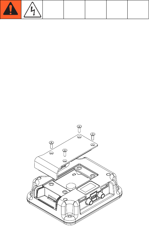
DM - Battery Replacement and Screen Cleaning
Battery Replacement
A lithium battery maintains the DM clock when power is
not connected.
To replace the battery:
1. Disconnect power to the DM.
NOTE: This can be done by removing the CAN cable
from the bottom of the DM.
2. Remove rear access panel.
3. Remove the old battery and replace with a new
CR2032 battery.
4. Properly dispose the old lithium battery according to
local codes.
5. Replace rear access panel.
6. Connect the power to the DM and reset the clock
through Screen 3. Refer to Appendix B - DM
Setup Screens Overview for more detail.
Cleaning
Use any alcohol-based household cleaner, such as
glass cleaner, to clean the DM. Spray on the rag then
wipe DM. Do not directly spray the DM. Replaceable
screen protectors, 15M483, are available.
Maintenance
54 3A2894F
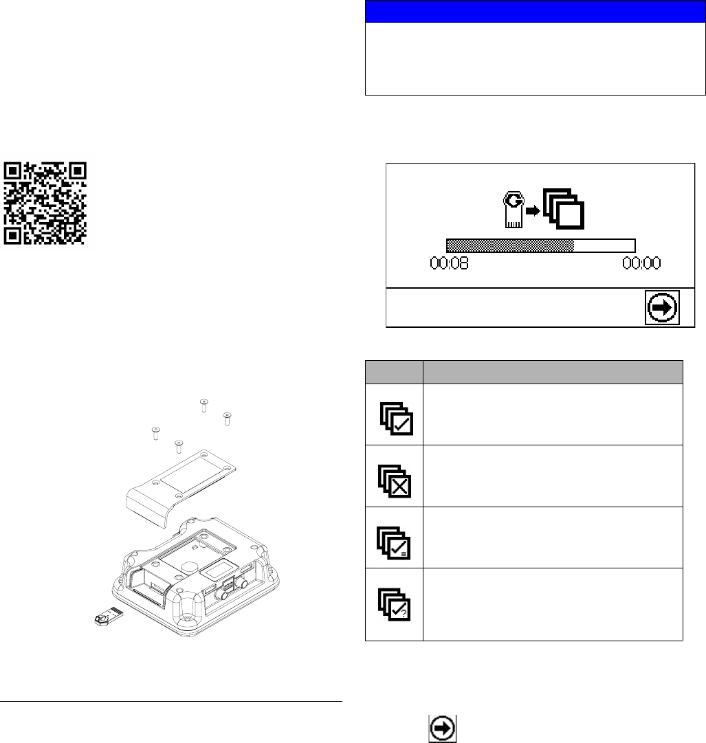
Software Update Procedure
When software is updated on the DM, the software is
then automatically updated on all connected GCA com-
ponents. A status screen is shown while the software is
updating to indicate the progress.
Refer to PKE 2823 found at
http://graco.custhelp.com/app/answers/detail/a_id/2823/
or by utilizing the QR code below for software version
history.
1. Turn the power switch to OFF.
2. Remove the DM from the bracket.
3. Remove the token access panel.
4. Insert and press software upgrade token (Token
part no.16V853) firmly into the slot.
5. Install the DM onto the bracket.
6. Turn the power switch to ON.
NOTE: When the screen turns on, the following screen
will appear.
7. Remove the token.
8. Replace the token access panel.
9. Press to continue.
FIG. 12: Remove Access Cover
NOTICE
A status is shown while software is updating to indi-
cate progress. To prevent corrupting the software
load, do not remove token until the status screen dis-
appears.
Icon Description
Update successful.
Update unsuccessful.
Update complete, no changes necessary
Update was successful/complete but one
or more GCA modules did not have a
CAN boot-loader, so the software was not
updated in that module.
Troubleshooting
3A2894F 55
Troubleshooting
1. Follow Pressure Relief Procedure, page 46, before checking or repairing a dispense valve.
2. Check all possible problems and causes before disassembling the dispense valve.
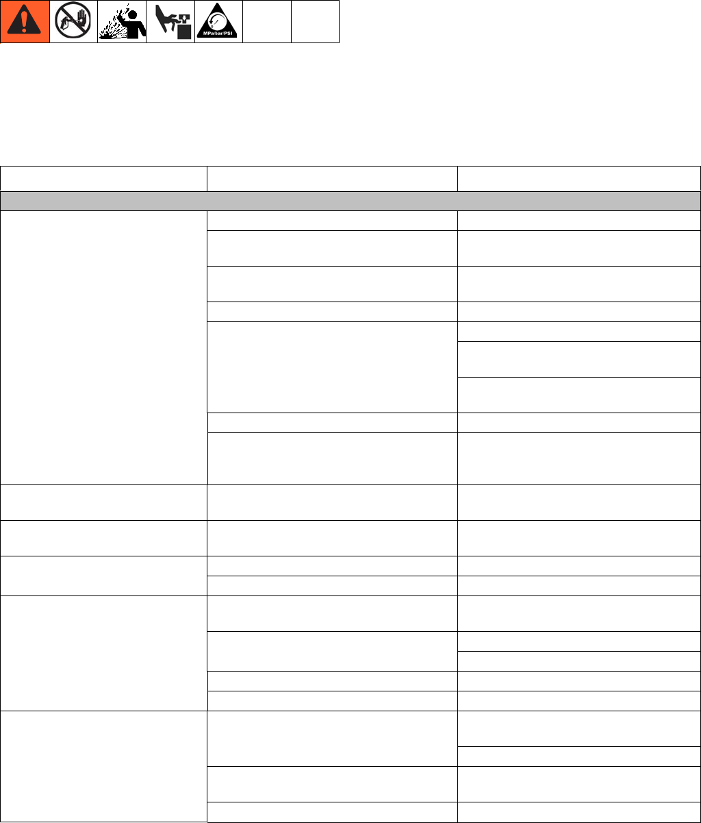
Mechanical and Electrical
PROBLEM CAUSE SOLUTION
Dispense Applicator
No flow of catalyst (B). Clogged gun nose. Clean or replace the gun nose.
Clogged injector housing (Ultra-lite
only). Clean or replace the injector housing.
Clogged restrictor housing Clean or replace the restrictor housing
and pin.
Ball valve is closed. Open the ball valve.
V/P is off. Ensure the power is on.
Ensure the machine is in dispense
mode.
Ensure V/P is turned on when machine
enters Purge/Prime mode.
No air to catalyst (B) pump. Turn air on.
No catalyst ram down pressure.
Ensure that there is pressure to the
catalyst ram and that the control lever
is in the down position.
Dosing valve leaking at rod. Loose or worn packings. Tighten packing nut. If leak continues,
replace the packings.
Dosing valve between main
housing and outlet housing. Bad o-ring. Replace both o-rings on the seat.
Dosing valve not cycling Bad cable. Replace the cable.
Bad power valve. Replace the power valve.
Dispense valve will not dispense
material. Trigger lock engaged. Disengage the trigger lock.
No air to MD2. Connect air to the MD2.
Turn on the air.
Clogged mixer. Clean or replace Tri-core or Flex mixer.
Ultra-lite has cured material in it. Clean or replace.
Dispense valve will not stop
material dispense. No air to MD2. Connect air to the MD2.
Turn on the air.
Bad seal in MD2. Repair the MD2. Refer to the MD2 for
more details
Ultra-lite seal is worn Replace the seal.
Troubleshooting
56 3A2894F
No material flow. Material supply is off. Ensure the base (A) solenoid valve is
on and has pressure.
Ensure the catalyst (B) V/P is on and
has pressure.
Ensure the motor(s) have air pressure.
Ensure there is sufficient down pres-
sure and the control lever is in the
down position.
Clogged mixer. Replace the static mixer.
Clean or replace the Tri-core or hose
mixer.
Clogged restrictor Clean or replace the restrictor.
Fluid Plate
V/P won't turn on.
NOTE: The V/P turns off after 30
seconds of no activity. It will turn
on during dispense or when
entering Purge/Prime mode.
Bad cable. Replace the cable.
Disconnected cable. Connect the cable.
V/P reads “0”. Air supply to V/P shut off. Turn on the air supply to the V/P.
V/P does not match information
on the information screen. Air supply is restricted. Replace with a minimum 3/4 in. ID
hose.
Faulty V/P. Replace V/P
V/P obtains 85 psi (586 kPa,
5.86 bar) and then alarms. Flow rate is too high. Reduce the flow rate.
Too much restriction in the catalyst (B)
hose. Resize the hoses to reduce restriction.
Flowmeter clogged. Clean or replace the flow meter.
Bad flowmeter. Replace the flowmeter.
Catalyst (B) air motor pressure is too
low.
Catalyst (B) air motor pressure is too
low.
Clogged restrictor housing. Clean or replace restrictor housing and
pin.
Abnormal pressures during oper-
ation or after dispense Pressures not balanced. Change catalyst hose size.
Ball/seat not seating properly in fluid
regulator(s). Clean or replace ball/seat.
Restrictor pin not seating in housing.
Use a fitting behind the restrictor hous-
ing with an inner diameter that will not
allow the pin to back out.
PROBLEM CAUSE SOLUTION

Troubleshooting
3A2894F 57
Pump
Abnormal pump pressures dur-
ing operation. Worn or damaged packings. Replace the packings.
Bad check valves. Clean or replace the check valves.
Pump moves during stall. Malfunctioning check valves. Clean or replace the check valves.
Pump does not run. No air supply to the pump. Turn on the air or increase the air pres-
sure.
Catalyst (B) ball valve is closed. Open the ball valve.
Clogged mixer. Replace or clean the mixer.
Ultra-lite has cured material in it. Clean or replace.
Clogged restrictor Clean or replace the restrictor.
PROBLEM CAUSE SOLUTION

Troubleshooting
58 3A2894F
Display Module
CODE PROBLEM CAUSE SOLUTION
F6A3-A Base Flow Meter Error Flow meter signal is not detected. Check the base flow-meter cable.
Flow meter is clogged. Replace sensor.
Flow rate is too low. Clean the flow meter.
F6B3-A Catalyst Flow Meter Error Flow meter signal is not detected. Check the catalyst flow-meter cable.
Flow meter is clogged. Replace sensor.
Flow rate is too low. Clean out the flow meter.
Increase system flow rate.
F5D0-A Machine not calibrated Calibration sequence has not been
performed.
Perform Calibration procedure or
enter known calibration values.
F9D4-A System Flow Rate too Low Flow rate is too low for accurate
measurement by flow meters. Increase the system flow rate.
Reduce the restriction in the catalyst
flow path.
F9D5-A System Flow Rate too High Flow rate is too high for accurate
measurement. Decrease the system flow rate.
Increase the restriction in the cata-
lyst flow path.
R4D0-A High Ratio Alarm Ratio is too high. Re-calibrate the machine.
Catalyst material line is plugged. Check the material supply.
The flow for the base is too high
and the flow for the catalyst is too
low.
The flow could be turned down or a
larger size hose could be used for
the catalyst.
Adjusted flowrate between dis-
penses.
Run until machine status states
“OK.”
R1D0-A Low Ratio Alarm Ratio is too low. Re-calibrate the machine.
Base flow rate is too low. Check the material supply.
Adjusted flowrate between dis-
penses. Increase the base flow rate.
Run until machine status states
“OK.”
R9CX-A Insufficient Restrictions /
Unbalanced Pressure
The restrictor pin is missing or
under sized.
Install a restrictor pin of the correct
size.
Hoses are not sized to properly
balance the pressures.
Size the hoses so that the pressures
are balanced.
L1C1-D Check Pump Base/Cata-
lyst Drum Low level drum. Check drum base or catalyst mate-
rial level and replace if necessary.
Check the drum level sensor cable.
N/A Purge Timer Expired Gel timer has expired. Use machine. (Normal operation).
Dispense material into a waste con-
tainer.
Base purge the machine.

Troubleshooting
3A2894F 59
CUCX-V Duplicate Node Found Unknown Software Error. Cycle the system power.
Unintended module plugged into
the system.
Verify that only necessary GCA mod-
ules are plugged into system.
CACX-A FCM Missing FCM unplugged from CAN bus. Verify the FCM CAN cable is
plugged in.
Damaged FCM. Replace the FCM.
Damaged FCM Base. Replace the FCM base.
CAUX-A USB Disconnected USB unplugged from CAN bus. Verify the USB CAN cable is plugged
in.
Damaged USB. Replace the USB.
Damaged USB Base. Replace the USB base.
CODE PROBLEM CAUSE SOLUTION
Accessories and Kits
60 3A2894F
Accessories and Kits
Light Tower 24R824
Visual and audible indicator of machine status.
Low Level Sensors, 24R935
(S100 and P100 only)
Alerts the user when material drums are empty.
Calibration Check Assembly,
24R777
Allows the user to watch the DM while performing the
Calibration Check procedure. Kit is required for all
Ultra-lite dispense valve applications.
Status Description
Red - Solid An error has occurred and
requires maintenance.
Red and Green - Solid Allows a dispense but notifies
the user of an uncleared error
(e.g. low level).
Green - Solid Machine is ready to dispense
Green - Flashing Machine is okay. Gel timer
has expired.
Accessories and Kits
3A2894F 61
USB Kit, 24R936
Allows the user to monitor and download information of
the machine status.
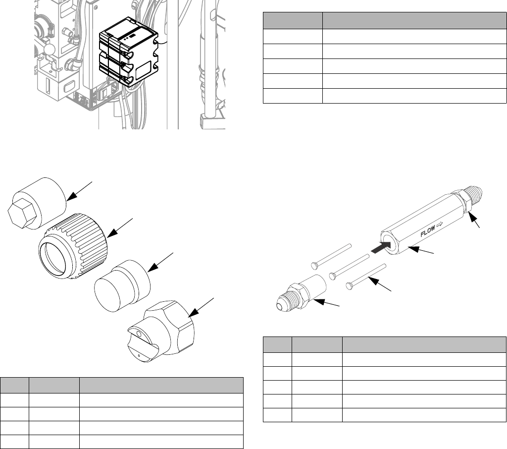
MD2 Nose Pieces
Catalyst (B) Hoses
Allows the user to balance material pressure in the cata-
lyst (B) line by changing the hose diameter.
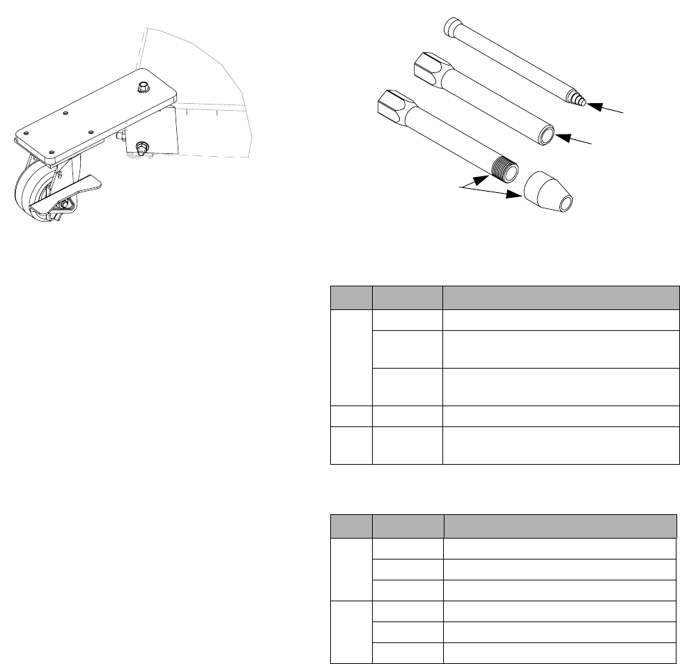
Restrictor Kit, 24R804
Allows the user to balance material pressure in the cata-
lyst (B) line by changing the pin size.
Ref Part Description
201 15V628 10:1 Nightcap
202 15K688 Retaining Nut
203 24P850 10:1 Ratio Check
204 256793 Assembly Tool
203
201
202
204
Part Description
16W047 HOSE, assy, 3/32”x60”, 6k, nylon
16V531 HOSE, assy, 1/8”x60”, 6k, nylon
16V219 HOSE, assy, 1/4”x60”, 5k, ss, braid
16V220 HOSE, assy, 3/8”x60”, 5k, ss, braid
16V221 HOSE, assy, 1/2”x60”, 5k, ss, braid
Ref Part Description
101 16V360 HOUSING, restrictor, 1/4npt
102 16V356 PIN, restrictor, #1, 0.094 in.
103 16V359 PIN, restrictor, #2, 0.098 in.
104 16V357 PIN, restrictor, #3, 0.102 in.
105 124961 FITTING, 04jic x 1/4npt
101
102,
103,
104
105
105
Accessories and Kits
62 3A2894F
Caster Kit, 24T091
Includes four casters.
Mixer Elements for MD2
10 mm Mixer Elements
1/2 in. Mixer Elements
Ref Part Description
001 127160 MIXER, assy, 10mm x 12 element
24T250 MIXER, assy, 10mm x 12 element -
25 count
24T251 MIXER, assy, 10mm x 12 element -
50 count
002 16V841 SLEEVE, mixer, no front thread
003 24T035 SLEEVE, mixer, thread x 1/4 NPT
outlet
Ref Part Description
001 512288 MIXER, assy, 1/2 x 24 element
512289 MIXER, assy, 1/2 x 30 element
512286 MIXER, assy, 1/2 x 36 element
002 16T001 SLEEVE, mixer, 24 element
16T002 SLEEVE, mixer, 30 element
16T003 SLEEVE, mixer, 36 element
001
002
003

Accessories and Kits
3A2894F 63
Appendix A - DM Icons Overview
64 3A2894F
Appendix A - DM Icons Overview
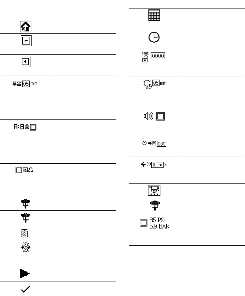
Setup Screen Icons
Icon Description
Return to Home Screen
Left Navigation
Navigates to the previous
screen.
Right Navigation
Navigates to the next
screen.
Set Purge Timer
Allow the machine to
remind the operator to take
a shot before the chemical
hardens in the gun. Timer
starts once a dispense is
complete.
Lock Ratio Setpoint
Lock the current ratio set-
point. Ratio setpoint will not
be able to be adjusted
when activated. Icon shown
represents that it is not
locked.
Low Level Sensor Option
Toggle if a low level sensor
is installed or not installed
on the machine. Icon shown
represents not installed.
Base (A) Pump
Catalyst (B) Pump
Weight
System units are in grams
Flow Meter
Shows the calibration fac-
tor (K) after calibration has
been performed.
Start Calibration
Confirmation
Calendar / Date
Set the date format and cur-
rent date.
Time
Set the current time in 24
hour format.
Password
Set a password to lock sys-
tem settings. Password
“0000” disables the lock.
Backlight Time
Set how long the screen will
illuminate when idle before
darkening. Entering “0” dis-
ables the timer.
Audible Alarm
Allow the machine to sound
an alarm when an error
occurs.
Download Depth
Set how many hours of data
the system will download.
Log Intervals
Set the time interval that the
system will record the
machine status.
Display Module
Advanced Fluid Control
Module
Ultra-Lite Tri-core Mixer
(P100 Model Only)
Toggle if an ultra-lite tri-core
mixer is installed on a P100
machine.
Icon Description
Appendix A - DM Icons Overview
3A2894F 65
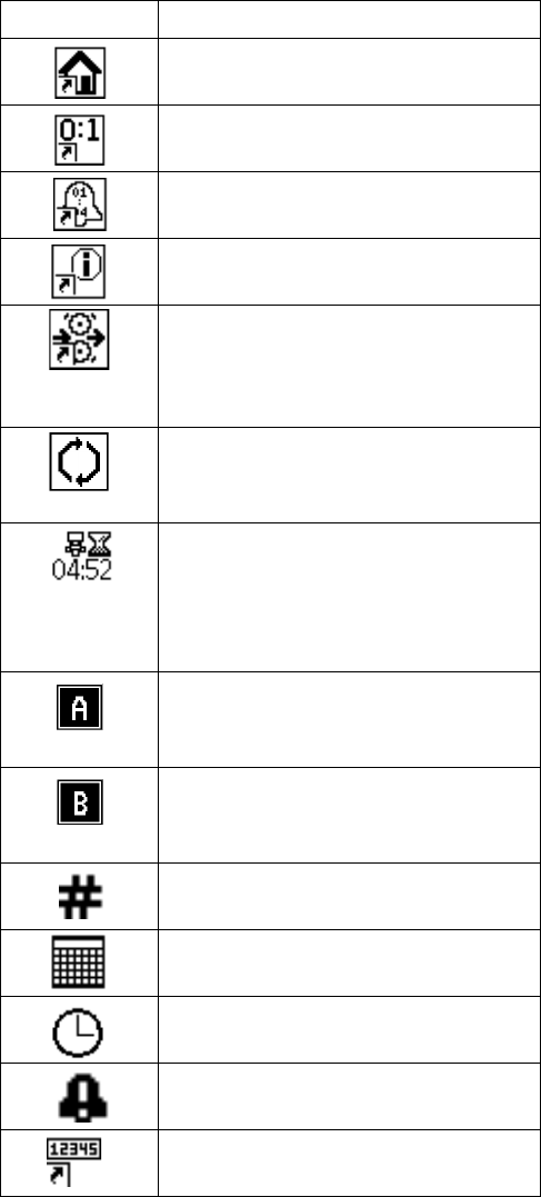
Run Screen Icons
Icon Description
Return to Home Screen
Navigate to Purge/Prime Screen
Navigate to Alarm Log Screen
Navigate to Information Screen
Calibration Check
Changes the machine status to not
okay in order to perform the calibra-
tion check procedure.
Calibration Reset
Clears all data and resets all sam-
ples to “0”.
Purge Timer Counter
Visual indicator to show the user the
remaining idle time before another
shot needs to be taken. The timer
will begin to flash when expired.
Base (A) Pump Select
Icon will appear white when not acti-
vated, black when activated.
Catalyst (B) Pump Select
Icon will appear white when not acti-
vated, black when activated.
Error Number / Event Number
Date
Time
Error / Event Code
Navigate to Totalizer Screen
Appendix B - DM Setup Screens Overview
66 3A2894F
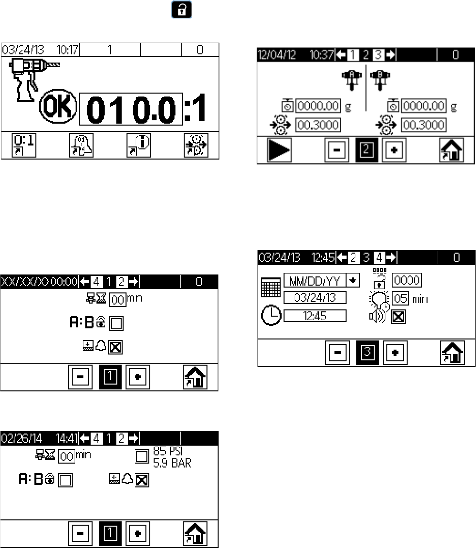
Appendix B - DM Setup Screens Overview
If the DM is showing a Run screen, press to
access the Setup screens, which have a black header.
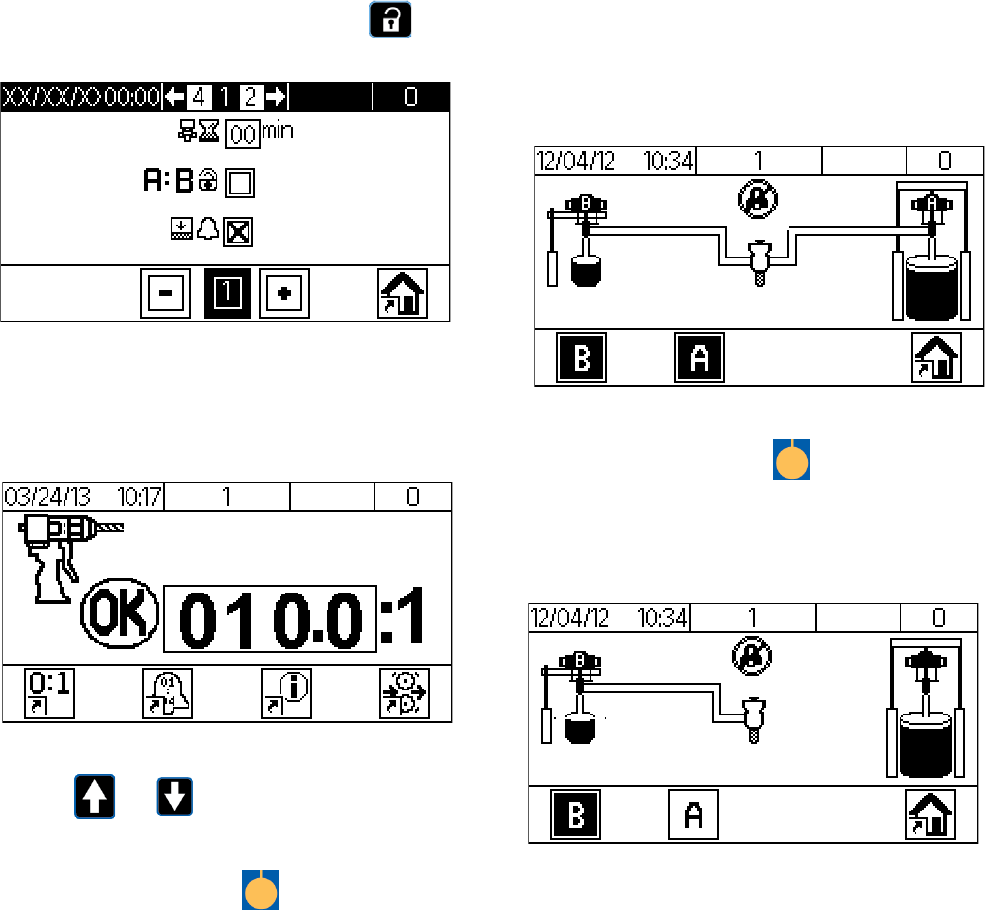
Screen 1
This screen allows the user to set the purge timer, lock
the ratio setpoint, toggle if low level sensors are
installed, and to toggle if an Ultra-lite with Tri-core mixer
is installed on a P100 machine.
Screen 2
This screen allows the user to calibrate the machine.
See Calibrate the machine. page 38, for more details.
Screen 3
This screen allows the user to format and set the current
date and time, reset the password, adjust the backlight
timer, and toggle sound/silent operation.
S100 and U100 Models
P100 Models
Appendix B - DM Setup Screens Overview
3A2894F 67
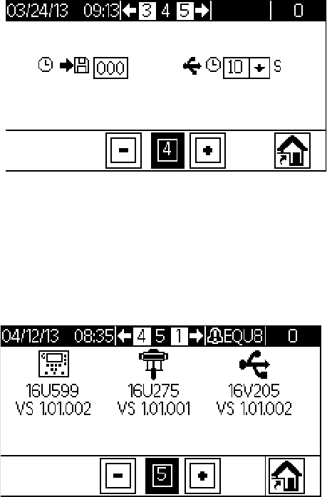
Screen 4
This screen is only displayed when the USB option is
installed. The screen allows the user to enable down-
loading of USB logs, set log intervals, and set how many
hours of data to download.
Screen 5
This screen is displayed as Screen 4 when the USB
option is not installed. The screen displays information
of part numbers and software versions that are currently
found within the system. The USB information is only
displayed when the USB option is installed.
Appendix C - DM Run Screens Overview
68 3A2894F
Appendix C - DM Run Screens Overview
If the DM is showing a Setup screen, press to
access the Run screens.
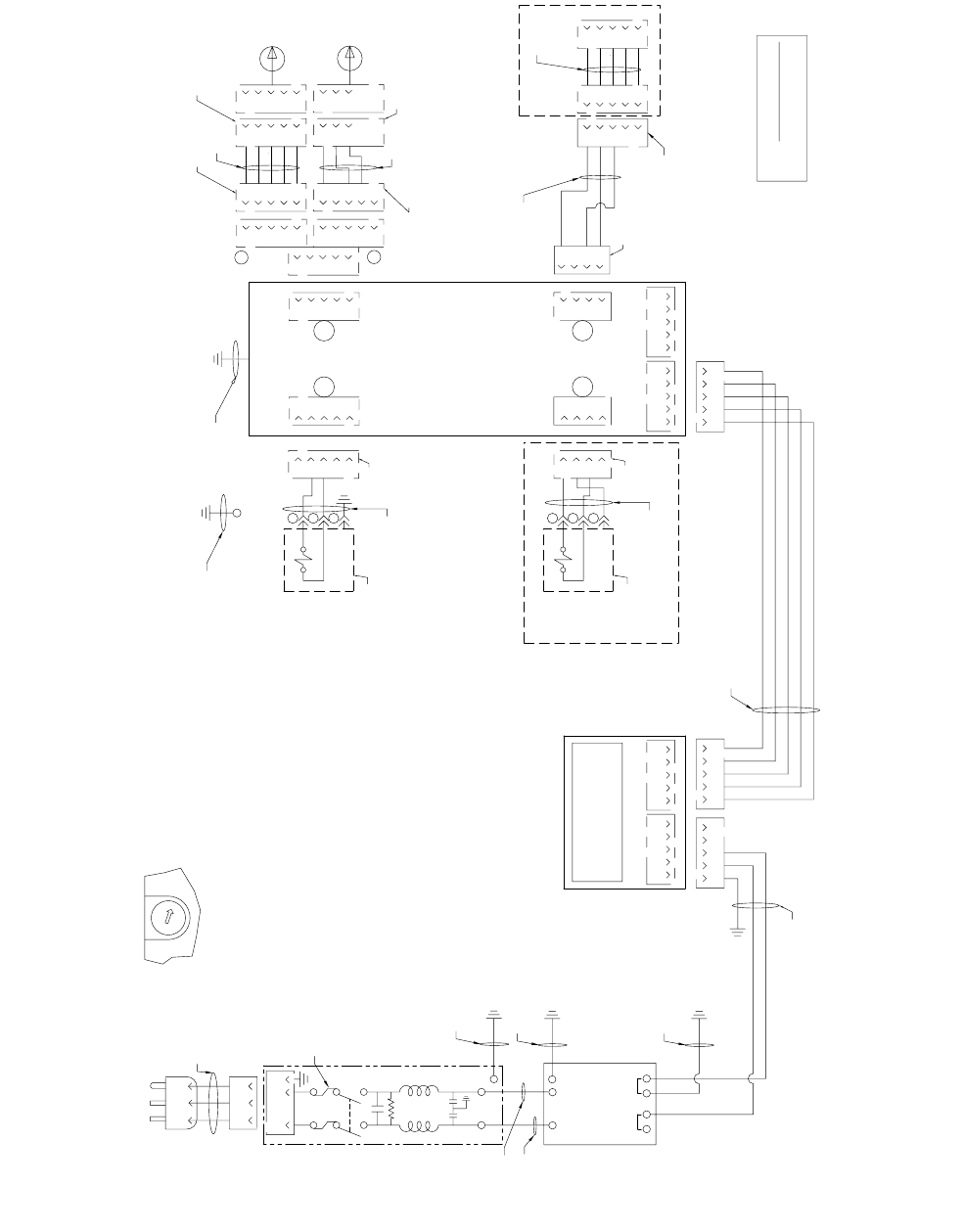
Home
This screen shows the current ratio and allows the user
to access other screens.
• Press or to increase or decrease the
ratio.
• Press the corresponding to access another
screen or to toggle an option.
• Shows the current state of the machine (okay/not
okay).
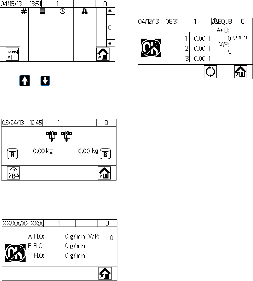
Purge/Prime
This screen allows the pumps to be run independently.
NOTE: All machine alarms are disabled when this
screen is displayed on the DM.
• Press the corresponding to deactivate or acti-
vate the desired pump for operation.
NOTE: The screen below shows only the catalyst (B)
pump selected.
Appendix C - DM Run Screens Overview
3A2894F 69
Alarm Log
This screen displays the last 70 errors that have
occurred.
• Press or to show other errors.
Totalizer
This screen displays the total amount of material (in kilo-
grams) dispensed for each pump.
Information
This screen displays diagnostic information useful in
troubleshooting.
Calibration Check
This screen displays the ratio after a calibration check
dispense.
NOTE: Production material cannot be dispensed
from this screen.

Appendix D - DM Error Codes
70 3A2894F
Appendix D - DM Error Codes
Error Code Error Name Error Type
0000-0 No Active Errors Alarm
CA00-A Unrecognized Error Alarm
F6A3-A Pump A Check Flow Meter Alarm
F6B3-A Pump B Check Flow Meter Alarm
F5D0-A Machine has not been calibrated Alarm
F9D4-A System Flow Rate is too Low Alarm
F9D5-A System Flow Rate is too High Alarm
R4D0-A High Ratio Alarm Alarm
R1D0-A Low Ratio Alarm Alarm
L1C1-D Check Pump A Drum Deviation
EHD0-R Purge Timer Expired Record Only
E9D0-R System not ok for dispense Record Only
ELM0-R System Power On Record Only
EMM0-R System Power Off Record Only
ENB6-R Begin Flowmeter Calibration, Pump A Record Only
ENA6-R Begin Flowmeter Calibration, Pump B Record Only
ENB7-R End Flowmeter Calibration, Pump A Record Only
ENA7-R End Flowmeter Calibration, Pump B Record Only
ENB8-R Abort Flowmeter Calibration, Pump A Record Only
ENA8-R Abort Flowmeter Calibration, Pump B Record Only
EGC6-R Enter Purge/Prime Screen Record Only
EGB9-R Purge On, Pump A Record Only
EGBA-R Purge Off, Pump A Record Only
EGA9-R Purge On, Pump B Record Only
EGAA-R Purge Off, Pump B Record Only
EGC7-R Exit Purge/Prime Screen Record Only
ECCX-R Ratio Changed Record Only
EADX-R Start Dispense Record Only
EBDX-R End Dispense Record Only
CUCX-V Duplicate Node Found Advisory
CACX-A FCM Missing Alarm
CAUX-A USB Disconnected Alarm
ECB3-R Pump A K-factor Changed Record Only
ECA3-R Pump B k-factor Changed Record Only
ECDC-R Gel Timer Changed Record Only
ECFB-R Pressure Transducer Installed Record Only
EQU0-R USB Logs Downloaded Record Only
EQU0-D No Configuration Deviation
EQU8-D Disk Removed Too Early Deviation
R9CX-A Insufficient Restriction / Unbalanced Pressures Alarm

Appendix D - DM Error Codes
3A2894F 71
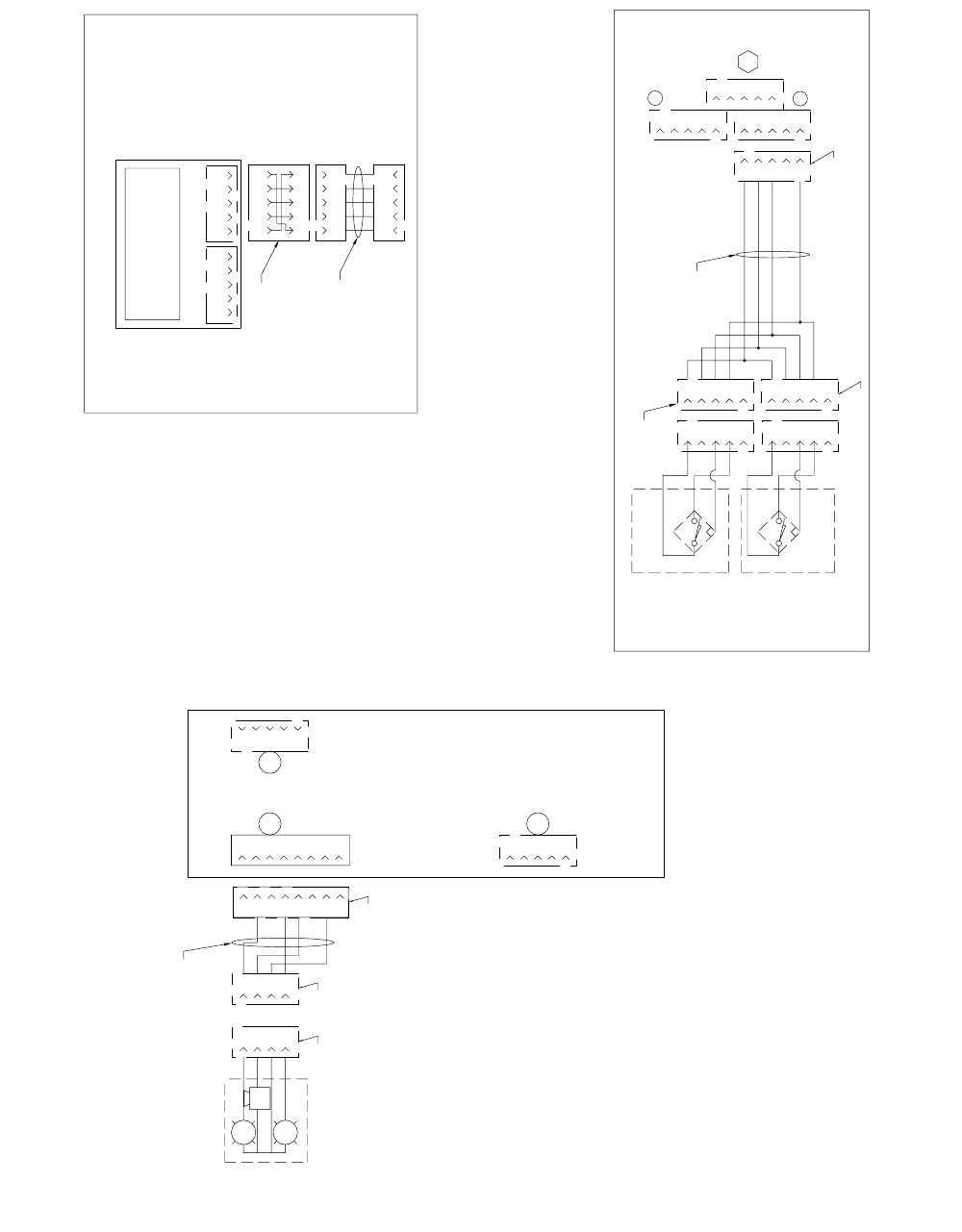
Schematics
72 3A2894F
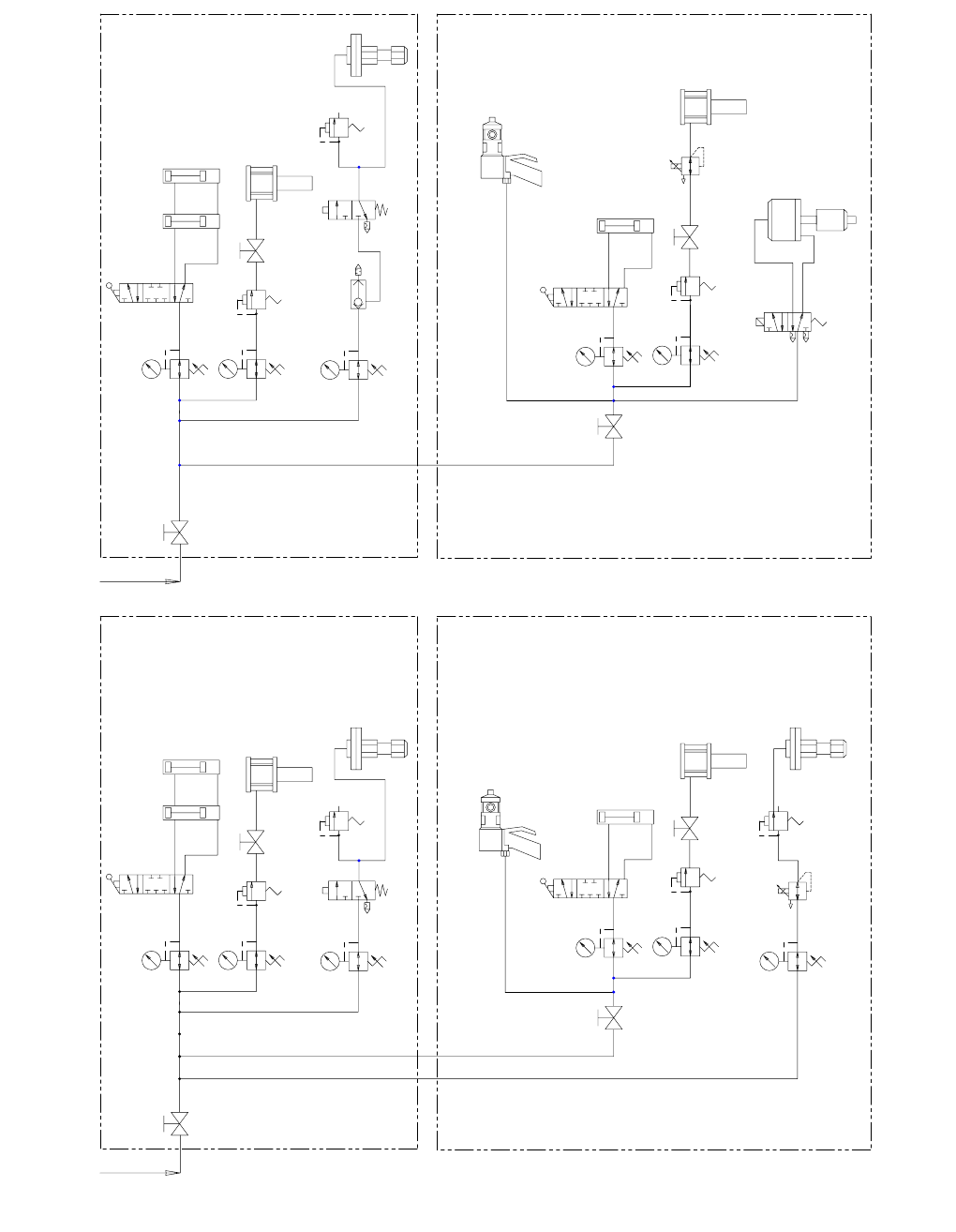
Schematics
140
149
147
145
142
110
138
136
134
132
130
128
126
124
122
120
118
114
116
112
108
106
104
102
100
141
148
144
146
143
111
139
137
135
133
131
129
127
125
123
121
119
115
117
113
109
107
105
103
101
150
155
152
151
154
153
159
157
158
156
160
165
162
161
164
163
HARNESS
16U012
2.5M
120V/240V INPUT PS148
126453
LNGRD
V-
V+
24VDC OUTPUT
M12 5 PIN
CAN CABLE
BLK
M12 5 PIN
FEMALE
120952
4M
RED
160
161
V-
V+
FLUID CONTROL
MODULE FRONT VIEW
FCM232
M8 4 PIN
FEMALE
M12 5 PIN
FEMALE
M12 5 PIN
FEMALE
M8 4 PIN
FEMALE
CAN COM 1 CAN COM 2
TO GROUND LUG
HARNESS
16U132
SPL335
126520
HV FLOWMETER
246652
HARNESS
122030
.5M
LV FLOWMETER
289814
HARNESS
16U014
.5M
BLK
HARNESS
126996
0.5M
LABEL
EP370
LABEL J4
LABEL J2A
LABEL J2A
LABEL J2B
LABEL J2B
M8 4 PIN
MALE
SOL
1
2
3
HARNESS
123395
1.5M
DV320
HV AIR DUMP
127032
LABEL SOL410 LABEL J1
N
L
GND
N
L
GND
CORDSET
121598
(USA)
L
N
GND
SW125
120910
FUSES
4A
114835
50-60HZ
1PH/
220V/
TO GROUND
LUG
TO GROUND
LUG
CAN COM 1 CAN COM 2
DISPLAY MODULE
24F493
M12 5 PIN
FEMALE
HARNESS
16V097
HARNESS
16V096
HARNESS
16V094
HARNESS
16V094
ON FLUID PLATE
135
136
TO GROUND LUG
HARNESS
16V151
ON RAM BOX
TO GROUND LUG
ON FLUID PLATE
FCM SELECTOR SWITCH
1
FOR SILICONE MACHINES: 24R809 AND 24R810 SET DIAL TO "1"
FOR POLYURETHANE MACHINES: 24R811 AND 24R812 SET DIAL TO "2"
FOR POLYSULFIDE MACHINES: 24R815 AND 24R816 SET DIAL TO "3"
TO GROUND
LUG
HARNESS
16V096
CHANGING THIS DOCUMENT MAY AFFECT
AGENCY APPROVAL AND/OR TECHNICAL FILE
SEE GRACO ENGINEERING STD. 2.7001
AGENCY: CE,ETL
COMPLIANCE DOCUMENT
SOL
1
2
3
HARNESS
127399
4.5M
PWR VALVE
127356
LABEL SOLXM LABEL J3
M8 4 PIN
MALE
M12 5 PIN
MALE
POLYSULFIDE OPTION
HARNESS
123657
4M
M12 5 PIN
FEMALE
M12 5 PIN
MALE
M12 5 PIN
FEMALE
POLYSULFIDE OPTION
4
3
2
1
4
3
2
1
5
5
4
3
2
1
4
3
2
1
43215 43215
43215 43215
4
3
2
1
5
4
3
2
1
5
4
3
2
1
5
1
2
3
2
1
4
3
2
1
5
4
3
2
1
5
C
B
A
4
3
2
1
5
3
2
1
4
5
4
2
3
1
5
4
2
3
1
4
3
2
1
5
43215 43215
43215
4
3
2
1
4
3
2
1
5
4
3
2
1
5
1 1
1 1
Schematics
3A2894F 73
210
234
232
230
228
226
224
222
220
218
214
216
212
208
206
204
202
200
211
235
233
231
229
227
225
223
221
219
215
217
213
209
207
205
203
201
256
254
252
250
248
246
244
242
240
236
238
257
255
253
251
249
247
245
243
241
237
239
264
262
260
258
265
263
261
259
OPTIONAL
LOW LEVEL
SENSOR
24R935 M12 5 PIN
MALE
PX353
LOW LEVEL
DRUM SENSOR
HV RAM
FLUID CONTROL
MODULE BACK VIEW
M12 5 PIN
FEMALE
M12 8 PIN
FEMALE
M12 5 PIN
FEMALE
PX353
LOW LEVEL
DRUM SENSOR
LV RAM
HARNESS
127137
LABEL J1B
LABEL J1BB
LABEL J1BA SPL335
126520
TO J1
M12 4 PIN
MALE
LIGHT TREE
24R824
G
R
M12 4 PIN
FEMALE
M12 8 PIN
MALE
J5
HARNESS
127184
0.5M
J5 J5
OPTIONAL
USB ADAPTER
24R936
CAN COM 1 CAN COM 2
USB MODULE
289900
M12 5 PIN
FEMALE
HARNESS
120952
M12 5 PIN
FEMALE
ADAPTER
16T072
A
4
3
2
1
3
4
1
2
5
5
4
3
2
1
5
4
3
2
1
8
7
6
5
2
4
3
1
5
4
3
2
1
5
4
3
2
1
5
4
3
2
1
5
4
3
2
1
5
4
3
2
1
5
1
2
4
3
2
1
5
4
3
2
1
4
3
2
1
4
3
2
1
43215 43215
43215
43215
43215
43215
8
7
6
5
1 1
1
118
Schematics
74 3A2894F
340
349
347
345
342
310
338
336
334
332
330
328
326
324
322
320
318
314
316
312
308
306
304
302
300
341
348
344
346
343
311
339
337
335
333
331
329
327
325
323
321
319
315
317
313
309
307
305
303
301
350
351
360
358
356
353
352
359
355
357
354
361
362
369
367
364
363
370
366
368
365
80 PSIG MIN
PLANT AIR
SILICONE MD2 PNUEMATIC GUN
80 PSIG MIN
PLANT AIR
POLYSULFIDE OPTION
HV RAM / PUMP (RED)
HV RAM PRESSURE
LV RAM / PUMP (BLUE)
LV RAM PRESSURE
EP370
HV AIR MOTOR
RAM UP/DOWN
RAM UP/DOWN
MAIN AIR
SHUT-OFF
SOL320
REGULATOR
HV MATERIAL
REGULATOR
AIR MOTOR
SHUT-OFF
ON/OFF
3-WAY VALVE
127032
MAIN AIR
SHUT-OFF
REGULATOR
HV AIR MOTOR
100
100
MD2 PNEUMATIC GUN
HV RAM CYLINDERS
100
LV AIR MOTOR
AIR MOTOR
SHUT-OFF
REGULATOR
LV AIR MOTOR
100
REGULATOR
LV MATERIAL
REGULATOR
E/P
REG VALVE
127029
LV FLUID REGULATOR
100
LV RAM CYLINDER
100 100
(DELETE THIS LINE FOR 6K GUN)
SAFETY VALVE
85 PSI
HV FLUID REGULATOR
SAFETY VALVE
85 PSI
SAFETY VALVE
75 PSI FOR 3000 PSI SYSTEM
90 PSI FOR 4000 PSI SYSTEM
SAFETY VALVE
75 PSI FOR 3000 PSI SYSTEM
90 PSI FOR 4000 PSI SYSTEM
102
103
HV RAM / PUMP (RED)
HV RAM PRESSURE
LV RAM / PUMP (BLUE)
LV RAM PRESSURE
EP370
HV AIR MOTOR
RAM UP/DOWN
RAM UP/DOWN
MAIN AIR
SHUT-OFF
SOL320
REGULATOR
HV MATERIAL
REGULATOR
AIR MOTOR
SHUT-OFF
ON/OFF
3-WAY VALVE
127032
MAIN AIR
SHUT-OFF
REGULATOR
HV AIR MOTOR
100
100
MD2 PNEUMATIC GUN
HV RAM CYLINDERS
100
LV AIR MOTOR
AIR MOTOR
SHUT-OFF
REGULATOR
LV AIR MOTOR
100
E/P
REG VALVE
127396
XM VALVE
LV RAM CYLINDER
100 100
(DELETE THIS LINE FOR 6K GUN)
HV FLUID REGULATOR
SAFETY VALVE
85 PSI
SAFETY VALVE
75 PSI FOR 3000 PSI SYSTEM
90 PSI FOR 4000 PSI SYSTEM
SAFETY VALVE
75 PSI FOR 3000 PSI SYSTEM
90 PSI FOR 4000 PSI SYSTEM
102
QUICK
EXHAUST
127415
OPEN
CLOSED
SOLXM
127356
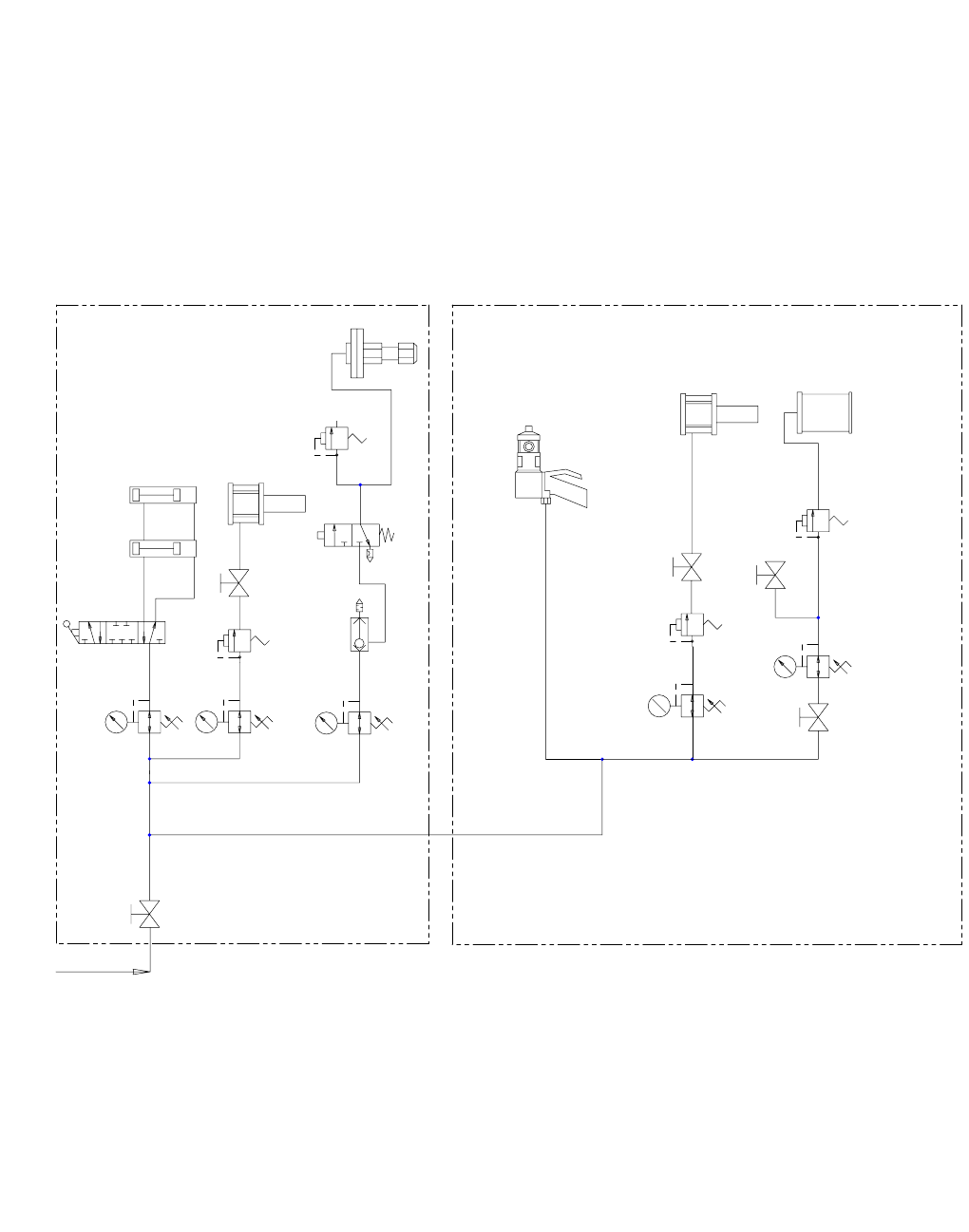
Schematics
3A2894F 75
80 PSIG MIN
PLANT AIR
POLYURETHANE OPTION
440
449
447
445
442
410
438
436
434
432
430
428
426
424
422
420
418
414
416
412
408
406
404
402
400
441
448
444
446
443
411
439
437
435
433
431
429
427
425
423
421
419
415
417
413
409
407
405
403
401
450
451
460
458
456
453
452
459
455
457
454
461
462
469
467
464
463
470
466
468
465
HV RAM / PUMP (RED)
HV RAM PRESSURE
LV RAM / PUMP (BLUE)
HV AIR MOTOR
RAM UP/DOWN
MAIN AIR
SHUT-OFF
SOL320
REGULATOR
HV MATERIAL
REGULATOR
AIR MOTOR
SHUT-OFF
ON/OFF
3-WAY VALVE
127032
REGULATOR
HV AIR MOTOR
100
100
MD2 PNEUMATIC GUN
HV RAM CYLINDERS
100
LV AIR MOTOR
AIR MOTOR
SHUT-OFF
REGULATOR
LV AIR MOTOR
100
100 100
(DELETE THIS LINE FOR 6K GUN)
HV FLUID REGULATOR
SAFETY VALVE
85 PSI
SAFETY VALVE
75 PSI FOR 3000 PSI SYSTEM
90 PSI FOR 4000 PSI SYSTEM
SAFETY VALVE
75 PSI FOR 3000 PSI SYSTEM
90 PSI FOR 4000 PSI SYSTEM
102
103
QUICK
EXHAUST
127415
REGULATOR
LV AIR MOTOR
SAFETY VALVE
100 PSI
104
LV PRESSURE POT
PRESSURE POT
SHUT-OFF
PRESSURE RELIEF
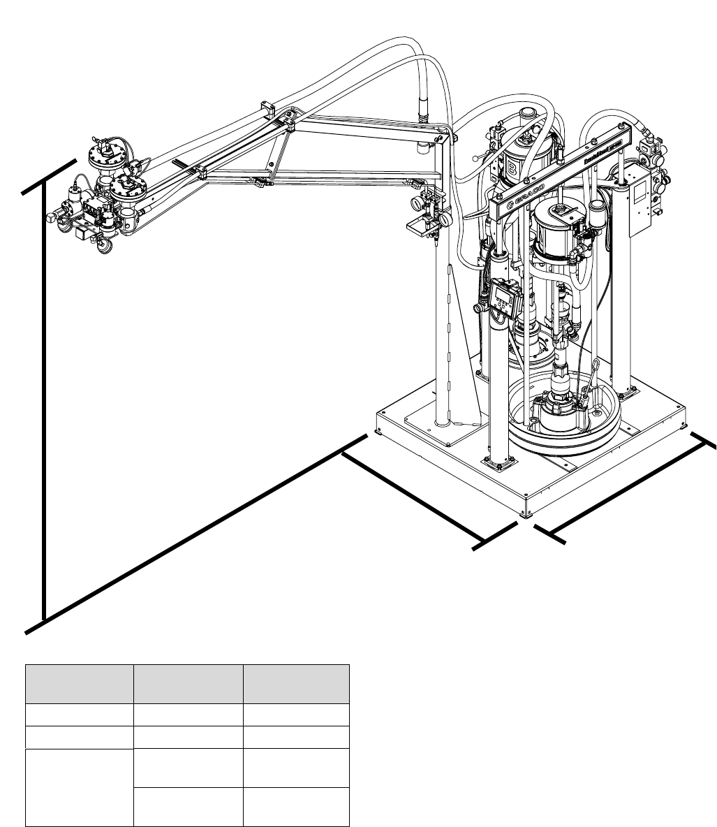
Dimensions
76 3A2894F
Dimensions
AB
C
Dimension
US
(ft)
Metric
(m)
A (Length) 3.3 1.0
B (Width) 3.5 1.1
C (Height) 9.0
(with boom)
2.7
5.3
(without boom)
1.6
S100 Shown
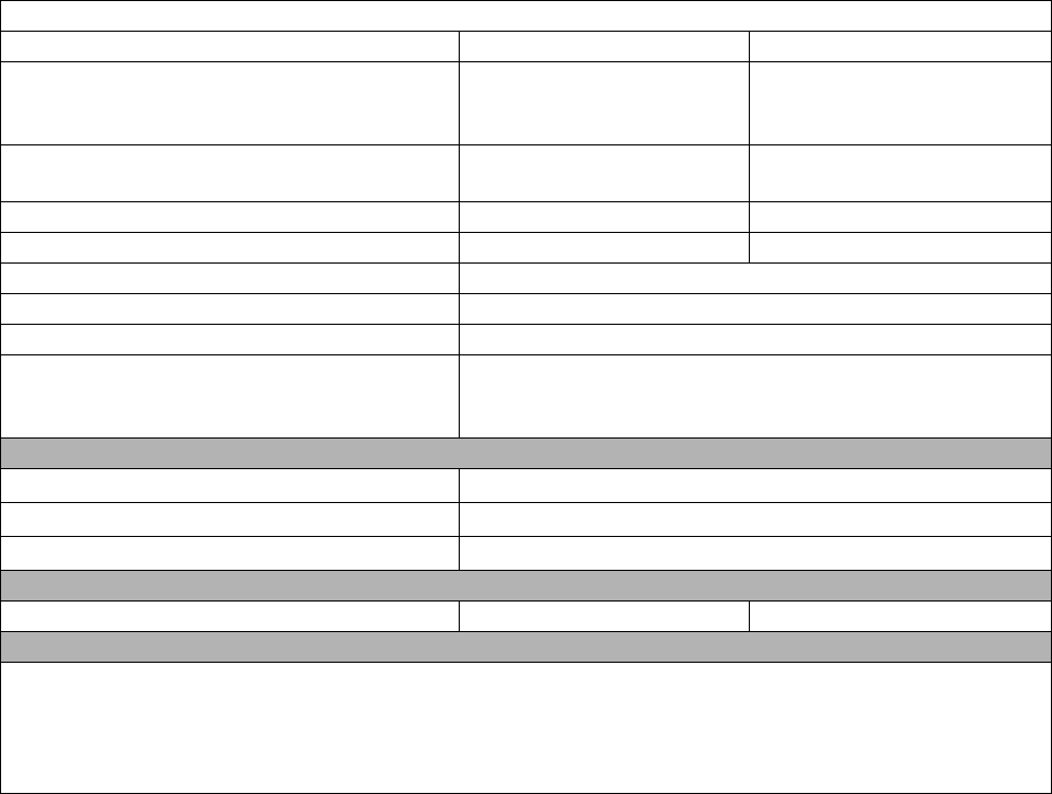
Technical Data
3A2894F 77
Technical Data
ExactaBlend AGP Advanced Glazing Proportioner
US Metric
Maximum fluid working pressure :
MD2 or
Ultra-lite with flexible hose mixer Installed
3000 psi 21 MPa, 207 bar
Maximum fluid working pressure :
Ultra-lite with Tri-core mixer Installed
4000 psi 28 MPa, 276 bar
Incoming Air pressure required* 80-100 psi 0.6-0.7 MPa, 6.0-7.0 bar
Maximum operating temperature 120° F 50° C
Voltage range 90-264 VAC 50/60 Hz 1 phase
Maximum amperage 4
Sound pressure** 82 dB(A)
Wetted parts ★Zinc-plated carbon steel, aluminum ram plate, nitrile rubber
wipers, chrome, stainless steel, UHMW polyethylene, PTFE,
nylon, Buna-N
Inlet/Outlet Sizes
Fluid outlet base 1/2 npt (f)
Fluid outlet catalyst 1/4 npt (f)
Air inlet size 3/4 npt (f)
Weight
All models 865 lb. 392 kg
Notes
*Startup pressures and displacement per cycle may vary based on suction condition, discharge head, air
pressure, and fluid type.
** Sound pressure measured 3.3 feet (1 meter) from equipment.
★Refer to specific component manual for more details.
All written and visual data contained in this document reflects the latest product information available at the time of publication.
Graco reserves the right to make changes at any time without notice.
For patent information, see www.graco.com/patents.
Original instructions. This manual contains English. MM 3A2894
Graco Headquarters: Minneapolis
International Offices: Belgium, China, Japan, Korea
GRACO INC. AND SUBSIDIARIES • P.O. BOX 1441 • MINNEAPOLIS MN 55440-1441 • USA
Copyright 2013, Graco Inc. All Graco manufacturing locations are registered to ISO 9001.
www.graco.com
Revised July 2014
Graco Standard Warranty
Graco warrants all equipment referenced in this document which is manufactured by Graco and bearing its name to be free from defects in
material and workmanship on the date of sale to the original purchaser for use. With the exception of any special, extended, or limited warranty
published by Graco, Graco will, for a period of twelve months from the date of sale, repair or replace any part of the equipment determined by
Graco to be defective. This warranty applies only when the equipment is installed, operated and maintained in accordance with Graco’s written
recommendations.
This warranty does not cover, and Graco shall not be liable for general wear and tear, or any malfunction, damage or wear caused by faulty
installation, misapplication, abrasion, corrosion, inadequate or improper maintenance, negligence, accident, tampering, or substitution of
non-Graco component parts. Nor shall Graco be liable for malfunction, damage or wear caused by the incompatibility of Graco equipment with
structures, accessories, equipment or materials not supplied by Graco, or the improper design, manufacture, installation, operation or
maintenance of structures, accessories, equipment or materials not supplied by Graco.
This warranty is conditioned upon the prepaid return of the equipment claimed to be defective to an authorized Graco distributor for verification of
the claimed defect. If the claimed defect is verified, Graco will repair or replace free of charge any defective parts. The equipment will be returned
to the original purchaser transportation prepaid. If inspection of the equipment does not disclose any defect in material or workmanship, repairs will
be made at a reasonable charge, which charges may include the costs of parts, labor, and transportation.
THIS WARRANTY IS EXCLUSIVE, AND IS IN LIEU OF ANY OTHER WARRANTIES, EXPRESS OR IMPLIED, INCLUDING BUT NOT LIMITED
TO WARRANTY OF MERCHANTABILITY OR WARRANTY OF FITNESS FOR A PARTICULAR PURPOSE.
Graco’s sole obligation and buyer’s sole remedy for any breach of warranty shall be as set forth above. The buyer agrees that no other remedy
(including, but not limited to, incidental or consequential damages for lost profits, lost sales, injury to person or property, or any other incidental or
consequential loss) shall be available. Any action for breach of warranty must be brought within two (2) years of the date of sale.
GRACO MAKES NO WARRANTY, AND DISCLAIMS ALL IMPLIED WARRANTIES OF MERCHANTABILITY AND FITNESS FOR A
PARTICULAR PURPOSE, IN CONNECTION WITH ACCESSORIES, EQUIPMENT, MATERIALS OR COMPONENTS SOLD BUT NOT
MANUFACTURED BY GRACO. These items sold, but not manufactured by Graco (such as electric motors, switches, hose, etc.), are subject to
the warranty, if any, of their manufacturer. Graco will provide purchaser with reasonable assistance in making any claim for breach of these
warranties.
In no event will Graco be liable for indirect, incidental, special or consequential damages resulting from Graco supplying equipment hereunder, or
the furnishing, performance, or use of any products or other goods sold hereto, whether due to a breach of contract, breach of warranty, the
negligence of Graco, or otherwise.
FOR GRACO CANADA CUSTOMERS
The Parties acknowledge that they have required that the present document, as well as all documents, notices and legal proceedings entered into,
given or instituted pursuant hereto or relating directly or indirectly hereto, be drawn up in English. Les parties reconnaissent avoir convenu que la
rédaction du présente document sera en Anglais, ainsi que tous documents, avis et procédures judiciaires exécutés, donnés ou intentés, à la suite
de ou en rapport, directement ou indirectement, avec les procédures concernées.
Graco Information
For the latest information about Graco products, visit www.graco.com.
TO PLACE AN ORDER, contact your Graco distributor or call to identify the nearest distributor.
Phone: 612-623-6921 or Toll Free: 1-800-746-1334 Fax: 330-966-3006
