Grandstream Networks GDS3705 IP Audio Door System User Manual
Grandstream Networks, Inc. IP Audio Door System
UserManual.wiki
>
Grandstream Networks
>
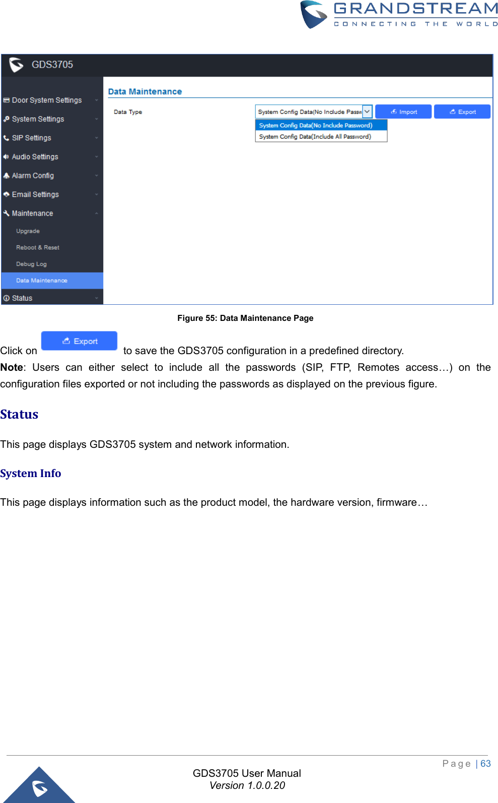
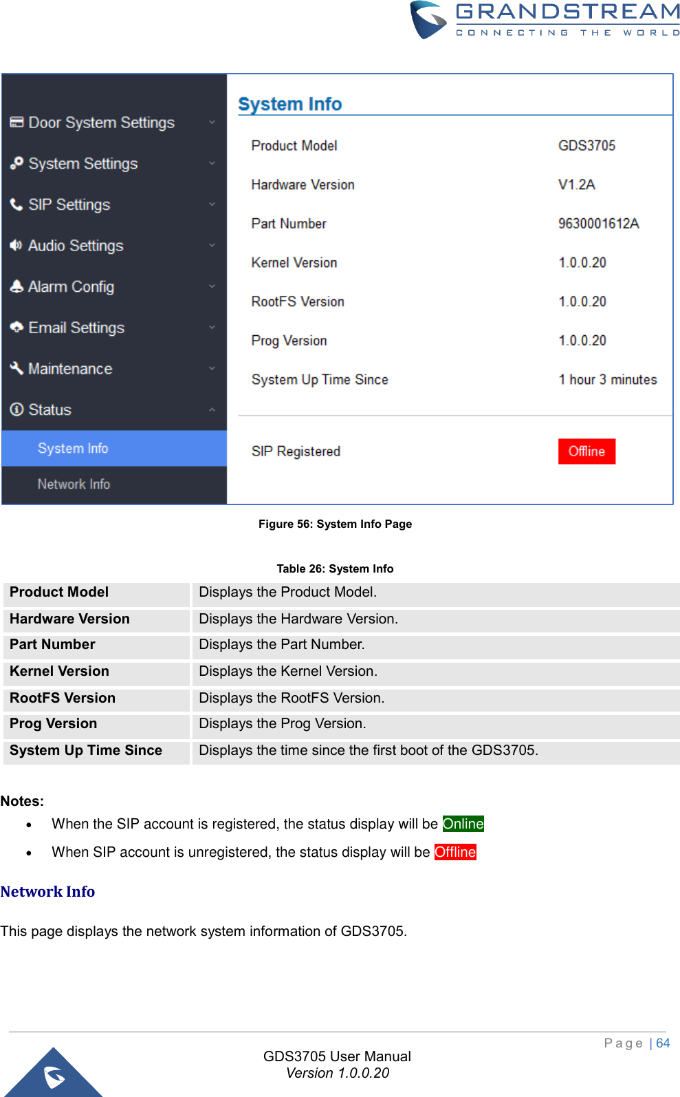
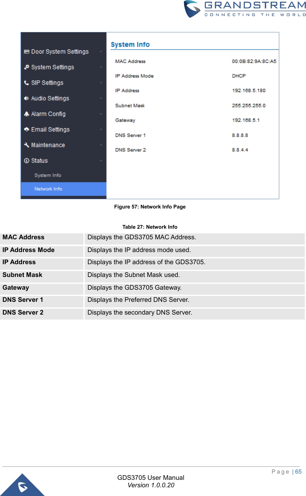
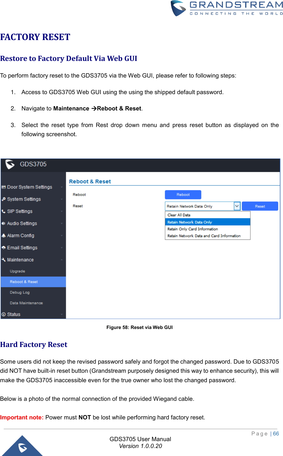
GDS3705 User Manual
User Manual
Navigation menu
Upload a User Manual
Namespaces
Wiki Guide
HTML
PDF
Info
Views
User Manual
Discussion / Help
Navigation

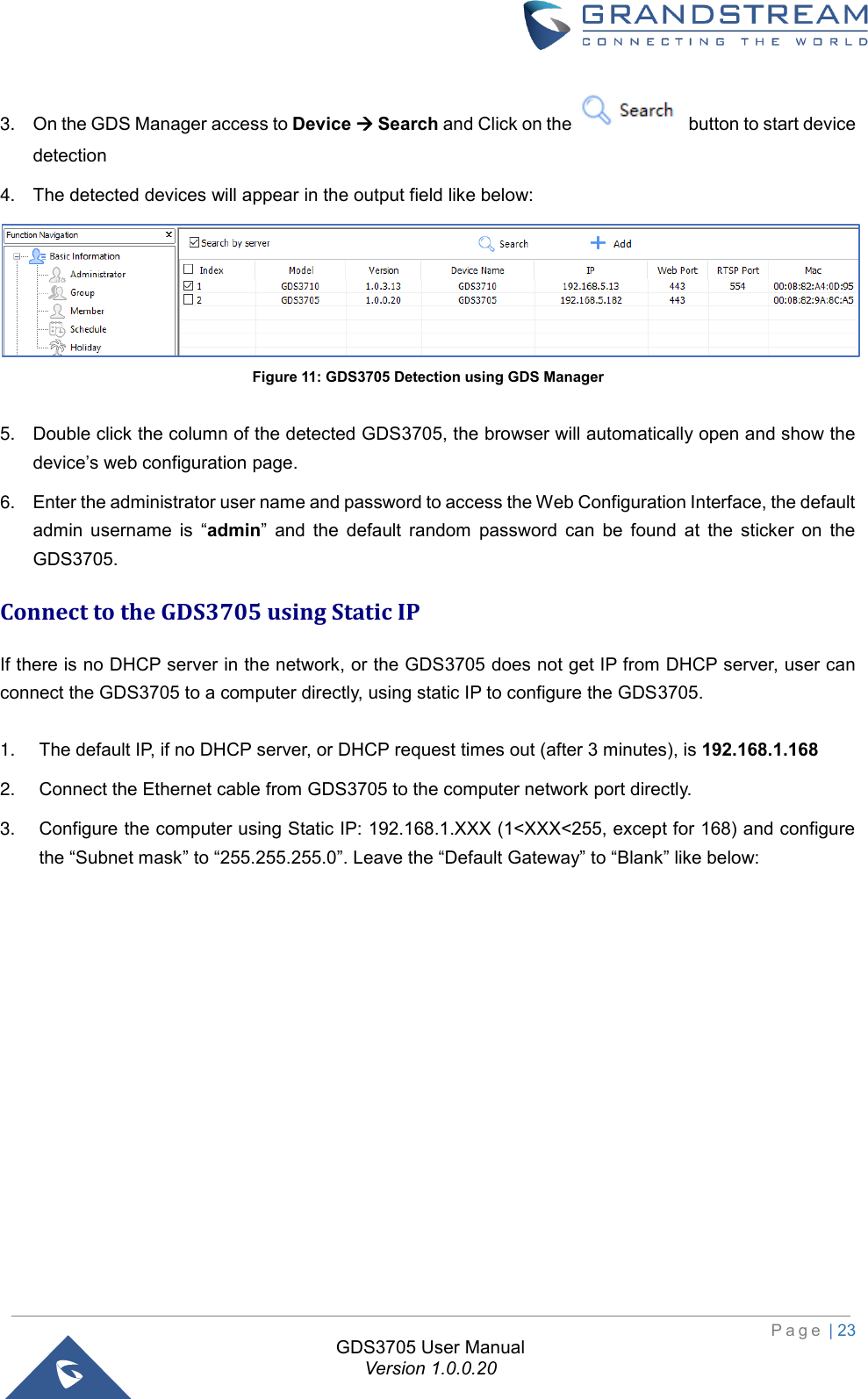
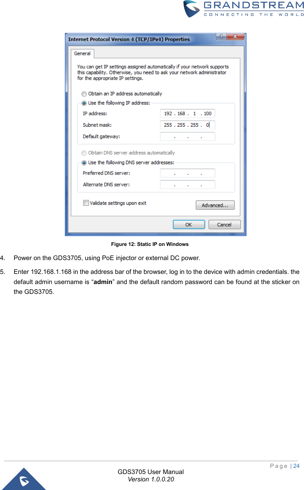
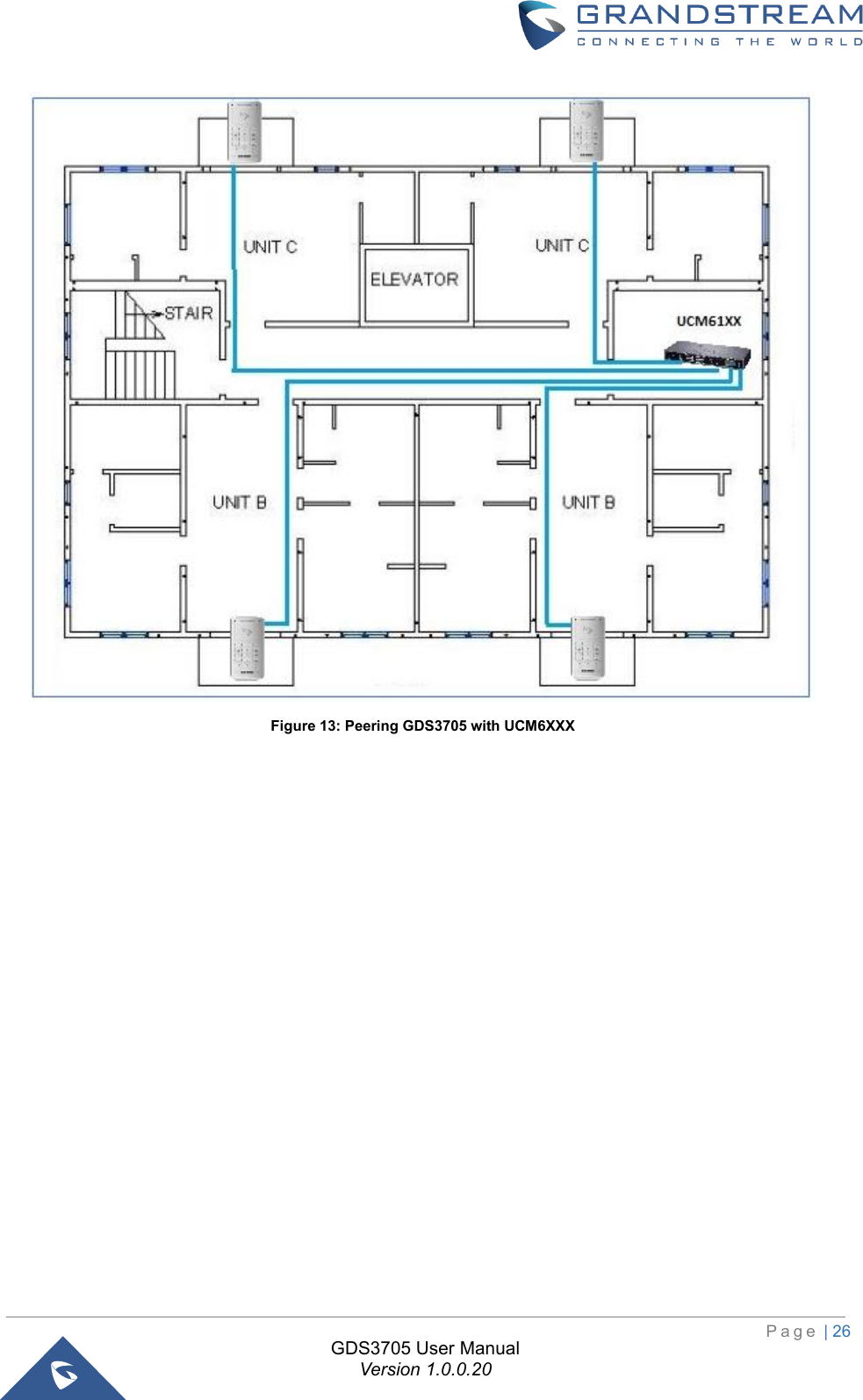
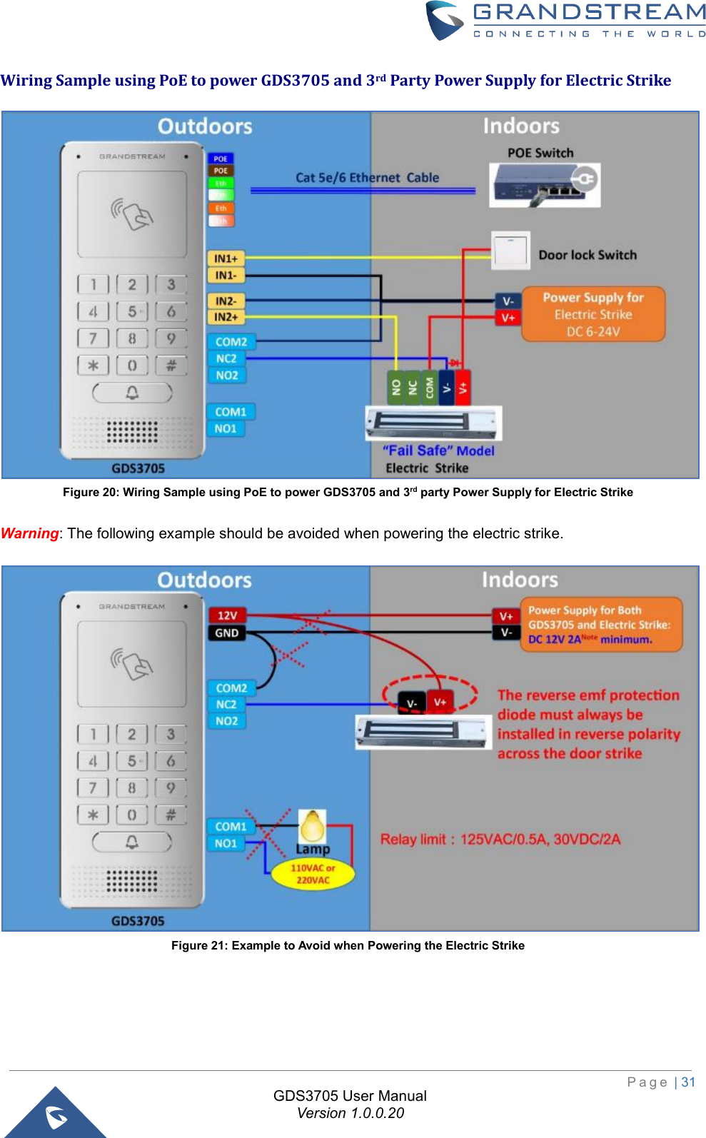
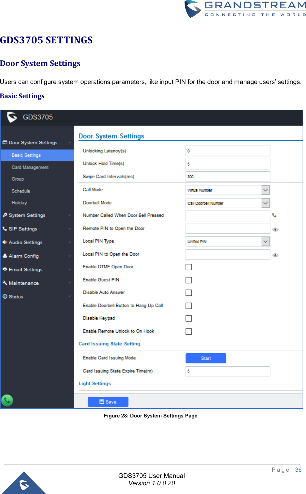
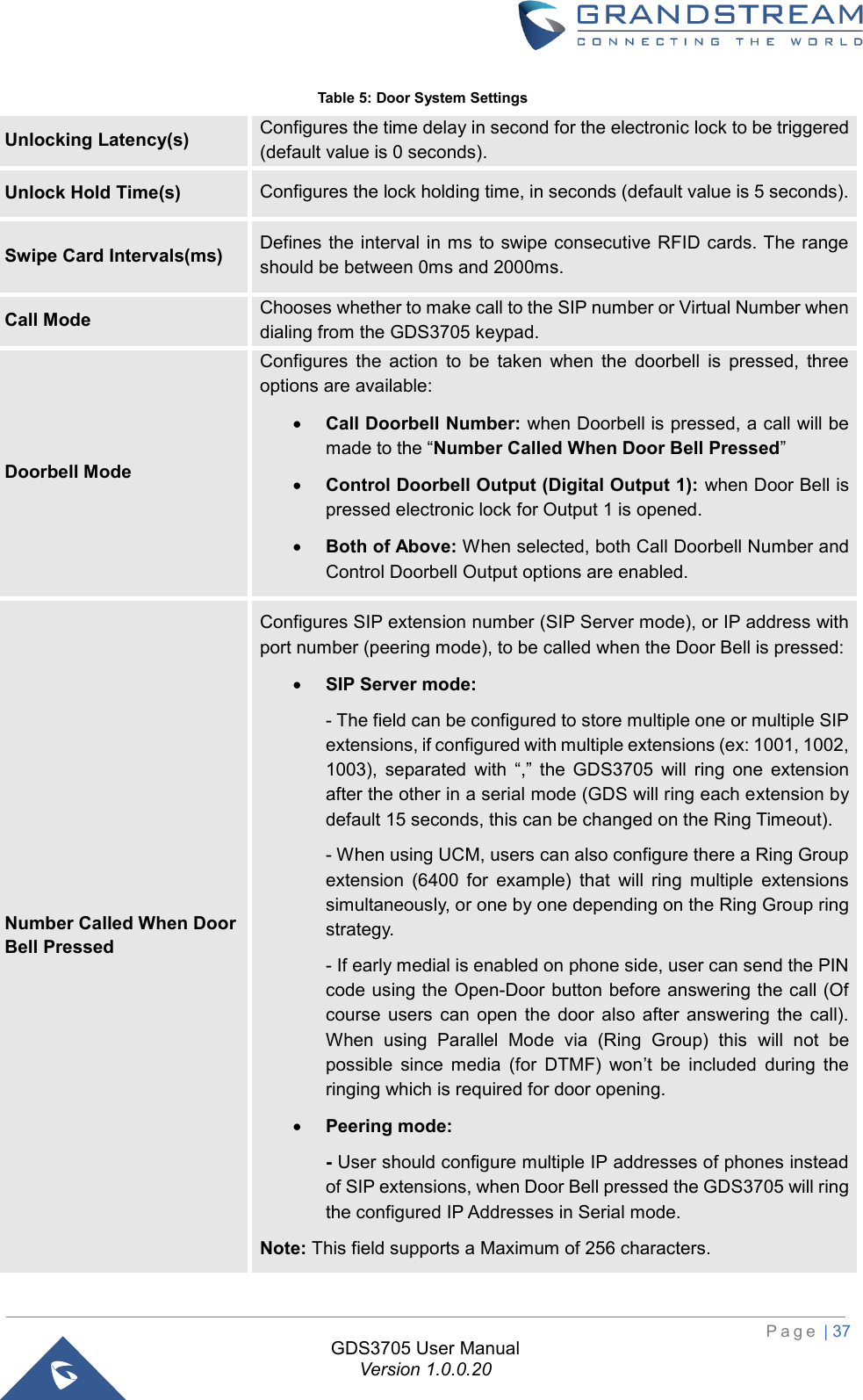
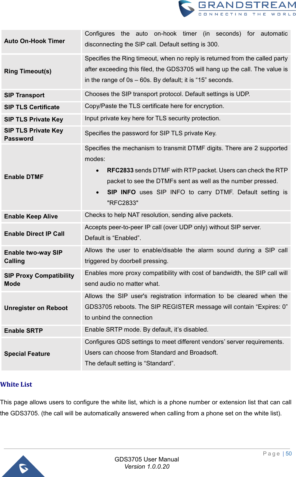
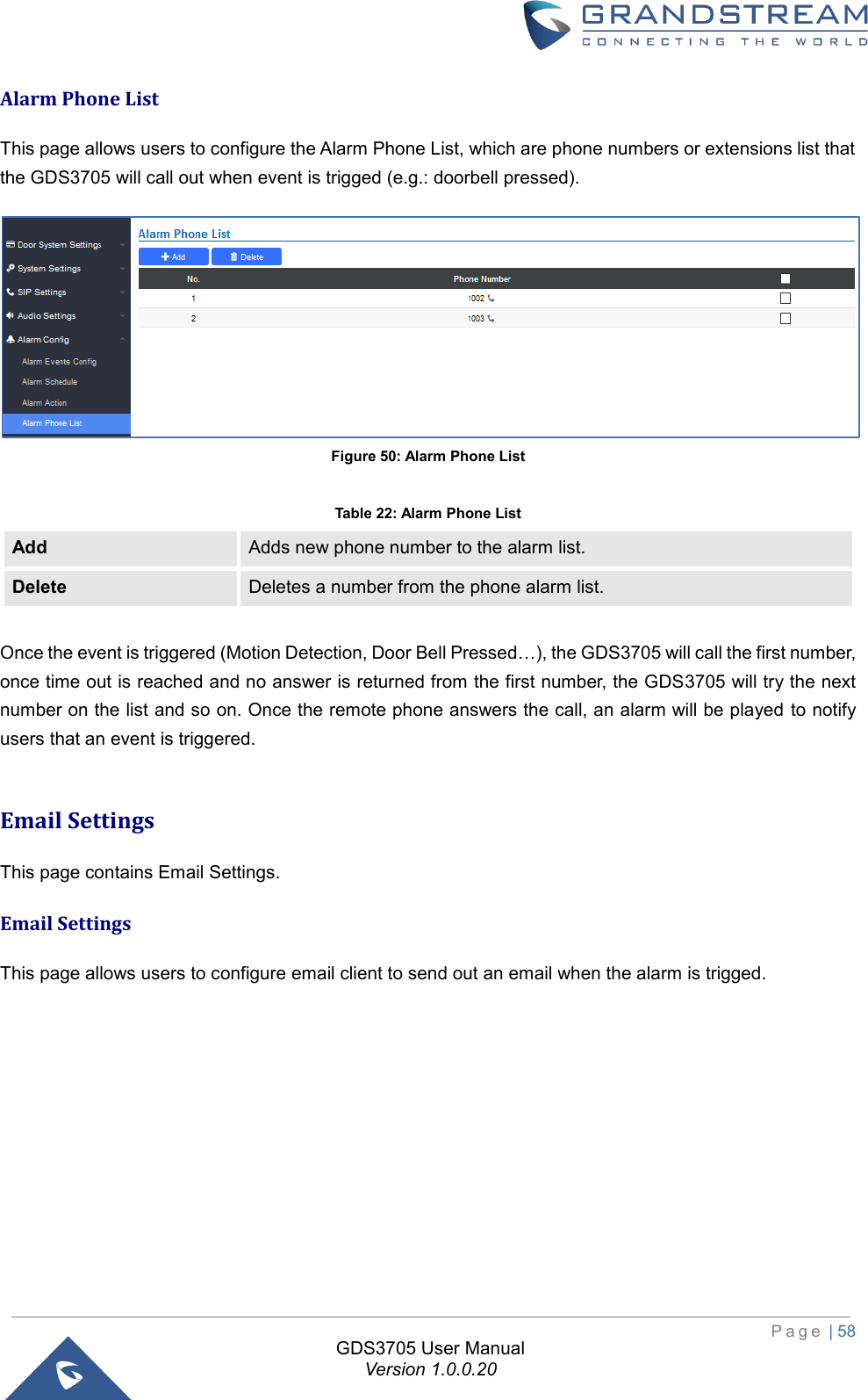
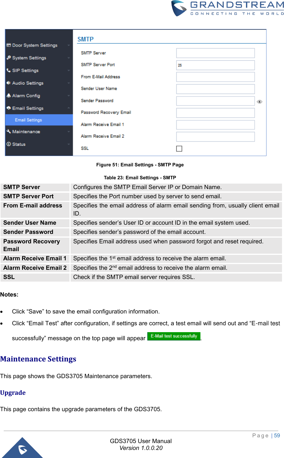
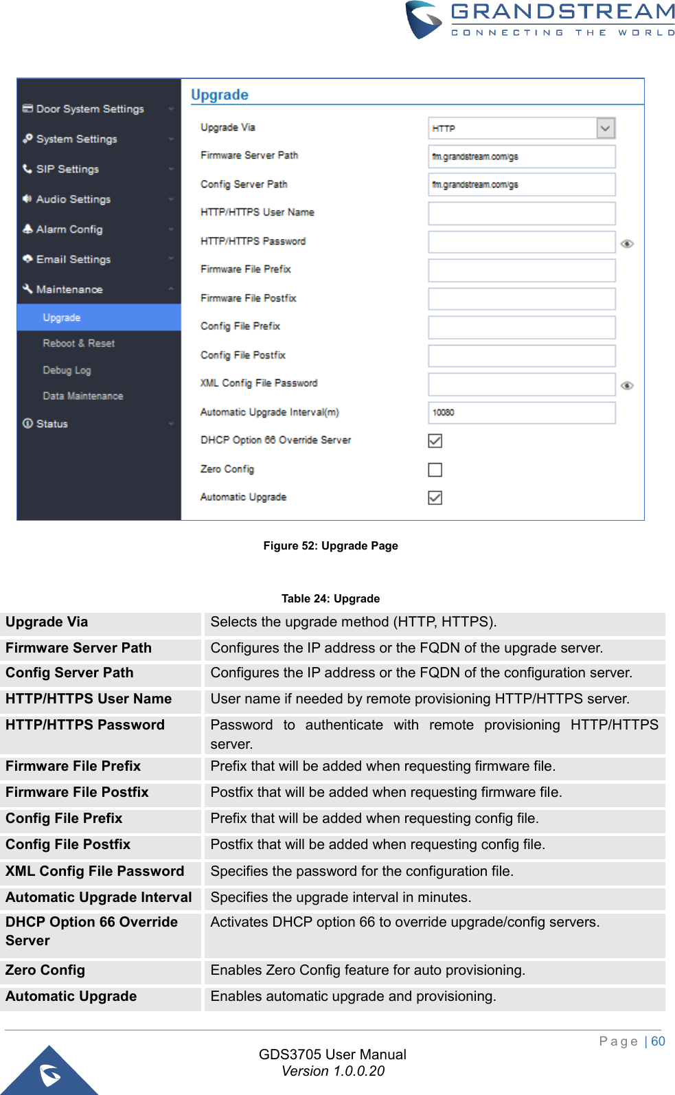
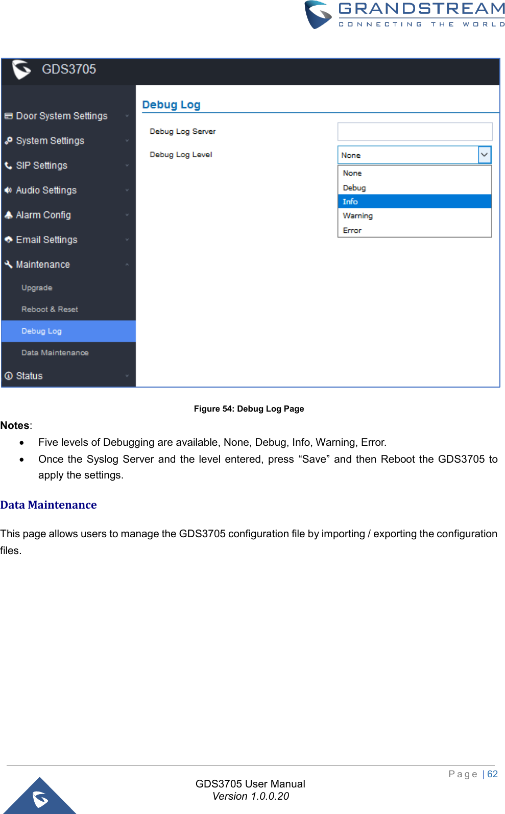
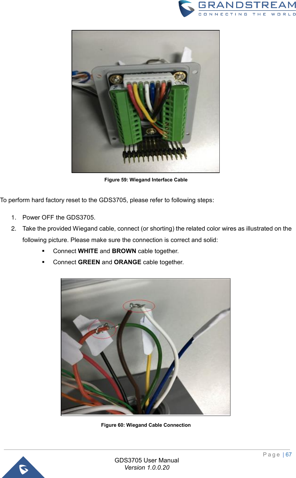
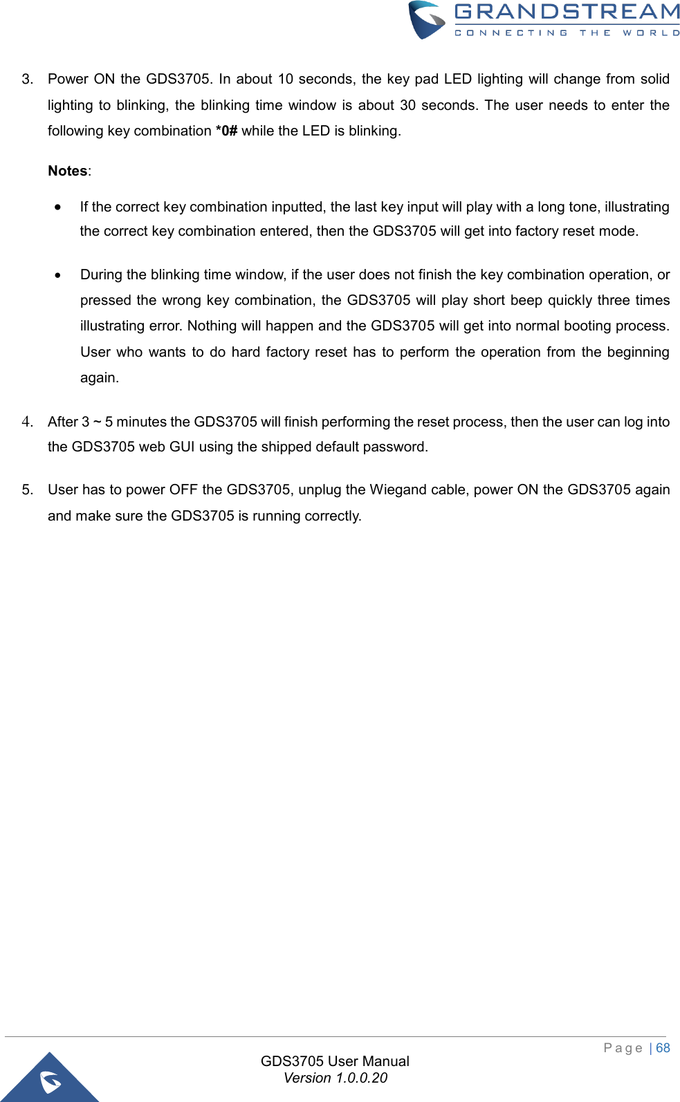
![P a g e | 38 GDS3705 User Manual Version 1.0.0.20 Remote PIN to Open the Door Configures PIN code stored in the GDS3705, remote SIP phone needs to input and match this PIN (the PIN is sent via DTMF while in call) so that the GDS3705 can open the door. Local PIN Type Three Options are available: Private Card PIN, Unified PIN or Card and Private PIN. • Private Card PIN: Means every member has a private PIN, the GDS will record who unlocked the door every time. Users need to enter the following sequence from the GDS3705 to open the door [*Virtual Number*Private Door Password#]. Note: When Local PIN type is set to private card PIN, users can also open the door by swiping their cards. • Unified PIN: Means all members share a same PIN to unlock the door. Users need to enter the following sequence from the GDS3705 keypad to open the door [*Local PIN to Open the Door#]. • Card and Private PIN: Means every member needs to swipe his card and enter his private PIN to open the door using the following sequence [Swipe the card + *Local PIN to Open the Door#] Local PIN to Open the Door Configures PIN stored in GDS3705, input locally this PIN on the GDS3705 keypad will unlock the door. This feature needs Private Card PIN, means every member has a private PIN, the GDS will record who unlocked the door every time. Users need to enter the following sequence from the GDS3705 to open the door [*Virtual Number*Private Door Password#]. Note: When local PIN type is set to private card PIN, users can also open the door by swiping their cards. Enable DTMF Open Door When enabled, remote SIP phones can open the door while in call by entering the remote PIN code configured (the PIN code is sent via DTMF). Default settings is disabled. Enable Guest PIN Enables password entry for guests. Guest PIN Configures the password that will be used by guests. Guest PIN Duration Start Time Selects the start time when the Guest PIN start to take effect. Guest PIN Duration End Time Selects the end time when the Guest PIN will stop working. Disable Auto Answer If checked, GDS3705 will not answer incoming calls automatically, users can press any key to answer the call. Default setting in unchecked. Disable Keypad When checked the Keypad will be disabled, only Door Bell button can be pressed. Enable Remote Unlock to On Hook When checked calls will be disconnected automatically 5 seconds after the remote open door event. Enable Doorbell Button to Hang UP Call When checked the door bell will allow users to hang up the ongoing call.](https://usermanual.wiki/Grandstream-Networks/GDS3705/User-Guide-3870626-Page-38.png)
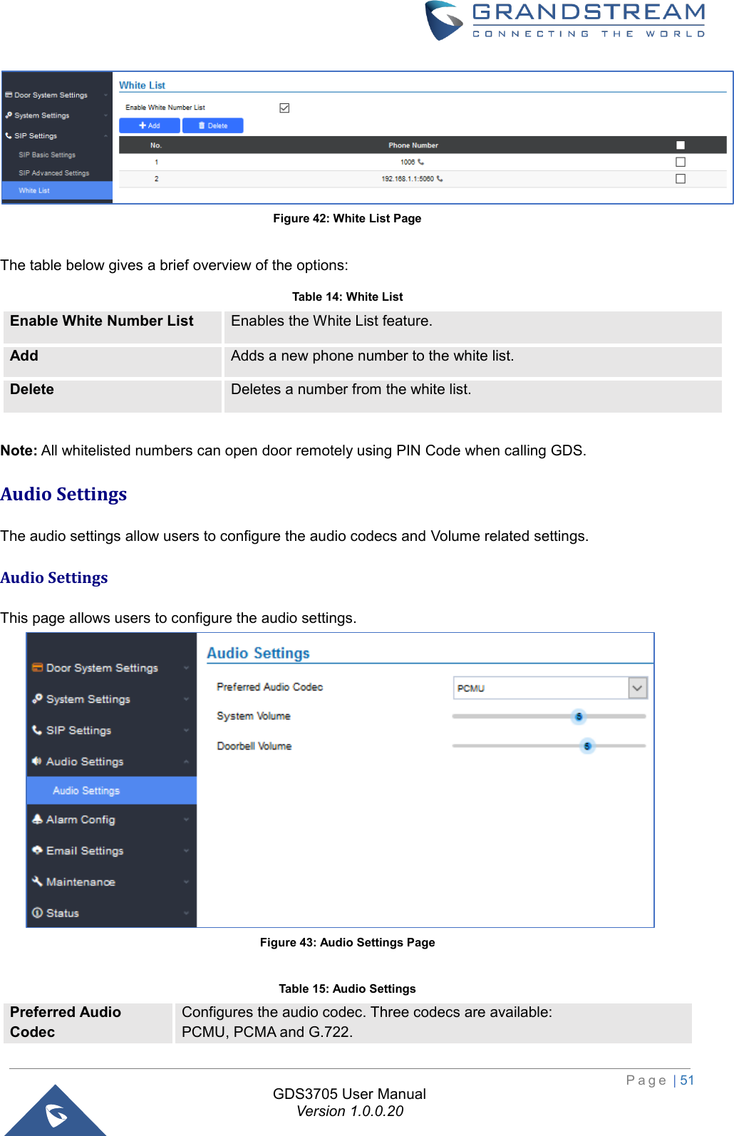
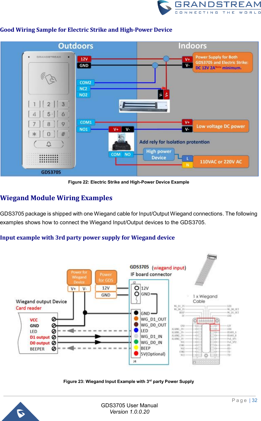
![P a g e | 39 GDS3705 User Manual Version 1.0.0.20 Enable Card Issuing Mode Enables RFID card issuing/program into the GDS3705. When selected sweeping an RFID card into the GDS3705 will add card information into. [Card Management] Card issuing State Expire Time(m) Card issuing mode will be automatically disabled when timer reached (The range of value is 1 – 1440, in minutes). Enable Key Blue Light When checked, the blue light will be activated when pressing the GDS3705 Keys. Enable Blue Light When enabled, Keypad LED will light based on the configured Start/End Time. For instance, this option can be used when GDS is deployed on dark environment, the GDS will be located easily using Keypad LED. Central Mode If enabled, Group/Schedule/Holiday can only be synchronized from the Central (GDS Manager), local configuration will not be allowed. If disabled, only local configuration from GDS3705 is allowed. Default setting is “Disabled”. Key Tone Type Configures the key tones for the GDS3705. • Default: Beeps will be played when pressing the GDS3705 keys. • DTMF: Tones will be played when pressing the GDS3705 keys. • Mute: No sound will be played when pressing keys. Wiegand Input Enable Enable Wiegand Input. Wiegand Output Enable Enable Wiegand Output. Notes: Remote SIP phone needs password (digits 0-9 only, ended with # key) matching the configuration on the web page to open the door (via DTMF). GDS3705 support RFID for multiple users to open door, therefore every user has its own PIN. For environment with 100 users and more, it’s difficult for the GDS3705 to manage all these users and a separate PC or Server should be involved for such kind of management and monitoring. In environments with more than 100 users the GDS3705, another possibility would be to set one unified Local PIN for opening the door for all the users. Card Management This page allows users to add information about RFID cards, two options are possible either add RFID cards manually or automatically. Figure 29: Card Management](https://usermanual.wiki/Grandstream-Networks/GDS3705/User-Guide-3870626-Page-39.png)
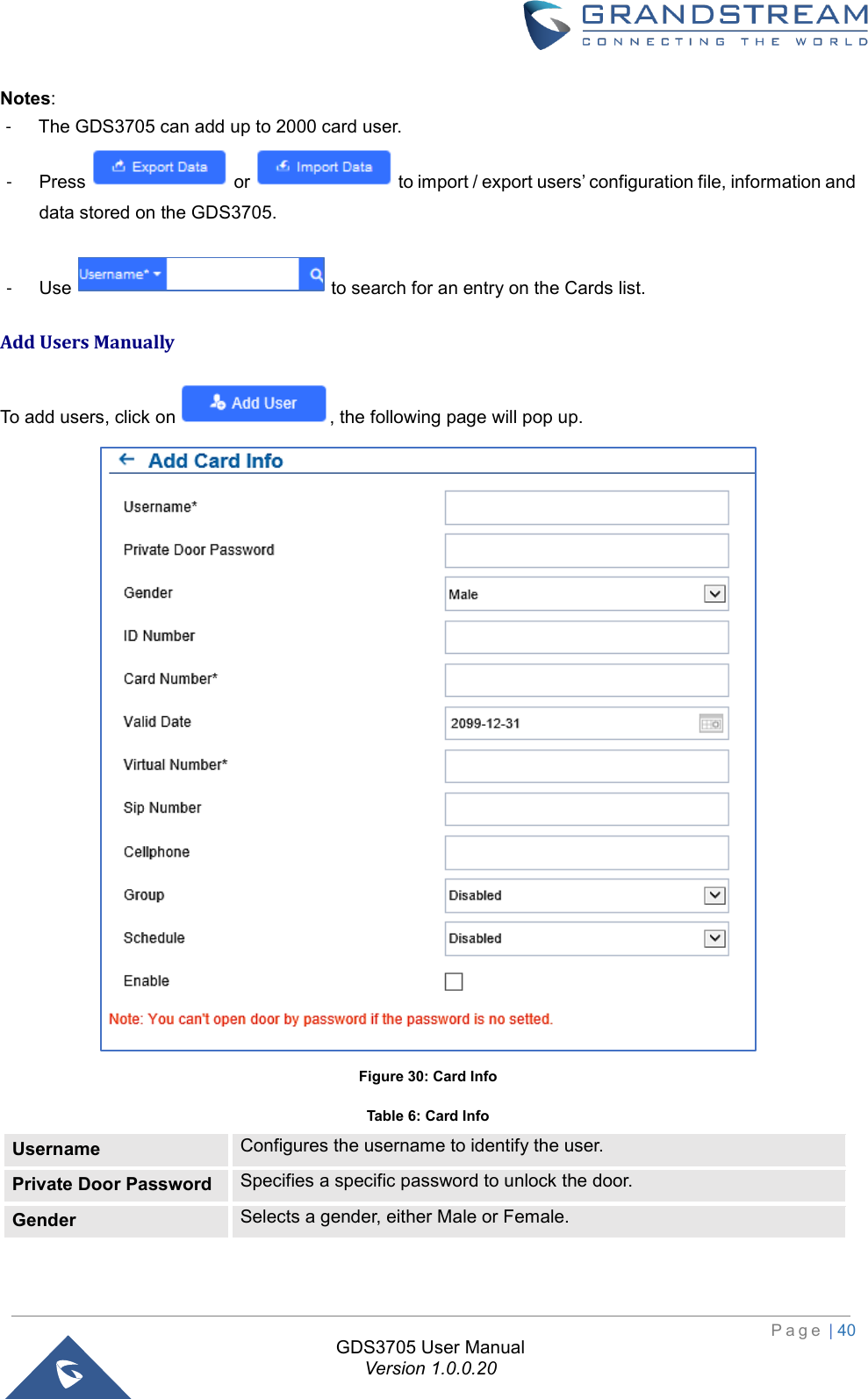
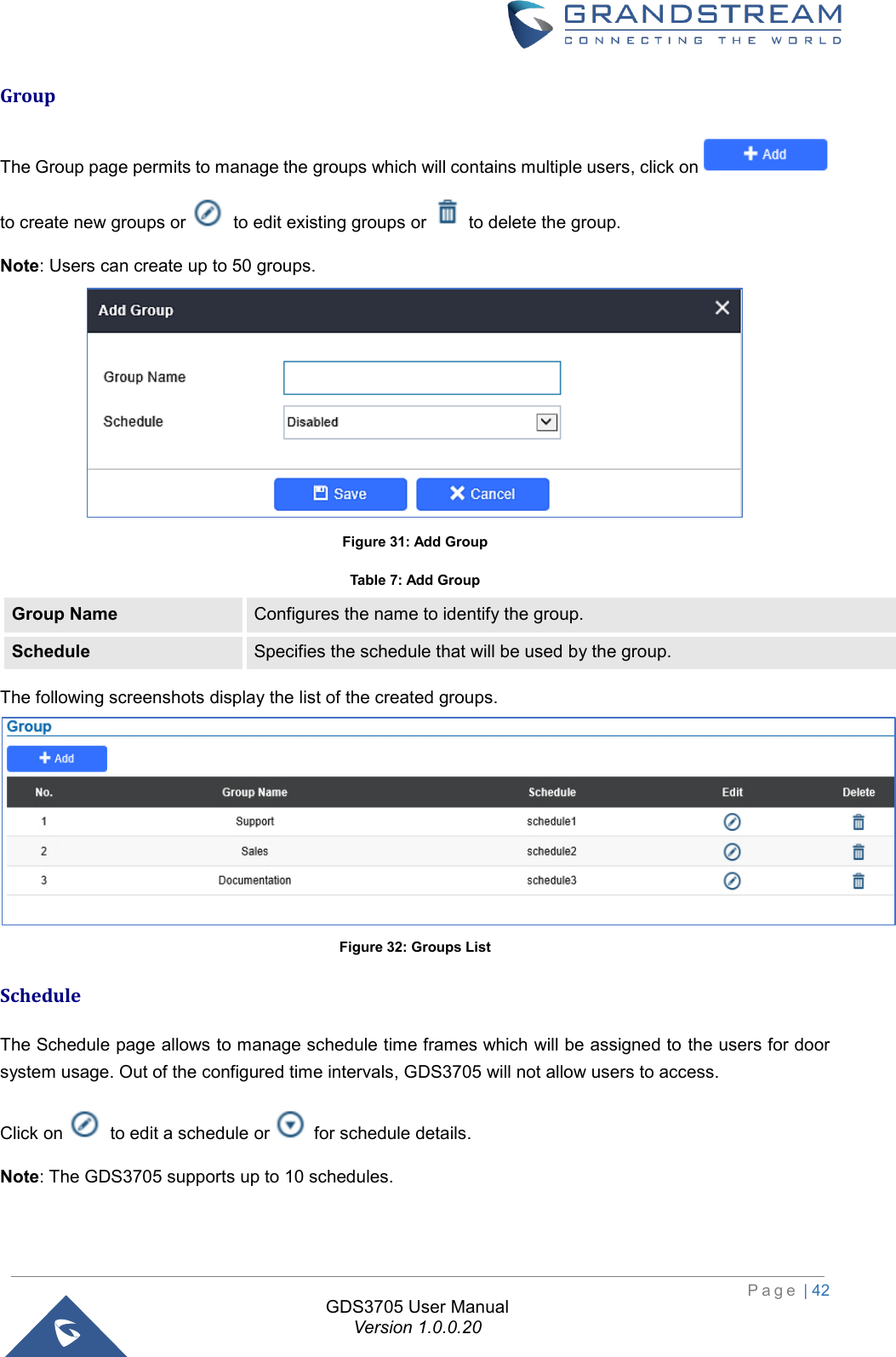
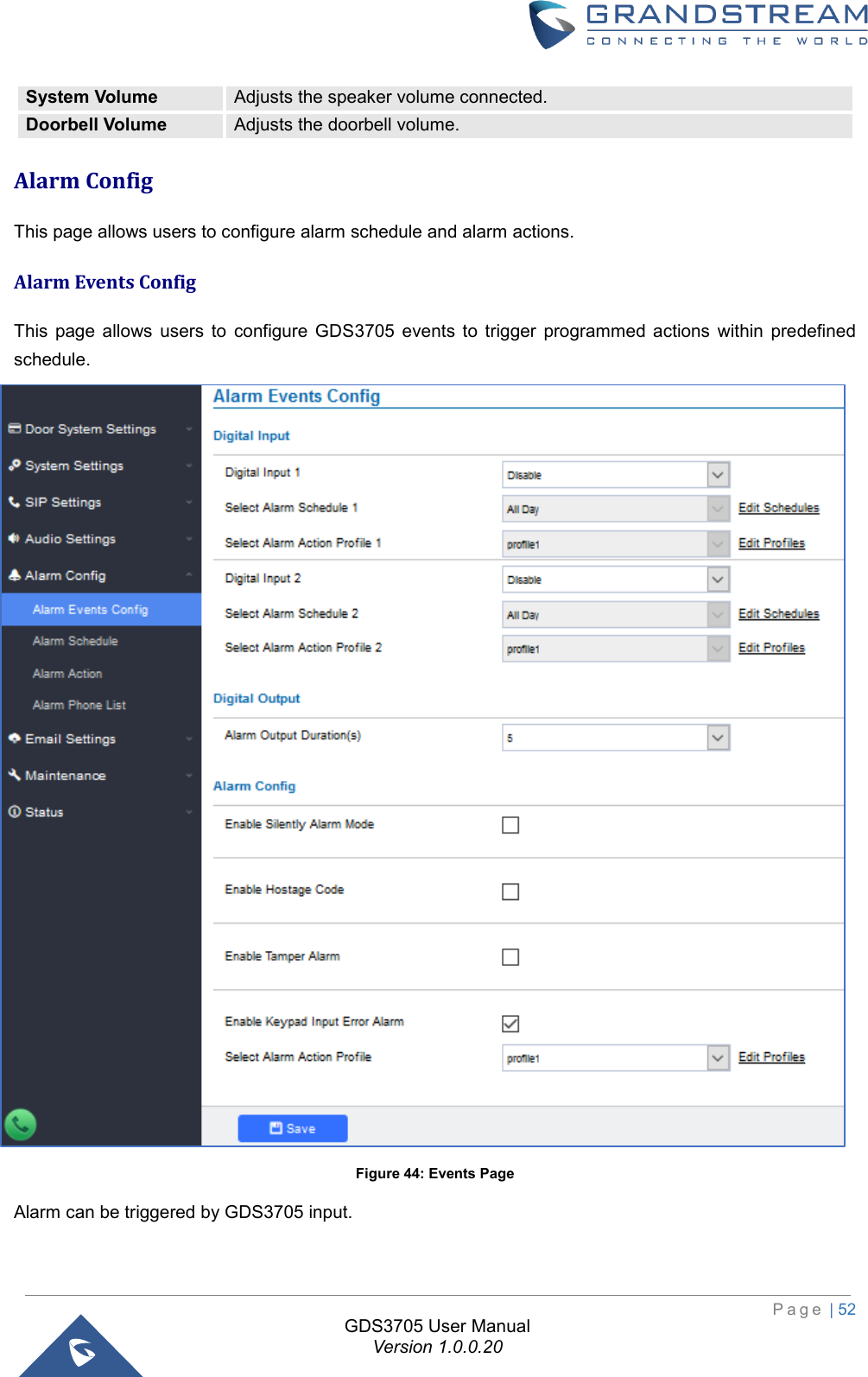
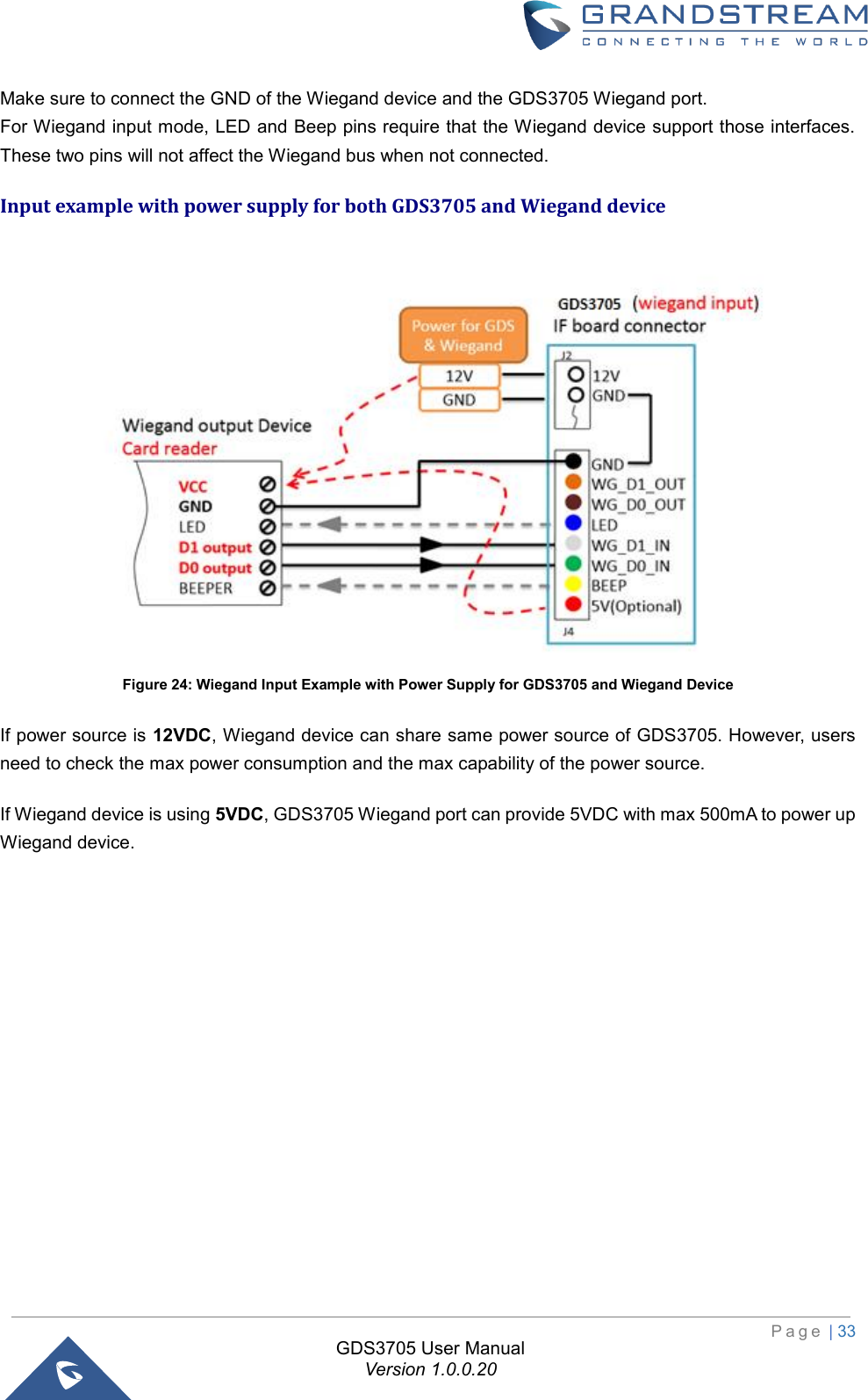
![P a g e | 41 GDS3705 User Manual Version 1.0.0.20 ID Number Enters an ID number (This number is set by the admin to identify each user uniquely). Card Number Enters the RFID Card number (this is the number written on the RFID card. When “card issuing mode” is enabled, this filed will be added automatically. Valid Date Configures the date of validity of the RFID card. Virtual Number When dialing directly from the keypad, the GDS accept only Virtual number to identify a user, once the Virtual number is typed followed by # key, the SIP Number will be dialed. SIP Number Configures the SIP Number which is mapped with virtual number. Once the virtual number is dialed the GDS3705 will send an INVITE to the SIP Number. Note: The SIP Number can be configured with an extension/phone number or IP address. Example: 192.168.5.124 Cellphone Configures cellphone of the user. Group Specifies to which group the user will be added. Schedule Specifies the schedule that will be assigned to the user. Enable Enable/Disable the RFID card. Notes: - Group overrides Schedule. - If Schedule is set as “Disabled” the RFID Card will be accepted when swiped. Add Users Automatically If [Enable Card Issuing Mode] is checked, the GDS3705 keypad will start blinking and once an RFID card is swiped, data stored on the card will be added into the GDS3705 card management page, user can still edit the entry added automatically by modifying some fields. Users Operation - Click on to edit the entry or show details of the entry. - Select the entries and click on to delete the selected users. - Click to refresh the data entered to the GDS3705. - Users can use to navigate through User Management pages.](https://usermanual.wiki/Grandstream-Networks/GDS3705/User-Guide-3870626-Page-41.png)