Grandstream Networks GDS3705 IP Audio Door System User Manual
Grandstream Networks, Inc. IP Audio Door System
User Manual
Grandstream Networks, Inc.
GDS3705
Audio Door Access System
User Manual

P a g e | 2
GDS3705 User Manual
Version 1.0.0.20
COPYRIGHT
©2018 Grandstream Networks, Inc. http://www.grandstream.com
All rights reserved. Information in this document is subject to change without notice. Reproduction or
transmittal of the entire or any part, in any form or by any means, electronic or print, for any purpose without
the express written permission of Grandstream Networks, Inc. is not permitted.
The latest electronic version of this user manual is available for download here:
http://www.grandstream.com/support
Grandstream is a registered trademark and Grandstream logo is trademark of Grandstream Networks, Inc.
in the United States, Europe and other countries.
CAUTION
Changes or modifications to this product not expressly approved by Grandstream, or operation of this
product in any way other than as detailed by this User Manual, could void your manufacturer warranty.
WARNING
Please do not use a different power adaptor with your devices as it may cause damage to the products and
void the manufacturer warranty.

P a g e | 3
GDS3705 User Manual
Version 1.0.0.20
GNU GPL INFORMATION
GDS3705 firmware contains third-party software licensed under the GNU General Public License (GPL).
Grandstream uses software under the specific terms of the GPL. Please see the GNU General Public
License (GPL) for the exact terms and conditions of the license.
Grandstream GNU GPL related source code can be downloaded from Grandstream web site from:
http://www.grandstream.com/support/faq/gnu-general-public-license/gnu-gpl-information-download

P a g e | 4
GDS3705 User Manual
Version 1.0.0.20
Table of Contents
CHANGE LOG .............................................................................................................. 10
Firmware Version 1.0.0.20 ................................................................................................................... 10
DOCUMENT PURPOSE ............................................................................................... 11
WELCOME ................................................................................................................... 12
PRODUCT OVERVIEW ................................................................................................ 13
Feature Highlights ................................................................................................................................ 13
Technical Specifications ....................................................................................................................... 13
GETTING STARTED ..................................................................................................... 15
Equipment Packaging .......................................................................................................................... 15
Description of the GDS3705 ................................................................................................................ 16
Connecting and Setting up the GDS3705............................................................................................ 16
GDS3705 Wiring Connection ............................................................................................................... 17
GDS3705 Back Cover Connections .................................................................................................... 18
Connection Example ............................................................................................................................ 18
Power GDS3705 using PoE ......................................................................................................... 19
Power GDS3705 using PSU ......................................................................................................... 19
GETTING TO KNOW GDS3705 ................................................................................... 20
Connecting GDS3705 to Network with DHCP Server ......................................................................... 20
Windows Platform ......................................................................................................................... 20
UPnP ..................................................................................................................................................... 20
GS Search ............................................................................................................................................. 21
GDS Manager Utility Tool ...................................................................................................................... 22
Connect to the GDS3705 using Static IP............................................................................................. 23
GDS3705 APPLICATION SCENARIOS ....................................................................... 25
Peering Mode without SIP Server ........................................................................................................ 25

P a g e | 5
GDS3705 User Manual
Version 1.0.0.20
Peering using SIP Server (UCM6XXX) ................................................................................................ 25
GDS3705 PERIPHERAL CONNECTIONS ................................................................... 27
Alarm IN/OUT ...................................................................................................................................... 28
Protection Diode .................................................................................................................................. 29
Connection Examples .......................................................................................................................... 29
Wiring Sample using 3rd Party Power Supply ............................................................................... 30
Wiring Sample using Power Supply for both GDS3705 and Electric Strike ................................. 30
Wiring Sample using PoE to power GDS3705 and 3rd Party Power Supply for Electric Strike .... 31
Good Wiring Sample for Electric Strike and High-Power Device ................................................. 32
Wiegand Module Wiring Examples ...................................................................................................... 32
Input example with 3rd party power supply for Wiegand device .................................................. 32
Input example with power supply for both GDS3705 and Wiegand device ................................. 33
Output example with 3rd party power supply for Wiegand device ................................................ 34
Wiegand RFID Card Reader Example ......................................................................................... 34
GDS3705 HOME WEB PAGE....................................................................................... 35
GDS3705 SETTINGS .................................................................................................... 36
Door System Settings .......................................................................................................................... 36
Basic Settings ............................................................................................................................... 36
Card Management ........................................................................................................................ 39
Add Users Manually .............................................................................................................................. 40
Add Users Automatically ....................................................................................................................... 41
Users Operation .................................................................................................................................... 41
Group ............................................................................................................................................ 42
Schedule ....................................................................................................................................... 42
Holiday .......................................................................................................................................... 43
System Settings ................................................................................................................................... 44
Date & Time Settings .................................................................................................................... 44
Network Settings ........................................................................................................................... 44
Access Settings ............................................................................................................................ 46
User Management ........................................................................................................................ 47

P a g e | 6
GDS3705 User Manual
Version 1.0.0.20
SIP Settings ......................................................................................................................................... 47
SIP Basic Settings ........................................................................................................................ 47
SIP Advanced Settings ................................................................................................................. 49
White List ...................................................................................................................................... 50
Audio Settings ...................................................................................................................................... 51
Audio Settings ............................................................................................................................... 51
Alarm Config ........................................................................................................................................ 52
Alarm Events Config ..................................................................................................................... 52
Digital Input ........................................................................................................................................... 53
Alarm Output ......................................................................................................................................... 53
Silently Alarm Mode .............................................................................................................................. 53
Hostage Code ....................................................................................................................................... 54
Tamper Alarm ....................................................................................................................................... 54
Keypad Input Error Alarm ...................................................................................................................... 54
Alarm Schedule ............................................................................................................................ 55
Alarm Action .................................................................................................................................. 56
Alarm Phone List .......................................................................................................................... 58
Email Settings ...................................................................................................................................... 58
Email Settings ............................................................................................................................... 58
Maintenance Settings .......................................................................................................................... 59
Upgrade ........................................................................................................................................ 59
Reboot & Reset ............................................................................................................................ 61
Debug Log .................................................................................................................................... 61
Data Maintenance ......................................................................................................................... 62
Status ................................................................................................................................................... 63
System Info ................................................................................................................................... 63
Network Info .................................................................................................................................. 64
FACTORY RESET ........................................................................................................ 66
Restore to Factory Default Via Web GUI ............................................................................................. 66
Hard Factory Reset .............................................................................................................................. 66
EXPERIENCING THE GDS3705 .................................................................................. 69

P a g e | 7
GDS3705 User Manual
Version 1.0.0.20
Table of Tables
Table 1: GDS3705 Features in a Glance .................................................................................................... 13
Table 2: GDS3705 Technical Specifications ............................................................................................... 13
Table 3: Equipment Packaging ................................................................................................................... 15
Table 4: GDS3705 Wiring Connection ........................................................................................................ 17
Table 5: Door System Settings .................................................................................................................... 37
Table 6: Card Info ........................................................................................................................................ 40
Table 7: Add Group ..................................................................................................................................... 42
Table 8: Date & Time ................................................................................................................................... 44
Table 9: Basic Settings ................................................................................................................................ 45
Table 10: Access Settings ........................................................................................................................... 46
Table 11: User Management ....................................................................................................................... 47
Table 12: SIP Basic Settings ....................................................................................................................... 48
Table 13: SIP Advanced Settings ................................................................................................................ 49
Table 14: White List ..................................................................................................................................... 51
Table 15: Audio Settings .............................................................................................................................. 51
Table 16: Digital Input .................................................................................................................................. 53
Table 17: Silently Alarm Mode ..................................................................................................................... 53
Table 18: Hostage Code Alarm ................................................................................................................... 54
Table 19: Tamper Alarm .............................................................................................................................. 54
Table 20: Keypad Input Error Alarm ............................................................................................................ 54
Table 21: Alarm Actions ............................................................................................................................... 57
Table 22: Alarm Phone List ......................................................................................................................... 58
Table 23: Email Settings - SMTP ................................................................................................................ 59
Table 24: Upgrade ....................................................................................................................................... 60
Table 25: Reset & Reboot ........................................................................................................................... 61
Table 26: System Info .................................................................................................................................. 64
Table 27: Network Info ................................................................................................................................ 65

P a g e | 8
GDS3705 User Manual
Version 1.0.0.20
Table of Figures
Figure 1: GDS3705 Package ...................................................................................................................... 15
Figure 2: GDS3705 Front View ................................................................................................................... 16
Figure 3: GDS3705 Back View ................................................................................................................... 16
Figure 4: GDS3705 Back Cover Connections ............................................................................................ 18
Figure 5: GDS3705 Back Cover ................................................................................................................. 18
Figure 6: Connection Example .................................................................................................................... 19
Figure 7: Powering the GDS3705 ............................................................................................................... 19
Figure 8: Detecting GDS3705 via UPnP ..................................................................................................... 20
Figure 9: GDS3705 Login Page .................................................................................................................. 21
Figure 10: GS Search Discovery ................................................................................................................ 22
Figure 11: GDS3705 Detection using GDS Manager ................................................................................. 23
Figure 12: Static IP on Windows ................................................................................................................. 24
Figure 13: Peering GDS3705 with UCM6XXX ............................................................................................ 26
Figure 14: Peripheral Connections for GDS3705 ....................................................................................... 27
Figure 15: Alarm_In/Out Circuit for GDS3705 ............................................................................................. 28
Figure 16: Protection Diode - Example 1 .................................................................................................... 29
Figure 17: Protection Diode - Example 2 .................................................................................................... 29
Figure 18: 3rd party Power Supply Wiring Sample ...................................................................................... 30
Figure 19: Power Supply used for both GDS3705 and Electric Strike ....................................................... 30
Figure 20: Wiring Sample using PoE to power GDS3705 and 3rd party Power Supply for Electric Strike . 31
Figure 21: Example to Avoid when Powering the Electric Strike ................................................................ 31
Figure 22: Electric Strike and High-Power Device Example ....................................................................... 32
Figure 23: Wiegand Input Example with 3rd party Power Supply ................................................................ 32
Figure 24: Wiegand Input Example with Power Supply for GDS3705 and Wiegand Device ..................... 33
Figure 25: Wiegand Output Wiring Example............................................................................................... 34
Figure 26: Wiegand RFID Card Reader Example ...................................................................................... 34
Figure 27: Change Language Page ............................................................................................................ 35
Figure 28: Door System Settings Page ....................................................................................................... 36
Figure 29: Card Management ..................................................................................................................... 39
Figure 30: Card Info .................................................................................................................................... 40
Figure 31: Add Group .................................................................................................................................. 42
Figure 32: Groups List ................................................................................................................................. 42
Figure 33: Edit Schedule Time .................................................................................................................... 43
Figure 34: Edit Holiday Time ....................................................................................................................... 43
Figure 35: Date & Time Page ...................................................................................................................... 44
Figure 36: Basic Settings Page ................................................................................................................... 45
Figure 37: Access Settings Page ................................................................................................................ 46
Figure 38: User Management Page ............................................................................................................ 47
Figure 39: Password Recovery Email ......................................................................................................... 47

P a g e | 9
GDS3705 User Manual
Version 1.0.0.20
Figure 40: SIP Basic Settings Page ............................................................................................................ 48
Figure 41: SIP Advanced Settings Page ..................................................................................................... 49
Figure 42: White List Page .......................................................................................................................... 51
Figure 43: Audio Settings Page .................................................................................................................. 51
Figure 44: Events Page ............................................................................................................................... 52
Figure 45: Digital Input ................................................................................................................................ 53
Figure 46: Alarm Schedule .......................................................................................................................... 55
Figure 47: Edit Schedule ............................................................................................................................. 56
Figure 48: Alarm Action ............................................................................................................................... 57
Figure 49: Edit Alarm Action ........................................................................................................................ 57
Figure 50: Alarm Phone List ........................................................................................................................ 58
Figure 51: Email Settings - SMTP Page ..................................................................................................... 59
Figure 52: Upgrade Page ............................................................................................................................ 60
Figure 53: Reset & Reboot Page ................................................................................................................ 61
Figure 54: Debug Log Page ........................................................................................................................ 62
Figure 55: Data Maintenance Page ............................................................................................................ 63
Figure 56: System Info Page....................................................................................................................... 64
Figure 57: Network Info Page ..................................................................................................................... 65
Figure 58: Reset via Web GUI .................................................................................................................... 66
Figure 59: Wiegand Interface Cable ........................................................................................................... 67
Figure 60: Wiegand Cable Connection ....................................................................................................... 67

P a g e | 10
GDS3705 User Manual
Version 1.0.0.20
CHANGE LOG
This section documents significant changes from previous versions of user manual for GDS3705. Only
major new features or major document updates are listed here. Minor updates for corrections or editing are
not documented here.
Firmware Version 1.0.0.20
• This is the initial version for GDS3705.

P a g e | 11
GDS3705 User Manual
Version 1.0.0.20
DOCUMENT PURPOSE
This document describes the basic concept and tasks necessary to use and configure your GDS3705. And
it covers the topic of connecting and configuring the GDS3705, making basic operations and the call
features. Please visit http://www.grandstream.com/support to download the latest “GDS3705 User Manual”.
This guide covers following topics:
• Product Overview
• Getting Started
• Getting to Know GDS3705
• GDS3705 Application Scenarios
• GDS3705 Peripheral Connections
• GDS3705 Home Web Page
• GDS3705 Settings
• Factory Reset
• Experiencing the GDS3705

P a g e | 12
GDS3705 User Manual
Version 1.0.0.20
WELCOME
Thank you for purchasing Grandstream GDS3705 Audio Door Access System, an innovative IP based
powerful door system. The GDS3705 Audio Door Access system features industry-leading SIP/VoIP for 2-
way audio to SIP phones. It contains integrated PoE, HD loudspeaker, RFID card reader, and more.
GDS3705 IP Audio Door Access System can be managed by Grandstream’s free windows-based
management software: GDS Manager is a client/server based software which provided RFID card
management and basic reports for the door entrance. GDS3705 is ideal for entry places such as banks,
hotels, schools, office buildings, retail stores and small warehouses.
P a g e | 13
GDS3705 User Manual
Version 1.0.0.20
PRODUCT OVERVIEW
Feature Highlights
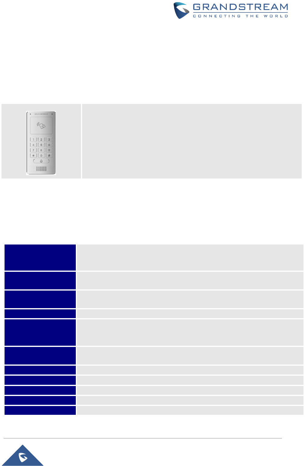
The following table contains the major features of the GDS3705.
Table 1: GDS3705 Features in a Glance
• Broad interoperability with most 3rd party SIP/VoIP devices and leading
SIP/NGN/IMS platforms.
• 2 Channels Input/Output alarm.
• RS485, Wiegand (26 bits) Input and Output.
• RFID card reader.
• Weather proof, vandal resistant.
Technical Specifications
The following table resumes all the technical specifications including the protocols / standards supported,
voice codecs, telephony features and upgrade/provisioning settings for GDS3705.
Table 2: GDS3705 Technical Specifications
Network Protocols
TCP/IP/UDP, RTP/RTCP, HTTP/HTTPS local upload and mass provisioning using
TR-069 (pending), ARP/RARP, ICMP, DNS, DHCP, SSH, SMTP, NTP, STUN, TLS,
SRTP.
SIP/VoIP Support
Broad interoperability with most 3rd party SIP/VoIP devices and leading
SIP/NGN/IMS platforms.
Voice Codecs
G.711µ/a-law, G.722, G.723.1, G.726-32, G.729A/B, iLBC, in-band and out-of-band
DTMF (in audio, RFC2833, SIP INFO), AEC.
QoS
Layer 2 QoS (802.1Q, 802.1P).
Security
User and administrator level access control (pending), MD5 and MD5-sess based
authentication, 256-bit AES encrypted configuration file, TLS, SRTP, HTTPS,
802.1Q.
Upgrade /
Provisioning
Firmware upgrade via HTTP/HTTPS, mass provisioning using TR-069 (Pending) or
AES encrypted XML configuration file.
Audio Input
Integrated dual microphones.
Audio Output
Built-in HD Loudspeaker (2 Watt), sound quality suitable for up to 3 m.
Keypad / Buttons
12-Metal Keys plus a Metal doorbell button.
RFID
125KHz: EM4100 (1 RFID card and 1 RFID key fob included).
Alarm Input
Yes, 2 channels, Vin < 15V, for door sensor or other devices.

P a g e | 14
GDS3705 User Manual
Version 1.0.0.20
Alarm Output
Yes, 2 channels, 125VAC/0.5A, 30VDC/2A, Normal Open or Normal Close, for
electric lock, light switch or other devices.
Network Interface
10M/100M auto-sensing.
Expansion Interface
RS485, Wiegand (26 bits) input and output.
Dimensions and
Weight
173mm(H) x 80mm(W) x 36mm(D).
0.6 Kg.
Power Supply
PoE (Power over Ethernet) IEEE 802.3af Class 3, or 12VDC/1A connection (AC
power adapter not included).
Ingress Protection
Weather proof, vandal resistant, with support for extra back reinforcing metal plate
Temperature and
Humidity
Operation: -30°C to 60°C (-22°F to 140°F)
Storage: -35°C to 60°C (-31°F to 140°F)
Humidity: 10% to 90% Non-condensing
Protection Class
IP66 (EN60529), IK09 (IEC62262).
Compliance
FCC: Part 15; Subpart B; Subpart C; MPE
CE: EN 55032; EN 50130; EN 61000-3-2; EN 61000-3-3; EN 60950-1; EN 300 330;
EN 301 489-1; EN 301 489-3; EN 62311
RCM: AS/NZS CISPR 22/24; AS/NZS 4268; AS/NZS 60950.1
IC: ICES-003; RSS310
P a g e | 15
GDS3705 User Manual
Version 1.0.0.20
GETTING STARTED
This chapter provides basic installation instructions including the list of the packaging contents and
information for obtaining the best performance using the GDS3705 Audio Access Door System.
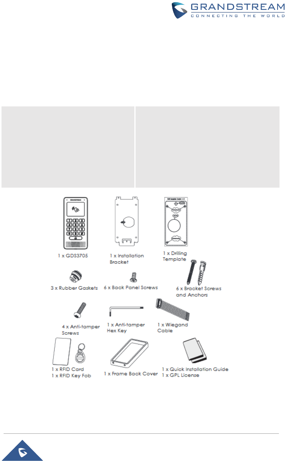
Equipment Packaging
Table 3: Equipment Packaging
• 1 x GDS3705
• 1 x Installation Bracket
• 1 x Drilling Template
• 3 x Rubber Gaskets (for sealing the
back cable)
• 6 x Back Panel Screws
• 6 x Bracket Screws and Anchors
• 4 x Anti-tamper screws
• 1 x Anti-Tamper Hex Key
• 1 x Wiegand Cable
• 1 x RFID Card (more can be purchased
from Partner/reseller)
• 1 x Key Fob (more can be purchased from
Partner/reseller)
• 1 x Frame Back Cover
• 1 x Quick Installation Guide
• 1 x GPL License
Figure 1: GDS3705 Package
Note: Check the package before installation. If you find anything missing, contact your system administrator
P a g e | 16
GDS3705 User Manual
Version 1.0.0.20
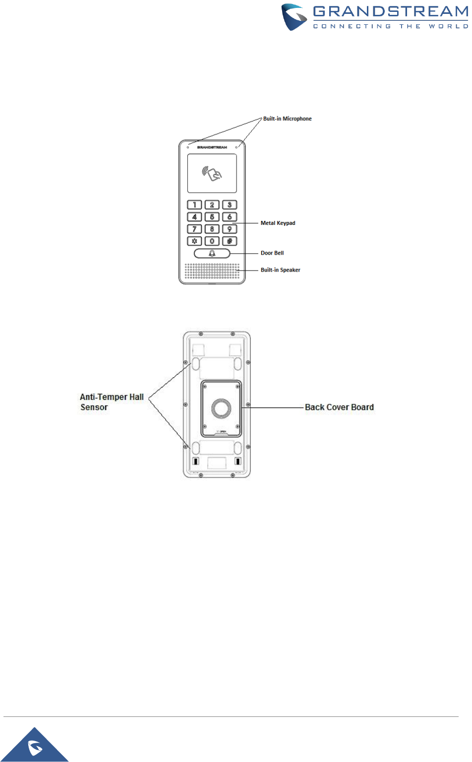
Description of the GDS3705
Below figures show the component of the back and front view of GDS3705 IP Audio Access Door System:
Figure 2: GDS3705 Front View
Figure 3: GDS3705 Back View
Connecting and Setting up the GDS3705
The GDS3705 can be powered using PoE or PSU:
Using PoE as power supply (Suggested)
• Connect the other end of the RJ45 cable to the PoE switch.
• PoE injector can be used if PoE switch is not available.
Using the power adapter as power supply (PSU not provided)
• Connect the other end of the RJ45 cable to network switch or router.
• Connect DC 12V power source via related cable to the corrected PIN of the GDS3705.
P a g e | 17
GDS3705 User Manual
Version 1.0.0.20
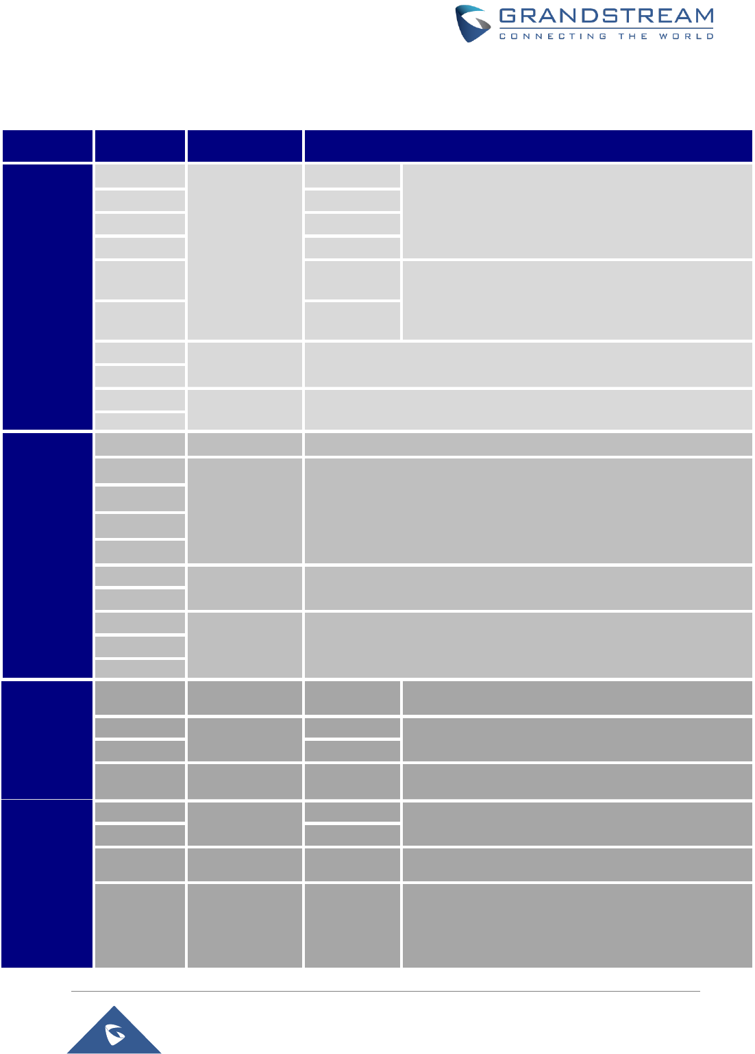
GDS3705 Wiring Connection
Table 4: GDS3705 Wiring Connection
Jack
Signal
Function
Note
J2 (Basic)
3.81mm
TX+
Ethernet
PoE 802.3af
Class 3, 12.95W
Orange / White
Data
TX-
Orange
RX+
Green / White
RX-
Green
PoE_SP2
Blue +
Blue/White
Please twist these two wires together and connect to SP1,
SP2 respectively even the PoE NOT used.
PoE_SP1
Brown +
Brown/White
RS485_B
RS485
RS485_A
GND
Power Supply
DC 12V, 1A Minimum
12V
J3
(Advanced)
3.81mm
GND
Alarm GND
ALARM1_IN+
Alarm In
Vin<15V
ALARM1_IN-
ALARM2_IN+
ALARM2_IN-
NO1
Alarm Out
Relay: 30VDC/2A; 125VAC/0.5A
COM1
NO2
Electric Lock
For "Fail Secure" (Locked when Power Lost) Strike, connect COM2 & NO2.
For "Fail Safe" (Open when No Power) Magnetic Lock, connect COM2 & NC2.
Relay: 30VDC/2A; 125VAC/0.5A
COM2
NC2
J4 (Special)
2.0mm
GND
Wiegand Power
GND
Black
Both Input and Output MUST be connected
WG_D1_OUT
Wiegand Output
Signal
Orange
GDS3705 function as Output of Card Reader, Connect Pin 1,
2, 3
WG_D0_OUT
Brown
LED
Wiegand Output
LED Signal
Blue
For External Card Reader; Or GDS3705 as Receiver Only
WG_D1_IN
Wiegand Input
Signal
White
For External Card Reader
Connect Pin 1,4,5,6,7,8
WG_D0_IN
Green
BEEP
Wiegand Output
BEEP Signal
Yellow
For External Reader Only
5V
Wiegand Power
Output
Red
For External Card Reader Only.
12VDC powered External Card Reader must use own power
source, can NOT use this Pin.
P a g e | 18
GDS3705 User Manual
Version 1.0.0.20
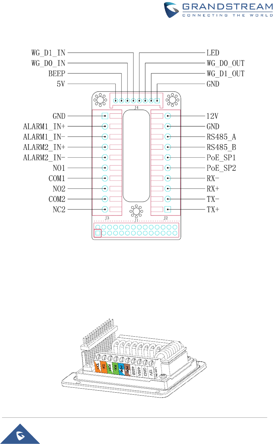
GDS3705 Back Cover Connections
Figure 4: GDS3705 Back Cover Connections
Connection Example
To connect the GDS either by using PoE or PSU follow steps below:
• Open the Back-Cover Board of the GDS3705 which should look like following figure.
Figure 5: GDS3705 Back Cover
P a g e | 19
GDS3705 User Manual
Version 1.0.0.20
Power GDS3705 using PoE
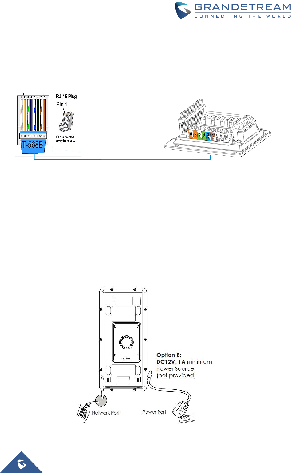
• Cut into the plastic sheath of your Ethernet cable, then Unwind and pair as shown below.
Use the TIA/EIA 568-B standard, which define pin-outs for using Unshielded Twisted Pair cable and
RJ-45 connectors for Ethernet connectivity.
Figure 6: Connection Example
• Connect each wire of the cable to its associate on the Back Cover of the GDS3705 to power the
unit using PoE.
Power GDS3705 using PSU
• To power the unit using PSU, use a multimeter to detect the polarity of your Power Supply, then
connect GND to negative pole and 12V to positive pole of the PSU.
Note: If the user doesn’t have PoE switch, there is no need to connect the Blue and Brown wires to the
GDS3705 since these wires are used to power the unit via Ethernet.
Figure 7: Powering the GDS3705
P a g e | 20
GDS3705 User Manual
Version 1.0.0.20
GETTING TO KNOW GDS3705
The GDS3705 has an embedded Web server to respond to HTTP/HTTPS GET/POST requests. Embedded
HTML pages allow users to configure the GDS3705 through all available Web browsers in the internet.
Connecting GDS3705 to Network with DHCP Server
The GDS3705 by default has a DHCP client enabled, it will automatically get IP address from DHCP server.
Windows Platform
Two ways exist for Windows users to get access to the GDS3705:
UPnP
By default, the GDS3705 has the UPnP feature turned ON. For customers using Windows network with
UPnP turned on (most SOHO routers support UPnP), it is very easy to access the GDS3705:
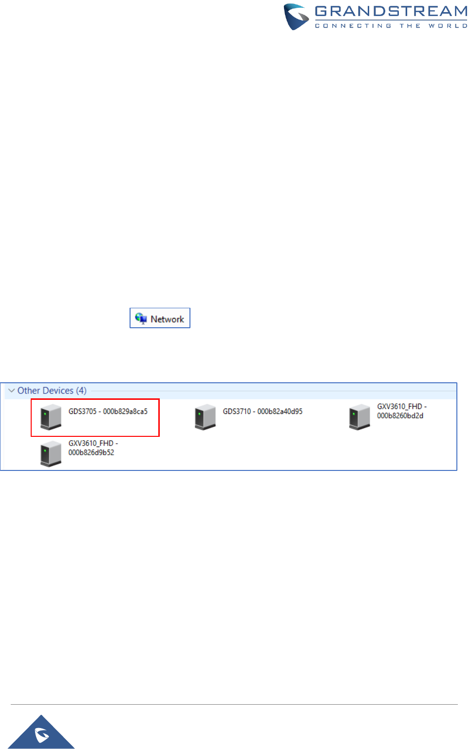
1. Find the “Network” icon on the windows Desktop.
2. Click the icon to get into the “Network”, the GDS3705s will list as “Other Devices” shown like below.
Refresh the pages if nothing displayed. Otherwise, the UPnP may not be active in the network.
Figure 8: Detecting GDS3705 via UPnP
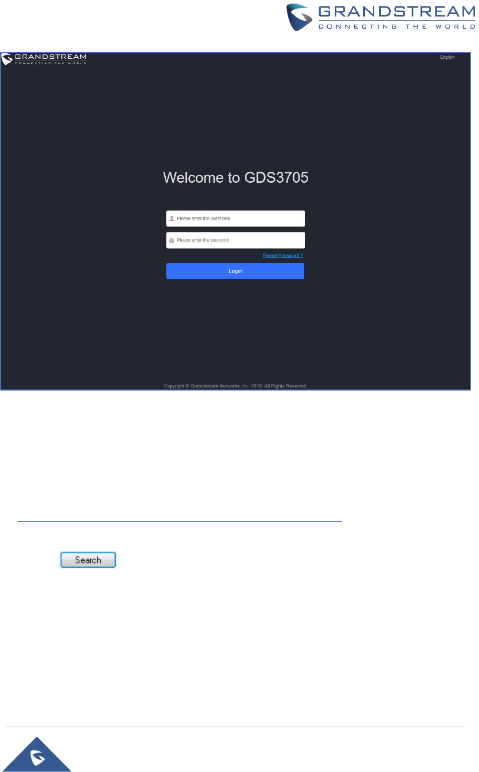
3. Click on the displayed icon of related GDS3705, the default browser (e.g.: Internet Explorer, Firefox
or Chrome) will open and connect directly to the login webpage.
P a g e | 21
GDS3705 User Manual
Version 1.0.0.20
Figure 9: GDS3705 Login Page
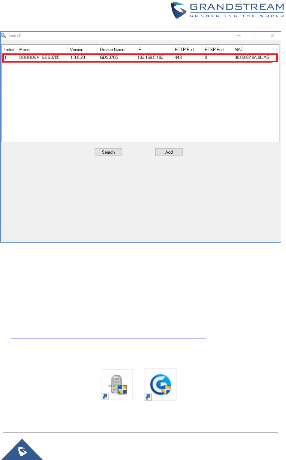
GS Search
GS search is a program that is used to detect and capture the IP address of Grandstream devices. Below
are instructions for using the “GS Search” utility tool:
1. Download the GS Search utility tool from Grandstream website using the following link:
http://www.grandstream.com/sites/default/files/Resources/GS_Search.zip
2. Double click on the downloaded file and the search window will appear.
3. Click on button to start the discovery for Grandstream devices.
4. The detected devices will appear in the output field like below.
P a g e | 22
GDS3705 User Manual
Version 1.0.0.20
Figure 10: GS Search Discovery
5. Double click on a device to access its webGUI.
GDS Manager Utility Tool
User can know the IP address assigned to the GDS3705 from DHCP server log or using the Grandstream
GDS Manager after installing this free utility tool provided by Grandstream. User can find instructions below,
for using “GDS Manager” utility tool:
1. Download the GDS Manager utility tool from Grandstream website using the following link:
http://www.grandstream.com/sites/default/files/Resources/gdsmanager.zip
2. Install and run the Grandstream GDS Manager, a client/server architecture application, the server
should be running first, then GDSManager (client) later:

P a g e | 23
GDS3705 User Manual
Version 1.0.0.20
3. On the GDS Manager access to Device Search and Click on the button to start device
detection
4. The detected devices will appear in the output field like below:
Figure 11: GDS3705 Detection using GDS Manager
5. Double click the column of the detected GDS3705, the browser will automatically open and show the
device’s web configuration page.
6. Enter the administrator user name and password to access the Web Configuration Interface, the default
admin username is “admin” and the default random password can be found at the sticker on the
GDS3705.
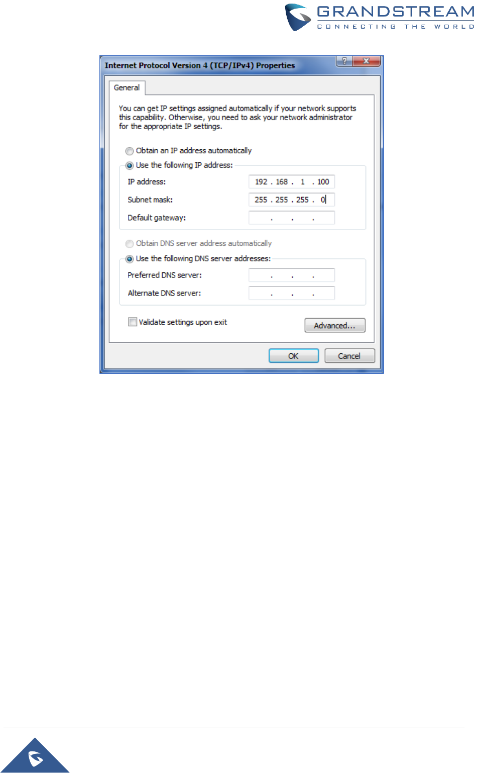
Connect to the GDS3705 using Static IP
If there is no DHCP server in the network, or the GDS3705 does not get IP from DHCP server, user can
connect the GDS3705 to a computer directly, using static IP to configure the GDS3705.
1. The default IP, if no DHCP server, or DHCP request times out (after 3 minutes), is 192.168.1.168
2. Connect the Ethernet cable from GDS3705 to the computer network port directly.
3. Configure the computer using Static IP: 192.168.1.XXX (1<XXX<255, except for 168) and configure
the “Subnet mask” to “255.255.255.0”. Leave the “Default Gateway” to “Blank” like below:
P a g e | 24
GDS3705 User Manual
Version 1.0.0.20
Figure 12: Static IP on Windows
4. Power on the GDS3705, using PoE injector or external DC power.
5. Enter 192.168.1.168 in the address bar of the browser, log in to the device with admin credentials. the
default admin username is “admin” and the default random password can be found at the sticker on
the GDS3705.

P a g e | 25
GDS3705 User Manual
Version 1.0.0.20
GDS3705 APPLICATION SCENARIOS
The GDS3705 Door System can be used in different scenarios.
Peering Mode without SIP Server
For environment like remote warehouse/storage, grocery store, small (take-out) restaurants, just using
static IP with PoE switch to form a LAN, using Grandstream’s audio phone GXP21XX/17XX/16XX series,
the GDS3705 will meet your very basic intercom, and open-door requirements.
This is the solution to upgrade the traditional analogue Intercom system. All you need is a Power source,
Switch or PoE Switch and Grandstream GXP21XX/17XX/16XX audio phones.
The equipment list can be found below:
• GDS3705
• GXP21XX/17XX/16XX
• PoE Switch with related Cat5e/Cat6 wiring
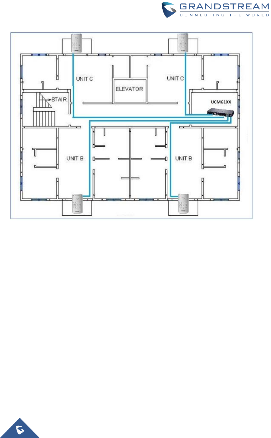
Peering using SIP Server (UCM6XXX)
For large deployment, multiple GDS3705 units might be required, peered connection will not work in such
case due to multiple connections. Such scenarios require an IPPBX or a SIP Proxy to accomplish the tasks.
If remote access is required, a router with internet access should be added to below needed equipment list:
• Several GDS3705
• UCM6XXX or another SIP Server
• GXP21XX/17XX/16XX audio Phones
• PoE Switch with related Cat5e/Cat6 wiring
• Electronic Lock
P a g e | 26
GDS3705 User Manual
Version 1.0.0.20
Figure 13: Peering GDS3705 with UCM6XXX
P a g e | 27
GDS3705 User Manual
Version 1.0.0.20
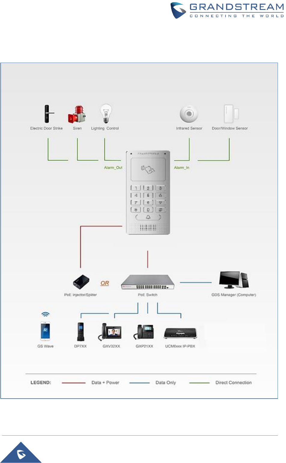
GDS3705 PERIPHERAL CONNECTIONS
Below is the illustration of GDS3705 peripheral connections for related applications.
Figure 14: Peripheral Connections for GDS3705
P a g e | 28
GDS3705 User Manual
Version 1.0.0.20
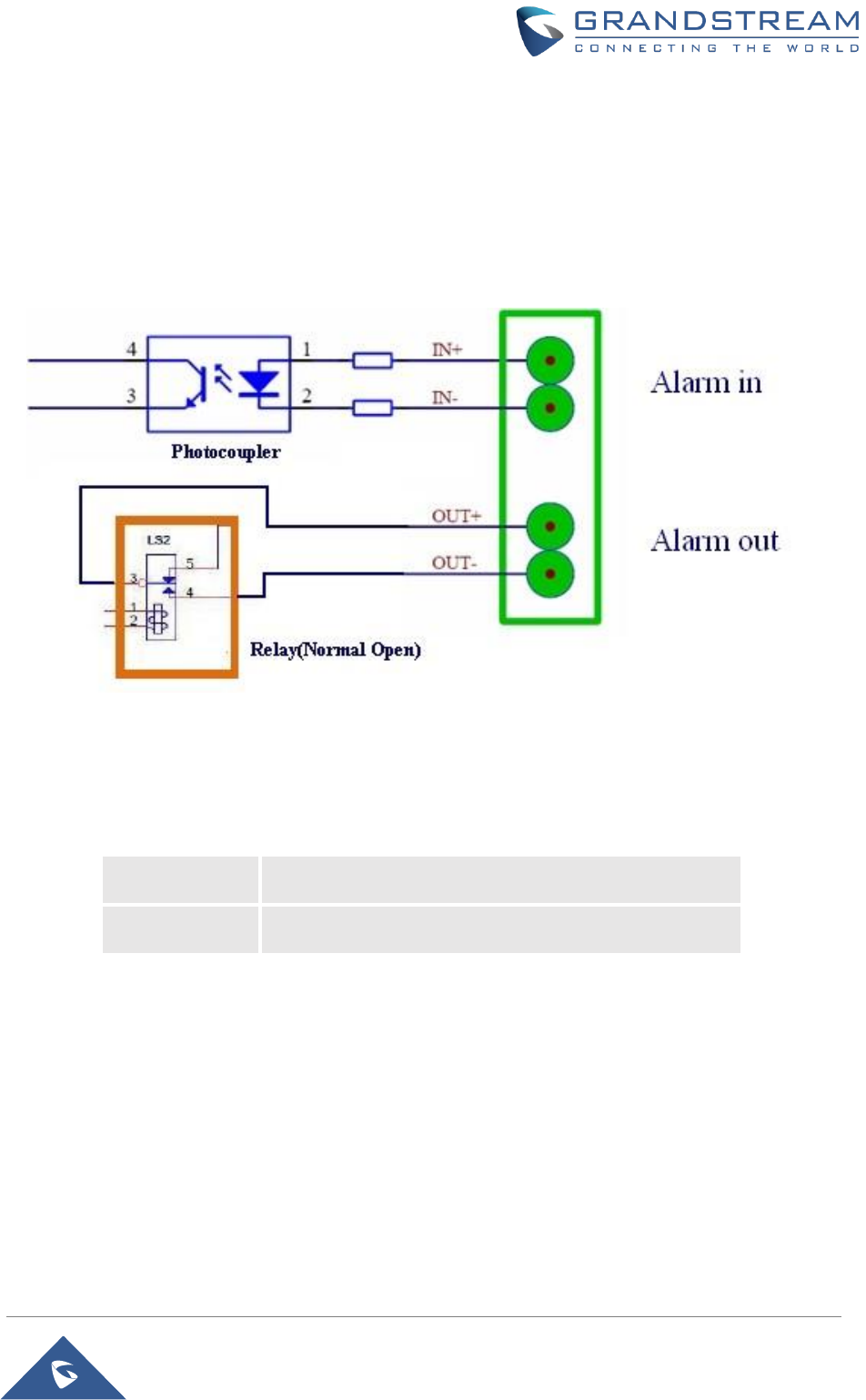
Alarm IN/OUT
Alarm_In could use any 3rd party Sensors (like IR Motion Sensor).
Alarm_Out device could use 3rd party Siren, Strobe Light, or Electric Door Striker, etc.
The figure below shows illustration of the Circuit for Alarm_In and Alarm_Out.
Figure 15: Alarm_In/Out Circuit for GDS3705
Notes:
• The Alarm_In and Alarm_Out circuit for the GDS3705 should meet the following requirement:
Alarm Input
3V<Vin<15V, PINs (1.02KΩ)
Alarm Output
125VAC/0.5A, 30VDC/2A, Normal Open, PINs
• The Alarm_In circuit, if there is any voltage change between 3V and 15V, as specified in the table
above, the GDS3705 Alarm_In port will detect it and trigger the action and event.
• Higher voltage and wrong polarity connection are prohibited because this will damage the devices.
P a g e | 29
GDS3705 User Manual
Version 1.0.0.20
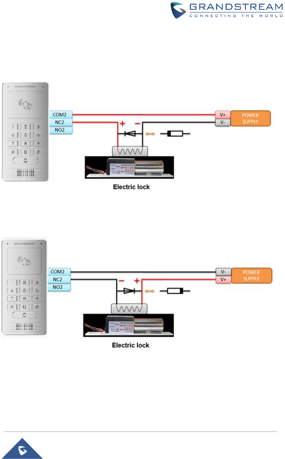
Protection Diode
When connecting the GDS3705 to a door strike it is recommended to set an EMF protection diode in reverse
polarity for a secure use, below examples of deployment for the protection diode.
Figure 16: Protection Diode - Example 1
The reverse EMF protection diode must always be installed in reverse polarity across the door strike.
Figure 17: Protection Diode - Example 2
Connection Examples
Below examples, show how to use wiring on the back cover of the GDS3705 to connect with external
devices. The “NO” (Normal Open) model strike is used as example, “NC” (Normal Closed) should be similar
and users need to decide which model (NO or NC) to be used on the door.
P a g e | 30
GDS3705 User Manual
Version 1.0.0.20
Wiring Sample using 3rd Party Power Supply
Figure 18: 3rd party Power Supply Wiring Sample
Wiring Sample using Power Supply for both GDS3705 and Electric Strike
Figure 19: Power Supply used for both GDS3705 and Electric Strike
P a g e | 31
GDS3705 User Manual
Version 1.0.0.20
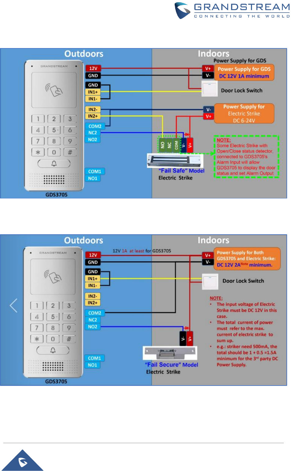
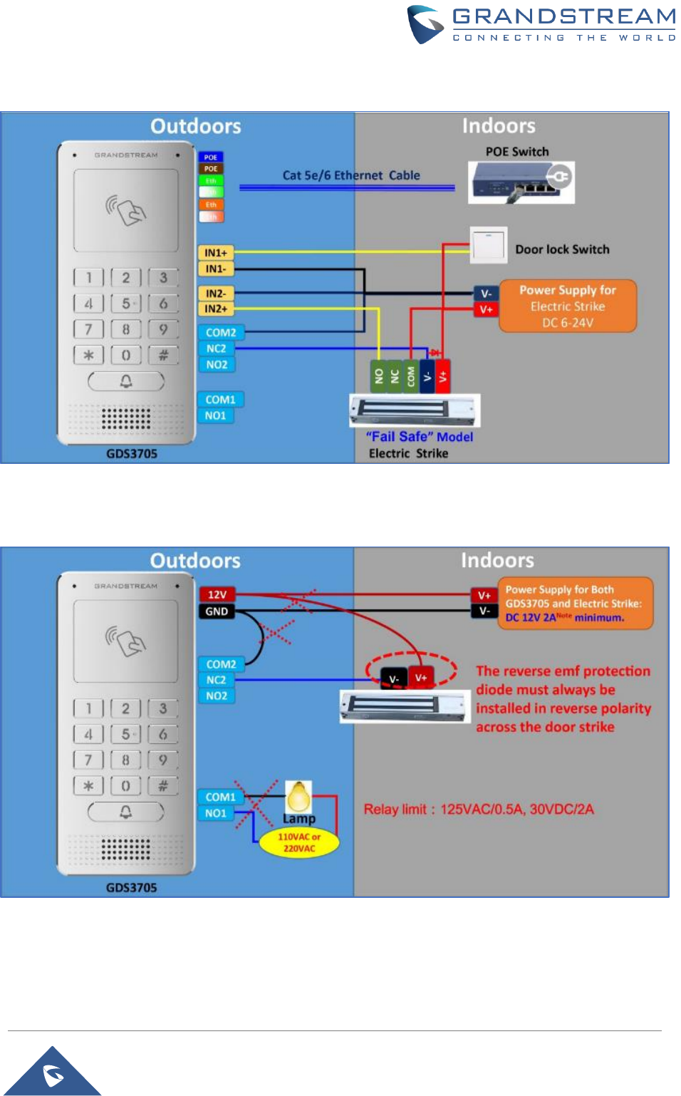
Wiring Sample using PoE to power GDS3705 and 3rd Party Power Supply for Electric Strike
Figure 20: Wiring Sample using PoE to power GDS3705 and 3rd party Power Supply for Electric Strike
Warning: The following example should be avoided when powering the electric strike.
Figure 21: Example to Avoid when Powering the Electric Strike
P a g e | 32
GDS3705 User Manual
Version 1.0.0.20
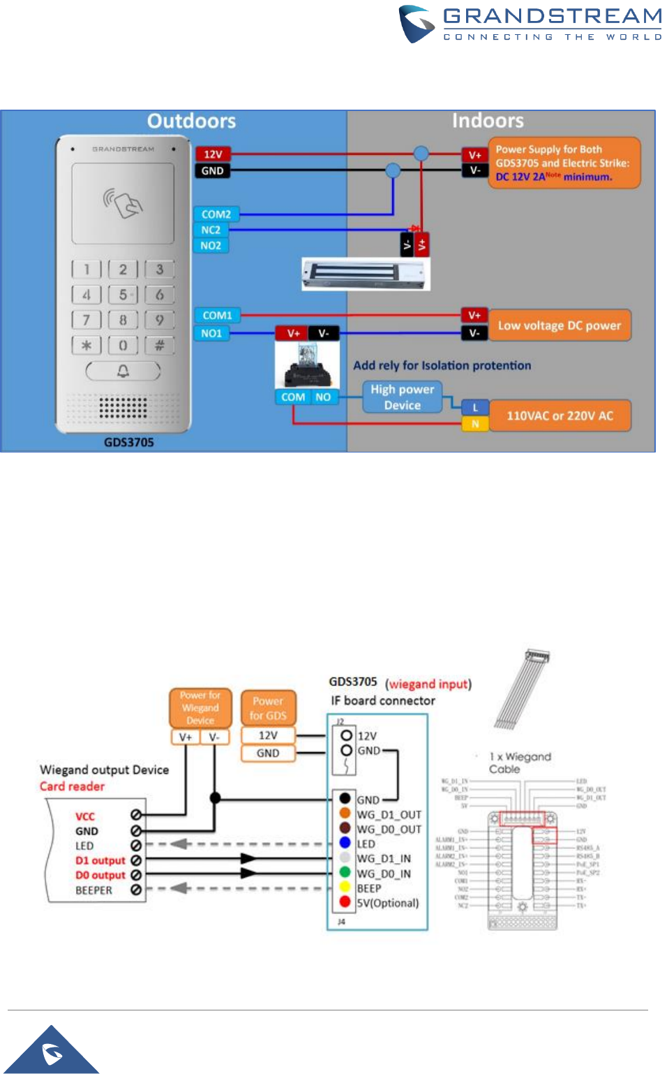
Good Wiring Sample for Electric Strike and High-Power Device
Figure 22: Electric Strike and High-Power Device Example
Wiegand Module Wiring Examples
GDS3705 package is shipped with one Wiegand cable for Input/Output Wiegand connections. The following
examples shows how to connect the Wiegand Input/Output devices to the GDS3705.
Input example with 3rd party power supply for Wiegand device
Figure 23: Wiegand Input Example with 3rd party Power Supply
P a g e | 33
GDS3705 User Manual
Version 1.0.0.20
Make sure to connect the GND of the Wiegand device and the GDS3705 Wiegand port.
For Wiegand input mode, LED and Beep pins require that the Wiegand device support those interfaces.
These two pins will not affect the Wiegand bus when not connected.
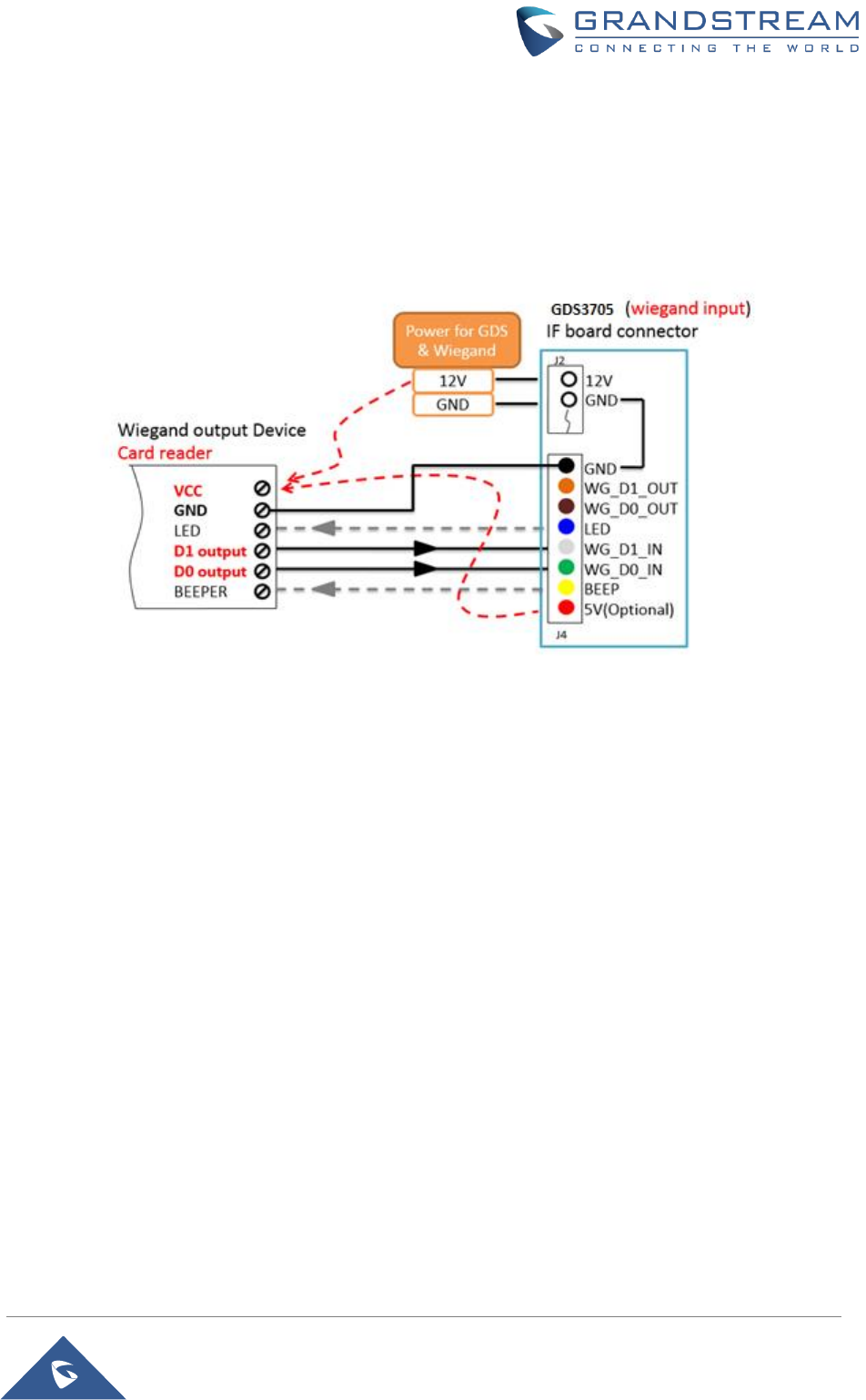
Input example with power supply for both GDS3705 and Wiegand device
Figure 24: Wiegand Input Example with Power Supply for GDS3705 and Wiegand Device
If power source is 12VDC, Wiegand device can share same power source of GDS3705. However, users
need to check the max power consumption and the max capability of the power source.
If Wiegand device is using 5VDC, GDS3705 Wiegand port can provide 5VDC with max 500mA to power up
Wiegand device.
P a g e | 34
GDS3705 User Manual
Version 1.0.0.20
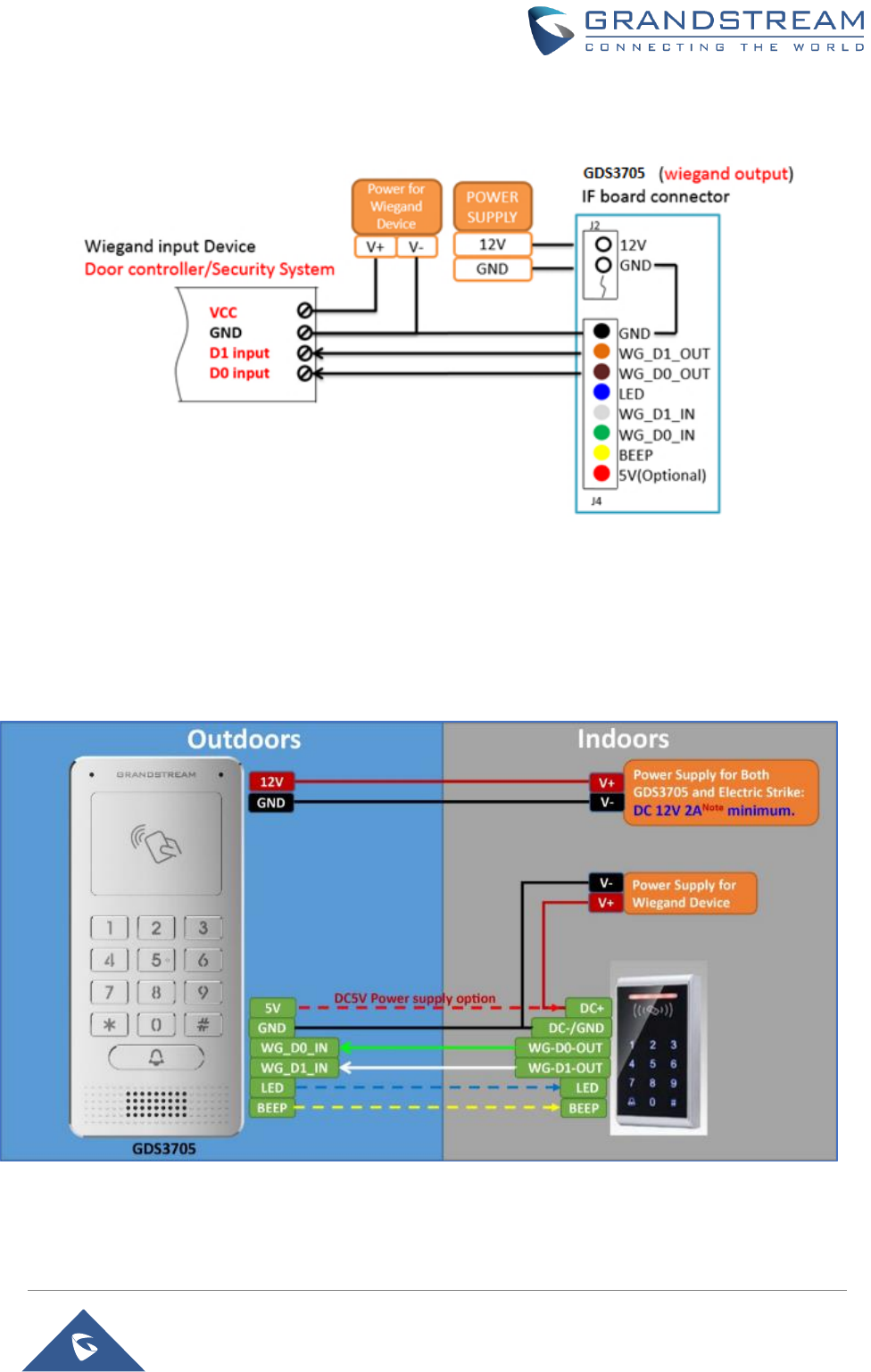
Output example with 3rd party power supply for Wiegand device
Figure 25: Wiegand Output Wiring Example
When the Wiegand output of the GDS3705 is connected, it acts as the signal receiver of the 3rd party
Wiegand device, connecting to door controller. The major wiring is GND, D0, and D1. Because usually the
door controller will consume big current and power, the power supply should be separated.
Wiegand RFID Card Reader Example
Figure 26: Wiegand RFID Card Reader Example
P a g e | 35
GDS3705 User Manual
Version 1.0.0.20
GDS3705 HOME WEB PAGE
• Once the IP address of the GDS3705 is entered on the user browser, the login web page will pop
up allowing user to configure the GDS3705 parameters.
• When clicking on the “Language” drop down, supported languages will be displayed as shown in
Figure below. Click to select the related webpage display language.
Figure 27: Change Language Page
Note: Current firmware supports only English (default) and simplified Chinese.
P a g e | 36
GDS3705 User Manual
Version 1.0.0.20
GDS3705 SETTINGS
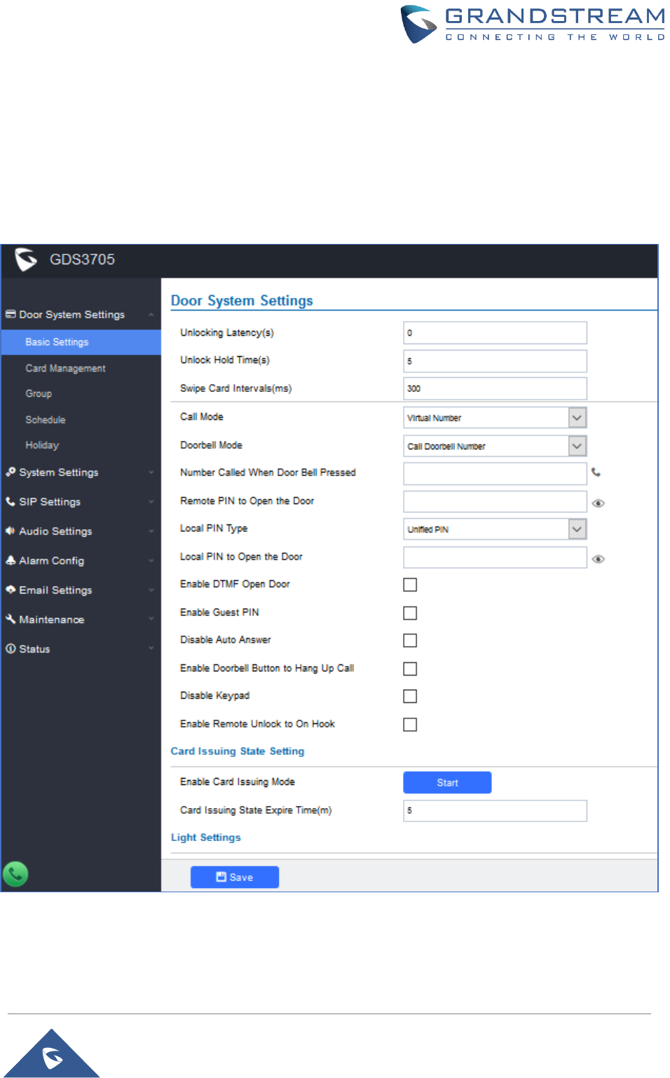
Door System Settings
Users can configure system operations parameters, like input PIN for the door and manage users’ settings.
Basic Settings
Figure 28: Door System Settings Page

P a g e | 37
GDS3705 User Manual
Version 1.0.0.20
Table 5: Door System Settings
Unlocking Latency(s)
Configures the time delay in second for the electronic lock to be triggered
(default value is 0 seconds).
Unlock Hold Time(s)
Configures the lock holding time, in seconds (default value is 5 seconds).
Swipe Card Intervals(ms)
Defines the interval in ms to swipe consecutive RFID cards. The range
should be between 0ms and 2000ms.
Call Mode
Chooses whether to make call to the SIP number or Virtual Number when
dialing from the GDS3705 keypad.
Doorbell Mode
Configures the action to be taken when the doorbell is pressed, three
options are available:
• Call Doorbell Number: when Doorbell is pressed, a call will be
made to the “Number Called When Door Bell Pressed”
• Control Doorbell Output (Digital Output 1): when Door Bell is
pressed electronic lock for Output 1 is opened.
• Both of Above: When selected, both Call Doorbell Number and
Control Doorbell Output options are enabled.
Number Called When Door
Bell Pressed
Configures SIP extension number (SIP Server mode), or IP address with
port number (peering mode), to be called when the Door Bell is pressed:
• SIP Server mode:
- The field can be configured to store multiple one or multiple SIP
extensions, if configured with multiple extensions (ex: 1001, 1002,
1003), separated with “,” the GDS3705 will ring one extension
after the other in a serial mode (GDS will ring each extension by
default 15 seconds, this can be changed on the Ring Timeout).
- When using UCM, users can also configure there a Ring Group
extension (6400 for example) that will ring multiple extensions
simultaneously, or one by one depending on the Ring Group ring
strategy.
- If early medial is enabled on phone side, user can send the PIN
code using the Open-Door button before answering the call (Of
course users can open the door also after answering the call).
When using Parallel Mode via (Ring Group) this will not be
possible since media (for DTMF) won’t be included during the
ringing which is required for door opening.
• Peering mode:
- User should configure multiple IP addresses of phones instead
of SIP extensions, when Door Bell pressed the GDS3705 will ring
the configured IP Addresses in Serial mode.
Note: This field supports a Maximum of 256 characters.

P a g e | 38
GDS3705 User Manual
Version 1.0.0.20
Remote PIN to Open the
Door
Configures PIN code stored in the GDS3705, remote SIP phone needs to
input and match this PIN (the PIN is sent via DTMF while in call) so that
the GDS3705 can open the door.
Local PIN Type
Three Options are available: Private Card PIN, Unified PIN or Card and
Private PIN.
• Private Card PIN: Means every member has a private PIN, the GDS
will record who unlocked the door every time. Users need to enter the
following sequence from the GDS3705 to open the door [*Virtual
Number*Private Door Password#].
Note: When Local PIN type is set to private card PIN, users can also
open the door by swiping their cards.
• Unified PIN: Means all members share a same PIN to unlock the
door. Users need to enter the following sequence from the GDS3705
keypad to open the door [*Local PIN to Open the Door#].
• Card and Private PIN: Means every member needs to swipe his card
and enter his private PIN to open the door using the following
sequence [Swipe the card + *Local PIN to Open the Door#]
Local PIN to Open the
Door
Configures PIN stored in GDS3705, input locally this PIN on the GDS3705
keypad will unlock the door.
This feature needs Private Card PIN, means every member has a private
PIN, the GDS will record who unlocked the door every time. Users need
to enter the following sequence from the GDS3705 to open the door
[*Virtual Number*Private Door Password#].
Note: When local PIN type is set to private card PIN, users can also open
the door by swiping their cards.
Enable DTMF Open Door
When enabled, remote SIP phones can open the door while in call by
entering the remote PIN code configured (the PIN code is sent via DTMF).
Default settings is disabled.
Enable Guest PIN
Enables password entry for guests.
Guest PIN
Configures the password that will be used by guests.
Guest PIN Duration Start
Time
Selects the start time when the Guest PIN start to take effect.
Guest PIN Duration End
Time
Selects the end time when the Guest PIN will stop working.
Disable Auto Answer
If checked, GDS3705 will not answer incoming calls automatically, users
can press any key to answer the call. Default setting in unchecked.
Disable Keypad
When checked the Keypad will be disabled, only Door Bell button can be
pressed.
Enable Remote Unlock to
On Hook
When checked calls will be disconnected automatically 5 seconds after
the remote open door event.
Enable Doorbell Button to
Hang UP Call
When checked the door bell will allow users to hang up the ongoing call.
P a g e | 39
GDS3705 User Manual
Version 1.0.0.20
Enable Card Issuing Mode
Enables RFID card issuing/program into the GDS3705. When selected
sweeping an RFID card into the GDS3705 will add card information into.
[Card Management]
Card issuing State Expire
Time(m)
Card issuing mode will be automatically disabled when timer reached (The
range of value is 1 – 1440, in minutes).
Enable Key Blue Light
When checked, the blue light will be activated when pressing the
GDS3705 Keys.
Enable Blue Light
When enabled, Keypad LED will light based on the configured Start/End
Time. For instance, this option can be used when GDS is deployed on
dark environment, the GDS will be located easily using Keypad LED.
Central Mode
If enabled, Group/Schedule/Holiday can only be synchronized from the
Central (GDS Manager), local configuration will not be allowed.
If disabled, only local configuration from GDS3705 is allowed.
Default setting is “Disabled”.
Key Tone Type
Configures the key tones for the GDS3705.
• Default: Beeps will be played when pressing the GDS3705 keys.
• DTMF: Tones will be played when pressing the GDS3705 keys.
• Mute: No sound will be played when pressing keys.
Wiegand Input Enable
Enable Wiegand Input.
Wiegand Output Enable
Enable Wiegand Output.
Notes: Remote SIP phone needs password (digits 0-9 only, ended with # key) matching the configuration
on the web page to open the door (via DTMF).
GDS3705 support RFID for multiple users to open door, therefore every user has its own PIN. For
environment with 100 users and more, it’s difficult for the GDS3705 to manage all these users and a
separate PC or Server should be involved for such kind of management and monitoring.
In environments with more than 100 users the GDS3705, another possibility would be to set one unified
Local PIN for opening the door for all the users.
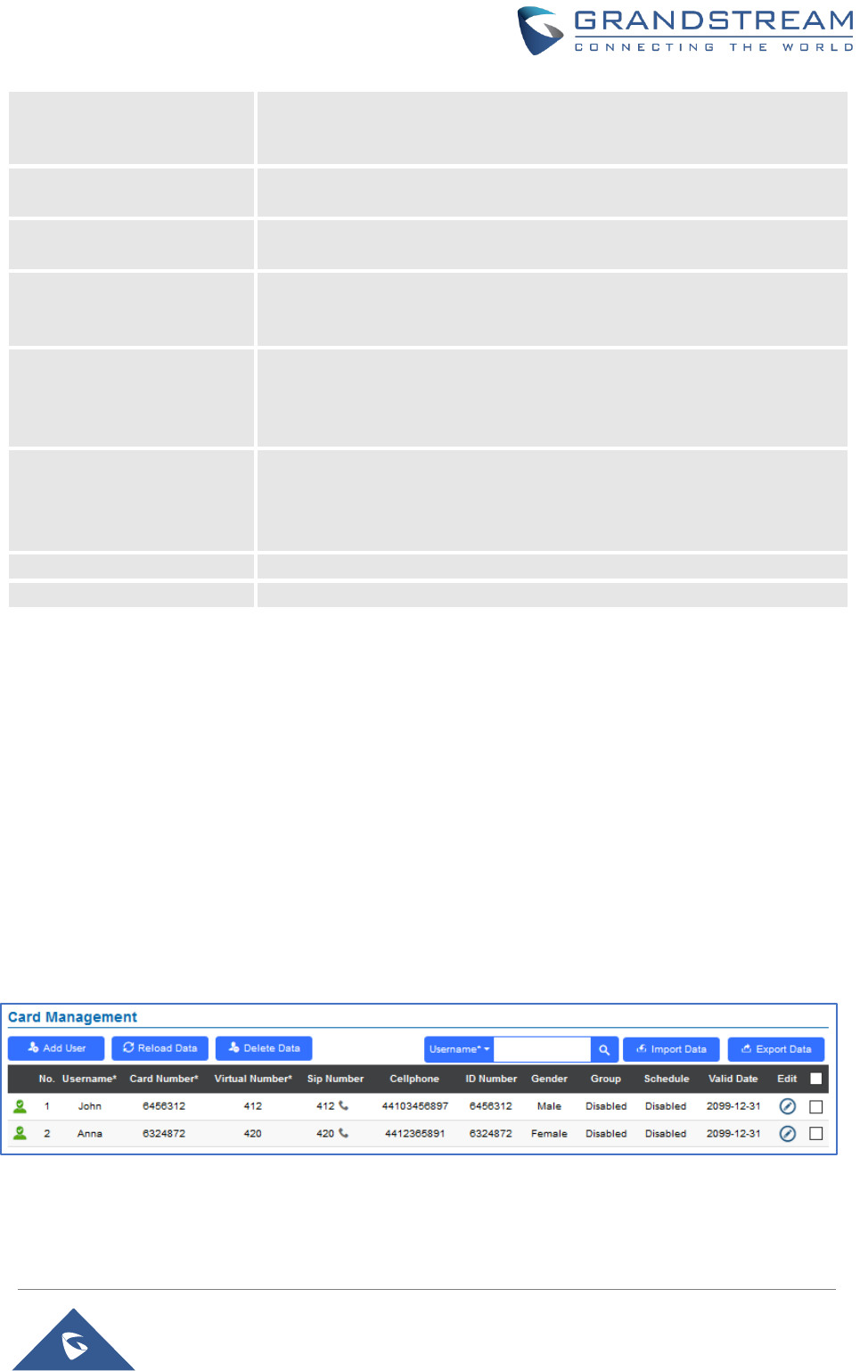
Card Management
This page allows users to add information about RFID cards, two options are possible either add RFID
cards manually or automatically.
Figure 29: Card Management
P a g e | 40
GDS3705 User Manual
Version 1.0.0.20
Notes:
- The GDS3705 can add up to 2000 card user.
- Press or to import / export users’ configuration file, information and
data stored on the GDS3705.
- Use to search for an entry on the Cards list.
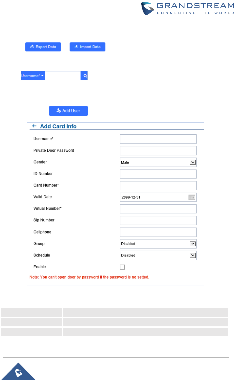
Add Users Manually
To add users, click on , the following page will pop up.
Figure 30: Card Info
Table 6: Card Info
Username
Configures the username to identify the user.
Private Door Password
Specifies a specific password to unlock the door.
Gender
Selects a gender, either Male or Female.
P a g e | 41
GDS3705 User Manual
Version 1.0.0.20
ID Number
Enters an ID number (This number is set by the admin to identify each user
uniquely).
Card Number
Enters the RFID Card number (this is the number written on the RFID card.
When “card issuing mode” is enabled, this filed will be added automatically.
Valid Date
Configures the date of validity of the RFID card.
Virtual Number
When dialing directly from the keypad, the GDS accept only Virtual number
to identify a user, once the Virtual number is typed followed by # key, the
SIP Number will be dialed.
SIP Number
Configures the SIP Number which is mapped with virtual number. Once the
virtual number is dialed the GDS3705 will send an INVITE to the SIP
Number.
Note: The SIP Number can be configured with an extension/phone number
or IP address. Example: 192.168.5.124
Cellphone
Configures cellphone of the user.
Group
Specifies to which group the user will be added.
Schedule
Specifies the schedule that will be assigned to the user.
Enable
Enable/Disable the RFID card.
Notes:
- Group overrides Schedule.
- If Schedule is set as “Disabled” the RFID Card will be accepted when swiped.
Add Users Automatically
If [Enable Card Issuing Mode] is checked, the GDS3705 keypad will start blinking and once an RFID card
is swiped, data stored on the card will be added into the GDS3705 card management page, user can still
edit the entry added automatically by modifying some fields.
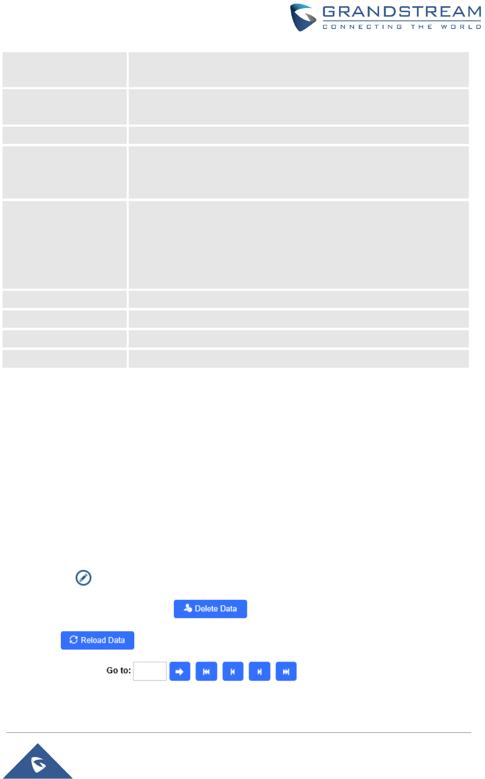
Users Operation
- Click on to edit the entry or show details of the entry.
- Select the entries and click on to delete the selected users.
- Click to refresh the data entered to the GDS3705.
- Users can use to navigate through User Management
pages.
P a g e | 42
GDS3705 User Manual
Version 1.0.0.20
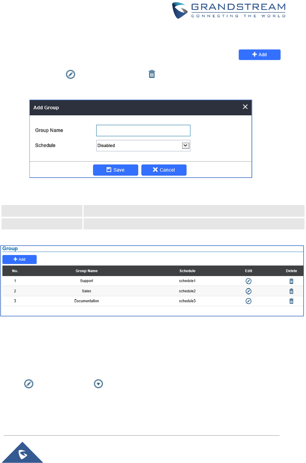
Group
The Group page permits to manage the groups which will contains multiple users, click on
to create new groups or to edit existing groups or to delete the group.
Note: Users can create up to 50 groups.
Figure 31: Add Group
Table 7: Add Group
Group Name
Configures the name to identify the group.
Schedule
Specifies the schedule that will be used by the group.
The following screenshots display the list of the created groups.
Figure 32: Groups List
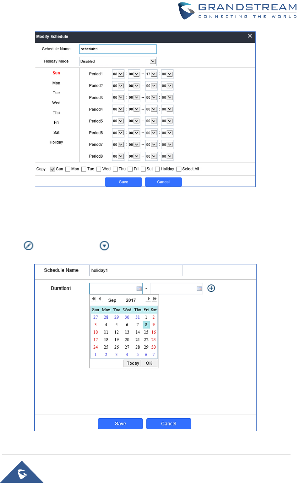
Schedule
The Schedule page allows to manage schedule time frames which will be assigned to the users for door
system usage. Out of the configured time intervals, GDS3705 will not allow users to access.
Click on to edit a schedule or for schedule details.
Note: The GDS3705 supports up to 10 schedules.
P a g e | 43
GDS3705 User Manual
Version 1.0.0.20
Figure 33: Edit Schedule Time
Holiday
The Holiday page allows to manage holidays which will be assigned to the users for door system usage.
Click on to edit the holidays or for holiday details.
Figure 34: Edit Holiday Time
P a g e | 44
GDS3705 User Manual
Version 1.0.0.20
System Settings
This page allows users to configure date and time, network settings as well as access method to the
GDS3705 and password for accessing the Web GUI.
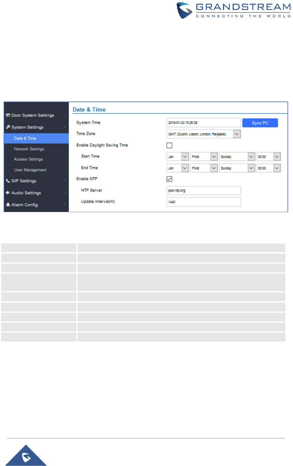
Date & Time Settings
This page allows users to adjust system date and time of the GDS3705.
Figure 35: Date & Time Page
Table 8: Date & Time
System Time
Displays the current system time.
Sync PC
Clicks to synchronize current time with the computer.
Time Zone
Selects from drop down menu the preferred time zone.
Enable Daylight Saving
Time
Enables Daylight Saving Time.
Start time
Selects the Start time of DST.
End Time
Selects DST end time.
Enable NTP
Enables NTP to synchronize device time.
NTP Server
Configures the domain name of NTP server.
Update Interval
Configures the Interval (in minutes) to retrieve updates from the NTP server.
Network Settings
This page allows users to set either a static or DHCP IP address to access the GDS3705.
P a g e | 45
GDS3705 User Manual
Version 1.0.0.20
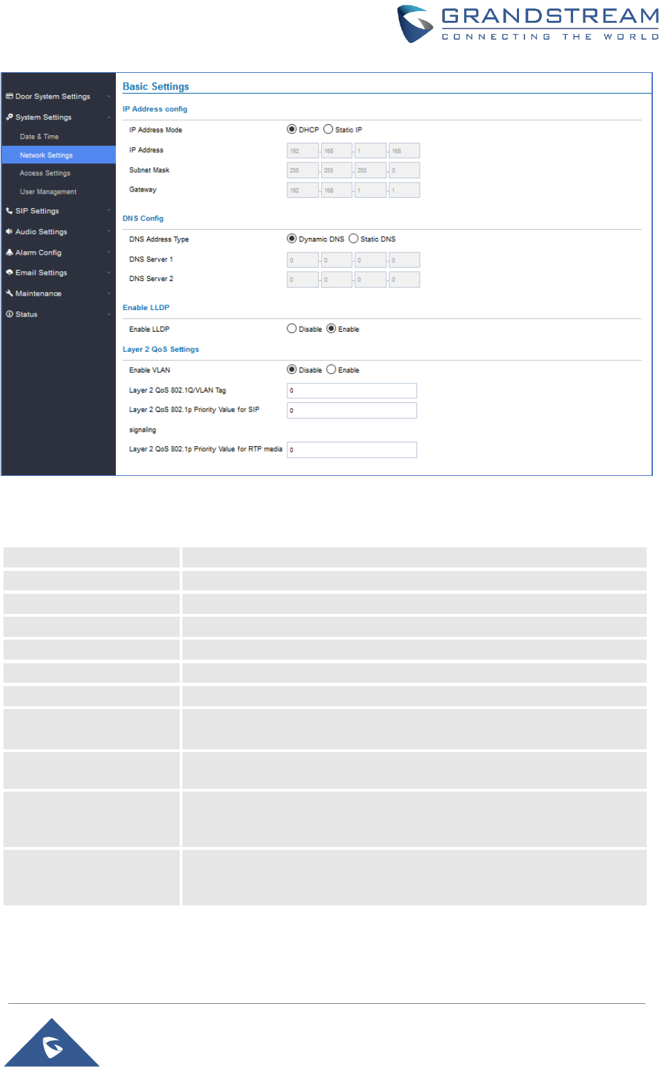
Figure 36: Basic Settings Page
Table 9: Basic Settings
IP Address Mode
Selects DHCP or Static IP. Default DHCP. (Static recommended)
IP Address
Configures the Static IP of the GDS3705.
Subnet Mask
Configures the Associated Subnet Mask.
Gateway
Configures the Gateway IP address.
DNS Address Type
Specifies the DNS type used: Dynamic DNS or Static DNS.
DNS Server 1
Configures DNS Server 1 IP address.
DNS Server 2
Configures DNS Server 2 IP address.
Enable LLDP
Controls the LLDP (Link Layer Discovery Protocol) service. The default
setting is “Enabled”.
Layer 2 QoS
802.1Q/VLAN Tag
Assigns the VLAN Tag of the Layer 2 QoS packets. Default value is 0.
Layer 2 QoS 802.1p
Priority Value for SIP
signaling
Assigns the priority value of the Layer2 QoS packets for SIP signaling.
Default value is 0.
Layer 2 QoS 802.1p
Priority Value for RTP
media
Assigns the priority value of the Layer2 QoS packets for RTP media.
Default value is 0.
P a g e | 46
GDS3705 User Manual
Version 1.0.0.20
Notes:
• If the GDS3705 is behind SOHO (Small Office Home Office) router with port forwarding configured
for remote access, static IP should be used to avoid IP address changes after router reboot.
• TCP port above 5000 is suggested to Port forward HTTP for remote access, due to some ISP would
block port 80 for inbound traffic. For example, change the default HTTP port from 80 to 8088, to
make sure the TCP port will not be blocked.
Access Settings
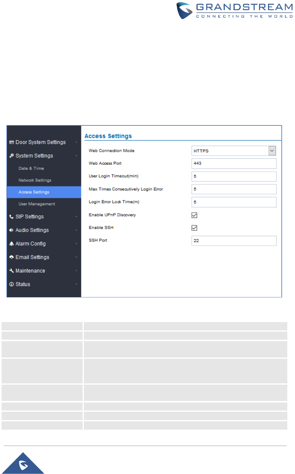
This page configures the GDS3705 access control parameters.
Figure 37: Access Settings Page
Table 10: Access Settings
Web Connection Mode
Selects the access mode to the webGUI either HTTP or HTTPS.
Web Access Port
Specifies the TCP port for Web Access, default 443.
User Login Timeout(min)
If no action is made within this time the GDS3705 will logout from the Web
GUI, range is between 3 and 60.
Max Times Consecutively
Login Error
Specifies the allowed login times error limit, if the unsuccessful login
attempts exceed this value, the GDS3705 webGUI will be locked for the
time specified in Login Error Lock Time.
Login Error Lock Time(m)
Specifies how long the GDS3705 is locked before a new login attempt is
allowed.
Enable UPnP Discovery
UPnP (or mDNS) function for local discovery. Default setting is enabled.
Enable SSH
Selects to Enable/Disable SSH access. Default setting is enabled.
SSH Port
Specifies the SSH port. Default setting is 22.
P a g e | 47
GDS3705 User Manual
Version 1.0.0.20
User Management
This page allows users to configure the password for administrator. Since this is a door system which must
be a secure product, the use is only limited to administrator.
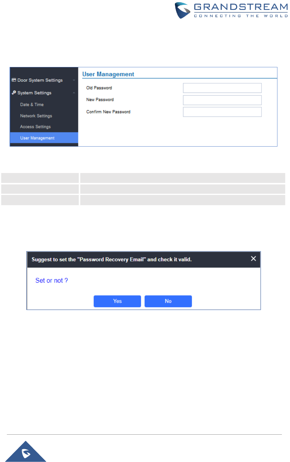
Figure 38: User Management Page
Table 11: User Management
Old Password
Old password must be entered to change new password.
New Password
Fill in the revised new password in this field.
Confirm User Password
Re-enter the new password for verification, must match.
Note:
When trying to change the password, users need to set the “Password Recovery Email” which is a valid
Email account configurable under “Email & FTP Settings Email Settings” to retrieve the email before
the new admin password take effect as displayed on the following screenshot.
Figure 39: Password Recovery Email
SIP Settings
SIP Basic Settings
Basic Settings allow users to configure their SIP account.
P a g e | 48
GDS3705 User Manual
Version 1.0.0.20
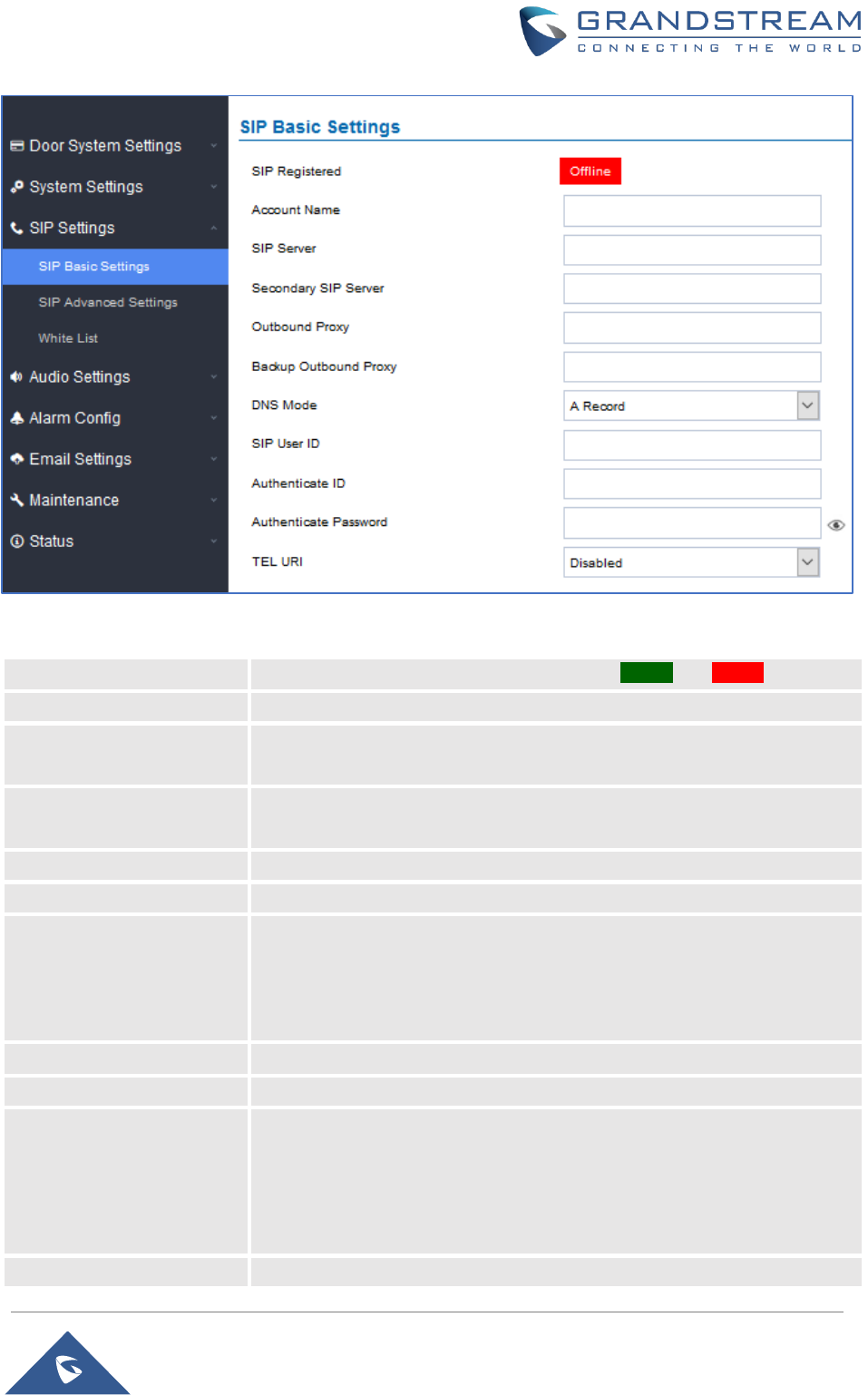
Figure 40: SIP Basic Settings Page
Table 12: SIP Basic Settings
SIP Registered
Displays the SIP registration status. Display “Online” or “Offline”.
Account Name
Configures the SIP account name used for identification.
SIP Server
Configures the FQDN or IP of the SIP server from VoIP service provider or
local IPPBX.
Secondary SIP Server
Configures the FQDN or IP of the Secondary SIP server from VoIP service
provider or local IPPBX.
Outbound Proxy
Configures the IP or FQDN of Outbound proxy server.
Backup Outbound Proxy
Configure the IP or FQDN of Backup Outbound Proxy Server.
DNS Mode
Configure which DNS Mode will be used to translate the SIP Server FQDN
(Default value is A Record):
• A Record.
• SRV.
• NAPTR/SRV.
SIP User ID
Configures the SIP username or telephone number from ITSP.
Authenticate ID
Configures the Authenticate ID used by SIP proxy.
TEL URI
Select “User=Phone” or “Enabled” from the dropdown list.
If the SIP account has an assigned PSTN telephone number, this field
should be set to "User=Phone". Then a "User=Phone" parameter will be
attached to the Request-Line and "TO" header in the SIP request to
indicate the E.164 number. If set to "Enable", "Tel:" will be used instead of
"SIP:" in the SIP request. The default setting is "Disable".
Authenticate Password
Sets the Authenticate password used by SIP proxy.
P a g e | 49
GDS3705 User Manual
Version 1.0.0.20
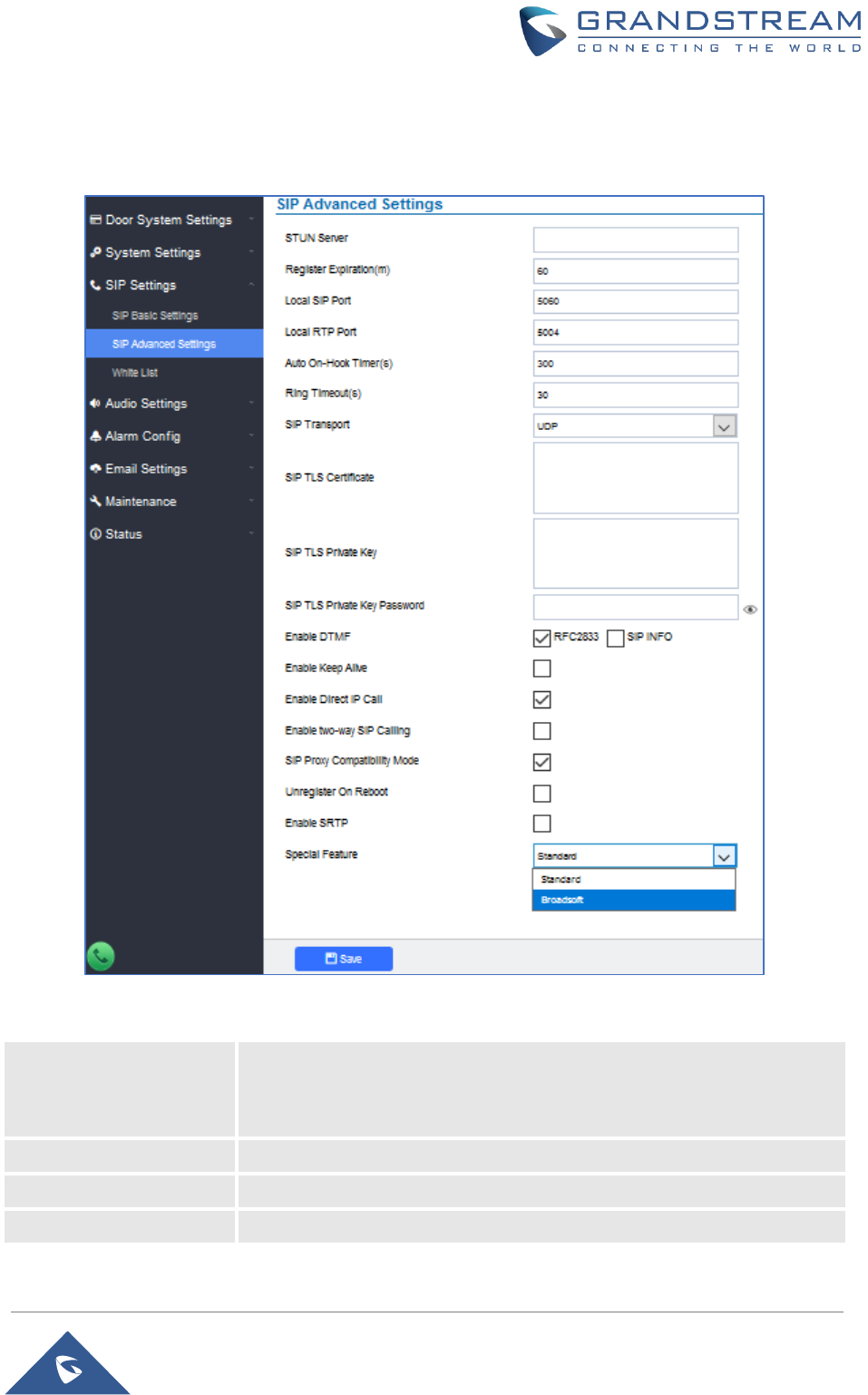
SIP Advanced Settings
This page allows Advanced SIP parameters to be configured.
Figure 41: SIP Advanced Settings Page
Table 13: SIP Advanced Settings
STUN Server
Configures the STUN server FQDN or IP. If the device is behind a non-
symmetric router, STUN server can help to penetrate & resolve NAT
issues.
Register Expiration
Sets the registration expiration time. Default setting is 60 minutes.
Local SIP Port
Sets the local SIP port. Default setting is 5060.
Local RTP Port
Sets the local RTP port for media. Default setting is 5004.

P a g e | 50
GDS3705 User Manual
Version 1.0.0.20
Auto On-Hook Timer
Configures the auto on-hook timer (in seconds) for automatic
disconnecting the SIP call. Default setting is 300.
Ring Timeout(s)
Specifies the Ring timeout, when no reply is returned from the called party
after exceeding this filed, the GDS3705 will hang up the call. The value is
in the range of 0s – 60s. By default; it is “15” seconds.
SIP Transport
Chooses the SIP transport protocol. Default settings is UDP.
SIP TLS Certificate
Copy/Paste the TLS certificate here for encryption.
SIP TLS Private Key
Input private key here for TLS security protection.
SIP TLS Private Key
Password
Specifies the password for SIP TLS private Key.
Enable DTMF
Specifies the mechanism to transmit DTMF digits. There are 2 supported
modes:
• RFC2833 sends DTMF with RTP packet. Users can check the RTP
packet to see the DTMFs sent as well as the number pressed.
• SIP INFO uses SIP INFO to carry DTMF. Default setting is
"RFC2833"
Enable Keep Alive
Checks to help NAT resolution, sending alive packets.
Enable Direct IP Call
Accepts peer-to-peer IP call (over UDP only) without SIP server.
Default is “Enabled”.
Enable two-way SIP
Calling
Allows the user to enable/disable the alarm sound during a SIP call
triggered by doorbell pressing.
SIP Proxy Compatibility
Mode
Enables more proxy compatibility with cost of bandwidth, the SIP call will
send audio no matter what.
Unregister on Reboot
Allows the SIP user's registration information to be cleared when the
GDS3705 reboots. The SIP REGISTER message will contain “Expires: 0”
to unbind the connection
Enable SRTP
Enable SRTP mode. By default, it’s disabled.
Special Feature
Configures GDS settings to meet different vendors’ server requirements.
Users can choose from Standard and Broadsoft.
The default setting is “Standard”.
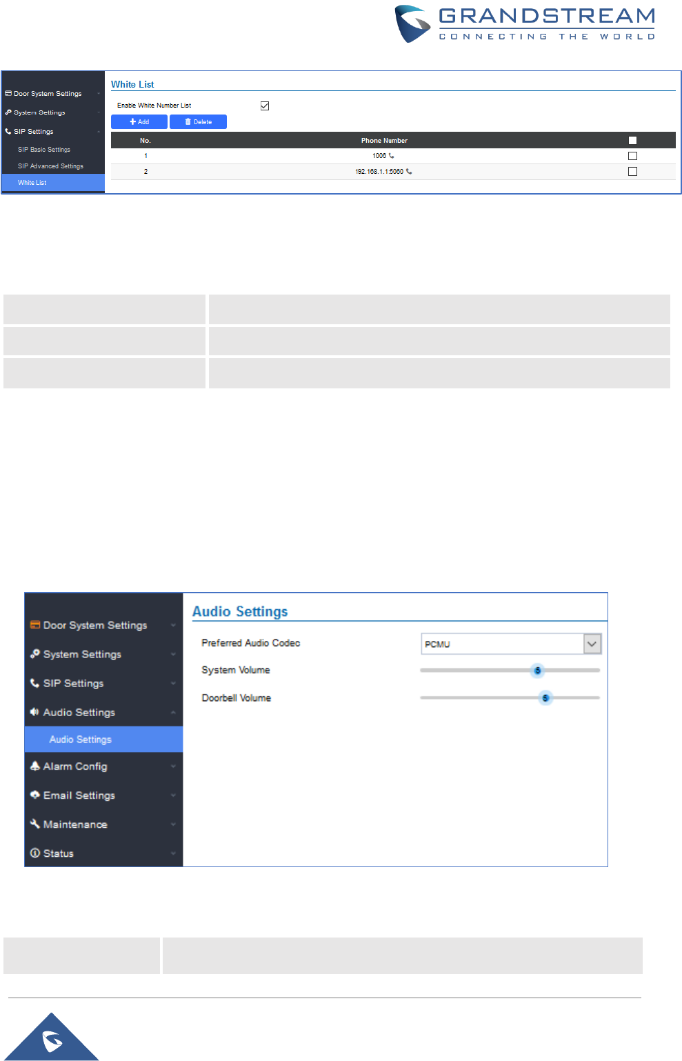
White List
This page allows users to configure the white list, which is a phone number or extension list that can call
the GDS3705. (the call will be automatically answered when calling from a phone set on the white list).
P a g e | 51
GDS3705 User Manual
Version 1.0.0.20
Figure 42: White List Page
The table below gives a brief overview of the options:
Table 14: White List
Enable White Number List
Enables the White List feature.
Add
Adds a new phone number to the white list.
Delete
Deletes a number from the white list.
Note: All whitelisted numbers can open door remotely using PIN Code when calling GDS.
Audio Settings
The audio settings allow users to configure the audio codecs and Volume related settings.
Audio Settings
This page allows users to configure the audio settings.
Figure 43: Audio Settings Page
Table 15: Audio Settings
Preferred Audio
Codec
Configures the audio codec. Three codecs are available:
PCMU, PCMA and G.722.
P a g e | 52
GDS3705 User Manual
Version 1.0.0.20
System Volume
Adjusts the speaker volume connected.
Doorbell Volume
Adjusts the doorbell volume.
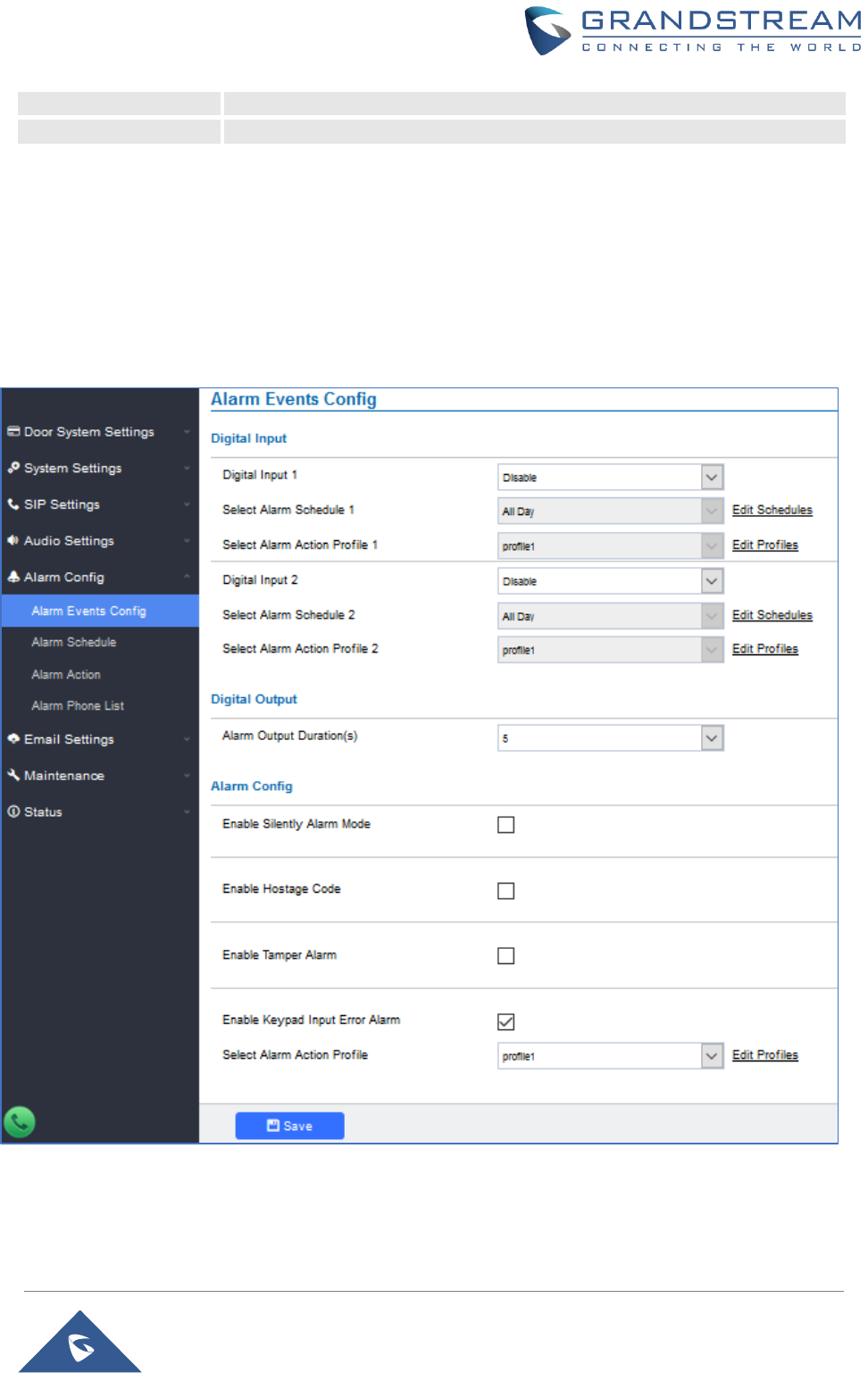
Alarm Config
This page allows users to configure alarm schedule and alarm actions.
Alarm Events Config
This page allows users to configure GDS3705 events to trigger programmed actions within predefined
schedule.
Figure 44: Events Page
Alarm can be triggered by GDS3705 input.
P a g e | 53
GDS3705 User Manual
Version 1.0.0.20
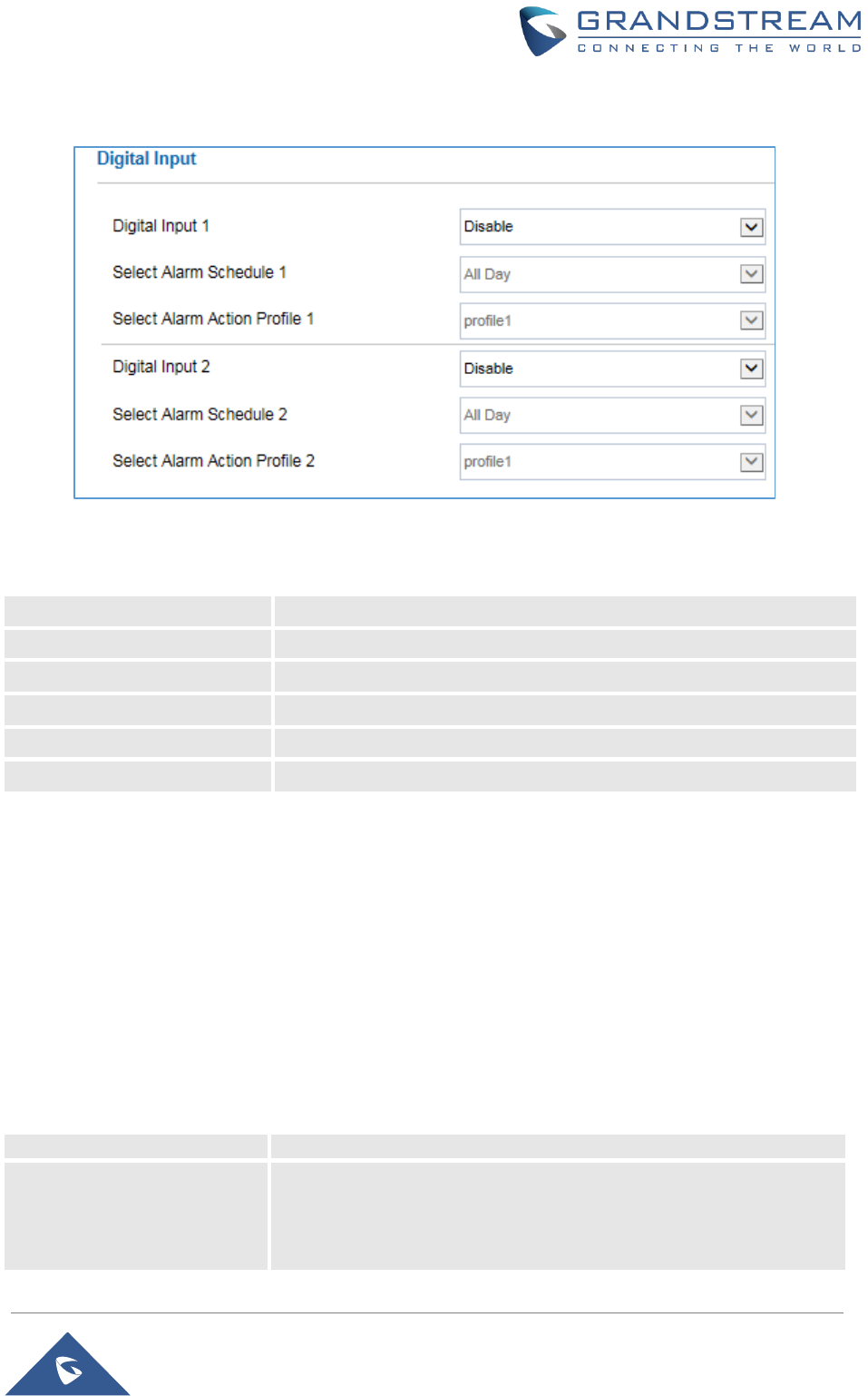
Digital Input
Figure 45: Digital Input
Table 16: Digital Input
Digital Input 1
Selects the Input method (alarm Input or Door Open).
Select Alarm Schedule 1
Selects the predefined Alarm Schedule.
Select Alarm Action Profile 1
Selects the predefined Alarm Action for Profile 1.
Digital Input 2
Selects the Input method (alarm Input or Door Open).
Select Alarm Schedule 2
Selects the predefined Alarm Schedule.
Select Alarm Action Profile 2
Selects the predefined Alarm Action for Profile 2.
Alarm Output
Alarm Output Duration(s) specifies how long the alarm output will take effect. The available values are:
5,10,15,20,25 and 30 seconds.
Silently Alarm Mode
If Silently Alarm Mode is enabled, GDS3705 will disable alarm sound and background light for specified
alarms types (Digital Input) when they are triggered.
Note: This option affects only alarm sound/light, other actions will still be applied.
Table 17: Silently Alarm Mode
Enable Silently Alarm Mode
Enable/Disable silent alarm mode.
Silently Alarm Options
When the silently alarm mode is enabled, users can specify to which
alarm options the silently mode will be applied to.
The available options are: Digital Input, Motion Detection, Tamper
Alarm, and Password Error.

P a g e | 54
GDS3705 User Manual
Version 1.0.0.20
Hostage Code
Hostage password can be used in a critical situation for instance a kidnaping or an emergency, users need
to enter the following sequence to trigger the actions set for the Hostage Mode: “* HostagePassword #”.
Table 18: Hostage Code Alarm
Enable Hostage Code
Enable/Disable the Hostage password mode.
Hostage Code
Configures the password for the hostage mode.
Select Alarm Action Profile
Select the Alarm action to be taken when the hostage password is
typed on the GDS3705 keypad.
Note: No sound alarm will be triggered in this mode.
Tamper Alarm
Tamper alarm is anti-hack from Hardware level. When this option is checked, if the GDS3705 is removed
from the installation board, it will trigger configured alarm actions. There is an embedded mechanism on
the GDS3705 that allows it to detect when the it is removed.
Table 19: Tamper Alarm
Enable Tamper Alarm
When activating this mode, GDS3705 will keep alarming until the alarm
is dismissed.
Select alarm Action Profile
Select the type of alarms actions to be triggered for the tamper alarm
mode.
Keypad Input Error Alarm
Table 20: Keypad Input Error Alarm
Enable Keypad Input Error
Alarm
Enable/Disable the Input Error Alarm, GDS3705 will trigger alarm
actions at every 5 incorrect attempts.
Select Alarm Profile
Select the type of alarms actions to be triggered after 5 incorrect
attempts.
P a g e | 55
GDS3705 User Manual
Version 1.0.0.20
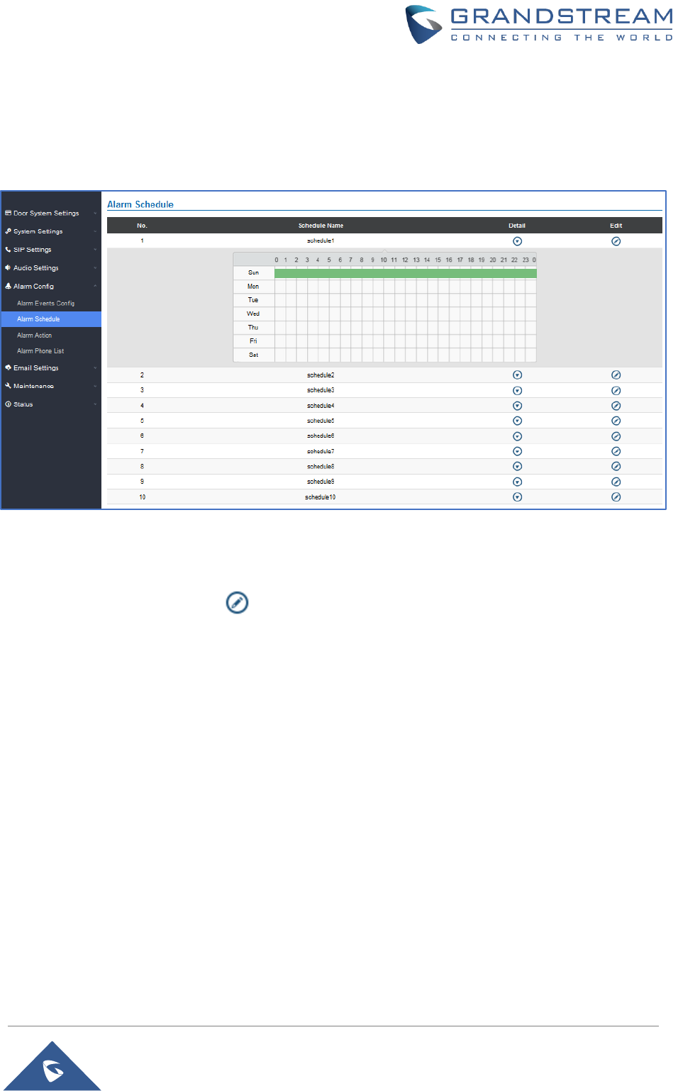
Alarm Schedule
This page specifies the configuration of Alarm Schedule.
Note: Schedule must be configured first to allow the alarm to take the related action.
Figure 46: Alarm Schedule
GDS3705 supports up to 10 alarm schedules to be configured, with time span specified by users. User can
edit the alarm schedule by clicking button. Usually the 24 hours’ span is 00:00 ~ 23:59, which is 24
hours’ format.
Users can copy the configuration to different date during the schedule programming.
P a g e | 56
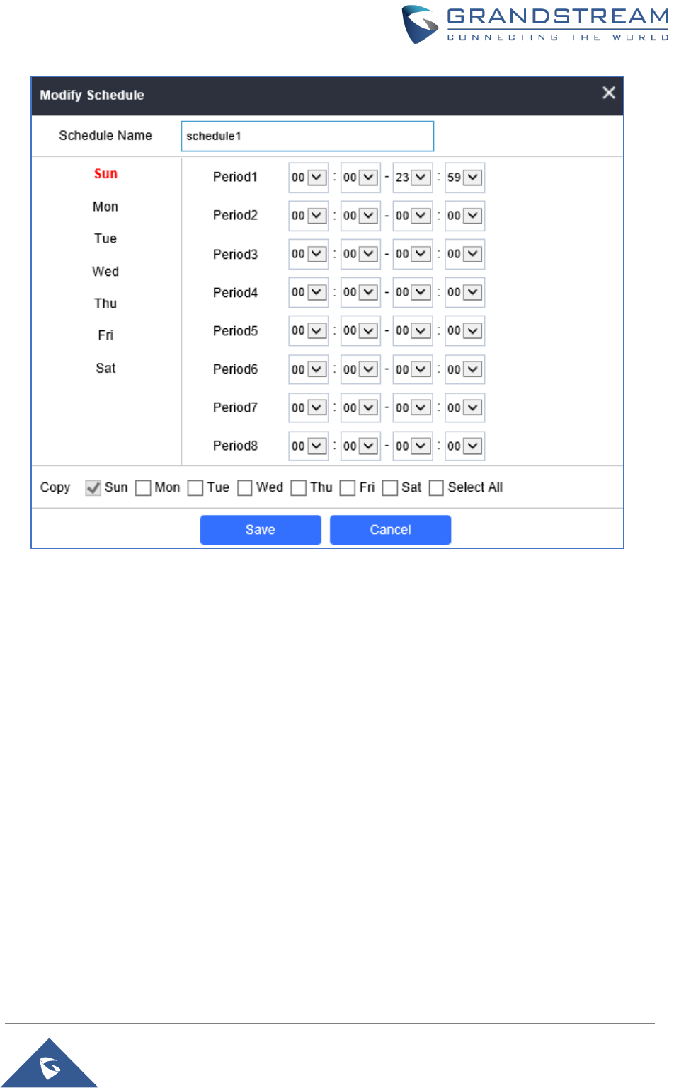
GDS3705 User Manual
Version 1.0.0.20
Figure 47: Edit Schedule
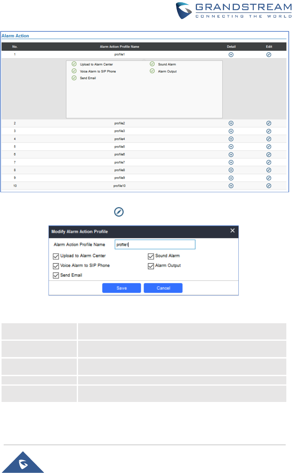
Alarm Action
This page specifies the configuration of Profile used by the Alarm Actions. A Profile is required before the
Alarm Action can take effect.
P a g e | 57
GDS3705 User Manual
Version 1.0.0.20
Figure 48: Alarm Action
User can edit the alarm action by clicking button, the following window will popup.
Figure 49: Edit Alarm Action
Table 21: Alarm Actions
Upload to Alarm Center
If selected, the GDSManager will popup alarm window and sound alarm in
the computer speaker.
Voice Alarm to SIP
Phone
If selected, GDS3705 will call pre-configured phone and will play sound
alarm.
Send Email
If selected, an email with snapshot will be sent to the pre-configured email
destination.
Sound Alarm
If selected, GDS3705 will play alarm audio using built-in speaker.
Alarm Output
If selected, the alarm will be sent to the equipment (for example: Siren)
connected to Alarm Output interface.
P a g e | 58
GDS3705 User Manual
Version 1.0.0.20
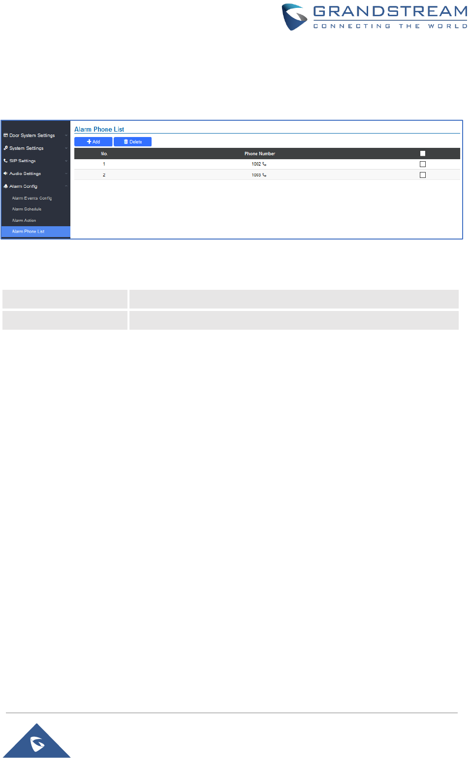
Alarm Phone List
This page allows users to configure the Alarm Phone List, which are phone numbers or extensions list that
the GDS3705 will call out when event is trigged (e.g.: doorbell pressed).
Figure 50: Alarm Phone List
Table 22: Alarm Phone List
Add
Adds new phone number to the alarm list.
Delete
Deletes a number from the phone alarm list.
Once the event is triggered (Motion Detection, Door Bell Pressed…), the GDS3705 will call the first number,
once time out is reached and no answer is returned from the first number, the GDS3705 will try the next
number on the list and so on. Once the remote phone answers the call, an alarm will be played to notify
users that an event is triggered.
Email Settings
This page contains Email Settings.
Email Settings
This page allows users to configure email client to send out an email when the alarm is trigged.
P a g e | 59
GDS3705 User Manual
Version 1.0.0.20
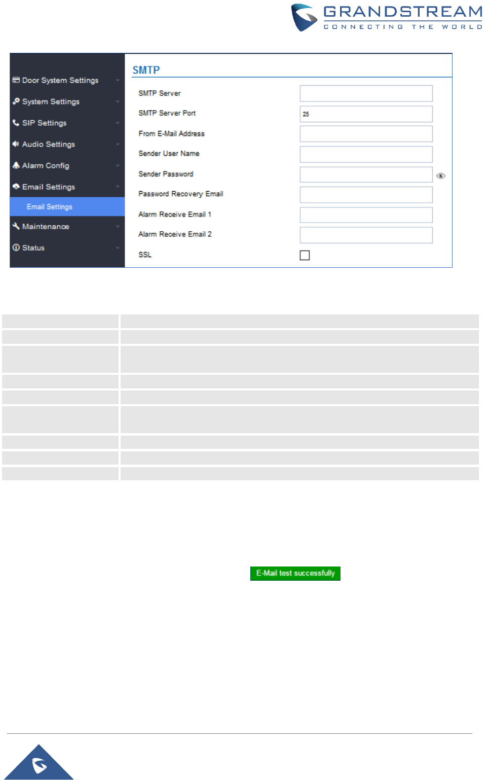
Figure 51: Email Settings - SMTP Page
Table 23: Email Settings - SMTP
SMTP Server
Configures the SMTP Email Server IP or Domain Name.
SMTP Server Port
Specifies the Port number used by server to send email.
From E-mail address
Specifies the email address of alarm email sending from, usually client email
ID.
Sender User Name
Specifies sender’s User ID or account ID in the email system used.
Sender Password
Specifies sender’s password of the email account.
Password Recovery
Email
Specifies Email address used when password forgot and reset required.
Alarm Receive Email 1
Specifies the 1st email address to receive the alarm email.
Alarm Receive Email 2
Specifies the 2nd email address to receive the alarm email.
SSL
Check if the SMTP email server requires SSL.
Notes:
• Click “Save” to save the email configuration information.
• Click “Email Test” after configuration, if settings are correct, a test email will send out and “E-mail test
successfully” message on the top page will appear .
Maintenance Settings
This page shows the GDS3705 Maintenance parameters.
Upgrade
This page contains the upgrade parameters of the GDS3705.
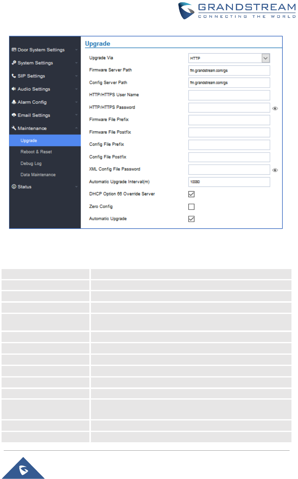
P a g e | 60
GDS3705 User Manual
Version 1.0.0.20
Figure 52: Upgrade Page
Table 24: Upgrade
Upgrade Via
Selects the upgrade method (HTTP, HTTPS).
Firmware Server Path
Configures the IP address or the FQDN of the upgrade server.
Config Server Path
Configures the IP address or the FQDN of the configuration server.
HTTP/HTTPS User Name
User name if needed by remote provisioning HTTP/HTTPS server.
HTTP/HTTPS Password
Password to authenticate with remote provisioning HTTP/HTTPS
server.
Firmware File Prefix
Prefix that will be added when requesting firmware file.
Firmware File Postfix
Postfix that will be added when requesting firmware file.
Config File Prefix
Prefix that will be added when requesting config file.
Config File Postfix
Postfix that will be added when requesting config file.
XML Config File Password
Specifies the password for the configuration file.
Automatic Upgrade Interval
Specifies the upgrade interval in minutes.
DHCP Option 66 Override
Server
Activates DHCP option 66 to override upgrade/config servers.
Zero Config
Enables Zero Config feature for auto provisioning.
Automatic Upgrade
Enables automatic upgrade and provisioning.
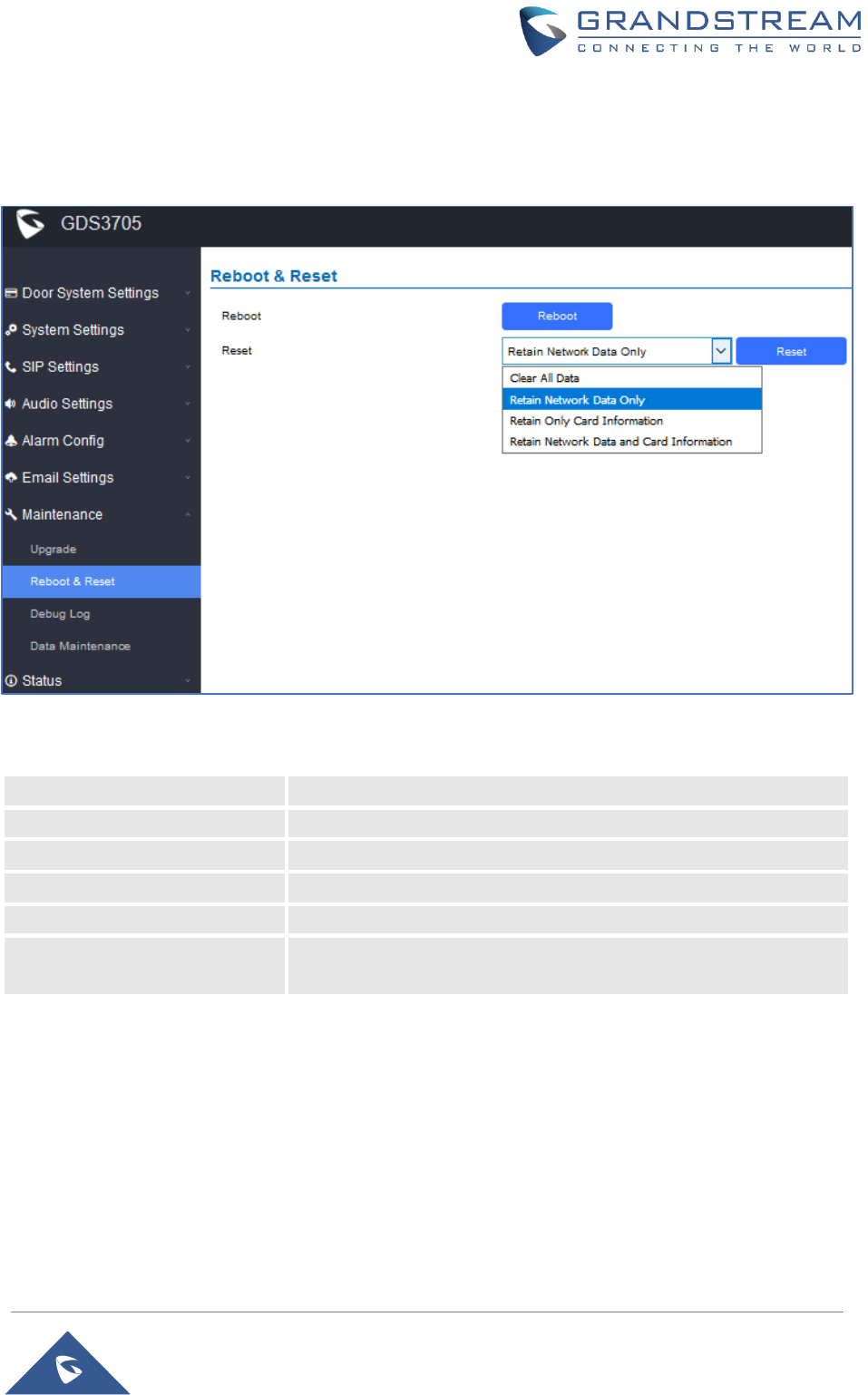
P a g e | 61
GDS3705 User Manual
Version 1.0.0.20
Reboot & Reset
This page allows user to reboot and reset the GDS3705.
Figure 53: Reset & Reboot Page
Table 25: Reset & Reboot
Reboot
When clicked, the GDS3705 will restart (soft reboot).
Reset
There are two options for the reset function.
Clear All Data
All data will be reset, GDS3705 will be set to factory default.
Retain Network Data Only
All data will be erased except for Network data like IP address…
Retain Only Card Information
All data will be erased except for cards information.
Retain Network Data and Card
Information
All data will be erased except for Network Data and Card Information.
Debug Log
This page allows user to configure SYSLOG to collect information to help troubleshooting issues with
GDS3705.
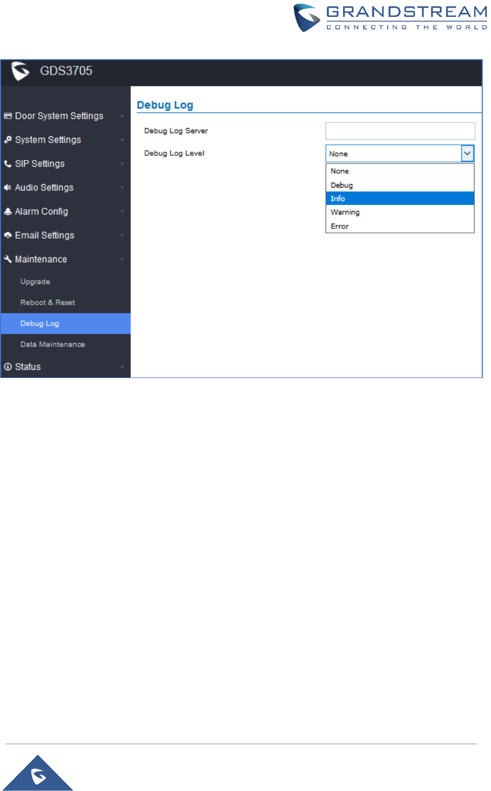
P a g e | 62
GDS3705 User Manual
Version 1.0.0.20
Figure 54: Debug Log Page
Notes:
• Five levels of Debugging are available, None, Debug, Info, Warning, Error.
• Once the Syslog Server and the level entered, press “Save” and then Reboot the GDS3705 to
apply the settings.
Data Maintenance
This page allows users to manage the GDS3705 configuration file by importing / exporting the configuration
files.
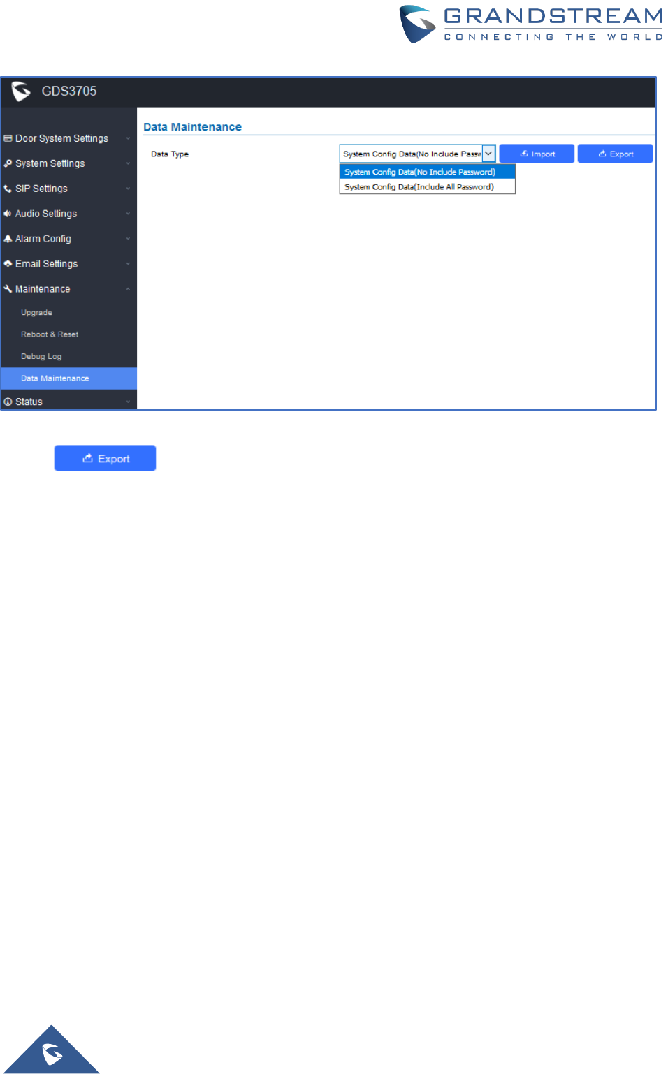
P a g e | 63
GDS3705 User Manual
Version 1.0.0.20
Figure 55: Data Maintenance Page
Click on to save the GDS3705 configuration in a predefined directory.
Note: Users can either select to include all the passwords (SIP, FTP, Remotes access…) on the
configuration files exported or not including the passwords as displayed on the previous figure.
Status
This page displays GDS3705 system and network information.
System Info
This page displays information such as the product model, the hardware version, firmware…
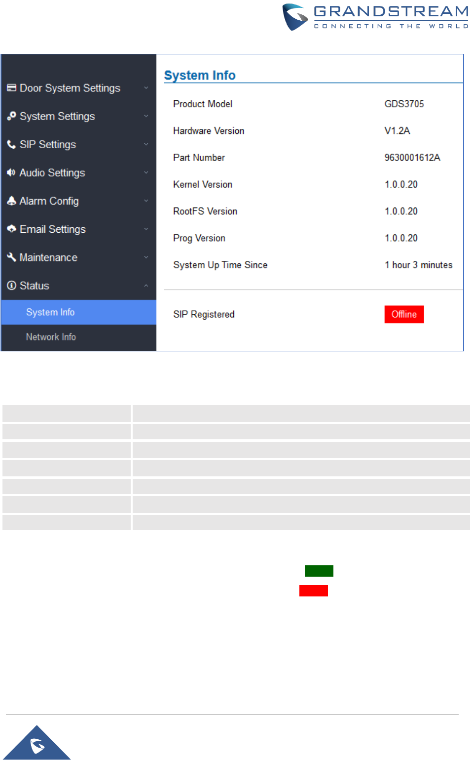
P a g e | 64
GDS3705 User Manual
Version 1.0.0.20
Figure 56: System Info Page
Table 26: System Info
Product Model
Displays the Product Model.
Hardware Version
Displays the Hardware Version.
Part Number
Displays the Part Number.
Kernel Version
Displays the Kernel Version.
RootFS Version
Displays the RootFS Version.
Prog Version
Displays the Prog Version.
System Up Time Since
Displays the time since the first boot of the GDS3705.
Notes:
• When the SIP account is registered, the status display will be Online
• When SIP account is unregistered, the status display will be Offline
Network Info
This page displays the network system information of GDS3705.
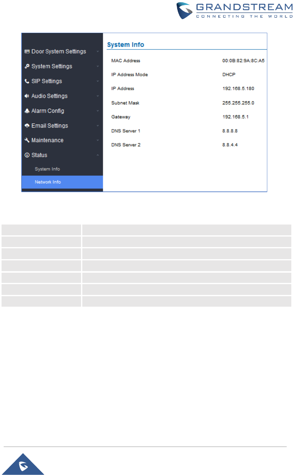
P a g e | 65
GDS3705 User Manual
Version 1.0.0.20
Figure 57: Network Info Page
Table 27: Network Info
MAC Address
Displays the GDS3705 MAC Address.
IP Address Mode
Displays the IP address mode used.
IP Address
Displays the IP address of the GDS3705.
Subnet Mask
Displays the Subnet Mask used.
Gateway
Displays the GDS3705 Gateway.
DNS Server 1
Displays the Preferred DNS Server.
DNS Server 2
Displays the secondary DNS Server.
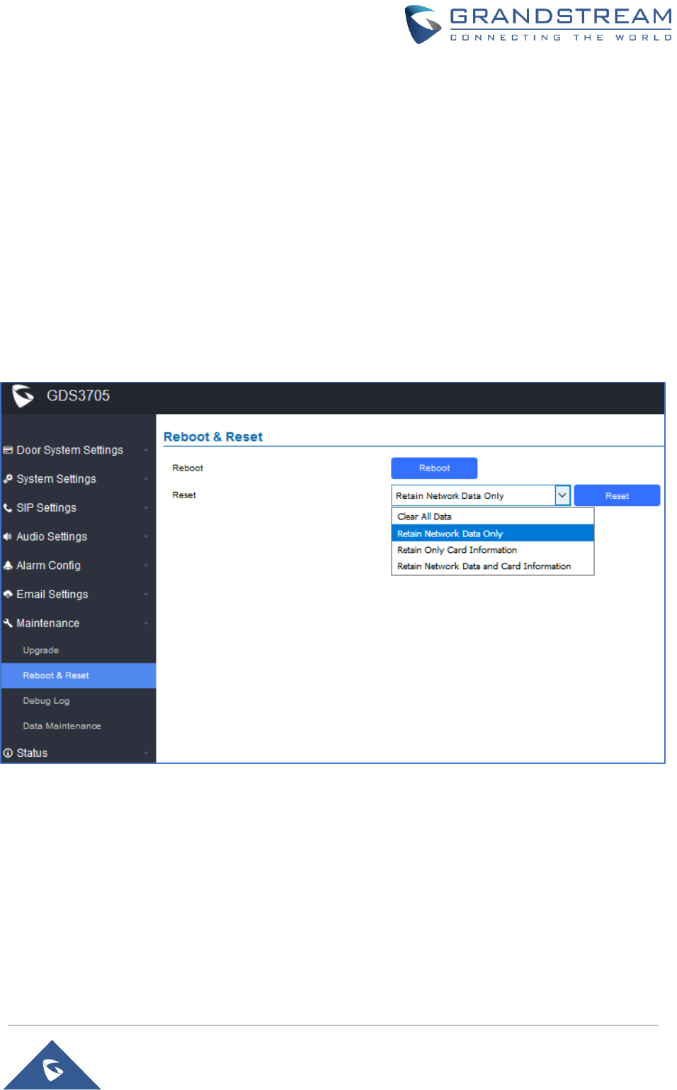
P a g e | 66
GDS3705 User Manual
Version 1.0.0.20
FACTORY RESET
Restore to Factory Default Via Web GUI
To perform factory reset to the GDS3705 via the Web GUI, please refer to following steps:
1. Access to GDS3705 Web GUI using the using the shipped default password.
2. Navigate to Maintenance Reboot & Reset.
3. Select the reset type from Rest drop down menu and press reset button as displayed on the
following screenshot.
Figure 58: Reset via Web GUI
Hard Factory Reset
Some users did not keep the revised password safely and forgot the changed password. Due to GDS3705
did NOT have built-in reset button (Grandstream purposely designed this way to enhance security), this will
make the GDS3705 inaccessible even for the true owner who lost the changed password.
Below is a photo of the normal connection of the provided Wiegand cable.
Important note: Power must NOT be lost while performing hard factory reset.
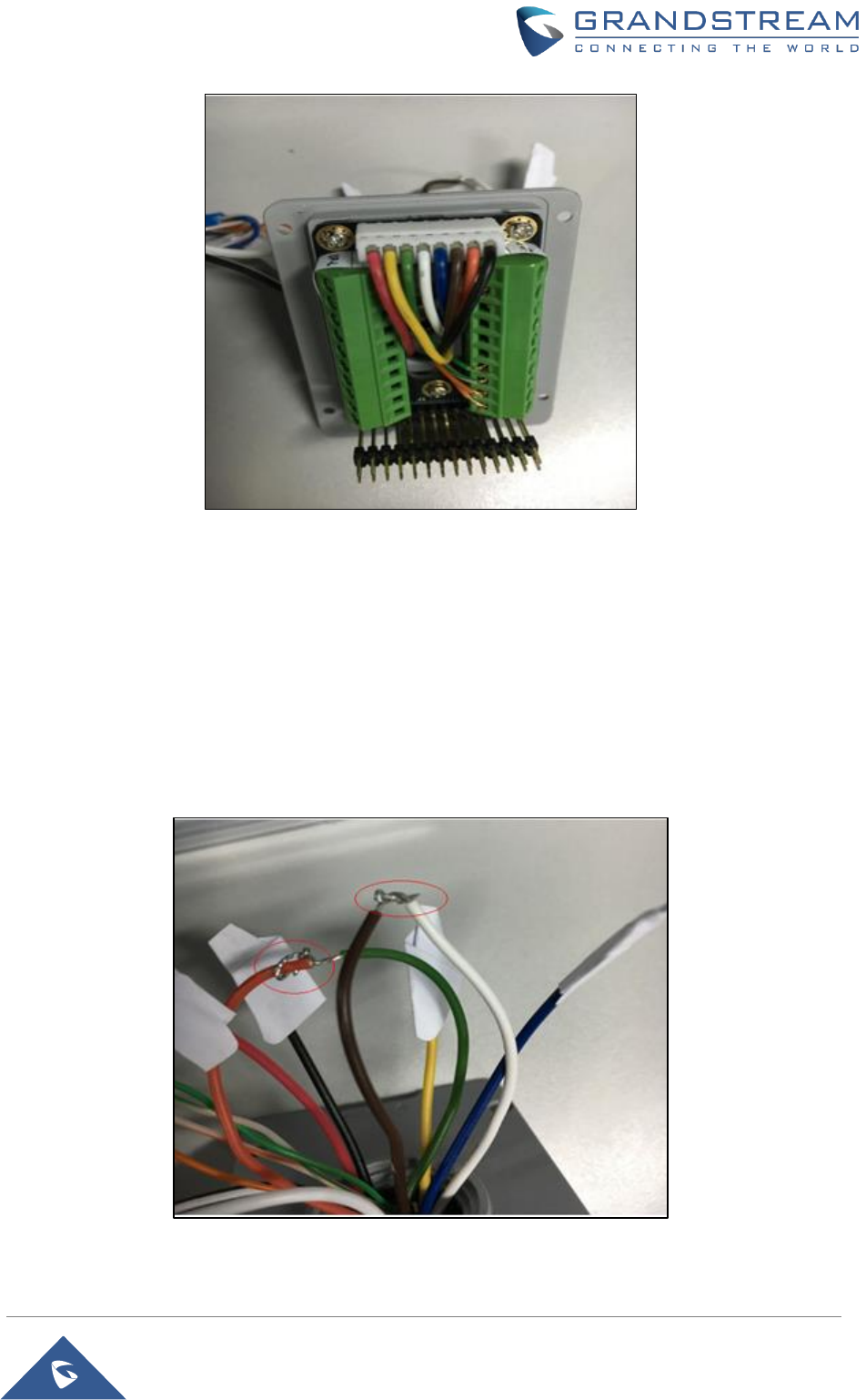
P a g e | 67
GDS3705 User Manual
Version 1.0.0.20
Figure 59: Wiegand Interface Cable
To perform hard factory reset to the GDS3705, please refer to following steps:
1. Power OFF the GDS3705.
2. Take the provided Wiegand cable, connect (or shorting) the related color wires as illustrated on the
following picture. Please make sure the connection is correct and solid:
▪ Connect WHITE and BROWN cable together.
▪ Connect GREEN and ORANGE cable together.
Figure 60: Wiegand Cable Connection

P a g e | 68
GDS3705 User Manual
Version 1.0.0.20
3. Power ON the GDS3705. In about 10 seconds, the key pad LED lighting will change from solid
lighting to blinking, the blinking time window is about 30 seconds. The user needs to enter the
following key combination *0# while the LED is blinking.
Notes:
•If the correct key combination inputted, the last key input will play with a long tone, illustrating
the correct key combination entered, then the GDS3705 will get into factory reset mode.
•During the blinking time window, if the user does not finish the key combination operation, or
pressed the wrong key combination, the GDS3705 will play short beep quickly three times
illustrating error. Nothing will happen and the GDS3705 will get into normal booting process.
User who wants to do hard factory reset has to perform the operation from the beginning
again.
4. After 3 ~ 5 minutes the GDS3705 will finish performing the reset process, then the user can log into
the GDS3705 web GUI using the shipped default password.
5. User has to power OFF the GDS3705, unplug the Wiegand cable, power ON the GDS3705 again
and make sure the GDS3705 is running correctly.

P a g e | 69
GDS3705 User Manual
Version 1.0.0.20
EXPERIENCING THE GDS3705
Please visit our website: http://www.grandstream.com to receive the most up-to-date updates on firmware
releases, additional features, FAQs, documentation and news on new products.
We encourage you to browse our product related documentation, FAQs and User and Developer Forum for
answers to your general questions. If you have purchased our products through a Grandstream Certified
Partner or Reseller, please contact them directly for immediate support.
Our technical support staff is trained and ready to answer all your questions. Contact a technical support
member or submit a trouble ticket online to receive in-depth support.
Thank you again for purchasing Grandstream Door Phone System, it will be sure to bring convenience and
color to both your business and personal life.
FCC Compliance Statement:
This device complies with part 15 of the FCC Rules. Operation is subject to the following two conditions:
(1)This device may not cause harmful interference, and (2) this device must accept any interference
received, including interference that may cause undesired operation.
Important: Any Changes or modifications not expressly approved by the party responsible for compliance
could void the user's authority to operate the equipment.
Note: This equipment has been tested and found to comply with the limits for a Class B digital device,
pursuant to part 15 of the FCC Rules.
These limits are designed to provide reasonable protection against harmful interference in a residential
installation. This equipment generates, uses and can radiate radio frequency energy and, if not installed
and used in accordance with the instructions, may cause harmful interference to radio communications.
However, there is no guarantee that interference will not occur in a particular installation.
If this equipment does cause harmful interference to radio or television reception, which can be
determined by turning the equipment off and on, the user is encouraged to try to correct the
interference by one or more of the following measures:
-Reorient or relocate the receiving antenna.
-Increase the separation between the equipment and receiver.
-Connect the equipment into an outlet on a circuit different from that to which the receiver is connected.
-Consult the dealer or an experienced radio/TV technician for help.