Grandstream Networks HA100 HIGH AVAILABILITY UCM CONNECTOR User Manual
Grandstream Networks, Inc. HIGH AVAILABILITY UCM CONNECTOR
UserManual.wiki
>
Grandstream Networks
>
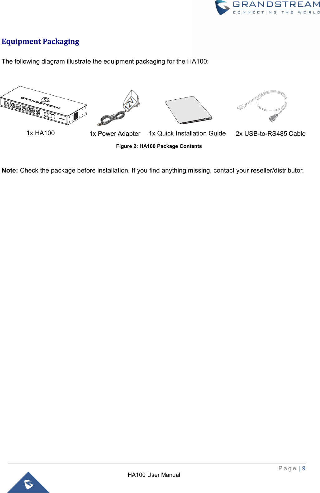
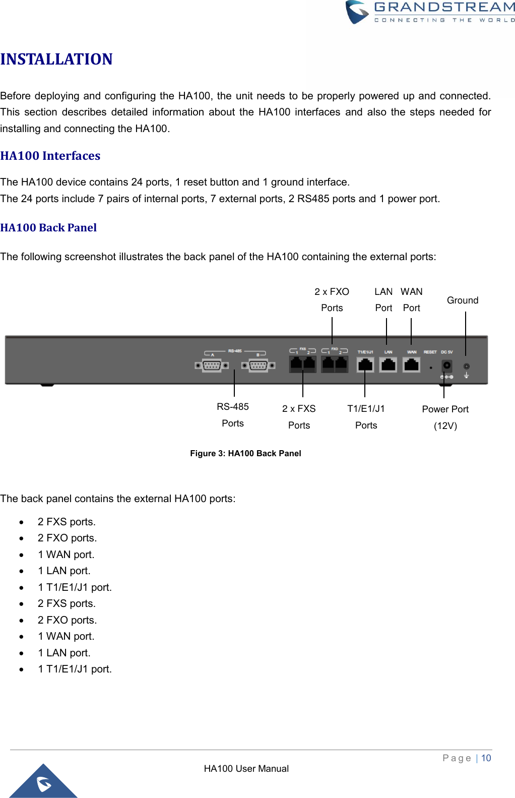
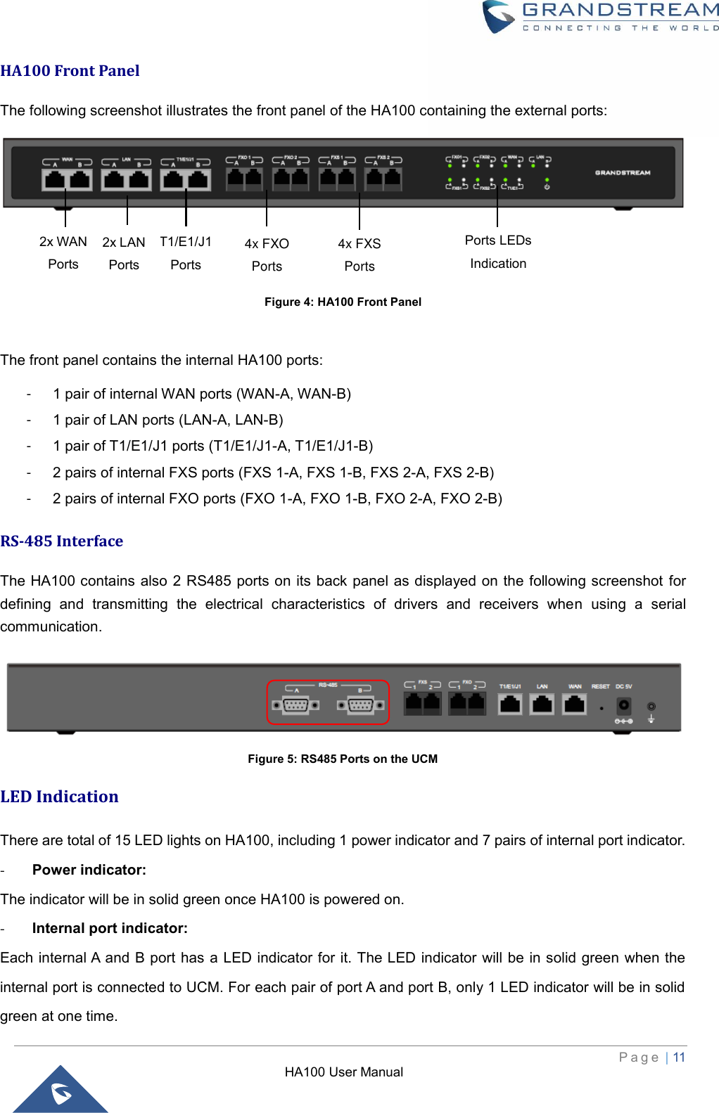
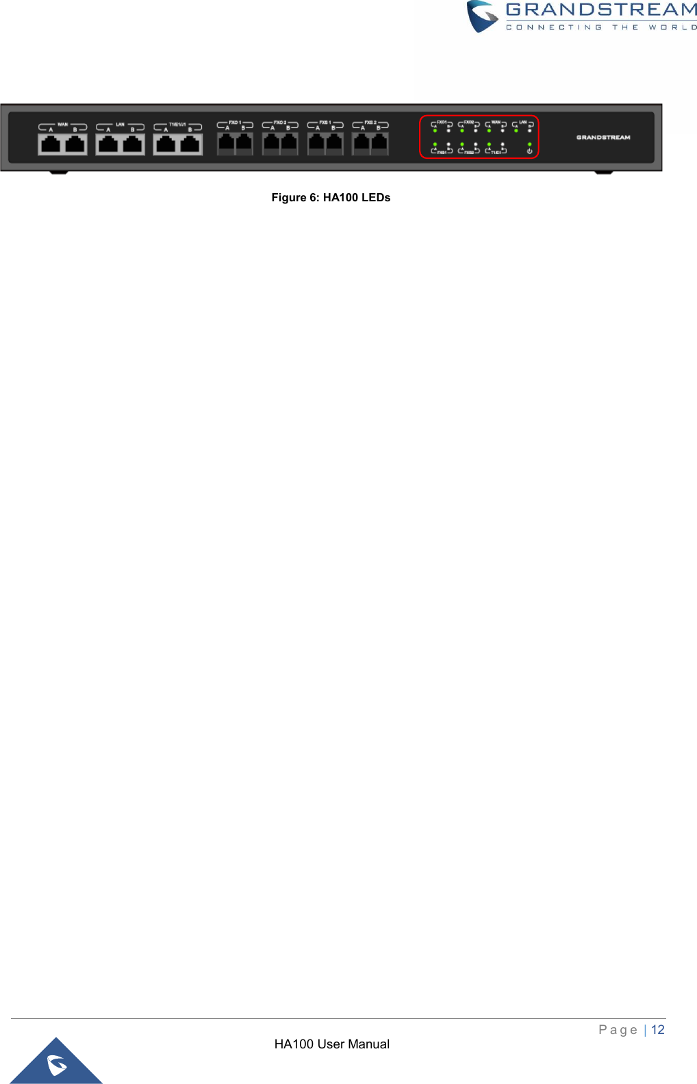
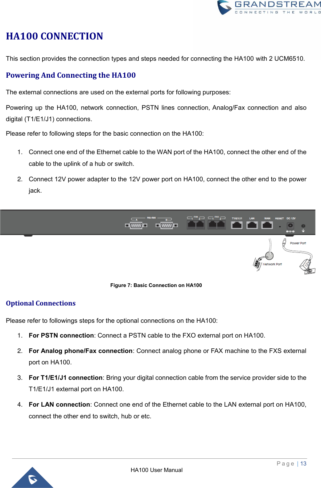
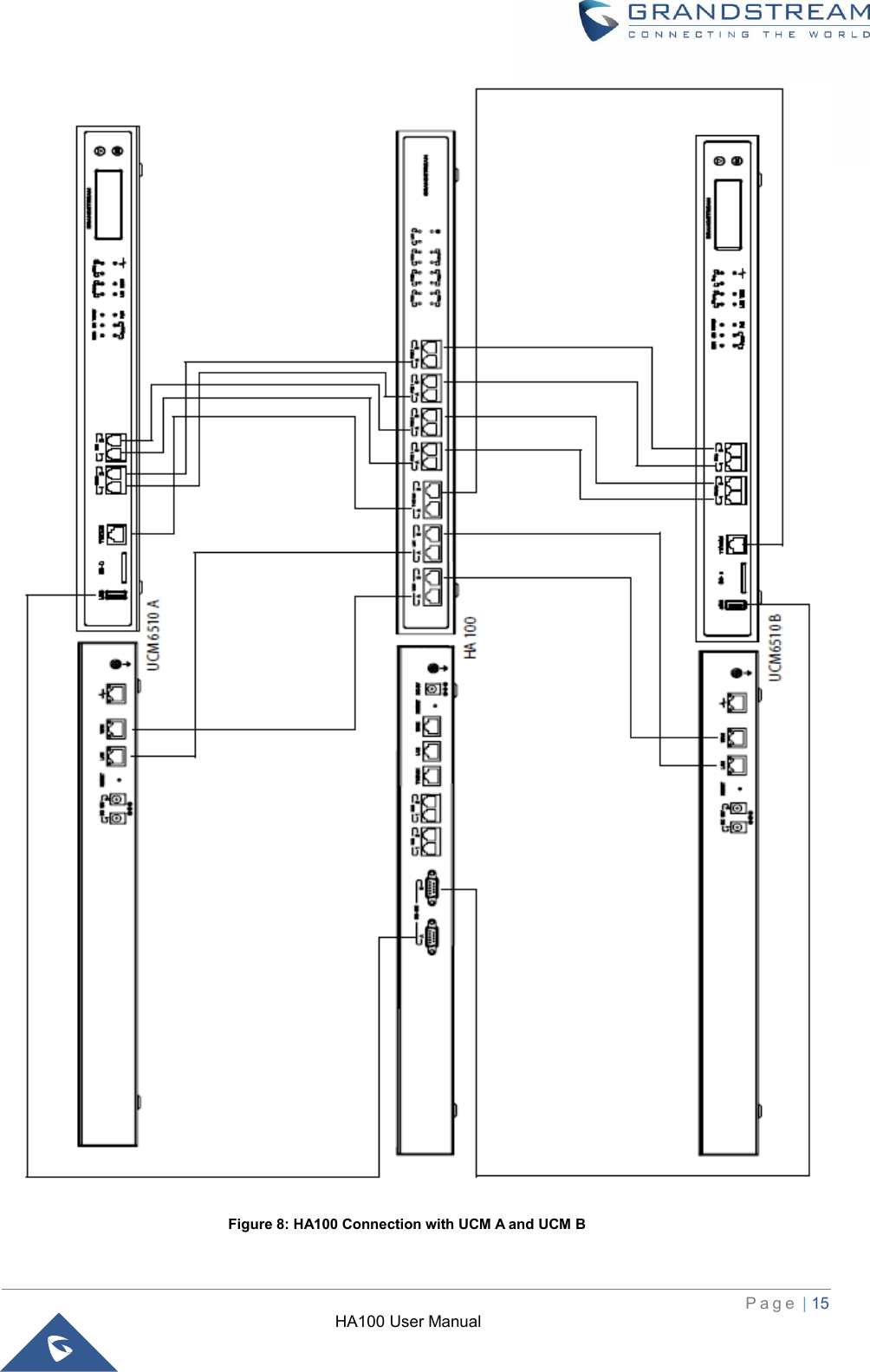
HA100 User Manual
User manual
Navigation menu
Upload a User Manual
Namespaces
Wiki Guide
HTML
PDF
Info
Views
User Manual
Discussion / Help
Navigation