Grandstream Networks HA100 HIGH AVAILABILITY UCM CONNECTOR User Manual
Grandstream Networks, Inc. HIGH AVAILABILITY UCM CONNECTOR
User manual

Grandstream Networks, Inc.
HA100
User Manual

HA100 User Manual
P a g e | 2
Table of Contents
CHANGE LOG ................................................................................................................ 4
Firmware Version 1.0.0.1 ....................................................................................................................... 4
INTRODUCTION ............................................................................................................. 7
PRODUCT OVERVIEW .................................................................................................. 8
Feature Highlights .................................................................................................................................. 8
HA100 Technical Specifications ............................................................................................................. 8
INSTALLATION ............................................................................................................ 10
HA100 Interfaces ................................................................................................................................. 10
HA100 Back Panel........................................................................................................................ 10
HA100 Front Panel ....................................................................................................................... 11
RS-485 Interface ........................................................................................................................... 11
LED Indication ...................................................................................................................................... 11
HA100 CONNECTION .................................................................................................. 13
Powering And Connecting the HA100 ................................................................................................. 13
Optional Connections ................................................................................................................... 13
Connecting The HA100 with 2 UCM6510 ............................................................................................ 14
Environment .................................................................................................................................. 14
Connection Steps ......................................................................................................................... 14
Function Description ..................................................................................................................... 16
EXPERIENCING HA100 ............................................................................................... 17

HA100 User Manual
P a g e | 3
Table of Tables
Table 1: HA100 Features at a Glance ........................................................................................................... 8
Table 2: HA100 Technical Specifications ...................................................................................................... 8
Table of Figures
Figure 1: High Availability .............................................................................................................................. 7
Figure 2: HA100 Package Contents ............................................................................................................. 9
Figure 3: HA100 Back Panel ....................................................................................................................... 10
Figure 4: HA100 Front Panel ...................................................................................................................... 11
Figure 5: RS485 Ports on the UCM ............................................................................................................ 11
Figure 6: HA100 LEDs ................................................................................................................................ 12
Figure 7: Basic Connection on HA100 ........................................................................................................ 13
Figure 8: HA100 Connection with UCM A and UCM B ............................................................................... 15

HA100 User Manual
P a g e | 4
CHANGE LOG
This section documents significant changes from previous firmware versions. Only major new features or
major document updates are listed here. Minor updates for corrections or editing are not documented here.
Firmware Version 1.0.0.1
• This is the initial version for HA100.

HA100 User Manual
P a g e | 5
COPYRIGHT
©2017 Grandstream Networks, Inc. http://www.grandstream.com
All rights reserved. Information in this document is subject to change without notice. Reproduction or
transmittal of the entire or any part, in any form or by any means, electronic or print, for any purpose without
the express written permission of Grandstream Networks, Inc. is not permitted. The latest electronic version
of this user manual is available for download here: http://www.grandstream.com/support
Grandstream is a registered trademark and Grandstream logo is trademark of Grandstream Networks, Inc.
in the United States, Europe and other countries.
CAUTION
Changes or modifications to this product not expressly approved by Grandstream, or operation of this
product in any way other than as detailed by this User Manual, could void your manufacturer warranty.
WARNING
Please do not use a different power adaptor with your devices as it may cause damage to the products and
void the manufacturer warranty.

HA100 User Manual
P a g e | 6
GNU GPL INFORMATION
HA100 firmware contains third-party software licensed under the GNU General Public License (GPL).
Grandstream uses software under the specific terms of the GPL. Please see the GNU General Public
License (GPL) for the exact terms and conditions of the license.
Grandstream GNU GPL related source code can be downloaded from Grandstream web site from:
http://www.grandstream.com/support/faq/gnu-general-public-license/gnu-gpl-information-download

HA100 User Manual
P a g e | 7
INTRODUCTION
Thank you for using Grandstream HA100. To meet the requirements of our customers, Grandstream
releases the HA100 which is a module designed to achieve High Availability function for our enterprise grad
IP-PBX UCM6510. It contains a set of external ports and splits each of them into two internal ports: Port A
and Port B. The ports on the 2 UCM6510s should be connected to each Port A and Port B respectively and
the external ports on the HA100 provide PBX service. Powered by an advanced hardware platform and
revolutionary software functionalities, the connection between the UCM6510 and HA100 offers a
breakthrough turnkey solution for converged voice, video, data, fax, security surveillance, and mobility
applications out of the box without any extra license fees or recurring costs.
Figure 1: High Availability
Primary UCM6510
HA100
Backup UCM6510
HA100 User Manual
P a g e | 8
PRODUCT OVERVIEW
Feature Highlights
The following tables contain the major features of the HA100:
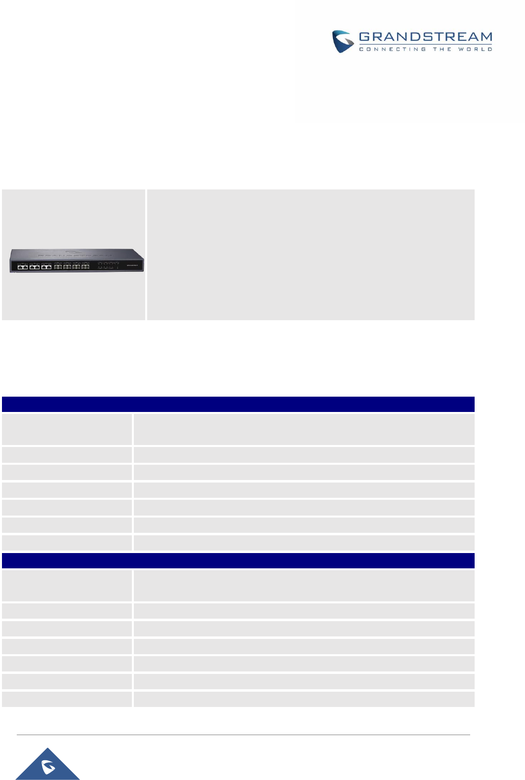
Table 1: HA100 Features at a Glance
HA100 Technical Specifications
The following table resumes all the physical and technical specifications for HA100:
Table 2: HA100 Technical Specifications
Back Panel Interface
Analog Telephone FXS
Ports
2 ports
PSTN Line FXO Ports
2 ports
T1/E1 Interface
1 port
Network Interfaces
1 LAN/ 1 WAN
RS-485
2; 1 for Primary UCM6510; 1 for Secondary UCM6510
Reset Switch
Yes
Universal Power Supply
DC Power Port
Front Panel Interface
Analog Telephone FXS
Ports
2; 1 FXS A, 1 FXS B
PSTN Line FXO Ports
2; 1 FXO A, 1 FXO B
T1/E1 Interface
2 ports; T1/E1 A, T1/E1 B
LED Indicators
Power, T1/E1, FXS, FXO, LAN, WAN
CPU
ARM Coretex-MO +
Memory & Flash
4KB SRAM Memory, 16KB Flash
Microchip
Atmel SAM D11D 24-pin QFN
• Designed to provide a failover solution for the UCM6510.
• Connect two UCM6510s to the HA100 to create a back-up solution
and automatically switch to a secondary UCM6510 if the main one
fails.
• An ideal complimentary connector to the UCM6510 for businesses
that need a reliable UC system without any interruptions or failures.
• Up to 14 LED indicators that can be controlled by GPIO ports.
HA100

HA100 User Manual
P a g e | 9
Equipment Packaging
The following diagram illustrate the equipment packaging for the HA100:
Note: Check the package before installation. If you find anything missing, contact your reseller/distributor.
1x Quick Installation Guide
1x Power Adapter
1x HA100
2x USB-to-RS485 Cable
Figure 2: HA100 Package Contents
HA100 User Manual
P a g e | 10
INSTALLATION
Before deploying and configuring the HA100, the unit needs to be properly powered up and connected.
This section describes detailed information about the HA100 interfaces and also the steps needed for
installing and connecting the HA100.
HA100 Interfaces
The HA100 device contains 24 ports, 1 reset button and 1 ground interface.
The 24 ports include 7 pairs of internal ports, 7 external ports, 2 RS485 ports and 1 power port.
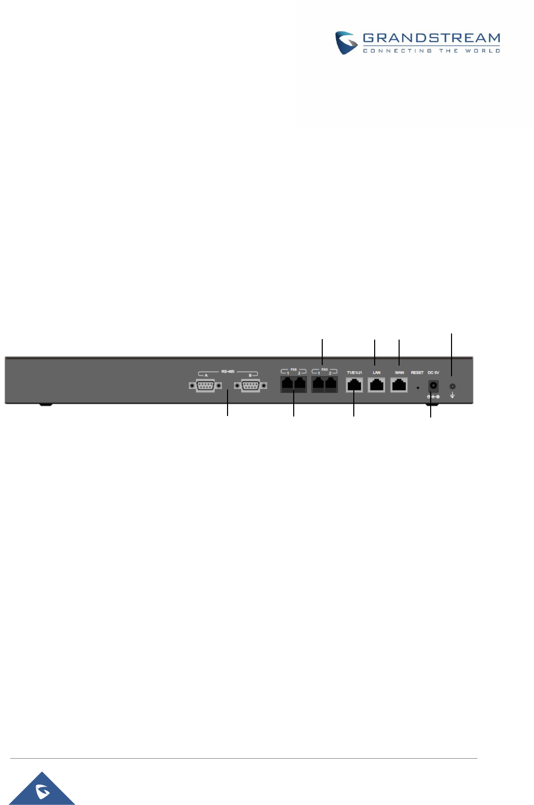
HA100 Back Panel
The following screenshot illustrates the back panel of the HA100 containing the external ports:
Figure 3: HA100 Back Panel
The back panel contains the external HA100 ports:
• 2 FXS ports.
• 2 FXO ports.
• 1 WAN port.
• 1 LAN port.
• 1 T1/E1/J1 port.
• 2 FXS ports.
• 2 FXO ports.
• 1 WAN port.
• 1 LAN port.
• 1 T1/E1/J1 port.
Power Port
(12V)
T1/E1/J1
Ports
2 x FXS
Ports
RS-485
Ports
2 x FXO
Ports
LAN
Port
WAN
Port
Ground
HA100 User Manual
P a g e | 11
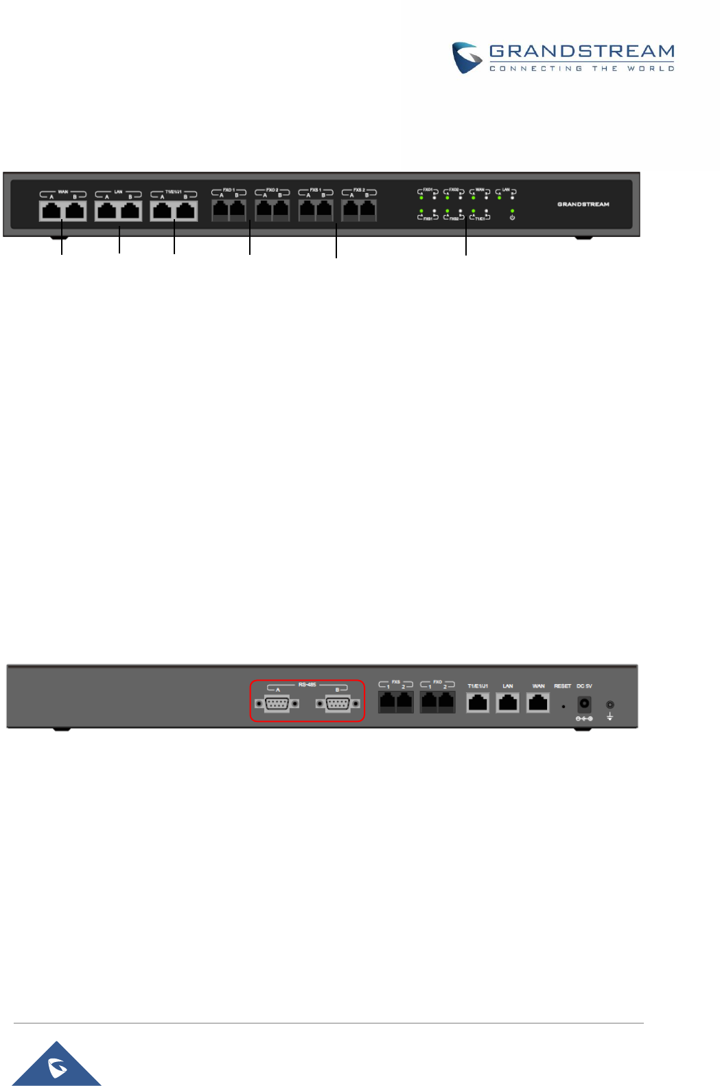
HA100 Front Panel
The following screenshot illustrates the front panel of the HA100 containing the external ports:
Figure 4: HA100 Front Panel
The front panel contains the internal HA100 ports:
- 1 pair of internal WAN ports (WAN-A, WAN-B)
- 1 pair of LAN ports (LAN-A, LAN-B)
- 1 pair of T1/E1/J1 ports (T1/E1/J1-A, T1/E1/J1-B)
- 2 pairs of internal FXS ports (FXS 1-A, FXS 1-B, FXS 2-A, FXS 2-B)
- 2 pairs of internal FXO ports (FXO 1-A, FXO 1-B, FXO 2-A, FXO 2-B)
RS-485 Interface
The HA100 contains also 2 RS485 ports on its back panel as displayed on the following screenshot for
defining and transmitting the electrical characteristics of drivers and receivers when using a serial
communication.
Figure 5: RS485 Ports on the UCM
LED Indication
There are total of 15 LED lights on HA100, including 1 power indicator and 7 pairs of internal port indicator.
- Power indicator:
The indicator will be in solid green once HA100 is powered on.
- Internal port indicator:
Each internal A and B port has a LED indicator for it. The LED indicator will be in solid green when the
internal port is connected to UCM. For each pair of port A and port B, only 1 LED indicator will be in solid
green at one time.
Ports LEDs
Indication
T1/E1/J1
Ports
4x FXS
Ports
2x WAN
Ports
4x FXO
Ports
2x LAN
Ports

HA100 User Manual
P a g e | 12
Figure 6: HA100 LEDs
HA100 User Manual
P a g e | 13
HA100 CONNECTION
This section provides the connection types and steps needed for connecting the HA100 with 2 UCM6510.
Powering And Connecting the HA100
The external connections are used on the external ports for following purposes:
Powering up the HA100, network connection, PSTN lines connection, Analog/Fax connection and also
digital (T1/E1/J1) connections.
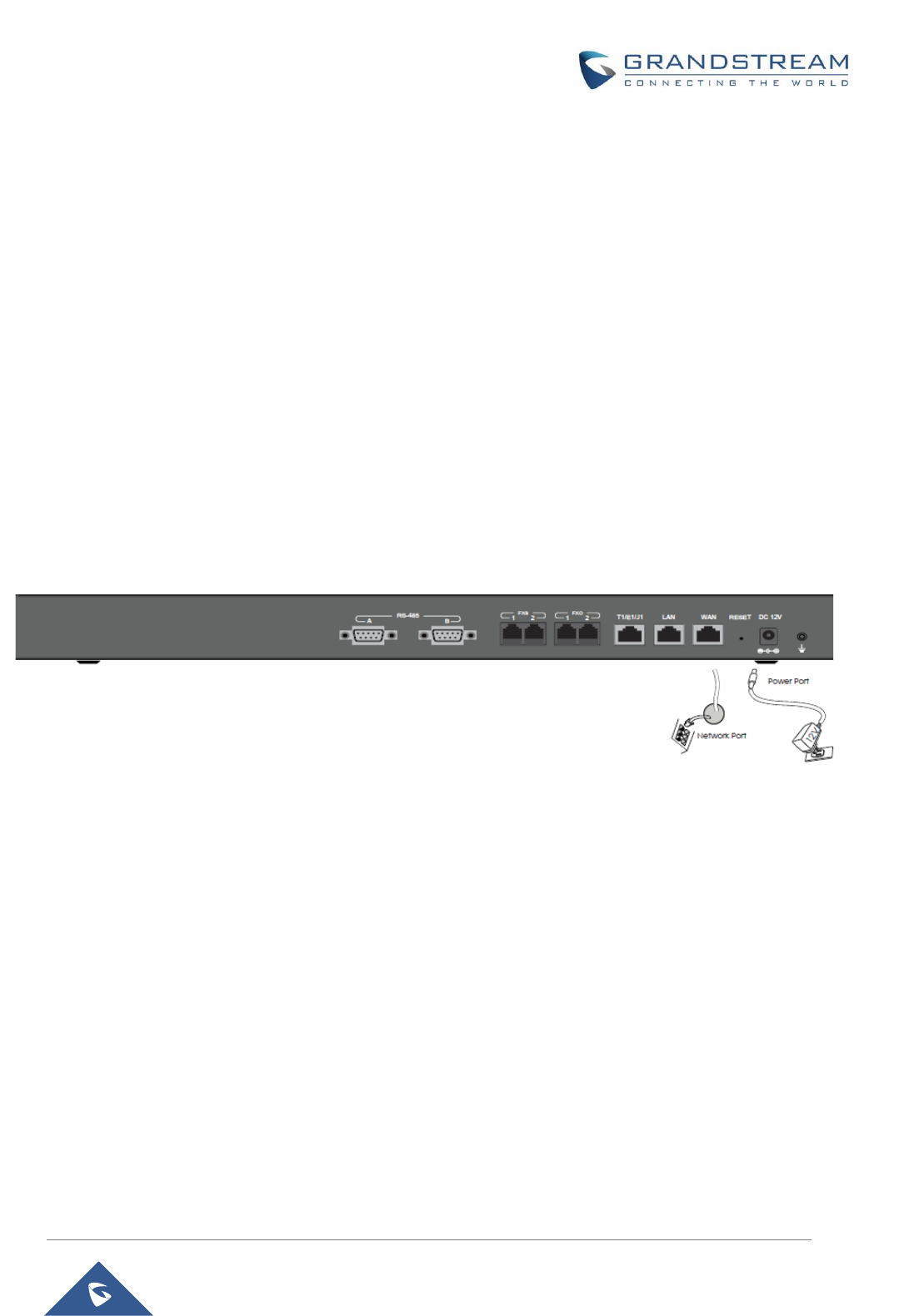
Please refer to following steps for the basic connection on the HA100:
1. Connect one end of the Ethernet cable to the WAN port of the HA100, connect the other end of the
cable to the uplink of a hub or switch.
2. Connect 12V power adapter to the 12V power port on HA100, connect the other end to the power
jack.
Figure 7: Basic Connection on HA100
Optional Connections
Please refer to followings steps for the optional connections on the HA100:
1. For PSTN connection: Connect a PSTN cable to the FXO external port on HA100.
2. For Analog phone/Fax connection: Connect analog phone or FAX machine to the FXS external
port on HA100.
3. For T1/E1/J1 connection: Bring your digital connection cable from the service provider side to the
T1/E1/J1 external port on HA100.
4. For LAN connection: Connect one end of the Ethernet cable to the LAN external port on HA100,
connect the other end to switch, hub or etc.

HA100 User Manual
P a g e | 14
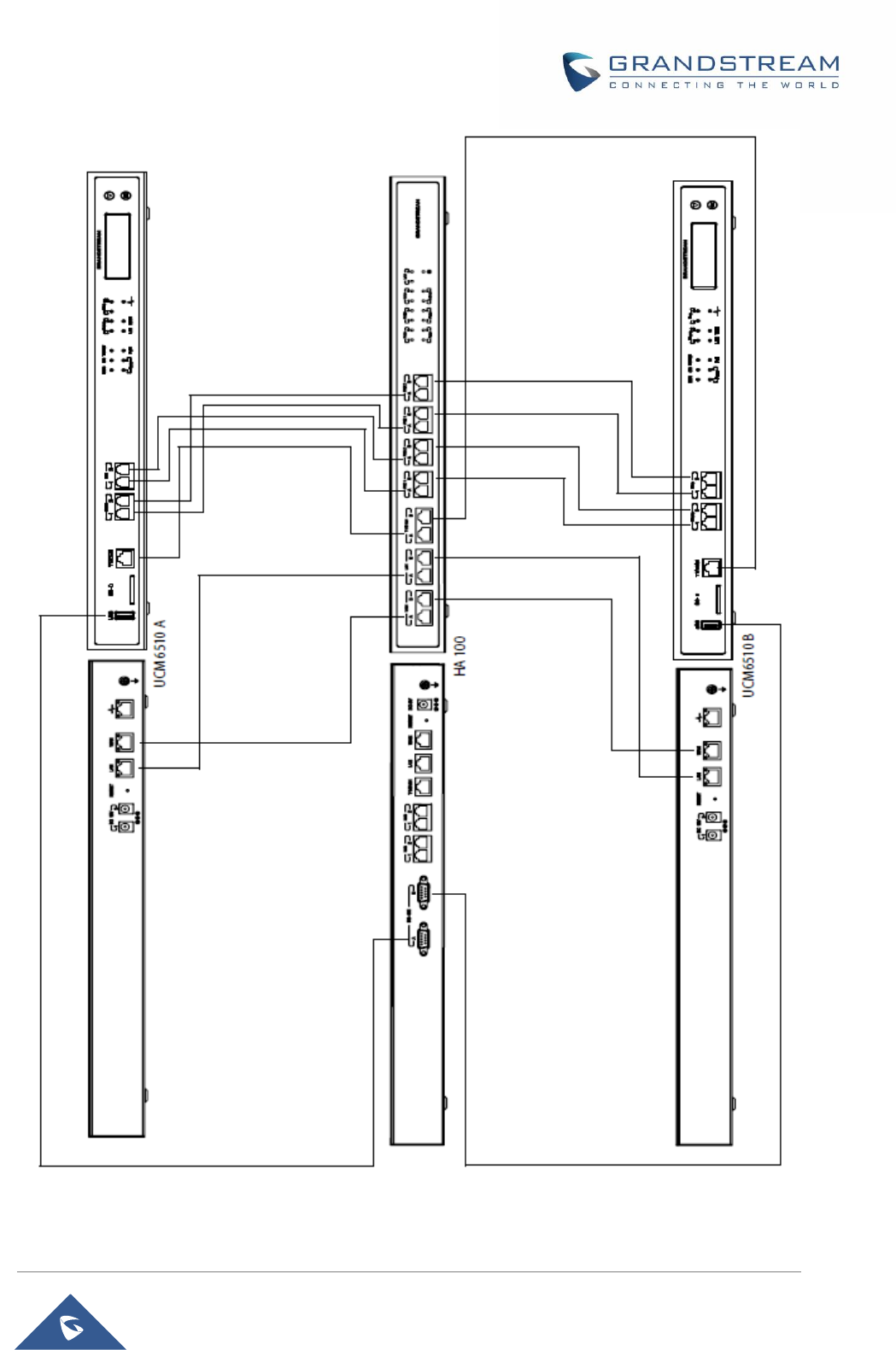
Connecting The HA100 with 2 UCM6510
This is the connection between HA100 and the 2 UCM6510s, one acting as primary server (providing online
service) and the other as backup server (it doesn’t provide service until the primary server is down).
Environment
For the internal connection, we will assume that users have already the following environment items ready:
- 4 Ethernet cables and 2 T1/E1/J1 cables.
- 8 PSTN cables.
- 2 USB-to-RS485 serial cables.
- 2 UCM6510 (UCM A and UCM B).
Connection Steps
Please refer to followings steps for the basic internal connections between HA100, UCM A and UCM B:
1. Connect respectively the FXO port, FXS port, E1/T1/J1 port, WAN port and LAN port on UCM A to
the FXO-A port, FXS-A port, E1/T1/J1-A port, WAN-A port and LAN-A port on HA100.
2. Use the USB-to-RS485 serial cable to connect UCM A’s USB port to the RS485-A port on HA100.
3. Connect respectively the FXO port, FXS port, E1/T1/J1 port, WAN port and LAN port on UCM B to
the FXO-B port, FXS-B port, E1/T1/J1-B port, WAN-B port and LAN-B port on HA100.
4. Use the USB-to-RS485 serial cable to connect UCM B’s USB port to the RS485-B port on HA100.
5. Use Ethernet cable to connect the Heartbeat ports on Primary UCM A and Backup UCM B.
The following diagram illustrate the connection between the HA100 and 2 UCM6510 PBXs.
In this scenario, the HA100 separates the external port into the corresponding internal ports (A and B), by
default, the port A is always connected and port B is always disconnected, so only one UCM device is
successfully connected at one time. If the primary UCM (UCM6510 A) detects problem on itself, it will send
signaling to HA100 via USB-to-RS485 cable to switch the connection towards the backup server, or in case
the primary server is down by any reasons, for instance power outage, the HA100 will then switch the
connection from port A to port B, making port B successfully connected and having backup UCM (UCM6510
B) to provide service.
HA100 User Manual
P a g e | 15
Figure 8: HA100 Connection with UCM A and UCM B

HA100 User Manual
P a g e | 16
Function Description
HA100 separates the external port into the corresponding internal ports (A and B). By default, port A is
always connected and port B is always disconnected, so only one UCM device is successfully connected
at one time. When the 2 UCMs connect to HA100 via port A and port B, the primary UCM uses the external
port on HA100 for data transmission. Additionally, the RS485 port on HA100 receives signaling from UCM
to achieve the switch between port A and port B.
If the internal port A on HA100 is connected successfully with the corresponding port on primary UCM, the
LED indicator for port A on HA100 will be in solid green. The primary UCM uses the external ports on HA100
to provide service. In this case, the LED indicator for port B on HA100 will not light up and the backup UCM
doesn’t provide service.
If the primary UCM detects problem on itself, it will send signaling to HA100 via USB-to-RS485 cable.
HA100 will then switch the connection towards the backup server or in case the primary server is down by
any reasons, for instance power outage, the HA100 will then switch the connection from port A to port B,
making port B successfully connected and having backup UCM to provide service. In this case, the LED
indicator for port B on HA100 will light up in solid green while the LED indicator for port A will be off.

HA100 User Manual
P a g e | 17
EXPERIENCING HA100
Please visit our Website: http://www.grandstream.com to receive the most up- to-date updates on firmware
releases, additional features, FAQs, documentation and news on new products.
We encourage you to browse our product related documentation, FAQs and User and Developer Forum
for answers to your general questions. If you have purchased our products through a Grandstream
Certified Partner or Reseller, please contact them directly for immediate support.
Our technical support staff is trained and ready to answer all of your questions. Contact a technical support
member or submit a trouble ticket online to receive in-depth support.
Thank you again for using Grandstream HA100 module, it will be sure to bring reliability to your business
Telephony infrastructure.
FCC Compliance Statement:
This device complies with part 15 of the FCC Rules. Operation is subject to the following two
conditions:(1)This device may not cause harmful interference, and (2) this device must accept any
interference received, including interference that may cause undesired operation.
Important: Any Changes or modifications not expressly approved by the party responsible for
compliance could void the user's authority to operate the equipment.
Note: This equipment has been tested and found to comply with the limits for a Class B digital
device, pursuant to part 15 of the FCC Rules.
These limits are designed to provide reasonable protection against harmful interference in a
residential installation. This equipment generates, uses and can radiate radio frequency energy
and, if not installed and used in accordance with the instructions, may cause harmful interference
to radio communications. However, there is no guarantee that interference will not occur in a
particular installation.
If this equipment does cause harmful interference to radio or television reception, which can be
determined by turning the equipment off and on, the user is encouraged to try to correct the
interference by one or more of the following measures:
-Reorient or relocate the receiving antenna.
-Increase the separation between the equipment and receiver.
-Connect the equipment into an outlet on a circuit different from that to which the receiver is
connected.
-Consult the dealer or an experienced radio/TV technician for help.
※※※ End of user’s manual ※※※