Grandstream Networks HT701 Analog Telephone Adapter User Manual
Grandstream Networks, Inc. Analog Telephone Adapter
UserManual.wiki
>
Grandstream Networks
>
HT701 User Manual
User Manual
Navigation menu
Upload a User Manual
Namespaces
Wiki Guide
HTML
PDF
Info
Views
User Manual
Discussion / Help
Navigation


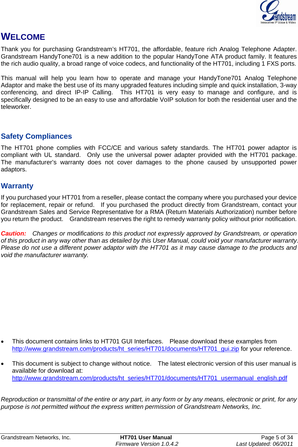
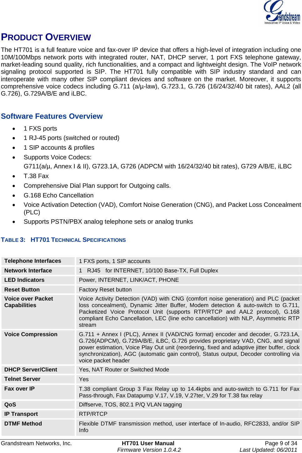
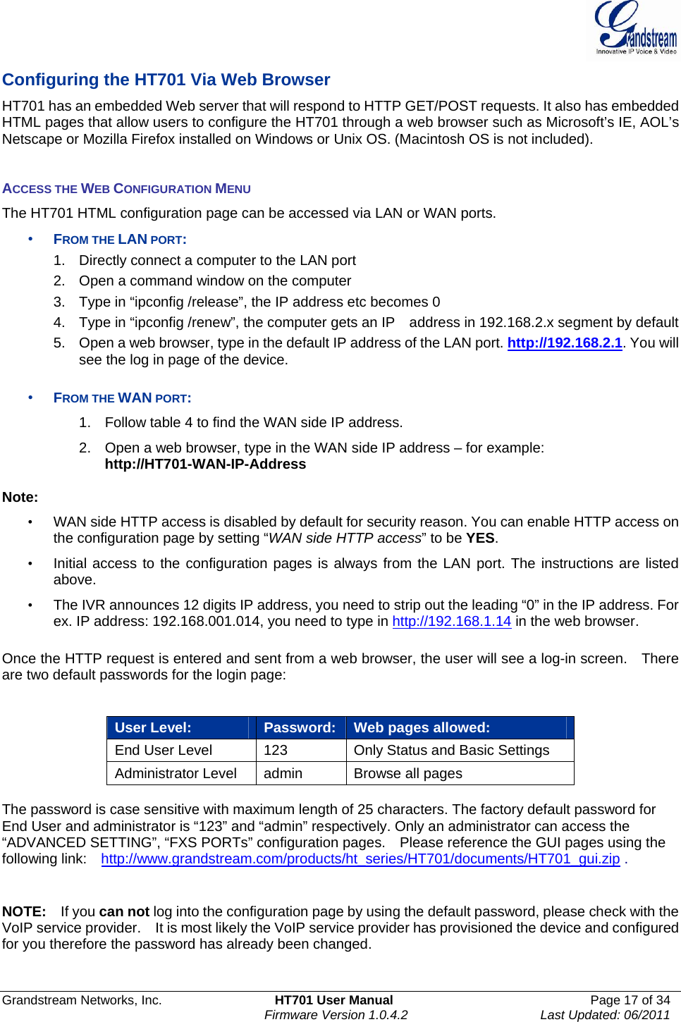
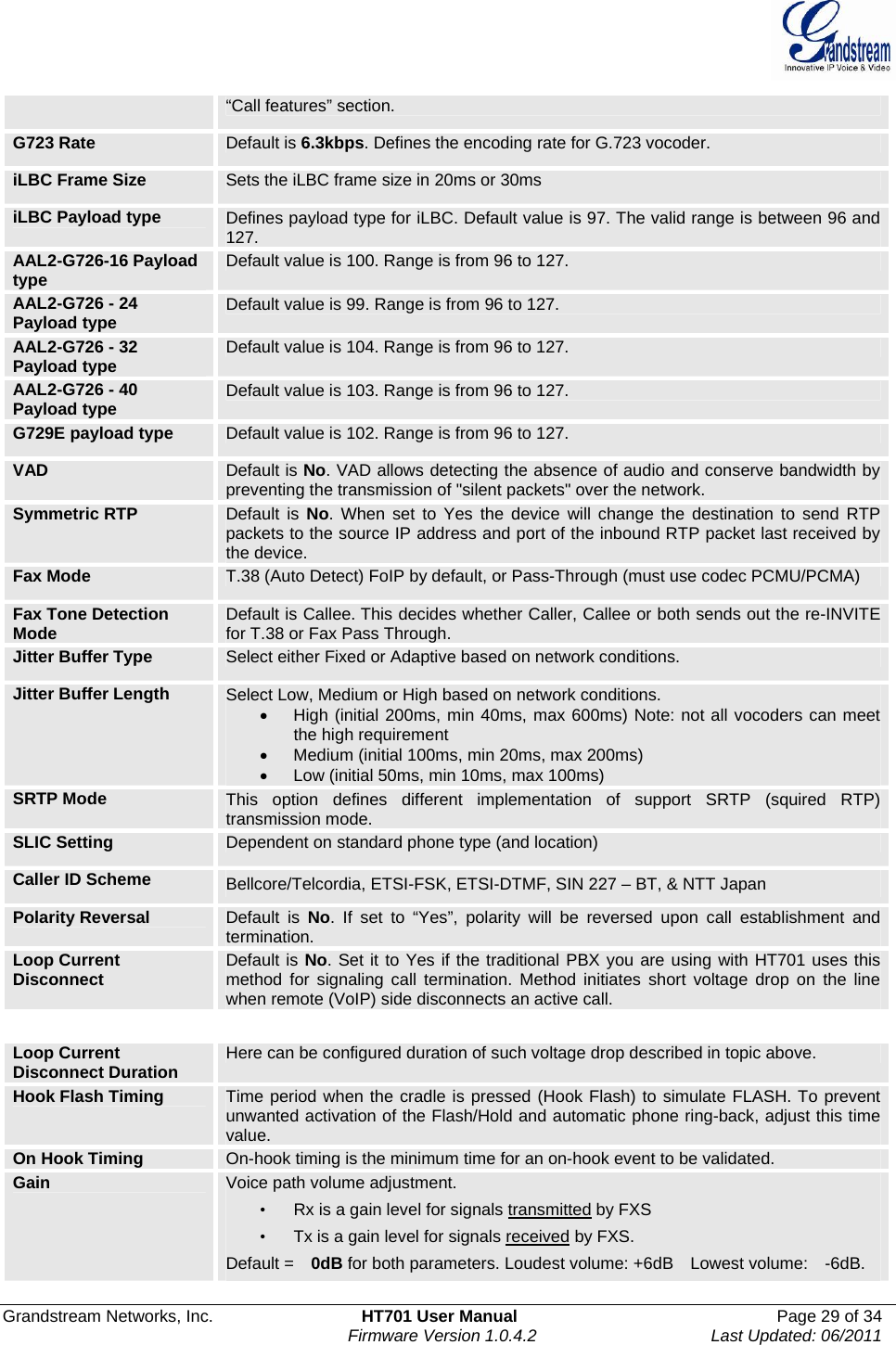
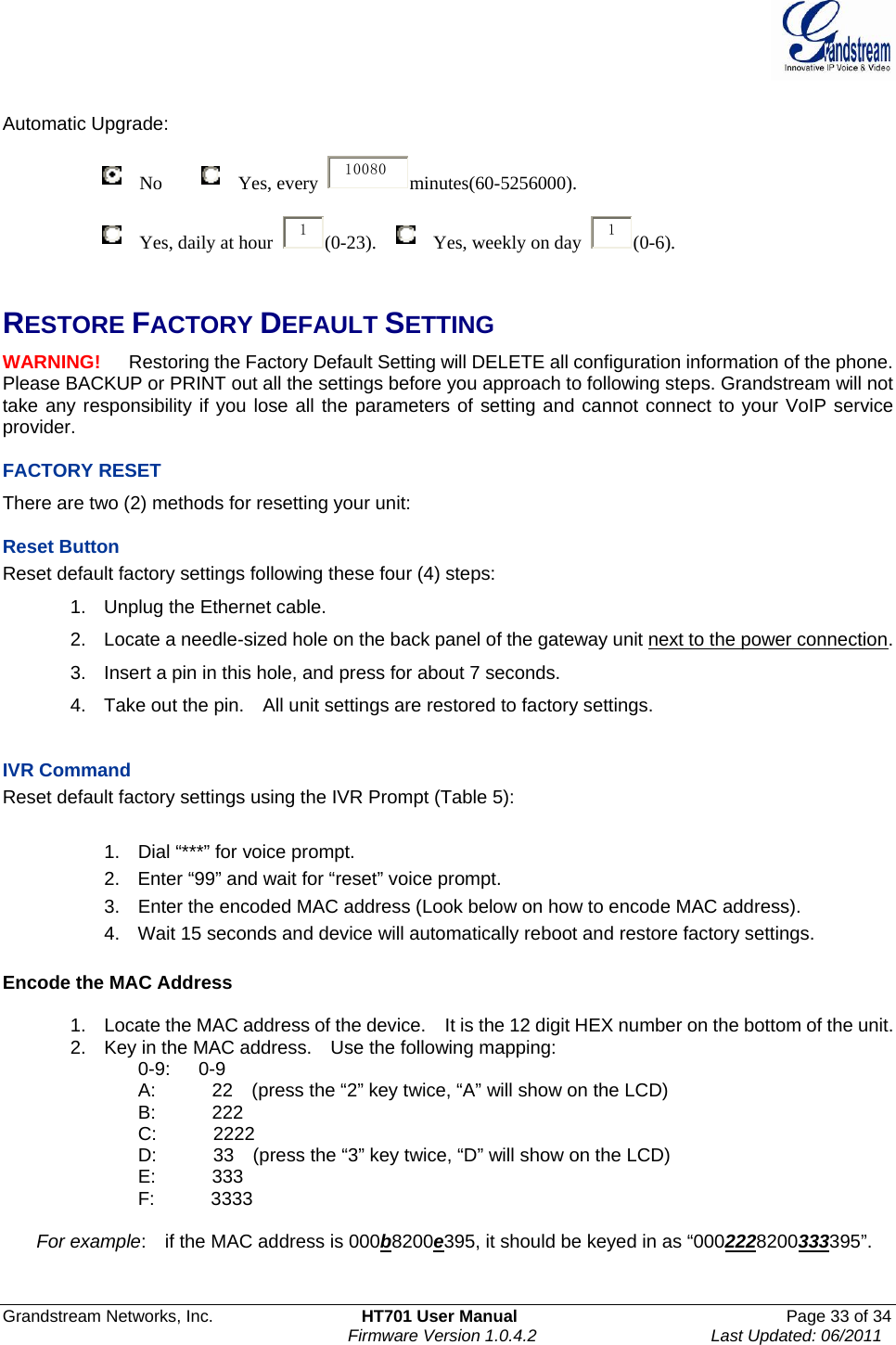
![Grandstream Networks, Inc. HT701 User Manual Page 19 of 34 Firmware Version 1.0.4.2 Last Updated: 06/2011 Web Port By default, HTTP uses port 80. This field is for customizable web port. Telnet Server Default is set to YES. IP Address There are two modes to operate the HT701: DHCP mode: all the field values for the Static IP mode are not used (even though they are still saved in the Flash memory.) The HT701 acquires its IP address from the first DHCP server it discovers from the LAN it is connected. Using the PPPoE feature: set thePPPoE account settings. The HT701 will establish a PPPoE session if any of the PPPoE fields is set. Static IP mode: configure the IP address, Subnet Mask, Default Router IP address, DNS Server 1 (primary), DNS Server 2 (secondary) fields. These fields are set to zero by default. DHCP hostname Default is blank. This option specifies the name of the client. This field is optional but may be required by some Internet Service Providers. DHCP domain Default is blank. This option specifies the domain name that client should use when resolving hostnames via the Domain Name System. DHCP vendor class ID Used by clients and servers to exchange vendor-specific information.. PPPoE account ID PPPoE username. Necessary if ISP requires you to use a PPPoE (Point to Point Protocol over Ethernet) connection. PPPoE password PPPoE account password. PPPoE Service Name Default is blank. This field is optional. If your ISP uses a service name for the PPPoE connection, enter the service name here. Time Zone Controls how the date/time is displayed according to the specified time zone. Self Defined Time Zone The syntax is std offset dst [offset],start[/time],end[/time] Default is set to : MTZ+6MDT+5,M3.2.0,M11.1.0 MTZ+6MDT+5, Time zone with 6 hours offset with 1 hour ahead which is the US central time. It is positive (+) if the local time zone is west of the Prime Meridian and negative (-) if it is east. Prime Meridian (a.k.a: International or Greenwich Meridian) M3.2.0,M11.1.0 The 1st number indicates Month: 1,2,3,..,12 (for Jan, Feb, .., Dec) The 2nd number indicates the nth iteration of the weekday: (1st Sunday, 3rd Tuesday etc)The 3rd number indicates Weekday: 0,1, 2, ..,6(for Sun, Mon, Tue, .., Sat) Therefore, this example is the DST which starts from the second Sunday of March to the 1st Sunday of November. Language Languages supported with voice prompt and web interface, except Spanish that it is only in IVR. Device Mode This parameter controls whether the device is working in NAT router mode or Bridge mode. Save the setting and reboot prior to configuring HT701. NAT Maximum Ports The number of ports that can be managed while in NAT router mode. Range: 0 – 4096, default is 1024. Typically one port per connection. NAT TCP Timeout NAT TCP idle timeout in seconds. Connection will be closed after preconfigured, timeout if not refreshed. Range: 0 - 3600](https://usermanual.wiki/Grandstream-Networks/HT701/User-Guide-1595349-Page-19.png)
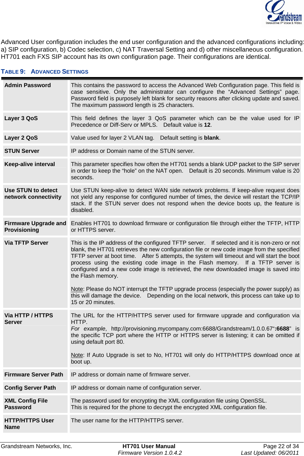
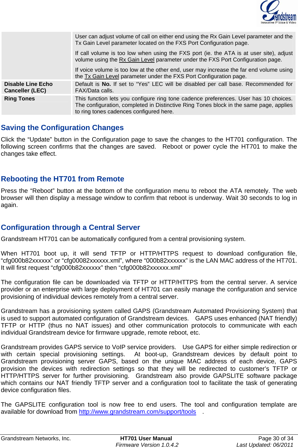
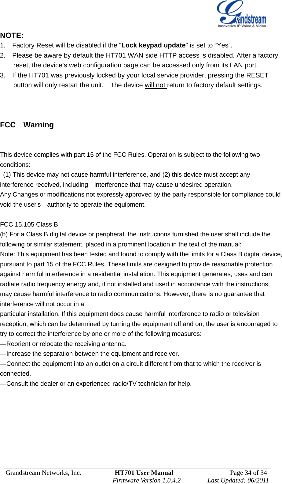
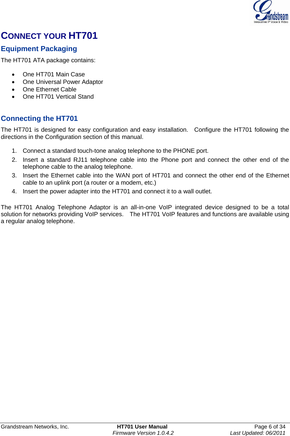
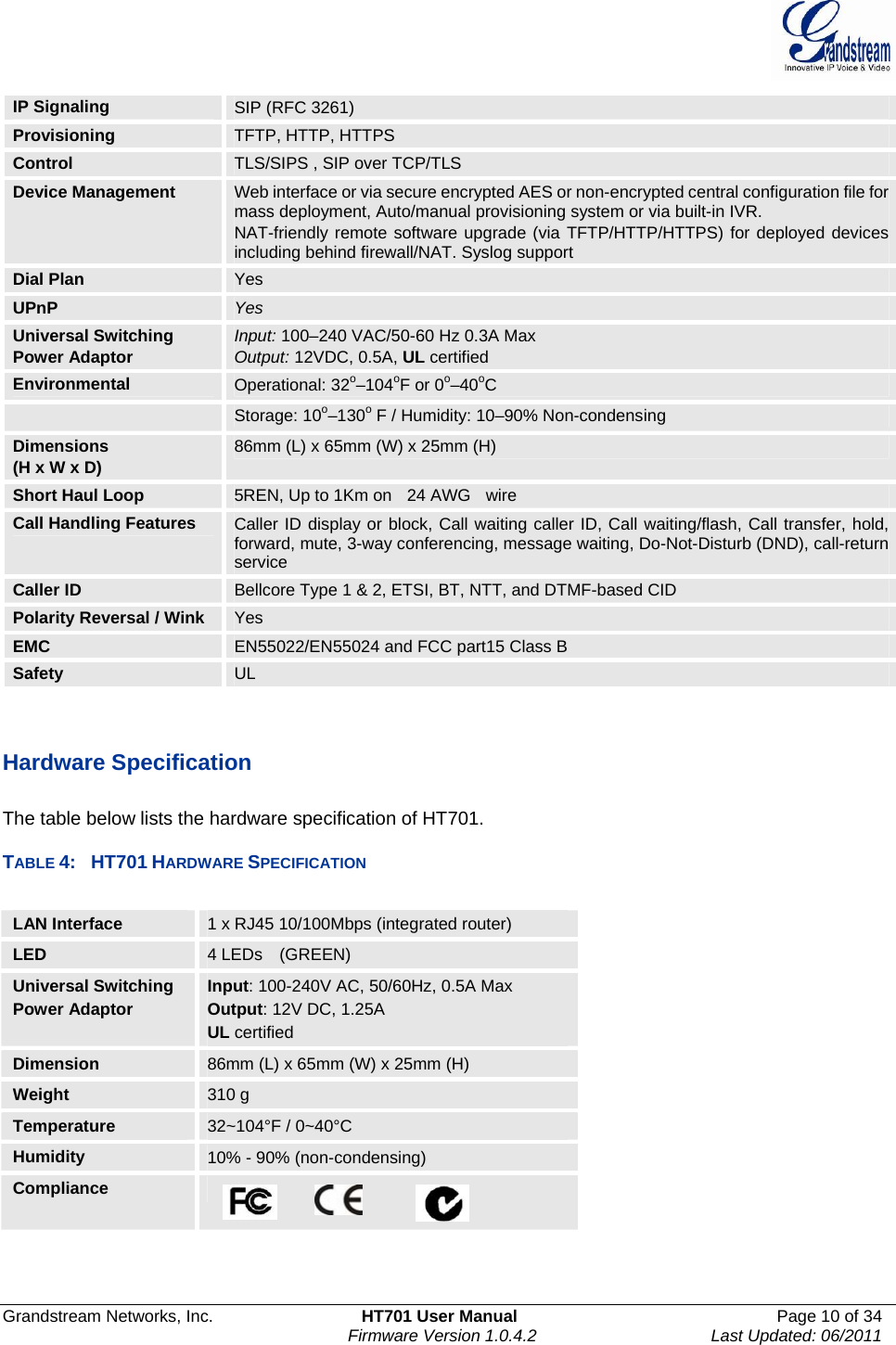
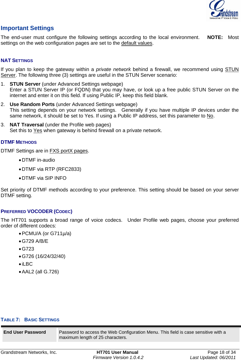
![Grandstream Networks, Inc. HT701 User Manual Page 23 of 34 Firmware Version 1.0.4.2 Last Updated: 06/2011 HTTP/HTTPS Password The password for the HTTP/HTTPS server. Firmware File Prefix Default is blank. If configured, HT701 will request firmware file with the prefix. This setting is useful for ITSPs. End user should keep it blank. Firmware File Postfix Default is blank. End user should keep it blank. Config File Prefix Default is blank. End user should keep it blank. Config File Postfix Default is blank. End user should keep it blank. Allow DHCP Option 66 to override server If set to “Yes”, configuration and upgrade server information can be obtained using DHCP option 66 from DHCP server located in customer’s environment. Automatic Upgrade Choose “Yes” to enable automatic upgrade and provisioning. If select “Check everyminutes” input the amount of minutes you want it to check for update. If select “Yes, daily at hour” make sure to input the hour of the day you want it to check for update, e.g. for 11 pm type 23. If select “Yes, weekly on day” make sure you input the day of the week (in format 0-6, 0 is Sunday) you want it to check for update. When set to No, HT701 will only do the following option you select; “Always check for New Firmware at Boot up” will check for new firmware every time the device reboots. “Check New Firmware only when F/W pre/suffix changes” will check for updates only when the pre/suffix has been changed. Firmware Key Used for firmware encryption. Should be 32 digit in hexadecimal representation. End user should keep it blank. Authenticate Conf File If set to Yes, config file is authenticated before acceptance. This protects the configuration from an unauthorized change. Firmware Key Used for firmware encryption. Should be 32 digit in hexadecimal representation. End user should keep it blank. SSL Certificate The user specify SSL certificate used for SIP over TLS in X.509 format. SSL Private Key The user specify SSL private key used for SIP over TLS in X.509 format. SSL Private Key Password User specify password to protect the private key above. ACS URL User specify the Auto Configuration Server’s URL (TR-069 protocol) ACS Username User specify the ACS Username ACS Password User specify the ACS password Periodic Inform Enable Default is No. If set to YES, device will send inform packets to the ACS Periodic Inform Interval Frequency that the inform packets will be sent out to the ACS Connection Request Username Set a user name for the ACS to connect to this device Connection Request Password Set a password for the ACS to connect to this device System Ring Cadence Configuration option is set ring cadence on all FXS ports for all incoming calls. (Syntax: c=on1/off1-on2/off2-on3/off3; [...]) Default is set to c=2000/4000; (US standards)](https://usermanual.wiki/Grandstream-Networks/HT701/User-Guide-1595349-Page-23.png)
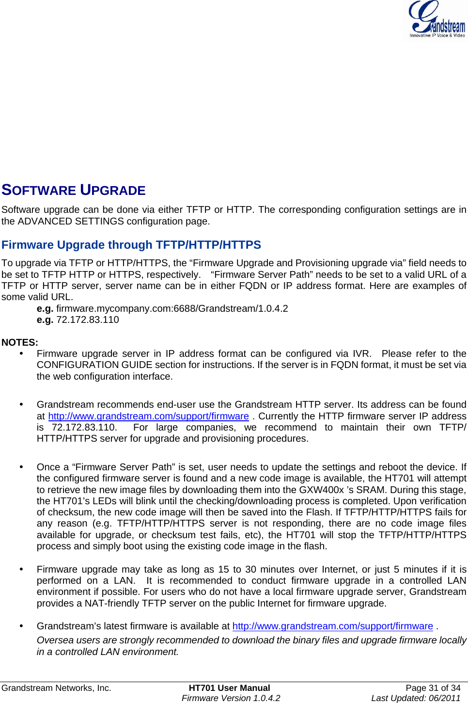
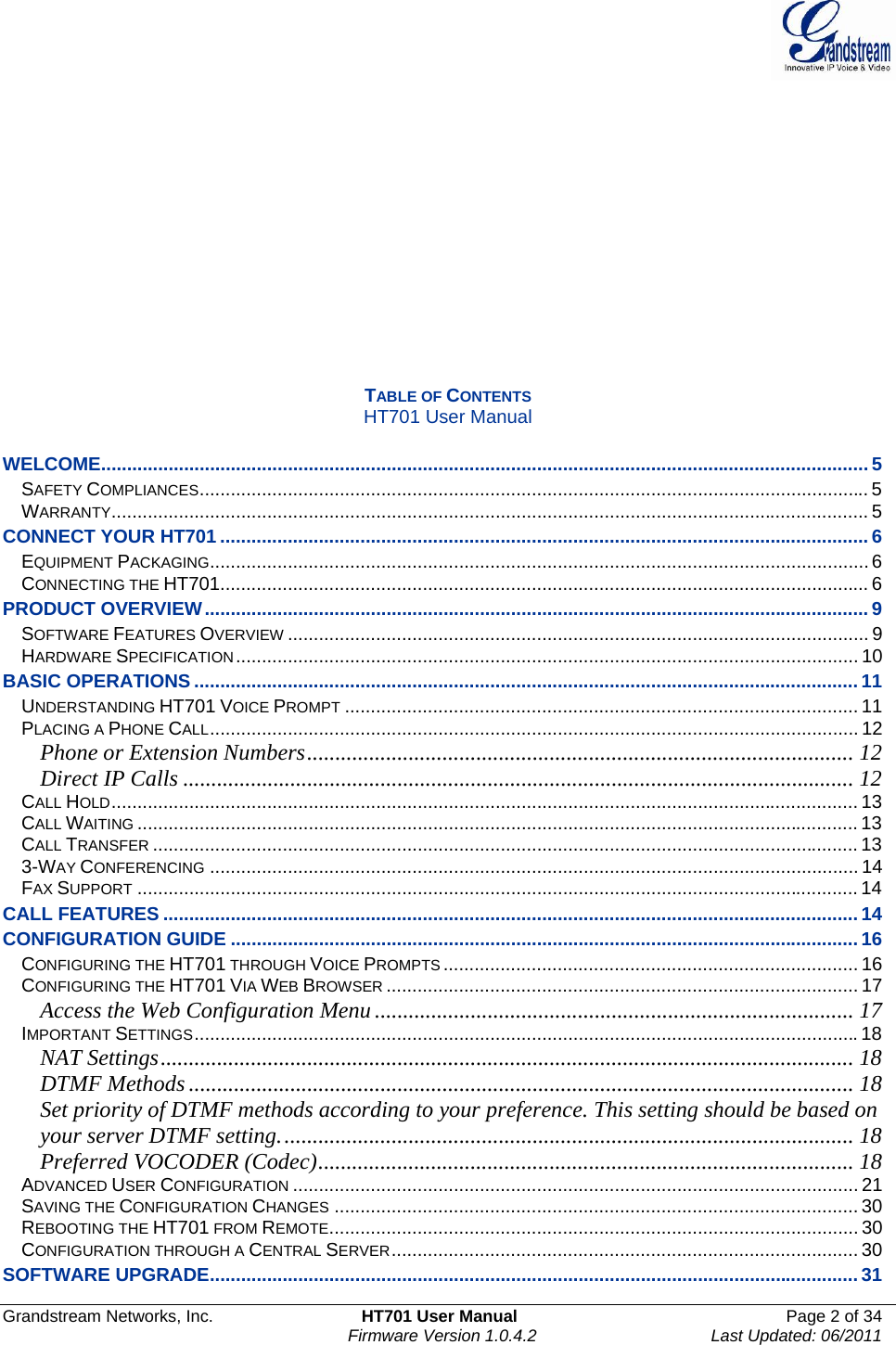
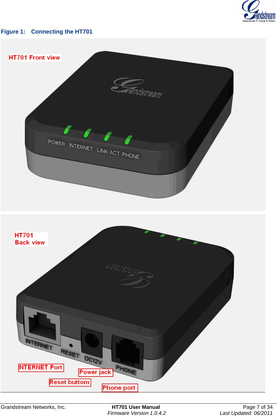
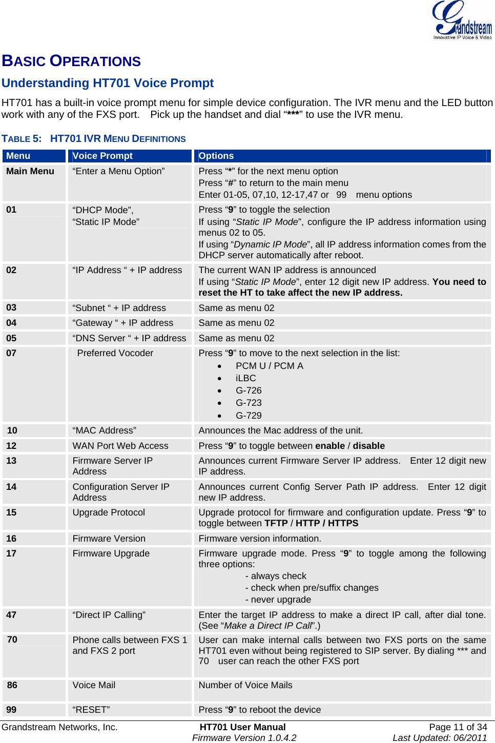
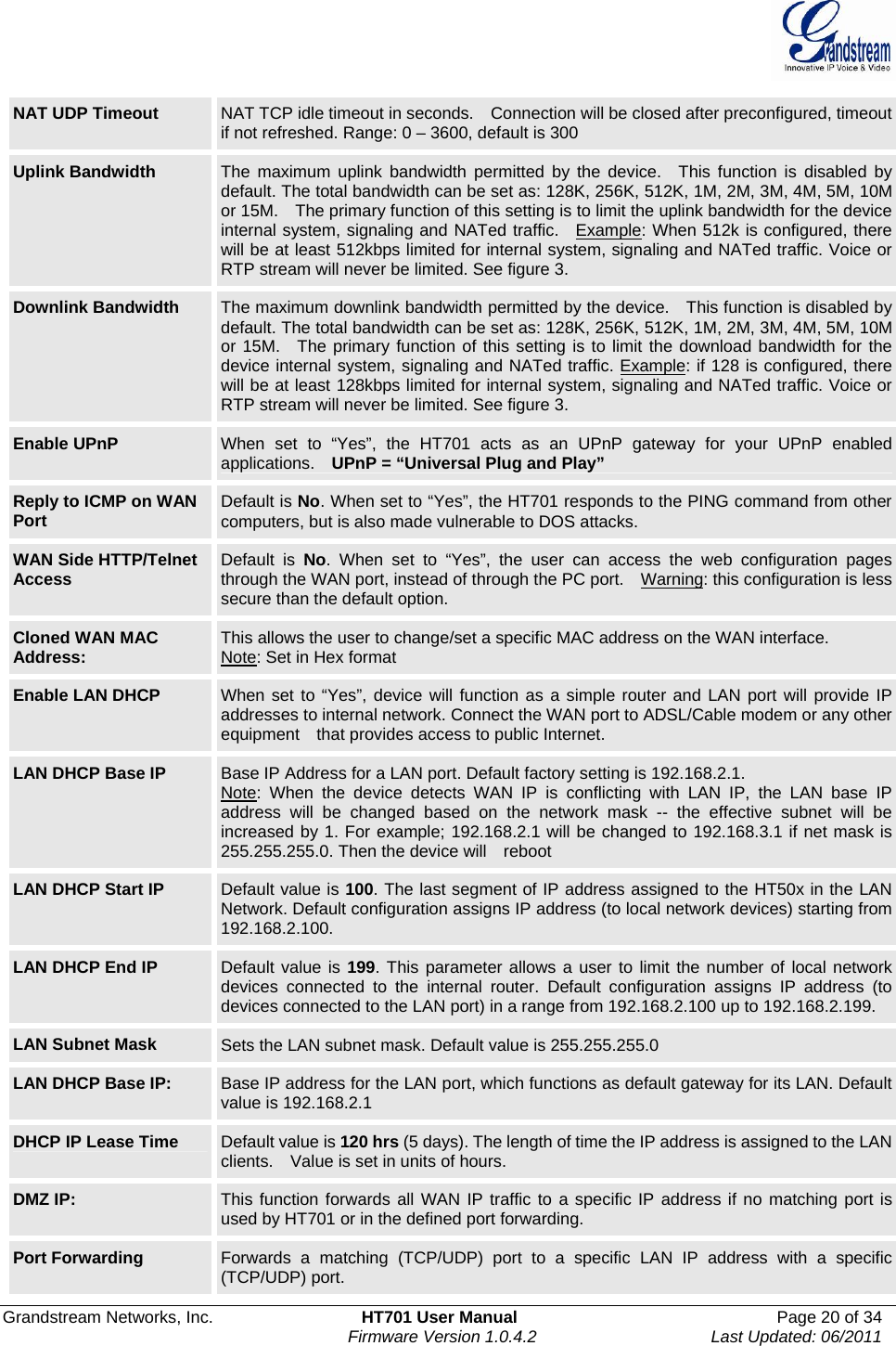
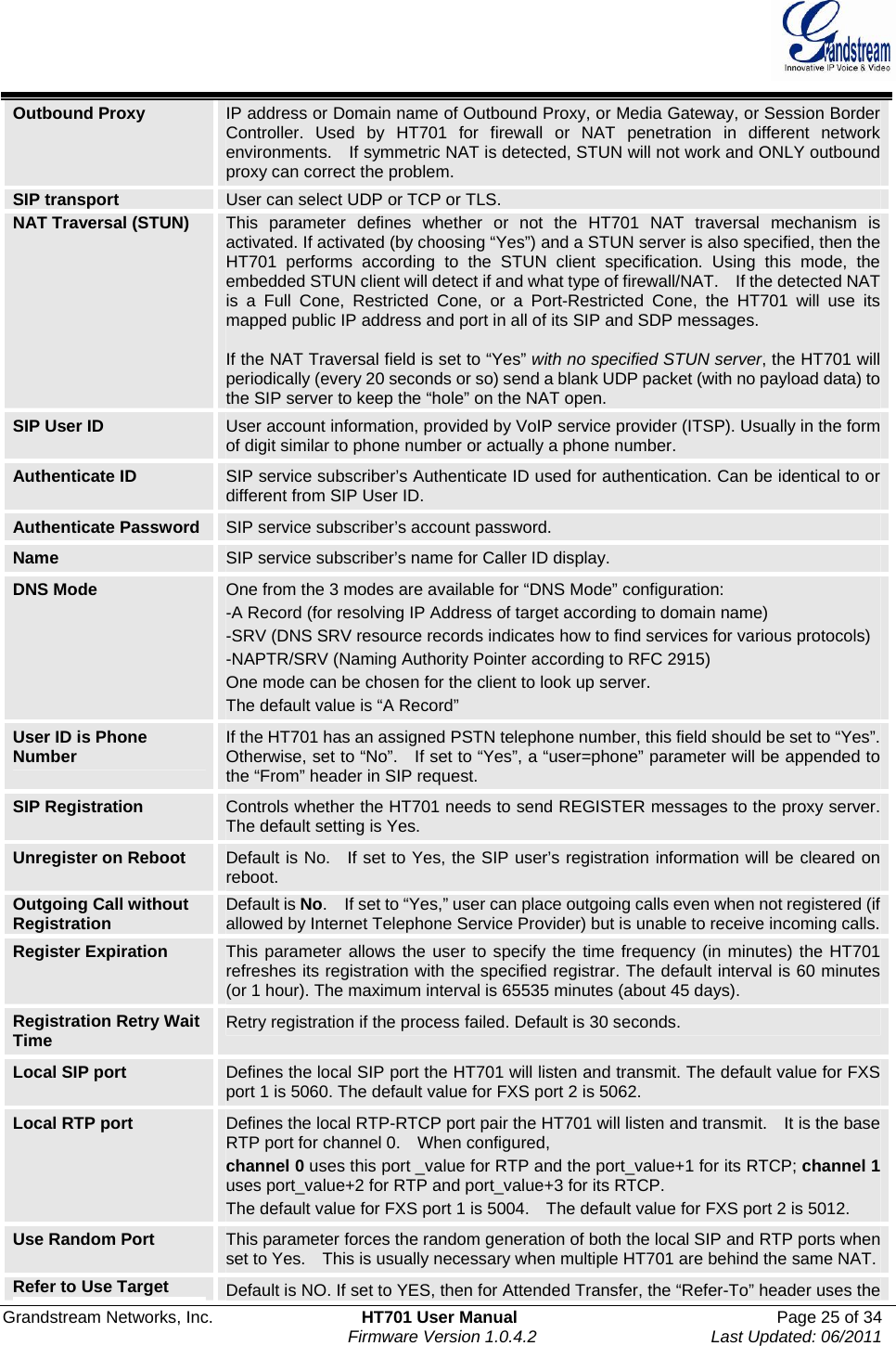
![Grandstream Networks, Inc. HT701 User Manual Page 24 of 34 Firmware Version 1.0.4.2 Last Updated: 06/2011 Call Progress Tones Using these settings, users can configure tone frequencies and cadence according to their preference. By default they are set to North American frequencies. Configure these settings with known values to avoid uncomfortable high pitch sounds. ON is the period of ringing (“On time” in ‘ms’) while OFF is the period of silence. In order to set a continuous tone, OFF should be zero. Otherwise it will ring ON ms and a pause of OFF ms and then repeat the pattern. Example configuration for N.A. Dialtone: f1=350@-13,f2=440@-13,c=0/0; Syntax: f1=freq@vol, f2=freq@vol, c=on1/off1-on2/off2-on3/off3; [...] (Note: freq: 0 - 4000Hz; vol: -30 - 0dBm) Lock Keypad Update If set to “Yes”, the configuration update via keypad is disabled. Disable Voice Prompt Default is No. Disables the voice prompt configuration. Disable Direct IP Call Default is No. Disables the Direct IP Call function. NTP server URI or IP address of the NTP (Network Time Protocol) server. This parameter synchronizes the date and time. Syslog Server The IP address or URL of System log server. This feature is especially useful for the ITSP (Internet Telephone Service Provider) Syslog Level Select the HT701 to report the log level. Default is NONE. The level is one of DEBUG, INFO, WARNING or ERROR. Syslog messages are sent based on the following events: 1. product model/version on boot up (INFO level) 2. NAT related info (INFO level) 3. sent or received SIP message (DEBUG level) 4. SIP message summary (INFO level) 5. inbound and outbound calls (INFO level) 6. registration status change (INFO level) 7. negotiated codec (INFO level) 8. Ethernet link up (INFO level) 9. SLIC chip exception (WARNING and ERROR levels) 10. memory exception (ERROR level) The Syslog uses USER facility. In addition to standard Syslog payload, it contains the following components: GS_LOG: [device MAC address][error code] error message Example: May 19 02:40:38 192.168.1.14 GS_LOG: [00:0b:82:00:a1:be][000] Ethernet link is up Download Device Configuration Allows user to download and save a text file containing all the P values of each setting as configured at that point on the unit. TABLE 10: ACCOUNT SETTINGS Profile Active When set to Yes the FXS port is activated. Primary SIP Server SIP Server’s IP address or Domain name provided by VoIP service provider. Failover SIP Server Failover SIP Server’s IP address or Domain name in case primary server does not respond. Prefer Primary SIP Server Default is no. If set to yes it will register to Primary Server if registration with Failover server expires](https://usermanual.wiki/Grandstream-Networks/HT701/User-Guide-1595349-Page-24.png)
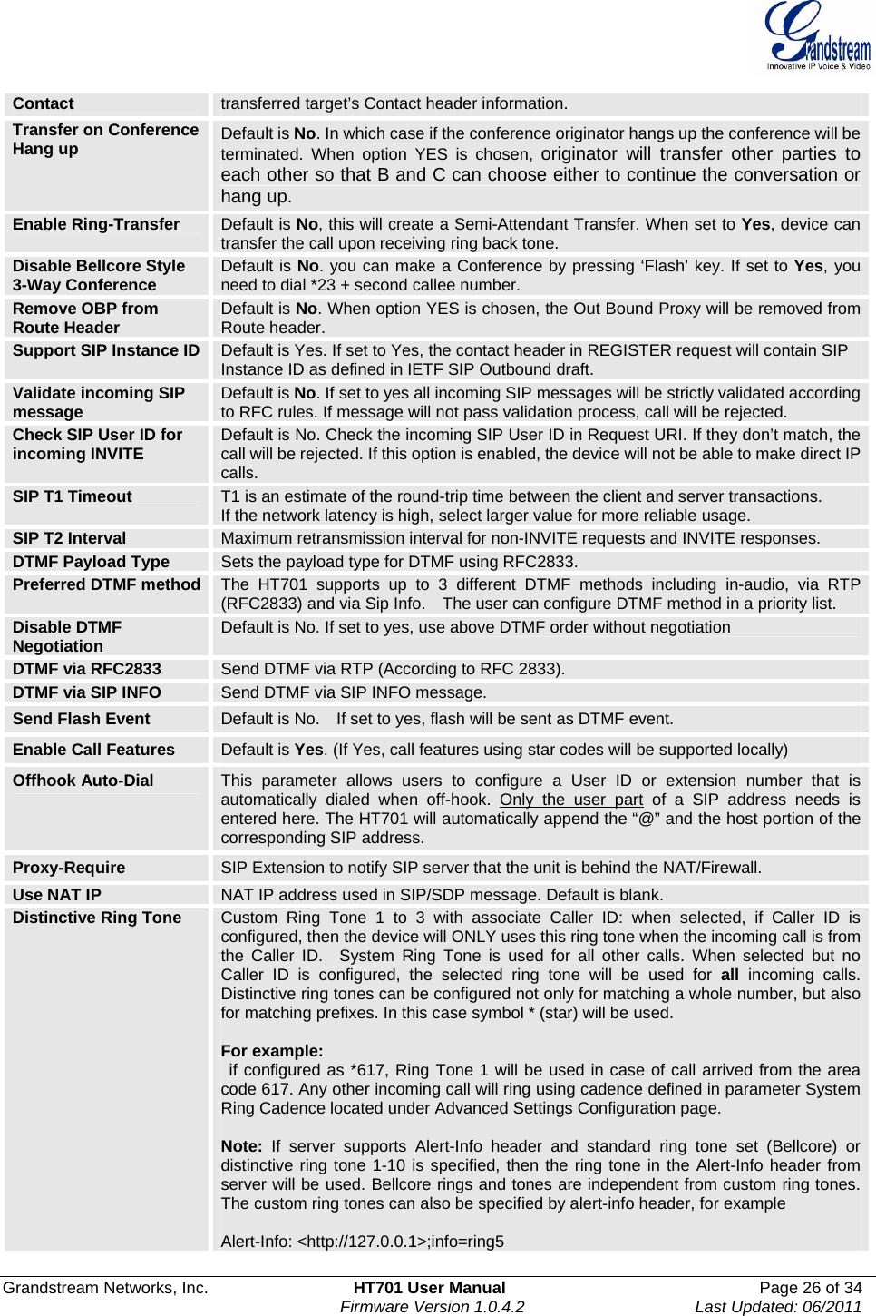
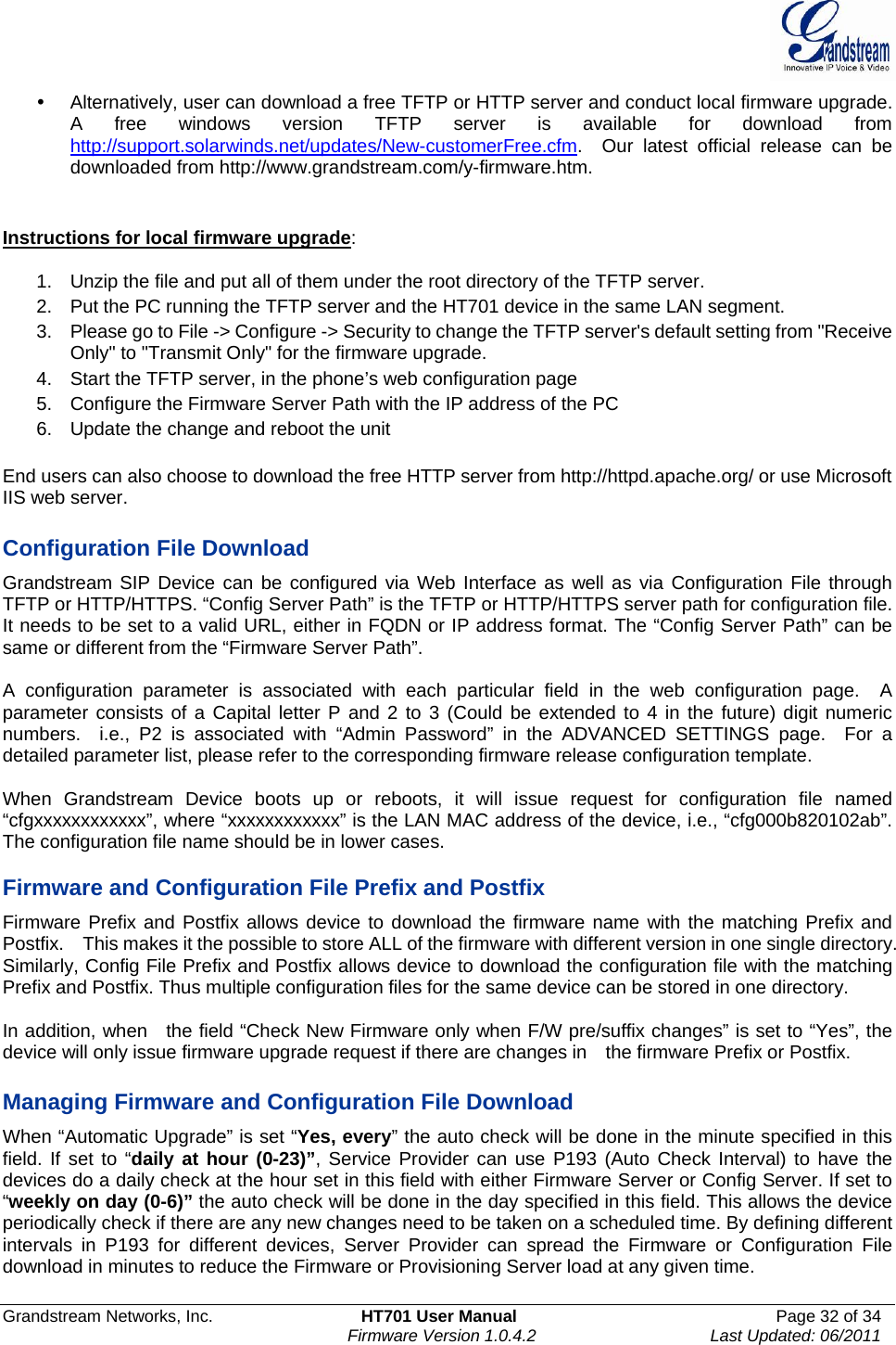
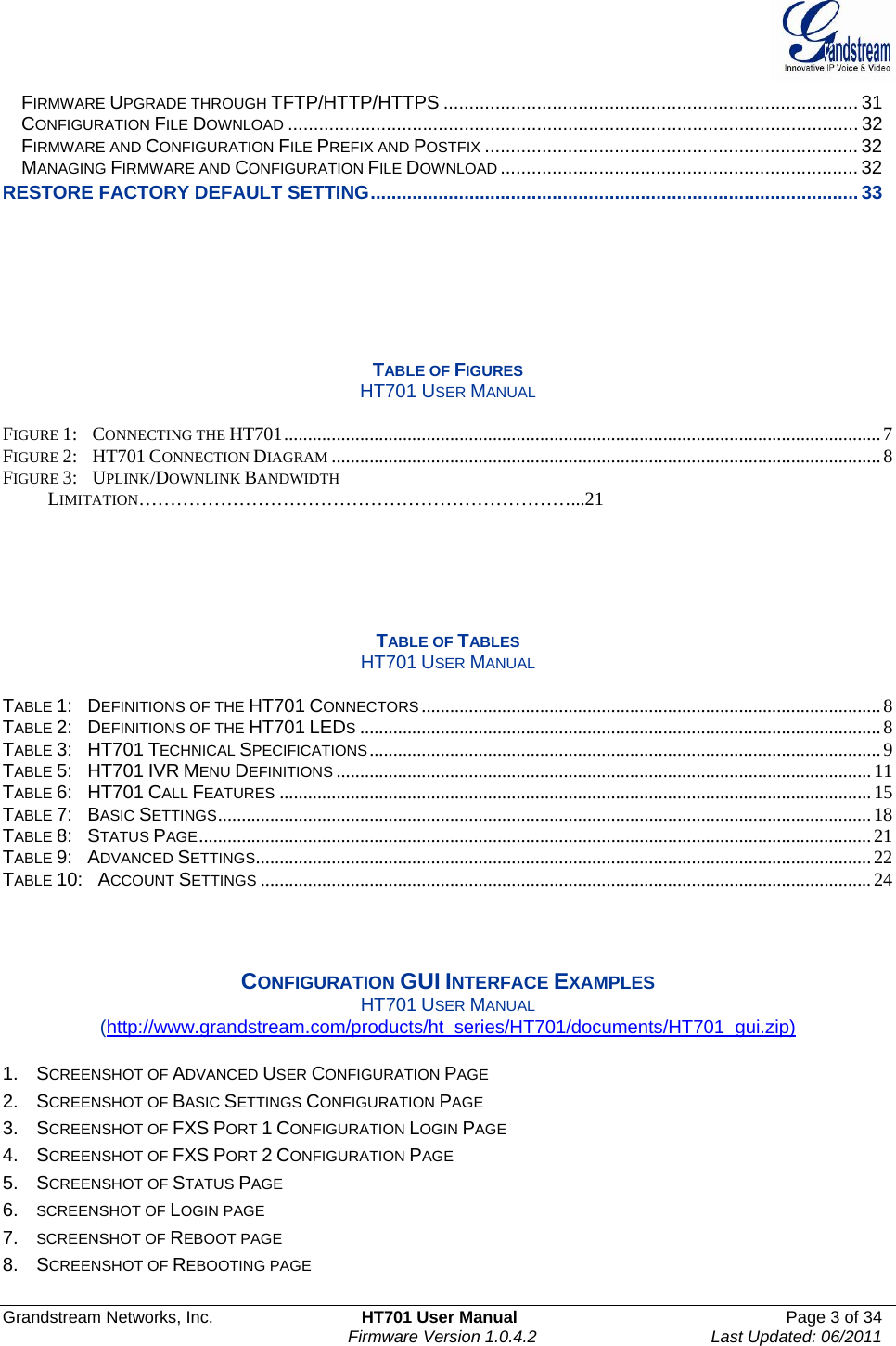
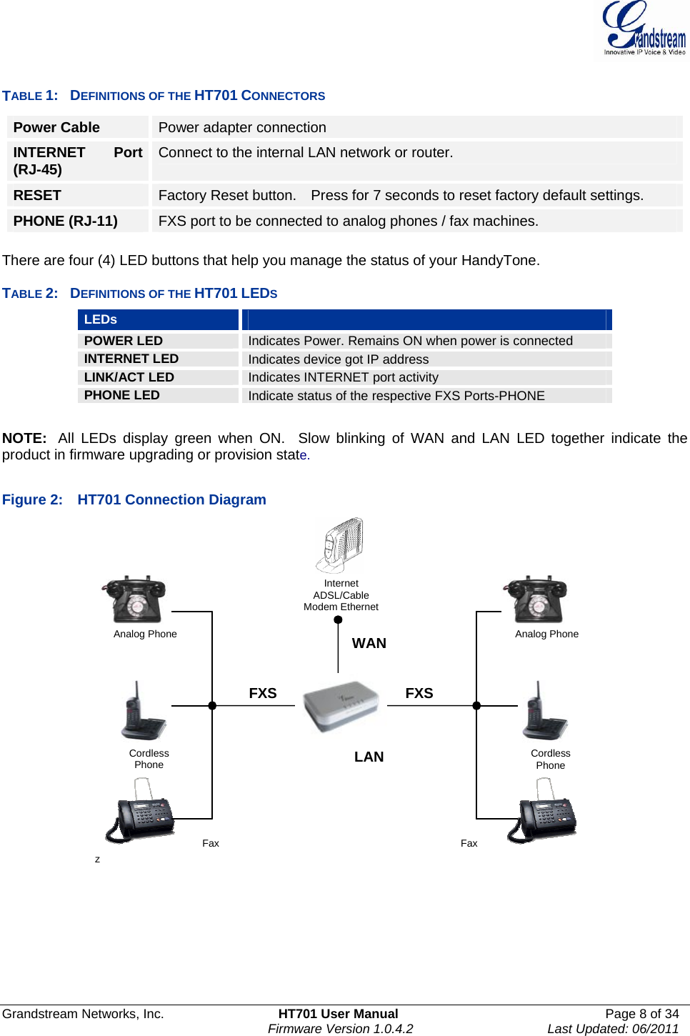
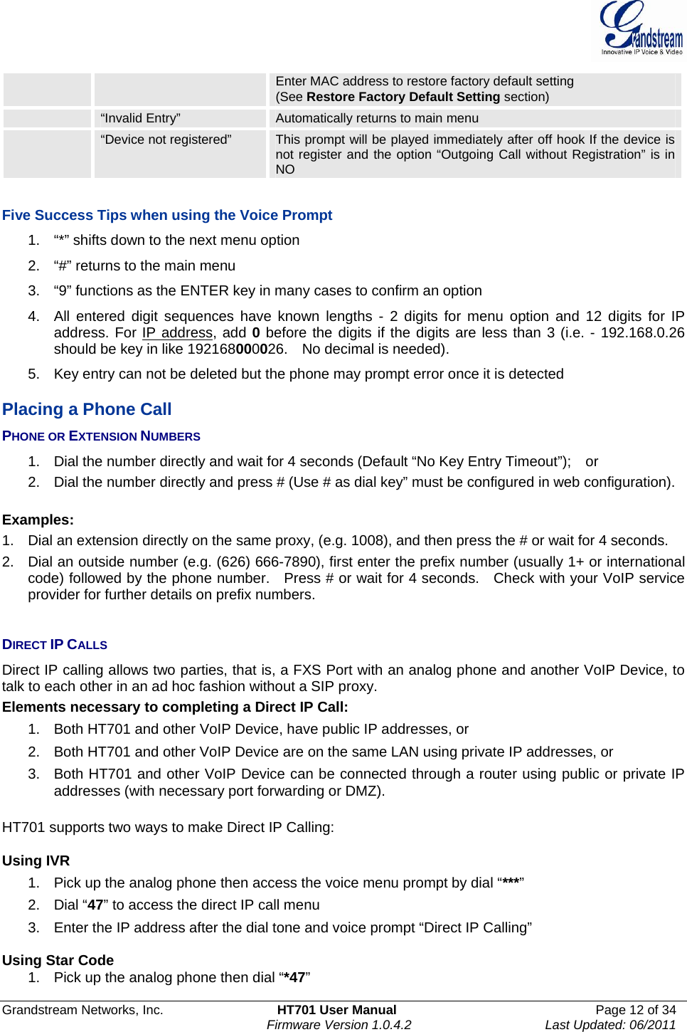
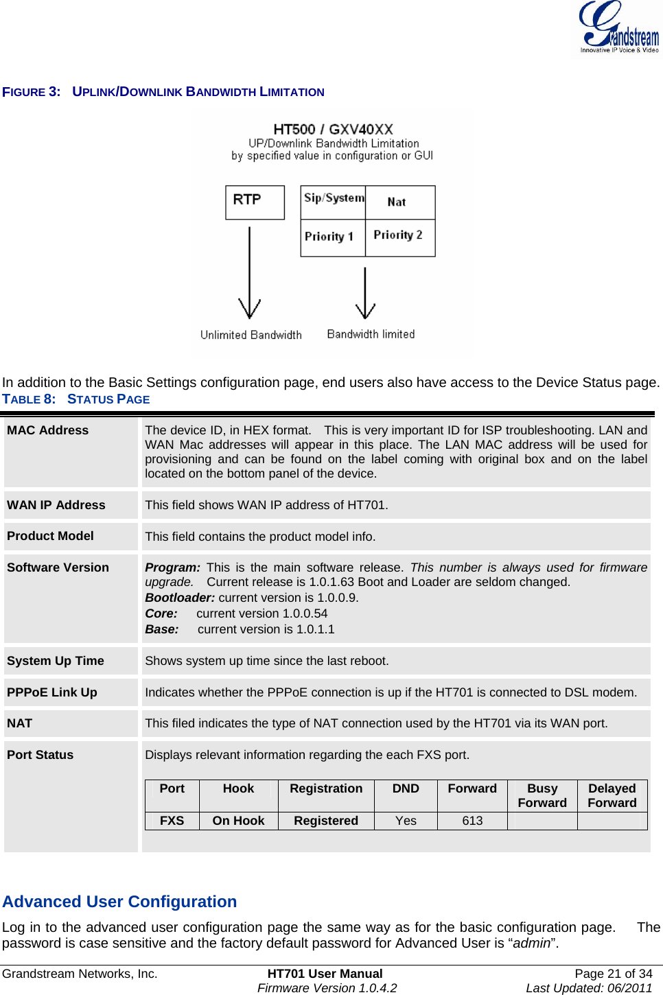
![Grandstream Networks, Inc. HT701 User Manual Page 27 of 34 Firmware Version 1.0.4.2 Last Updated: 06/2011 Disable Call Waiting Default is No. If set to YES Call Waiting indication information will not be provided to analog phone connected to this FXS port. Disable Call-Waiting Caller ID Default is No. If set to YES Call Waiting caller ID will not be provided to analog phone connected to this FXS port. Disable Call Waiting Tone Default is No. This is to disable the stutter Call Waiting Tone when a Call Waiting information arrives. The CWCID information will still be displayed. Disable Reminder Ring for On-Hold Call Default is No. Do not play the reminder ring when this is set to Yes. Disable Visual MWI If set to “Yes”, the MWI information will not be transferred to the analog phone connected to the FXS port. Ring Timeout Incoming call will stop ringing when not picked up given a specific period of time. Delayed Call Forward Wait Time Default value is 20 seconds. In case this feature activated using * codes (*92 code), the call will be forwarded after this preconfigured amount of time. No Key Entry Timeout Default is 4 seconds. Dialing process is completed and outgoing call is initiated if no key entry occurs during this preconfigured interval. Early Dial Default is No. Use only if proxy supports 484 response. This parameter controls whether the phone will send an early INVITE each time a key is pressed when a user dials a number. If set to “Yes”, an INVITE is sent using the dial-number collected thus far; Otherwise, no INVITE is sent until the “(Re-)Dial” button is pressed or after about 5 seconds have elapsed if the user forgets to press the “Re-Dial” button. The “Yes” option should be used ONLY if there is a SIP proxy configured and the proxy server supports 484 Incomplete Address response. Otherwise, the call will likely be rejected by the proxy (with a 404 Not Found error). This feature does NOT work with and should NOT be enabled for direct IP-to-IP calling.Dial Plan Prefix Sets the prefix added to each dialed number. Use # as Dial Key Allows users to configure the “#” key as the “Send” (or “Dial”) key. If set to “Yes”, “#” will send the number. In this case, this key is essentially equivalent to the “Dial” key. If set to “No”, this “#” key can be included as part of number. Dial Plan Dial Plan Rules: 1. Accept Digits: 1,2,3,4,5,6,7,8,9,0 , *, #, A,a,B,b,C,c,D,d 2. Grammar: x - any digit from 0-9; • xx+ - at least 2 digits number; • xx. – at least 1 digit number. • ^ - exclude; • [3-5] - any digit of 3, 4, or 5; • [147] - any digit 1, 4, or 7; • <2=011> - replace digit 2 with 011 when dialing • < =1> - add a leading 1 to all numbers dialed, vice versa will remove a 1 from the number dialed • | - or • Example 1: {[369]11 | 1617xxxxxxx} – Allow 311, 611, 911, and any 11 digit numbers with leading digits 1617 Example 2: {^1900x+ | <=1617>xxxxxxx} – Block any number of leading digits 1900 and add prefix 1617 for any dialed 7 digit numbers • Example 3: {1xxx[2-9]xxxxxx | <2=011>x+} –Allow any combinations of numbers with 11 digits which has a leading digit 1, but 5th digit cannot be 0 or 1. Or any length of numbers with a minimum of 2 digits beginning with 2, with the leading digit replaced with 011. 3. Default: Outgoing - {x+} Example of a simple dial plan used in a Home/Office in the US:](https://usermanual.wiki/Grandstream-Networks/HT701/User-Guide-1595349-Page-27.png)
![Grandstream Networks, Inc. HT701 User Manual Page 28 of 34 Firmware Version 1.0.4.2 Last Updated: 06/2011 { ^1900x. | <=1617>[2-9]xxxxxx | 1[2-9]xx[2-9]xxxxxx | 011[2-9]x. | [3469]11 } Explanation of example rule (reading from left to right): • ^1900x. - prevents dialing any number started with 1900 • <=1617>[2-9]xxxxxx - allows dialing to local area code (617) numbers by dialing 7 numbers and 1617 area code will be added automatically • 1[2-9]xx[2-9]xxxxxx |- allows dialing to any US/Canada Number with 11 digits length • 011[2-9]x. - allows international calls starting with 011 • [3469]11 - allow dialing special and emergency numbers 311, 411, 611 and 911 Note: In some cases user wishes to dial strings such as *123 to activate voice mail or other application provided by service provider. In this case * should be predefined inside dial plan feature and the Dial Plan should be: { *x+ }. Subscribe for MWI Default is No. When set to “Yes” a SUBSCRIBE for Message Waiting Indication will be sent periodically. Send Anonymous If this parameter is set to “Yes”, the “From” header along with Privacy and P_ Asserted_Identity headers in outgoing INVITE message will be set to anonymous, blocking Caller ID. Anonymous Call Rejection Default is No. If set to Yes, incoming calls with anonymous Caller ID will be rejected with 486 Busy message. Special Feature Default is Standard. Choose the selection to meet some special requirements from Softswitch vendors. Session Expiration Grandstream implemented SIP Session Timer. The session timer extension enables SIP sessions to be periodically “refreshed” via a SIP request (UPDATE, or re-INVITE. Once the session interval expires, if there is no refresh via a UPDATE or re-INVITE message, the session will be terminated. Session Expiration is the time (in seconds) at which the session is considered timed out, if no successful session refresh transaction occurs beforehand. The default value is 180 seconds. Min-SE The minimum session expiration (in seconds). The default value is 90 seconds. Caller Request Timer If selecting “Yes” the phone will use session timer when it makes outbound calls if remote party supports session timer. Callee Request Timer If selecting “Yes” the phone will use session timer when it receives inbound calls with session timer request. Force Timer If selecting “Yes” the phone will use session timer even if the remote party does not support this feature. Selecting “No” will allow the phone to enable session timer only when the remote party support this feature. To turn off Session Timer, select “No” for Caller Request Timer, Callee Request Timer, and Force Timer. UAC Specify Refresher As a Caller, select UAC to use the phone as the refresher, or UAS to use the Callee or proxy server as the refresher. UAS Specify Refresher As a Callee, select UAC to use caller or proxy server as the refresher, or UAS to use the phone as the refresher. Force INVITE Session Timer can be refreshed using INVITE method or UPDATE method. Select “Yes” to use INVITE method to refresh the session timer. Send Re-INVITE After Fax Default is No, If set to “Yes”, device will send an INVITE with audio vocoders upon completion of Fax to continue session in audio only. Use First Matching Vocoder in 200OK SDP Default is No. If set to “Yes”, device will include only the first match vocoder in its 200OK response, otherwise it will include all match vocoders in same order received in INVITE.Preferred Vocoder The HT701 supports up to 5 different Vocoder types including G.711 A-/U-law, G.726 (Supports bit rates 16, 24, 32 and 40), G.723.1, G.729A/B/E, iLBC and AAL2. The user can configure Vocoders in a preference list that will be included with the same preference order in SDP message. The first Vocoder is entered by choosing the appropriate option in “Choice 1”. The last Vocoder is entered by choosing the appropriate option in “Choice 8”. Vocoder types can also be changed per call basis by using a star code. Please see the](https://usermanual.wiki/Grandstream-Networks/HT701/User-Guide-1595349-Page-28.png)