Grandstream Networks HT818 Analong Telephone Adapter User Manual User Guide
Grandstream Networks, Inc. Analong Telephone Adapter User Guide
UserManual.wiki
>
Grandstream Networks
>
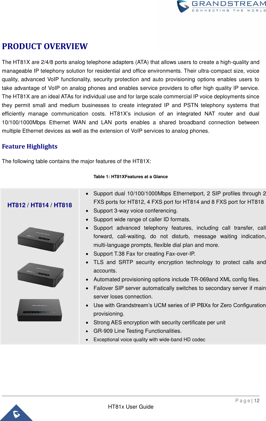
HT818 User Manual
User Guide
Navigation menu
Upload a User Manual
Namespaces
Wiki Guide
HTML
PDF
Info
Views
User Manual
Discussion / Help
Navigation


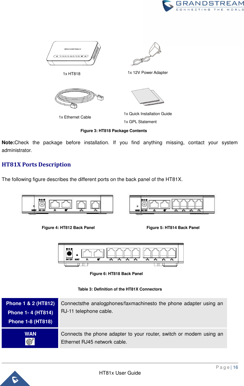
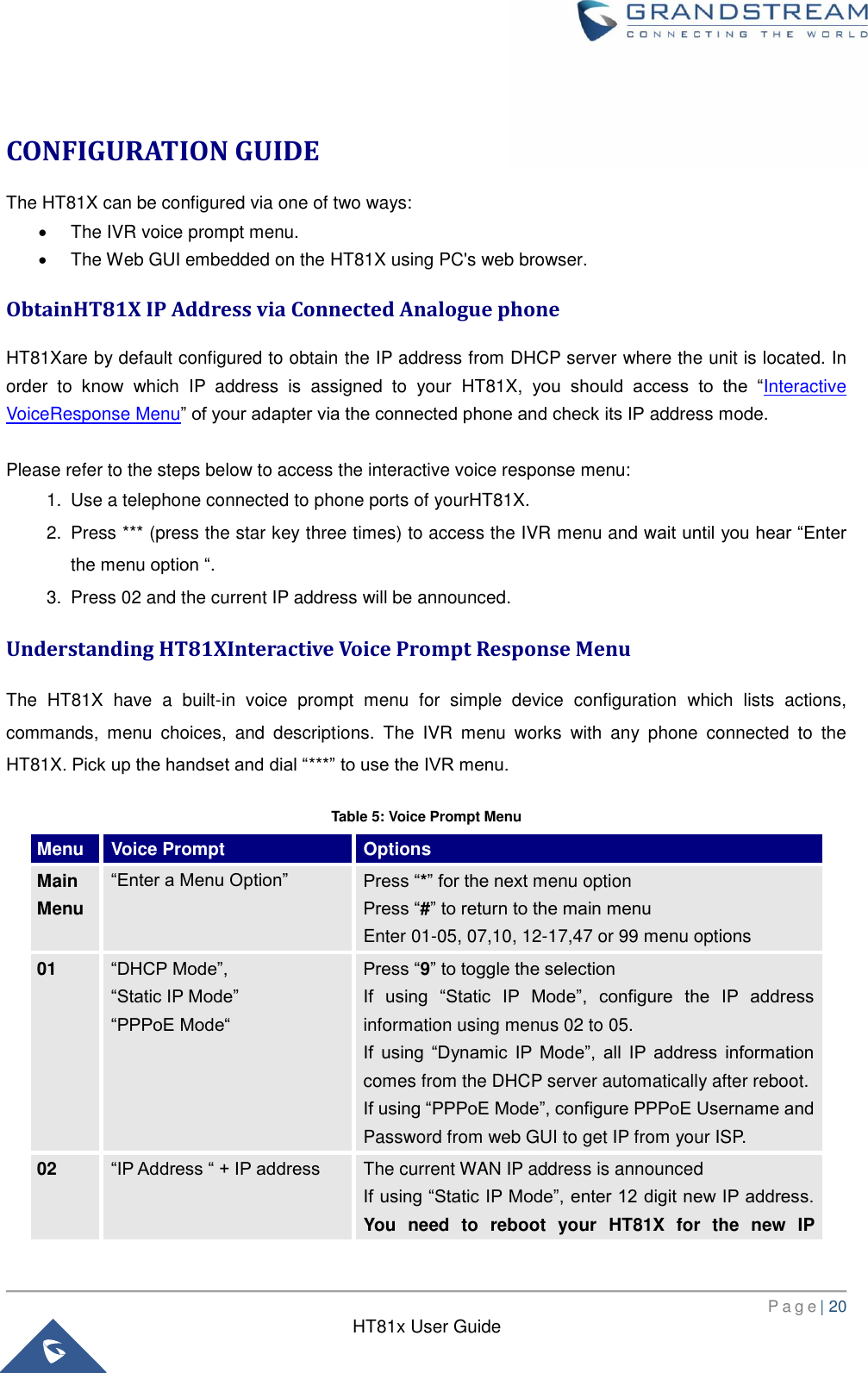
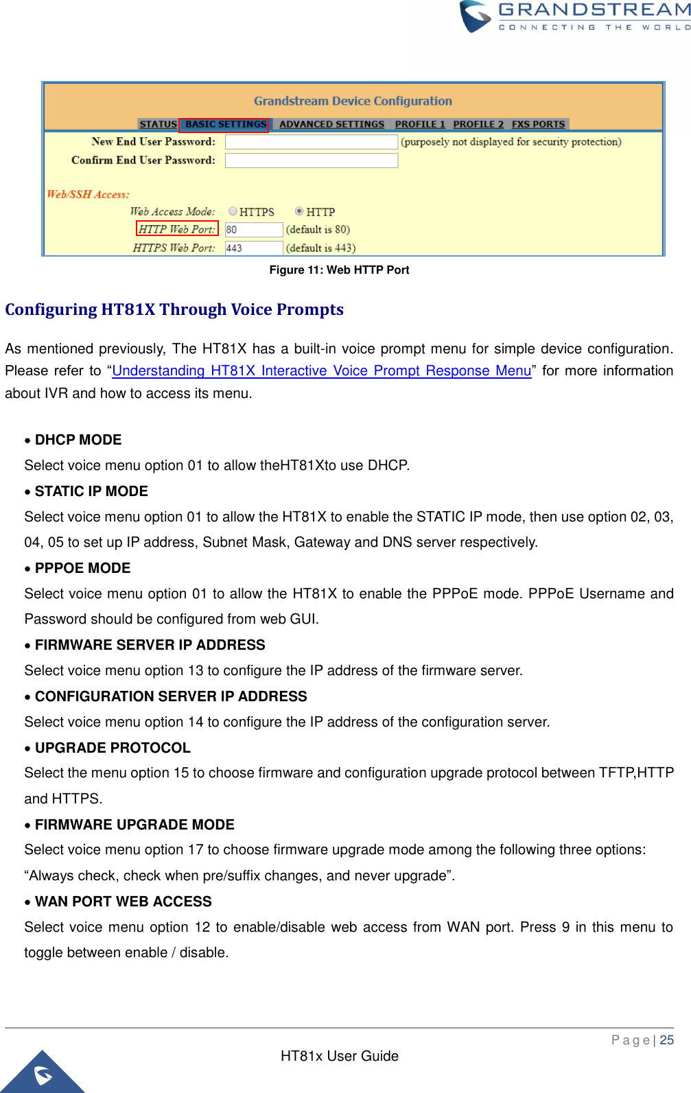
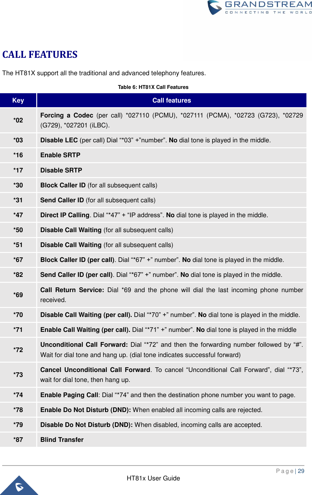
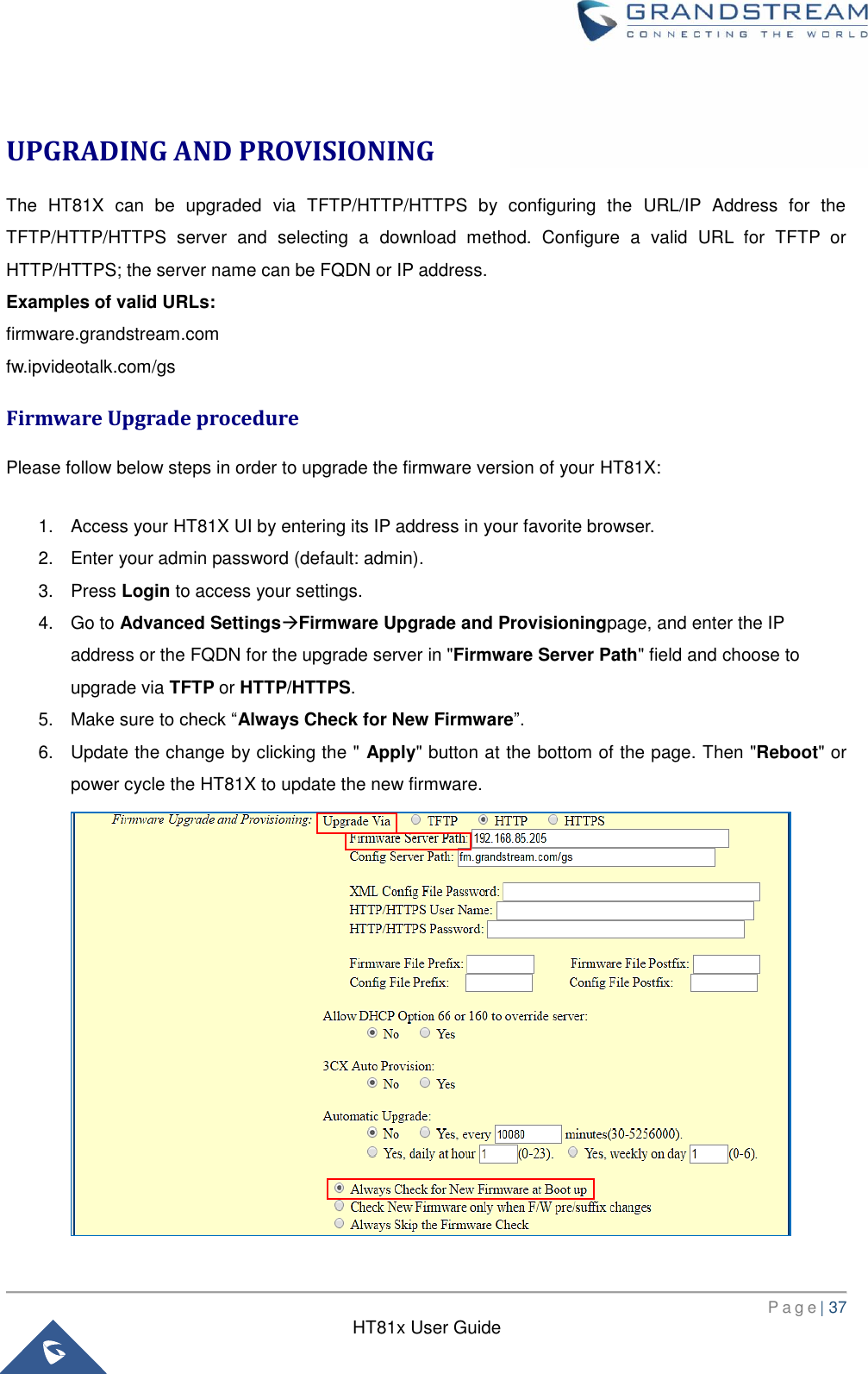
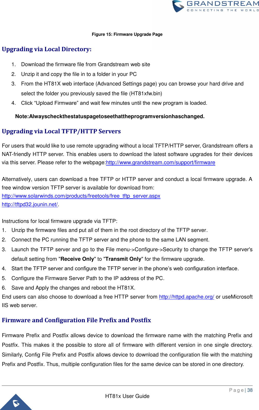
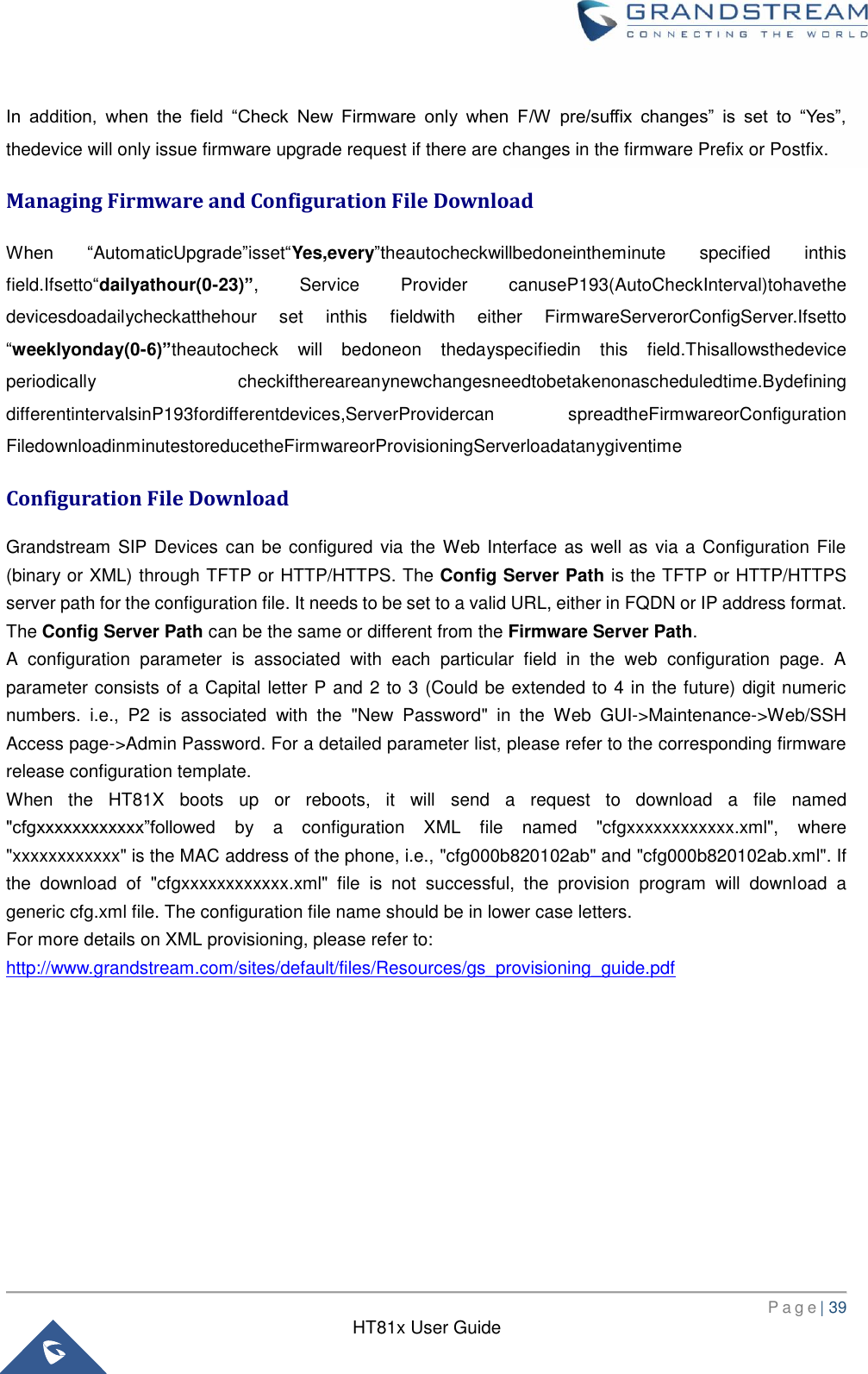
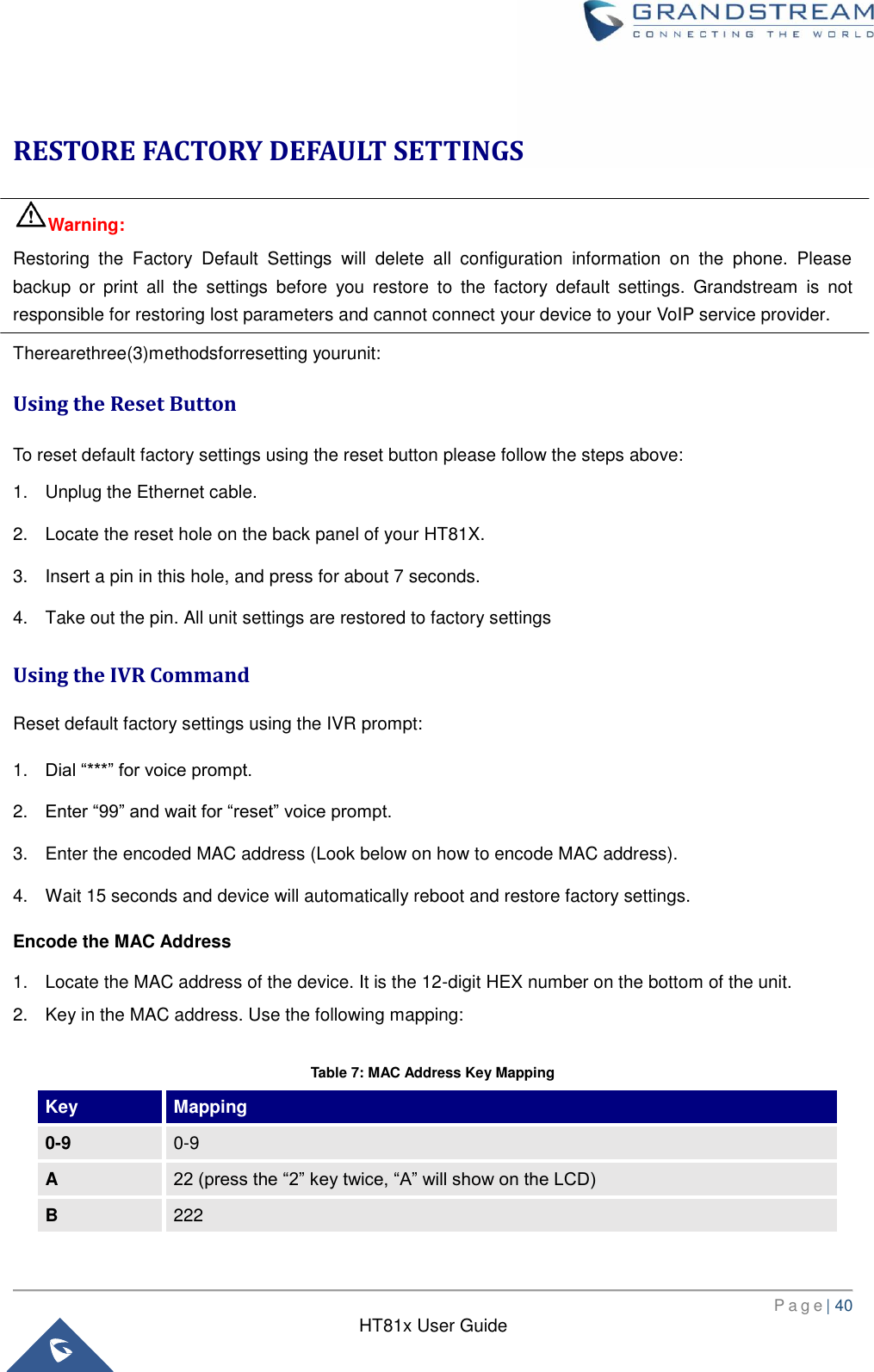
![P a g e | 24 HT81x User Guide Changing Admin Level Password 1. Access your HT81X web UI by entering its IP address in your favorite browser. 2. Enter your admin password (default: admin). 3. Press Login to access your settings. 4. Go to Advanced Settings New Admin Password and enter the new admin password. 5. Confirm the new admin password. 6. Press Apply at the bottom of the page to save your new settings. Figure 9: Admin Level Password Changing User Level Password 1. Access your HT81X web UI by entering its IP address in your favorite browser. 2. Enter your admin password (default: admin). 3. Press Login to access your settings. 4. Go to Basic Settings New End User Password and enter the new end-user password. 5. Confirm the new end-user password. 6. Press Apply at the bottom of the page to save your new settings. Figure 10: User Level Password Changing HTTP Web Port 1. Access your HT81Xweb UIby entering its IP address in your favorite browser. 2. Enter your admin password (default: admin). 3. Press Login to access your settings. 4. Go to Basic SettingsHTTPWeb Port. 5. Make sure that the Web Access Mode is set to HTTP. 6. Change the current port to your desired/new HTTP port. Ports accepted are in range [1-65535]. 7. Press Apply at the bottom of the page to save your new settings](https://usermanual.wiki/Grandstream-Networks/HT818/User-Guide-3625164-Page-25.png)