Grandstream Networks UCM6208 IP PBX User Manual 1 UCM62xx usermanual ok
Grandstream Networks, Inc. IP PBX 1 UCM62xx usermanual ok
UserManual.wiki
>
Grandstream Networks
>
UCM6208 User Manual
>
Users Manual Part One
Contents
1.
Users Manual Part One
2.
Users Manual Part Two
Users Manual Part One
Navigation menu
Upload a User Manual
Namespaces
Wiki Guide
HTML
PDF
Info
Views
User Manual
Discussion / Help
Navigation


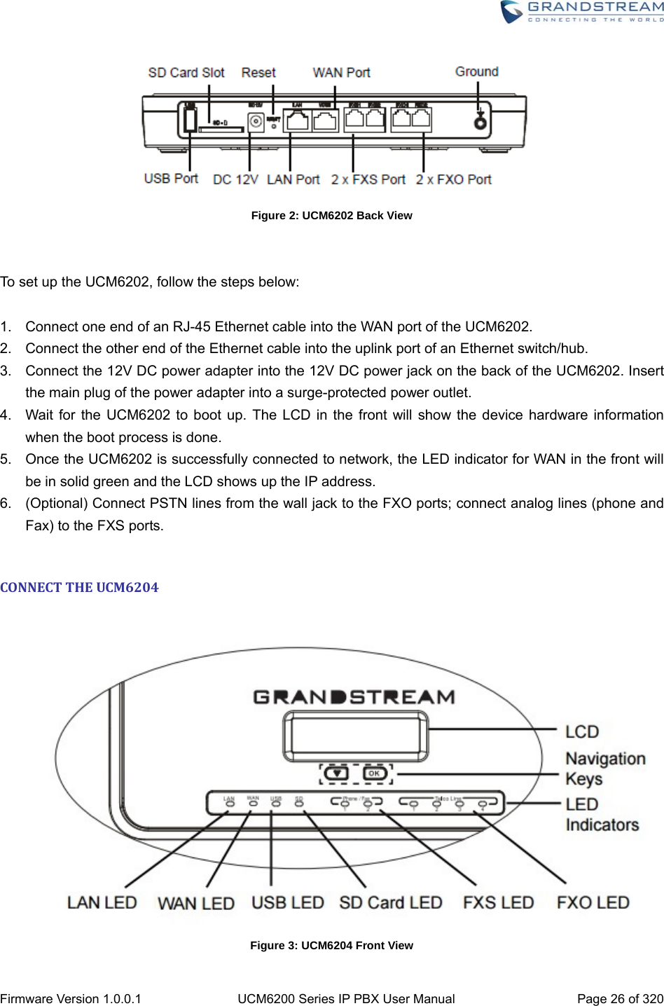
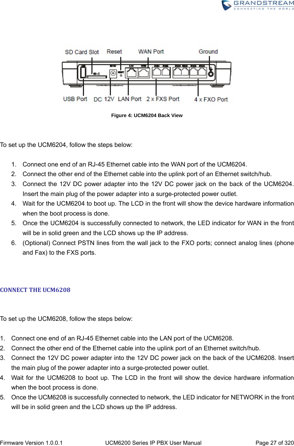

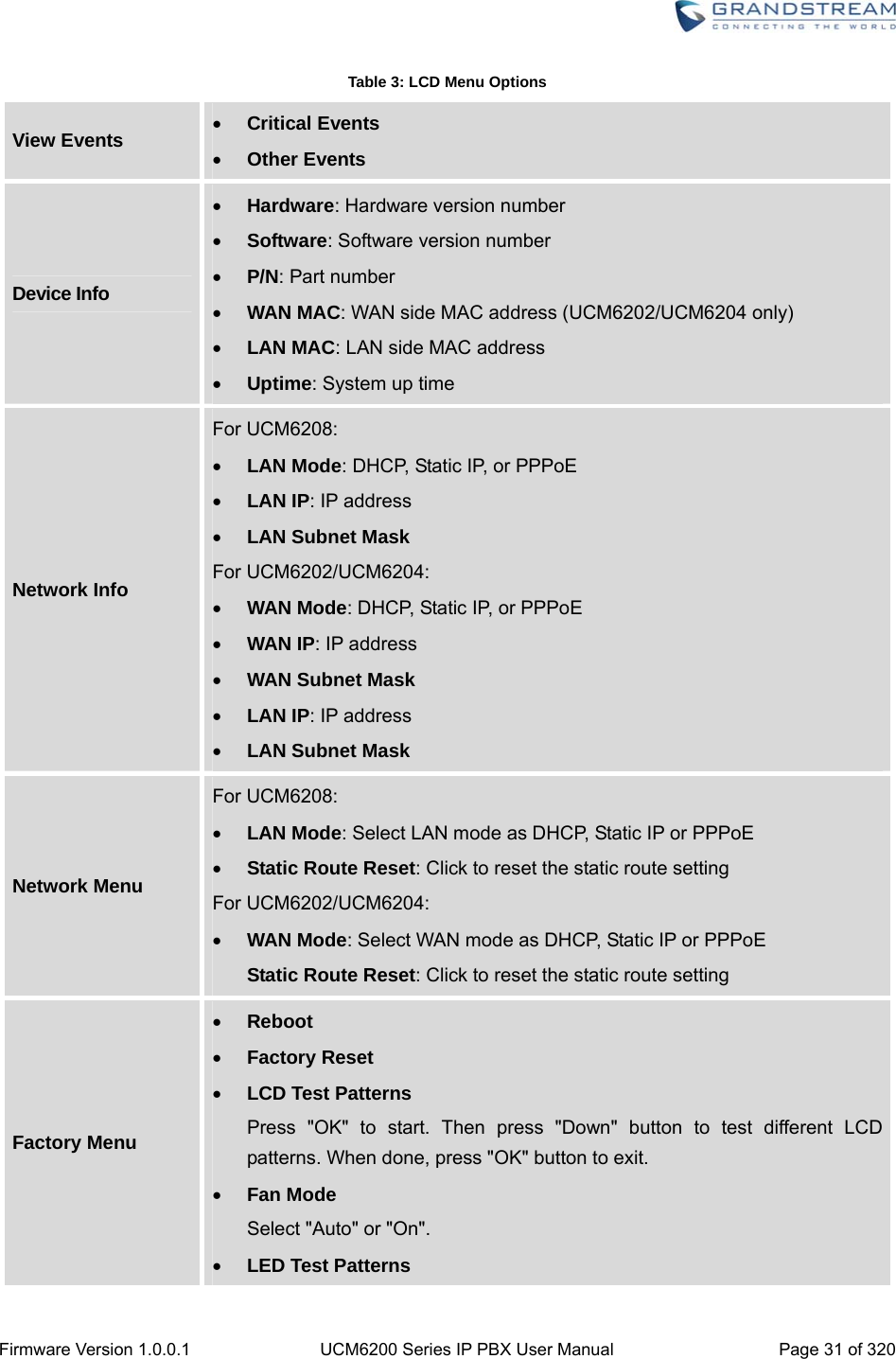
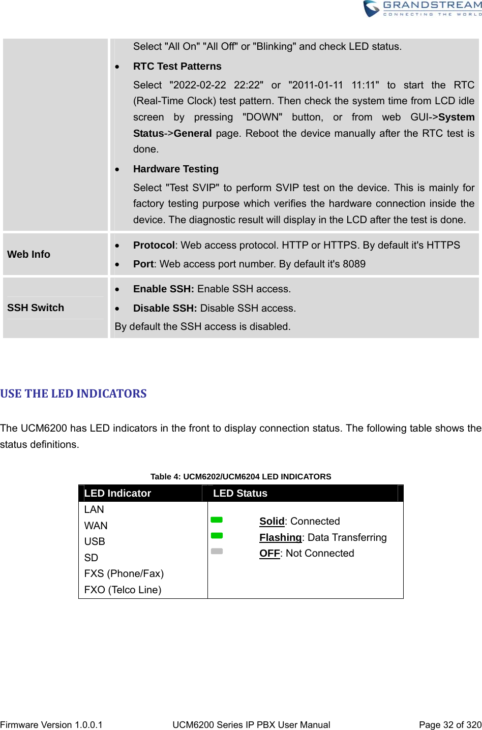
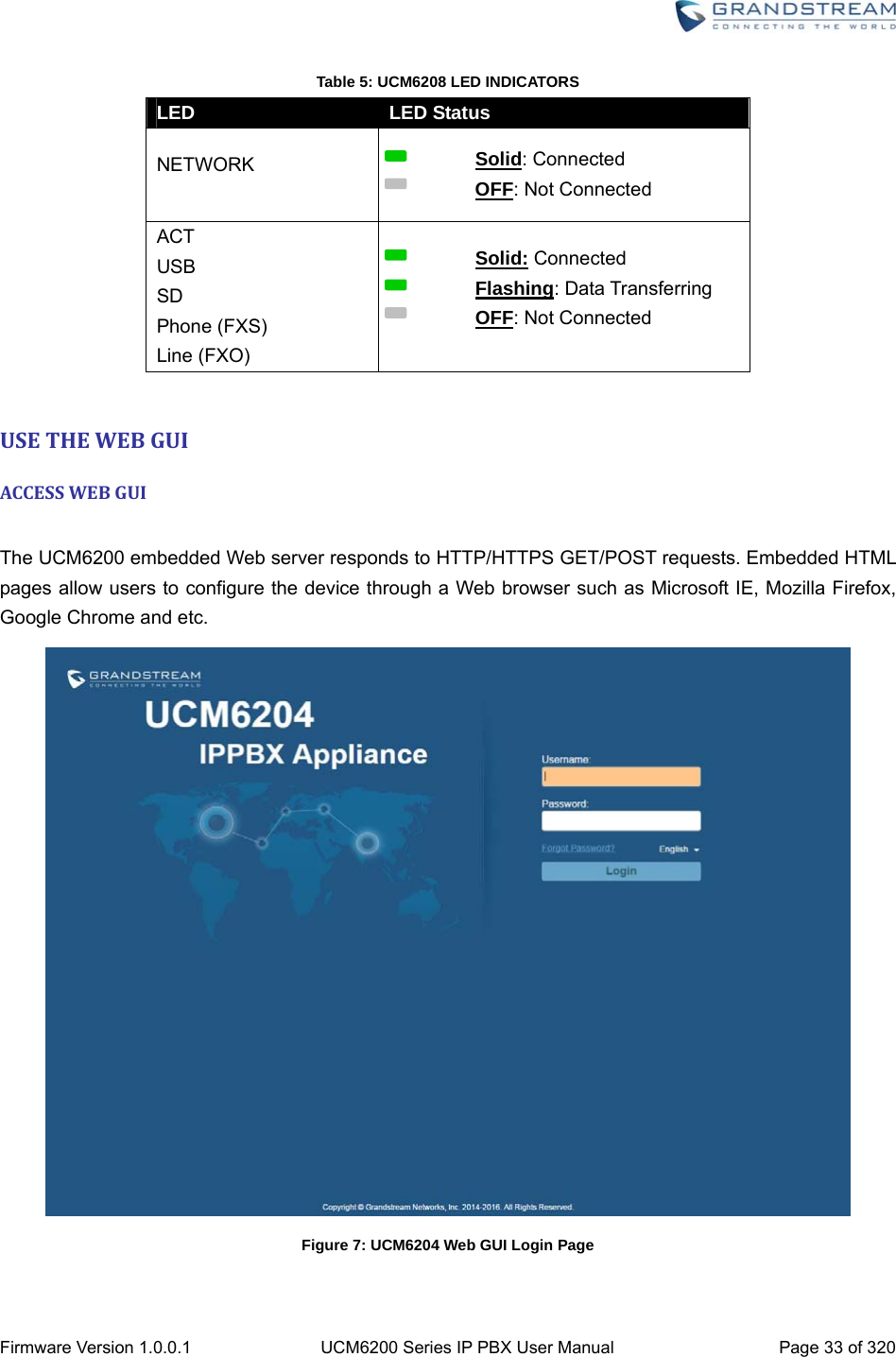
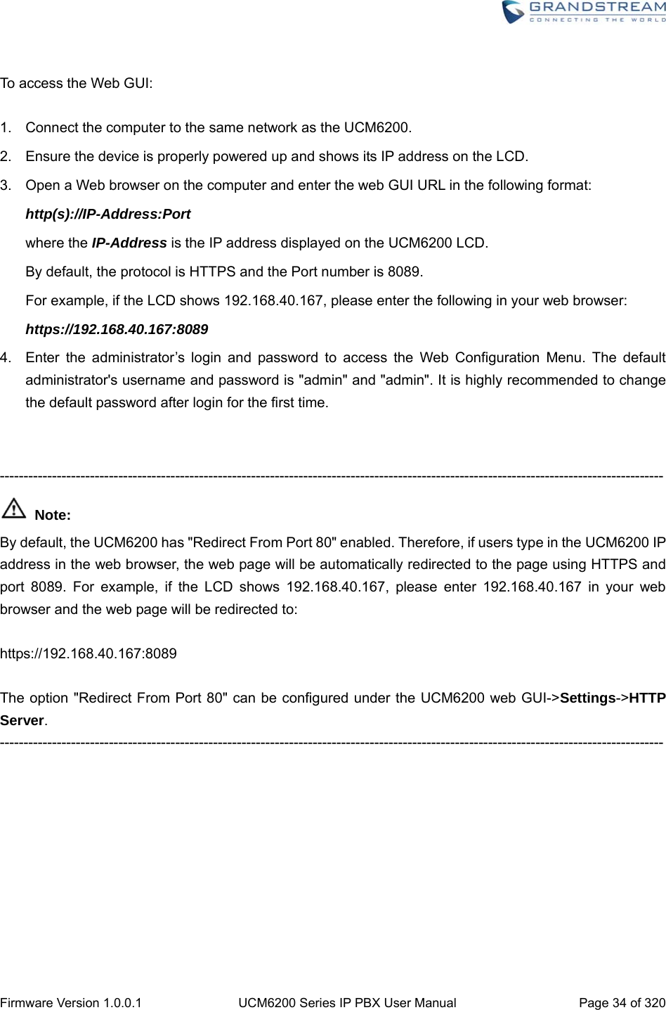
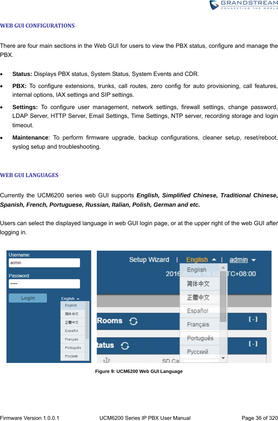
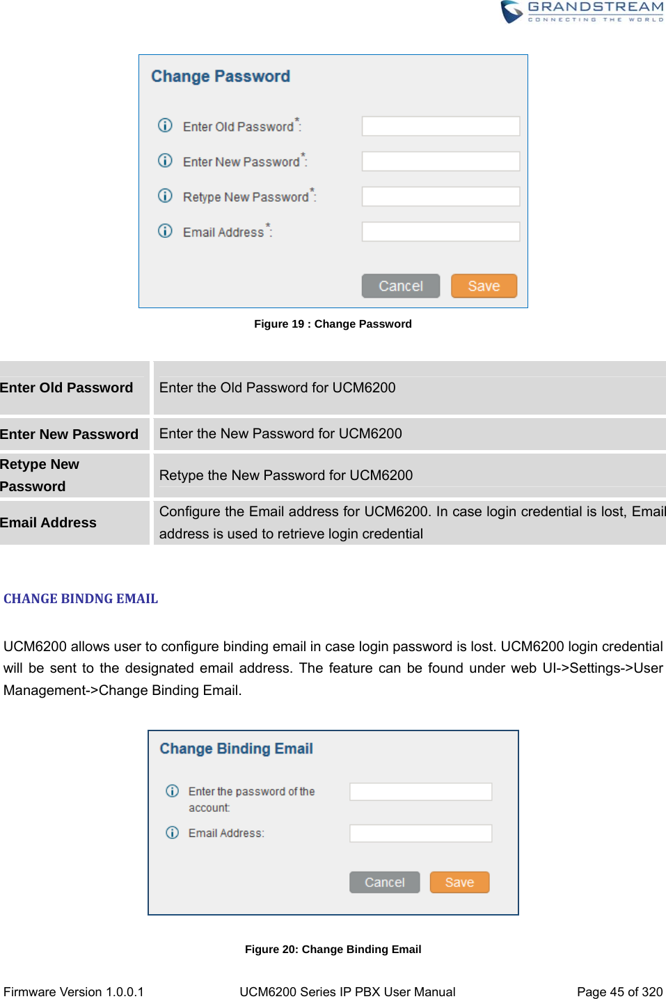
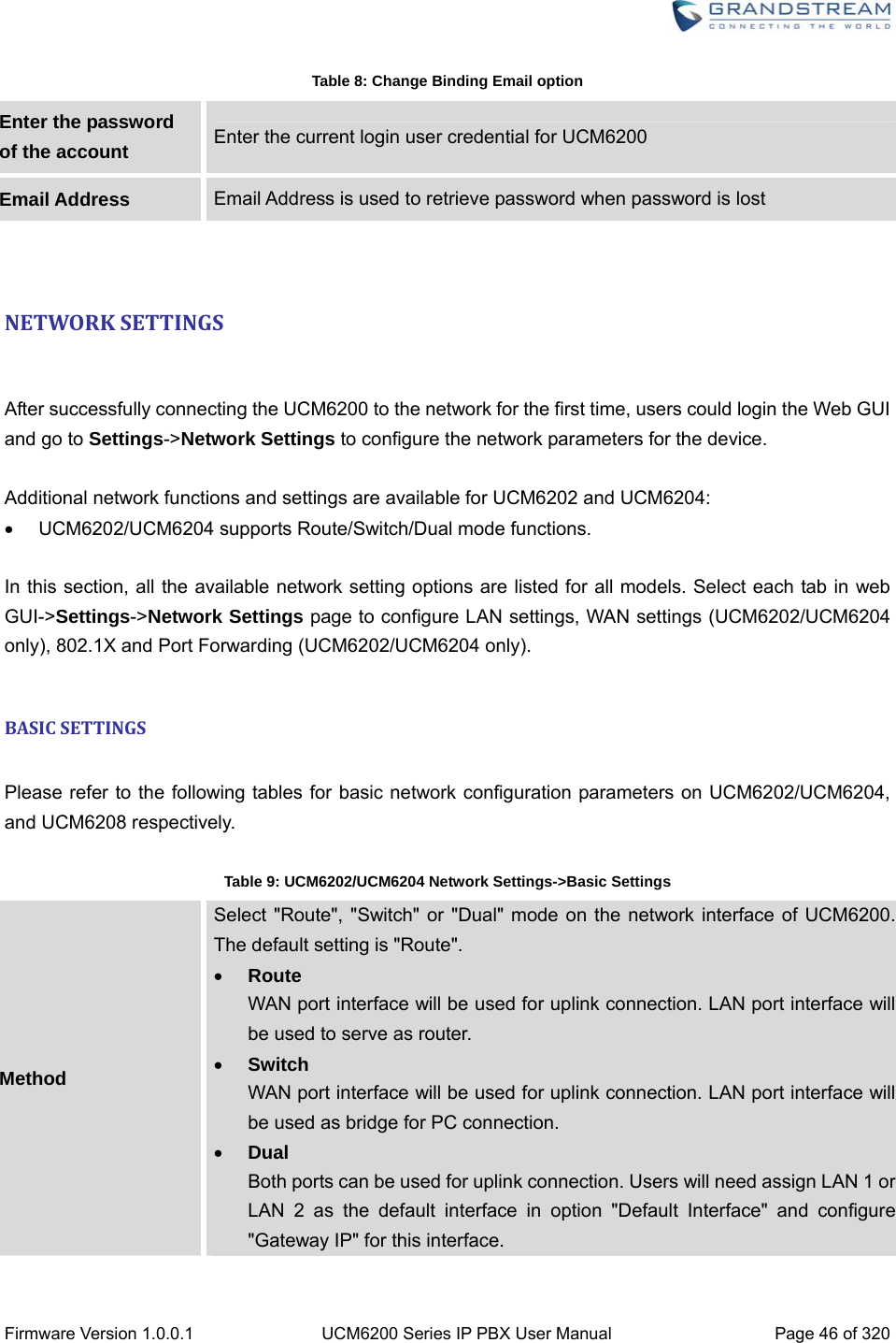
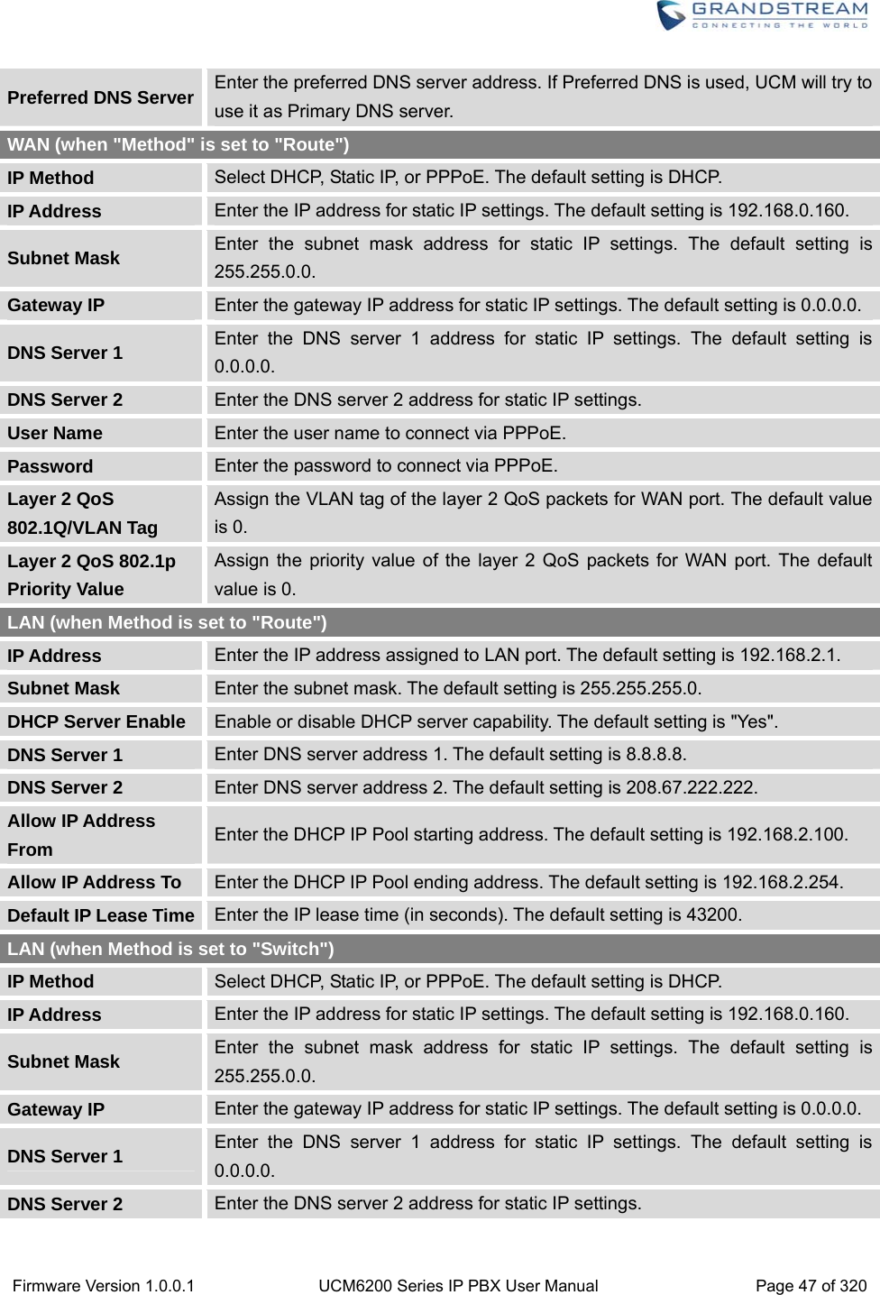
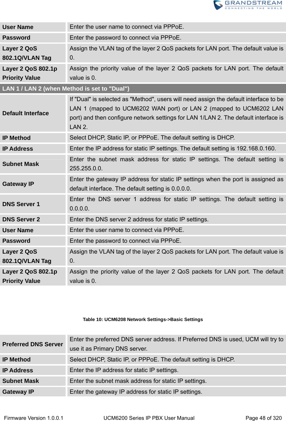
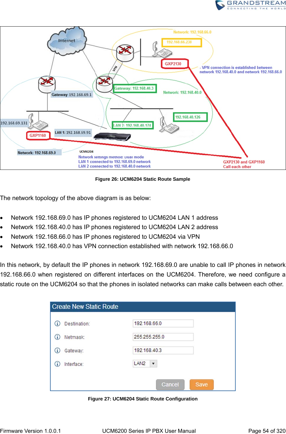
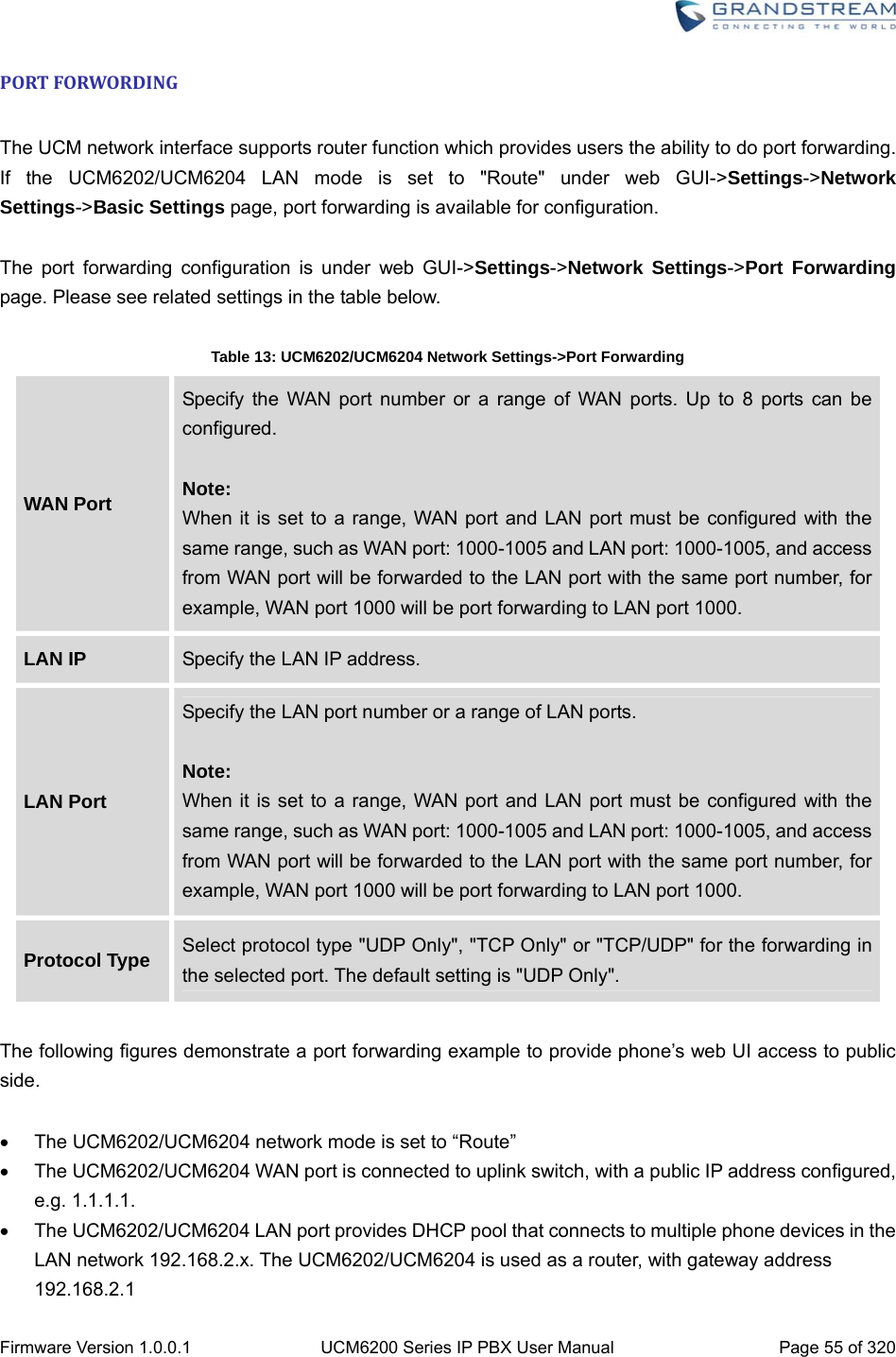
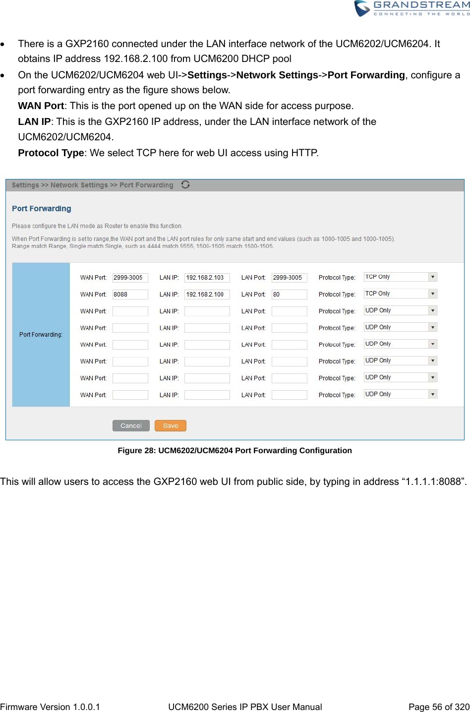
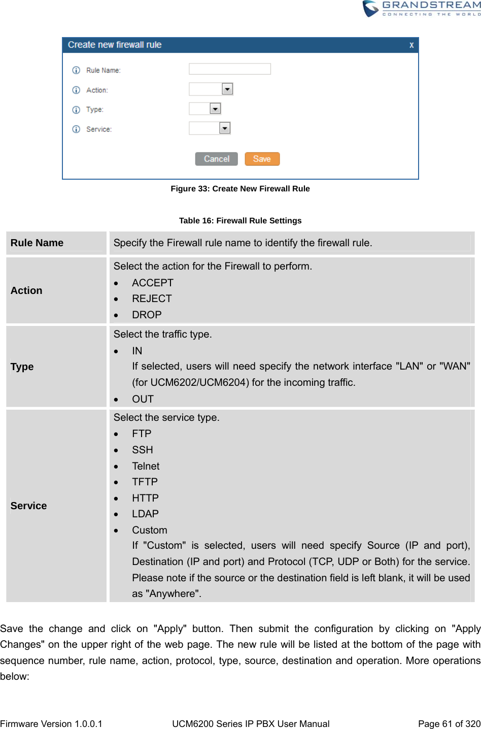
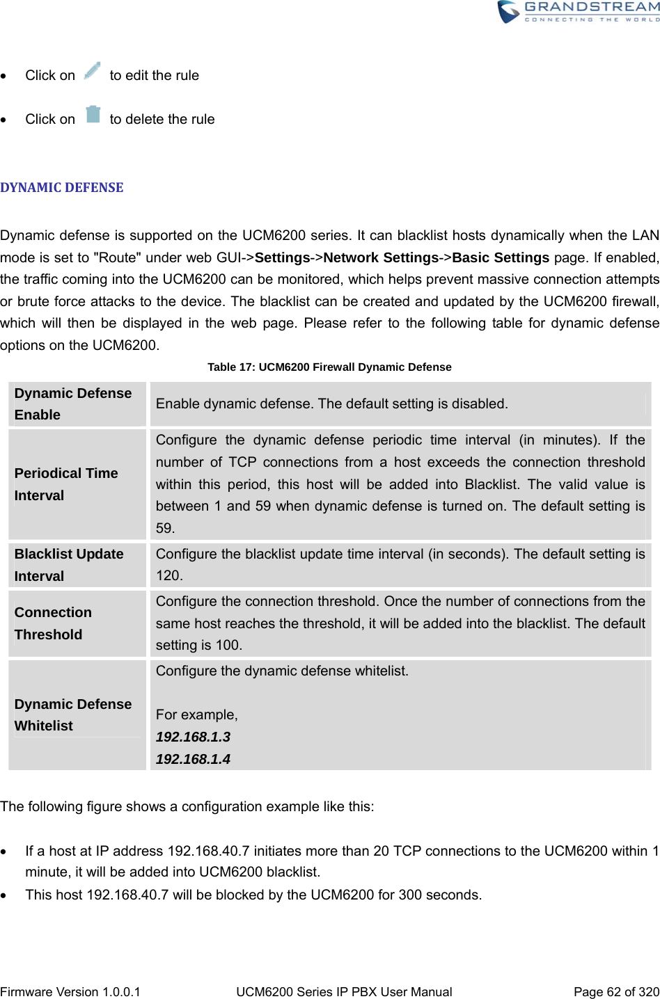
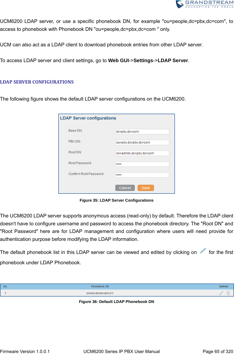
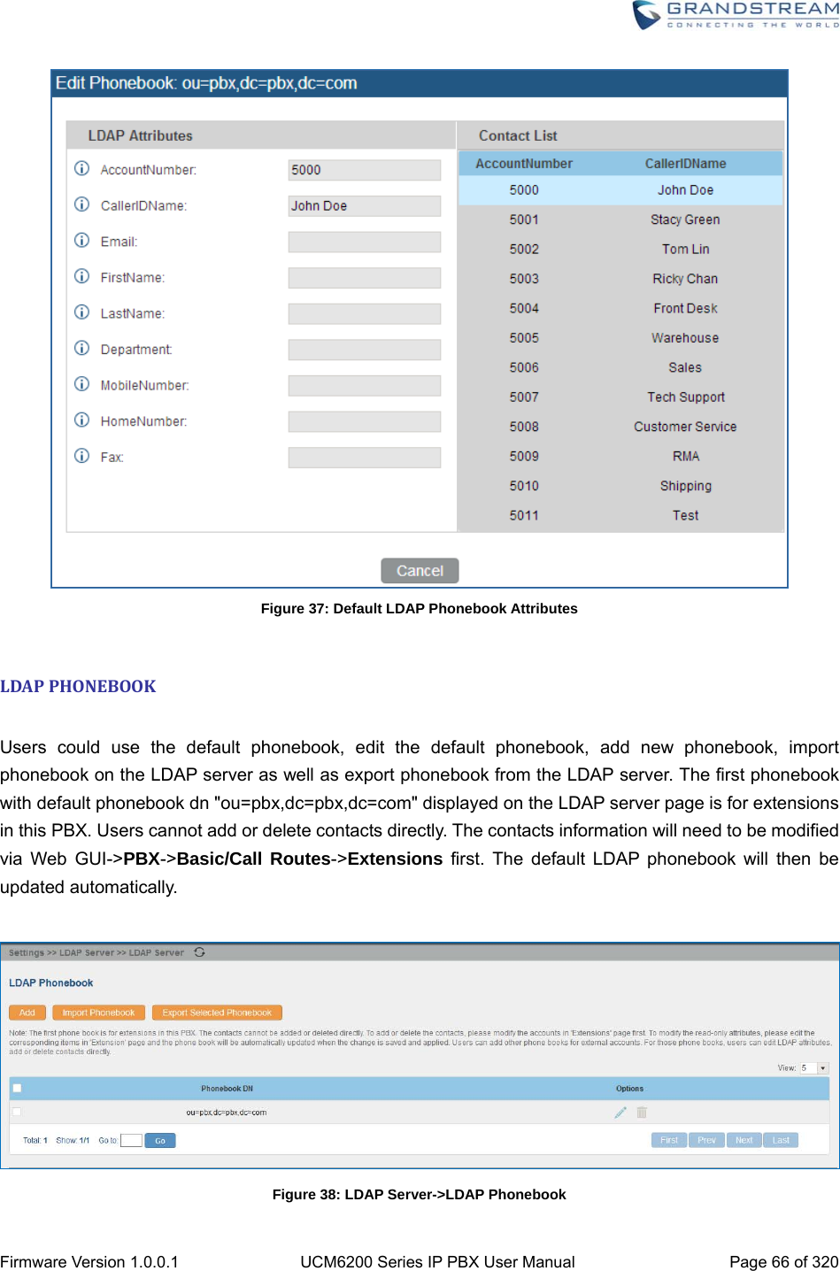
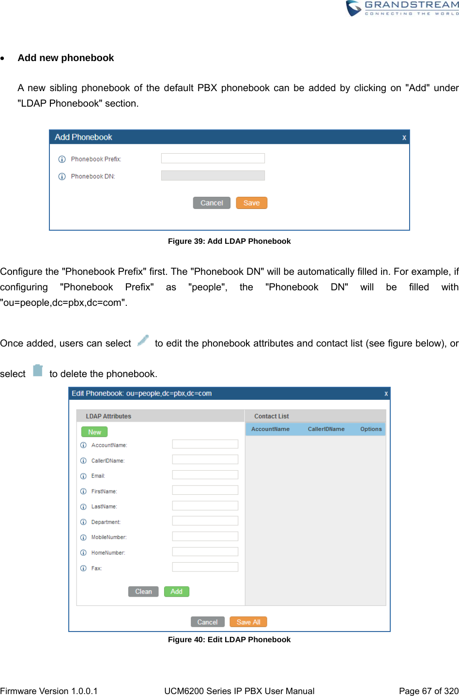
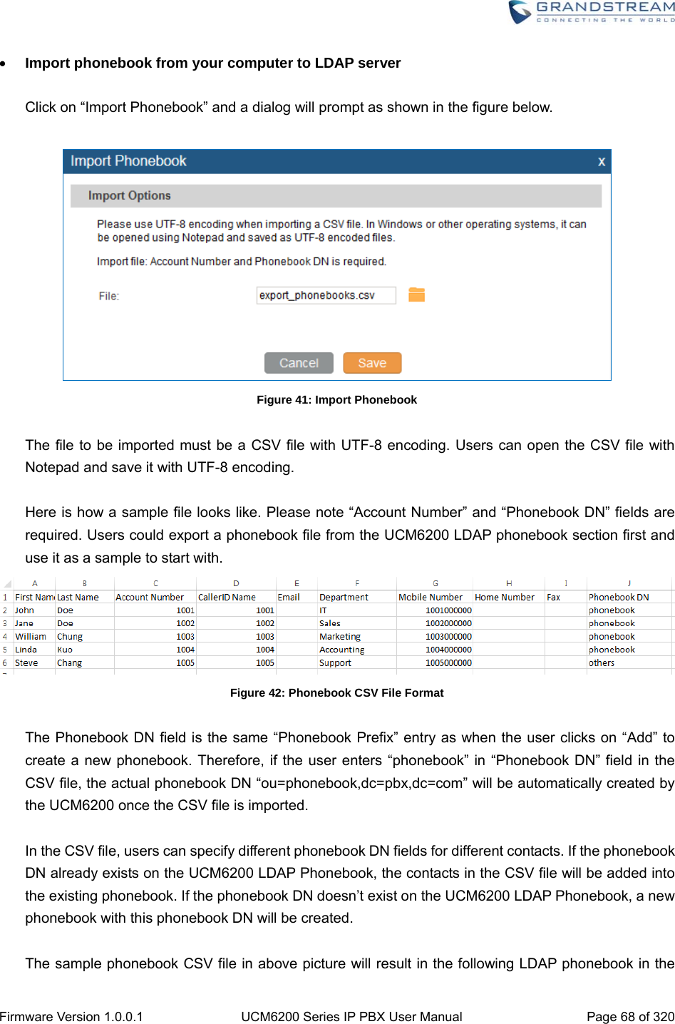
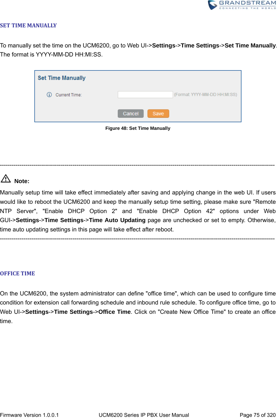
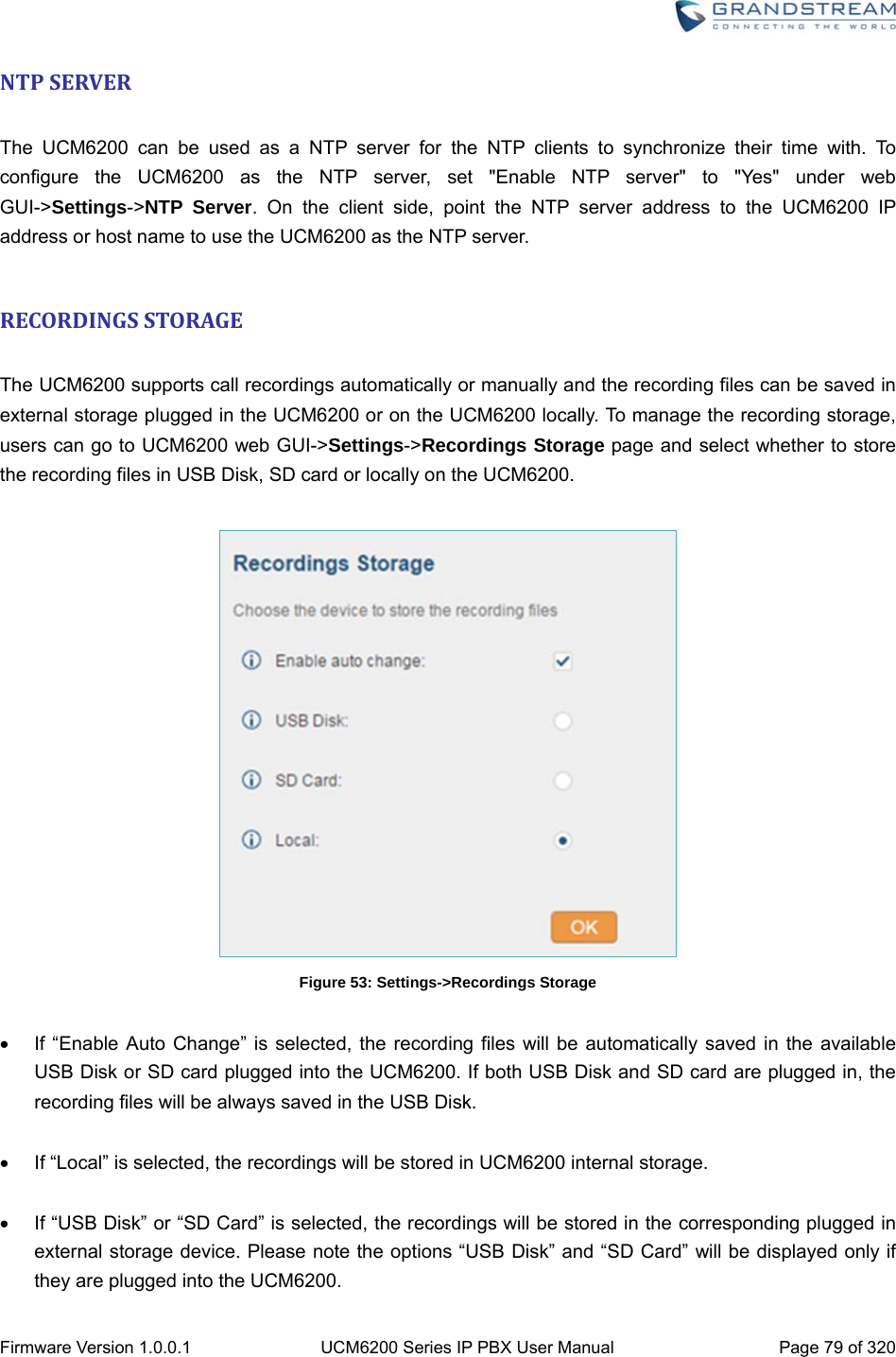
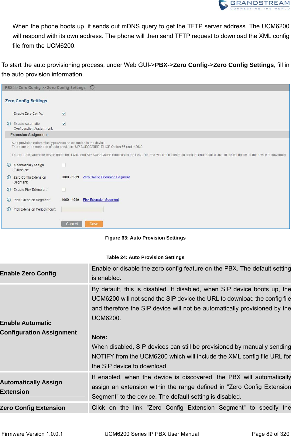
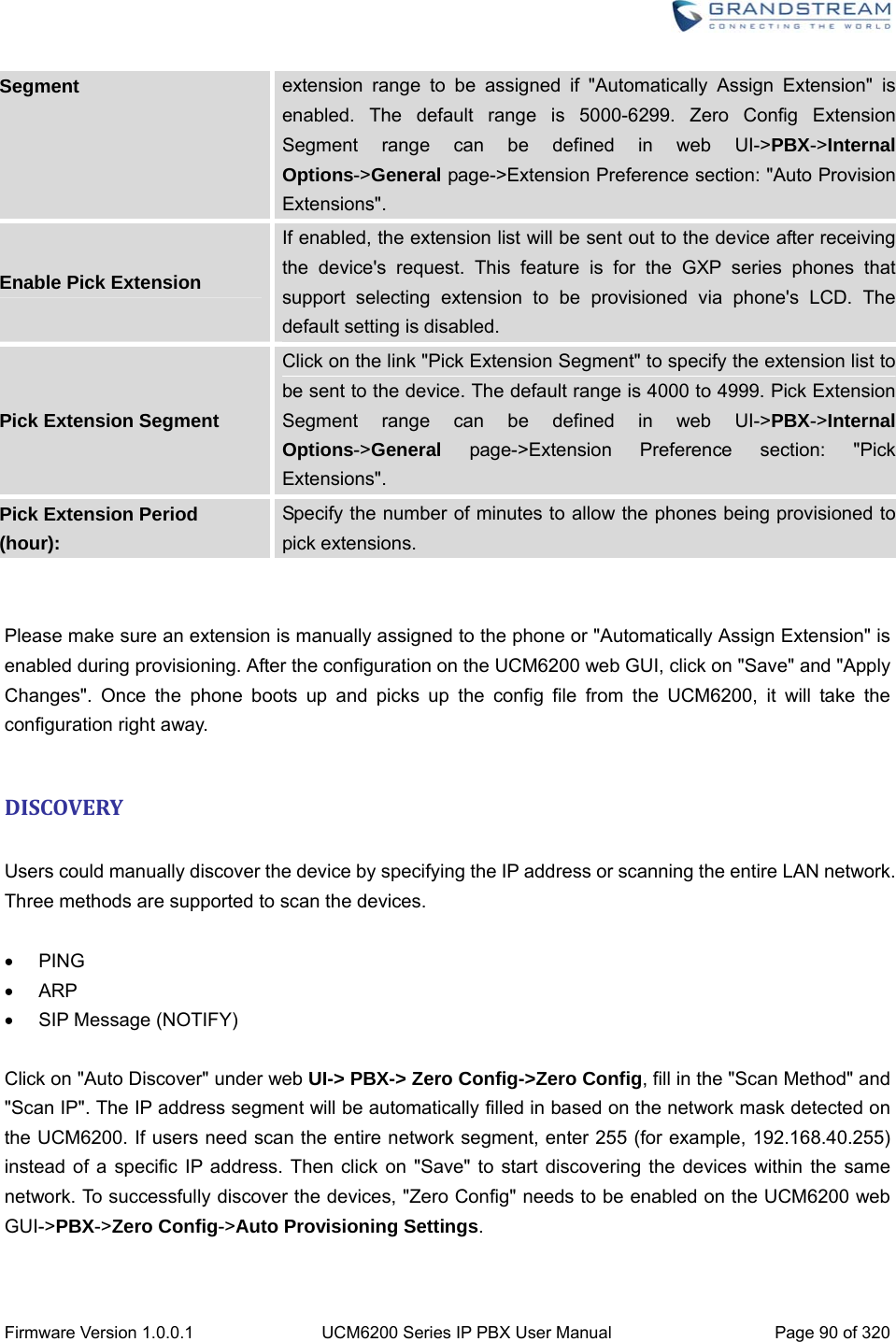
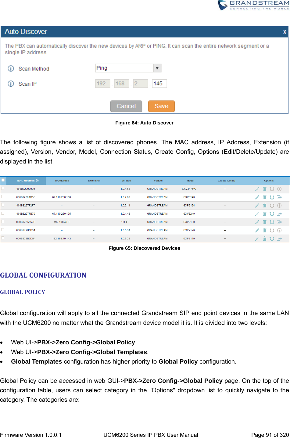
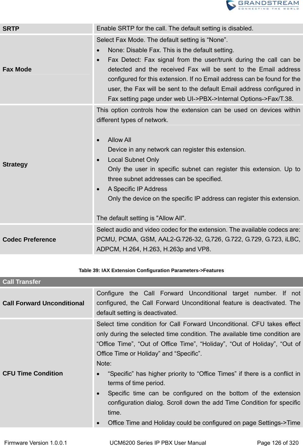
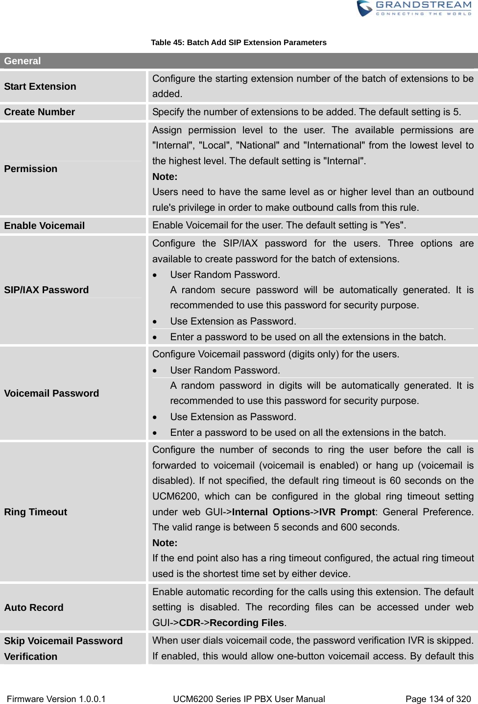
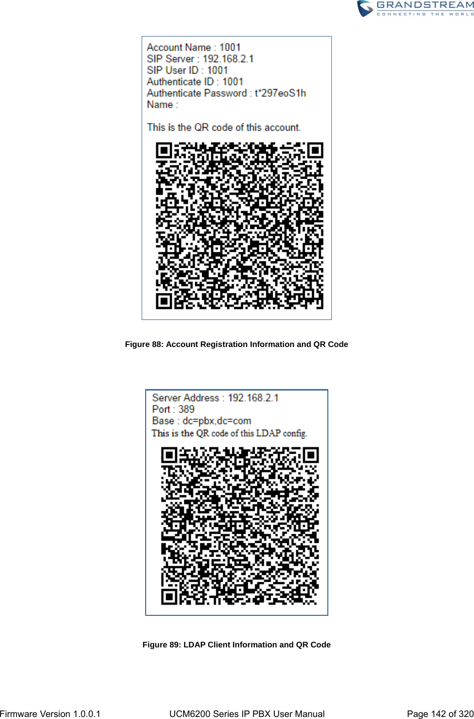
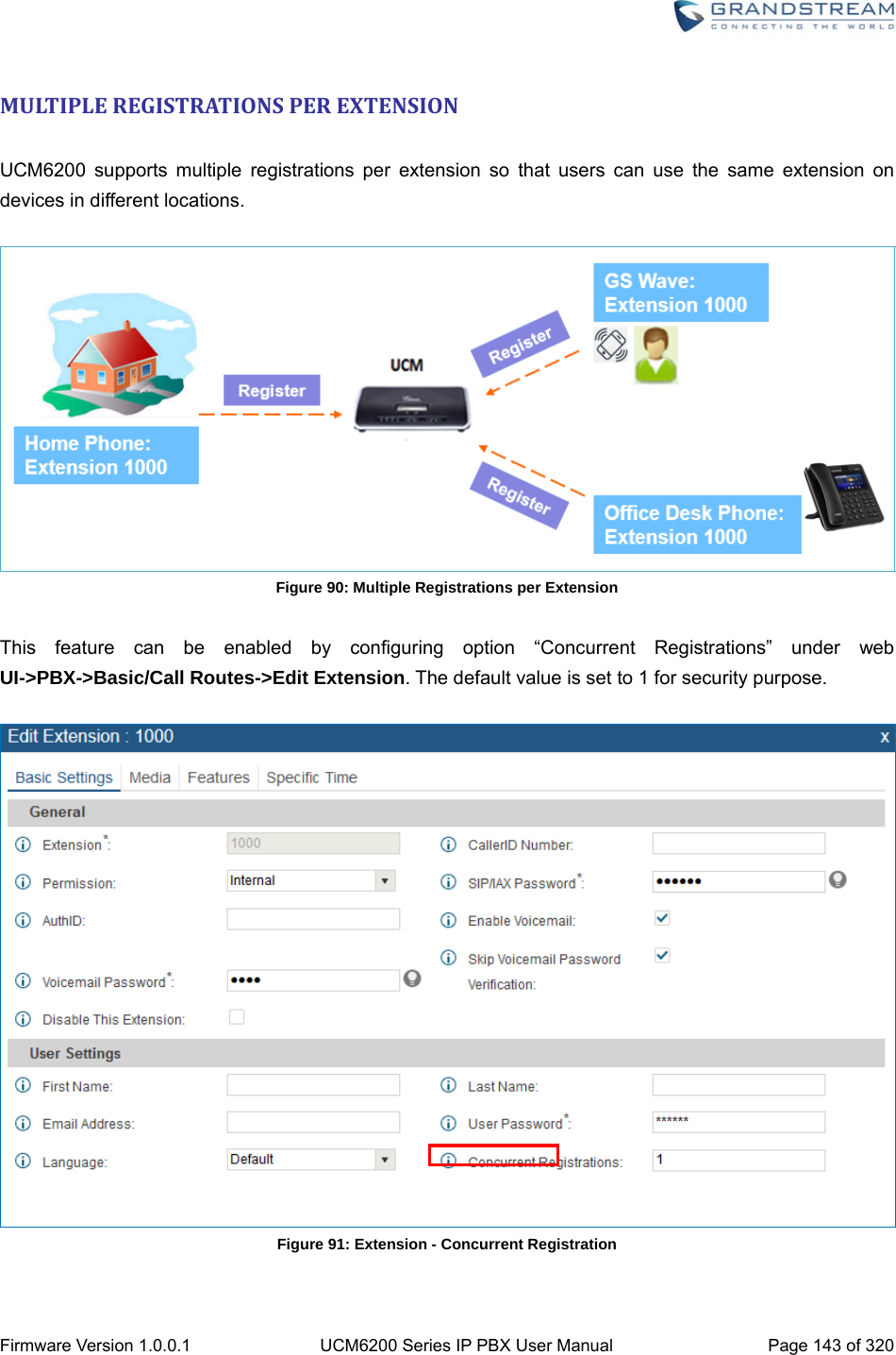
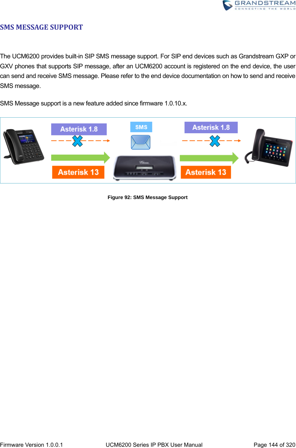
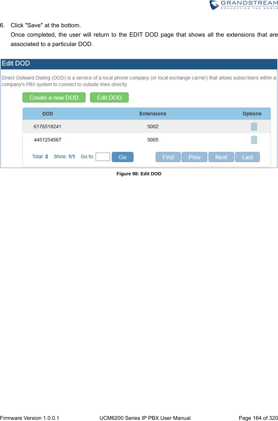
![Firmware Version 1.0.0.1 UCM6200 Series IP PBX User Manual Page 30 of 320 GETTINGSTARTED The UCM6200 series provides LCD interface, LED indication and web GUI configuration interface. The LCD displays hardware, software and network information. Users could also navigate in the LCD menu for device information and basic network configuration. The LED indication at the front of the device provides interface connection and activity status. The web GUI gives users access to all the configurations and options for UCM6200 series setup. This section provides step-by-step instructions on how to use the LCD menu, LED indicators and Web GUI of the UCM6200 series. Once the basic settings are done, users could start making calls from UCM6200 extension registered on a SIP phone as described at the end of this section. USETHELCDMENU Default LCD Display When the device is powered up, the LCD will show device model (e.g., UCM6204), hardware version (e.g., V1.0A) and IP address. Press "Down" button and the system time will be displayed as well. Menu Access Press "OK" button to start browsing menu options. Please see menu options in [Table 3: LCD Menu Options]. Menu Navigation Press the "Down" arrow key to browser different menu options. Press the "OK" button to select an entry. Exit If "Back" option is available in the menu, select it to go back to the previous menu. For "Device Info" "Network Info" and "Web Info" which do not have "Back" option, simply press the "OK" button to go back to the previous menu. Also, the LCD will display default idle screen after staying in menu option for 15 seconds. LCD Backlight The LCD backlight will be on upon key pressing. The backlight will go off after the LCD stays in idle for 30 seconds. ](https://usermanual.wiki/Grandstream-Networks/UCM6208.Users-Manual-Part-One/User-Guide-3044584-Page-31.png)
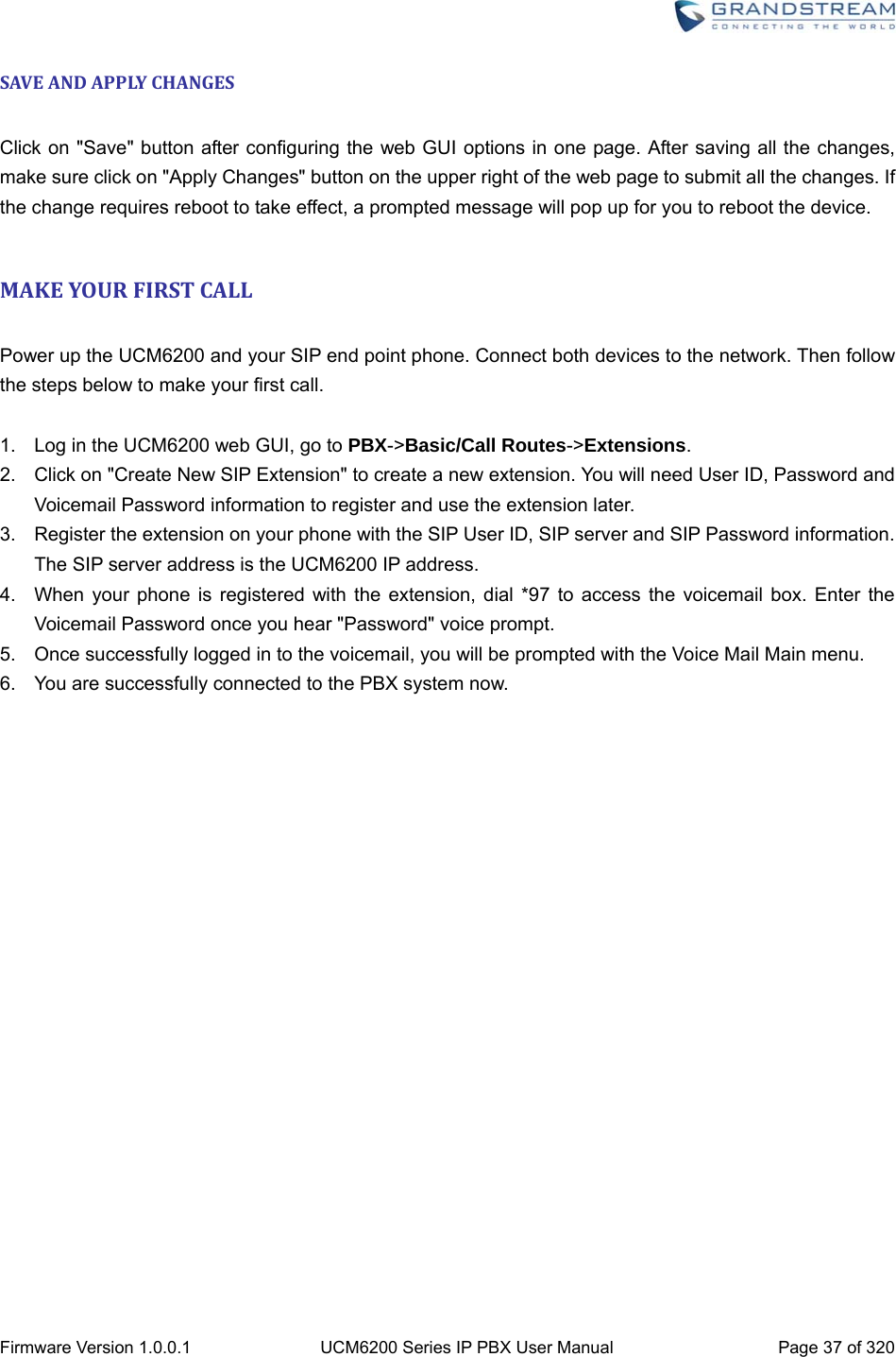
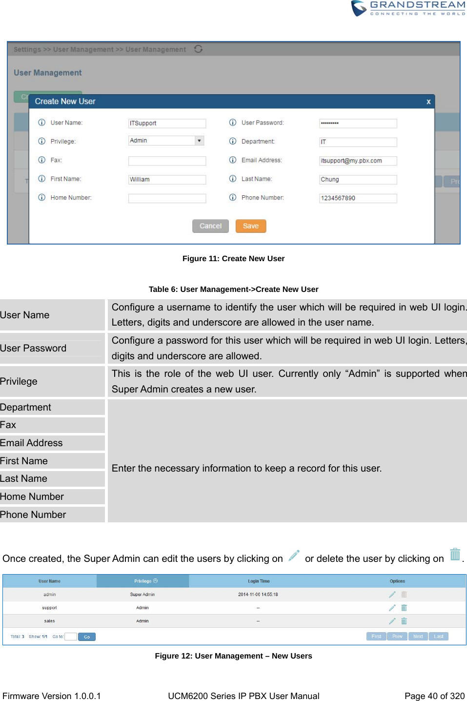
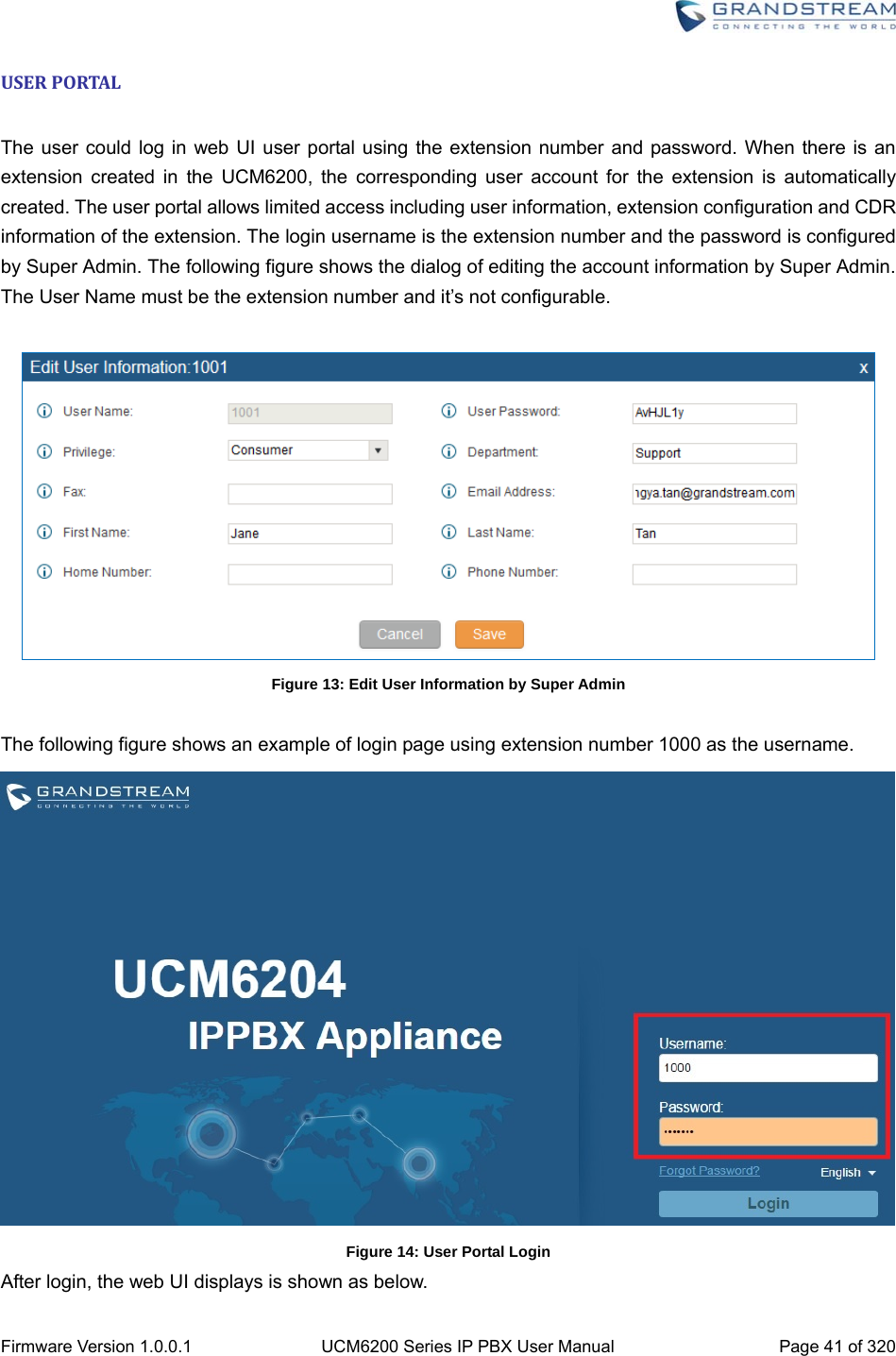
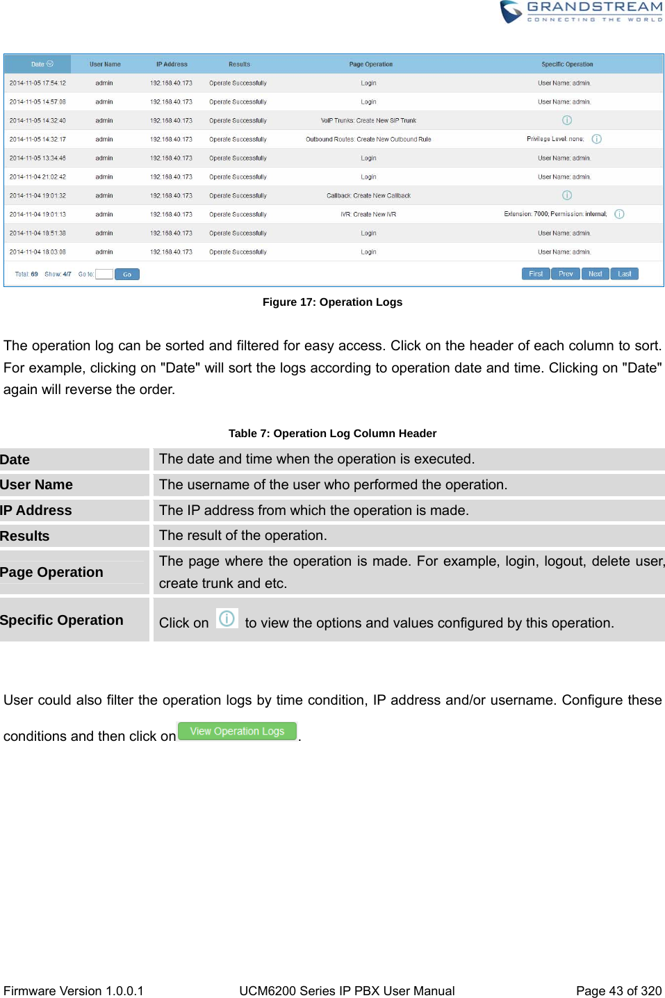
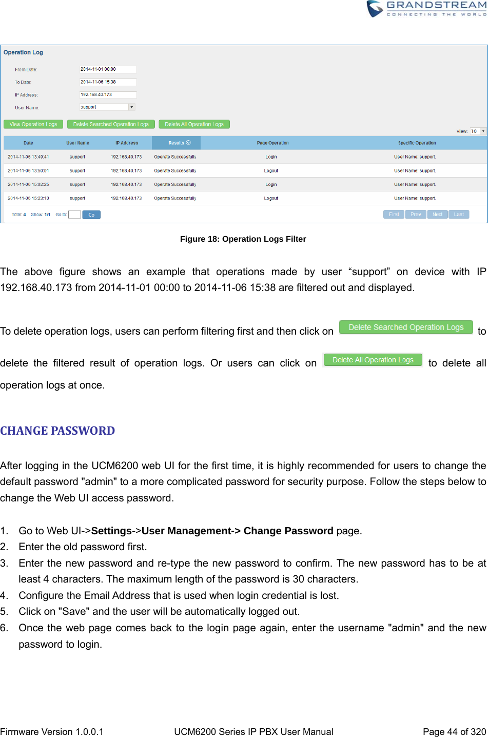
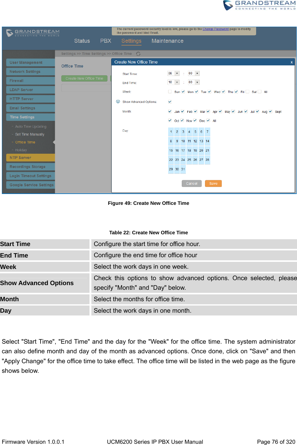
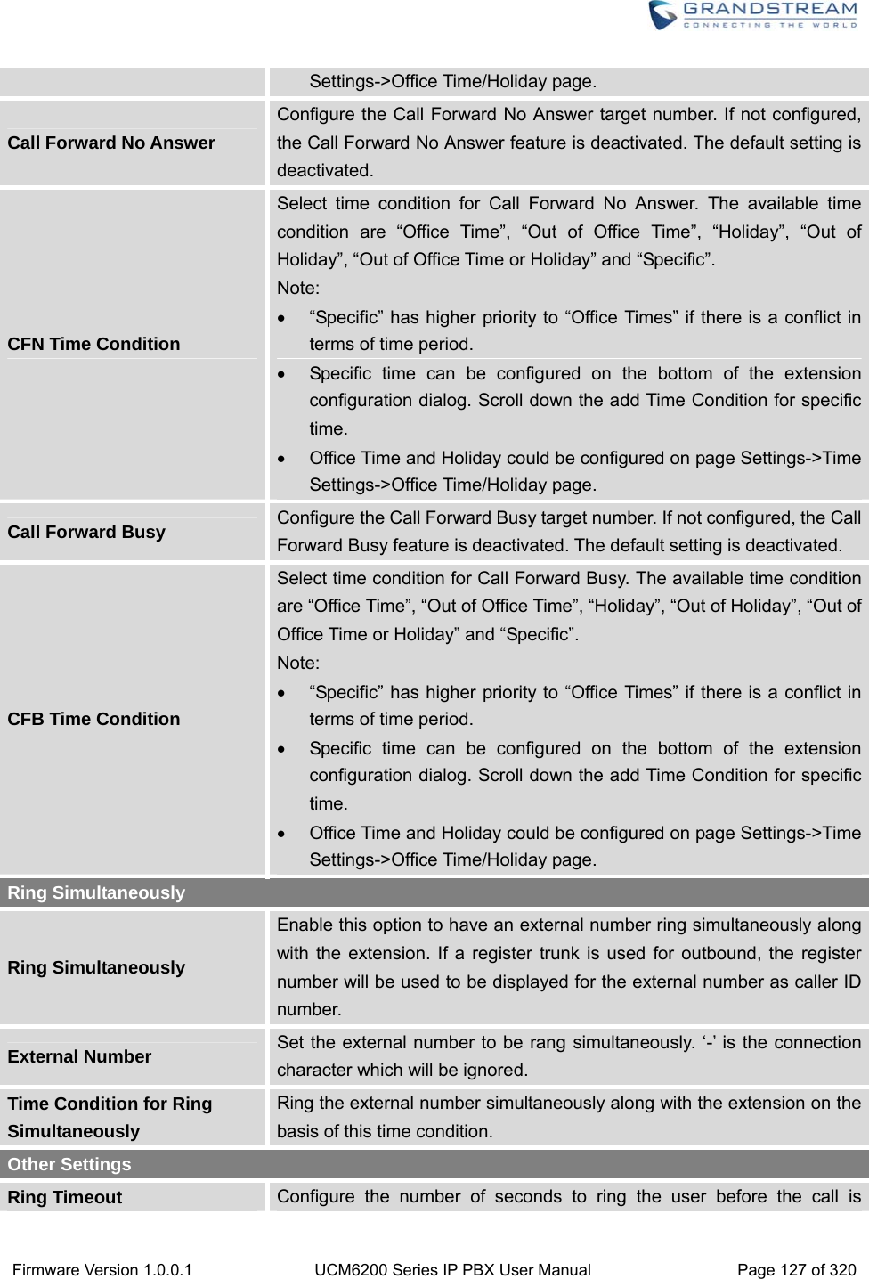
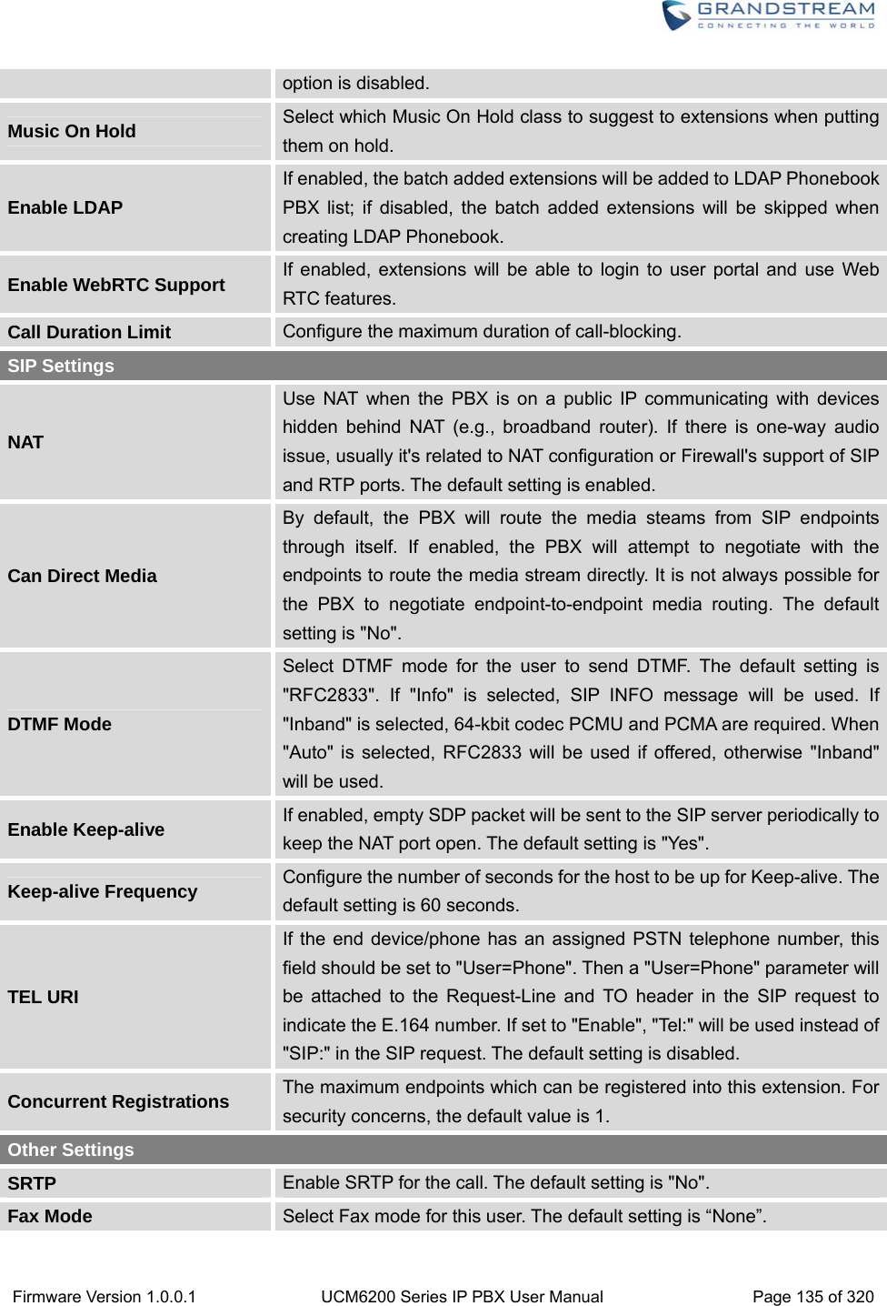
![Firmware Version 1.0.0.1 UCM6200 Series IP PBX User Manual Page 42 of 320 Figure 15: User Portal Layout For the configuration parameter information in each page, please refer to [Table 6: User Management->Create New User] for options in User Portal->Basic Information->User Information page; please refer to [EXTENSIONS] for options in User Portal->Basic Information->Extension page; please refer to [CDR] for User Portal->Basic Information->CDR page. CONCURRENTMULTI‐USERLOGIN When there are multiple web UI users created, concurrent multi-user login is supported on the UCM6200. Multiple users could edit options and have configurations take effect simultaneously. However, if different users are editing the same option or making the same operation (by clicking on “Apply Changes”), a prompt will pop up as shown in the following figure. Figure 16: Multiple User Operation Error Prompt OPERATIONLOG Super Admin has the authority to view operation logs on UCM6200 web GUI->Settings->User Management->Operation Log page. Operation logs list operations done by all the web UI users, for example, web UI login, creating trunk, creating outbound rule and etc. There are 6 columns to record the operation details “Date”, “User Name”, “IP Address”, “Results”, “Page Operation” and “Specific Operation”.](https://usermanual.wiki/Grandstream-Networks/UCM6208.Users-Manual-Part-One/User-Guide-3044584-Page-43.png)
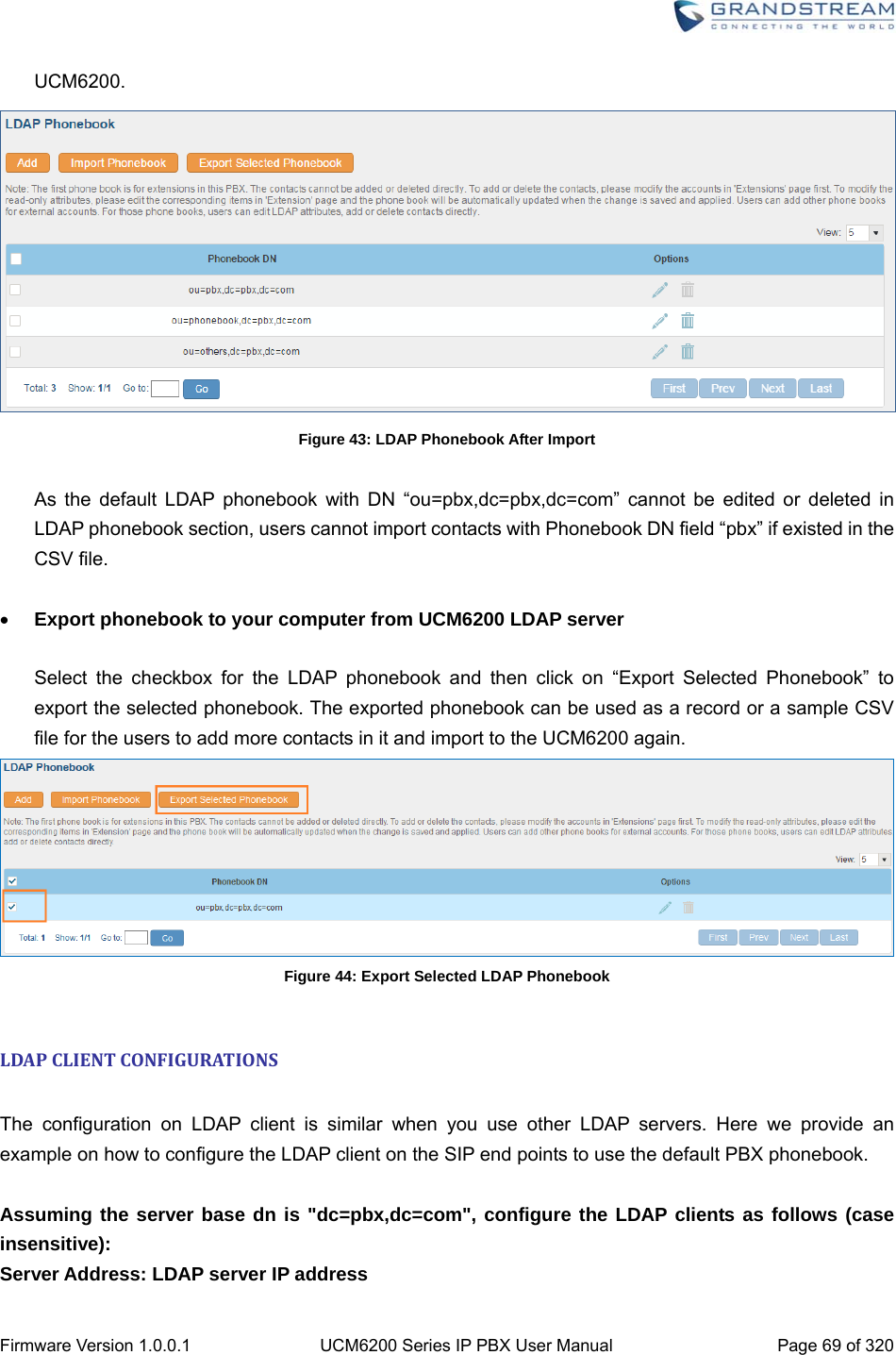
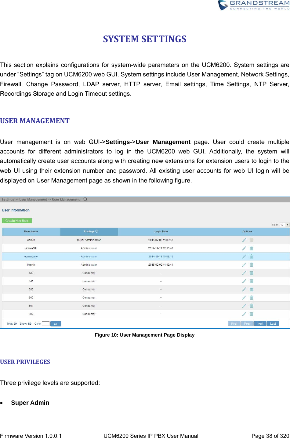
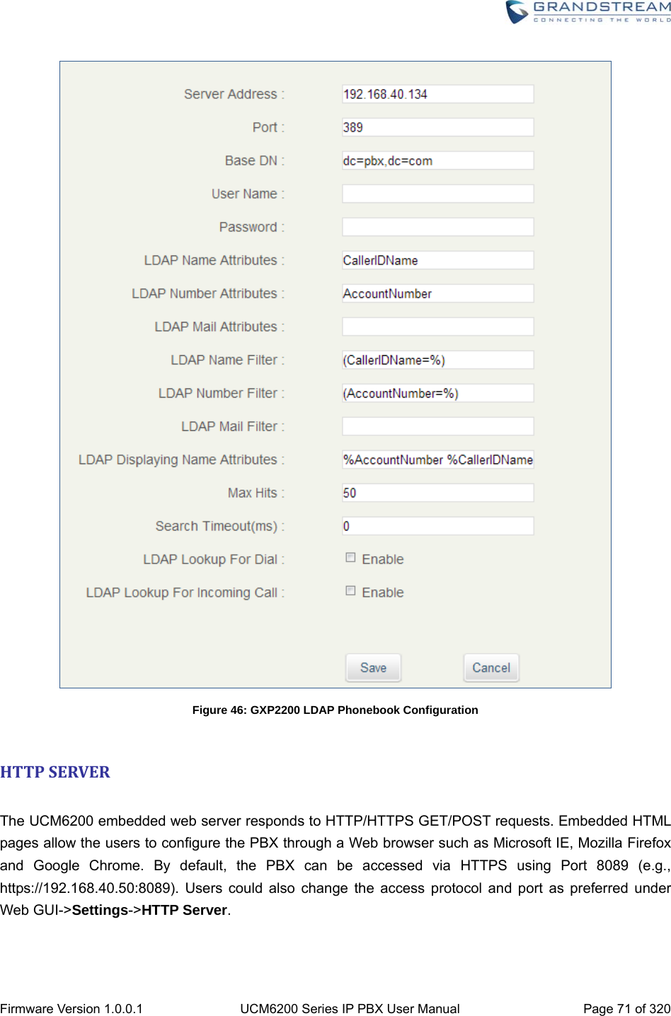
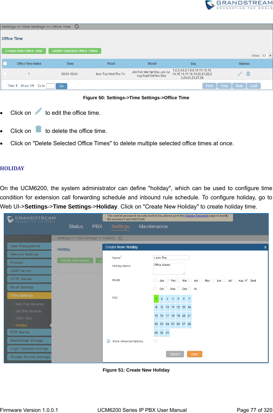
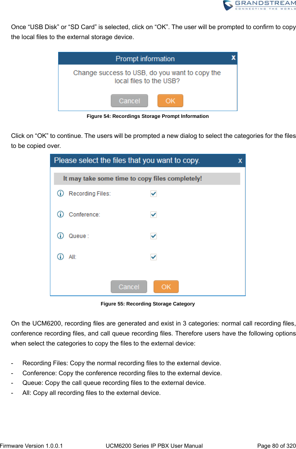
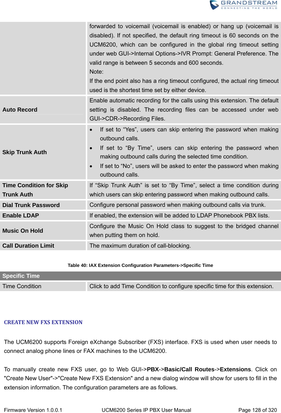
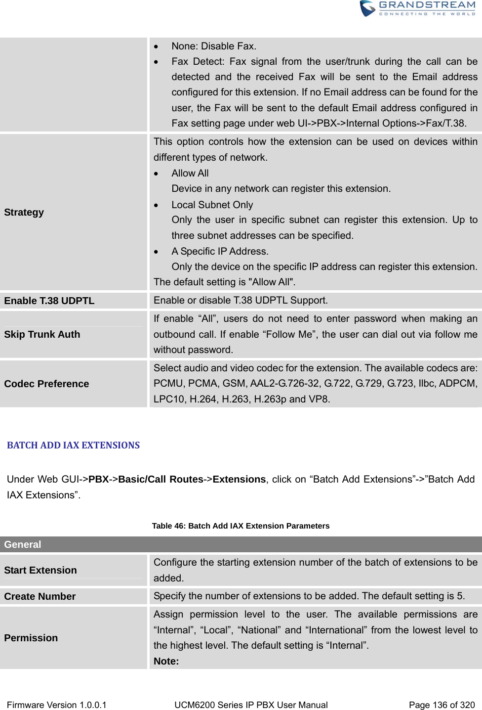
![Firmware Version 1.0.0.1 UCM6200 Series IP PBX User Manual Page 70 of 320 Base DN: dc=pbx,dc=com User Name: cn= “LDAP server login name”, dc=pbx, dc=com [matching LDAP server format] Password: “LDAP server login password” Filter: (|(CallerIDName=%)(AccountNumber=%)) Port: 389 The following figure gives a sample configurations for UCM6200 acting as a LDAP client. Figure 45: LDAP Client Configurations To configure Grandstream IP phones as the LDAP client, please refer to the following example: Server Address: The IP address or domain name of the UCM6200 Base DN: dc=pbx,dc=com User Name: Please leave this field empty Password: Please leave this field empty LDAP Name Attribute: CallerIDName Email Department FirstName LastName LDAP Number Attribute: AccountNumber MobileNumber HomeNumber Fax LDAP Number Filter: (AccountNumber=%) LDAP Name Filter: (CallerIDName=%) LDAP Display Name: AccountNumber CallerIDName LDAP Version: If existed, please select LDAP Version 3 Port: 389 The following figure shows the configuration information on a Grandstream GXP2200 to successfully use the LDAP server as configured in Figure 35: LDAP Server Configurations.](https://usermanual.wiki/Grandstream-Networks/UCM6208.Users-Manual-Part-One/User-Guide-3044584-Page-71.png)
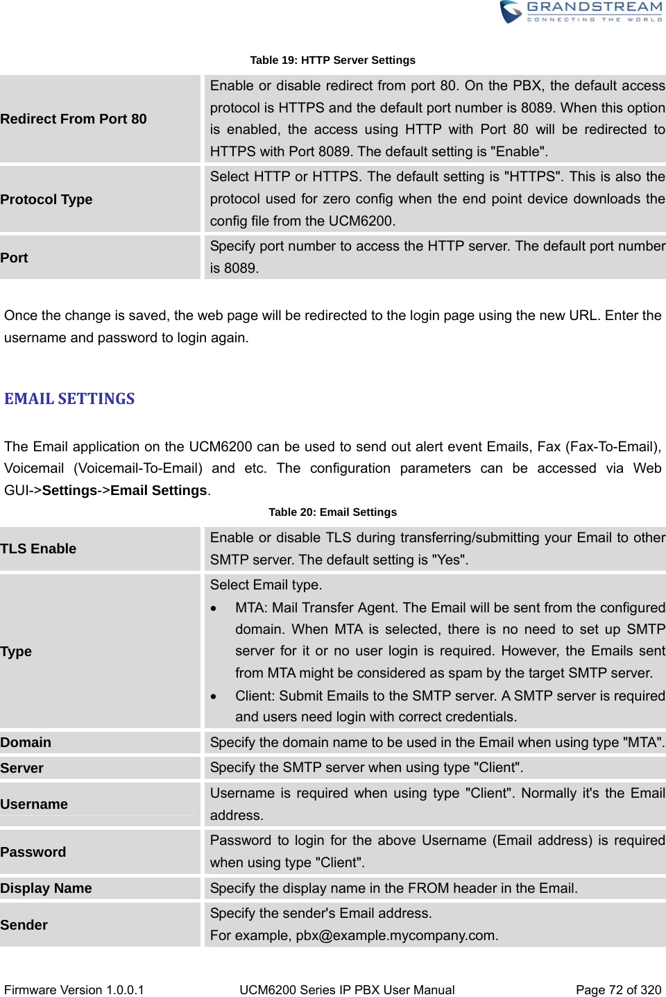
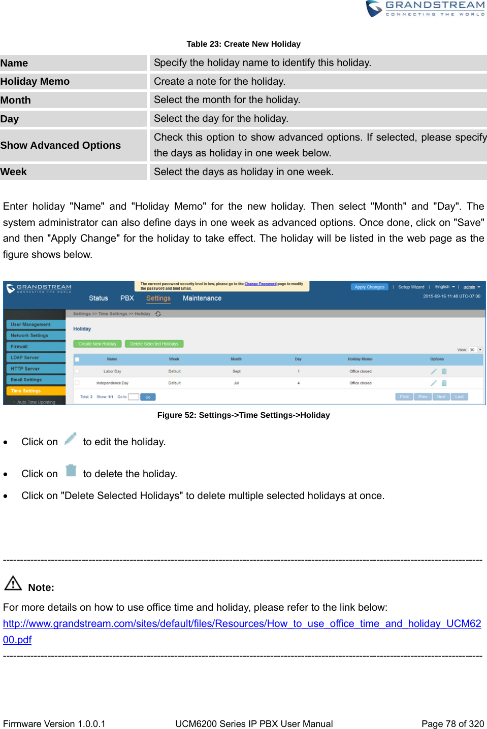
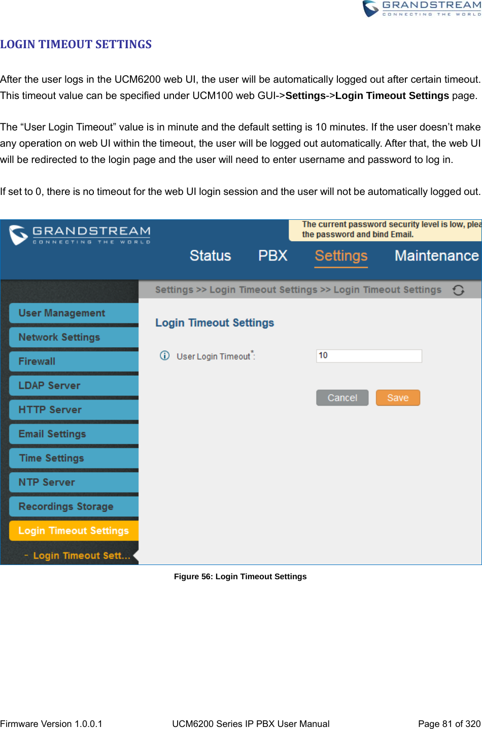
![Firmware Version 1.0.0.1 UCM6200 Series IP PBX User Manual Page 74 of 320 Table 21: Time Auto Updating Remote NTP Server Specify the URL or IP address of the NTP server for the UCM6200 to synchronize the date and time. The default NTP server is ntp.ipvideotalk.com. Enable DHCP Option 2 If set to "Yes", the UCM6200 is allowed to get provisioned for Time Zone from DHCP Option 2 in the local server automatically. The default setting is "Yes". Enable DHCP Option 42 If set to "Yes", the UCM6200 is allowed to get provisioned for NTP Server from DHCP Option 42 in the local server automatically. This will override the manually configured NTP Server. The default setting is "Yes". Time Zone Select the proper time zone option so the UCM6200 can display correct time accordingly. If "Self-Defined Tome Zone" is selected, please specify the time zone parameters in "Self-Defined Time Zone" field as described in below option. Self-Defined Time Zone If "Self-Defined Time Zone" is selected in "Time Zone" option, users will need define their own time zone following the format below. The syntax is: std offset dst [offset], start [/time], end [/time] Default is set to: MTZ+6MDT+5,M4.1.0,M11.1.0 MTZ+6MDT+5 This indicates a time zone with 6 hours offset and 1 hour ahead for DST, which is U.S central time. If it is positive (+), the local time zone is west of the Prime Meridian (A.K.A: International or Greenwich Meridian); If it is negative (-), the local time zone is east. M4.1.0,M11.1.0 The 1st number indicates Month: 1,2,3.., 12 (for Jan, Feb, .., Dec). The 2nd number indicates the nth iteration of the weekday: (1st Sunday, 3rd Tuesday…). Normally 1, 2, 3, 4 are used. If 5 is used, it means the last iteration of the weekday. The 3rd number indicates weekday: 0,1,2,..,6 ( for Sun, Mon, Tues, ... ,Sat). Therefore, this example is the DST which starts from the First Sunday of April to the 1st Sunday of November.](https://usermanual.wiki/Grandstream-Networks/UCM6208.Users-Manual-Part-One/User-Guide-3044584-Page-75.png)
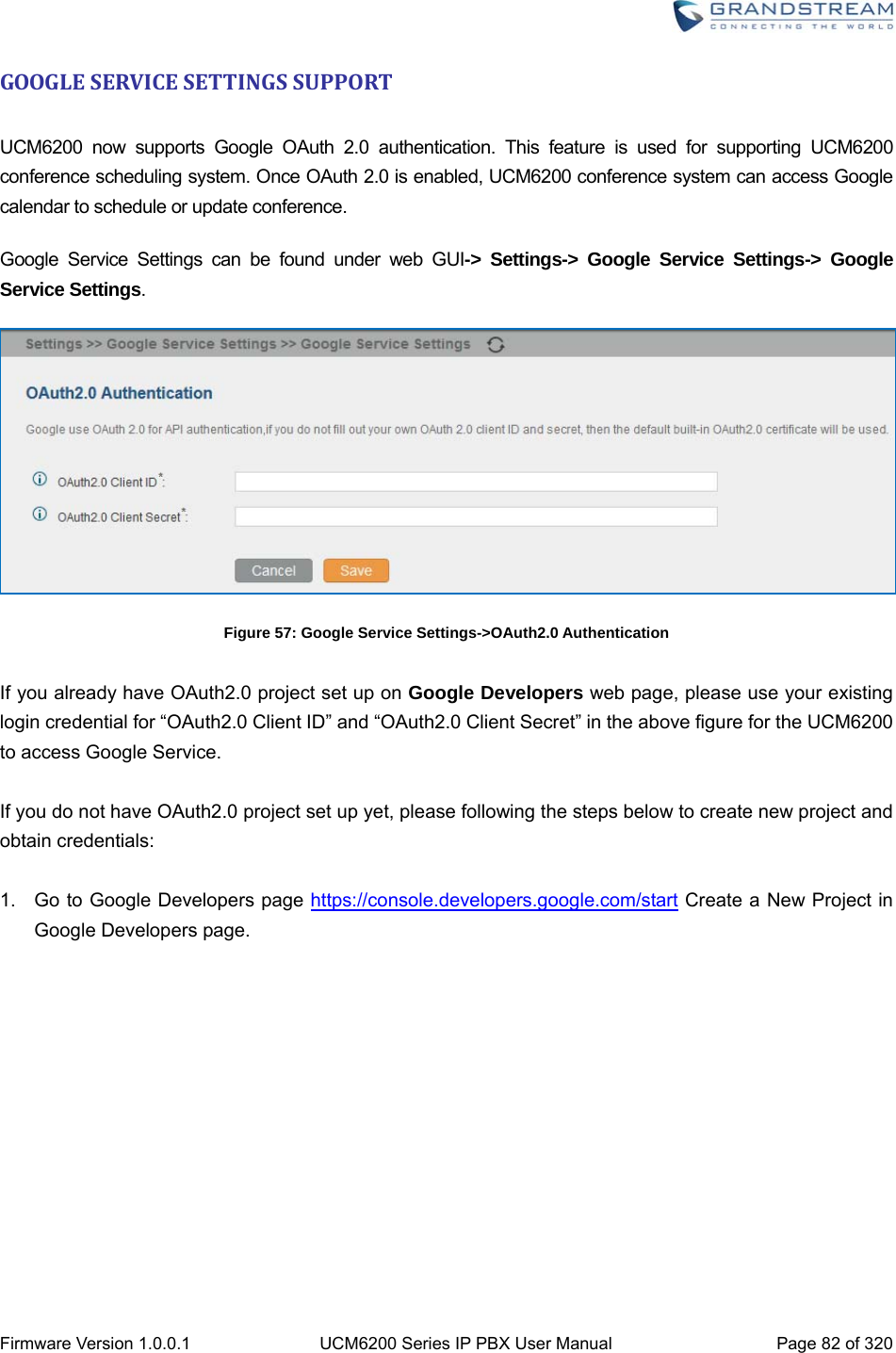
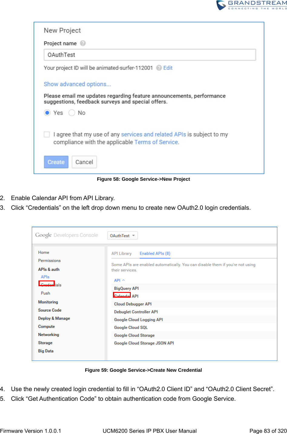
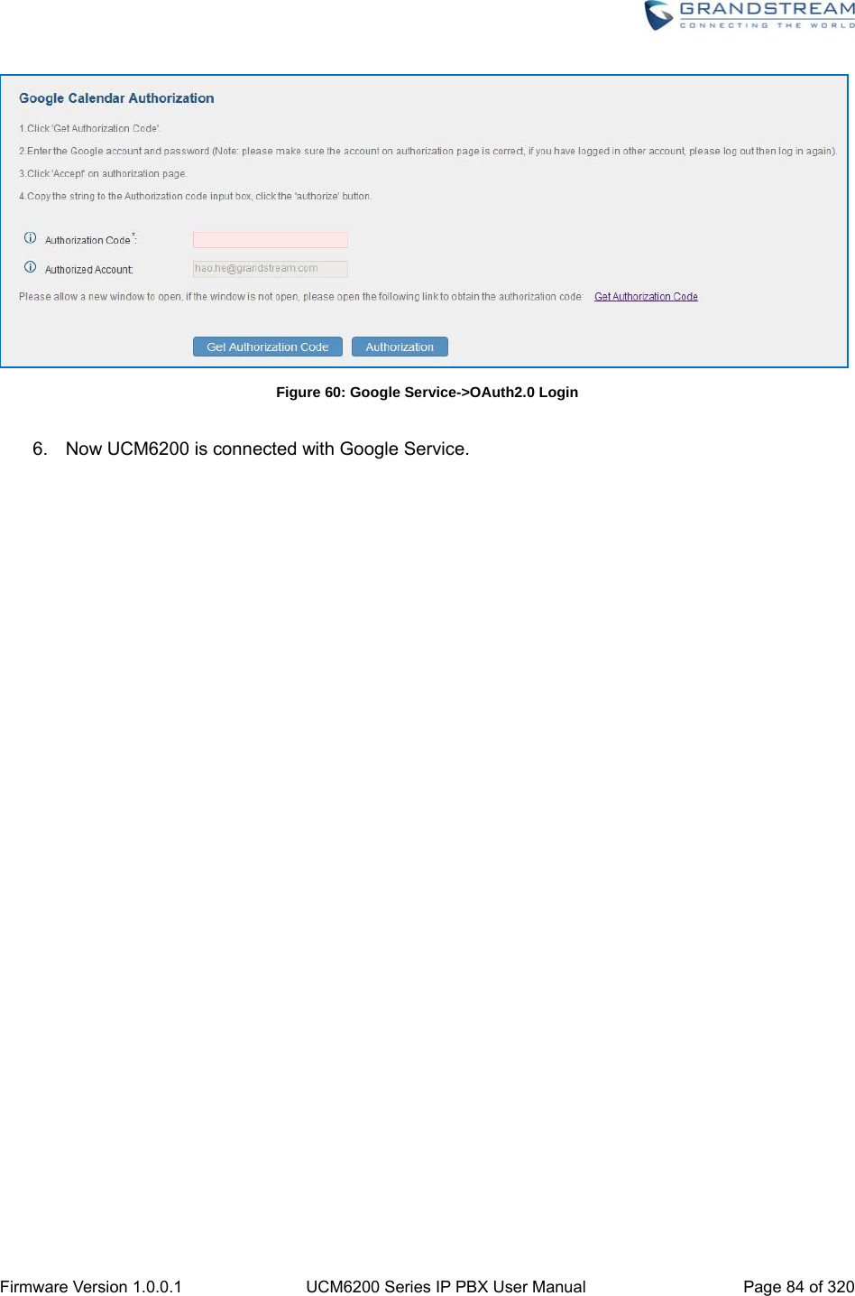

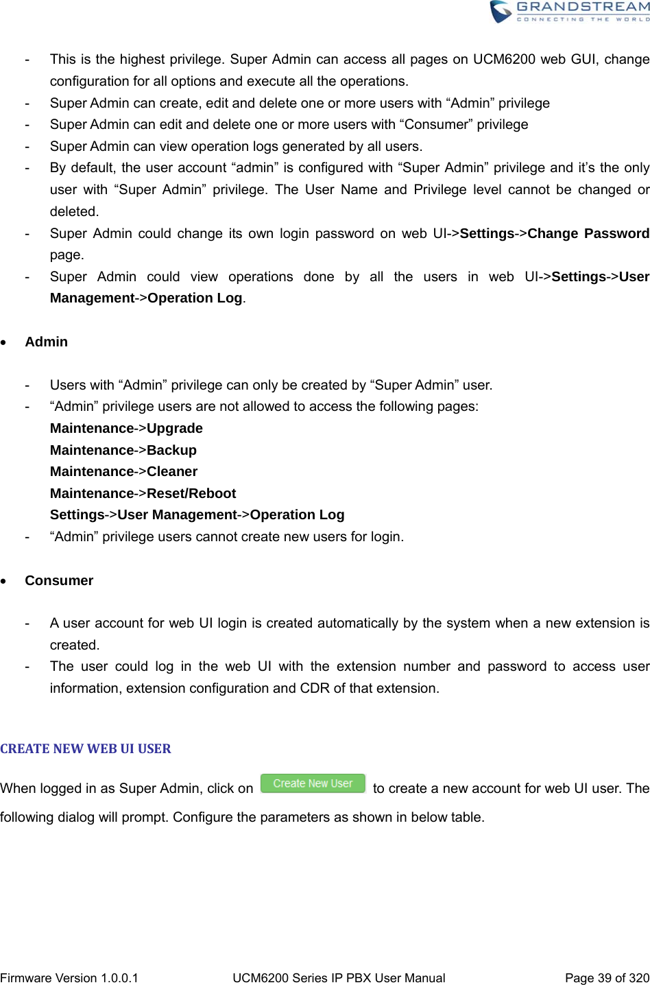
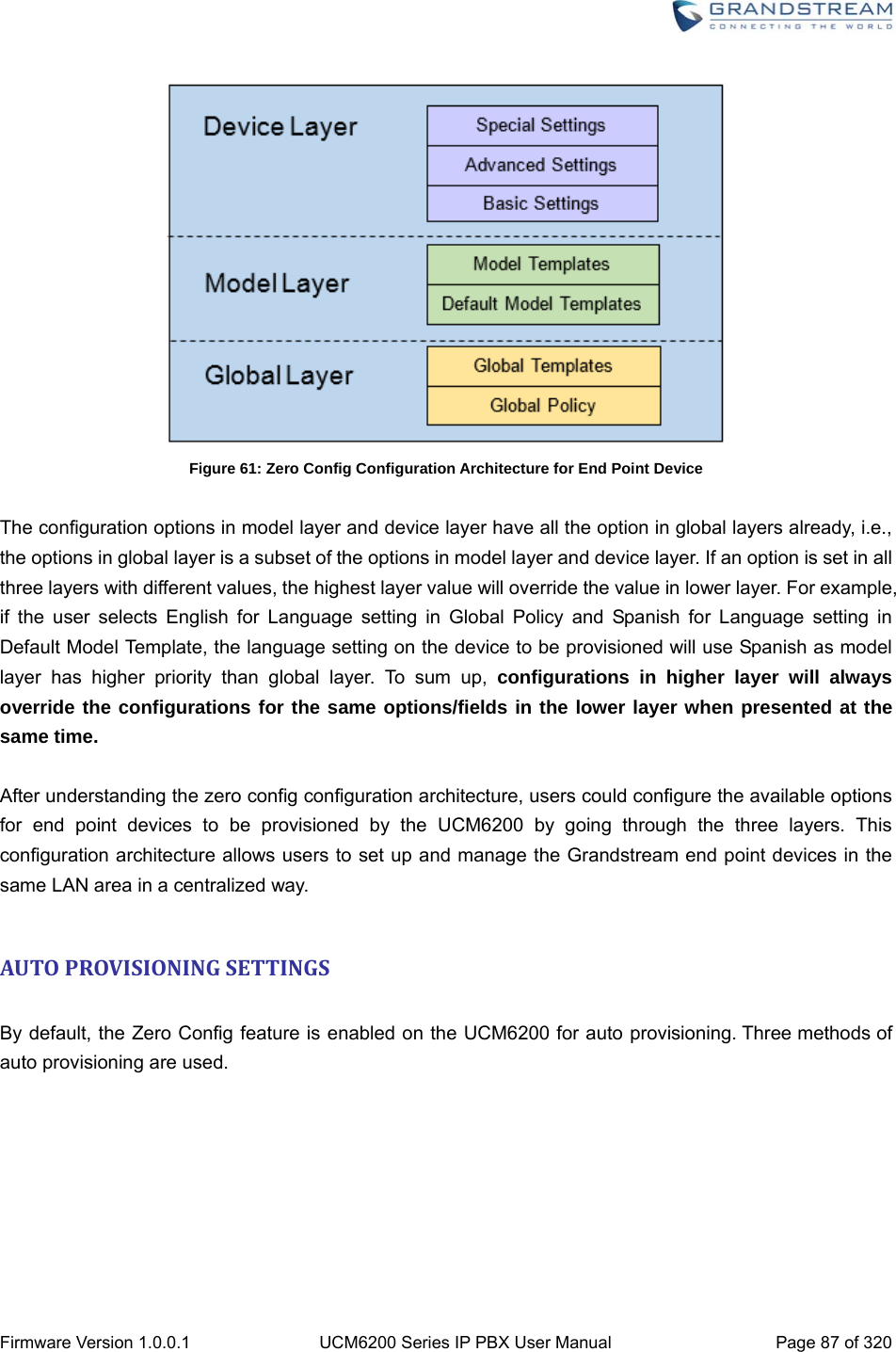
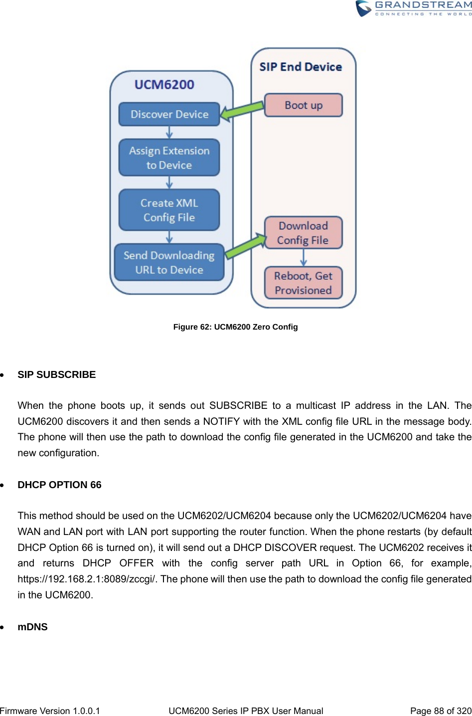
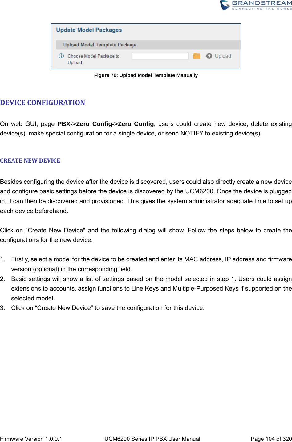
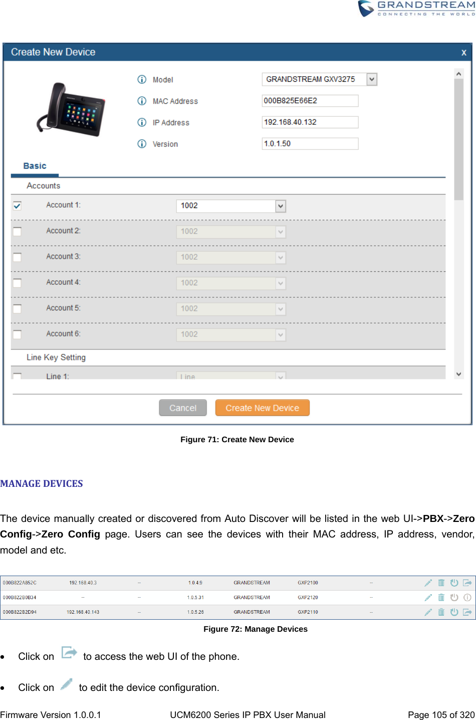
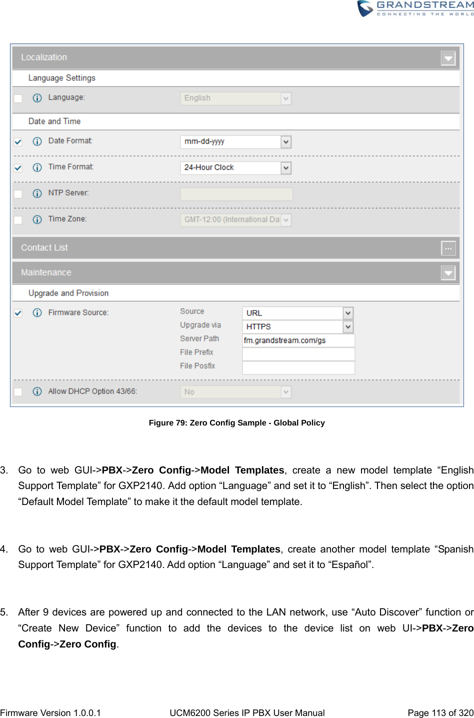
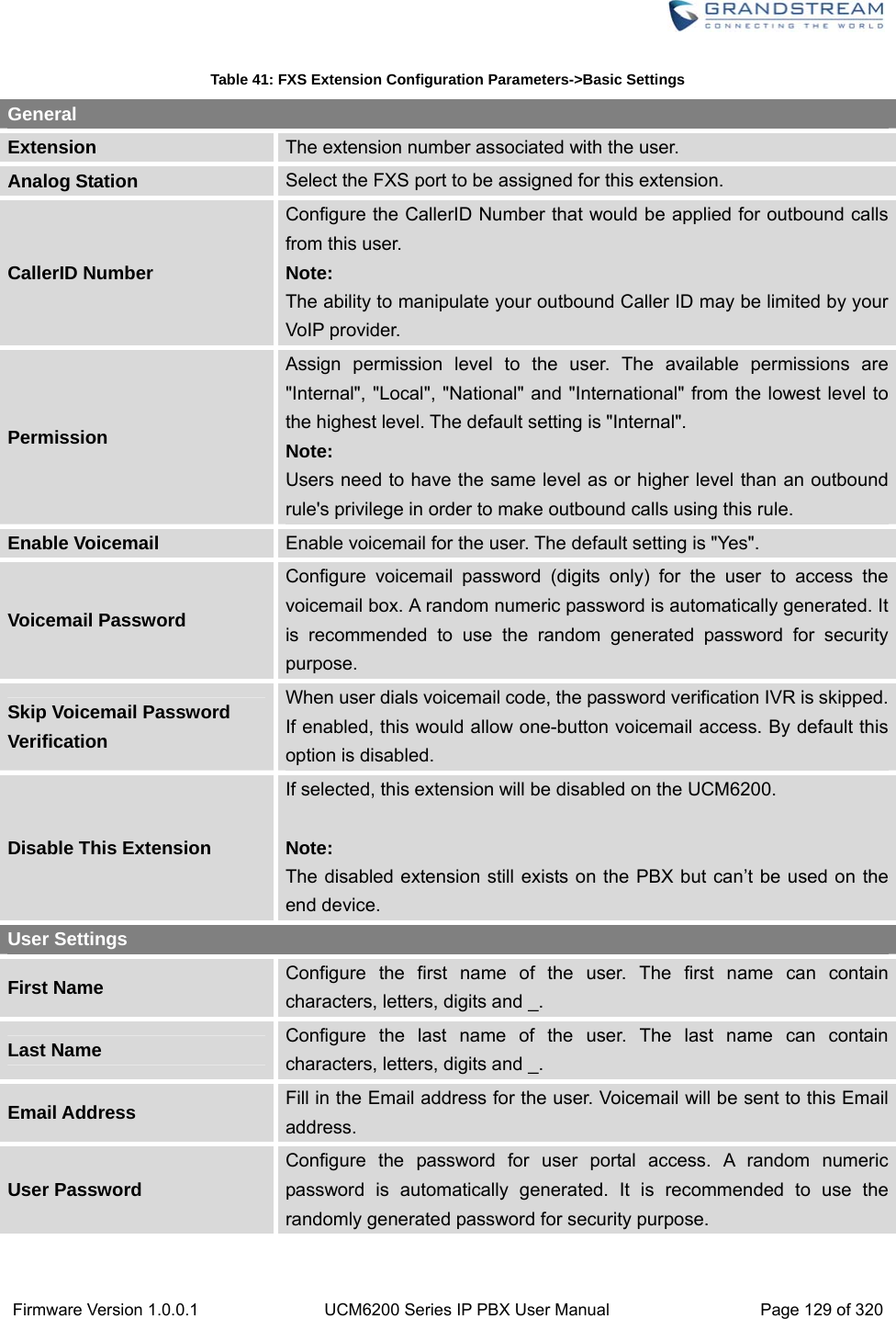
![Firmware Version 1.0.0.1 UCM6200 Series IP PBX User Manual Page 86 of 320 PROVISIONINGOVERVIEW Grandstream SIP Devices can be configured via Web interface as well as via configuration file through TFTP/HTTP/HTTPS download. All Grandstream SIP devices support a proprietary binary format configuration file and XML format configuration file. The UCM6200 provides a Plug and Play mechanism to auto-provision the Grandstream SIP devices in a zero configuration manner by generating XML config file and having the phone to download it within LAN area. This allows users to finish the installation with ease and start using the SIP devices in a managed way. To provision a phone, three steps are involved, i.e., discovery, configuration and provisioning. This section explains how Zero Config works on the UCM6200. The settings for this feature can be accessed via Web UI->PBX->Zero Config. CONFIGURATIONARCHITECTUREFORENDPOINTDEVICE Started from firmware version 1.0.7.10, the end point device configuration in zero config is divided into the following three layers with priority from the lowest to the highest: Global This is the lowest layer. Users can configure the most basic options that could apply to all Grandstream SIP devices during provisioning via Zero config. Model In this layer, users can define model-specific options for the configuration template. Device This is the highest layer. Users can configure device-specific options for the configuration for individual device here. Each layer also has its own structure in different levels. Please see figure below. The details for each layer are explained in sections [GLOBAL CONFIGURATION], [MODEL CONFIGURATION] and [DEVICE CONFIGURATION].](https://usermanual.wiki/Grandstream-Networks/UCM6208.Users-Manual-Part-One/User-Guide-3044584-Page-87.png)
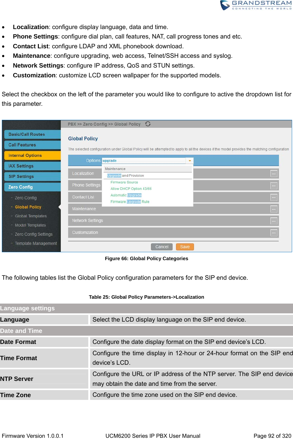
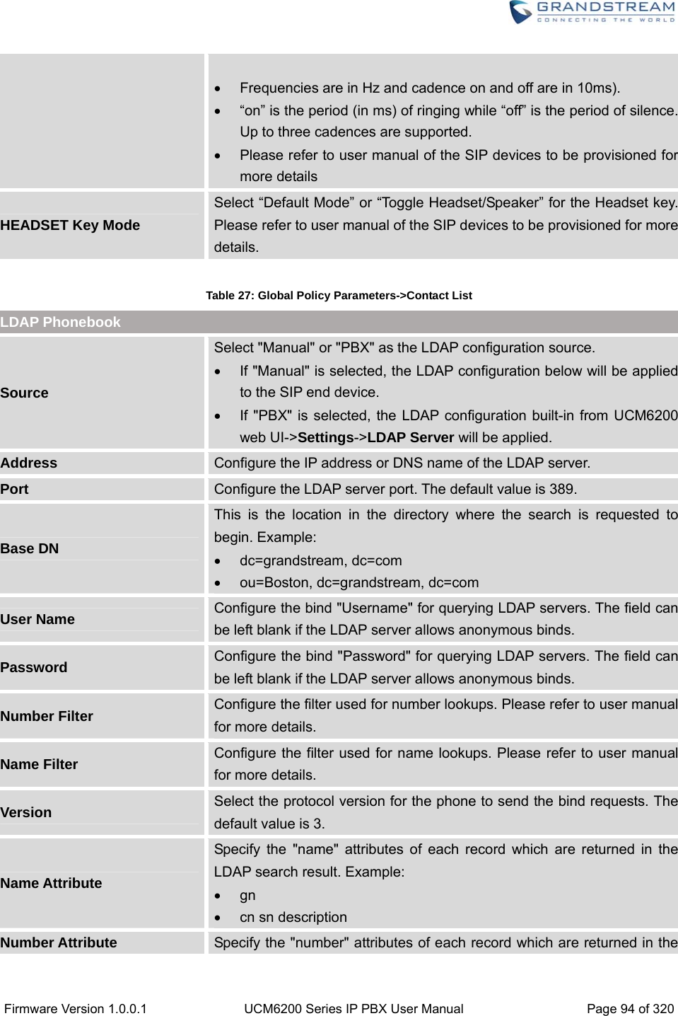
![Firmware Version 1.0.0.1 UCM6200 Series IP PBX User Manual Page 93 of 320 Table 26: Global Policy Parameters->Phone Settings Default Call Settings Dial Plan Configure the default dial plan rule. For syntax and examples, please refer to user manual of the SIP devices to be provisioned for more details.Enable Call Features When enabled, “Do Not Disturb”, “Call Forward” and other call features can be used via the local feature code on the phone. Otherwise, the ITSP feature code will be used. Use # as Dial Key If set to “Yes”, pressing the number key “#” will immediately dial out the input digits. Auto Answer by Call-info If set to "Yes", the phone will automatically turn on the speaker phone to answer incoming calls after a short reminding beep, based on the SIP Call-Info header sent from the server/proxy. The default setting is enabled. NAT Traversal Configure which NAT traversal mechanism will be enabled on the endpoint device. If set to "STUN" and STUN server is configured, the phone system will periodically send STUN message to the SUTN server to get the public IP address of its NAT environment and keep the NAT port open. STUN will not work if the NAT is symmetric type. If set to “Keep-alive”, the phone system will send the STUN packets to maintain the connection that is first established during registration of the phone. The “Keep-alive” packets will fool the NAT device into keeping the connection open and this allows the host server to send SIP requests directly to the registered phone. If it needs to use OpenVPN to connect host server, it needs to set it to “VPN”. If the firewall and the SIP device behind the firewall are both able to use UPNP, it can be set to “UPNP”. The both parties will negotiate to use which port to allow SIP through. The default setting is "Keep-alive". Use Random Port Configure whether to allow the endpoint device to use random ports for both SIP and RTP messages. This is usually necessary when multiple phones are behind the same full cone NAT. The default setting is "No". Note: This parameter must be set to "No" for Direct IP Calling to work. General Settings Call Progress Tones Configure call progress tones including ring tone, dial tone, second dial tone, message waiting tone, ring back tone, call waiting tone, busy tone and reorder tone using the following syntax: f1=val, f2=val[, c=on1/ off1[- on2/ off2[- on3/ off3]]];](https://usermanual.wiki/Grandstream-Networks/UCM6208.Users-Manual-Part-One/User-Guide-3044584-Page-94.png)
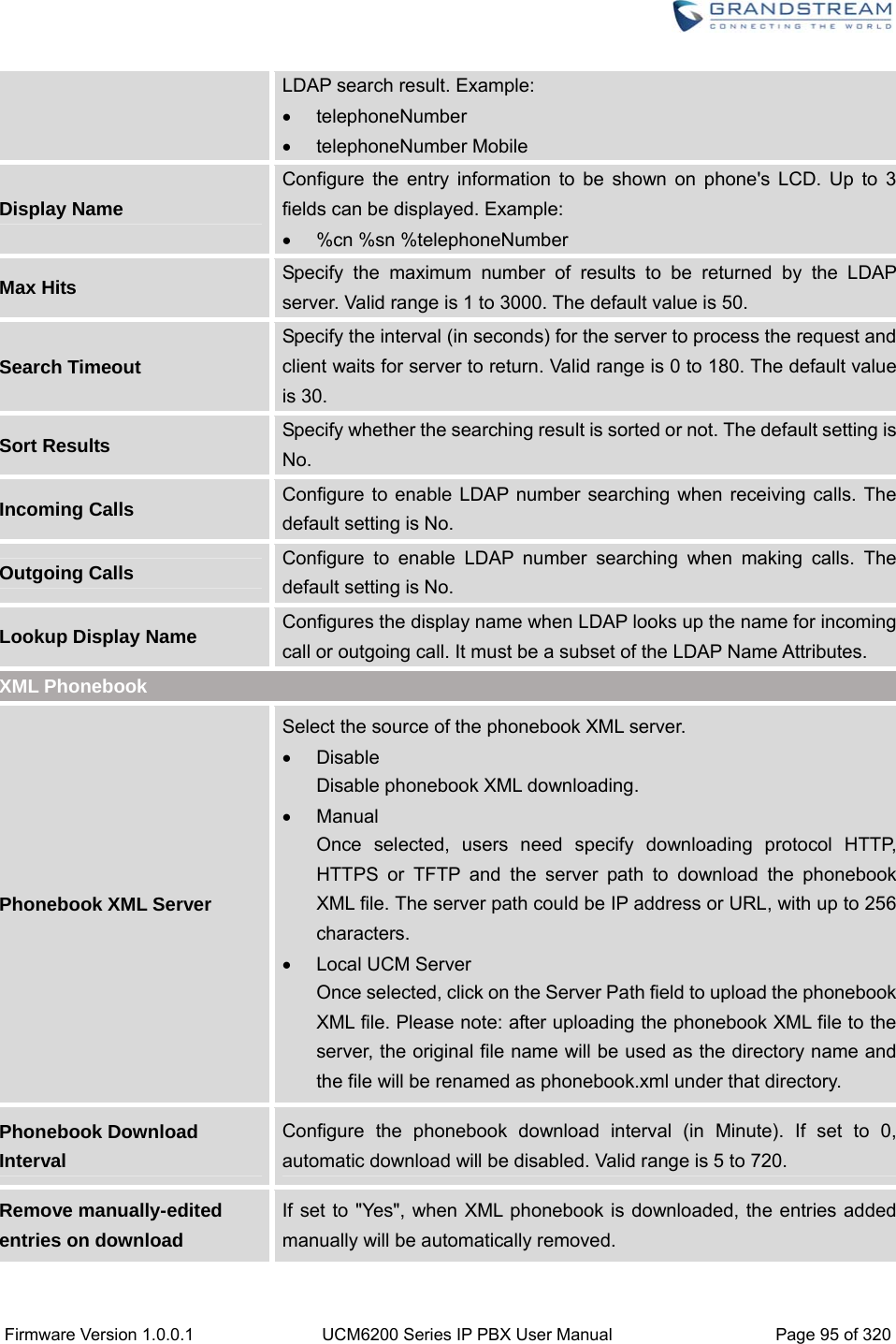
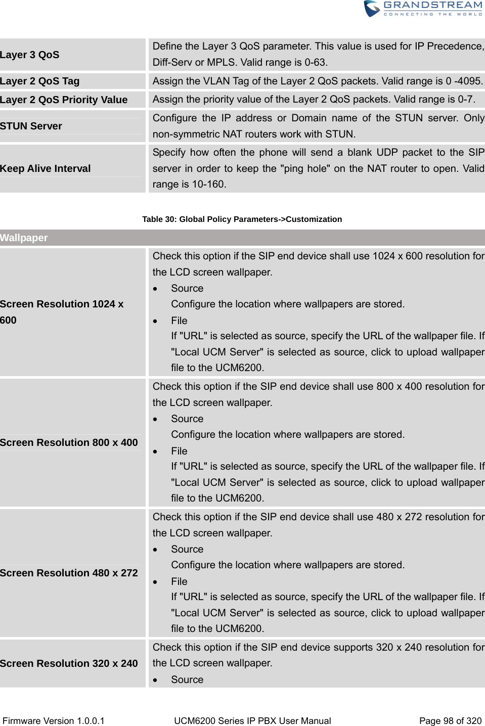
![Firmware Version 1.0.0.1 UCM6200 Series IP PBX User Manual Page 99 of 320 Configure the location where wallpapers are stored. File If "URL" is selected as source, specify the URL of the wallpaper file. If "Local UCM Server" is selected as source, click to upload wallpaper file to the UCM6200. GLOBALTEMPLATES Global Templates can be accessed in web GUI->PBX->Zero Config->Global Templates. Users can create multiple global templates with different sets of configurations and save the templates. Later on, when the user configures the device in Edit Device dialog->Advanced Settings, the user can select to use one of the global template for the device. Please refer to section [MANAGE DEVICES] for more details on using the global templates. When creating global template, users can select the categories and the parameters under each category to be used in the template. The global policy and the selected global template will both take effect when generating the config file. However, the selected global template has higher priority to the global policy when it comes to the same setting option/field. If the same option/field has different value configured in the global policy and the selected global template, the value for this option/field in the selected global template will override the value in global policy. Click on "Create New Template" to add a global template. Users will see the following configurations. Table 31: Create New Template Template Name Create a name to identify this global template. Description Provide a description for the global template. This is optional. Active Check this option to enable the global template. Click on to edit the global template. The window for editing global template is shown in the following figure. In the “Options” field, after entering the option name key word, the options containing the key word will be listed. Users could then select the options to be modified and click on “Add Option” to add it into the global template.](https://usermanual.wiki/Grandstream-Networks/UCM6208.Users-Manual-Part-One/User-Guide-3044584-Page-100.png)
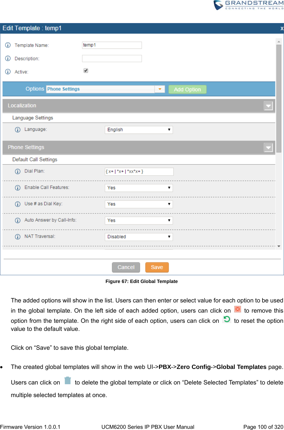
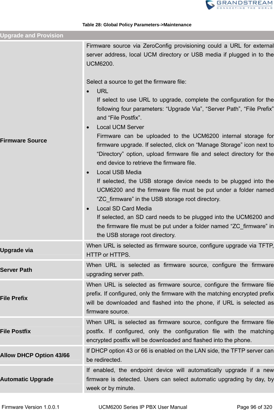
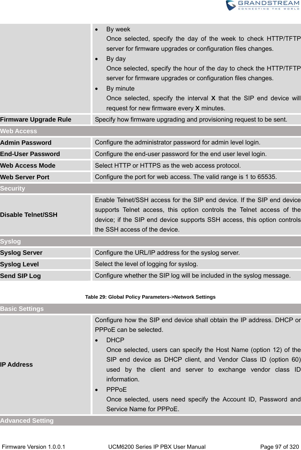
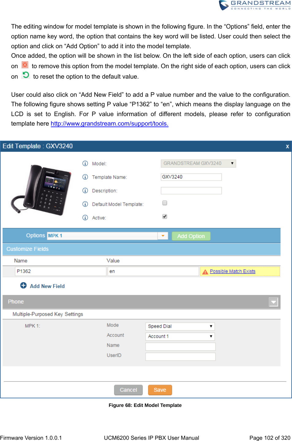
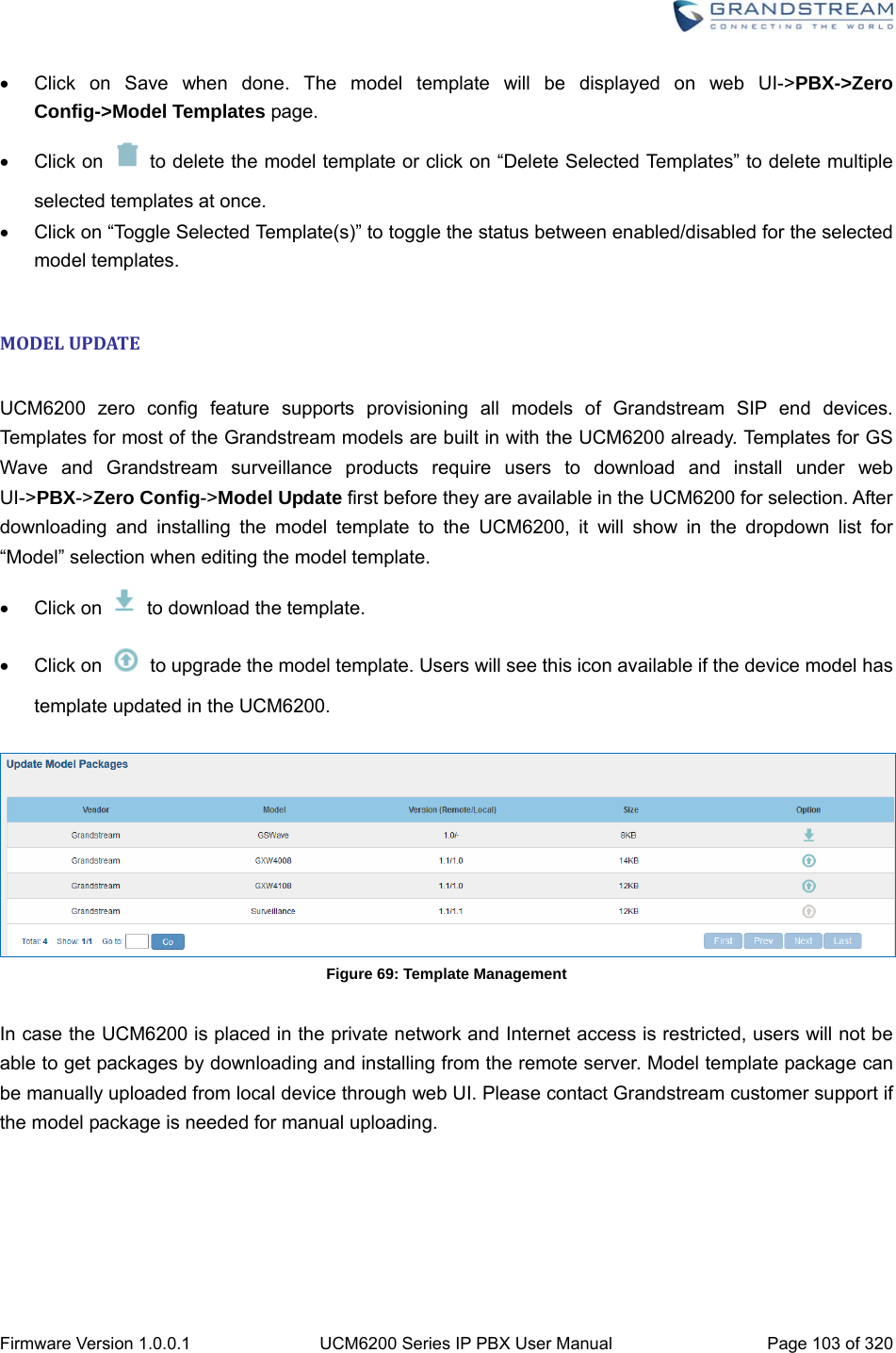
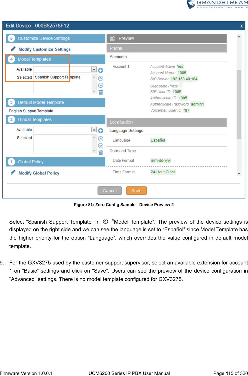
![Firmware Version 1.0.0.1 UCM6200 Series IP PBX User Manual Page 101 of 320 Click on “Toggle Selected Template(s)” to toggle the status between enabled/disabled for the selected templates. MODELCONFIGURATIONMODELTEMPLATES Model layer configuration allows users to apply model-specific configurations to different devices. Users could create/edit/delete a model template by accessing web GUI, page PBX->Zero Config->Model Templates. If multiple model templates are created and enabled, when the user configures the device in Edit Device dialog->Advanced Settings, the user can select to use one of the model template for the device. Please refer to section [MANAGE DEVICES] for more details on using the model template. For each created model template, users can assign it as default model template. If assigned as default model template, the values in this model template will be applied to all the devices of this model. There is always only one default model template that can be assigned at one time on the UCM6200. The selected model template and the default model template will both take effect when generating the config file for the device. However, the model template has higher priority to default model template when it comes to the same setting option/field. If the same option/field has different value configured in the default model template and the selected model template, the value for this option/field in the selected model template will override the value in default model template. Click on “Create New Template” to add a model template. Table 32: Create New Model Template Model Select a model to apply this template. The supported Grandstream models are listed in the dropdown list for selection. Template Name Create a name for the model template. Description Enter a description for the model template. This is optional. Default Model Template Select to assign this model template as the default model template. The value of the option in default model template will be overridden if other selected model template has a different value for the same option. Active Check this option to enable the model template. Click on to edit the model template.](https://usermanual.wiki/Grandstream-Networks/UCM6208.Users-Manual-Part-One/User-Guide-3044584-Page-102.png)
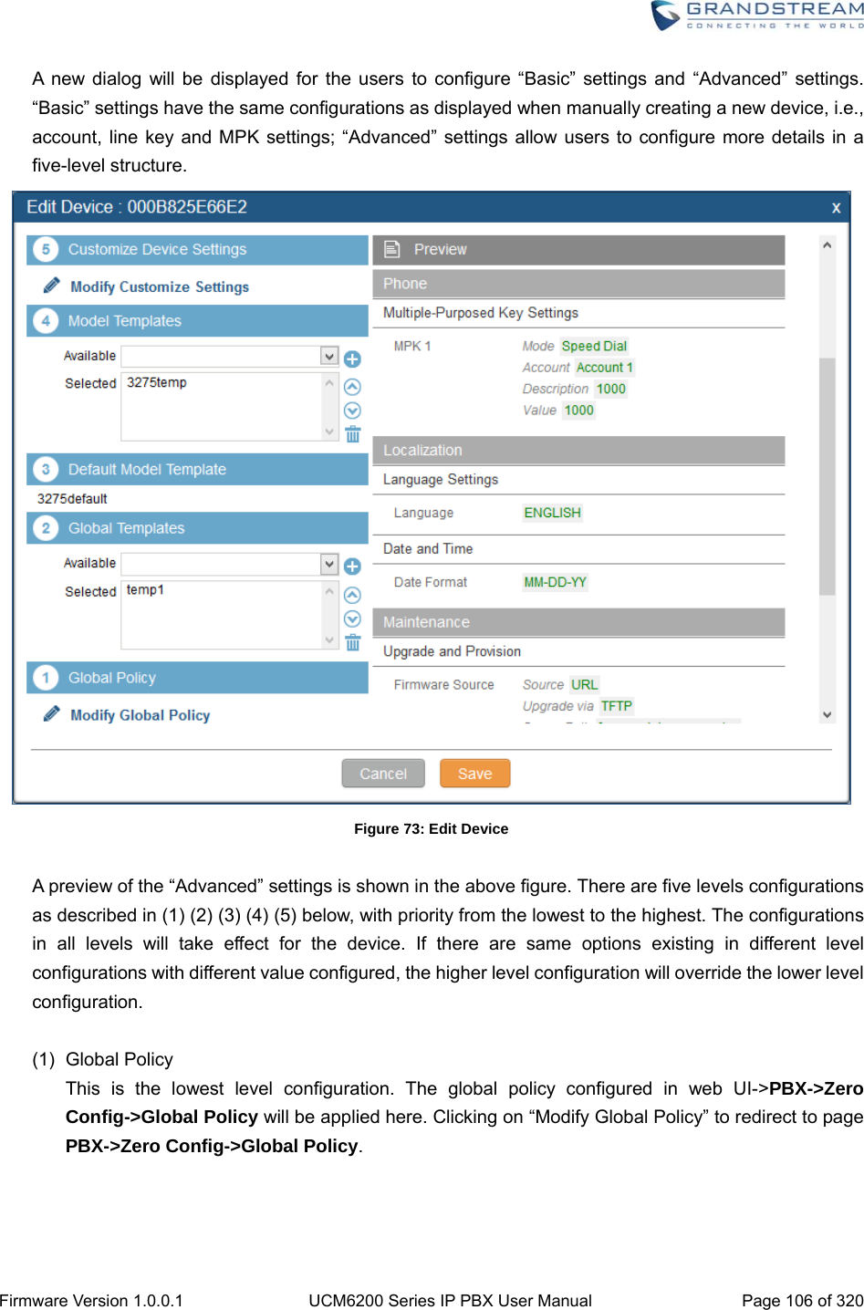
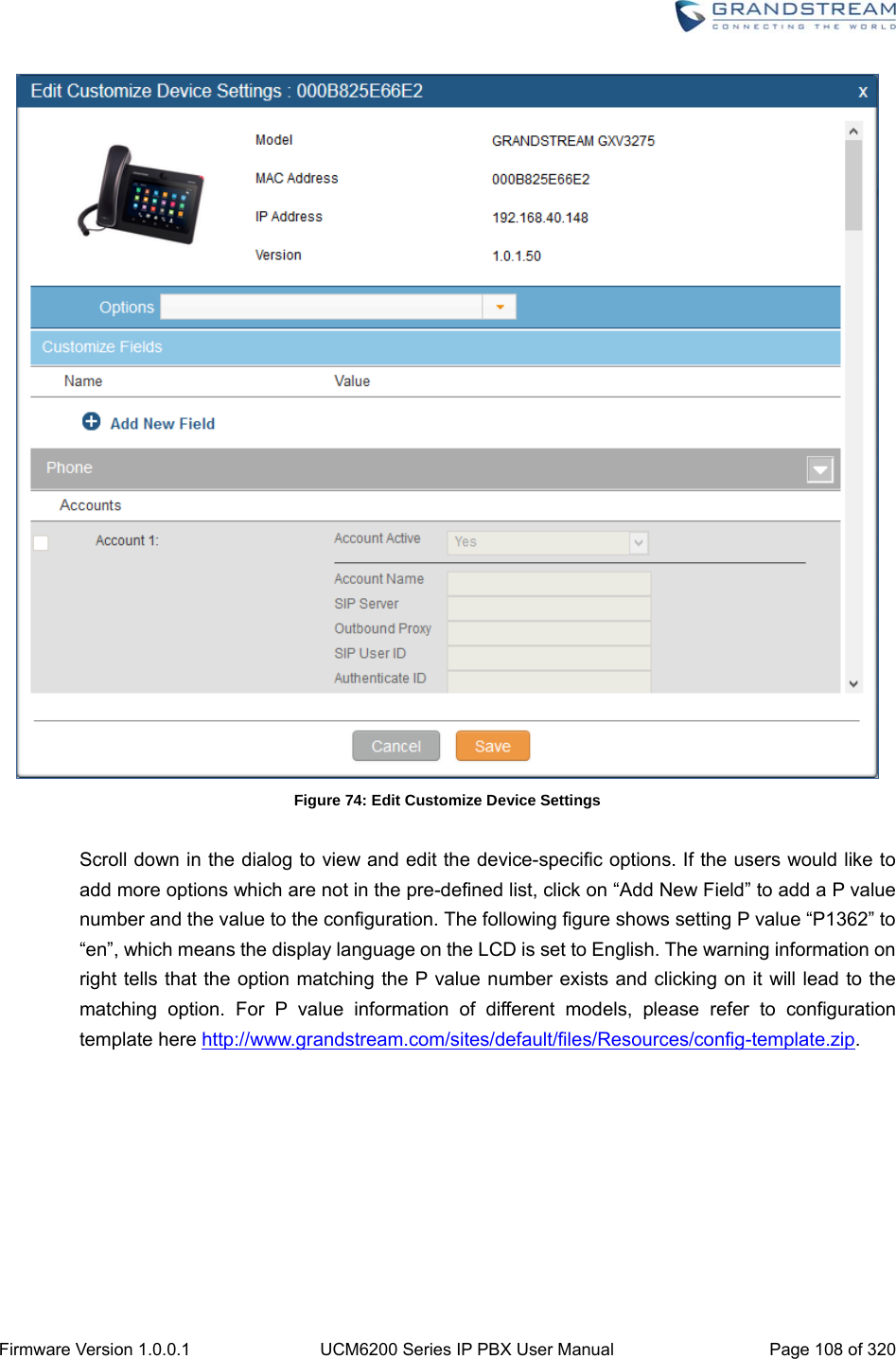
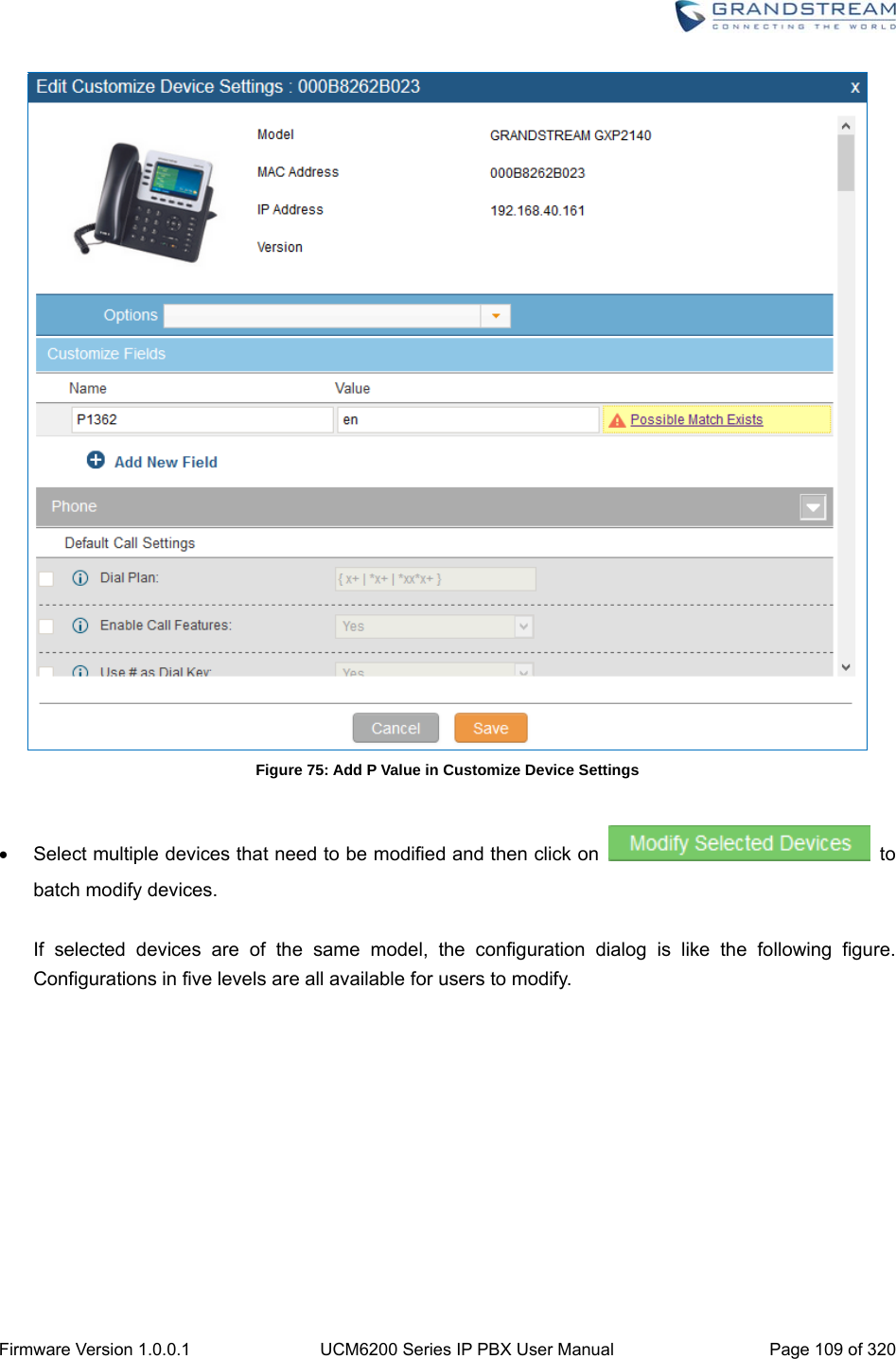
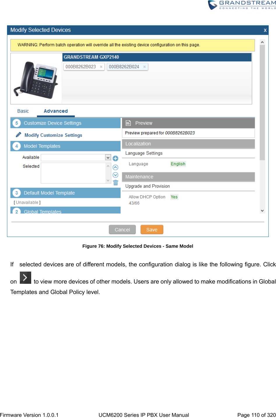
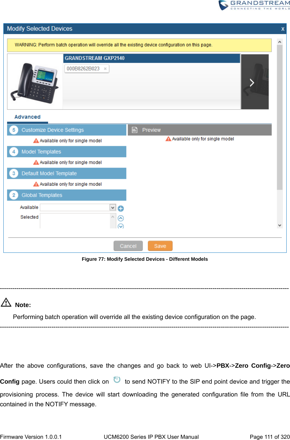
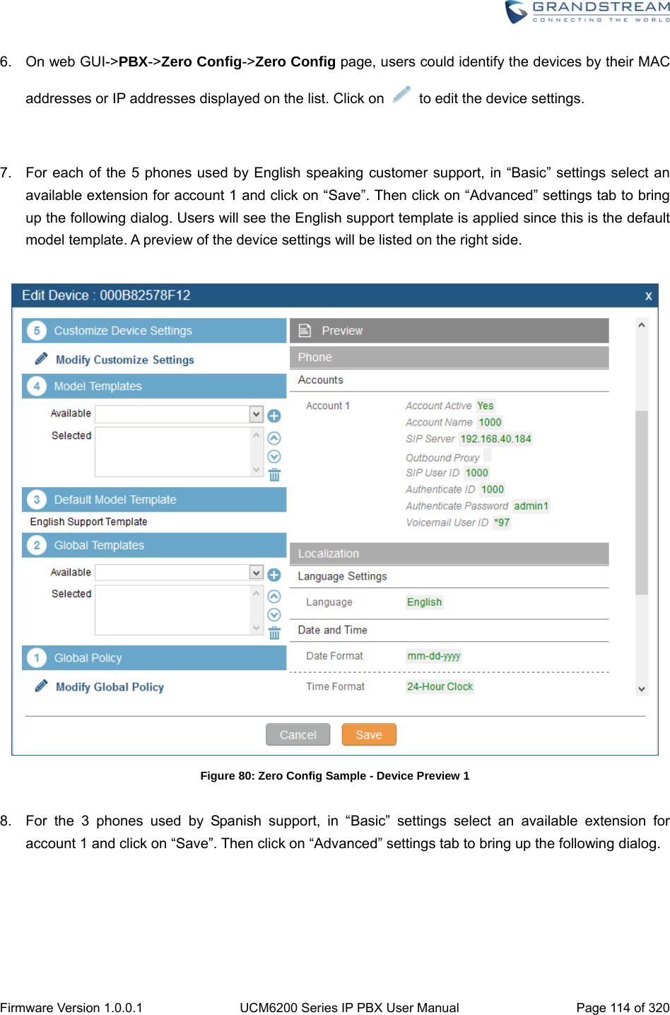
![Firmware Version 1.0.0.1 UCM6200 Series IP PBX User Manual Page 107 of 320 (2) Global Templates Select a global template to be used for the device and click on to add. Multiple global templates can be selected and users can arrange the priority by adjusting orders via and . All the selected global templates will take effect. If the same option exists on multiple selected global templates, the value in the template with higher priority will override the one in the template with lower priority. Click on to remove the global template from the selected list. (3) Default Model Template Default Model Template will be applied to the devices of this model. Default model template can be configured in model template under web UI->PBX->Zero Config->Model Templates page. Please see default model template option in [Table 32: Create New Model Template]. (4) Model Templates Select a model template to be used for the device and click on to add. Multiple global templates can be selected and users can arrange the priority by adjusting orders via and . All the selected model templates will take effect. If the same option exists on multiple selected model templates, the value in the template with higher priority will override the one in the template with lower priority. Click on to remove the model template from the selected list. (5) Customize Device Settings This is the highest level configuration for the device. Click on “Modify Customize Device Settings” and following dialog will show.](https://usermanual.wiki/Grandstream-Networks/UCM6208.Users-Manual-Part-One/User-Guide-3044584-Page-108.png)


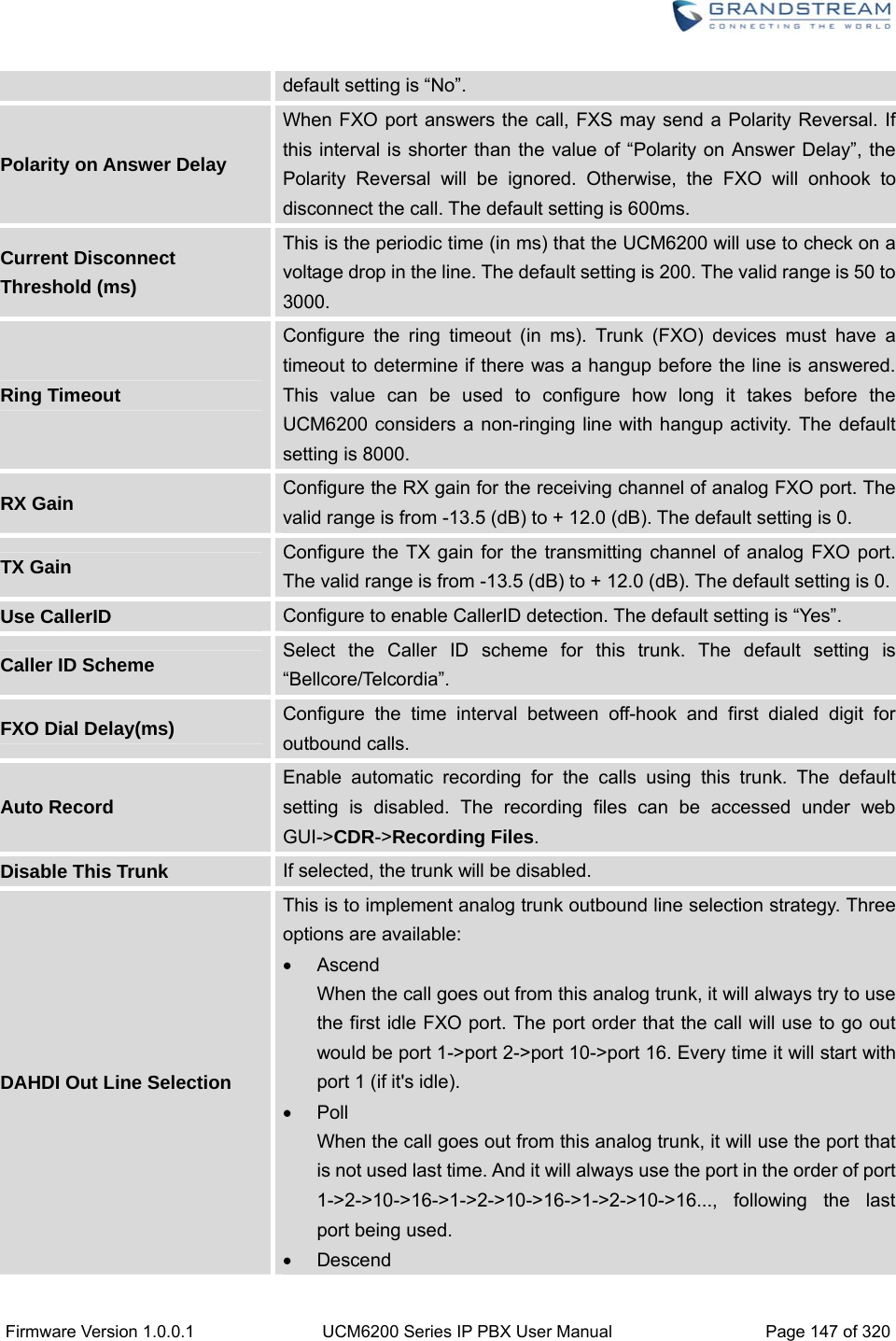
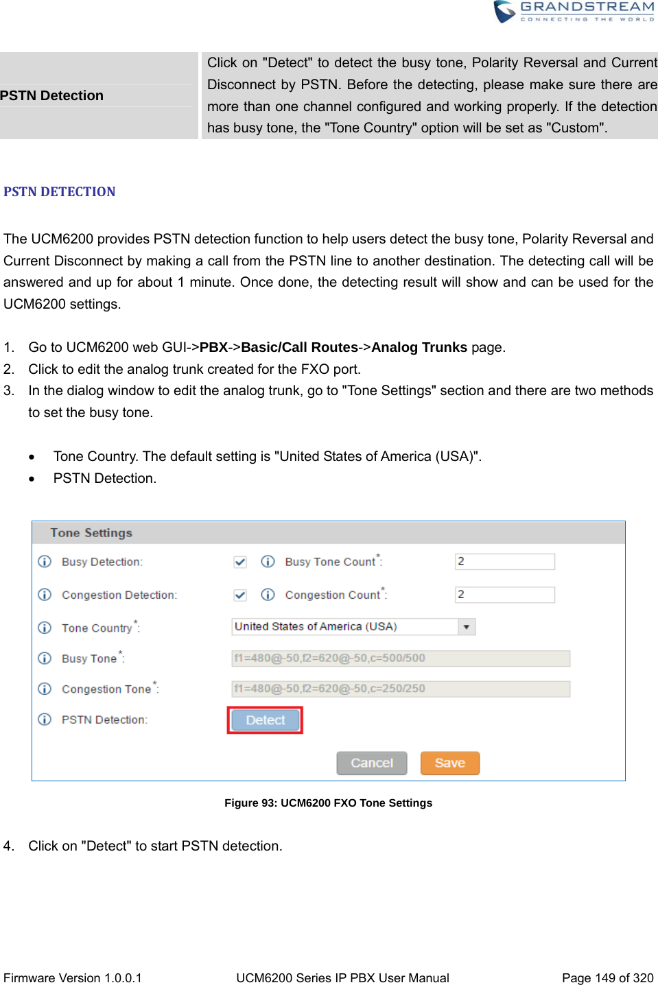
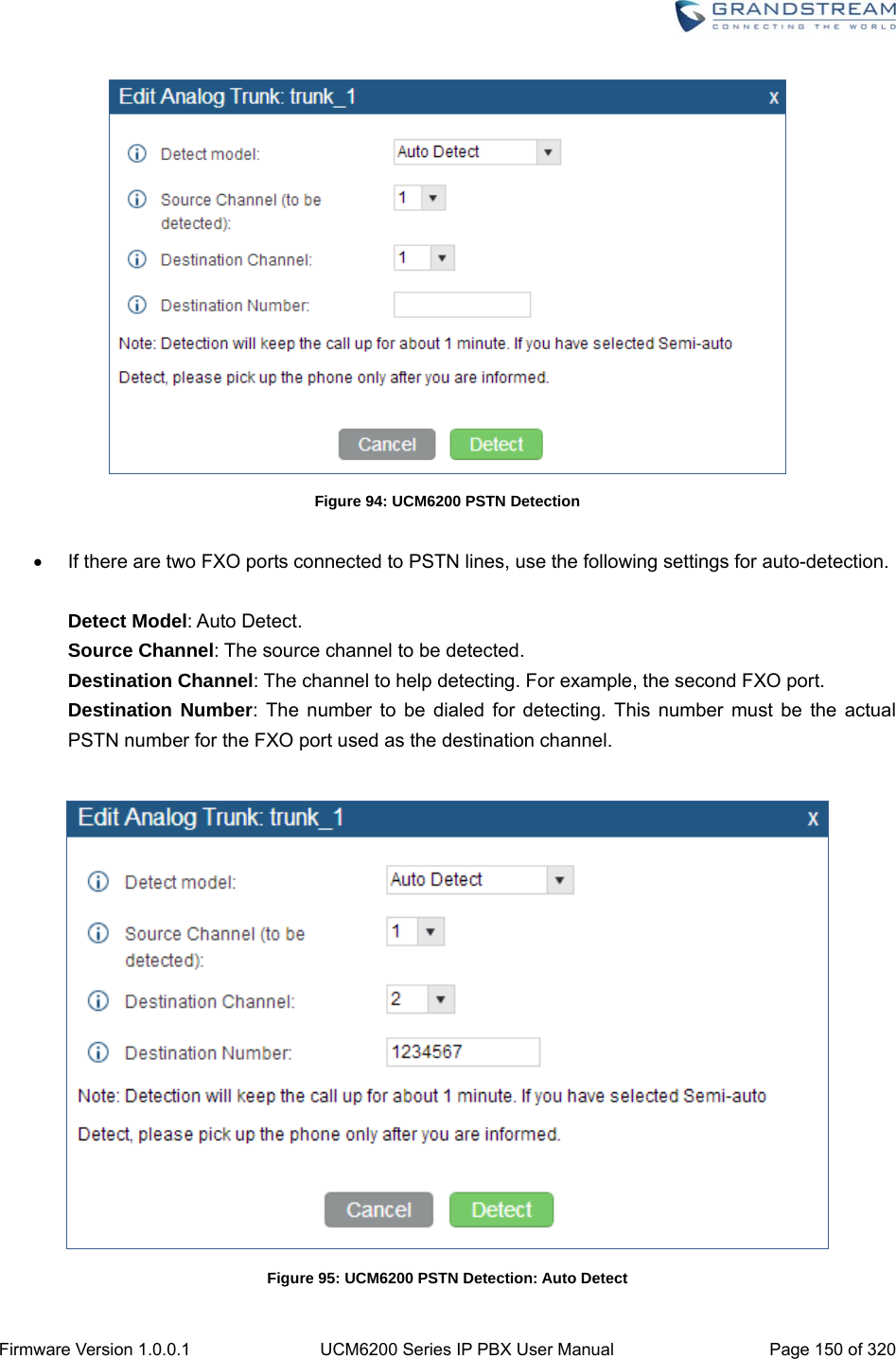
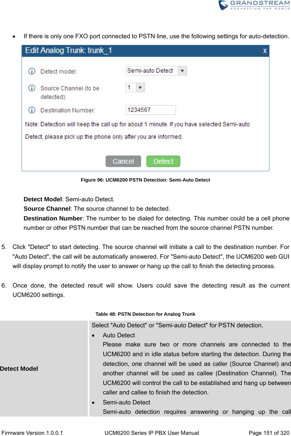
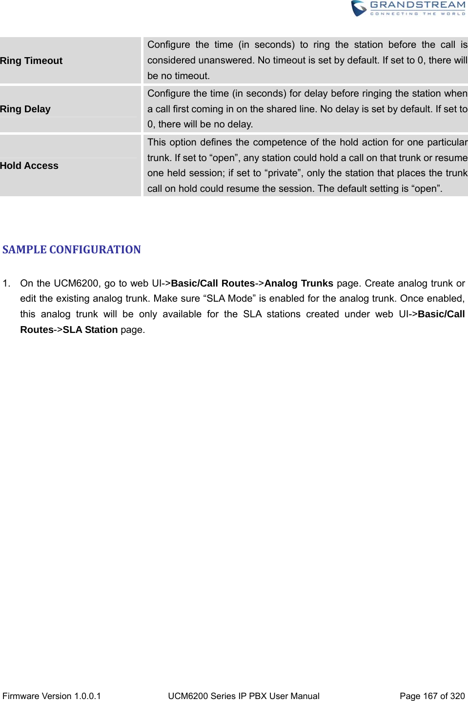
![Firmware Version 1.0.0.1 UCM6200 Series IP PBX User Manual Page 148 of 320 When the call goes out from this analog trunk, it will always try to use the last idle FXO port. The port order that the call will use to go out would be port 16->port 10->port 2->port 1. Every time it will start with port 16 (if it's idle). The default setting is “Ascend” mode. Tone Settings Busy Detection Busy Detection is used to detect far end hangup or for detecting busy signal. The default setting is "Yes". Busy Tone Count If "Busy Detection" is enabled, users can specify the number of busy tones to be played before hanging up. The default setting is 2. Better results might be achieved if set to 4, 6 or even 8. Please note that the higher the number is, the more time is needed to hangup the channel. However, this might lower the probability to get random hangup. Congestion Detection Congestion detection is used to detect far end congestion signal. The default setting is "Yes". Congestion Count If "Congestion Detection" is enabled, users can specify the number of congestion tones to wait for. The default setting is 2. Tone Country Select the country for tone settings. If "Custom" is selected, users could manually configure the values for Busy Tone and Congestion Tone. The default setting is "United States of America (USA)". Busy Tone Syntax: f1=val[@level][,f2=val[@level]],c=on1/off1[-on2/off2[-on3/off3]]; Frequencies are in Hz and cadence on and off are in ms. Frequencies Range: [0, 4000) Busy Level Range: (-300, 0) Cadence Range: [0, 16383]. Select Tone Country "Custom" to manually configure Busy Tone value. Default value: f1=480@-50,f2=620@-50,c=500/500 Congestion Tone Syntax: f1=val[@level][,f2=val[@level]],c=on1/off1[-on2/off2[-on3/off3]]; Frequencies are in Hz and cadence on and off are in ms. Frequencies Range: [0, 4000) Busy Level Range: (-300, 0) Cadence Range: [0, 16383]. Select Tone Country "Custom" to manually configure Busy Tone value. Default value: f1=480@-50,f2=620@-50,c=250/250](https://usermanual.wiki/Grandstream-Networks/UCM6208.Users-Manual-Part-One/User-Guide-3044584-Page-149.png)

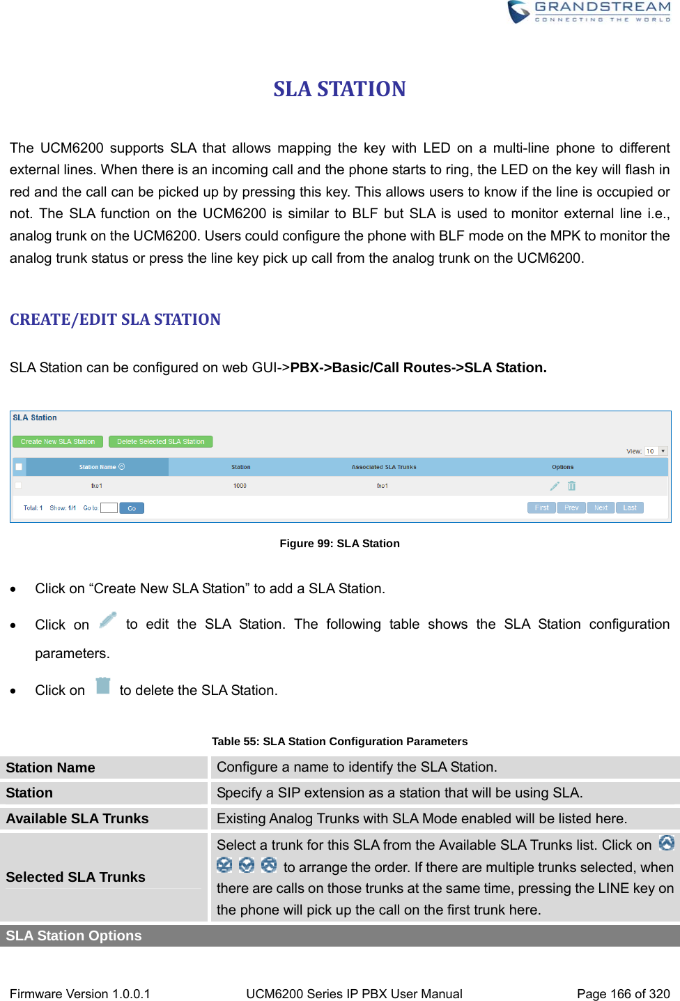
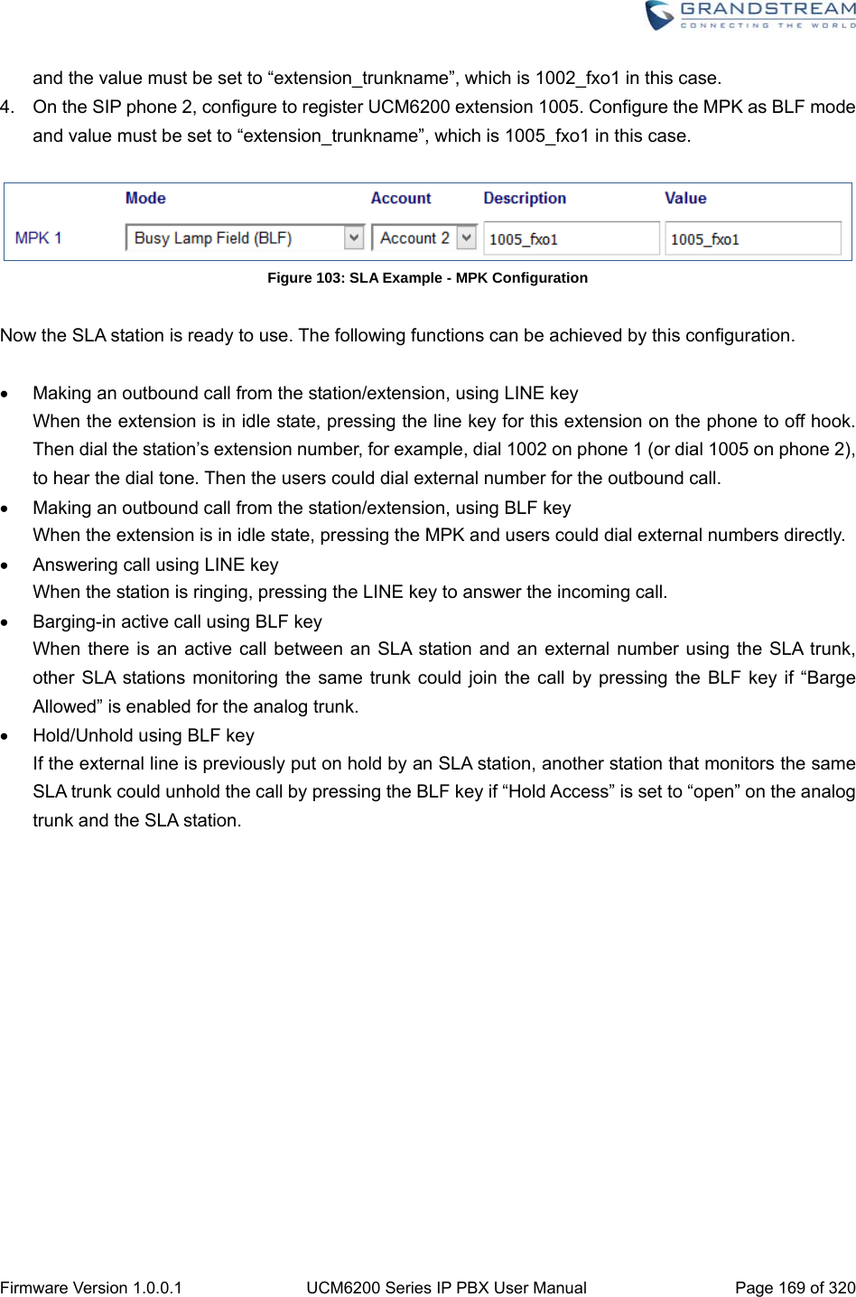
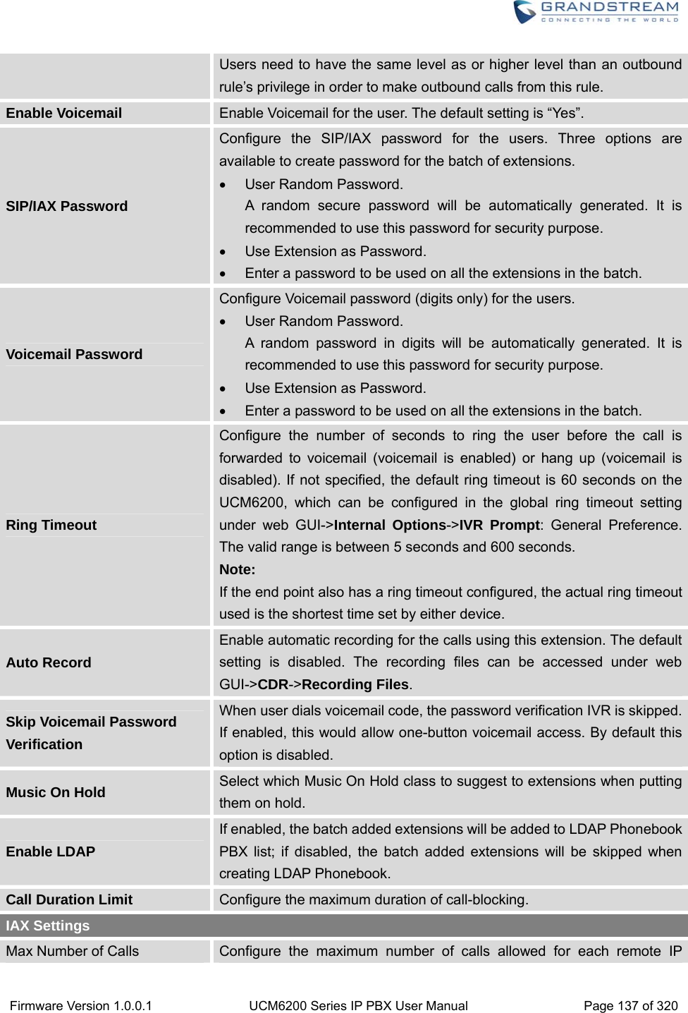
![Firmware Version 1.0.0.1 UCM6200 Series IP PBX User Manual Page 168 of 320 Figure 100: Enable SLA Mode for Analog Trunk Click on “Save”. The analog trunk will be listed with trunk mode “SLA”. Figure 101: Analog Trunk with SLA Mode Enabled 2. On the UCM6200, go to web UI->Basic/Call Routes->SLA Station page, click on “Create New SLA Station”. Please refer to section [CREATE/EDIT SLA STATION] for the configuration parameters. Users can create one or more SLA stations to monitor the analog trunk. The following figure shows two stations, 1002 and 1005, are configured to be associated with SLA trunk “fxo1”. Figure 102: SLA Example - SLA Station 3. On the SIP phone 1, configure to register UCM6200 extension 1002. Configure the MPK as BLF mode](https://usermanual.wiki/Grandstream-Networks/UCM6208.Users-Manual-Part-One/User-Guide-3044584-Page-169.png)