Grandstream Networks UCM6208 IP PBX User Manual 1 UCM62xx usermanual ok
Grandstream Networks, Inc. IP PBX 1 UCM62xx usermanual ok
UserManual.wiki
>
Grandstream Networks
>
UCM6208 User Manual
>
Users Manual Part Two
Contents
1.
Users Manual Part One
2.
Users Manual Part Two
Users Manual Part Two
Navigation menu
Upload a User Manual
Namespaces
Wiki Guide
HTML
PDF
Info
Views
User Manual
Discussion / Help
Navigation
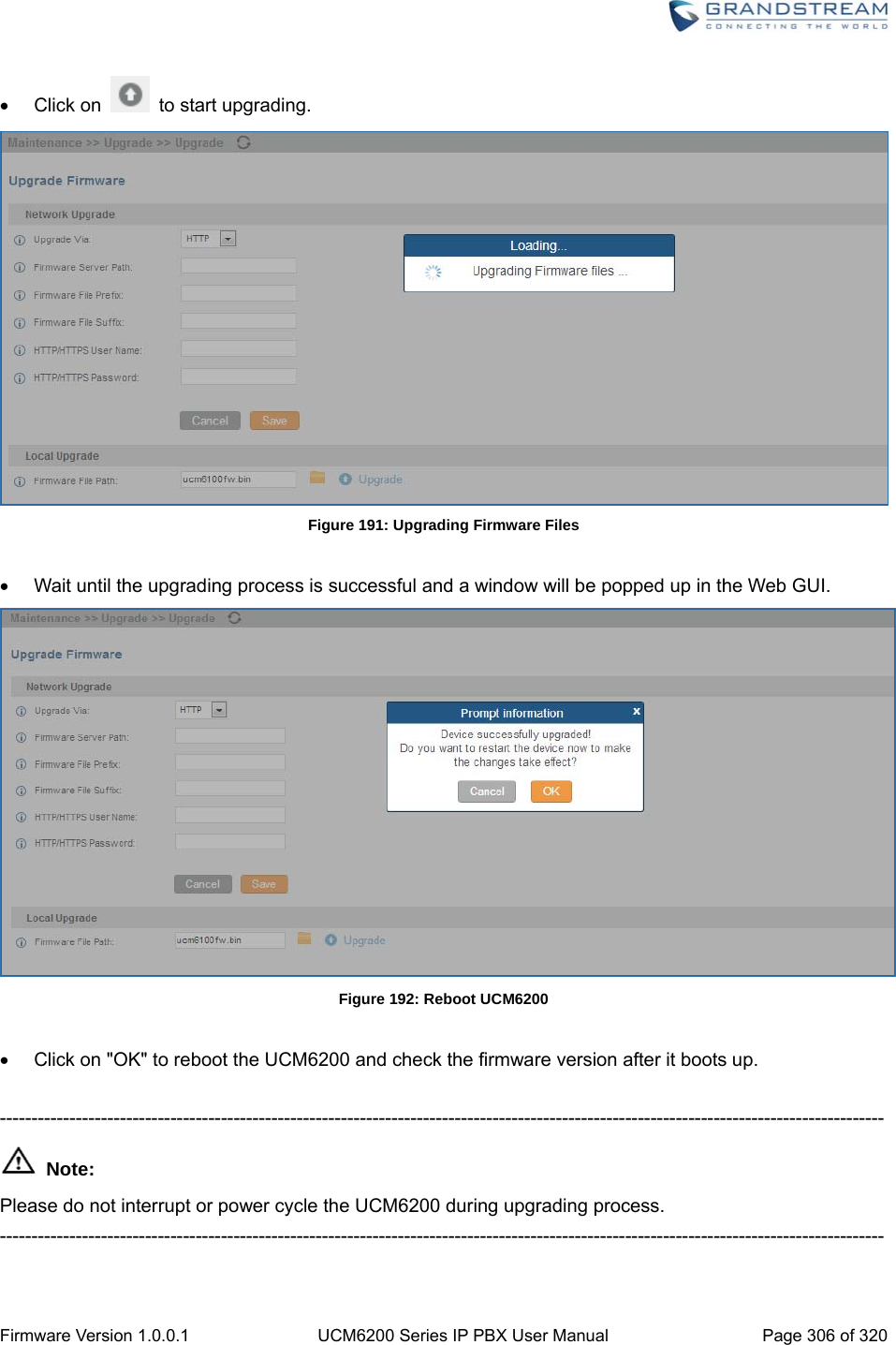
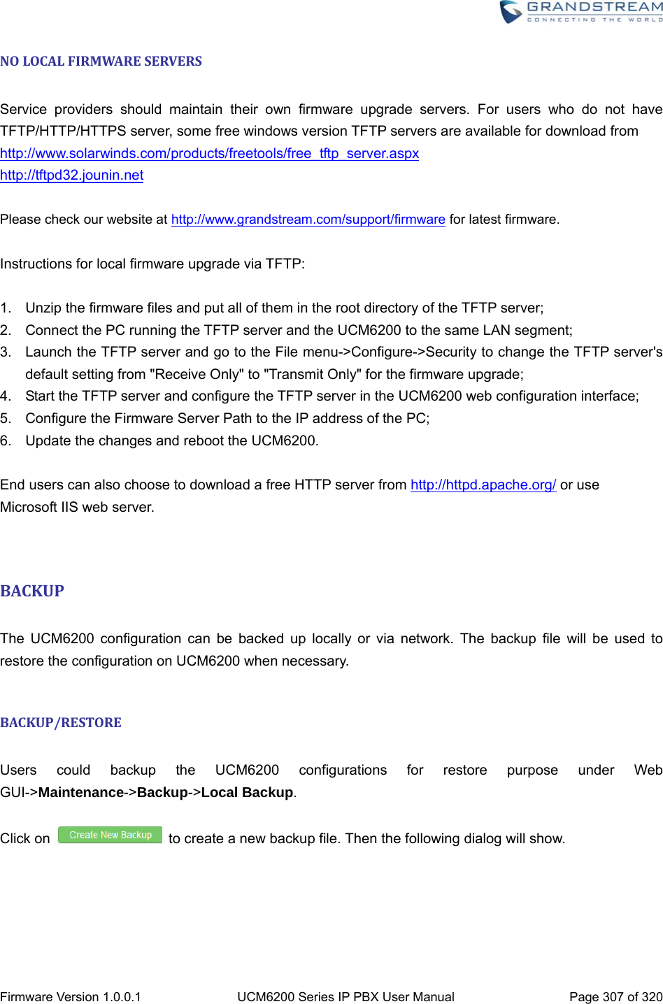
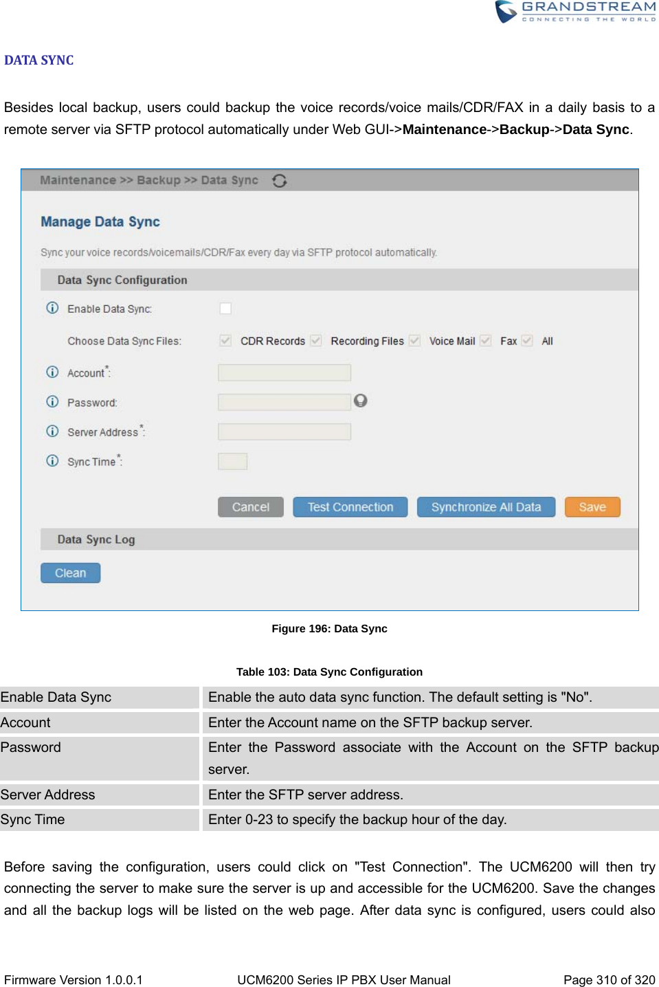
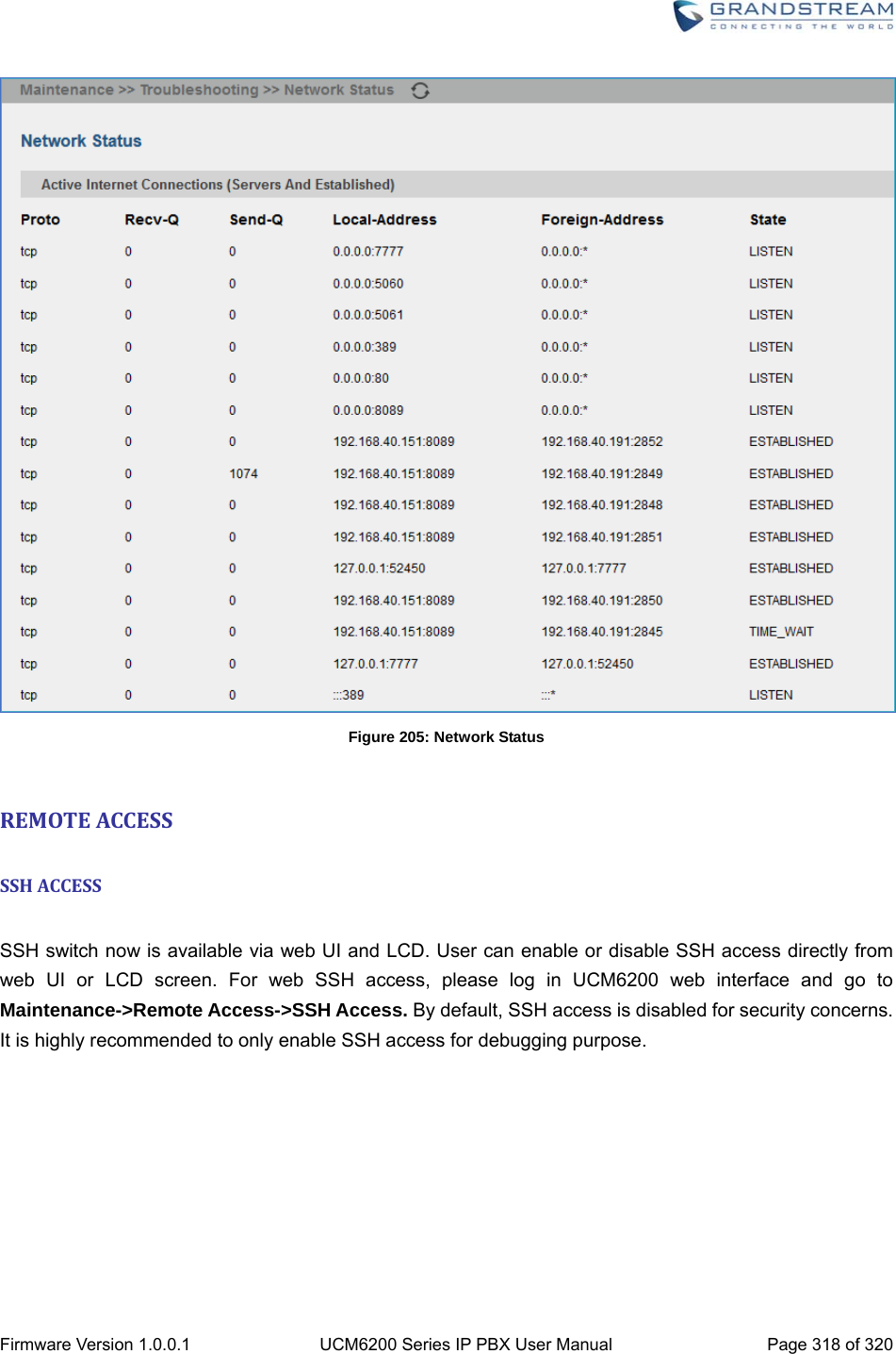
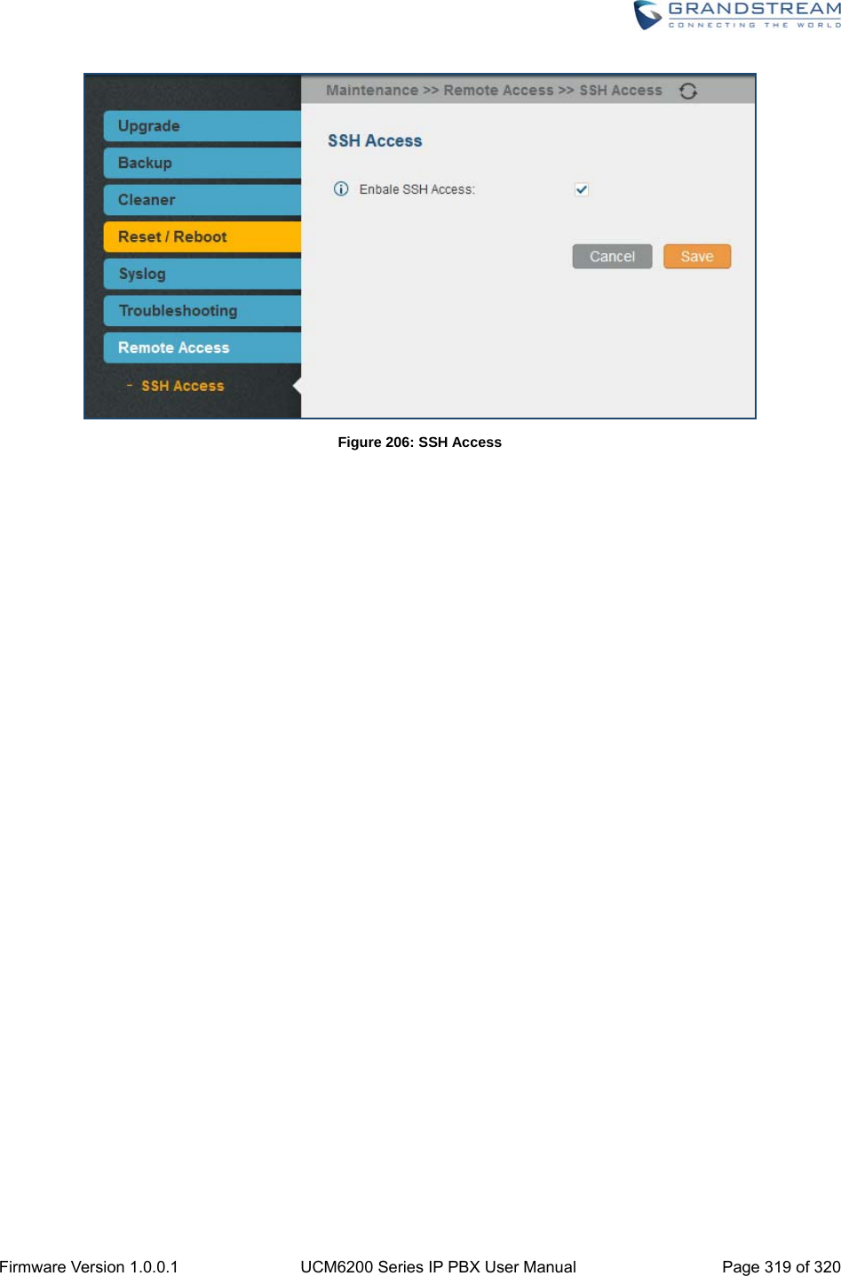
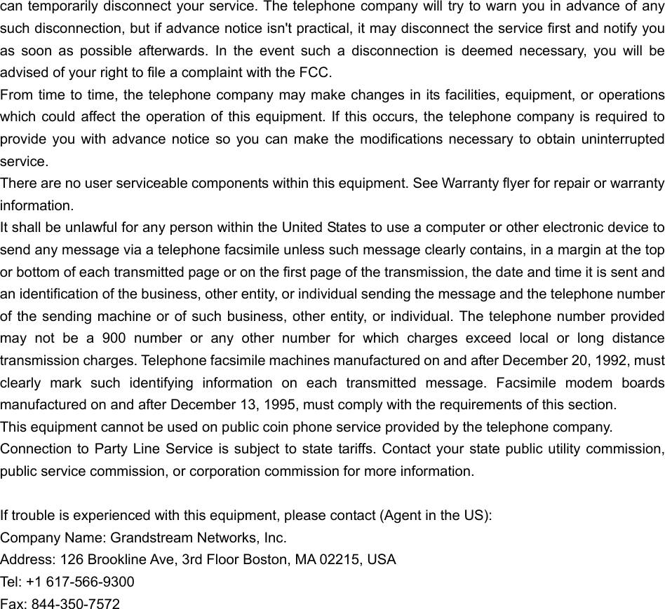
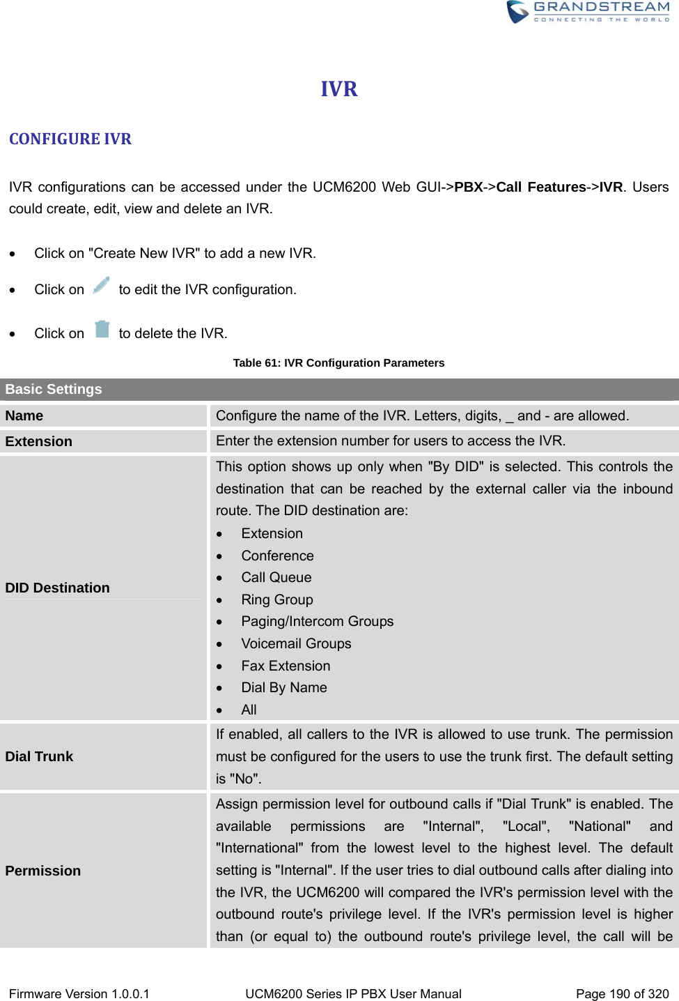
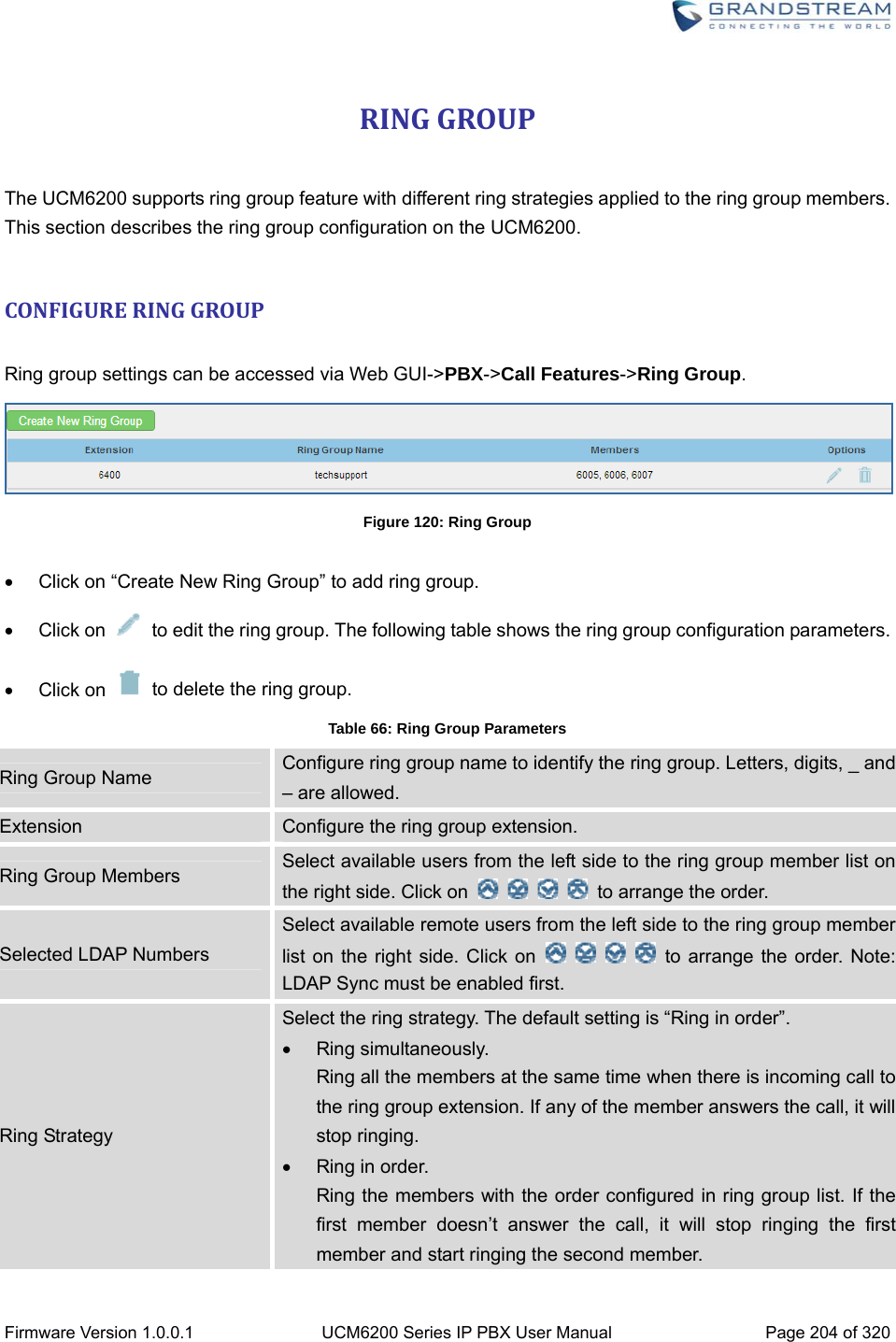
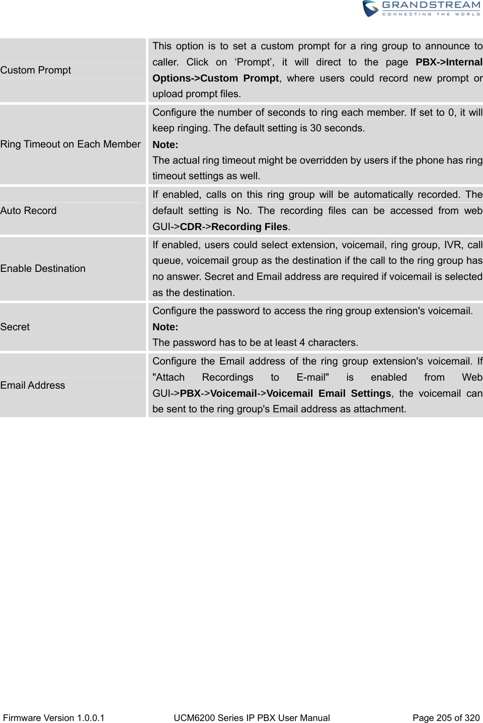
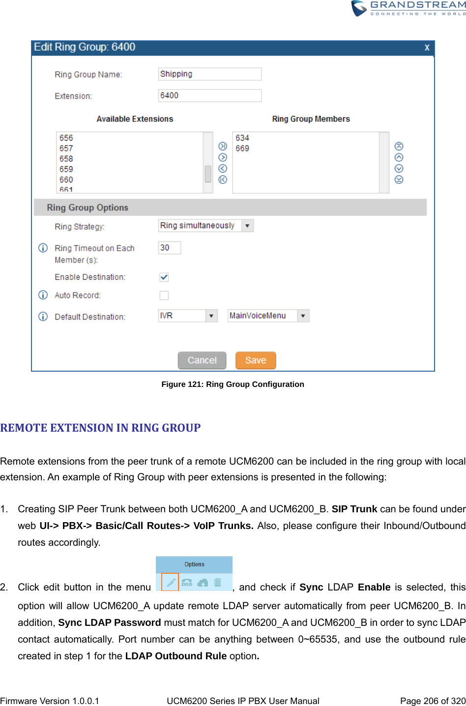
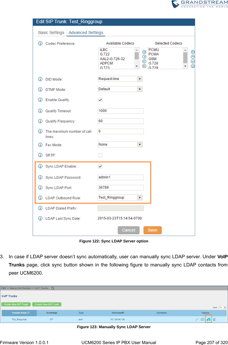
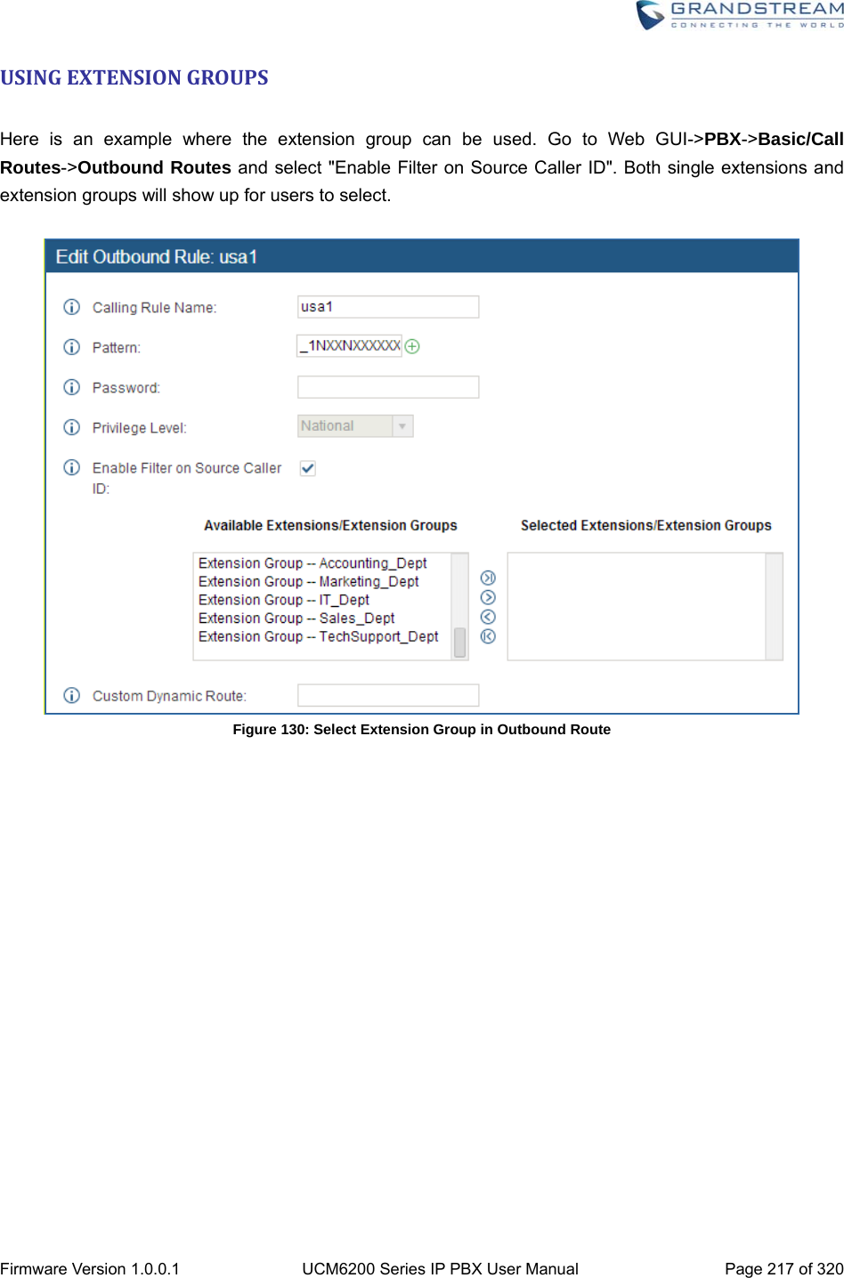
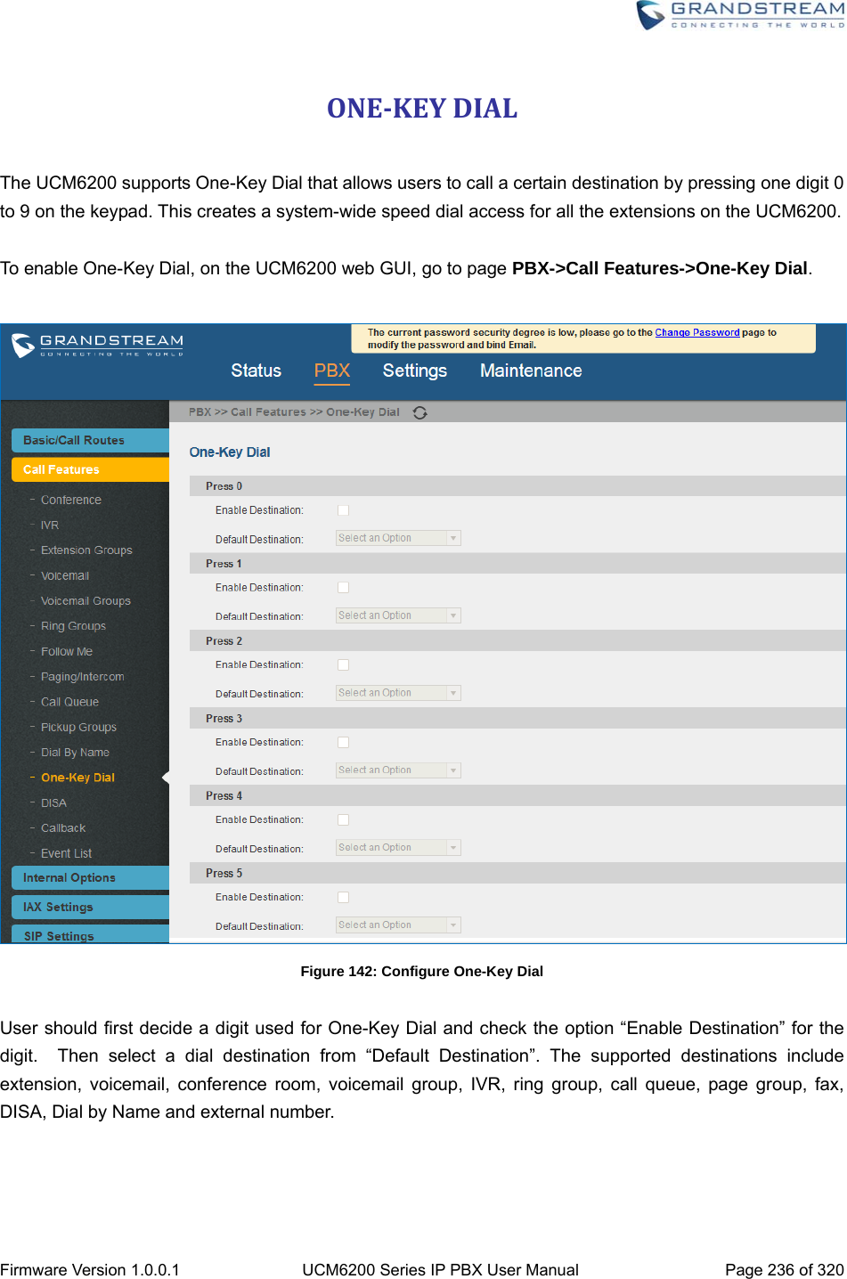
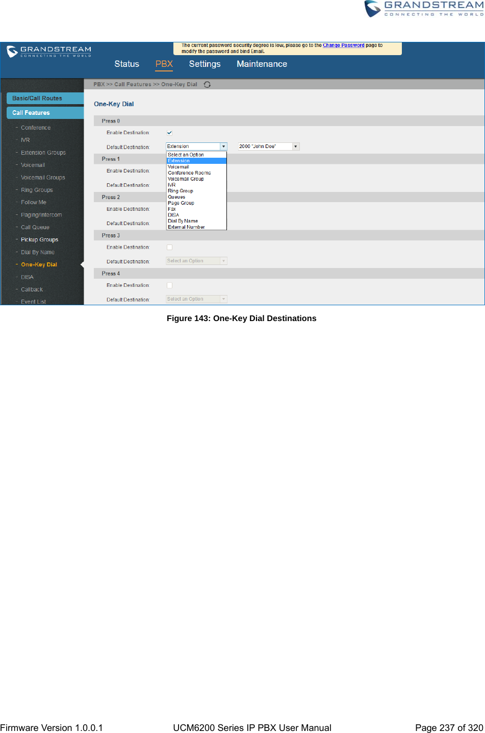
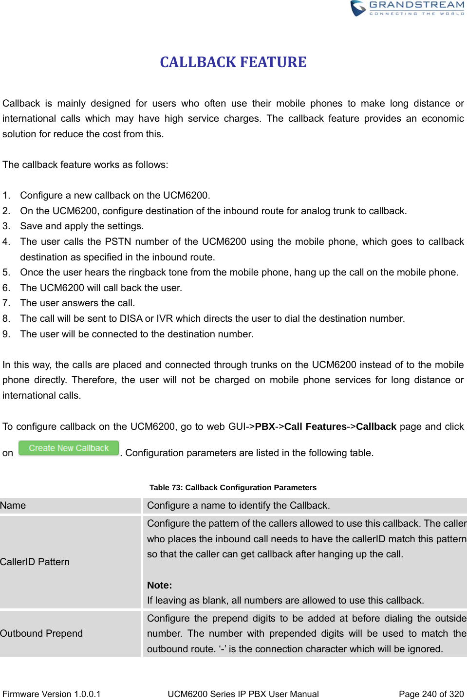
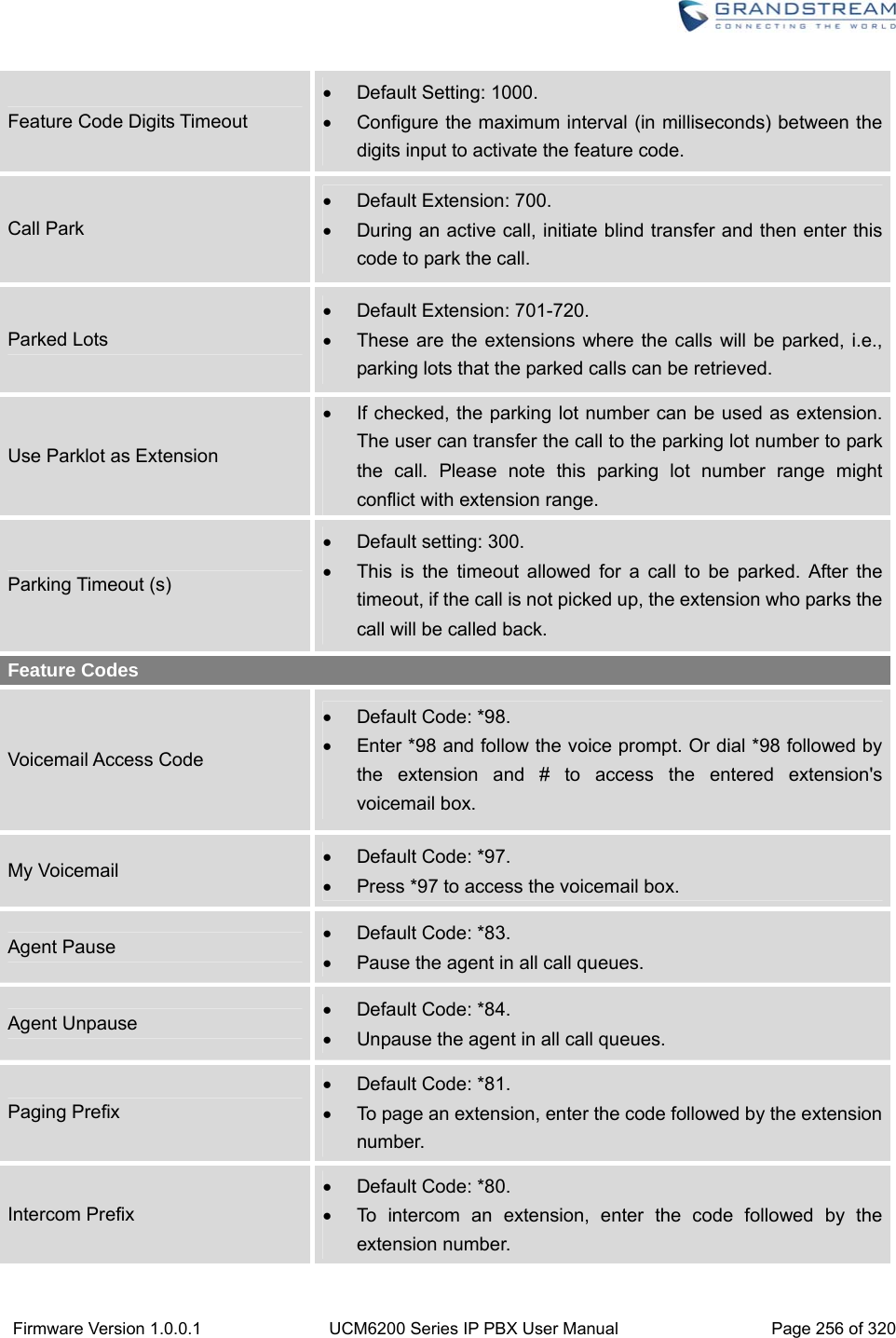
![Firmware Version 1.0.0.1 UCM6200 Series IP PBX User Manual Page 170 of 320 CALLROUTESOUTBOUNDROUTES In the UCM6200, an outgoing calling rule pairs an extension pattern with a trunk used to dial the pattern. This allows different patterns to be dialed through different trunks (e.g., "Local" 7-digit dials through a FXO while "Long distance" 10-digit dials through a low-cost SIP trunk). Users can also set up a failover trunk to be used when the primary trunk fails. Go to Web GUI->PBX->Basic/Call Routes->Outbound Routes to add and edit outbound rules. Click on "Create New Outbound Rule" to add a new outbound route. Click on to edit the outbound route. Click on to delete the outbound route. On the UCM6200, the outbound route priority is based on “Best matching pattern”. For example, the UCM6200 has outbound route A with pattern 1xxx and outbound route B with pattern 10xx configured. When dialing 1000 for outbound call, outbound route B will always be used first. This is because pattern 10xx is a better match than pattern 1xxx. Only when there are multiple outbound routes with the same pattern configured, users can click on to move the outbound route up/down to arrange the priority among those outbound routes. Table 56: Outbound Route Configuration Parameters Calling Rule Name Configure the name of the calling rule (e.g., local, long_distance, and etc). Letters, digits, _ and - are allowed. Pattern All patterns are prefixed with the "_". Special characters: X: Any Digit from 0-9. Z: Any Digit from 1-9. N: Any Digit from 2-9. ".": Wildcard. Match one or more characters. "!": Wildcard. Match zero or more characters immediately. Example: [12345-9] - Any digit from 1 to 9. Password Configure the password for users to use this rule when making outbound calls. Call Duration Limit Enable to configure the maximum duration for the call using this outbound route.](https://usermanual.wiki/Grandstream-Networks/UCM6208.Users-Manual-Part-Two/User-Guide-3044585-Page-1.png)
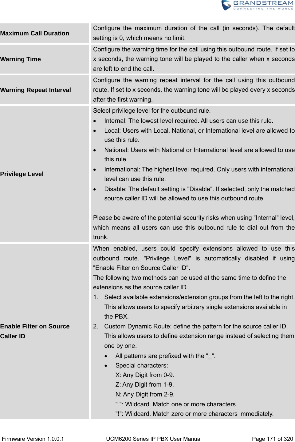
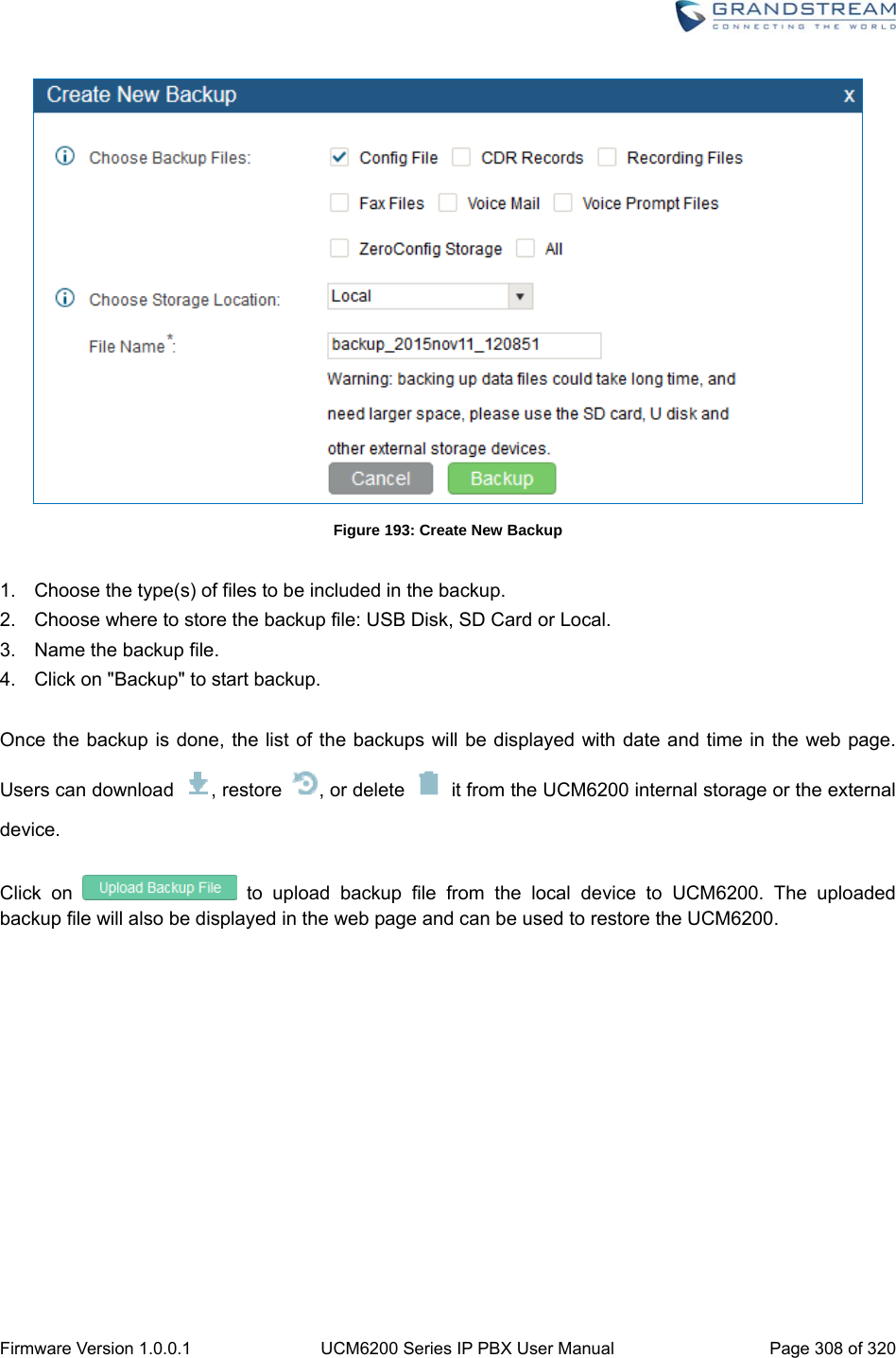
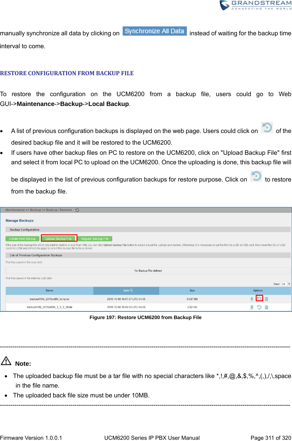
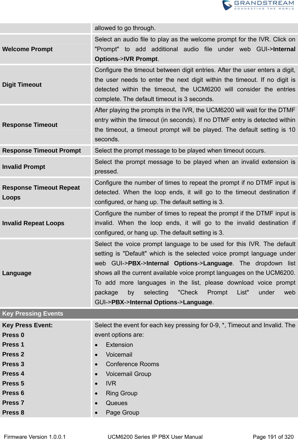
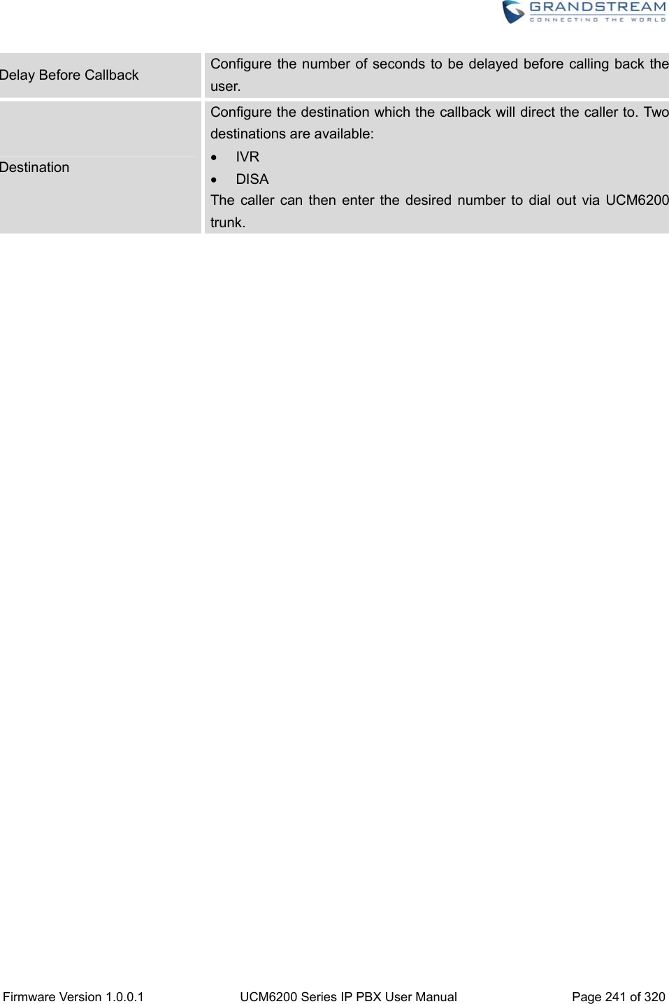
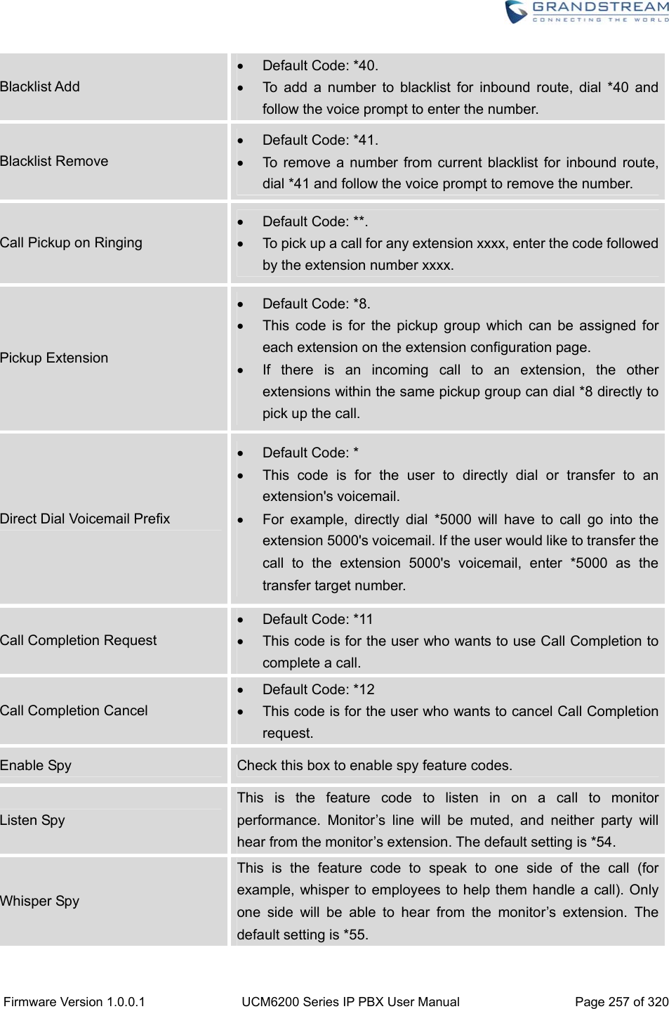
![Firmware Version 1.0.0.1 UCM6200 Series IP PBX User Manual Page 172 of 320 Example: [12345-9] - Any digit from 1 to 9. Send This Call Through Trunk Use Trunk Select the trunk for this outbound rule. Strip Allows the user to specify the number of digits that will be stripped from the beginning of the dialed string before the call is placed via the selected trunk. Example: The users will dial 9 as the first digit of a long distance calls. However, 9 should not be sent out via analog lines and the PSTN line. In this case, 1 digit should be stripped before the call is placed. Prepend Specify the digits to be prepended before the call is placed via the trunk. Those digits will be prepended after the dialing number is stripped. Use Failover Trunk Failover Trunk Failover trunks can be used to make sure that a call goes through an alternate route, when the primary trunk is busy or down. If "Use Failover Trunk" is enabled and "Failover trunk" is defined, the calls that cannot be placed via the regular trunk may have a secondary trunk to go through. Example: The user's primary trunk is a VoIP trunk and the user would like to use the PSTN when the VoIP trunk is not available. The PSTN trunk can be configured as the failover trunk of the VoIP trunk. Strip Allows the user to specify the number of digits that will be stripped from the beginning of the dialed string before the call is placed via the selected trunk. Example: The users will dial 9 as the first digit of a long distance calls. However, 9 should not be sent out via analog lines and the PSTN line. In this case, 1 digit should be stripped before the call is placed. Prepend Specify the digits to be prepended before the call is placed via the trunk. Those digits will be prepended after the dialing number is stripped. INBOUNDROUTES Inbound routes can be configured via Web GUI->PBX->Basic/Call Routes->Inbound Routes. Click on "Create New Inbound Rule" to add a new inbound route. Click on "Blacklist" to configure blacklist for all inbound routes. Click on to edit the inbound route.](https://usermanual.wiki/Grandstream-Networks/UCM6208.Users-Manual-Part-Two/User-Guide-3044585-Page-3.png)
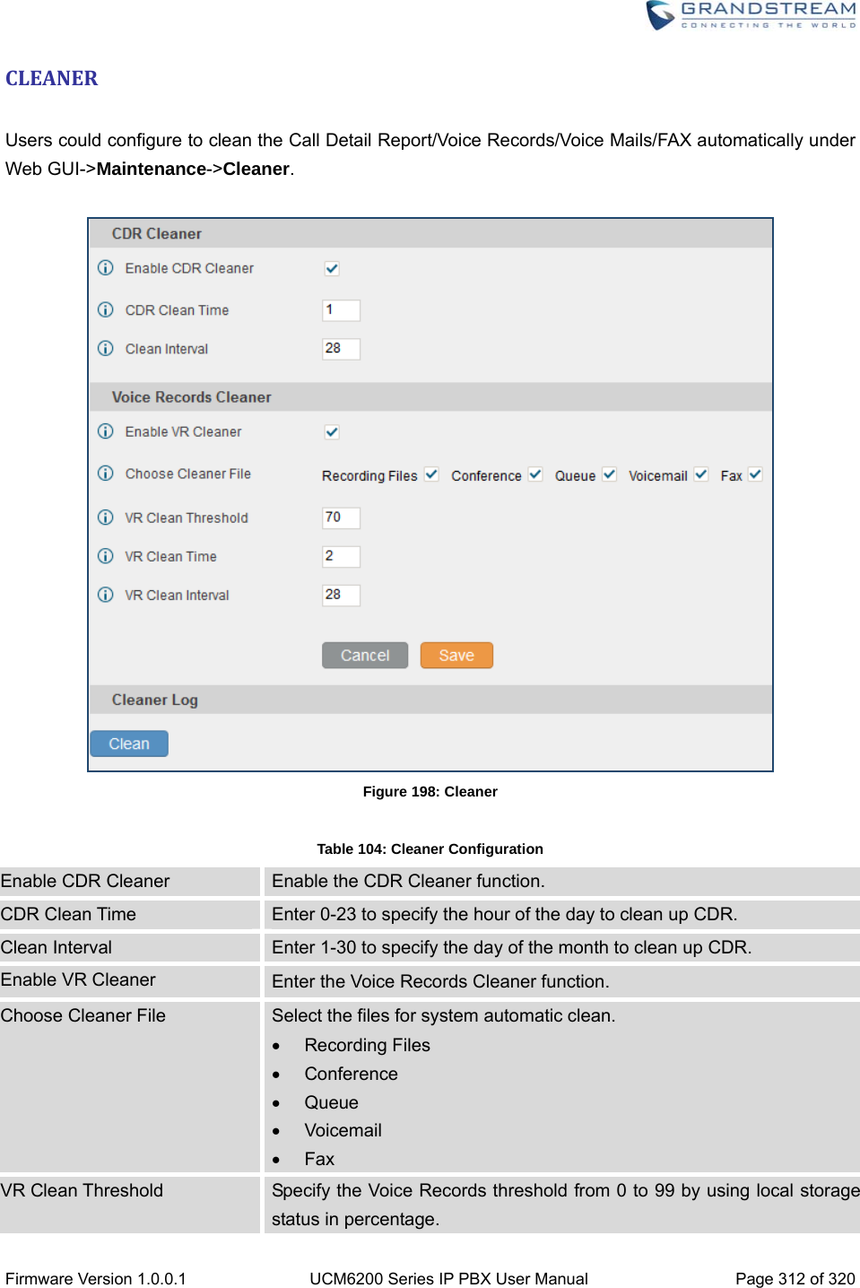
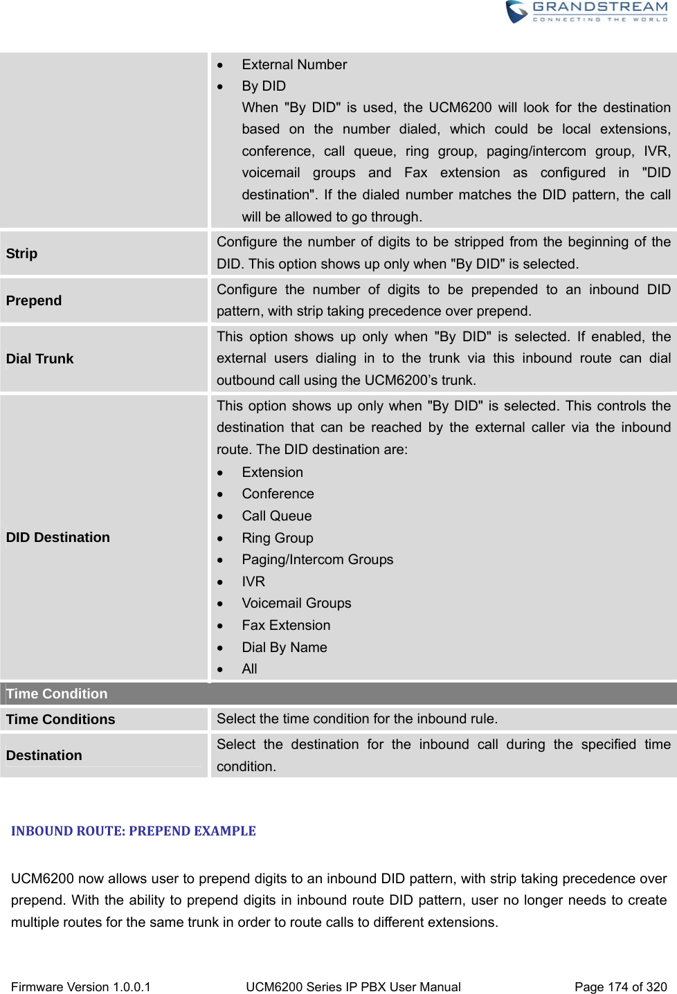
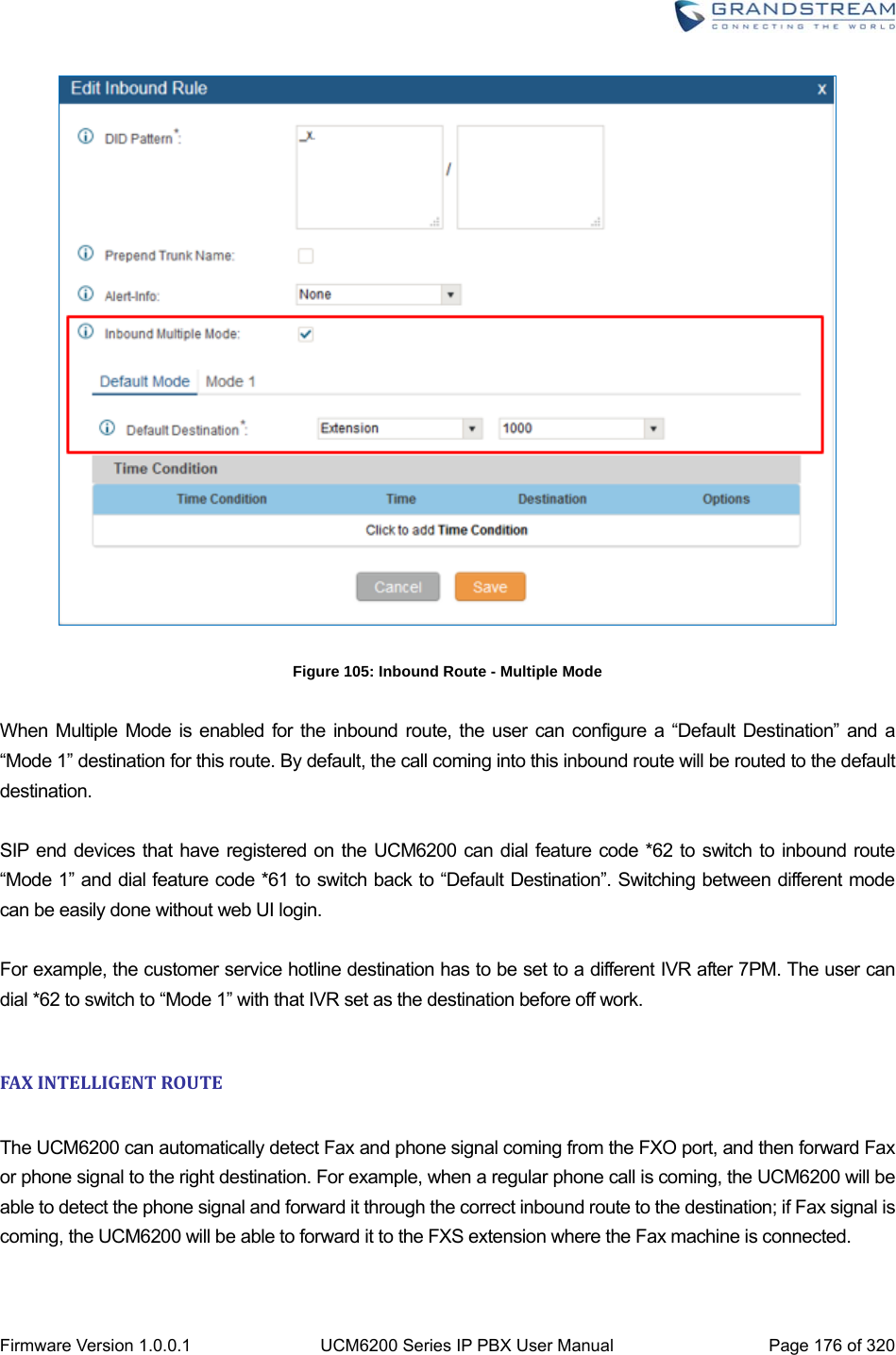
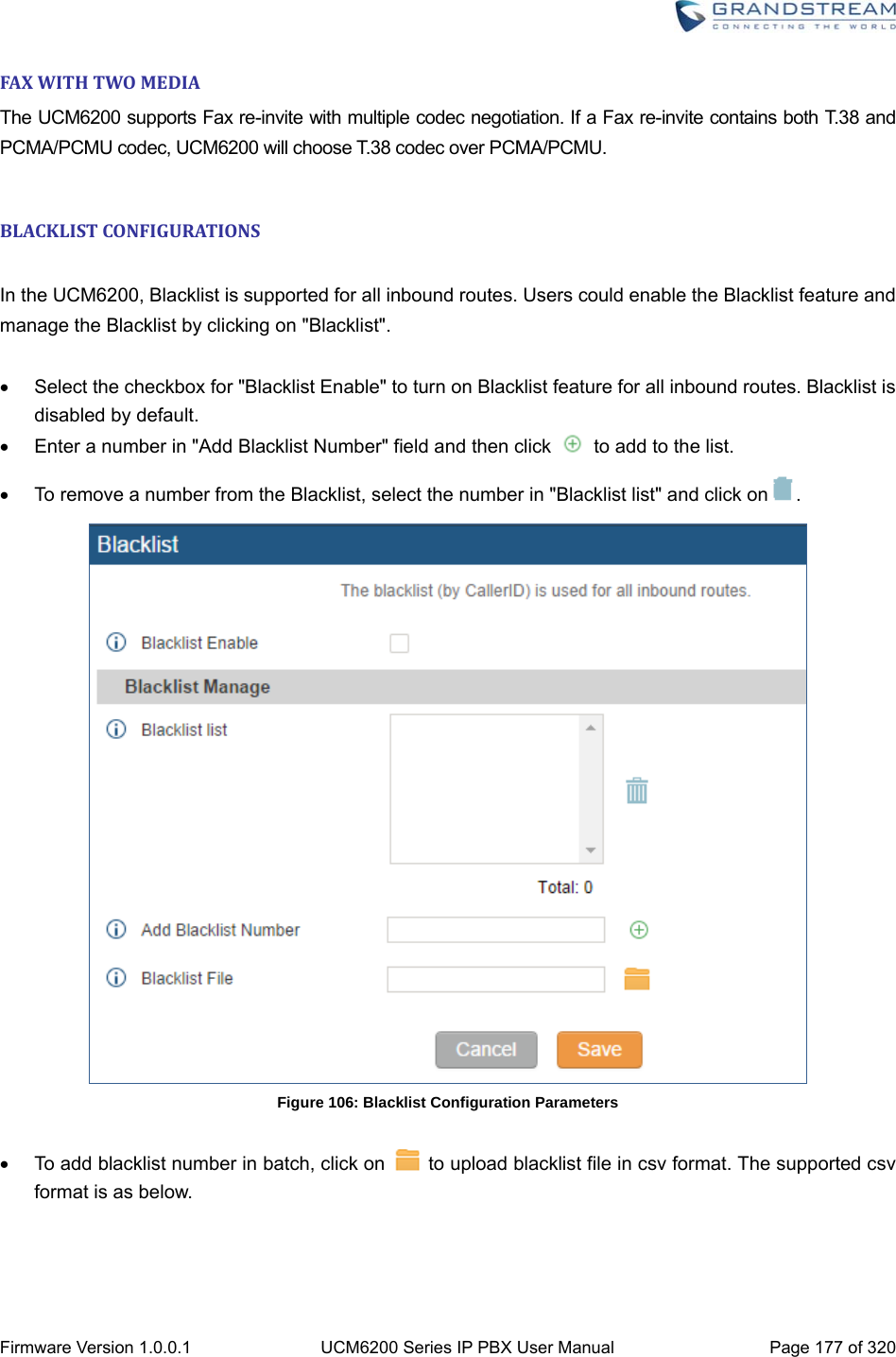
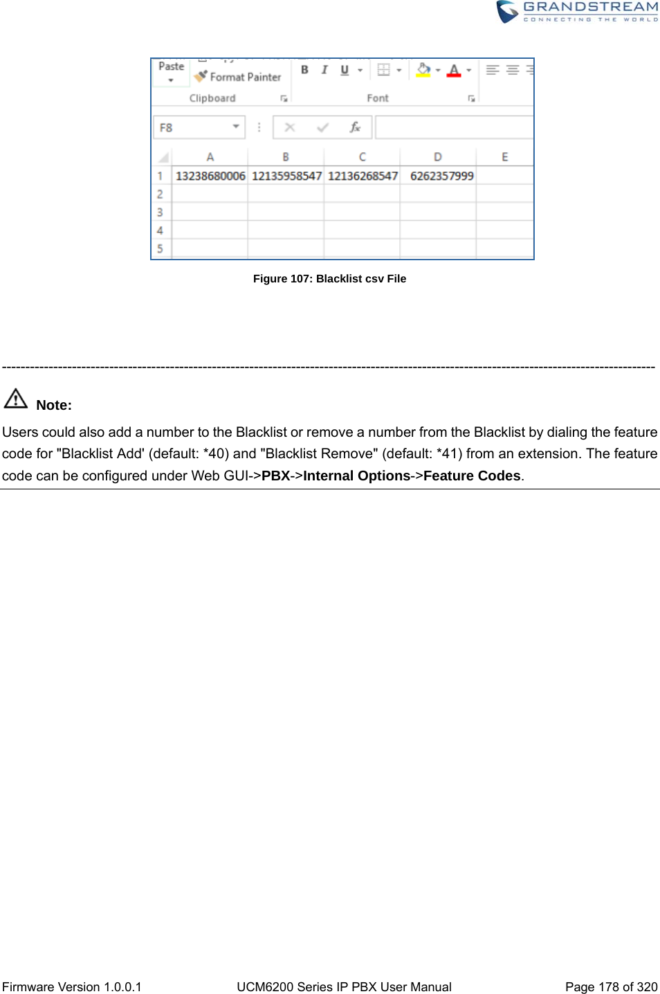
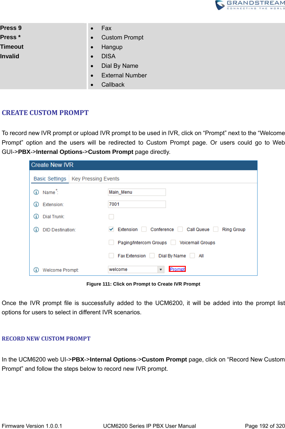
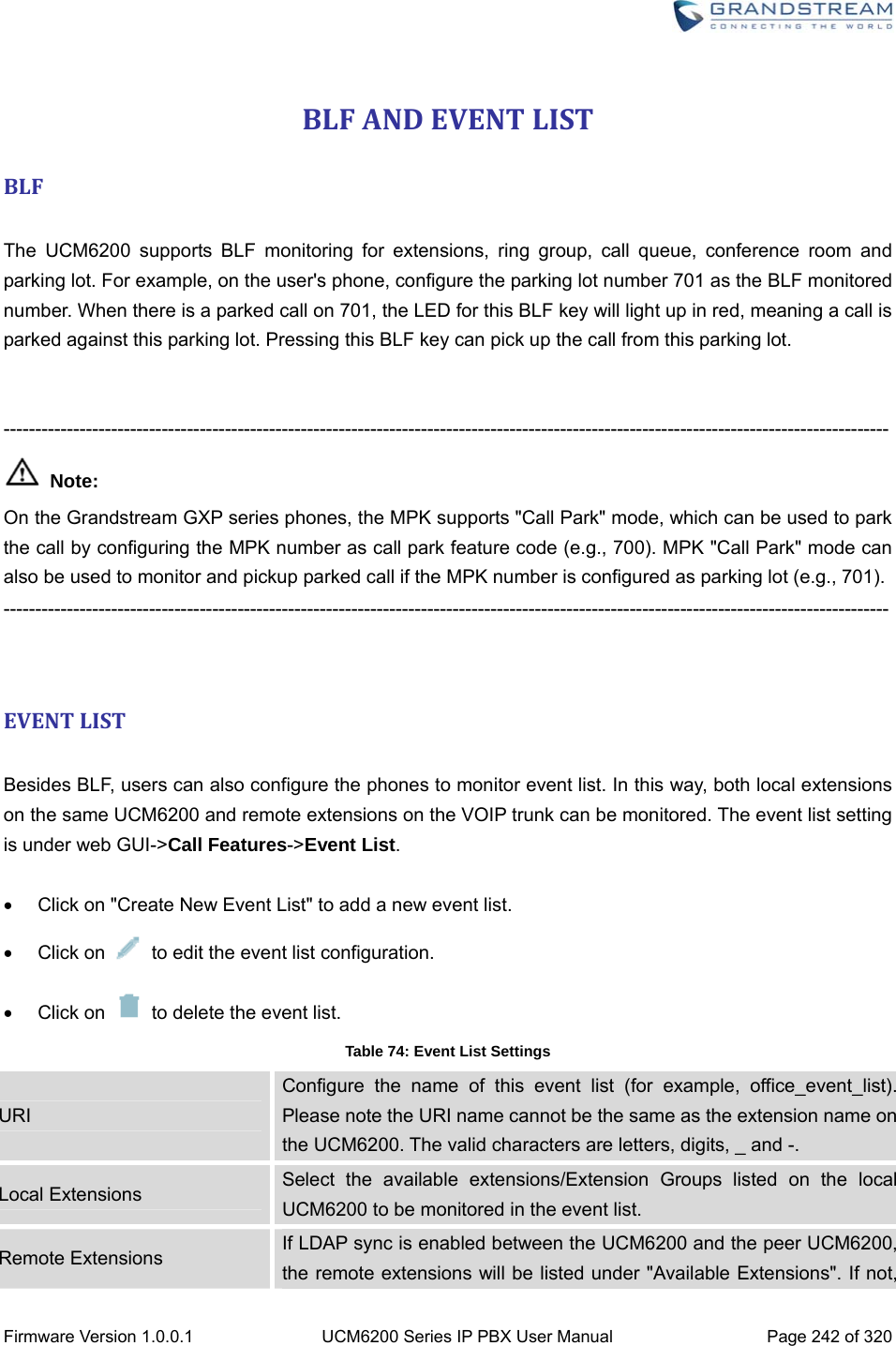
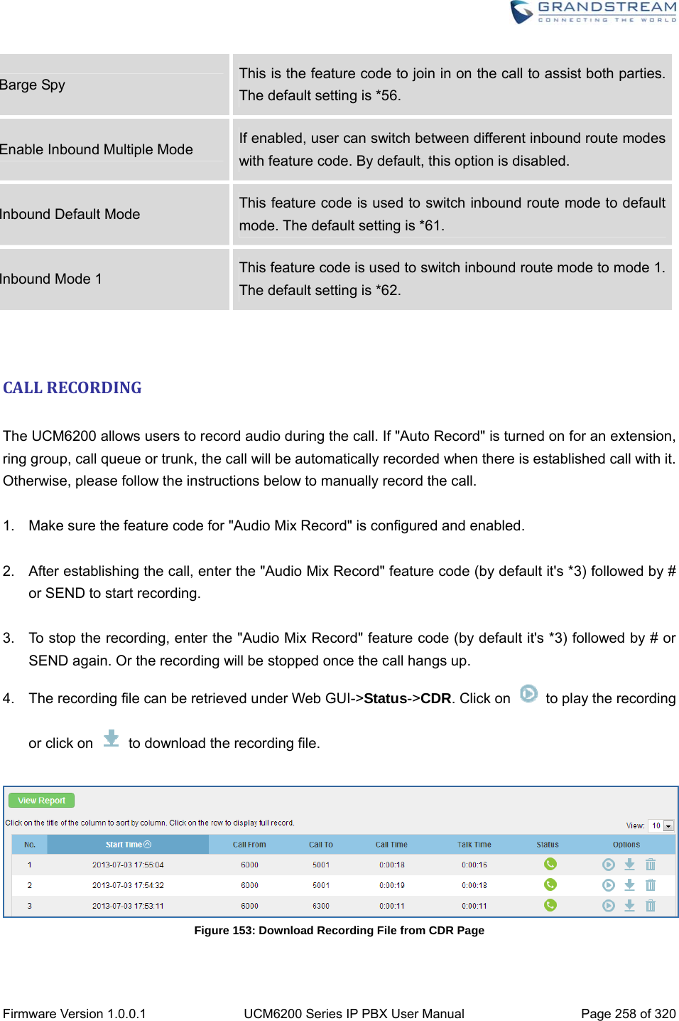
![Firmware Version 1.0.0.1 UCM6200 Series IP PBX User Manual Page 173 of 320 Click on to delete the inbound route. INBOUNDRULECONFIGURATIONSTable 57: Inbound Rule Configuration Parameters Trunks Select the trunk to configure the inbound rule. DID Pattern All patterns are prefixed with the "_". Special characters: X: Any Digit from 0-9. Z: Any Digit from 1-9. N: Any Digit from 2-9. ".": Wildcard. Match one or more characters. "!": Wildcard. Match zero or more characters immediately. Example: [12345-9] - Any digit from 1 to 9. The pattern can be composed of two parts, divided by a ‘/’ character. The first part is used to specify the dialed number the second part is used to specify the caller ID and it is optional, if set it means only the extension with the specific caller ID is allowed to call in or call out. For example, patter '_2XXX/1234' means the only extension with the caller ID '1234' is allowed to use this rule. Prepend Trunk Name Prepend trunk name to display Alert-Info Configure the Alert-Info, when UCM6200 receives an INVITE request, the Alert-Info header field specifies an alternative ring tone to the UAS. Inbound Multiple Mode Multiple mode allows user to switch between destinations of the inbound rule by feature codes. Configure related feature codes in the “Feature Codes” page. If this option is enabled, user can use feature code to switch between different destinations. Default Destination Select the default destination for the inbound call. Extension Voicemail Conference Room Queue Ring Group Paging/Intercom Voicemail Group Fax DISA IVR Dial By Name](https://usermanual.wiki/Grandstream-Networks/UCM6208.Users-Manual-Part-Two/User-Guide-3044585-Page-4.png)
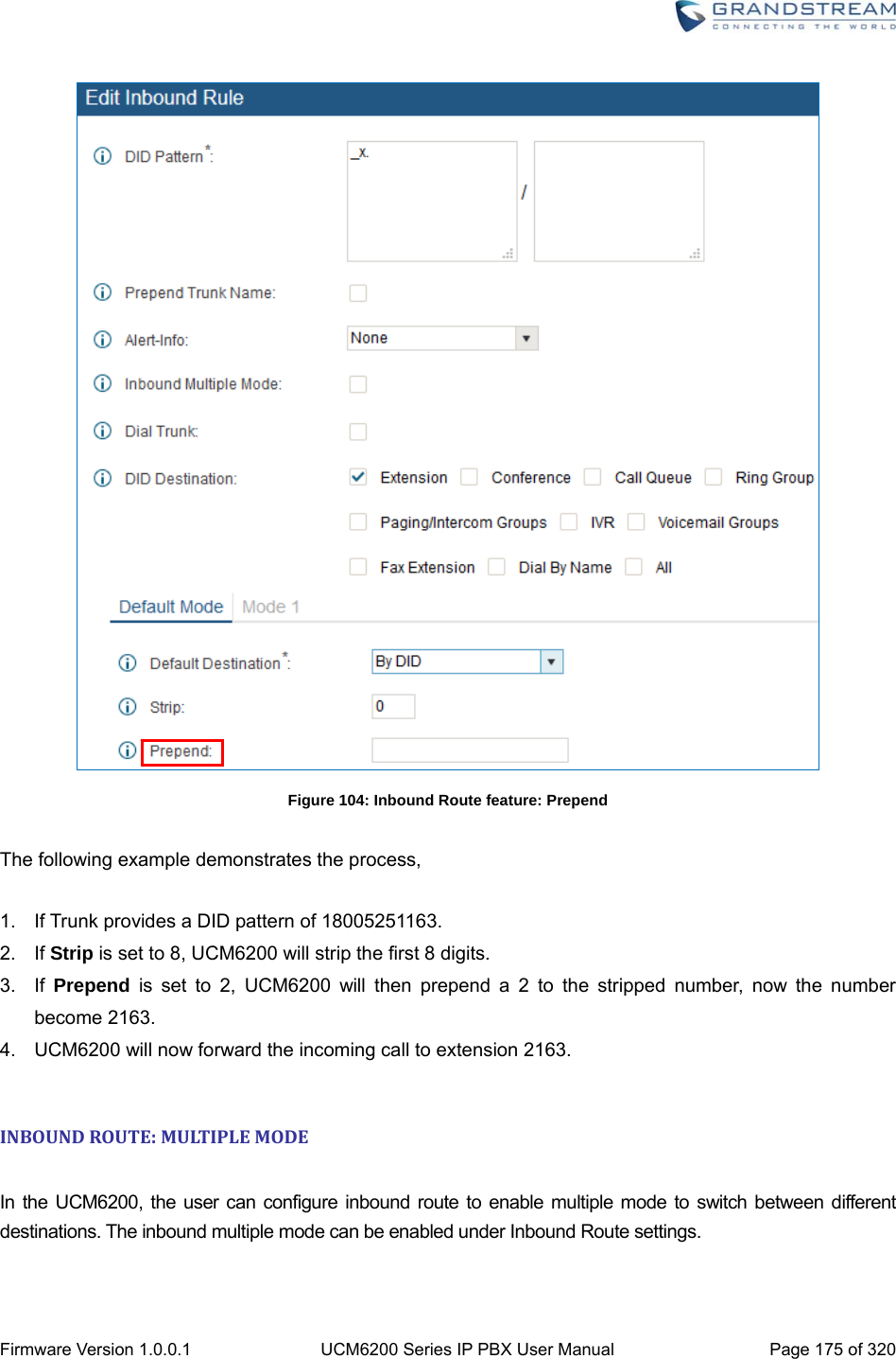

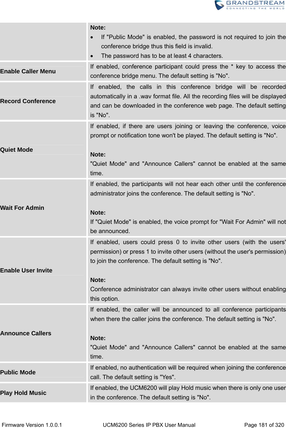
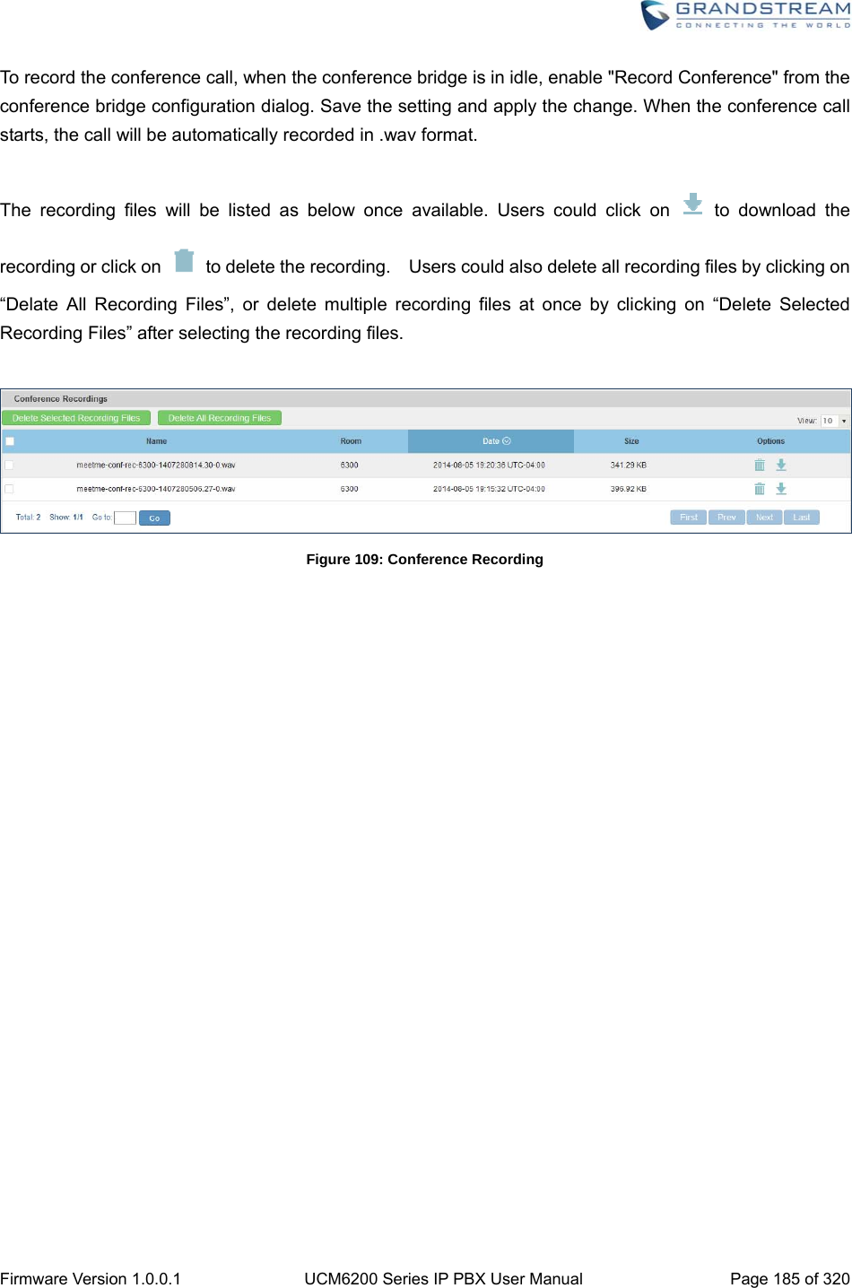
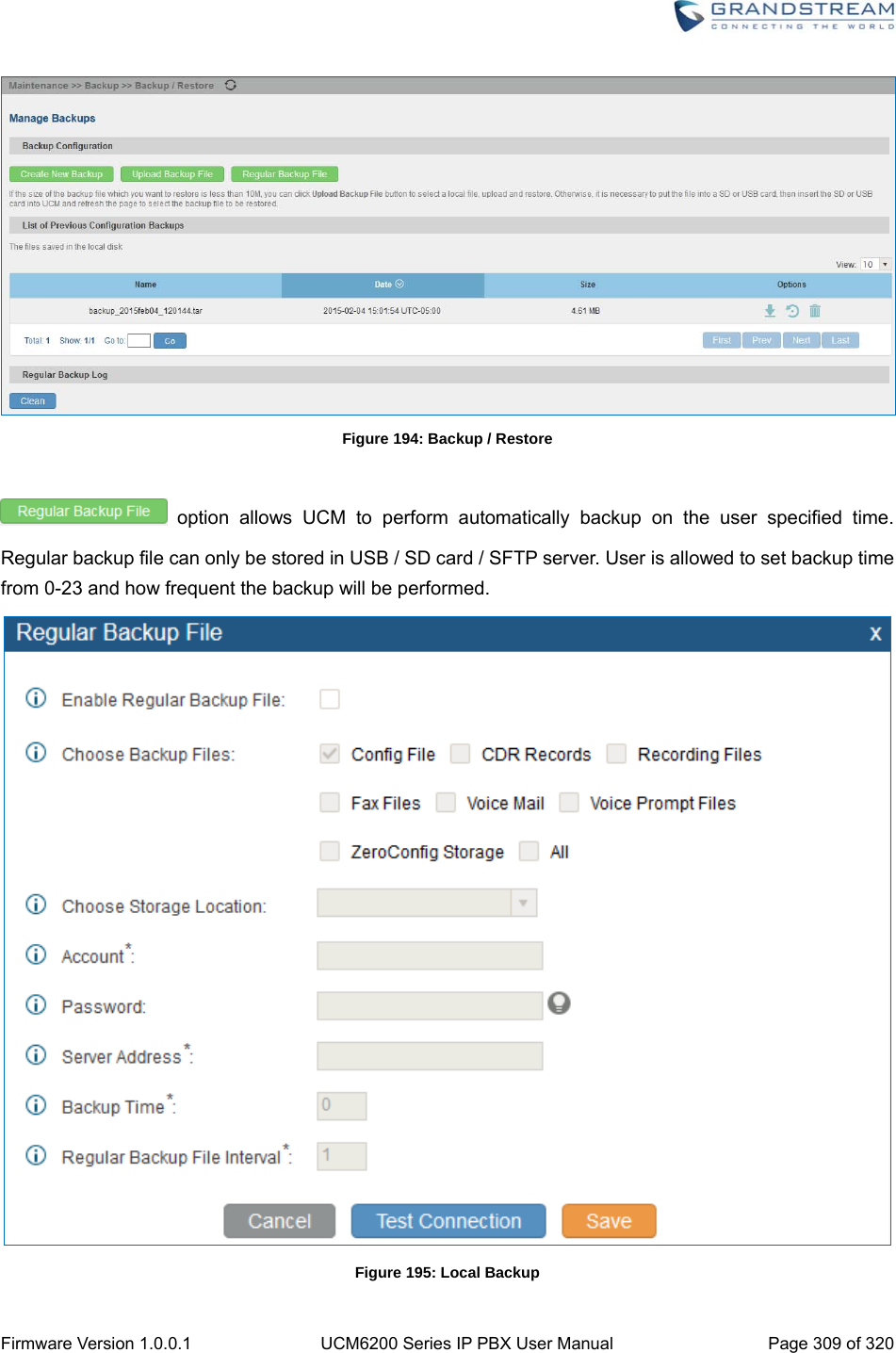
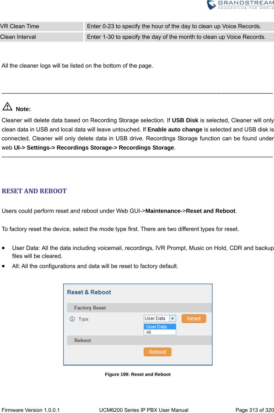
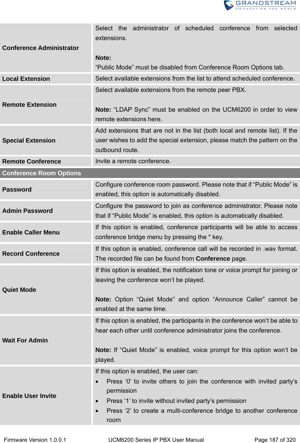
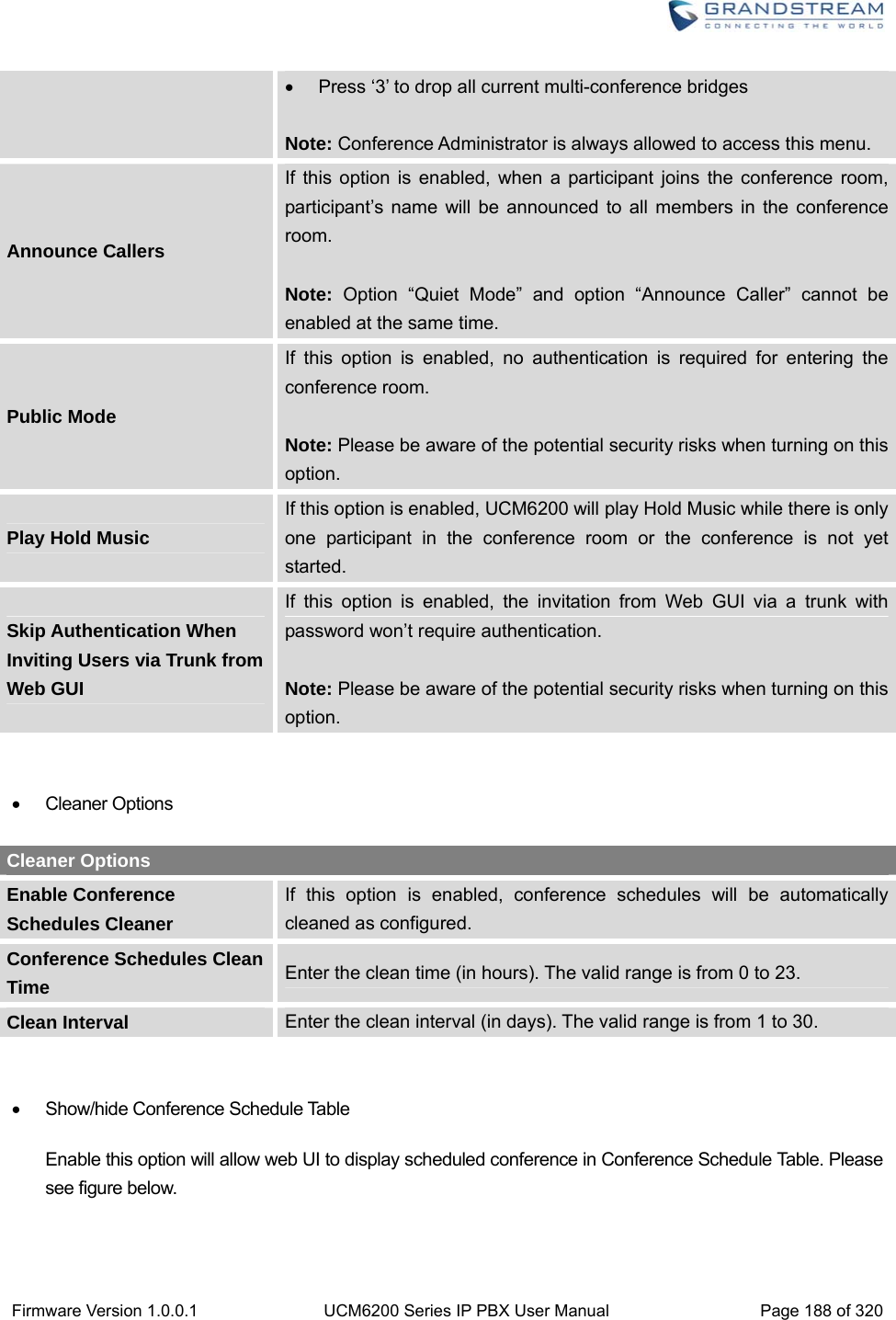
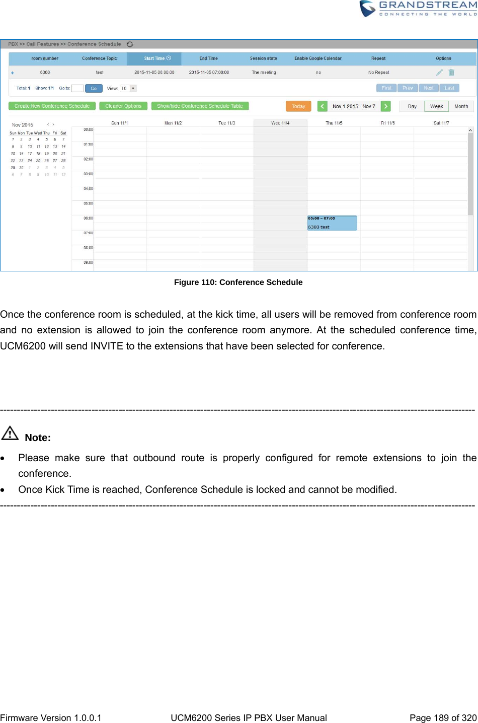
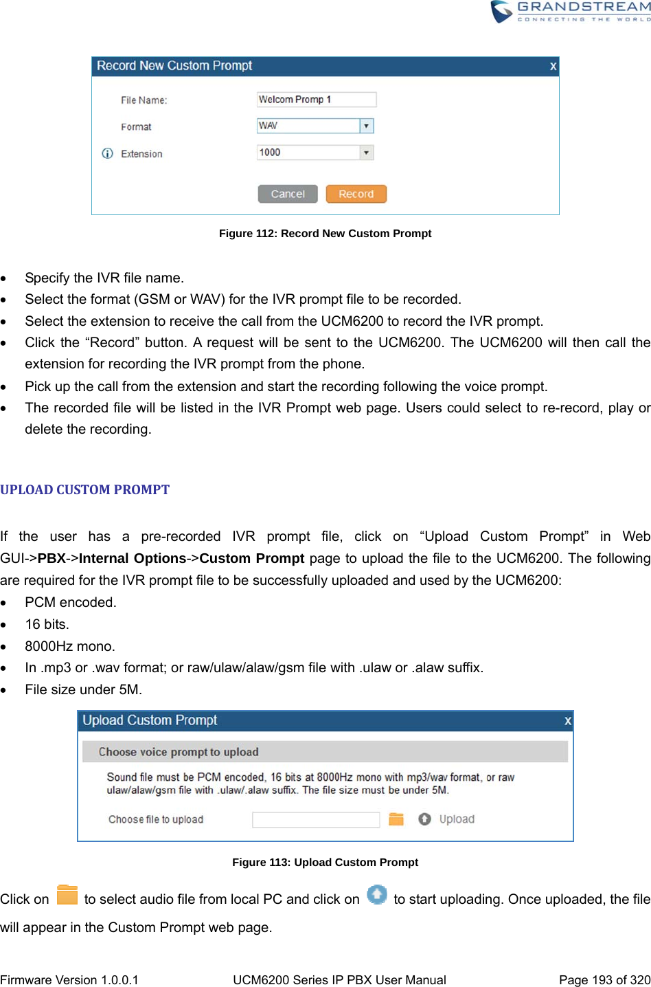
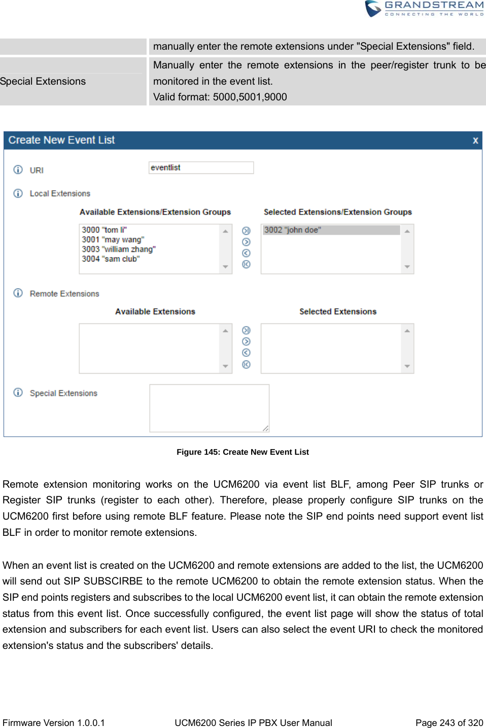
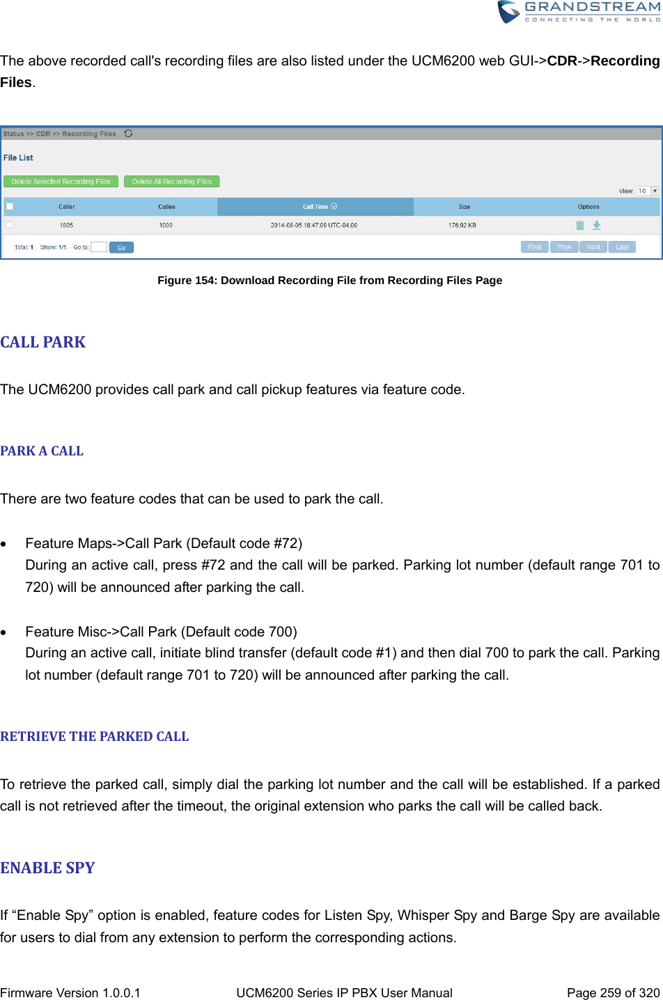
![Firmware Version 1.0.0.1 UCM6200 Series IP PBX User Manual Page 186 of 320 CONFERENCESCHEDULECONFERENCESCHEUDLECONFIGURATION Conference Schedule can be found under UCM6200 web UI->PBX->Call Features->Conference Schedule. Users can create, edit, view and delete a Conference Schedule. Click on “Create New Conference Schedule” to add a new Conference Schedule. Click on the scheduled conference to edit or delete the event. After the user configures UCM6200 with Google Service Settings [GOOGLE SERVICE SETTINGS SUPPORT] and enables Google Calendar for Conference Schedule, the conference schedule on the UCM6200 can be synchronized with Google Calendar for authorized Google account. Table 60: Conference Schedule Parameters Schedule Options Conference Topic Configure the name of the scheduled conference. Letters, digits, _ and - are allowed. Conference Room Select a conference room for this scheduled conference. Kick Time(m) Set kick time before conference starts. When kick time is reached, a warning prompt will be played for all attendees in the conference room. After 5 minutes, this conference room will be cleared and locked for the scheduled conference to begin. Note: Kick Time cannot be less than 6 minutes in order to clear the conference room. Description The description of scheduled conference. Repeat Repeat interval of scheduled conference. By default it’s set to single event. Schedule Time Configure the beginning date and duration of scheduled conference. Note: Please pay attention to avoid time conflict on schedules in the same conference room. Enable Google Calendar Select this option to sync scheduled conference with Google Calendar. Note: Google Service Setting OAuth2.0 must be configured on the UCM6200. Please refer to section [GOOGLE SERVICE SETTINGS SUPPORT].](https://usermanual.wiki/Grandstream-Networks/UCM6208.Users-Manual-Part-Two/User-Guide-3044585-Page-17.png)


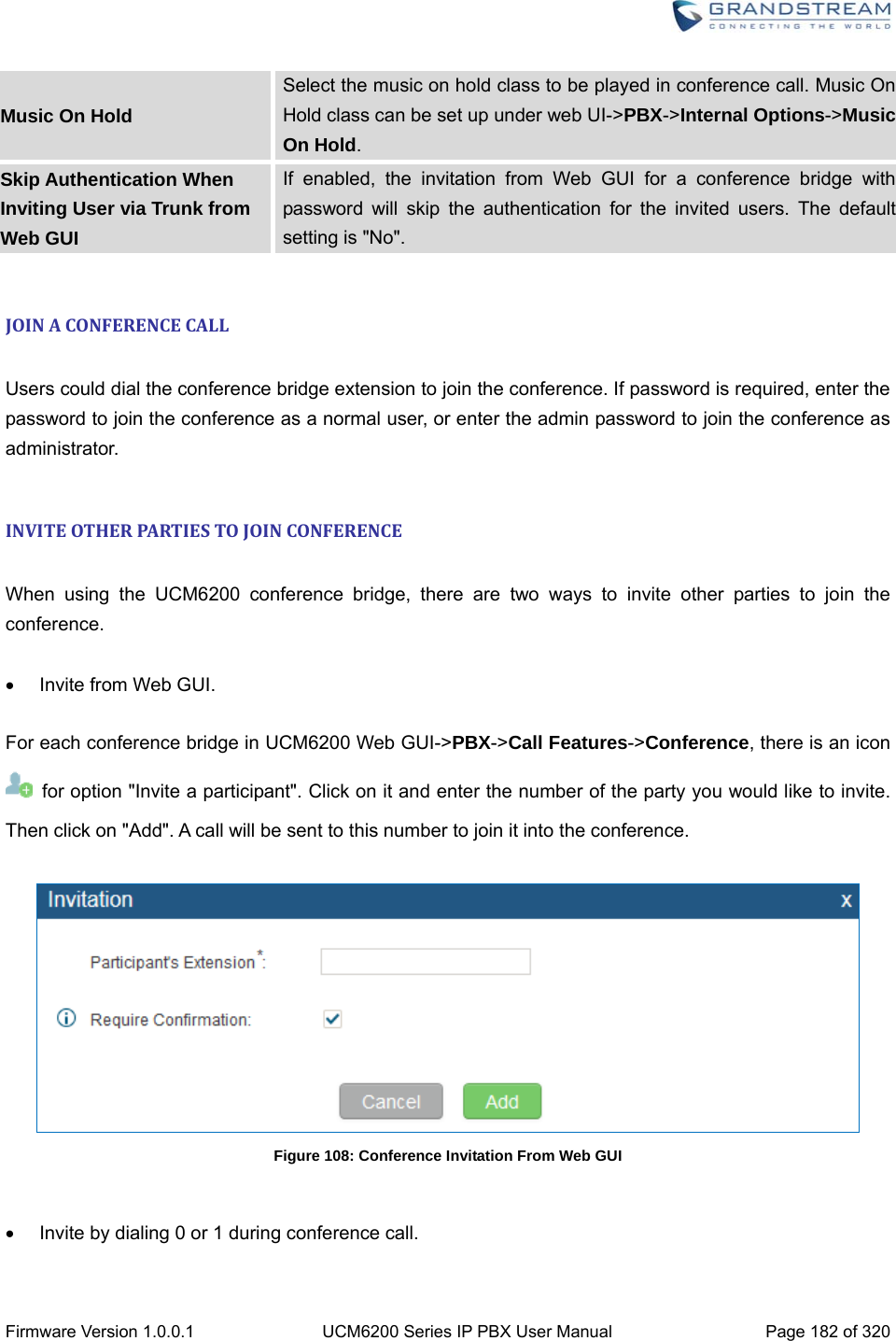
![Firmware Version 1.0.0.1 UCM6200 Series IP PBX User Manual Page 252 of 320 4. Enable or disable “Require Confirmation” option. If enabled, the confirmation of the invited monitor’s extension is required before the active call can be monitored. This option can be used to avoid adding participant who has auto-answer configured or call forwarded to voicemail. 5. Click on “Add”. An INVITE will be sent to the monitor’s extension. The monitor can answer the call and start monitoring. If “Require Confirmation” is enabled, the user will be asked to confirm to monitor the call. Another way to monitor active calls is to dial the corresponding feature codes from an extension. Please refer to [Table 75: UCM6200 Feature Codes] and [ENABLE SPY] section for instructions.](https://usermanual.wiki/Grandstream-Networks/UCM6208.Users-Manual-Part-Two/User-Guide-3044585-Page-83.png)


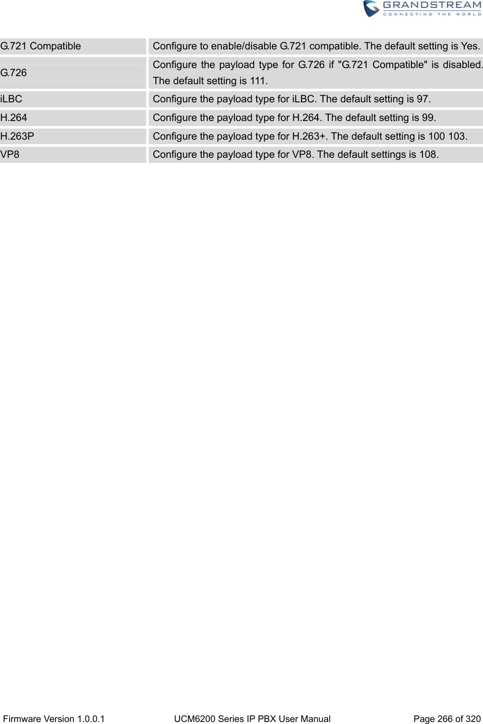
![Firmware Version 1.0.0.1 UCM6200 Series IP PBX User Manual Page 265 of 320 INTERNALOPTIONS/RTPSETTINGS Table 78: Internal Options/RTP Settings RTP Start Configure the RTP port starting number. The default setting is 10000. RTP End Configure the RTP port ending address. The default setting is 20000. Strict RTP Configure to enable or disable strict RTP protection. If enabled, RTP packets that do not come from the source of the RTP stream will be dropped. The default setting is "Disable". RTP Checksums Configure to enable or disable RTP Checksums on RTP traffic. The default setting is "Disable". ICE Support Configure whether to support ICE. The default setting is enabled. ICE is the integrated use of STUN and TURN structure to provide reliable VoIP or video calls and media transmission, via a SIP request/ response model or multiple candidate endpoints exchanging IP addresses and ports, such as private addresses and TURN server address. STUN Server Configure STUN server address. STUN protocol is a Client/Server and also a Request/Response protocol. It’s used to check the connectivity between the two terminals, such as maintaining a NAT binding entries keep-alive agreement. The default STUN Server is stun.ipvideotalk.com. Valid format: [(hostname | IP-address) [':' port] The default port number is 3478 if not specified. INTERNALOPTIONS/PAYLOAD The UCM6200 payload type for audio codecs and video codes can be configured here. Table 79: Internal Options/Payload AAL2-G.726 Configure payload type for ADPCM (G.726, 32kbps, AAL2 codeword packing). The default setting is 112. DTMF Configured payload type for DTMF. The default setting is 101.](https://usermanual.wiki/Grandstream-Networks/UCM6208.Users-Manual-Part-Two/User-Guide-3044585-Page-96.png)


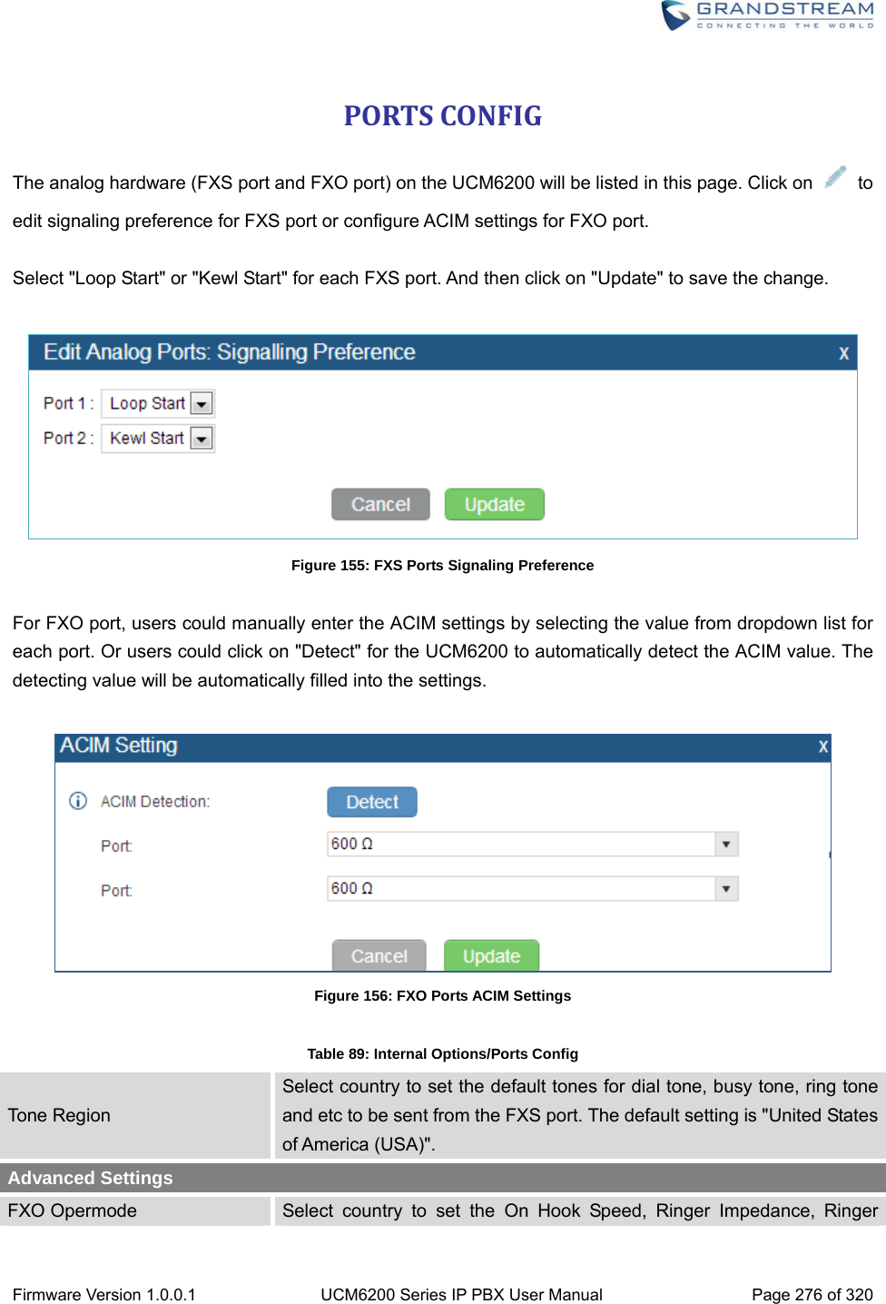
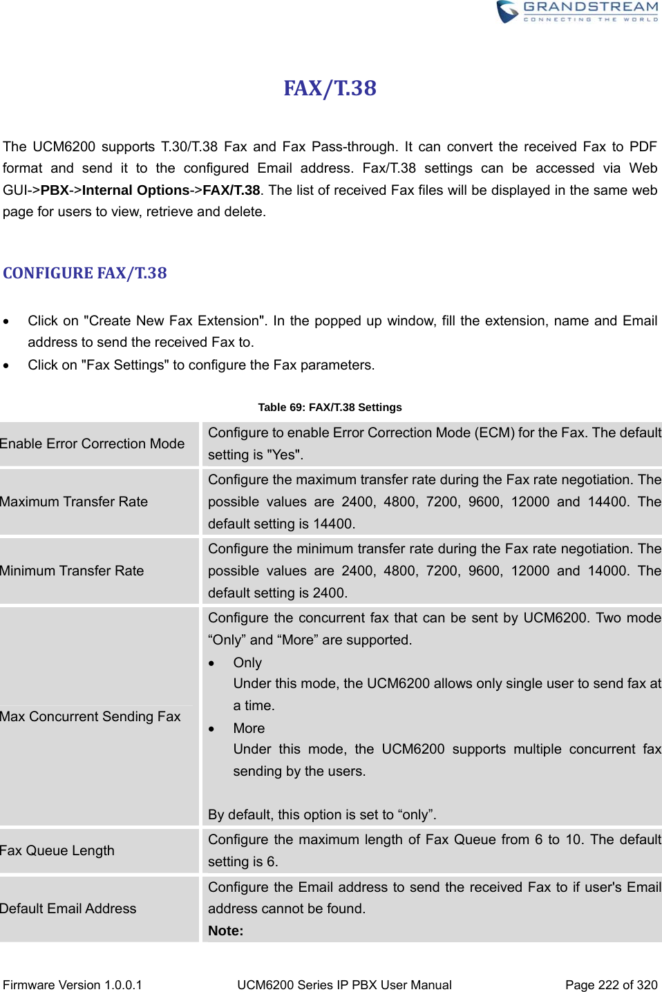
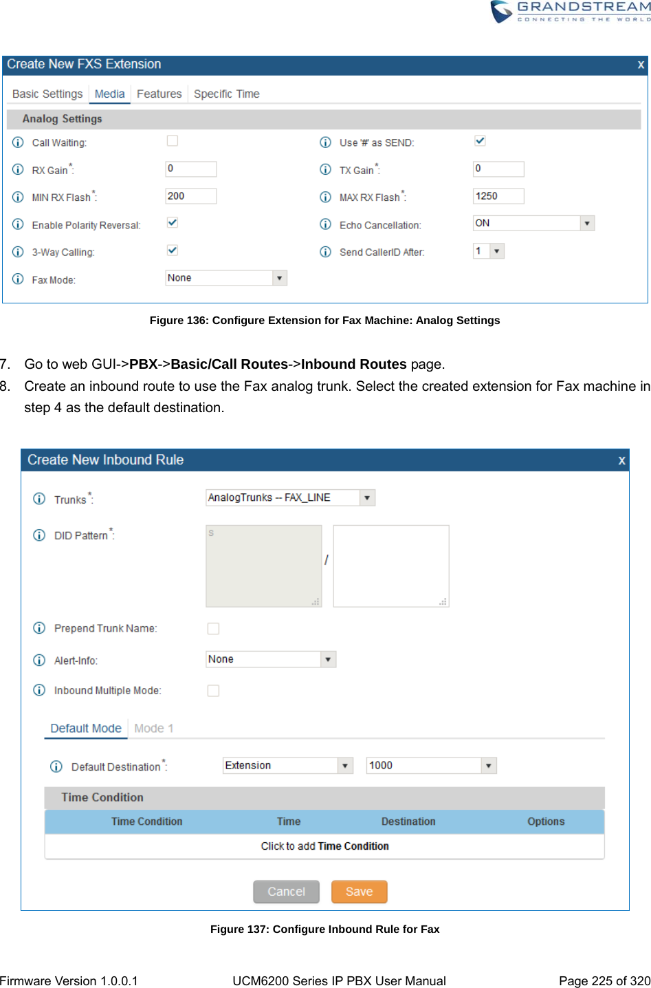
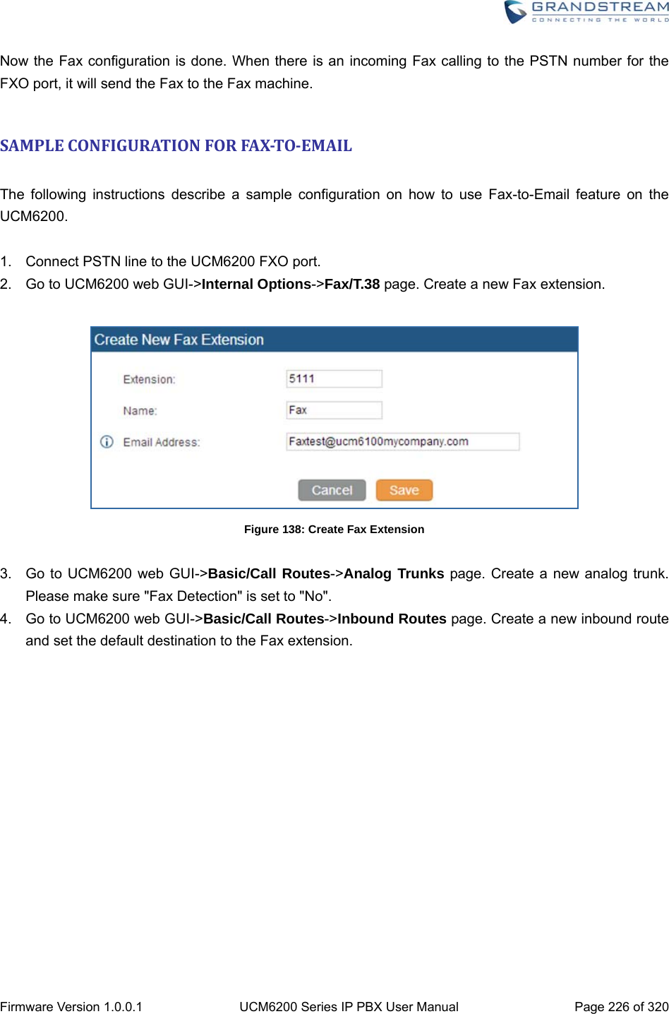
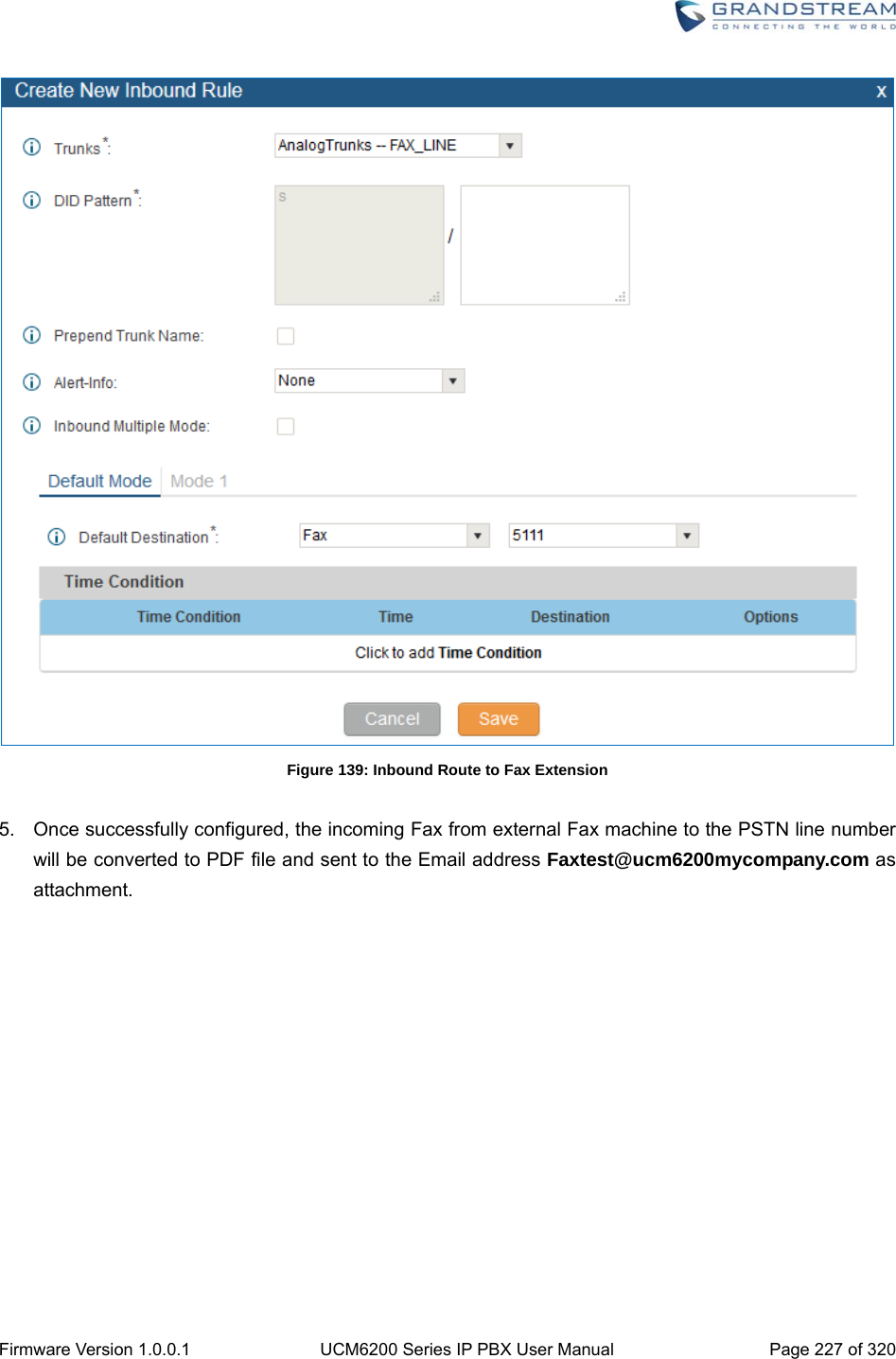
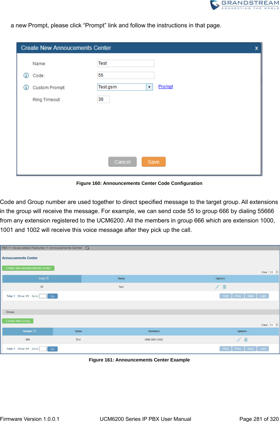
![Firmware Version 1.0.0.1 UCM6200 Series IP PBX User Manual Page 278 of 320 VALUE‐ADDEDFEATURESFAXSENDING The UCM6200 supports sending Fax via web UI access. This feature can be found on web UI->PBX->Value-added Features->Fax Sending page. In order to send fax, pre-setup for analog trunk and outbound route is required. Please refer to [ANALOG TRUNKS], [VOIP TRUNKS] and [OUTBOUND ROUTES] sections for configuring analog trunk and outbound route. After making sure analog trunk or VoIP Trunk is setup properly and UCM6200 can reach out to PSTN numbers via the trunk, on Fax Sending page, enter the fax number and upload the file to be faxed. Then click on “Send” to start. The progress of sending fax will be displayed in web UI. Users can also view the sending history is in the same web page. Figure 157: Fax Sending in Web UI ANNOUNCEMENTSCENTER The UCM6200 supports Announcements Center feature which allows users to pre-record and store voice message into UCM6200 with a specified code. The users can also create group with specified extensions. When the code and the group number are dialed together in the combination of code + group number, the specified voice message is sent to all group members and only extensions in the group will hear the voice message.](https://usermanual.wiki/Grandstream-Networks/UCM6208.Users-Manual-Part-Two/User-Guide-3044585-Page-109.png)
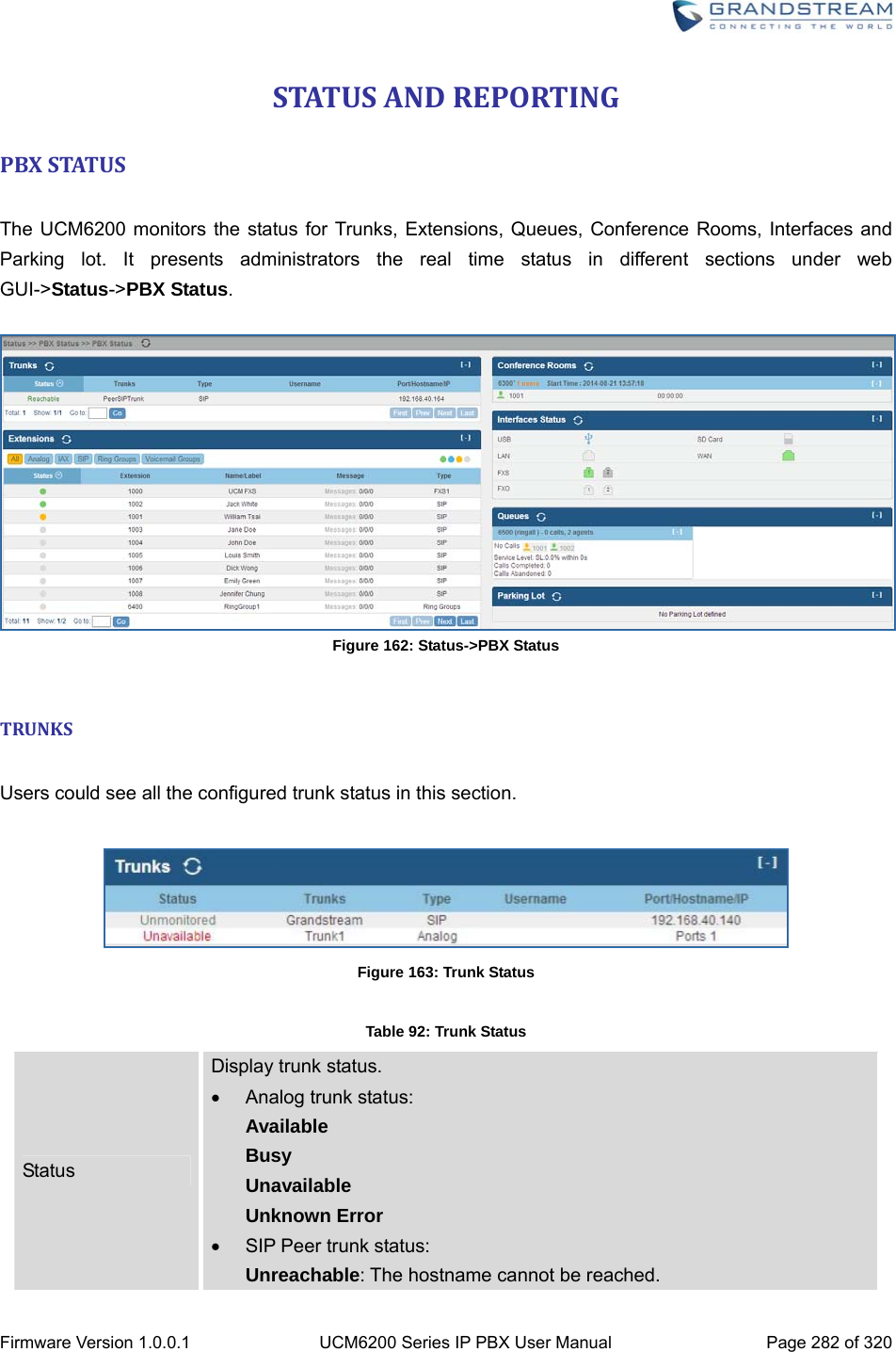
![Firmware Version 1.0.0.1 UCM6200 Series IP PBX User Manual Page 283 of 320 Unmonitored: QUALIFY feature is not turned on to be monitored. Reachable: The hostname can be reached. SIP Register trunk status: Registered Unrecognized Trunk Trunks Display trunk name Type Display trunk Type: Analog SIP IAX Username Display username for this trunk. Port/Hostname/IP Display Port for analog trunk, or Hostname/IP for VoIP (SIP/IAX) trunk. Other operations are also available in trunk status section: Click on "Trunks", the web page will redirect to trunk configuration page which can also be accessed via web GUI->PBX->Basic/Call Routes->Analog Trunks. Click on to refresh the trunk status. Click on [ + ] to expand the status detail table. Click on [ - ] to hide the status detail table. EXTENSIONS Users could see all the configured extension status in this section. Figure 164: Extension Status](https://usermanual.wiki/Grandstream-Networks/UCM6208.Users-Manual-Part-Two/User-Guide-3044585-Page-114.png)
![Firmware Version 1.0.0.1 UCM6200 Series IP PBX User Manual Page 284 of 320 Table 93: Extension Status Status Display extension number (including feature code). The color indicator has the following definitions. Green: Free Blue: Ringing Yellow: In Use Grey: Unavailable Extension Display the extension number. Name/Label First name and last name of the extension. Message Display message status for the extension. Example: 2/4/1 Description: There are 2 urgent messages, 4 messages in total and 1 message that has been already read. Type Displays extension type. SIP User IAX User Analog User Ring Groups Voicemail Groups Other operations are also available in extension status section: Click on "Extensions", the web page will redirect to extension configuration page which can also be accessed via web GUI->PBX->Basic/Call Routes->Extensions. Click on to refresh the extension status. Click on one of the tabs to display the corresponding extensions accordingly. Click on [ + ] to expand the status detail table. Click on [ - ] to hide the status detail table. QUEUES Users could see all the configured call queue status in this section. The following figure shows the call queue 6500 being in used.](https://usermanual.wiki/Grandstream-Networks/UCM6208.Users-Manual-Part-Two/User-Guide-3044585-Page-115.png)
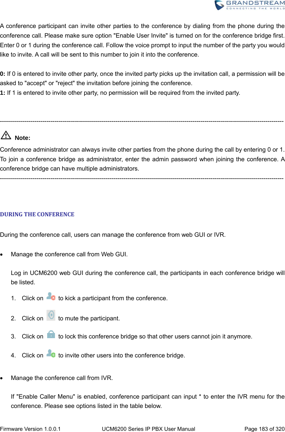
![Firmware Version 1.0.0.1 UCM6200 Series IP PBX User Manual Page 285 of 320 Figure 165: Queue Status The current call status (caller ID, duration), agent status, service level, calls summary (completed/abandoned) are shown for the call queue. The agent status is defined as below. Table 94: Agent Status The agent is available/idle. The agent is ringing. The agent is talking/busy. The agent has been logged out. On the UCM6200, Service Level is defined as the percentage of high-quality calls over all calls in the call queue, where high-quality call means calls answered within 10 seconds. Other operations are also available in queue status section: Click on "Queues", the web page will redirect to call queue configuration page which can also be accessed via web GUI->PBX->Call Features->Call Queue. Click on to refresh the call queue status. Click on [ + ] to expand the call queue detail. Click on [ - ] to hide the call queue detail. CONFERENCEROOMS Users could see all the conference room status in this section. It shows all the configured conference rooms, current users, call duration for each user and conference call.](https://usermanual.wiki/Grandstream-Networks/UCM6208.Users-Manual-Part-Two/User-Guide-3044585-Page-116.png)
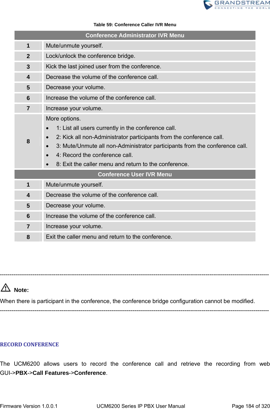
![Firmware Version 1.0.0.1 UCM6200 Series IP PBX User Manual Page 286 of 320 Figure 166: Conference Room Status Other operations are also available in conference room status section: Click on "Conference Rooms", the web page will redirect to conference room configuration page which can also be accessed via web GUI->PBX->Call Features->Conference. Click on to refresh the conference room status. Click on [ + ] to expand the conference room details. Click on [ - ] to hide the conference room details. INTERFACESSTATUS This section displays interface/port connection status on the UCM6200. The following example shows the interface status for UCM6204 with USB, WAN port, FXS1, FXS2 and FXO1 connected. Figure 167: UCM6204 Interfaces Status Table 95: Interface Status Indicators USB connected. USB disconnected. SD Card connected. SD Card disconnected.](https://usermanual.wiki/Grandstream-Networks/UCM6208.Users-Manual-Part-Two/User-Guide-3044585-Page-117.png)
![Firmware Version 1.0.0.1 UCM6200 Series IP PBX User Manual Page 287 of 320 LAN/WAN connected. LAN/WAN not configured. LAN/WAN disconnected. FXS/FXO connected. FXS/FXO waiting. FXS/FXO busy. FXS/FXO not configured. FXS/FXO disconnected. Other operations are also available in interface status section: Click on "Interfaces Status", the web page will redirect to ports configuration page which can also be accessed via web GUI->PBX->Internal Options->Ports Config. Click on to refresh the interface status. Click on [ + ] to expand the interface details. Click on [ - ] to hide the interface details. PARKINGLOT The UCM6200 supports call park using feature code. When there is call being parked, this section will display the parking lot status. Figure 168: Parking Lot Status Table 96: Parking Lot Status Caller ID Display the caller ID who parks the call. Channel Display channel for the call park. Extension Display the parking lot number where the call is parked/retrieved. Timeout Display timeout (in seconds) for the parked call. The status page will dynamically update this timer from 120 seconds (default) to 0. When the timer](https://usermanual.wiki/Grandstream-Networks/UCM6208.Users-Manual-Part-Two/User-Guide-3044585-Page-118.png)
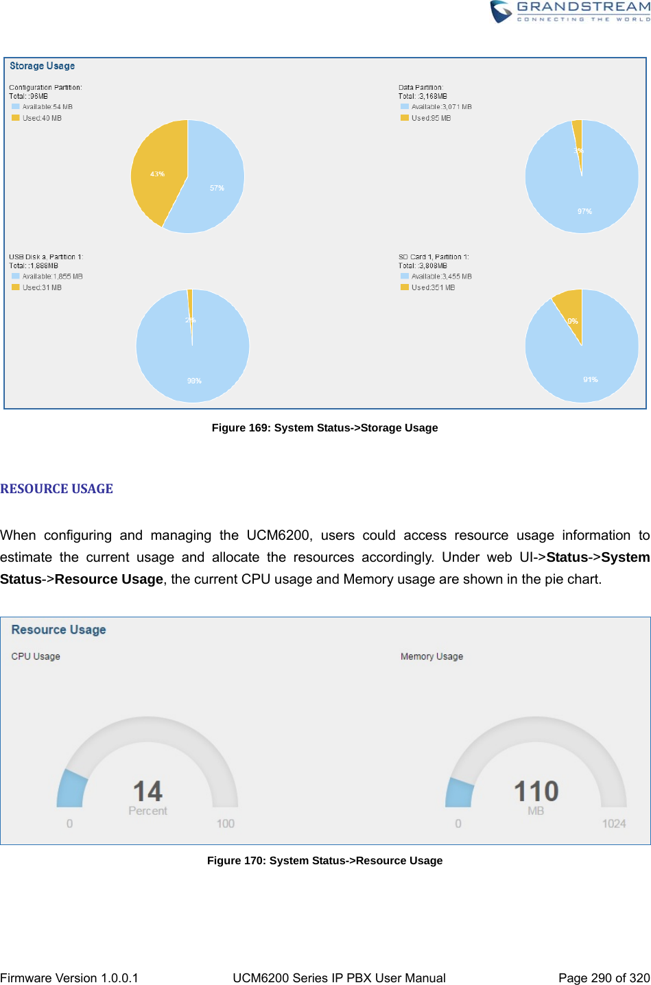
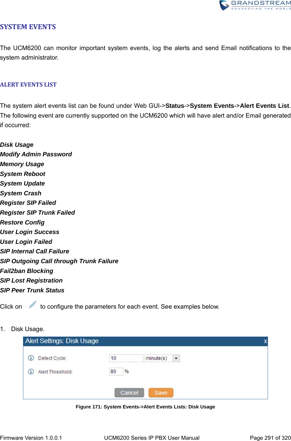
![Firmware Version 1.0.0.1 UCM6200 Series IP PBX User Manual Page 288 of 320 reaches 0, the caller who parks the call will be called back. Other operations are also available in parking lot status section: Click on "Parking Lot", the web page will redirect to feature codes page which can also be accessed via web GUI->PBX->Internal Options->Feature Codes. Click on to refresh the parking lot status. Click on [ + ] to expand the parking lot details. Click on [ - ] to hide the parking details. SYSTEMSTATUS The UCM6200 system status can be accessed via Web GUI->Status->System Status, which displays the following system information. General Network Storage Usage Resource Usage GENERAL Under Web GUI->Status->System Status->General, users could check the hardware and software information for the UCM6200. Please see details in the following table. Table 97: System Status->General Status ->System Status -> General Model Product model. Part Number Product part number. System Time Current system time. The current system time is also available on the upper right of each web page. Up Time System up time since the last reboot. Boot Boot version. Core Core version. Base Base version. Program Program version. This is the main software release version.](https://usermanual.wiki/Grandstream-Networks/UCM6208.Users-Manual-Part-Two/User-Guide-3044585-Page-119.png)