Graupner and KG MC-32 ComputerSystem Graupner HoTT User Manual 33124 mx20 HoTT 1 EN indd
Graupner GmbH & Co. KG ComputerSystem Graupner HoTT 33124 mx20 HoTT 1 EN indd
Users Manual
Programming Manual
33124.mc-32 HoTT.1.en
HOPPING TELEMETRY TRANSMISSION
mc-32
2Table of contents
Transmitter initialization ...............................................38
Firmware update ................................................... 39
Receiver initialization ................................................... 42
Firmware update ................................................... 43
Installation notices ....................................................... 46
Receiver system power supply ..............................47
Term defi nitions ........................................................... 50
Switch and control assignments .................................. 52
Digital trimming ............................................................ 54
Winged models ............................................................ 56
Receiver layout ...................................................... 57
Helicopter models ........................................................ 58
Receiver layout ...................................................... 59
Program descriptions
Loading a new memory location .................................. 60
"Model select" ............................................................ 63
"Copy / Erase" ............................................................64
Erase model .......................................................... 64
Copy model ¼ model ........................................... 64
Export to SD card .................................................. 65
Import from SD card .............................................. 66
Copy fl
ight phase ................................................... 66
"Suppress menus" ..................................................... 67
"Suppress models" .................................................... 67
"Base setup model"
Winged model ....................................................... 68
Model name .................................................... 68
Stick mode ...................................................... 68
Bound receiver ................................................68
Binding receivers ............................................ 69
Receiver output ...............................................70
RF transmit ...................................................... 71
Range test ....................................................... 71
DSC output...................................................... 72
General notices
Table of contents ........................................................... 2
Environmental protection notices .................................. 3
Safety notices ................................................................ 4
Safety notices and handling regulations
for nickel-metal-hydride rechargeable batteries ............. 8
Foreword ......................................................................10
Remote control set description .................................... 11
Recommended chargers ............................................. 13
Transmitter power supply ............................................. 14
Receiver power supply .......................................... 16
Joystick length adjustment...........................................17
Opening the transmitter housing ................................. 17
Changing joystick behavior .......................................... 18
Transmitter description ................................................ 20
Operating elements ............................................... 20
Backside of the transmitter .................................... 21
Headset connector ................................................ 21
Mini-USB connector .............................................. 21
Data jack ............................................................... 21
DSC (Direct Servo Control) ................................... 22
Data storage / card slot ......................................... 22
Display and keypad ............................................... 24
Operating the "data terminal" ................................ 25
Shortcuts ............................................................... 26
Hidden menu columns ........................................... 27
Hidden mode ......................................................... 28
Language selection and display contrast .............. 28
Joystick calibration ................................................ 29
Telemetry data display ...........................................32
Displayed warnings ............................................... 36
Function fi eld displays ........................................... 37
Position display for rotary controls, CTRL 7 & 8 .... 37
Entry lockout .......................................................... 37
Table of contents
Cut-off ............................................................. 72
Helicopter model ................................................... 74
Model name .................................................... 74
Stick mode ...................................................... 74
Bound receiver ................................................74
Binding receivers ............................................ 75
Receiver output ...............................................76
RF transmit ...................................................... 77
Range test ....................................................... 77
DSC output...................................................... 78
Autorotation .....................................................78
Auto.C1 Pos. .................................................... 79
Cut-off ............................................................. 79
"Model type" ............................................................... 82
"Helicopter type" ........................................................ 86
"Servo adjustment" ....................................................90
"Stick mode"
Winged model ....................................................... 92
Helicopter model ................................................... 94
"Control adjust"
Winged model ....................................................... 96
Helicopter model ................................................. 100
Throttle limit function ...................................... 104
Idle setting ...................................................... 105
Throttle limit in combination with AR in the
"Stick mode" menu ...................................... 107
"Dual Rate / Expo"
Winged model ..................................................... 108
Helicopter model ................................................. 112
"Channel 1 curve"
Winged model ..................................................... 116
Helicopter model ................................................. 119
"Switch display" .......................................................122
"Control switch" ....................................................... 123
How do I program a fl ight phase? .............................. 126
3
Table of contents
"Phase settings"
Winged model ..................................................... 128
Helicopter model ................................................. 132
"Phase assignment" ................................................ 134
"Phase trim" (winged model) .................................... 136
"Non-delayed channels" .......................................... 137
"Timers (general)" .................................................... 138
"Flight phase timers" ............................................... 142
What is a mixer? ........................................................ 145
"Wing mixers" ...........................................................146
"Helicopter mixer" ....................................................164
Adjusting the throttle and pitch curve .................. 175
Autorotation setting ............................................. 178
General remarks about freely progr. Mixers .............. 180
"Free mixers" ............................................................181
Linear mixers ...................................... beginning 185
Curve mixer ........................................ beginning 187
Examples............................................................. 190
"MIX active/phase" ................................................... 192
"Mix Only Channel" ..................................................193
"Dual mixer" .............................................................. 194
"Swashplate mixer" ..................................................196
"Fail-safe" .................................................................196
"Teacher / pupil" ....................................................... 198
Connection schematic ......................................... 201
Wireless HoTT system ........................................ 202
"Tx. output swap" .....................................................206
"Telemetry" ...............................................................208
Setting& Data View .............................................. 209
Satellite operation of two receivers .............. 218
Sensor Select ...................................................... 220
RF Status View .................................................... 221
Voice Trigger ........................................................ 222
"Basic Settings" ....................................................... 224
"Servo display" ......................................................... 230
"Servo test" ...............................................................231
"Code lock" ...............................................................232
"Info display" ........................................................... 234
Programming examples
Introduction ................................................................ 236
Winged model
First steps ............................................................ 238
Incorporating an electric drive ............................. 244
C1 joystick switchover between
electric motor and butterfl y ............................ 247
electric motor and airbrake ............................ 250
Timer activation by control or switch ................... 252
Parallel operating servos .....................................254
Using fl ight phases
Example 1 ..................................................... 256
Example 2 ..................................................... 260
Control of temporal processes ............................ 266
Eight-fl ap wing ..................................................... 268
Delta and fl ying wing models ...............................272
F3A model ........................................................... 276
Helicopter model ........................................................ 280
Appendix
Appendix .................................................................... 290
FCC Information ........................................................ 293
Declaration of Conformity .......................................... 294
Warranty Certifi cate ................................................... 295
Environmental protection notices
The symbol on this product, its operating instructions
or packaging gives notice that this product may not
be discarded as common household waste at the end
of its service life. It must be turned over to a recycling
collection point for electric and electronic apparatus.
The materials can be recycled according to their
markings. You make an important contribution to
protection of the environment by utilizing facilities for
reuse, material recycling or other means of exploiting
obsolete equipment.
Batteries must be removed from the unit and disposed
of separately at an appropriate
collection point.
Please inquire with local authorities
about the responsible waste collection
locations.
This manual serves only as a source of information and
can be changed without prior notifi cation. Graupner
accepts no responsibility or liability for errors or
inaccuracies which may be contained in the information
section of this manual.
4Safety notices
In order to enjoy your modeling hobby for a long time,
please read these instructions thoroughly and give
particular attention to the safety notices. You should
also register yourself at https://www.graupner.de/de/
service/produktregistrierung.aspx right away in order
to automatically receive current information per email
about your product.
If you are a beginner with remote controlled model
aircraft, ships or cars, you should really ask an
experienced model pilot for assistance.
If this remote control system changes ownership, these
instructions should surely be included with remote
control system.
Intended usage
This remote control system may only be used for the
purpose intended by the manufacturer - specifi cally - for
the operation of unmanned remote controlled models.
Any other usage is not permissible.
Safety notices
SAFETY IS NO ACCIDENT
and
REMOTE CONTROLLED MODELS ARE NOT
TOYS
… because even small models can cause substantial
property damage and/or personal injuries if they are not
handled properly - even if caused by third parties.
Technical defects of an electrical or mechanical nature
can lead to unexpected startup of a motor and/or parts
being hurled through the air to pose a danger of injury to
you and to others.
Short circuit conditions are to be avoided absolutely!
A short circuit condition may not only destroy parts
of the remote control system but, depending on
the circumstances and the battery energy involved,
may also pose acute danger of incineration or even
explosion.
All motor-driven parts, such as aircraft or ship
propellers, helicopter rotors, open gearboxes etc.
represent a constant danger. Contact with these parts
must be avoided. A rapidly turning aircraft propeller
can, for example, sever a fi nger. Also pay attention that
other objects do not come into contact with driven parts.
When a drive battery is connected or a motor is running:
never get into the danger zone of driving mechanisms.
Be sure to pay attention that motors do not start
up unintentionally while performing programming
operations. Disconnect the fuel supply or battery
terminals to motors before programming.
Protect all units from dust, dirt, moisture and other
foreign parts. Never expose these units to vibrations
or excessive hot or cold temperatures. Remote control
operation may only be performed under "normal"
outdoor temperatures, i. e. within a range of -15 ° C to
+55 ° C.
Avoid mechanical jarring and pressure stresses. Always
check units for damage to housings and cables. Do not
use units which have been damaged or become wet,
even after they are dry again.
Only those components and accessories which we
recommend may be used. Always use original Graupner
plug and jack connectors which are made for one
another out of the same materials.
When routing cables, pay attention that they are not
stressed, unduly kinked or broken. The sharp edges
of adjacent parts also represent a hazard for insulated
conductors.
Be sure that all plug and jack connections are fi rmly
seated. Do not pull on the cable to disconnect a plugged
connector.
No modifi cations whatsoever may be made to units.
Modifi cations will void the operating permit and all
insurance protection.
Receiver installation
The receiver is to be installed with a cushion of foam
rubber to afford protection against jarring; in aircraft
models behind a strong rib, for a car or ship model the
location must be protected against dust and spray water.
The receiver may not be mounted in direct contact with
the hull or chassis as this would allow motor vibrations
and/or roadway jarring to be transferred directly to the
receiver. When a receiver system is installed in a model
with a combustion motor, all receiver parts should
always be protected against the intrusion of exhaust
gasses and oil residue. Above all, this applies to the
model's ON/OFF switch, which is typically built into the
model's outer surface.
Position the receiver such that connecting cables to
the servos and the power supply are routed with a bit
of slack and that the receiver's antenna is at least 5 cm
away from any large metal parts or wiring except for
other receiver wires/cables. In addition to steel, this also
includes carbon fi ber parts, servos, electric motors, fuel
pumps and all sorts of cables, etc.
Preferably, the receiver should be mounted in a readily
accessible location in the model that is well apart from
all electrically operated units. Under no circumstances
may a servo cable be wrapped around the antenna or
routed close to it.
Make sure that cables near the antenna cannot move
about during fl ight.
Safety notices
Be sure to pay attention!
5
Safety notices
transmitter's antenna directly toward the model will not
produce good reception but rather degrade reception.
When multiple remote controls are operating
simultaneously, pilots should position themselves in a
loose group. Pilots standing off to themselves not only
endanger their own models but those of others as well.
However, when 2 or more pilots using 2.4 GHz remote
control systems are closer than 5 m to one another this
can lead to return channel overdrive which, in turn, will
trigger a range warning much too early. Increase your
distance between one another until the range warning
ceases.
Pre-start checks
Before switching the receiver on, ensure that the gas
control is at its Stop/Idle position.
Always switch the transmitter on fi rst and then the
receiver.
Always switch the receiver off fi rst and then the
transmitter.
If this sequence is not maintained, such that the receiver
is still switched on when the corresponding transmitter
is switched to "OFF", then the receiver may respond to
other transmitters or general radio frequency noise. This
can cause the model to execute uncontrolled operations
that may cause personal injuries and/or property
damage.
In particular, for models equipped with a mechanical
gyro:
before switching off the receiver, disconnect the model's
power supply to prevent the motor from revving up
unintentionally.
The residual spin of a gyro often produces so much
voltage that the receiver may falsely interpret a
throttle signal! This will then cause the motor to
start up unexpectedly.
Range test
Perform checks for proper operation and range before
every session. Secure the model adequately in place
and ensure that no one is in front of the model.
Perform a complete functional test on the ground and
execute a complete simulated fl ight to exclude the
possibility of system faults or problems with the model's
programming. When doing this, be sure to follow the
notices provided on pages 71 and77.
Never operate the transmitter in Model mode, i.e.
for fl ying or driving, without an antenna. Be sure the
antenna is fi rmly seated in its socket.
Operating a winged aircraft, helicopter, ship or car
Never fl y over spectators or other pilots. Never endanger
humans or animals. Never fl y in the vicinity of high-
voltage wires. Do not operate the model in the vicinity of
sluice locks or where real boats or ships are operating.
Do not operate a model on public streets or highways,
paths or plazas, etc.
Monitoring transmitter and receiver batteries
You must stop running the model to recharge the
transmitter's battery no later than when low transmitter
battery voltage triggers the "Batt must be recharged!!"
display and acoustic signal.
Check the charge in batteries routinely, particularly the
receiver's battery. Do not wait until the movements of
controlled mechanisms are noticeably slower. Replace
expended batteries before they cause problems.
The battery manufacturer's charging instructions
Routing the receiver's antenna
The receiver and its antennas must be positioned as far
away as possible from drives of any kind. If the model's
hull is made of carbon fi ber material, the ends of the
antennas must extend outside of the hull.
The orientation of antennas is not critical. Nevertheless,
a vertical (upright) installation of receiver antennas is
advantageous. In the case of diversity antennas (two
antennas), the second antenna should be oriented at a
90° angle to the fi rst antenna.
Servo installation
Always mount servos with the provided rubber vibration-
damper parts. Only in this manner can these parts be
protected against excessively hard vibrations.
Installing control rods
Control rods must be installed such that they operate
freely and smoothly. It is particularly important that all
rudder levers are able to move to their full limits, i.e. not
otherwise mechanically blocked.
In order to be able to stop a running motor at any time,
control rods must be adjusted such that the carburetor
tap is completely closed when the joystick and trim lever
are brought into their end idle position.
Pay attention that no metal parts, e. g. as a result of
rudder actuation, vibration, rotating parts, etc., rub
against one another. Metal-to-metal contact causes
electrical "noise" which can interfere with the correct
operation of the receiver.
Transmitter antenna orientation
Transmission fi eld strength is minimal in an imaginary
line extending straight out from the end of the
transmitter's antenna. This means that "pointing" the

6Safety notices
are always to be followed, this includes mandatory
adherence to the length of charging time. Never leave
batteries being charged unattended.
Never attempt to charge primary batteries (non-
rechargeable batteries) because they can explode.
All secondary batteries (rechargeable batteries) must
be charged before every session. To avoid short circuit
conditions, fi rst connect the charger cable's banana
plugs, polarity correct, into the charger and thereafter
connect the charger cable's plugs to the transmitter and
receiver batteries.
Disconnect all power sources from the model when it is
not to be used for an extended period of time.
Never attempt to use defective batteries, damaged
batteries or mixed-type battery combinations as a single
group. Do not use mixed combinations of old and new
batteries or batteries of different manufacture.
Capacity and operating time
The rule: "capacity is reduced with every successive
recharging", applies to all batteries. Internal resistance
increases at low temperatures to further reduce capacity.
As a consequence, the battery's ability to provide
current and hold its voltage is reduced.
Frequent charging or the use of battery maintenance
programs can also result in gradual loss of battery
capacity. Therefore the capacity of batteries should be
checked at regular intervals, not in excess of every six
months, and replaced if performance is found to be
signifi cantly defi cient.
Purchase only genuine Graupner batteries!
Interference suppression for electric motors
All conventional electric motors produce sparks between
their collector and brushes. Depending on the type of
motor involved, this may cause more or less interference
with the functionality of the remote control system.
The electric motors of a properly built system should
therefore have interference suppression features.
For electric drive models it is particularly important
that every one of its motors is provided with proper
interference suppression. Interference fi lters extensively
suppress such disturbances and should always be
included.
Follow the respective recommendations included in the
motor's operating and installation notices.
For further details about interference fi lters, refer to the
Graupner RC main catalog or in Internet at
www.graupner.de.
Servo interference fi lters for extension cables
Order No. 1040
The servo interference fi lter is necessary when an
extended-length servo cable is used. This fi lter is
attached directly to the receiver output. In critical cases
a second fi lter can be attached to the servo.
Using electronic speed controllers
Choosing the right electronic controller is largely a
matter of matching controller performance to the motor
to be controlled.
In order to prevent an overload or damage to the speed
controller, its current rating should be at least half of
the maximum locked-rotor current draw of the motor to
which it is connected.
Particular attention is appropriate for so-called "tuning
motors". Because of their low-turns coils these motors
can draw a multiple of their rated current in a locked-
rotor condition and this can lead to the destruction of the
speed controller.
Electric ignition systems
Combustion motor ignition systems also produce
interference that can negatively infl uence remote control
functionality.
Always supply power to an electric ignition system from
a separate, dedicated battery.
Use only interference-suppressed spark plugs, spark
caps and shielded ignition leads.
Mount the receiver suffi ciently far away from ignition
system components.
Static charges
A remote control system will be destroyed by the
magnetic shock waves produced by a lightning strike -
even if the storm is miles away. Therefore …
… stop fl ying right away if a storm is approaching.
Static charging via the antenna also represents a
lethal hazard.
Attention
In order to fulfi ll FCC HF emission requirements for •
mobile transmitters, a distance of at least 20 cm
must be maintained between this system's antenna
and other persons when this system is operating.
Operation of this system at a lesser distance is
therefore not recommended.
To avoid disturbance caused by the electrical •
characteristics and emissions of other transmitters,
keep at least a 20 cm distance from other
transmitters.
Operation of the remote control system requires a •
correct program setting for the given country in the
transmitter unit. This is necessary for compliance with
diverse regulations like FCC, ETSI, CE etc. Follow
the respective instructions provided for this with the
Safety notices
7
Safety notices
transmitter and receiver.
Prior to every fl ight, perform a complete functional •
test, range test and execute a complete simulated
fl ight in order to exclude the possibility of system
faults or problems with the model's programming.
Never program the transmitter or receiver while the •
model is being operated.
Care and maintenance
Never clean the housing, antenna, etc. with cleaning
agents, gasoline, water or similar means. Use only a dry,
soft cloth.
Components and accessories
As manufacturer of this equipment Graupner GmbH
& Co. KG recommends only components and
accessories which have been tested and approved by
Graupner for their suitability, functionality and safety.
If this recommendation is followed, Graupner accepts
responsibility for the product.
Graupner cannot accept any responsibility for the
parts or accessories of other manufacturers which
have not been approved and Graupner cannot
evaluate every individual product made by other
companies to assess if they are safe to use.
Liability exclusion / damage compensation
This manual serves only as a source of information and
can be changed without prior notifi cation. Graupner
accepts no responsibility or liability for errors or
inaccuracies which may be contained in this manual.
Graupner cannot monitor compliance with the assembly
instructions, the operating instructions or the conditions
and methods under which remote control components
are installed, operated, utilized or maintained. Therefore
Graupner accepts no form of liability for loss, damage or
costs consequential to incorrect usage or operation or
which can be attributed to same.
Unless otherwise prescribed by law, the obligation of
Graupner to provide damage compensation, regardless
of legal grounds, is limited to the invoice value of the
quantity of Graupner. goods contributing directly to the
damage-inducing event. This does not apply if Graupner
is found to be subject to unlimited liability pursuant to
binding legal stipulations with respect to intent or gross
negligence.
8Safety notices
Safety notices and handling instructions for nickel-metal-hydride rechargeable batteries
As applicable for all highly technical products,
observance of the following safety notices, along with
the handling instructions, is essential for a long service
life, fault-free operation, and harmless utilization.
Safety notices
Individual battery cells and batteries are not toys and •
must therefore not get into the hands of children.
Batteries/cells must be kept out of the reach of
children.
Batteries are to be checked for fl awless condition •
prior to every use. Defective or damaged cells/
batteries may no longer be used.
Cells/batteries may only be utilized within the limits •
specifi ed by the technical data for the given battery
type.
Batteries/cells may not be heated, burned, short-•
circuited or subjected to overload current or
reverse polarity.
Battery confi gurations formed by parallel •
connected cells, combinations of old and new
cells, or cells of different production, size,
capacity, manufacturer, brand or cell type may
not be used.
Remove batteries from the unit prior to long-term •
storage periods (weeks or months). Always switch
off units whenever they are no longer in use (short-
term). Always charge batteries before it is too late.
The battery to be charged must be placed on a non-•
combustible, heat resistant, non-conducting surface
during the charging process. Combustible or readily
ignited objects are to be kept away from the charging
confi guration.
Batteries may only be charged under supervision. •
The quick charge current rating for the given type of
battery must never be exceeded.
If the battery heats up during charging above 60 °C •
charging must be stopped immediately. Allow the
battery to cool off to about 30 °C before resuming the
charging process.
Never charge batteries which are already charged, •
batteries which are hot or batteries which have not
been discharged to their end-point voltage.
No modifi cations may be made to the batteries. •
Never solder or weld directly on battery terminals.
The mistreatment of batteries presents a danger of •
ignition, explosion, chemical burns and combustion
burns. Use of an extinguishing blanket, CO2-fi re
extinguisher or sand are suitable methods of
extinguishing such a fi re.
Leaking electrolyte is caustic; do not allow it •
to contact the skin or eyes. In the event of an
emergency, immediately rinse with a generous
amount of water and get the care of a doctor.
Battery vent openings may never be blocked or •
sealed, e. g. by solder. Soldering temperature may
not exceed 220 °C and not be applied for longer than
20 seconds.
To avoid deformation, do not exert excessive •
mechanical force.
If a battery should become overcharged, proceed as •
follows:
Simply disconnect the battery and place it on a non-
combustible surface (e. g. masonry fl oor) until it has
cooled off. To avoid the hazards associated with an
explosion, never hold the battery in your hands.
Pay attention that the charging and discharging rules •
are followed.
General notices
Battery capacity is reduced by every charge/discharge
cycle. Storage can also be cause for a gradual reduction
of battery capacity.
Storage
Batteries should only be stored when they are not in a
completely discharged condition. They should be stored
in a dry room having an ambient temperature between
+5 °C to +25 °C. When stored for longer than 4 weeks,
cell voltage should not be more than 1.2 V.
Matching up individual batteries
To match new batteries with older ones, put a full •
charge on all of the batteries using a standard
charging process. As a rule of thumb, an empty
battery must be charged for 12 hours at a current
rate equal to one tenth of its specifi ed capacity
("1/10 C" method). The batteries are then all charged
equally. Such a matching procedure should be
repeated about every 10th charge cycle so that
batteries are matched again, which contributes to
longer battery life.
If it is possible to discharge individual batteries, this •
should be done prior to every charging process.
Otherwise the battery pack should be discharged
to a voltage of 0.9 V per cell. For example, this
corresponds to a charge voltage of 3.6 V for the
4-cell pack used in the transmitter.
Charging
Charging is only permissible at specifi ed current rates,
charging durations, temperature ranges and continuous
9
Safety notices
supervision. If a suitable quick charger is not available
on which the exact charging current can be set, the
battery can be charged by standard charging according
to the 1/10 C-method, see example above.
Whenever possible, transmitter batteries should
charged with the 1/10 C method because of the
differing charge states of the cells. However,
charging current may never be allowed to exceed
the maximum permissible rate specifi ed in the given
transmitter's instructions.
Quick charging
If your charger offers this option then set the delta •
peak charge cutoff voltage to 5 mV per cell. However,
most chargers are set to a fi xed value of 15 …
20 mV per cell so they can be used for both NiCd
batteries as well as NiMH batteries If in doubt, fi nd
out if your charger is also suitable for NiMH batteries
by referring to the charger's operating instructions
or consulting a dealership. If you are unsure, charge
your batteries at half of the specifi ed maximum
current rate.
Discharge
All batteries sold under the Graupner and GM-Racing
trade names are, depending on battery type, suitable for
a continuous maximum current load of 6 … 13 C (check
the manufacturer's data). In general, the higher the
continuous current load, the lower the battery's service
life will be.
Use your battery until its performance degrades or •
the under-voltage warning sounds.
Attention:
A cell voltage of 1.2 V should not be underrun during
a long storage period. If necessary, charge the
battery before putting it into storage.
Refl ex charging and charge/discharge programs •
unnecessarily shorten a battery's service life and are
only useful in checking battery quality or to "revive"
old cells. It is also meaningless to charge/discharge a
battery before using it. The exception to this is if your
intention is to check the battery's quality.
Disposal of used batteries
Some countries have laws requiring that all used
batteries be turned over to an authorized collection
center.
Disposing of batteries along with common household
garbage is forbidden. Old batteries can be turned into
communal collection centers for disposal at no charge
or they can be returned to one of our dealerships or
anywhere else where batteries of that given type are
sold. Used batteries we have delivered can also be sent
back to us, at your cost, through the mail. Use the return
address below:
Graupner GmbH & Co. KG
Service: Used batteries
Henriettenstr. 94 - 96
D-73230 Kirchheim unter Teck
This represents an essential contribution to
environmental protection.
Caution:
Damaged batteries require among other things, special
packaging, because they are very toxic!
10 Introduction
mc-32 the newest generation of remote control technology
HoTT (Hopping Telemetry Transmission) is a synthesis
of know-how, engineering and testing done around the
world by experienced model pilots. HoTT technology
combines 2.4 GHz band transmission/reception with
bi-directional communications via a "return channel"
integrated into the receiver unit.
Based on the Graupner/JR computerized remote
control system mc-24 that was introduced in 1997,
the mc-32 HoTT remote control system has been
especially developed for experienced RC pilots All
conventional model types can be readily operated
with the mc-32 HoTT system, regardless of whether
the model is a winged aircraft, helicopter, ship or land
vehicle.
Complex mixed-control functions of guiding surfaces are
often necessary for winged aircraft (rudder, elevators)
and helicopter models (swashplate). Thanks to this
computer technology it is possible to activate these
diverse functional requirements with a single "press
of a button". Simply select the given model type from
the mc-32 HoTT program and its software will
automatically assemble signifi cant mixed-control and
coupled functions. This eliminates the need for separate
modules in the transmitter to implement complex
coupled functions and also makes sophisticated
mechanical mixer mechanisms in the model
unnecessary. The mc-32 HoTT remote control system
offers the highest level of safety and reliability.
Its software is clearly structured. Functionally-related
options are clearly arranged by content in a simple
organization.
The mc-32 HoTT remote control system has 24
model memory locations. Additional fl ight-phase-specifi c
settings can be stored in every model memory location.
For example, such settings can be made for various
parameters that can be called up to implement particular
fl ight maneuvers at the "press of a button".
The large graphic display is well organized and simple
to operate. The mixer's graphic representation is
exceptionally helpful.
Familiarization with the various functions in this remote
control system is quick, even for a beginner, because
of its clear, straightforward program structure. The user
makes his settings with the four-way, touch sensitive
buttons located to the left and right of the high-contrast
display. Thus, with only little practice, the pilot learns to
implement all of the remote controlled model options
with which he/she has experience.
This Graupner HoTT technique theoretically allows over
200 models to be operated simultaneously However,
because of the interspersed radio-frequency utilization
permitted by certifi cation for the 2.4 GHz ISM band, this
number is signifi cantly lower in practical application.
Nevertheless, in general more models can be operated
simultaneously in the 2.4 GHz band than would be the
case in conventional 35 or 40 MHz frequency bands.
The real limiting factor is – as often before – is still likely
to be the size of available operating space (i.e. airspace
for aircraft). Alone the fact that it is no longer necessary
to coordinate transmitting frequencies with other pilots in
the vicinity (which is sometimes quite diffi cult in broken
landscapes, such as on hillside slopes) represents an
enormous boost for remote control operating security.
The integrated telemetry menu affords simple access
to data and HoTT receiver programming. For example,
this can be used to map receiver outputs, assign control
functions to multiple servos, and to coordinate the
magnitude and direction of multiple servo movements
with one another.
This handbook describes every menu in detail. There
are tips, many notices and programming examples to
supplement the descriptions and also explanations for
model specifi c technical terms, like transducer, dual
rate, butterfl y, etc.
An appendix is provided which contains additional
information about the HoTT system. This manual is
rounded out with the conformity declaration and the
guarantee certifi cate for the transmitter.
Please observe the safety notices and technical notices.
Read the instructions carefully then test all functions by
simply attaching servos to the receiver included in the kit
for order no. 33032. When doing this, please observe the
corresponding notice provided on page 20. This will help
you learn the essential operating steps and functions of
the mc-32 HoTT in the least amount of time.
Always handle your remote controlled model with a
sense of responsibility so that you do not endanger
yourself or others.
The Graupner team wishes you much fun and success
with your mc-32 HoTT remote control system of the
newest generation
Kirchheim-Teck, September 2011
11
Introduction - Remote control set
Computer System mc-32
12 channel remote control s et in 2.4 GHz Graupner HoTT technology (Hopping Telemetry Transmission)
The superior functional security of Graupner
HoTT technology accomplished with bidirectional
communications between transmitter and receiver
with integrated telemetry, freely programmable
voice output via headset connector, and ultra-fast
response times.
Programming is simplifi ed by a programming
technique implemented with capacitive touch
buttons.
High contrast, 8 line, blue illuminated graphic
display for perfect presentation of all parameter
settings and telemetry data. Storage of telemetry
data on a micro SD memory card.
Integrated real time clock
4096 steps of 12-bit resolution on the channel signal
assures extreme control sensitivity.
USB connection to read and write the model's
memories as well as for making fi rmware updates.
Microcomputer remote control system in modern •
2.4 GHz Graupner HoTT technology
Bidirectional communications between transmitter •
and receiver
Five different languages:•
German, English, French, coming soon per software
update Italian and Spanish.
Ultra fast response times due to reliable, direct •
transmission of data from the main processor to the
2.4 GHz HF module. No additional delays due to
routing over a module processor.
Telemetry menu for display of telemetry data and •
for programming optional attachment sensors and
receiver outputs
The telemetry screen provides many programming •
and evaluation functions to be presented directly in
the transmitters display
Voice output can be called up via freely •
programmable switches
Digital servo cycle times of 10 ms selectable•
Short antenna, collapsible•
Operating and programming techniques are similar •
to the proven concepts implemented in mc-19 to
mc-24
High contrast, blue illuminated graphic display •
assures perfect control of parameter settings like
model type, model memory, clocks and operating
voltage.
Function encoder with two touch-sensitive, four-way •
buttons permit simplifi ed programming and precise
settings
Key-lock function to prevent unintentional operation.•
7 fl ight phases can be programmed•
12 Introduction - Remote control set
24 model memories with storage for all model-•
specifi c programs and parameter settings
7 switches (2 three stage switches, 3 two stage •
switches and 2 touch switches) and 3 digital
actuators are already built-in and can be used as
desired
Free assignment of switches to switched functions by•
simply switching the desired switch
Simple programming of motor and brake switchover •
for electric gliders on the K1 joystick.
Internal realtime clock for time-stamping log fi les•
User-replaceable CR2032 buffer battery for the •
internal realtime clock
Model memory storage in a modern, non-volatile •
backup system
12 control functions with simplifi ed arrangement •
of operating elements for supplementary functions
like switches and proportional transducers make
operating convenient
Convenience mode selector for simplifi ed switchover •
between MODES 1 … 4 (Gas left/right, etc.)
All affected settings are also automatically switched
over.
Graphic servo position display for fast, simple •
overview and for checking servo movements
Transmitter output swapping•
Extensive programs for winged aircraft and helicopter •
models:
Winged aircraft menu for: 1 QR, 2 QR, 2 QR + 1, 2
and 4 WK as well as 4 QR + 2 and 4 WK, V tail unit,
delta/all-wing, 2 elevator servos
Surface mix: QR-diff, WK-diff, QR ¼ SR, QR ¼
WK, brake ¼ HR, brake ¼ WK, brake ¼ QR, HR
¼ WK, HR ¼ QR, WK ¼ HR, WK ¼ QR and diff.
reduction
Heli menu for: 1-, 2-, 3- and 4-point linkage (1 Sv,
2 Sv, 3 Sv (2 roll), 3 Sv (140°), 3 Sv (2 nick), 4 Sv
(90°))
16 free mixers, • 8 linear mixers, 4 curve mixers and 4
cross mixers
Swashplate limiter•
±150 % servo adjustment for all servo outputs, •
independently adjustable per side (Single Side Servo
Throw)
Sub-trim in the ±125 % range for setting all neutral •
servo positions
Servo reverse can be programmed for all servos •
Two stage DUAL RATE/EXPO system, individually •
adjustable for specifi c fl ight phase and switchable
during fl ight
Stop watches/countdown timers with alarm function•
Copy function for model memory•
Built-in DSC jack for connecting fl ight simulators or a •
teacher/pupil system
Envisioned for a later update:•
Voith-Schneider limiter, works similar to a swashplate
limiter
Door sequencer, e. g. for putting down landing gear
automatically or retractable powerplant with runout
controller
Nautical program
General HoTT features
Maximum noise immunity due to optimized frequency •
hopping and wider channel spread
Intelligent data transfer with correction function•
Computer System mc-32
12 channel remote control set with 2.4 GHz Graupner HoTT technology (Hopping Telemetry Transmission)
Realtime telemetry evaluation•
Over 200 systems can be used simultaneously•
Update capability via USB interface guarantees •
future viability
Simple, very fast transmitter to receiver binding•
Binding with multiple receivers per model • in parallel
operation is possible
Extremely fast rebinding, even at maximum distance•
Range test and warning function•
Receiver under-voltage warning in the transmitter's •
display
Extremely wide receiver operating voltage range of •
3.6 V to 8.4 V (fully functional to 2.5 V)
Failsafe•
Arbitrary channel assignment (channel mapping), mix •
functions and all servo settings can be programmed
in the telemetry menu
Up to 4 servos can be controlled simultaneously as •
a block at a servo cycle time of 10 ms (digital servos
only)

13
Introduction - Remote control set
mc-32 HoTT technical data
Frequency band 2.4 … 2.4835 GHz
Modulation FHSS
Transmit power see country setting, page 225
Control functions 12 functions, 4 of these can
be trimmed
Temperature range -10 … +55 °C
Antennae collapsible
Operating voltage 3.4 … 6 V
Current draw about 800 mA
Dimensions about 252 x 250 x 59 mm
Weight about 1700 g with transmitter
battery
Accessories
Order No. Description
1121 Neck strap, 20 mm wide
70 Neck strap, 30 mm wide
3097 Hand transmitter wind protection
Teacher/pupil cable for mc-32 HoTT
see page 201
Replacement parts
Order No. Description
2498.4FBEC 4NH-2000 RX RTU fl at
33800 HoTT transmitter antenna
Technical data, receiver GR-24 HoTT
Order No. 33512
Operating voltage 3.6 … 8.4 V*
Current draw about 140 mA
Frequency band 2.4 … 2.4835 GHz
Modulation FHSS
Antenna Diversity antennas, 4
x about 145 mm long,
about 115 mm encapsulated
and about 30 mm active
Plug-in servos 16
Plug-in sensors 1
Temperature range about -10 … +55 °C
Dimensions about 62 x 31 x 14 mm
Weight about 26 g
* The specifi cation for permissible operating voltage range applies
only to the receiver. Please note in this context that receiver input
voltage is applied without regulation to connected servos but the
voltage range for most connectible servos (speed controls, gyros,
etc.) is only 4.8 to 6 V.
The Order No. 33124 set includes
Microcomputer transmitter mc-32 HoTT with built-
in NiMH transmitter battery 4NH-2000 RX RTU fl at
(change reserved), plug-in charger and Graupner
bidirectional receiver GR-24 HoTT.
Recommended charger units (accessories)
Order
No. Designation
Input voltage 220 V
Input voltage 12 V
appropriate for
the following
batteries
integr. balancer
NiCd
NiMH
LiPo
lead battery
6411 Ultramat 8 xxxxx
6463 Ultramat 12 plus xxxxxx
6424 Ultramat 14 plus xxxxxxx
6466 Ultra Trio plus 14 xxxxxxx
6468 Ultramat 16S xxxxxxx
6469 Ultra Trio Plus 16 xxxxx x
6470 Ultramat 18 xxxxxxx
6475 Ultra Duo Plus 45 xxxxxxx
6478 Ultra Duo Plus 60 xxxxxxx
6480 Ultra Duo Plus 80 xxxxxxx
Transmitter charger cable, order no. 3022 and receiver charger cable,
order no. 3021 are also needed to charge batteries.
Other charger units and details about the listed chargers can be found
in the Graupner RC main catalog or in Internet at www.graupner.de.
Other accessories are listed in the appendix or can
be found in Internet at www.graupner.de. Feel free
to contact your dealer too. He will be glad to provide
advice.
14 Operating notices
Operating notices
Transmitter power supply
The mc-32 HoTT transmitter has a highly capacitive,
rechargeable NiMH battery, 4NH-2000 RX RTU (Order
no. 2498.4FBEC), as standard equipment. (changes
reserved) However, the standard built-in battery is
not charged upon delivery of the transmitter.
When the transmitter is used, its battery voltage
should be monitored by way of the indicators provided
in the LCD display. If battery voltage drops below
the adjustable voltage setting (set via item "Batterie
warning" in the "Basic Settings" menu, page 226,),
default value 4.7 V, an audible warning signal will sound
and the message window shown below will appear in
the screen
GRAUBELE
#01
0:22h
Stop
Flug
«normal »
K78
0:00
0:00
0.0V
10%
4.6V
Mx
x
HoTT
battery
needs
charging
No later than now, operation must be terminated so the
battery can be charged again.
Notice:
Be sure that the correct battery type is set in the "Basic
Settings" menu, page 224! NiMH must be set as
standard.
Charging the transmitter's battery
The transmitter's rechargeable NiMH battery can be
recharged by connecting the charging jack located,
on the right side of the transmitter, with the included
charger (order no. 33116.2).
As a rule of thumb for charging time, an completely
discharged battery will require 12 hours to recharge at a
current rate equal to one tenth of its specifi ed capacity.
For the standard transmitter battery and included
charger, this is a current rate of 200 mA. However,
you must yourself ensure that the charging process is
terminated when it should be …
The transmitter must be switched "OFF" during
the entire charging procedure. Never switch on the
transmitter when it is connected to the charger. Even
a brief interruption to charging can cause charging
voltage to rise to a level that will immediately damage
the transmitter with over-voltage. Also for this reason, be
sure all connectors are always plugged in securely and
have good contact.
mc-32 HoTT charging jack polarity
The charger cables on the market from other
manufacturers often have different polarities. Therefore use
only an original Graupner charger cable, order no. 3022.
Charging with automatic chargers
The transmitter's charger jack does come standard
with reverse polarity protection but nevertheless it can
be used with suitable chargers for quick charging the
transmitter's battery.
Set the quick charger unit, according to its manual, for
a delta peak voltage difference of 5 mV … 20 mV or
equivalent such that it is adapted for quick charging
NiMH cells
First connect the charger cable's banana plugs to
the charger and only then connect the cable's other
end into the charging jack on the transmitter. Never
allow the bare ends of the banana plugs to come
into contact with one another when the other end of
the cable is plugged into the transmitter. In order to
prevent damage to the transmitter, charging current
should never exceed 1 A. If necessary, limit the
current at the charger.
Removing the transmitter's battery
To remove the transmitter's battery, fi rst unlatch the
cover of the battery compartment on the rear side of the
transmitter housing then remove the cover.
Take out the transmitter's battery then disconnect the
transmitter battery's connector by carefully pulling on the
supply line cable.
Inserting the transmitter's battery
Hold the transmitter battery connector
such that the black or brown cable is
oriented toward the antenna side and
the empty jack of the battery connector
is oriented toward the fl oor side then push the battery
connector in the direction of the board onto the three pins
sticking out out of the board inside the transmitter. (The
battery connector is protected against a reverse polarity
connection by two slanted edges, see illustration.)
Place the battery into its compartment and close the
cover.
Transmitter
connector polarity
15
Operating notices
Battery operation timer at the bottom left of the
screen
This timer shows the transmitter's cumulative operating
time since the transmitter's battery was last charged.
This timer is automatically reset to "0:00" when the
transmitter is switched on and its battery voltage is
signifi cantly higher than when the transmitter was last
used, e. g. because the battery was charged.
GRAUBELE
#01
0:00h
Stop
Flt
«normal »
K78
0:00
0:00
0.0V
5.9V
Mx
HoTT
Lithium battery, CR 2032
At the left side of the transmitter board there is a fi xture
for a lithium battery. The user can replace this battery
when necessary with another lithium battery of type
CR 2032:
This battery maintains the date and time settings during
a transmitter power supply outage, for example when
the transmitter's main battery is being replaced.
16 Operating notices
Receiver power supply
A selection of 4 and 5 cell NiMH battery packs having
different capacities are available to power the receiver. If
digital servos are in use, we recommend a 5 cell battery
pack (6 V) to afford adequate battery capacity. If analog
and digital servos are used in mixed operation, be sure
to pay attention to the given maximum permissible
operating voltage. A stabilized, adjustable power
supply for the receiver with 1 or 2 receiver batteries
can be provided, e. g. the PRX-unit, order no. 4136, see
appendix.
For reasons of safety, do not use battery boxes or dry
cell batteries.
The voltage of the on-board power supply will be
displayed at the bottom right of the transmitter's screen
while the model is in operation.
GRAUBELE
#01
2:22h
Stop
Flt
«normal »
K78
0:00
0:00
5.5V
5.2V
M
HoTT
If the adjustable warning threshold (default value 3.8 V)
set in the Telemetry menu, see page 217, is underrun,
an optical and acoustic under-voltage warning will be
issued.
Despite this feature, be sure to check the condition
of the battery at regular intervals. Do not wait for the
warning to be issued before recharging the battery.
Notice:
An overview of available batteries, chargers and current
source test instruments can be found in the Graupner
RC main catalog or in Internet at www.graupner.de.
Charging the receiver battery
Charger cable, order no. 3021, can be plugged directly
onto the receiver's battery for charging. If the battery in
the model is connected by way of an order no. 3046,
3934,3934.1 or 3934.3 power supply cable, then
charging can be accomplished via the charging jack or
special charging connector integrated into the switch.
The switch in the power supply cable must be in its
"OFF" position for charging.
Receiver battery connection polarity
General charging notices
The charging instructions for the charger as well as •
for the battery from its manufacturer to be observed.
Pay attention to the maximum permissible charging •
current specifi ed by the battery's manufacturer. In
order to prevent damage to the transmitter, charging
current should never exceed 1 A. If necessary, limit
the current at the charger.
If the transmitter battery is nevertheless to be •
charged at a current rate in excess of 1 A, then
it is imperative that this is done outside the
transmitter. Otherwise there is a risk of damage to
the transmitter's board due to overloading its printed
circuit paths and/or overheating of the battery.
If an automatic charger is to be used for charging, •
perform several test charging procedures to ensure
the fl awless functionality of its automatic shut-off.
This applies particularly if you want to charge the
standard installed NiMH battery with an automatic
charger unit intended for NiCd batteries Monitor the
charger's shut-off behavior if it has that option.
Do not execute a battery discharge or battery •
maintenance program through the charger jack. The
charger jack is not suitable for this purpose.
Alway connect the charger cable to the charger fi rst •
and then to the receiver or transmitter battery. This
avoids the possibility of shorting the bare banana
plug ends together.
If the battery heats up signifi cantly, check the •
battery's condition, replace the battery or reduce the
charging current.
Never leave a charging battery unattended.•
Follow the safety notices and handling •
instructions provided on page 8.
Operating notices
17
Operating notices
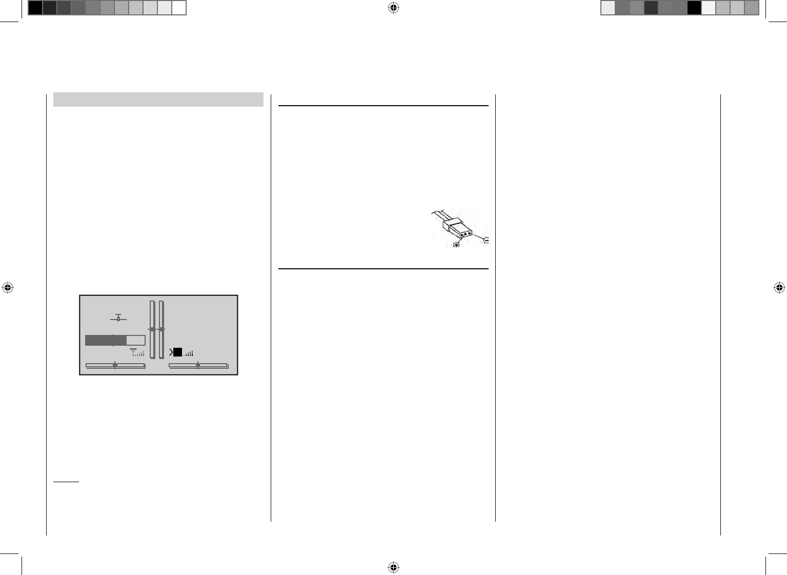
Joystick length adjustment
The length of both joysticks can be continuously
adjusted to adapt these transmitter controls to the pilot's
preference.
Hold the lower half of the knurled grip in place then turn
the upper section to release its counter-locked threads.
Now pull up or push down on the joystick's end to the
desired length. When the length is suitable, tighten the
counter-locked threads of the upper and lower sections
again.
Opening the transmitter housing
Carefully read the notices below before opening the
transmitter housing. It may be better if unexperienced
users ask a Graupner Service location to take care of
the procedures described below.
The transmitter should only be opened in the following
situations:
to convert a neutralized joystick to a non-neutralized •
joystick or a non-neutralized joystick to a neutralized
joystick.
to adjust joystick return tension.•
Switch off the transmitter before opening its cover
(power switch to "OFF").
Open the battery compartment as described on the
previous double-page, remove the battery and if a micro
SD card is inserted be sure to remove it too.
Once the battery and any micro SD card have been
removed, loosen the six countersunk screws on the rear
of the transmitter with a Phillips, size PH1, screwdriver,
see illustration.
Housing screw locations
Hold the two housing sections together by hand then
turn the transmitter upright over a suitable surface so
these 6 screws can fall out without getting lost. Now lift
up on the backplate carefully and turn it open to the right
like you would open a book.
A T T E N T I O N:
Two multi-conductor cables connect the backplate
with the transmitter electronics in the upper section.
These connections must not be damaged.
Important notices:
Make no modifi cations of any kind to the circuitry •
as this will void the guarantee as well as the
unit's offi cial permit.
Be sure not to touch the circuit boards with any •
metallic objects. Do not touch contacts with your
fi ngers.
Never switch the transmitter on when its housing •
is open.
When you close the transmitter again, be sure
that …
… no cables are caught between housing edges •
when the backplate is put into position.
… both housing parts are properly seated with one •
another before screwing them together. Never force
the housing sections together.
Turn the screws down into the existing housing •
threads without stripping them out.
… reconnect the battery.•
18 Operating notices
Operating notices
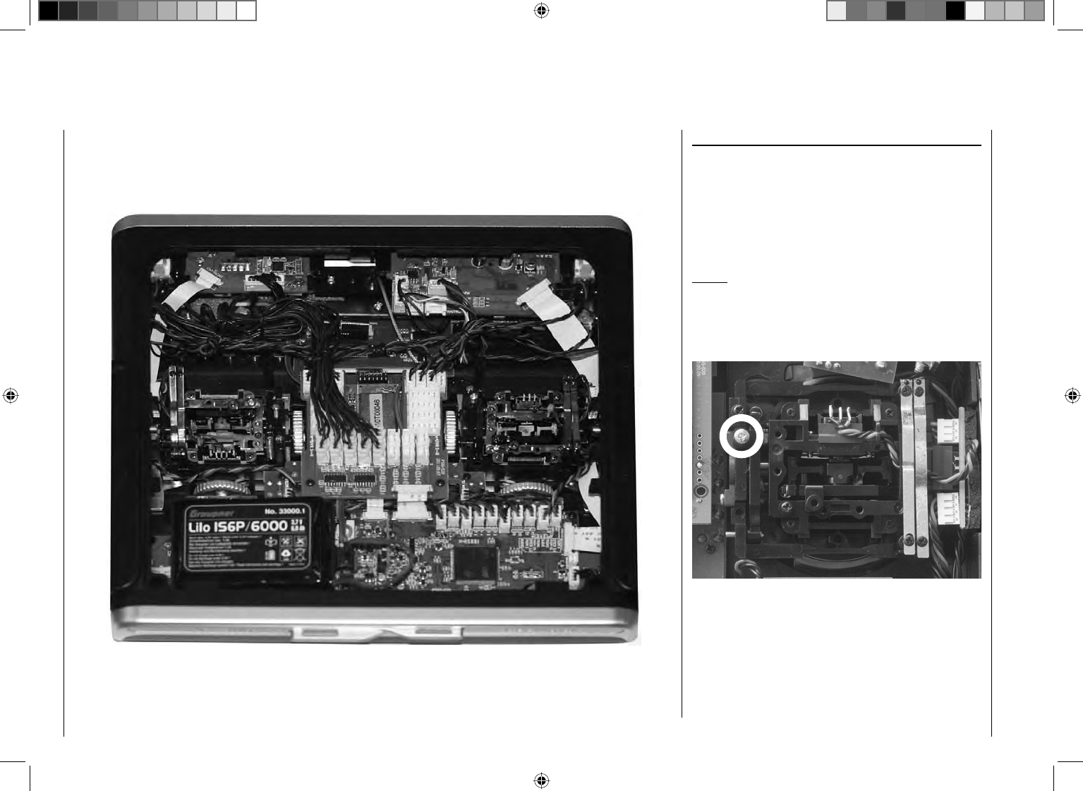
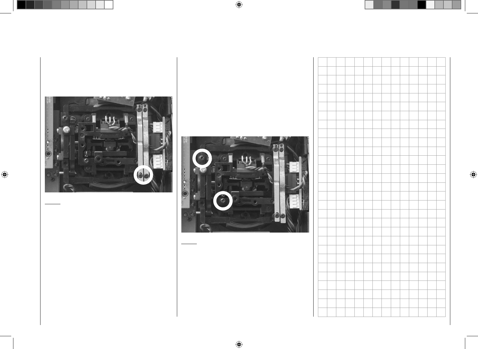
Converting joysticks
Neutralization
Both the left and the right joystick can be confi gured
for neutralized or non-neutralized operation as desired.
Open the transmitter housing as previously described.
To change the joystick's factory setting, locate the screw
shown in the fi gure below enclosed in a white circle.
Notice:
The aggregate for the right joystick is a mirror image of
the left joystick so the corresponding screw for the right
joystick is on the right side just below the middle.
Now turn this screw down until the respective joystick
is free to move from limit to limit - or turn the screw out
until the joystick again completely self-restoring.
19
Operating notices
Joystick restoring force
The joystick's restoring force can also be adjusted to the
pilot's preference. The adjustment is located next to the
return springs, see markings in the fi gure below.
Spring force for the given direction of motion can be
adjusted by turning the respective screw with a Phillips
screwdriver.
Right turn (clockwise) = return harder,•
Left turn (counter clockwise) = return softer.•
horizontal
horizontal
vertical
vertical
Notice:
The aggregate for the right joystick is a mirror image of
the left joystick so corresponding screws for the right
joystick are located to the right of the middle.
Brake spring and ratchet
The outboard screw of the two marked in the next fi gure
adjusts the braking force and the inboard screw adjusts
the strength of the ratchet for the respective joystick.
Notice:
The aggregate for the right joystick is a mirror image of
the left joystick so corresponding screws for the right
joystick are located at the top left.
20 Transmitter description
Transmitter description
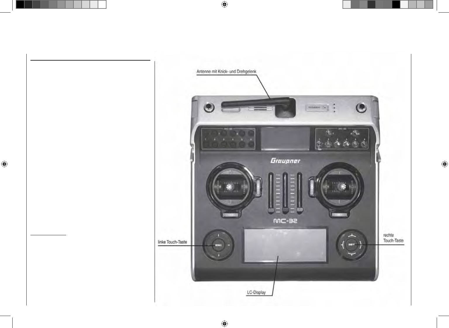
Transmitter operating elements
Attaching the transmitter's neck strap
There is an eyelet on the top side of the mc-32 HoTT
transmitter (see fi gure at the right) to which a neck strap
can be attached. This anchor point has been chosen
because the transmitter is optimally balanced here when
it hangs from the strap.
Order No. 1121 Neck strap, 20 mm wide
Order No. 70 Neck strap, 30 mm wide
Important notice:
In its delivered confi guration, the transmitter can only
operate any servos attached to the receiver by way
of the two joysticks. For reasons of fl exibility, all other
operating elements (CTRL 6 … 8, SW 1 … 9) are
designated as "free" by the software. These other
operating elements can be freely assigned to actuators
as described in the text for the "Control adjust" menu
on page 96 (winged aircraft models) or page 100
(helicopter models).
21
Transmitter description
Headset connector
The jack centered in the lower portion of the type
plate on the back of the transmitter is for connecting
conventional earplugs or a headset by way of a 3.5 mm
audio plug. (not included in the set)
The transmitter's acoustic signals as well as those
signals associated with the telemetry menu are output
via this connection. These announcements are made in
German language by default. More details about "Voice
output" can be found in the section "HIDDEN MODE"
beginning on page 28 and "Telemetry" beginning on
page 208.
The headset connector's volume control can be adjusted
in the "Voice volume" line of the "Basic Settings" menu,
see page 227.
Mini-USB connector
This connector socket is used to establish a connection
between the transmitter and a PC running a Windows
operating system (XP, Vista or Windows 7). The PC
software required, such as a suitable USB driver, can be
found on the download page for the given product on the
Graupner website at www.graupner.de.
Once the necessary software is installed on the PC, this
USB connection can be used to update the transmitter
or even just to set the date and time in the transmitter.
Data jack
For connecting the optionally available Smart-Box,
Order No. 33700.
Details about the Smart-Box can be found with the given
product in the Graupner RC main catalog or in Internet
at www.graupner.de.
Transmitter rear side
22 Transmitter description
Thus the transmitter is ready for operation.
To the contrary, teacher mode for the mc-32 HoTT
transmitter requires that the transmitter be switched
on prior to plugging in the respective cable.
Connect the other end of the cable to the desired unit 2.
in compliance with the given operating instructions
for that unit.
Important:
Be sure that all connectors are seated fi rmly in
their respective sockets.
Notice about fl ight simulators:
Because of the myriad of fl ight simulators available on
the market, it may be necessary to have the contact
layout of the audio plug or DSC module appropriately
modifi ed by Graupner Service.
DSC
Direct Servo Control
The acronym "DSC" is a carryover which stands for the
original "Direct Servo Control" function. However, in
HoTT systems the "direct servo control" function is no
longer available via a diagnose cable due to technical
reasons.
The standard two-pole DSC jack in the mc-32 HoTT
transmitter is used as the teacher or pupil jack as well
as an interface to fl ight simulators.
To ensure a proper DSC connection, please observe:
Make any necessary menu changes.
Refer to the section beginning on page 198 to
adapt the mc-32 HoTT transmitter to a teacher/pupil
system.
When operating a fl ight simulator or when operating 1.
the mc-32 HoTT transmitter as a pupil transmitter,
ALWAYS leave the transmitter's ON/OFF switch
in the "OFF" position as only in this position does
the transmitter's RF module remain inactive after
the DSC cable is inserted. This also reduces the
transmitter's power consumption somewhat.
The main status LED should now constantly
illuminate red and the transmitter's basic setup
screen should show the string "DSC pupil" on the
right just below the middle timer. At the same time,
the display of telemetry indicators will be suppressed.
PUPIL
#11
0:01h
Stop
Flt
«normal »
DSC
0:00
0:00
5.9V
0.0V
HoTT
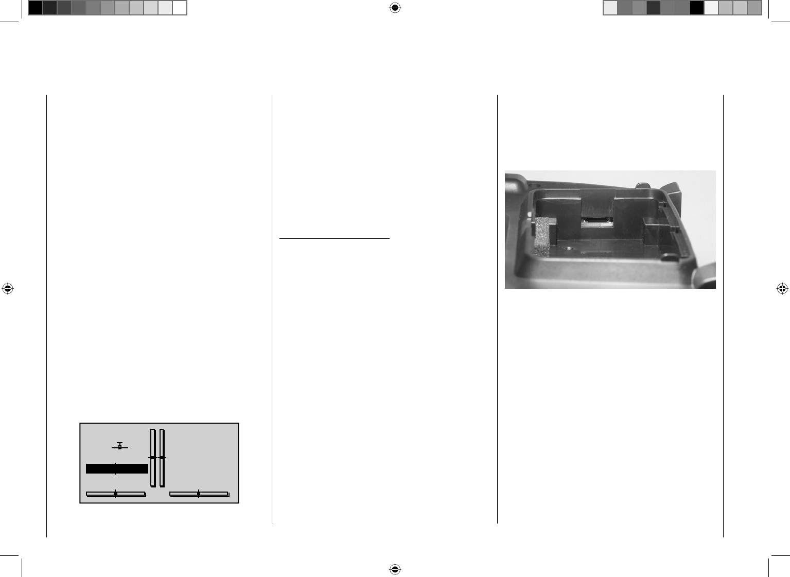
Data storage
Card slot
micro SD and micro SDHC
With the mc-32 HoTT transmitter switched off,
removing the battery compartment cover and the
transmitter's battery will make the card slot accessible
(located in the right sidewall of the battery compartment).
This card slot is intended for micro SD and micro SDHC
type memory cards.
All conventional micro SD memory cards up to 2 GB and
micro SDHC cards up to 32 GB storage capacity can
be used. However, as a manufacturer we recommend
the use of memory cards no larger than 4 GB as this is
completely adequate for all normal situations.
The type of memory card referred to here became
known in conjunction with digital cameras and cell
phones. It is to be pushed into the slot with its contacts
upward, front facing the rear wall and latched in position
there. After re-installing the battery and closing the
battery compartment, the transmitter can be switched on
again. The stylized image of a memory card will appear
in the basic setup screen to indicate the presence of the
inserted memory card.
23
Transmitter description
GRAUBELE
#01
3:33h
Stop
Flt
«normal »
K78
0:00
0:00
5.5V
5.2V
M
HoTT
Notice:
If a micro SD card is inserted, be sure to remove
it BEFORE taking off the transmitter's backplate.
Otherwise there is a risk of damaging the memory card.
Data acquisition / storage
The storage of data on the SD card is coupled to the
fl ight timer. If this timer is started – when a suitable
memory card is inserted in the card slot and a telemetry
link to the receiver exists – both the timer and data
acquisition will stop when the fl ight timer is stopped. The
fl ight timer is started and stopped as described in the
section "Timers (general)" on page 138.
While data acquisition is ongoing, the on-screen card
image will blink continuously at a slow rate.
The amount of data written on the memory card is
presented as a black bar graph which grows from left to
right as data fi lls the memory card.
After a data acquisition session is fi nished, there will
be an (empty) folder "Models" and a "LogData" folder
on the memory card. Within the "LogData" folder there
will be log fi les in sub-folders that are designated with
names in the format 0001_year-month-day.bin, 0002_
year-month-day.bin, etc. If a model memory folder is still
"unnamed" when the memory card is removed from the
transmitter and inserted into the card slot of a PC or
laptop, the respective log fi les can be found in a sub-
folder designated "NoName". There is a PC program
available on the transmitter's download web page at
www.graupner.de with which the stored data can be
evaluated on a compatible PC.
Importing voice fi les
As already mentioned in the section "Headsets" on
page 21, this connection can also be used to output
the transmitter's acoustic signals as well as those
signals and announcements associated with telemetry
menu settings. These announcements are made in
German language by default. These announcements
are summarized in a voice packet which is stored in a
transmitter-internal memory but they can be replaced
by a voice packet of a different language at any time.
More information about this can be found in the section
"HIDDEN MODE" beginning on page 28.
Importing/exporting model memories
Any model memory can be stored to an inserted memory
card or from an inserted card into the transmitter. This
feature is intended to support data exchange between
identical transmitters or even use as data backup.
More information about this can be found in the section
"Copying/deleting" beginning on page 64.
Notice:
Some special symbols that can be used in model names
are subject to specifi c restrictions associated with the
FAT or FAT32 fi le system used by the memory cards and
these special symbols will be replaced during the copy
process with a tilde (~).
24 Transmitter description - Display and keypad
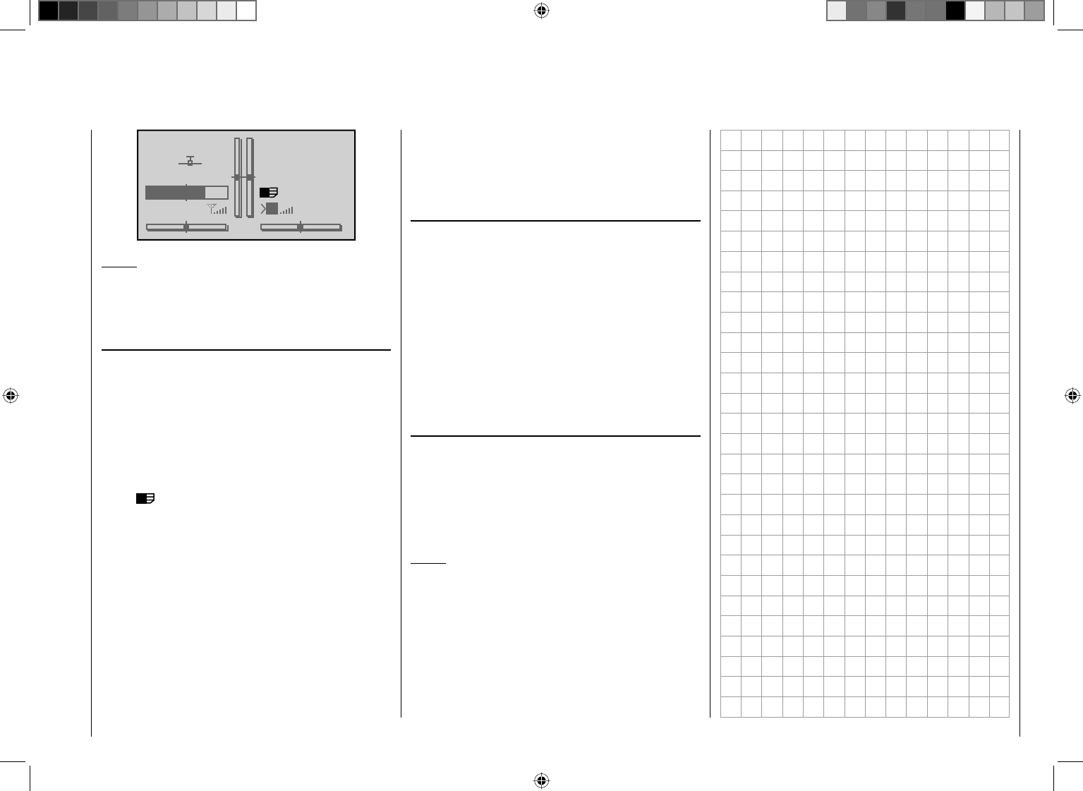
Display and keypad
Signal strength indicator
Battery time since last
re-charge in h:min
Flight timer in min:s
(upward/downward)
Stopwatch in min:s
(upward/downward)
Flight phase name
switchover between
fl ight phases by switch
Receiver power supply voltage
right touch pad:
ef cd
Paging / changing values
SET select / confi rm
Model name
Memory location 1 … 24
Battery voltage and charge state bars
(if the preset threshold voltage is underrun, a warning will
appear – see "Warnings" on page 36 –, and an acoustic
warning tone will sound)
optical indication of trim lever positions or, during activation
of speed controls CTRL 7 + 8, an alternative display of the
current positions of these controls
Model type indicator
(winged aircraft / helicopter)
left touch pad
ef cd paging
ef simultaneously pressed:
Change to the servo
display menu
ESC = cancel/return
ESC touched for about 1 s:
Change to the Telemetry menu
and return to basic display
possible warnings, see page 36
simultaneous pressing of
ef or cd = CLEAR
25
Transmitter description - Display and keypad
Operating the "data terminal"
Entry keys ESC and SET
Display symbols
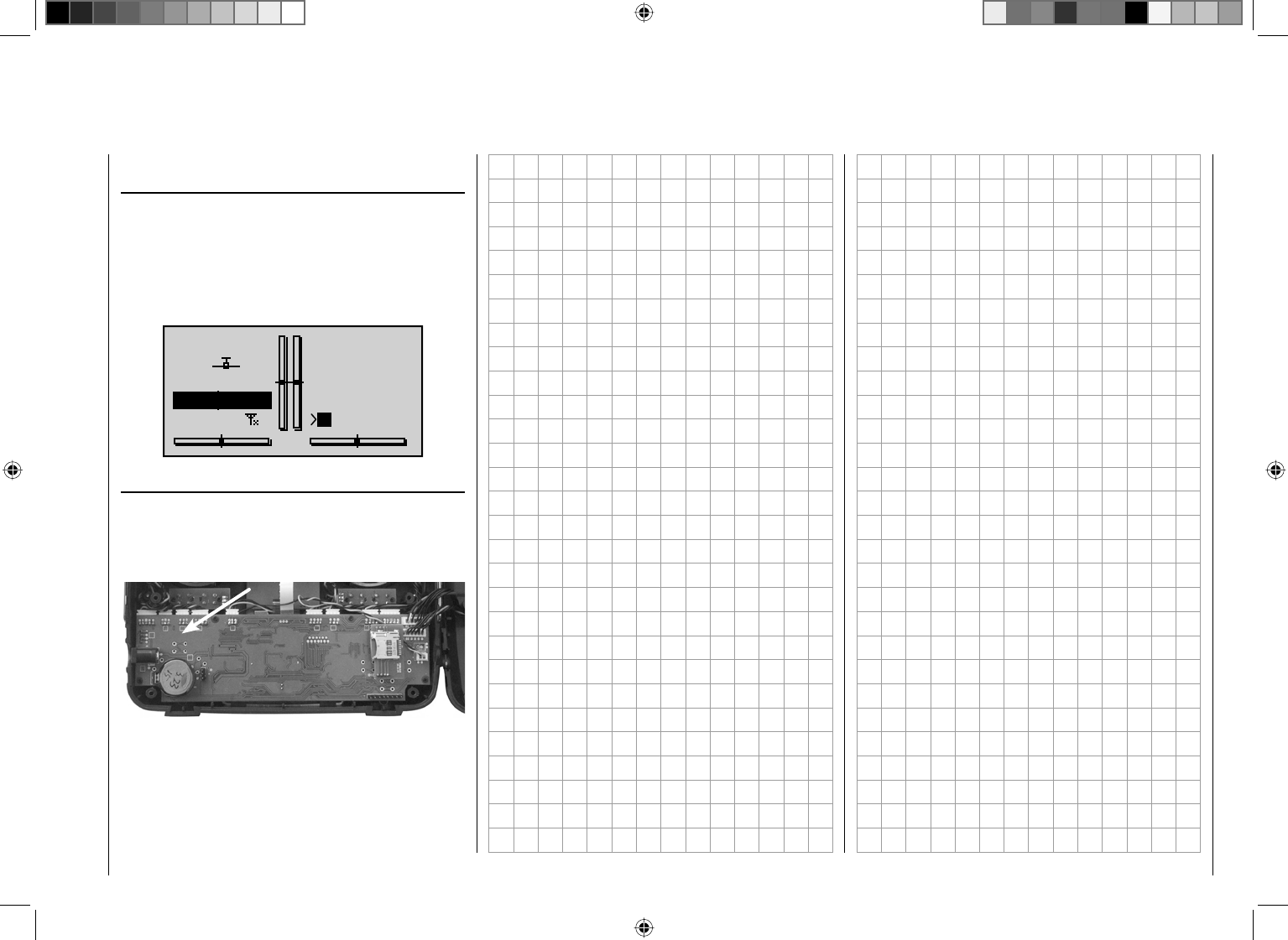
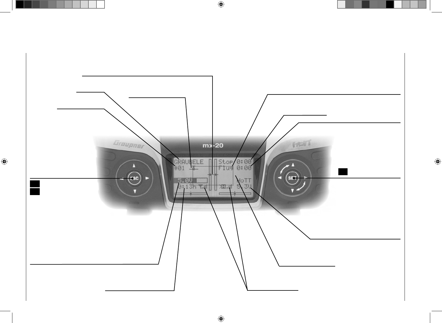
Displayed telemetry symbols
the active model memory has not yet "bonded"
with a HoTT receiver. More about the "Binding"
process, see page 69 or 75.
non-blinking: Switched off on RF transmitter side
blinking antenna symbol:
The last receiver bound to the active model is
inactive or out of range
>M x no telemetry signal to receive
>M signal strength indicator
>P indicator for pupil signal strength on the teacher
transmitter display
Keys left of the display
ESC• key
brief repeated pressing the ESC key will cause a
stepwise return to the function selection screen or
even further to the base screen. Any changes made
to settings remain.
Momentarily touching the ESC key for about 1 s
while in the base screen will open and close the
Telemetry menu.
arrow keys • ef cd
Momentarily pressing one of these keys will cause 1.
analogous paging in the given arrow direction
through lists, e. g. through the model selection list
or the multi-function list or within menus though
the menu's lines.
Simultaneous pressing on 2. ef will change the
transmitter's base screen and almost any menu
position to the "Servo display" menu.
Keys to the right of the display
SET• button
After switching the transmitter on, briefl y pressing 1.
the SET key will cause a jump from the displayed
base screen to the Multi-function menu. In the
same manner a selected menu can now be called
up with the SET key.
Momentarily pressing the 2. SET key from within
the Basic Settings menu will activate / deactivate
(confirm) the given setting fi elds.
arrow keys • ef cd
1. "Paging" through the Multi-function menu and
the menu lines within the Basic Settings menu
analogous to the arrow keys of the left touch pad.
2. Select or set parameters in setting fi elds after they
have been activated by briefl y touching the SET
key, whereby the fc keys and ed are used for
the same corresponding functions. In this case it
is completely irrelevant which of these two keys
are used.
By briefl y pressing the 3. cd keys simultaneously
or ef an altered parameter value for the active
entry fi eld will again be restored to its default
value (CLEAR).
Notice:
Touching the given touch pad does not itself initiate •
the given action but rather the end of the touch.
In the event the touch pads do not exhibit any •
functionality immediately after switching the
transmitter off and then on again right away, this is
not a fault. Just switch the transmitter off again then
wait for several seconds before switching it on again.
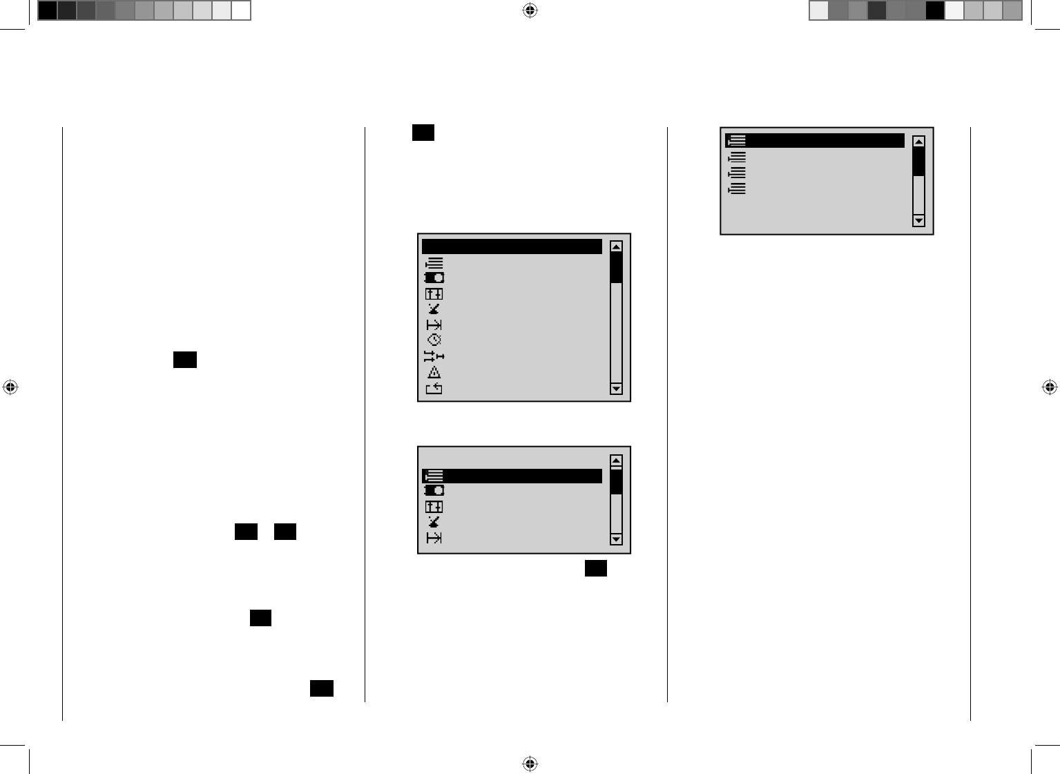
26 Transmitter description - Shortcuts
Shortcuts
The following key combinations can be used to directly
call up certain menus and options:
CLEAR•
Brief simultaneous activation of the cd keys or
ef on the right touch pad will restore the active
entry fi eld's changed parameter value back to its
default value.
"• Servo screen"
Brief simultaneous activation of the ef keys of the
left touch pad will cause a jump from the transmitter's
base screen or from almost any menu position to the
"Servo" menu, see page 230.
"• Telemetry" menu
Press the center ESC key in the left touch pad for
about 1 s to call up the "Telemetry" menu from the
transmitter's base screen, see text beginning on
page 208, or to return to the base screen again.
Graphic display of telemetry data•
Briefl y touching one of the arrow keys of the left
or right touch pad will cause a jump from the base
screen directly to the transmitter's graphic display
of telemetry data or will allow paging back and forth
between individual graphic displays.
Briefl y touching the centered ESC or SET key will
cause a return back to the base screen.
"• HIDDEN MODE"
(language selection and contrast)
Press and hold arrow keys cd of the left touch
pad then momentarily touch the SET key of the right
touch pad, see next double-page.
Entry lockout•
Entry lockout is activated and deactivated from the
base screen by simultaneously pressing the ESC
and SET keys for a little longer (about 2 s).
Quick-Select•
From the multi-function list, a jump can be made to a
"Structure overview" by a brief, simultaneous touch
on the cd or ef keys of the right touch pad.
Menus are arranged in clear groups in this overview.
Memory
Servo settings
Transm. controls
Switches
Flight phases
Timers
Mixers
Special funct.
Global functions
All menus
Now the desired group can be selected with the cd
arrow keys of the left or right touch pad …
Memory
Servo settings
Transm. controls
Switches
Flight phases
All menus
… and then briefl y touching the center SET key in
the right touch pad. As soon as the key is released,
only the respective generic term for the given menu
will remain listed. For example:
Copy / Erase
Suppress menus
Suppress models
Model select
27
Transmitter description - Concealed menu columns
Concealed menu columns
Some menus have concealed columns to improve
legibility. Menus with concealed columns can be
recognized by virtue of a triangle pointing to the right in
the bottom left corner of the screen. For example, in the
menu "Servo settings":
S1
S2
S3
Rev cent +
trv
0%
0%
0%
100% 100%
100% 100%
100% 100%
0%
0%
100% 100%
100% 100%
S4
S5
In this menu, e. g. the column "lim" +" (servo travel limit)
to the right of column "- travel +" is "concealed".
To reach this column, use the pointing triangle at the
bottom left of the screen to push the frame marker with
the arrow key f of the left or right touch pad to just
beyond the column for "- travel +":
S1
S2
S3
Rev cent +
lim
0%
0%
0%
150% 150%
150% 150%
150% 150%
0%
0%
150% 150%
150% 150%
S4
S5
To again return to the now-concealed column "- travel
+" or even further to the left, push the frame marker with
arrow key e of the left or right touch pad appropriately
to the left:
S1
S2
S3
Rev cent +
trv
0%
0%
0%
100% 100%
100% 100%
100% 100%
0%
0%
100% 100%
100% 100%
S4
S5
This procedure is analogous for the other menus.
28 Transmitter description - Hidden mode
The mc-32 HoTT transmitter's "HIDDEN MODE" can
be reached from almost any menu position by pressing
and holding the cd arrow keys of the left touch pad
and the SET key of the right touch pad for about one
second until the screen shown below is displayed.
¿ HIDDEN MODE ¿
CONTRAST
LANGUAGE
0
DEUTSCH
VOICE DEUTSCH
STICK CALI.
CONTRAST
The screen's contrast characteristic can be adapted as
needed in this screen's "CONTRAST" line, as described
in more detail on pages 226/226, by tapping on the
center SET key of the right touch pad. Tapping again
on the SET or ESC keys will cause a return to line
selection.
The line …
LANGUAGE
… can be reached by tapping arrow keyd in the left
or right touch pad. One of the transmitter's available
languages can then be selected from the screen which
appears.
¿HIDDEN MODE ¿
CONTRAST
LANGUAGE
0
DEUTSCH
VOICE DEUTSCH
STICK CALI.
Activate language selection by pressing on the center
HIDDEN MODE
Language selection and display contrast
SET key in the right touch pad.
¿HIDDEN MODE ¿
CONTRAST
LANGUAGE
0
VOICE DEUTSCH
STICK CALI.
DEUTSCH
Now the default language "GERMAN" can be replaced
with the desired language by making a selection with the
arrow keys of the right touch pad. For example:
¿ HIDDEN MODE ¿
CONTRAST
LANGUAGE
0
VOICE DEUTSCH
STICK CALI.
ENGLISH
Confi rm the selection by tapping again on the center
SET key in the right touch pad. All settings stored in the
transmitter remain intact after a change of language has
been made.
The following languages are available for selection at
the time this handbook was printed:
German•
English•
French•
The Italian and Spanish languages are planned for
inclusion at a later point in time. These will then be
made available by way of an update download from the
transmitter's web page at the Graupner website
www.graupner.de.
VOICE TRIGGER
As mentioned in section "Headsets" on page 21, the
transmitter's acoustic signals as well as those signals
and announcements associated with the telemetry
menu can be output by way of the headset connector.
These announcements are made in German language
by default. These announcements are summarized in
a voice packet which is stored in a transmitter-internal
memory but they can be replaced by a voice packet of a
different language at any time.
The following languages are available for selection at
the time this handbook was printed:
German•
English•
French•
The Italian and Spanish languages are planned for
inclusion at a later point in time. These will then be made
available on the transmitter's download web page at the
Graupner website www.graupner.de.
The given active language packet can then be swapped
out either with the PC program (also available as a
download from the transmitter's web page at
www.graupner.de) or per SD card as described below.
Preparation
If not already done, insert the SD card or SDHC card
into the transmitter as described on page 22. Now
when the transmitter is switched on it will perform
some operations which will include the creation of a
"VoiceFile" on the memory card.
Take this memory card, which has now been prepared
by the transmitter, out of the transmitter and insert it
into a suitable card reader. If necessary, attach the card
reader to your PC or laptop. Now copy the language
29
Transmitter description - Hidden mode
packet downloaded from the transmitter's web page (e.g.
"voice_gb.vdf") into the folder created by the transmitter.
Now take the memory card out of the card reader and
re-insert it into the transmitter. Once the memory card is
inserted in the transmitter, switch the transmitter on with
RF switched off.
RF on/off?
ON
Please select
OFF
Language change
Use the left or right arrow touch key to select the line
"VOICE".
¿ HIDDEN MODE ¿
CONTRAST
LANGUAGE
0
VOICE DEUTSCH
STICK CALI.
ENGLISH
Activate language selection by pressing the center SET
key in the right touch pad.
¿ HIDDEN MODE ¿
CONTRAST
LANGUAGE
0
VOICE
STICK CALI.
ENGLISH
DEUTSCH
Now use the right touch pad arrow keys to replace the
default language "DEUTSCH" with the language you
want. For example:
¿ HIDDEN MODE ¿
CONTRAST
LANGUAGE
0
VOICE
STICK CALI.
ENGLISH
ENGLISH
Confi rm your selection with another tap on the center
SET key in the right touch pad. The selected language
packet will be loaded into the transmitter's memory.
¿ HIDDEN MODE ¿
CONTRAST
LANGUAGE
0
VOICE
STICK CALI.
ENGLISH
ENGLISH
22/100%
I
The loading process is fi nished as soon as the progress
bar at the lower edge of the display disappears.
¿ HIDDEN MODE ¿
CONTRAST
LANGUAGE
0
VOICE
STICK CALI.
ENGLISH
ENGLISH
When this process is fi nished, switch off the transmitter.
All settings stored in the transmitter remain intact after a
change of language has been made.
Notice:
If the warning …•
RF
MUST BE
OFF
OK
… appears, then the transmitter's RF radiation is still
active. Jump to the "Basic settings" menu, select
the "RF transmit" line, select its "OFF" option and
then repeat the procedure
If the warning …•
SD-CARD
INSERT
OK
… appears then the transmitter does not detect a memory
card in its card slot or the card found cannot be read.
If the warning …•
MISSING
IMPORT
DATA
OK
… appears then the transmitter could not fi nd an
appropriate fi le on the inserted memory card.
JOYSTICK CALIBRATION
If you feel the neutral position of your self-calibrating
joysticks (controls 1 … 4) are not exactly 0 % of
their control travel, then this can be checked and, if
necessary, corrected as follows.
Jump to the "Model select" menu and initialize a free
model memory as described on page 60. Whether the
model to be initialized is a winged aircraft or a helicopter
is irrelevant.
30 Transmitter description - Hidden mode
Wait for the notices which typically appear in the base
screen following a model change then jump to the
"Servo display" menu, for example by simultaneously
touching the ef keys of the left touch pad (WITHOUT
any interim change to trim settings or other program
settings).
If all four of your transmitter's joystick functions are still
self-neutralizing, this display should ideally look like the
one shown below.
1
3
5
7
+
0%
0%
9
11
0%
0%
2
4
6
8
+
0%
0%
0%
0%10
12 0%
–100%
0%
0%
Otherwise the graph bars show current setting
percentages for joystick control functions which are not
self-neutralizing – typically for the "K1", throttle/brake or
throttle/pitch, control stick. For example, if the throttle/
brake control stick is in its "quarter-throttle" position, the
display would appear as shown below.
1
3
5
7
+
0%
0%
9
11
0%
0%
2
4
6
8
+
0%
0%
0%
0%10
12 0%
–50%
0%
0%
One after the other, put both joysticks into each of their
four possible limit positions without exerting force at
the limit position. In each of these eight possible limit
positions, the – side dependent – indication for exactly
-100 % or +100 % should be displayed. For example,
if Control 2 is at its left limit and the other three joystick
functions are in their respective middle positions then
your transmitter's display should look like the one shown
below.
1
3
5
7
+
0%
0%
9
11
0%
0%
2
4
6
8
+
–100%
0%
0%
0%10
12 0%
0%
0%
0%
Regardless of the number of self-neutralizing joystick
functions available on your transmitter, if these checks
produce four 0 % results and eight 100 % results then
your transmitter's joysticks are optimally calibrated. You
can terminate this process then, if appropriate, delete
the model memory just created.
Otherwise jump (as described at the outset of the
previous double page) to the "Stick cali." line in the
"HIDDEN MODE" menu then briefl y touch the center
SET key in the right touch pad.
STICK CALIBRATION
CONTRAST
LANGUAGE
0
VOICE DEUTSCH
ENGLISH
STICK CALI.
0%
d
c
The arrow keys ef of the right touch pad will now
allow you to cyclically select the four calibrated joystick
planes, e.g. the left/right plane of the right joystick.
STICK CALIBRATION
CONTRAST
LANGUAGE
0
VOICE DEUTSCH
ENGLISH
STICK CALI.
0%
d
c
Now position the right joystick – without exerting extra
force – to its left limit corresponding with the on-screen
blinking arrow pointing to the left.
STICK CALIBRATION
CONTRAST
LANGUAGE
0
VOICE DEUTSCH
ENGLISH
STICK CALI.
+100%
d
c
… and briefl y touch the center SET key in the right
touch pad. This concludes this example calibration of the
right joystick's left limit. The circle in the middle of the
stylized joystick plane will now blink as confi rmation of
the calibration.
STICK CALIBRATION
CONTRAST
LANGUAGE
0
VOICE DEUTSCH
ENGLISH
STICK CALI.
+100%
d
c
Now release the self-neutralizing joystick so it can return
to its center position and then tap again on the center
SET key to calibrate the joystick's centered position. The
right arrow marker will begin to blink.
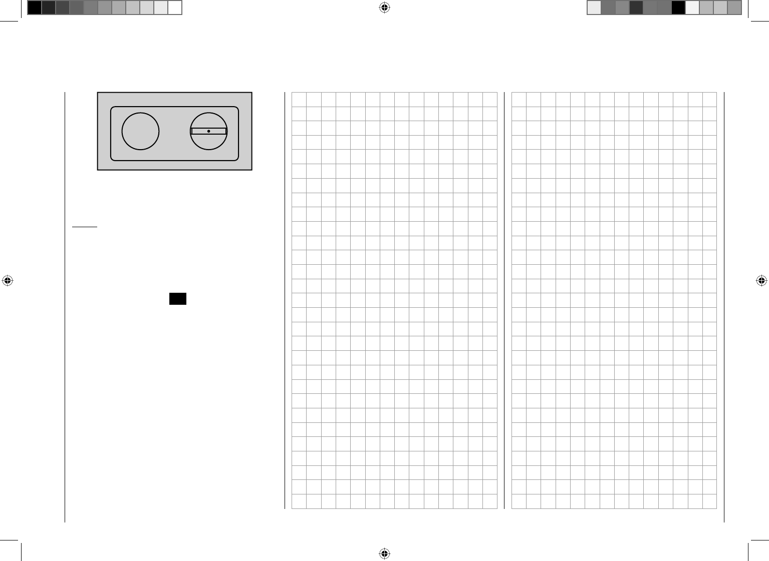
31
Transmitter description - Hidden mode
STICK CALIBRATION
CONTRAST
LANGUAGE
0
VOICE DEUTSCH
ENGLISH
STICK CALI.
0%
d
c
Repeat the calibration process for the right limit of the
right joystick. The other joystick planes are calibrated
analogously.
Notice:
Correct any bad calibrations by repeating the •
respective process.
Within a given joystick plane, each of the three •
calibration positions can be selected directly with the
cd arrow keys of the left or right touch pad.
Briefl y touching the center ESC key of the left touch pad
will terminate the process and return to the sub-menu
"Stick cali.".
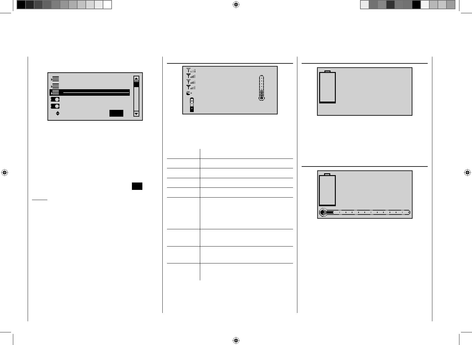
32 Transmitter description - Telemetry data display
As described on page 220 in the context of sub-menu
"SENSOR SELECT" for the "Telemetry" menu …
Model select
Base setup model
Model type
Copy / Erase
Suppress models
Suppress: TOG
… the output of sensors attached to the receiver can be
processed and activated for graphic presentation on the
screen. This data is then appropriately displayed by the
graphic indicators described below.
These graphic elements can be reached from the
transmitter's base screen by briefl y touching the e or f
keys of the left or right touch pad. Page back and forth
between individual graphic elements with the same keys
and return to the base screen again with the ESC key.
Notice:
The sequence of the following element descriptions
corresponds to their selection sequence when touching
the f key.
More details about the following named modules can be
found in the appendix and in Internet at www.graupner.
de in the web page for the given product.
RECEIVER
RX–S QUA: 100%
RX–S STR: 100%
TX–dBm: 33dBm
RX–dBm: 33dBm
RX–VOLT:4.8 TMP
L–PACK: 10ms
CH OUTPUT TYPE:ONCE
R–LOW V:4.6 +22°C
This screen presents the "RX DATAVIEW" of the
Telemetry menu's "SETTING & DATA VIEW", see page
209, with data processed and displayed graphically.
The displayed items are as follows:
Value Explanation
RX-S QUA signal quality in %
RX-S ST signal strength in %
RX-dBm reception power in dBm
TX-dBm transmit power in dBm
V PACK Indicates the longest time span in ms
in which data packages are lost in the
transmission from the transmitter to the
receiver.
RX-VOLT current operating voltage of the
receiver's power supply in volts
M-RX V lowest receiver operating voltage since
last startup, in volts
TMP the thermometer depicts the receiver's
current operating temperature
AKKU 1 (GENERAL + ELECTRIC modules)
0.0V
0.0A
0mAh
This display depicts current voltage, current current
draw and, if attached, the expended capacity of "Batt 1"
connected to the General-Engine (Order No. 33610),
General-Air (Order No. 33611) or Electric-Air module
(Order No. 33620).
SENSOR 1 (GENERAL + ELECTRIC module)
0.0V
0°C
SENSOR 1
If attached, this display depicts currenly measured voltage
and temperature from a "T(EMP)1" temperature/voltage
sensor, Order No. 33612 or 33613 for General-Engine
(Order No. 33610), General-Air (Order No. 33611) or
Electric-Air module (Order No. 33620).
Telemetry data display
33
Transmitter description - Telemetry data display
SENSOR 2 (GENERAL + ELECTRIC modules)
0.0V
0°C
SENSOR 2
If attached, this display depicts currently measured
voltage and temperature from a "T(EMP)2" temperature/
voltage sensor, Order No. 33612 or 33613 for General-
Engine (Order No. 33610), General-Air (Order No. 33611)
or Electric-Air module (Order No. 33620).
Rotary speed sensor
U/min
0
00
If attached, this display depicts the speed measured
by a speed sensor, Order No. 33615 or 33616, for a
General-Engine (Order No. 33610), General-Air (Order
No. 33611) or Electric-Air module (Order No. 33620).
Notice:
The appropriate blade count must fi rst be set in the
module's telemetry menu before the correct speed can
be displayed.
Vario
0.0
0m
m
s
If attached, this display will depict altitude relative to
location or starting location (in m) as well as the current
ascent/decent rate (in m/s) from data provided by a
GPS-/Vario module (Order No. 33600) or Vario module
(Order No. 33601) connected to the receiver's telemetry
connection.
GPS
N
WE
S
Kmh
0
km/h
DIS
m
m/s
ALT
m
0
0
0.0
0
If attached to the receiver, this display will depict the
data from a GPS module with integrated Vario, Order
No. 33600.
The displayed items are as follows:
Value Explanation
km/h Speed
DIS horizontal distance in m
m/s ascent/decent rate in m/s
ALT altitude relative to starting location in m
GPS
NRXSQ 0
DIS 0m
ALT 0m
0.0m/1s
0m/3s
0m/10s
N 0°00.0000
E 0°00.0000
WE
S
Kmh
0
If attached to the receiver, this display will depict the
data from a GPS module with integrated Vario, Order
No. 33600.
Aside from the model's current position and speed, the
center section of this screen will also display current
altitude with respect to the starting location as well as
the model's current ascent/decent rate in m/1 s, m/3 s
and m/10 s, current reception quality and the model's
distance from its starting location.
The displayed items are as follows:
Value Explanation
W / N / E / S west / north / east / south
Kmh speed
RXSQ return channel signal strength
DIS distance
ALT current altitude with respect to starting
m/1 s m/1 s ascent/decent rate
m/3 s m/3 s ascent/decent rate
m/10 s m/10 s ascent/decent rate
34 Transmitter description - Telemetry data display
VARIO
RXSQ
0
MAX
0m
MIN
0m
ALT
0
H
L
m/1s
0.0
m/3s
0.0
m/10s
0.0
If attached to the receiver, this screen will display the
data acquired by a Vario module, Order No. 33601.
The displayed items are as follows:
Value Explanation
ALT current altitude
RXSQ Signal strength of the signal received
by the receiver in %, see page 209.
MAX the preset maximum altitude limit
relative to starting location at which,
when exceeded, will cause an audible
warning to be sounded
MIN the preset minimum altitude limit
relative to the starting location at
which, when underrun, will cause an
audible warning to be sounded
m/1 s m/1 s ascent/decent rate
m/3 s m/3 s ascent/decent rate
m/10 s m/10 s ascent/decent rate
ELECTRIC AIR MODULE
0.0V 0m/3s
BAT1 0m/1s
BAT2
0.0V T2 0°C
T1 0°C
0
1L0.00
2L0.00
3L0.00
4L0.00
5L0.00
6L0.00
ALT 0m
7L0.00
0.0V 0A
0.0V 0m/3s
BAT1 0m/1s
BAT2
0.0V T2 0°C
T1 0°C
0
1H0.00
2H0.00
3H0.00
4H0.00
5H0.00
6H0.00
ALT 0m
7H0.00
0.0V 0A
If attached to the receiver, this screen will display
the data acquired by an Electric-Air module, Order
No. 33620. More details about this module can be found
in the appendix or in Internet at www.graupner.de in the
web page for the given product.
Depending on how this module is equipped with
sensors, this screen can permanently display the data
shown in the adjacent table.
The current voltage of up to two batteries (BAT1 and
BAT2), up to two temperature measurements (T1 and
T2), current altitude with respect to the starting location,
the model's ascent/decent rate in m/1 s and m/3 s and,
in the middle of the screen, the current draw currently
being taken from a power source.
Along the right edge of the screen is a table of
alternating values for cell voltages at balancer
connections (L) or voltages for up to 7 attached battery
cell packs (H).
The displayed items are as follows:
Value Explanation
V current voltage
A current current
BAT1 / BAT2 battery 1 or 2
ALT current altitude
m/1 s m/1 s ascent/decent rate
m/3 s m/3 s ascent/decent rate
T1 / T2 temperature of sensor 1 or 2
L or H cell voltage of cells 1 … 14 (14 max)
L = balancer connection 1
H = balancer connection 2
GENERAL MODULE
0.0V
BAT1
BAT2
0.0V T2 0°C
T1 0°C
E FUEL F
CELL V
1:0.00
2:0.00
3:0.00
4:0.00
5:0.00
6:0.00
0
0.0V
BAT1
BAT2
0.0V T2 0°C
T1 0°C
E FUEL F
ALT
0m
0m1
0m3
0.0A
POWER
0.0V
0
If attached to the receiver, this screen will display the
data acquired by a General-Engine module, Order
No. 33601, or a General-Air module, Order No. 33611.
More details about these modules can be found in the
35
Transmitter description - Telemetry data display
appendix or in Internet at www.graupner.de in the web
page for the given product.
Depending on how this module is equipped with
sensors, this screen can permanently display the data
shown in the table below.
The current voltage of up to two batteries (BAT1
and BAT2), the measurement results of up to two
temperature sensors (T1 and T2) and a fi ll level gage for
the fuel tank.
An alternating display along the screen's right edge will
display a list of current cell voltages for a LiPo battery
with up to six cells or operational data (current altitude
with respect to the starting location, ascent/decent m/1 s
and m/3 s, current current being drawn in amperes and
current voltage of the battery connected to the sensor).
The displayed items are as follows:
Value Explanation
BAT1 / BAT2 battery 1 or 2
FUEL fuel level / tank gage
E / F empty /full
T1 / T2 temperature of sensor 1 or 2
CELL V voltage of cells 1 … 6 (6 max)
ALT current altitude
0m1 m/1 s ascent/decent rate
0m3 m/3 s ascent/decent rate
A current draw i amperes
V battery voltage
36 Transmitter description - Warning notices
Warning notices
BIND N/A
OK
"Bind not available"
A receiver has not yet been
bound to the currently active
model memory. Briefl y touching
the SET key will cause a direct
jump to the appropriate option.
RF on/off?
OFF
ON
Please select Please select RF transmission
"ON" or "OFF".
battery
needs
charging
Operating voltage is too low
Fail Safe
setup
t.b.d.
Failsafe has not yet been
activated
MISSING
IMPORT
DATA
OK
A suitable language fi le
cannot be found on the
memory card
Throttle
too
high !
Helicopter throttle joystick or
limiter too high
RF
MUST BE
OFF
OK
Prompt to switch off RF
transmission
(language fi le can only be
loaded when RF is switched off)
Warning notices
CAN‘T
RECEIVE
DATA
OK
No bound receiver in range
No
pupil
signal
Connection between teacher
and pupil is interrupted
SD-CARD
INSERT
OK
No SD or SDHC memory card
in the card slot or card is not
legible
Is the "wireless teacher/pupil connection" that was •
active when the transmitter was last used to be
continued, CONT or switched off OFF?
TRAINER
Wireless Link
ACT INH
After being switched on, the transmitter has not •
been used within the time limit preset in the "Power-
on beep" line of the "Basic Settings" menu, see
page 227. The message …
Power on waning
is active!
… will appear in the screen, the center LED will
alternately blink red and blue and an acoustic
warning tone will sound.
If the transmitter continues unused it will
autonomously switch itself off after one minute.
When battery voltage is too low, a model change is •
blocked for reasons of safety. The screen will show
an appropriate message.
not possible now
voltage too low
37
Transmitter description - Function fi elds, position indicator and entry lockout
As soon as one of the proportional controls (CTRL 7 & 8)
in the middle console is turned, a small symbol will appear
to the left of the two vertical position indicators.
At the same time, for the duration of the control's
operation, the position indicator for the two vertical bars
in the middle will change from displaying current trim
position to a display of the respective current position of
the proportional controls CTRL 7 & 8.
Logically, the left proportional control (CTRL 7) is
displayed by the left bar indicator and the right bar
indicator displays the position of the right proportional
control (CTRL 8). The two horizontal bars continue to
show current trim positions of respective joystick trim
controls.
GRAUBELE
#01
3:33h
Stop
Flt
K78
0:00
0:00
RX0.0V
5.2V
M
HoTT
About 2 seconds after operating one of the proportional
controls has ended, the display will again revert to
display of current trim positions of the four trim controls
generated by the two joysticks.
Position indicator
Proportional controls, CTRL 7 and 8
The touch keys can be locked out to prevent unintended
access and operation of settings. This lockout is
established (when the mc-32 HoTT transmitter is
displaying its base screen) by simultaneously pressing
and holding both the ESC and SET keys for about two
seconds. This lockout condition is indicated by a key
symbol, located at the intersection point of the trim bars,
which is displayed in reverse video.
GRAUBELE
#01
3:33h
Stop
Flt
«normal »
K78
0:00
0:00
5.5V
5.2V
M
HoTT
The lockout is effective immediately but controls remains
operationally ready.
The lockout can be removed by again touching and
holding the ESC and SET keys for about two seconds.
A lockout condition is also removed the next time the
transmitter is switched on.
Function fi elds in the display
SEL,STO,SYM,ASY, ,
Entry lockout
Depending on the given menu, certain function fi elds will
appear on the bottom display line.
CLR SEL STO SYM ASY
A marked function is activated by tapping on the SET
key.
Function fi elds
CLR• (clear) delete
SEL• (select): selection
STO• (store): store (e. g. control position)
SYM• set values symmetrically
ASY• set values asymmetrically
• switch symbol fi eld
(assignment of all types of switches)
• within a menu, change to the
second page (menu continuation)
38 Putting the transmitter into operation
Preliminary remarks
Graupner's HoTT system theoretically permits
simultaneous operation of more than 200 models.
However, because of the interspersed radio-frequency
utilization permitted by certifi cation for the 2.4 GHz
ISM band, this number is signifi cantly lower in practical
application. Nevertheless, in general more models
can be operated simultaneously in the 2.4 GHz band
than would be the case in conventional 35 or 40 MHz
frequency bands. The real limiting factor is – as often
before – is still likely to be the size of available
operating space (i.e. airspace for aircraft). Alone the fact
that it is no longer necessary to coordinate transmitting
frequencies with other pilots in the vicinity (which is
sometimes quite diffi cult in broken landscapes, such as
on hillside slopes) represents an enormous boost for
remote control operating security.
Battery charged?
Since the transmitter is delivered with an empty (not
charged) battery, the battery must fi rst be charged
according to the charging instructions on page 14.
Otherwise a warning tone will be sounded when the
low voltage threshold, preset in the "Batterie warning"
line of the "Basic Settings",
is underrun. This low voltage
threshold can be set, as
described on page 226. When
this threshold is underrun,
a warning tone will be sounded and an appropriate
message will be overlaid on the base screen.
Transmitter startup
After being switched on, the message shown below will
appear in the transmitter's screen for about two seconds.
RF on/off?
OFF
ON
Please select
Within this brief period you may be able to switch off RF
transmission by using the c or f key of the right touch
pad to shift the query's response from "ON" to "OFF"
such that the ON option is displayed in normal video and
the OFF option is highlighted in reverse video.
RF on/off?
ON
Please select
OFF
Now switch the RF module off by tapping on the center
SET key in the right key pad.
The center LED, which in the meantime has been
illuminating in blue, will change its color to red again and
the transmitter's display will show the screen depicted
below.
GRAUBELE
#01
0:33h
Stop
Flt
K78
0:00
0:00
0.0V
5.2V
M
HoTT
The symbol combination means that the currently
active model memory has already "bonded" with a
Graupner HoTT receiver in the past but there is no
connection to this receiver at the moment. (In this
example, RF transmission has been switched off.)
If the transmitter were to be switched on without
switching off RF transmission, the center LED would
illuminate in blue and the symbolic transmitter antenna
battery
needs
charging
Putting the transmitter into operation
Preliminary remarks about the mc-32 HoTT transmitter
in the screen would blink. At the same time, an acoustic
warning will sound until a connection is established with
the respective receiver. As soon as this connection is
established, the "x" at the base of the antenna symbol
will be replaced by a fi eld strength indicator, for example
, and the optical and acoustic warnings will stop.
If a telemetry connection has also been established for
the incoming signal, that is output by the receiver in the
model, then the right side of this same screen line will
display a similar indication of signal strength for this
reception of the receiver's transmitted signal (>M) as
well as the current voltage of the receiver's power supply.
On the other hand, if the screen displays the symbol
combination and the center LED illuminates in red
continuously then the currently active model memory is
not "bonded" to any receiver.
Under-voltage warning
If transmitter voltage drops below the adjustable
threshold specifi ed in the "General Settings" menu,
see page 226 (default value, 4.7 V), an optical and an
acoustic under-voltage warning will be issued.
Important notices:
The transmitter in the set is already preset, as •
delivered, with default values which are correct
for operation in most European countries (except
France).
If the remote control system is to be operated in
France then the transmitter MUST be changed over
to "FRANCE" mode, see page 227. IN NO CASE may
the Universal/EUROPE mode be used IN FRANCE.
The receiver included in the set • with the mc-32
HoTT 2.4 transmitter (and already bound to the
transmitter by settings made in the factory) is
39
Putting the transmitter into operation
capable of operating up to 12 servos.
In order to achieve the greatest possible
fl exibility but still preclude unnecessary
inadvertent operator errors, control channels 5 …
12 have not been assigned to any controls. This
means that servos connected by way of these
channels will remain in their middle positions
until an operator element has been assigned.
Practically all mixers are initially inactive for
this same reason. More about this can be found
on page 96 (winged aircraft) or 100 (helicopter
models).
The fundamental procedure for initial •
programming of a new model memory location
can be found on page 60 and the programming
examples that begin on page 236.
When the remote control system is switched on, •
being bonded or when making settings, that the
transmitter's antenna is always far enough away
from the receiver's antennas. If the transmitter's
antenna is brought too close to the receiver's
antennas this will cause receiver over-modulation
and its red LED will illuminate. At the same
time the return channel will drop out and, as a
consequence, the fi eld strength indicator in the
transmitter's screen will be replaced by an "x" and
the receiver's current battery voltage display will
show 0.0 V. The remote control is then in Fail-Save
mode, see page 196, i. e. when signal reception
drops out all servos will remain in their current
positions until a valid signal is again received.
In such a case, increase the distance (between
the transmitter and the model containing the
receiver) until the indicators are again "normal".
Transmitter fi rmware updates are made at one's own
risk by connecting the fi ve-pole mini-USB connector on
the rear side of the transmitter to a PC running Windows
XP, Vista or Windows 7.
Current software and information is available in Internet
at www.graupner.de under the download link for the
given product.
Notice:
You will automatically be notifi ed of new updates per
email after registering your transmitter at
https://www.graupner.de/de/service/produktregistrierung.
The USB cable delivered with the USB interface option,
Order No.7168.6, is also needed to make an update.
This cable's connector is plugged directly into the 5-pole
mini-USB connector socket on the rear side of the
transmitter
Updating mc-32 HoTT software
Notice:
Be sure to check the charge status of your
transmitter's battery or charge its battery as a
precaution before every update. Also backup all
occupied model memories so they can be restored if
that should become necessary.
1. Installing drivers
Install the required driver software, included in the
"USB Drivers" folder of the program packet, onto
your PC or laptop so your computer can handle the
transmitter's integrated USB interface.
Start driver installation with a double-click on the
respective fi le and follow the on-screen instructions.
Once this software has been successfully installed,
the computer must be re-started. Drivers only need
to be installed once.
Installing the software up-loader2.
Unpack fi le "Radio_grStudio_Install_VerXX.zip"
and start the actual installation program "Radio_
grStudio_Install_VerXX.msi" with a double-click then
follow the instructions.
This program is installed by default under "Start\
Programs\Graupner\ Radio_grStudio\Radio_
grStudio_Ver-SX.X".
Establishing a transmitter-to-PC connection3.
With the transmitter switched off, connect the USB
cable by way of its 5-pole mini-USB socket to the rear
side of the transmitter.
Updating 4. mc-32 HoTT transmitter software
Start the "Radio_grStudio_Ver-SX.X" program from
the respective folder, by default at "Start\Programs\
Graupner\ Radio_grStudio\Radio_grStudio_Ver-
SX.X".
Use the selection sequence "Menu", "Port Setup" or
open the "Controller Menu" and click on "Port select".
Transmitter fi rmware updates
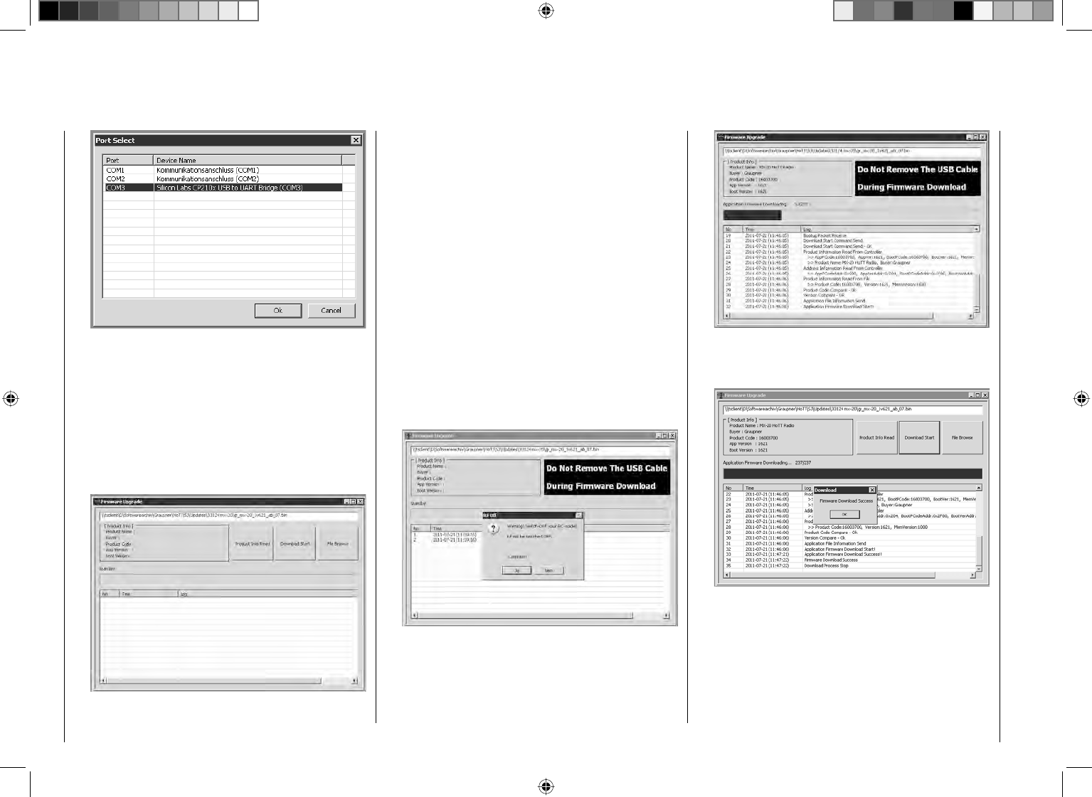
40 Putting the transmitter into operation
Now in the "Port select" window, select the COM
port connected to the USB interface. The correct port
can be recognized by its designation "Silicon Labs
CP210x USB to UART Bridge" in the "Device Name"
column. In the above example this would be the
"COM 3" port.
Now call up menu option "Firmware Upgrade" from
"Menu" or open the "Controller Menu" and click on
"Firmware Upgrade".
Click on the button labeled "File Browse" and select
the desired fi rmware update fi le with a ".bin" fi lename
extension from the "Open fi le" window.
Firmware fi les are product-specifi cally coded, i. e. if
you should accidentally select a fi le which does not
correspond to the product (e. g. receiver update fi le
instead of a transmitter update fi le), the "Product
code error" popup window will appear and the block
the update process from starting.
Now switch on the transmitter then start the
transmitter update by clicking on the "Download
Start" button.
After a brief period a warning will appear stating
that the transmitter's RF transmission will now be
interrupted and that, because of this, any receiver
system currently in operation should be switched off.
Switch off your receiver system if it is switched on
then click on "Yes".
This will start the actual update process. A progress
bar will begin to operate above a sequence of
running text lines.
Do not terminate the update process before the
progress bar has reached its right end and the
"Firmware Download Success" message appears.
Click on "OK". Subsequently switch off the transmitter
and disconnect the USB cable between the
transmitter and the PC or Laptop.
If the progress bar hangs up without showing any
further progress, close the program and repeat
the update process. Be sure to watch for any error
messages that may appear.

41
Your notes
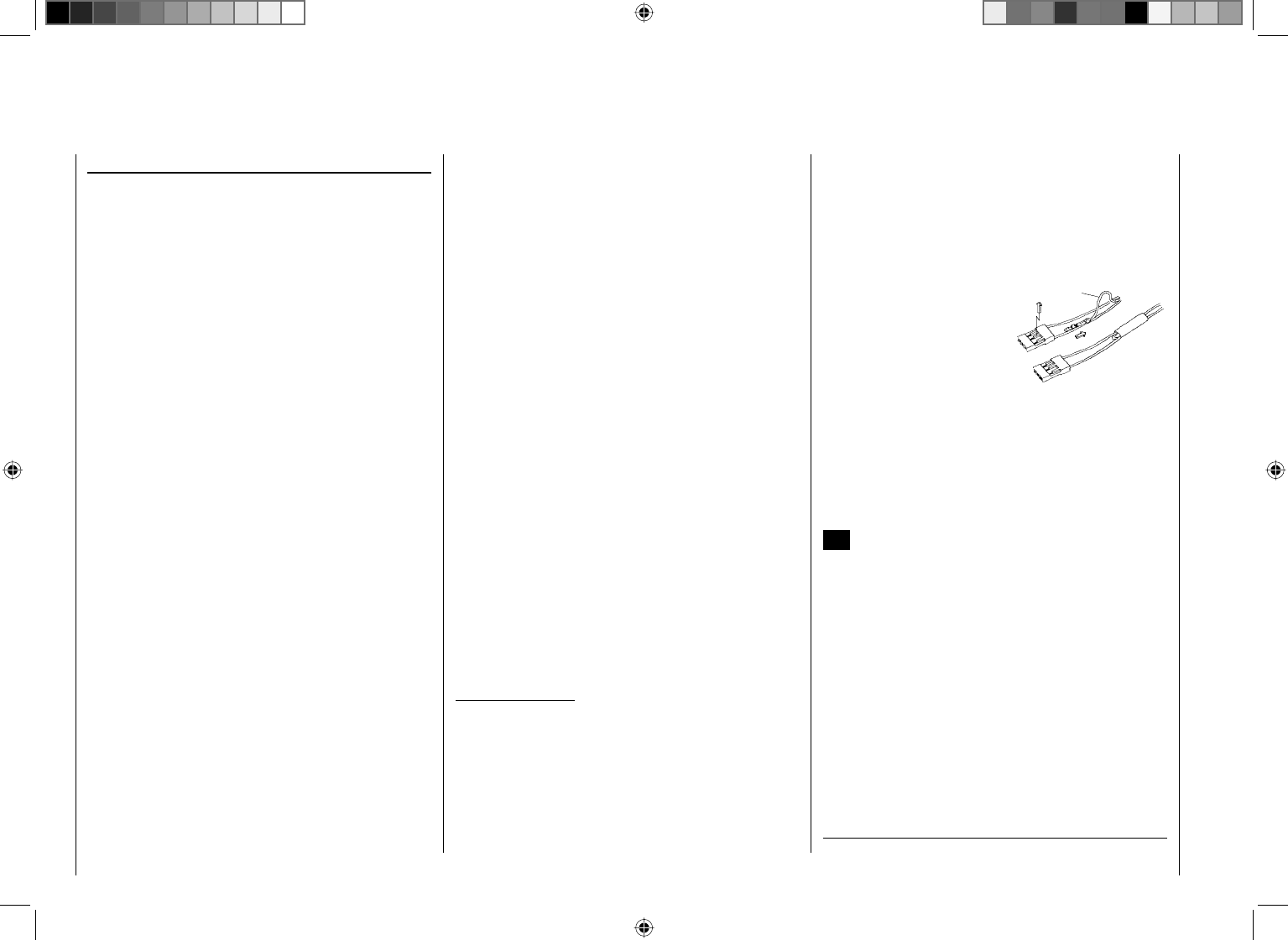
42 Putting the transmitter into operation
Receiver initialization
Preliminary remarks about the GR-24 receiver
Receiver system
The mc-32 HoTT remote control set includes a type
GR-24, 2.4 GHz bidirectional receiver for connecting up
to 12 servos.
After switching on this HoTT receiver, should "its"
transmitter not be within range or switched off, then the
receiver's red LED will illuminate continuously for about
1 s then begin to blink slowly. This indicates the receiver
has not (yet) established a link to a Graupner HoTT
transmitter. If a link has been established, the green
LED will illuminate continuously and the red LED will
extinguish.
In order to establish a link to the transmitter, the
Graupner HoTT receiver must fi rst be "bound" to
"its" particular model memory in "its" Graupner HoTT
transmitter. This procedure is known as "binding".
This "binding" linkage is only necessary once for each
receiver/model memory combination. Refer to pages
69 or 74. The "binding" procedure has been done at
the factory for model memory 1 of the units delivered
together as a set so this "binding" procedure will only
be necessary to link additional receivers or if a memory
location change becomes necessary (and – e. g. after a
change of transmitter – can be repeated anytime).
On-board voltage display
The current voltage of the receiver's power supply will
be shown in the right side of the transmitter's screen
if a telemetry link exists between the receiver and
transmitter.
Temperature warning
Should the receiver's temperature sink below an
adjustable threshold (default value -10 °C) or rise
above an adjustable threshold (default value +55 °C),
an acoustic warning will be issued by the transmitter in
the form of a uniform beep of about 1 s duration. The
aforementioned threshold limits are stored and adjusted
in the receiver.
Servo connections and polarity
Graupner HoTT receiver servo connections are
numbered. The connectors used are keyed against
polarity reversal. Pay attention to the small side profi les
when plugging in these connectors. Never use force.
The two outer connections, having designations "11+B-"
and "12+B-" are intended for the battery connections.
These two connections plus the servo's respective
connections can be combined into a single connector at
each end by way of a V or Y cable, Order No. 3936.11.
Do not reverse the polarity of this connection.
Reversed polarity could destroy the receiver and
devices attached to it.
The supply voltage is bussed across (i.e. common
for) all numbered connections. The function of every
individual channel is determined by the transmitter
used, not by the receiver. It is not only the throttle servo
connection which is different for every manufacturer and
model type. For example, in Graupner remote control
systems the throttle servo is on channel 1 for winged
aircraft and on channel 6 for helicopter models.
Concluding notices:
The signifi cantly greater servo resolution •
characteristic of the HoTT system produces a
noticeably fi rmer response behavior in comparison
to previous technology. Please take the time to
familiarize yourself with this sensitive behavior.
If you have a speed controller with integrated BEC* •
arranged in parallel with the receiver battery, its
positive pole (red cable) may to be removed from the
3-pole connector. Be sure to look for notices about
this in the instructions for the speed controller used.
Use a small screwdriver to carefully lift the
connector's middle latch slightly (1),
pull on the red wire to re-
move its connector pin
from the connector (2)
then put insulation tape
around the removed con-
nector pin to prevent pos-
sible short circuit condi-
tions (3).
red
1
23
Follow the installation instructions on page 46 for the
receiver, the receiver antenna and for mounting the
servo.
Reset
To execute a reset of the receiver, press and hold the
SET button on the receiver's top-side while switching the
power supply on. Once power is on, release the button
again.
If a receiver reset is done while the transmitter is
switched off or on a receiver which is not bound, the
receiver's LED will slowly blink red for about 2 or
3 seconds and then a binding procedure can be started
right away on the transmitter.
If reset is done on a bound receiver and the
corresponding model memory is active in the powered
on transmitter, the LED will illuminate in green after
a brief period as an indication that your transmitter/
receiver system is again ready for operation.
* Battery Elimination Circuit
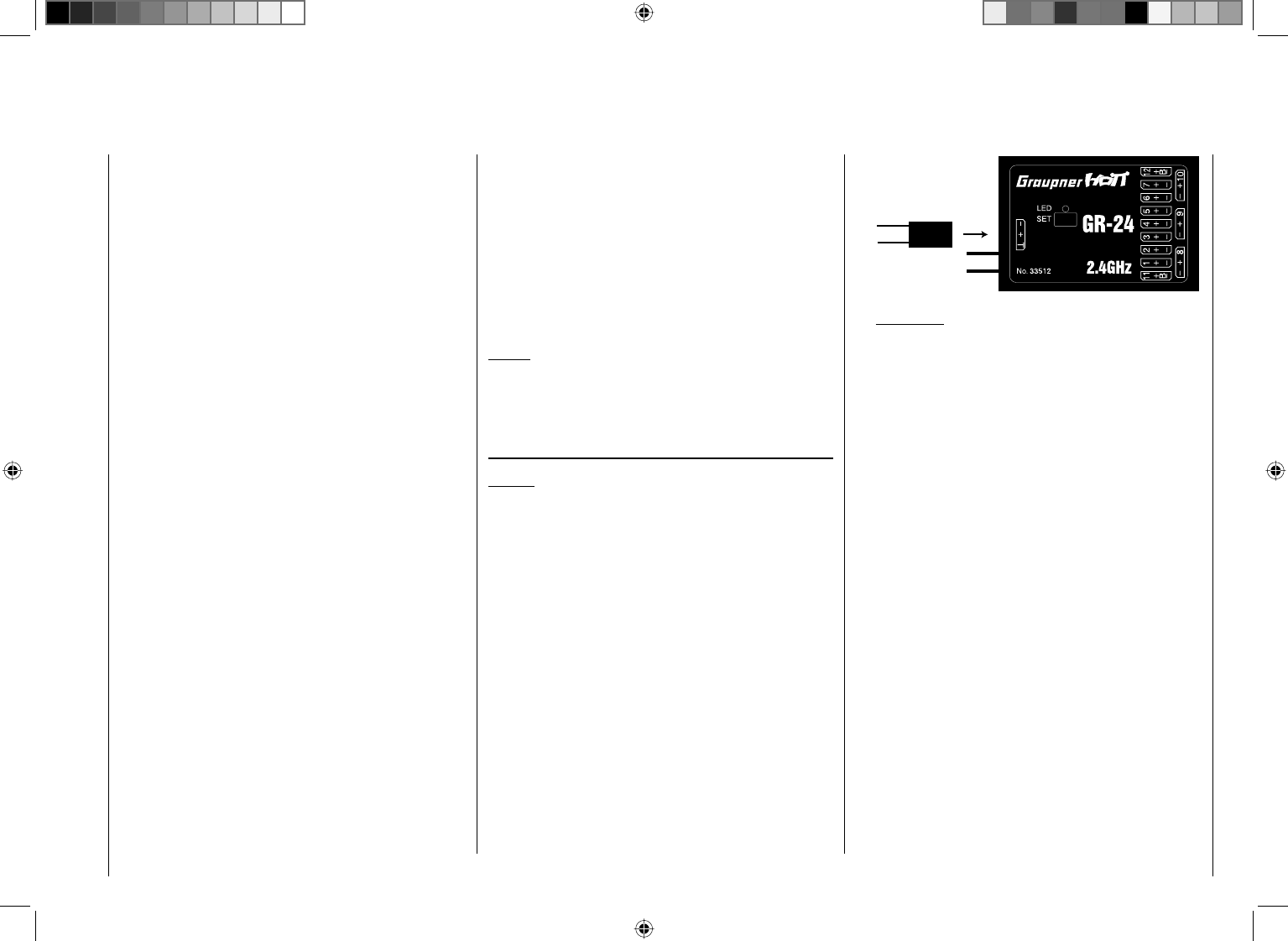
43
Putting the transmitter into operation
Please note the following:
A receiver RESET will cause ALL receiver settings
- except for binding information - to return to their
factory settings.
Therefore if a RESET is triggered unintentionally,
any custom settings that had been present in the
receiver before the reset will have to be established
again by way of the Telemetry menu.
A deliberate RESET is recommended, especially if
a receiver is to be "transferred" into another model.
This is a rather simple method to eliminate settings
which are no longer applicable.
Receiver fi rmware updates are made by way of the
connector located on the side of the receiver and
the help of a PC running under Windows XP, Vista or
Windows 7. The optional USB interface cable needed
for this is Order No. 7168.6 along with adapter cable,
Order No. 7168.6A. The programs and fi les also needed
can be found in Internet on the Graupner website at
www.graupner.de under the downloads for the particular
product.
Notice:
After registering your receiver at https://www.graupner.
de/de/service/produktregistrierung, you will automatically
receive notifi cation of future updates per email.
Updating receiver fi rmware
Notice:
Before any update procedure, be sure to check the
charged status of the receiver's battery. If necessary,
charge the battery before beginning with an update.
Installing drivers1.
If not already done, install the required driver
software for the USB interface, Order No. 7168.6, as
described on page 39.
Establishing a receiver / PC connection2.
Connect the USB interface cable, Order No. 7168.6,
via the adapter cable, Order No. 7168.6A, with the
"- + T" connector on the receiver. These connectors
are protected against polarity reversal so pay
attention to the small profi les on the sides of
connectors. Do not use brute force, these connectors
should latch in rather easily.
Receiver fi rmware updates
Adapter lead
Order No. 7168.6A
If a central red wire is present,
cut through it.
Attention:
If the adapter cable is still has wires for all
three poles, cut the red insulated wire for the
middle connector pin of the adapter cable, Order
No. 7168.6A.
Afterward, make the USB interface connection to the
PC or laptop by way of the delivered USB interface
cable (PC USB/mini-USB). If the USB interface is
connect properly, a red LED on the interface board
should illuminate for a few seconds.
If not already off, now switch the receiver off.
Firmware update utility program3.
On the PC, start the "Graupner_Firmware_Update_
Utility_VerX.XX.exe" program with a double-click.
This program is located among the fi les in the
"Firmware-Updater" folder. (At the time of printing for
this manual, this program's current version is 1.18
and it can be started without fi rst being installed.)
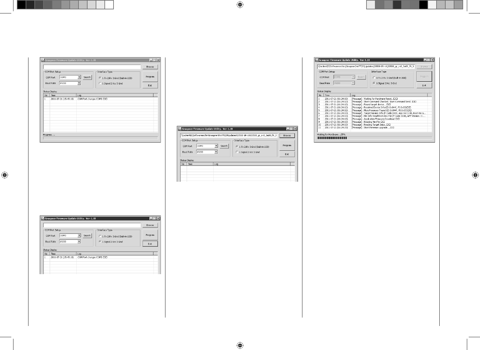
44 Putting the transmitter into operation
In the "COM Port Setup" group box, select the COM
port to which the USB interface is connected. If you
are not sure which selection is correct, press the
"Search" control, choose the connection labeled
"Silicon Labs CP210x USB to UART Bridge" from the
popup window and then activate "OK". The "Baud
Rate" setting should be "19200".
Afterwards, click on the "Signal 2:Vcc3:Gnd" radio
button in the "Interface Type" group box.
Now click on the control labeled "Browse" that is
located at the top right corner of the window. From
the "Open fi le" window which appears, select the
appropriate fi rmware update fi le for your receiver.
Such fi les always have the ".bin" fi lename extension.
Typically this fi le can be found in the folder whose
name is prefi xed with the order number of the
receiver to be updated. This folder should contain
the ZIP fi le that was downloaded and unpacked.
Its fi lename should also be prefi xed with the order
number of the receiver to be updated. For the
standard GR-12 receiver included in this set, the
folder would be designated "33512_12CH_RX". The
fi lename will appear in the corresponding window.
Firmware fi les are product-specifi cally coded, i. e. if
you should accidentally select a fi le which does not
correspond to the product (e. g. transmitter update
fi le instead of a receiver update fi le), the "Product
code error" popup window will appear and the block
the update process from starting.
Activate the control labeled "Program". Wait for the
progress bar to start. Depending on the speed of the
computer being used, this may take several seconds.
Now press and hold the receiver's SET button while
switching on the receiver's power supply. After a few
seconds the "Found target device …" message will
appear in the status display. Now you can release
the receiver's button. The actual fi rmware update
will begin autonomously after this message has
appeared.
However, if the receiver is not detected, the "Target
device ID not found" popup window will appear.
If this process terminates before reaching the 100 %
mark, switch off your receiver's power supply then try
to start the update process all over again. Do this by
performing the above steps again.
The status display and progress bar will show you
the progress of the fi rmware update. The update is
concluded when the text "Complete … 100 %" or
"Complete!!" appears in the bottom line of the status
display.
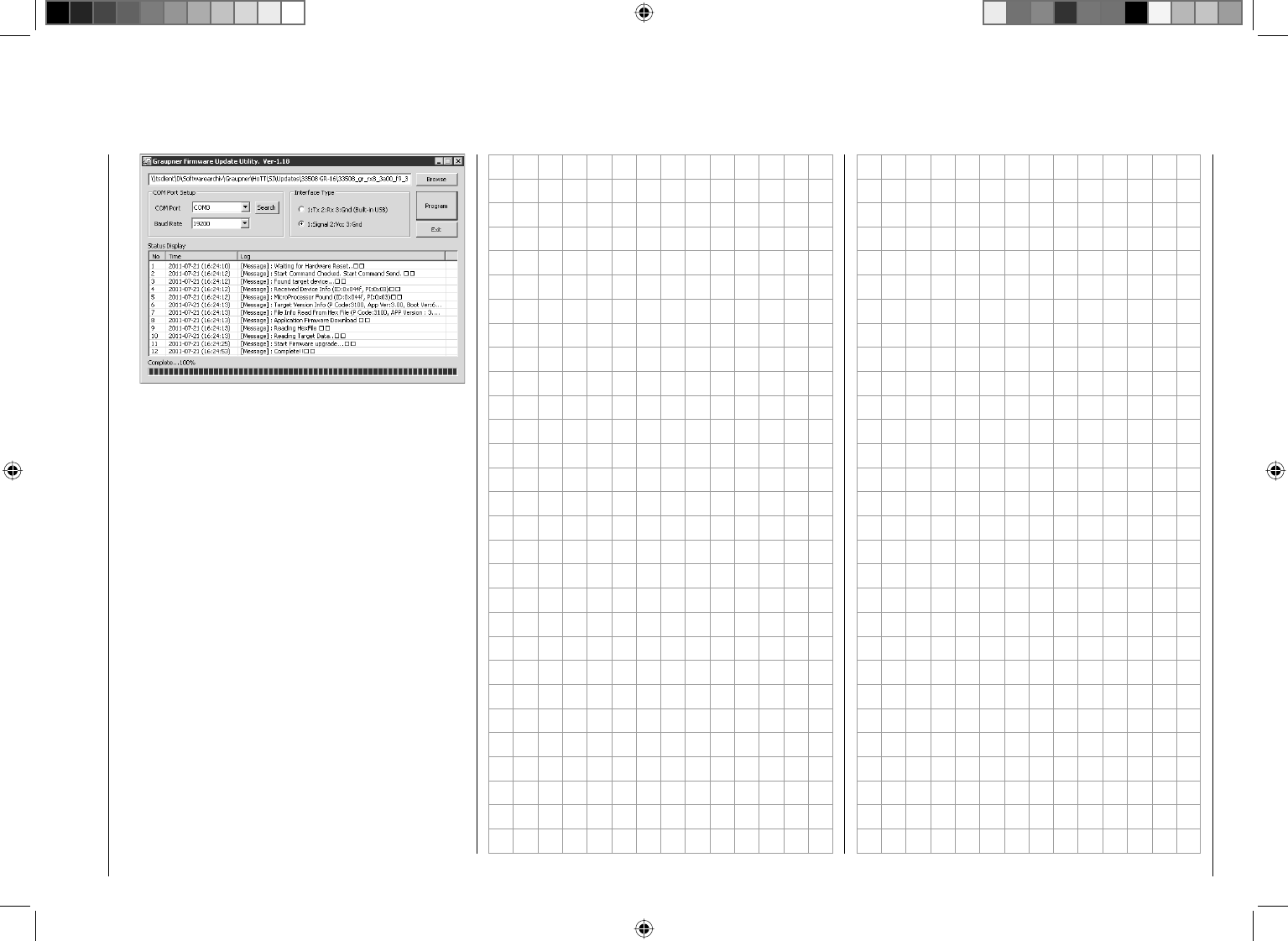
45
Putting the transmitter into operation
Both LEDs on the receiver will illuminate during the
update process. Upon successful conclusion of the
update process, the green LED will extinguish and
the red LED will begin to blink.
Switch off the receiver, remove the interface cable
and repeat the process for any other receivers you
have which must be updated.
Receiver initialization4.
Following a successful update process you MUST
perform a receiver initialization procedure before
using the receiver again. This is necessary for
reasons of safety.
Do this by pressing and holding the receiver's SET
button then switching the receiver's power supply
on. Now release the SET button again. When you
subsequently switch the receiver on again, the
receiver's green LED will illuminate continuously for
about 2 or 3 seconds. Except for binding information,
all other settings that may have been programmed
into the receiver will now be reset to factory defaults
and will have to be re-entered again if they are
needed.
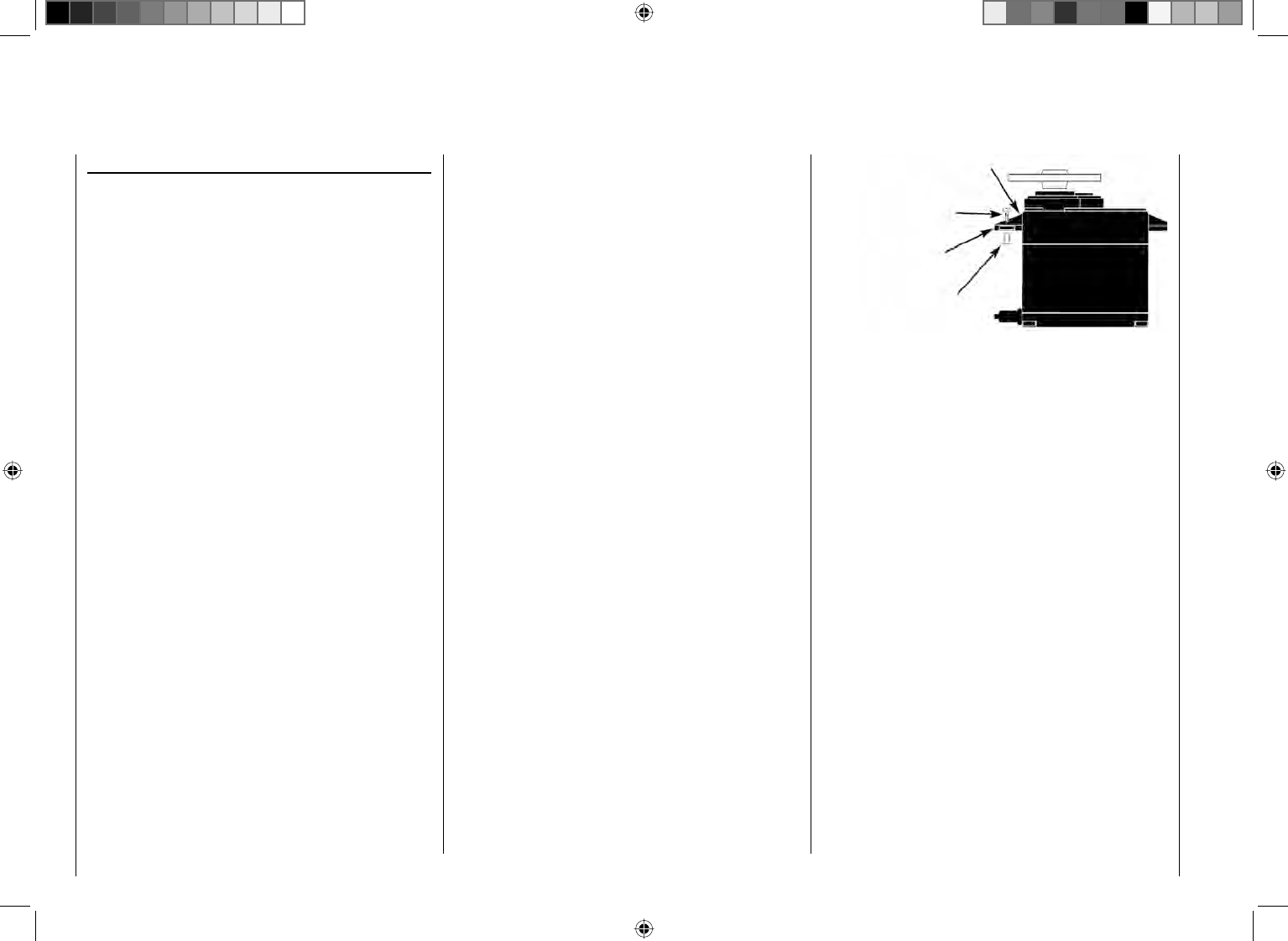
46 Installation notices
Servo mounting lug
Retaining screw
Rubber grommet
Tubular brass spacer
Servo arms must be free to move throughout their 4.
entire range of motion. Pay attention that there are no
objects which could hinder servo arm motion.
The sequence in which servos are connected to the
receiver depends on the type of model. Follow the
connection layouts provided for this on pages 57 and 59.
Also observe the safety notices provided on pages 4 … 9.
In order to prevent uncontrolled movements of servos
connected to the receiver during startup
always fi rst switch on the transmitter
and then the receiver
and when fi nished with operation
fi rst switch off the receiver
and then the transmitter.
When programming the transmitter, be sure that
electric motors cannot start running without control
or that a combustion motor equipped with automatic
starting cannot start up unintentionally. To be safe,
disconnect the receiver's drive battery or, in the case of
a combustion motor, disconnect the fuel supply.
The function of every individual channel is determined
by the transmitter used, not by the receiver. However,
channel assignments can be changed in the receiver
by programming done in the "Telemetry" menu.
Nevertheless, it is recommended this be done on the
transmitter side via the "Transmitter output" option, see
page 206.
Several notices and suggestions for installing
remote control components into a model are
provided below.
Wrap the receiver in a foam rubber pad that is at 1.
least 6 mm thick. Attach the foam rubber to the
receiver with rubber bands so it will be protected
against vibration and/or the jars of a hard landing.
All switches must be installed such that they are not 2.
affected by exhaust gasses or vibration. The switch
knob must be freely accessible over its entire range
of movement.
Mount servos on rubber bushes/spacers with hollow 3.
brass bearings to protect them from vibration. Do
not tighten the fastening screws down too tight as
this would negate the vibration protection to be
provided by the rubber bush/spacer. Only when servo
fastening screws are properly tightened will this
arrangement provide security and vibration protection
for your servos. The fi gure below shows how a servo
is mounted properly. The brass bearings are to be
pushed into the rubber bushes/spacers from below.
Installation notices
Receiver installation
Regardless of which Graupner receiver system you use,
the procedure is always the same.
Please pay attention that the receiver's antennas must
be mounted at least 5 cm away from all large metal
parts or any wiring that is not directly routed out of
the receiver itself. In addition to steel parts, this also
includes carbon fi ber parts, servos, fuel pumps and all
kinds of cables etc. Optimally the receiver should be
placed at a readily accessible location that is well away
from all other equipment. Under no circumstances may
servo cables be wrapped around the antennas or routed
close to it.
Please note that cables are subject to the acceleration
forces which occur during fl ight and these forces may
cause such cables, to shift in position. Therefore be
sure the cables in the vicinity of the antennas are not
able to move. Such moving cables can cause reception
disturbances.
Tests have shown that vertical (upright) antennas
provide the best results during wide-range fl ights. In the
case of diversity antennas (two antennas), the second
antenna should be oriented at a 90° angle to the fi rst
antenna.
The GR-24 HoTT receiver connections designated
"11+B" and "12+B" are intended for battery connections.
If necessary, an addition battery connection for a
servo can be made if a V or Y cable is used, Order
No. 3936.11. The power supply is bussed across all
numbered connections so it can be attached at any
of these 12 connectors. However, due to additional
voltage losses associated with the traverse connectors,
connections 8, 9 and 10 should not be used for
connecting the receiver's battery.
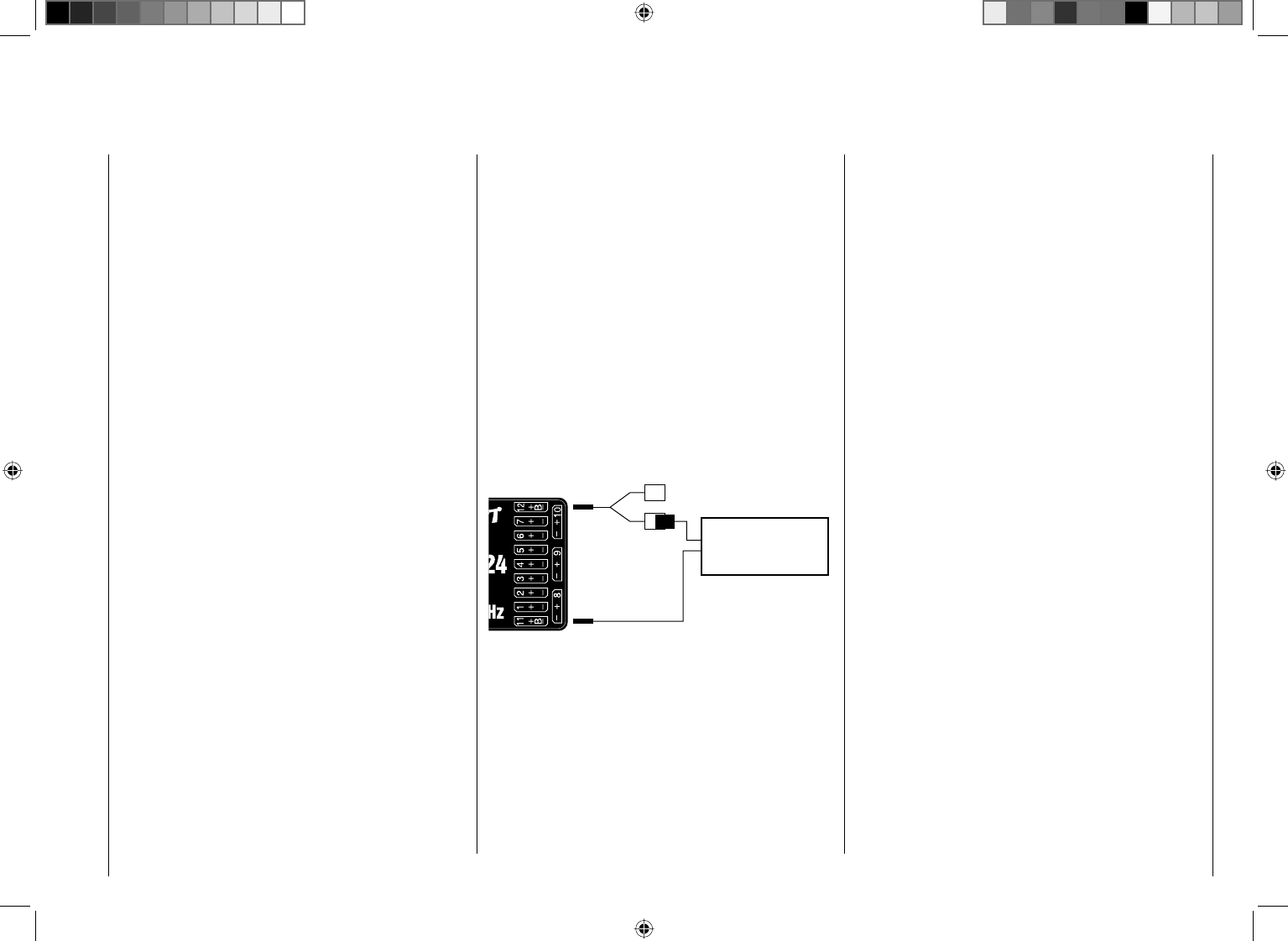
47
Installation notices
Receiver system power supply
Among other aspects, the safe operation of a model
depends on a reliable power supply. In the event that,
despite smooth operating rods, fully charged battery,
battery leads with adequate cross-section, minimum
contact resistances at connectors, etc., the transmitter
indicates repeated receiver voltage collapses or is
receiver voltage is generally too low; please give
attention to the following notices.
Give primary attention to fully charged batteries when
model operation is to be started. Be sure that the
contact surfaces of connectors and switches really are
low resistance. If necessary, measure the voltage drop
across installed switch cables when they are under
load because even new heavy-duty switches can cause
a voltage drop of up to 0.2 V. This value can increase
in contacts by factors as a consequence of aging and
oxidation. The constant vibrations and jarring also takes
its toll on contacts to produce a creeping increase of
contact resistance.
Servos present another possible problem source. Even
rather small servos like a Graupner/JR DS-281 can draw
up to 0.75 A of current when it is blocks under load. Just
four of these servos in a "foam" model can therefore load
down the on-board power supply by as much as 3 A …
Therefore you should choose a power supply which will
not break down under greater loads but rather always
deliver suffi cient voltage. To "calculate" necessary
battery capacity you should always fi gure on at least
350 mAh for every analog servo and at least 500 mAh
for every digital servo.
For example, from this point of view a battery with
1400 mAh would be the absolute minimum to power
a receiver system with a total of 4 analog servos. But
be sure to also consider the receiver itself into the
calculation because its bidirectional functionality will
draw about 70 mA of current too.
It is also a good practice to connect the receiver to
its power source with two cables rather than just one.
Cable "1" could be connected to the "12+B" receiver
connector as is usual and cable "2" could be connected
to the opposite end of the row at the connector labeled
"11+B". For example by using two power supply cables
to connect one switch or voltage regulator to the
receiver. Just use a V or Y cable, Order No. 3936.11
to accomplish this (see fi gure) if you should need one
or both of the receiver's connectors to attach a servo,
speed controller, etc. This double-connection technique
to switches and speed controllers not only reduces the
risk of a cable break but also ensures a more uniform
supply of power to the connected servo.
Aux. function
Y-lead
Order No. 3936.11
PRX stabilised
receiver power supply
Order No. 4136
NiMH 4-cell battery packs
In compliance with the aforementioned conditions, your
Graupner HoTT receiver system can be readily operated
with traditional 4-cell battery packs as long as the packs
have adequate capacity and voltage level.
NiMH 5-cell battery packs
Five-cell battery packs offer a greater voltage tolerance
than do 4-cell packs.
However, be aware that not every servo available on
the market is able to tolerate the voltage level output by
a 5-cell pack over the long term, this is particularly true
when the battery pack is freshly charged. Some of these
servos react to this with a noticeable "grinding" sound.
Therefore pay attention to the specifi cations of the
servos you use before making a choice for a 5-cell
battery pack..
LiFe 6.6 V batteries with 2 cells
From a contemporary perspective, these new cells are
the very best choice.
LiFe cells are also available in hard plastic casings to
protect them from mechanical damage. Like LiPo cells,
LiFe cells can be quick charged in suitable chargers and
they are comparatively robust.
This type of secondary cell battery is also rated for a
signifi cantly greater number of charge/discharge cycles
than, for example, LiPo batteries The nominal 6.6 V
output of a 2-cell LiFe battery pack does not present
a problem for either Graupner HoTT receivers nor for
those servos, speed controllers, gyros and other devices
which have been specifi cally approved for operation in
this – higher – voltage range. Please note however
that practically all servos, speed controllers, gyros
and other devices built in the past and most such
devices currently still offered on the market have
only a permissible voltage range of 4.8 to 6 V. Use
of these batteries in conjunction with these devices
demand use of a stabilized voltage regulator, e. g. the
PRX, Order No. 4136, see appendix. Otherwise there is
danger that attached devices will incur damage within a
short period of time.
LiPo 2-cell packs
For a given capacity, LiPo batteries are lighter than,
48 Installation notices
for example, NiMH batteries. LiPo batteries are also
available in hard plastic casings to protect them from
mechanical damage.
The comparatively high nominal voltage, 7.4 V, for a
2-cell LiPo pack does not present a problem for either
Graupner HoTT receivers nor for those servos, speed
controllers, gyros and other devices which have been
specifi cally approved for operation in this – higher –
voltage range. Please note however that practically
all servos, speed controllers, gyros and other
devices built in the past and most such devices
currently still offered on the market have only a
permissible voltage range of 4.8 to 6 V. Use of these
batteries in conjunction with these devices demand use
of a stabilized voltage regulator, e. g. the PRX, Order
No. 4136, see appendix. Otherwise there is danger that
attached devices will incur damage within a short period
of time.

49
Your notes

50 Term defi nitions
Term defi nitions
Control function, control, function input, control channel, mixer, switch, control switch, fi xed switch
To make use of this mc-32 HoTT manual easier, a
number of the terms used repeatedly throughout this
manual have been defi ned below.
Control function
A "control function" is a signal intended to affect a
given control action – initially independent of its signal
course in the – . For example, this could be for throttle,
ruder or aileron in a winged aircraft or pitch, roll or
crow for a helicopter. A control function signal can
be applied directly over a single control channel or
also through a mixer and then applied over multiple
control channels. A typical example of multiple control
channels is separately operated aileron servos or the
use of two roll or crow servos in helicopters. The control
function explicitly includes the infl uence of the control's
mechanical travel on the respective servo.
Control
"Controls" include all operating elements on the
transmitter, which are directly activated by the pilot,
that impose an effect on servos, speed controllers etc.
connected to the receiver. This includes:
both joysticks (control functions 1 through 4), even •
though these four control functions can be freely
swapped around for both model types ("winged
aircraft" and "helicopters") by use of software "Mode"
settings, e. g. throttle left or right. The dual-axis
function for throttle/airbrake is often referred to as the
C1 control (channel 1).
the three • proportional rotary controls, which are
CTRL 6, 7 + 8,
the switches, SW 4/5 and 6/7, which are CTRL 9 and 10,•
switches SW 1 … 3 as well as 8 and 9, if assigned to •
a control channel via the "Transm. controls" menu.
The proportional operating elements produce a direct
effect on servos which is commensurate with the
control's position whereas switch modules can only
effect a two or three increment change.
Function input
This is an imaginary point in the signal path and must
not be considered the same as the point on the circuit
board where the transmitter control is connected.
The choice of "controls arrangement" and settings
in the "Transm. controls" menu have their effect
"downstream" of this imaginary point of connection.
Thus differences between the physical control's number
and the number of the downstream control channel can
indeed emerge.
Control channel
From the point at which a signal contains all control
information necessary for a particular servo – whether
directly from the physical control or indirectly by way of a
mixer – the term "control channel" is used. This signal is
only yet to be infl uenced by settings made in the "Servo
adjustment" menu and the "Transmitter output" menu
before it leaves the transmitter's RF module.
Once it arrives at the receiver, this signal may still
be modifi ed by settings made in the telemetry menu
before fi nally being applied as a control quantity for the
respective servo.
Mixers
The transmitter's software contains diverse mixer
functions. These can be used to apply one control
function to multiple servos or, conversely, to apply
multiple control functions to a single servo. Please look
over the numerous mixer functions in the text beginning
on page 145 of this manual.
Switches
The three standard 2-position switches, SW 2, 3 and
8, the two 3-position switches, SW 4/5 and 6/7, as well
as both pushbutton switches, SW 1 and 9, can also be
combined with control programming. However, these
switches are generally intended for switching program
options, e. g. to start and stop timers, to switch mixers
on and off, or as a teacher/pupil switchover, etc. Each
of these switches can be assigned any number of
functions.
Appropriate examples are detailed in the manual.
Control switches
Since it is very practical to have some functions
automatically switched on or off for a certain control's
position (e. g. switch on/off of a stopwatch for acquisition
of model run time, automatic extension of spoilers and
other possibilities), four control switches have been
integrated into mc-32 HoTT software.
These software switches, designated "G1 … G4", are
triggered by setting a switch-point along the physical
control's course of travel. This "trigger setting" is simply
defi ned with the press of a button. The switching
action can be correlated to the physical control's travel
direction by software.
Of course control switches can also be freely combined
with the aforementioned physical switches to solve even
more complex problems.
There is a series of instructive examples which make
this programming child's play. Learn about this by taking
advantage of the programming examples beginning on
page 226.

51
Term defi nitions
Fixed switches FXI and FX
This type of switch turns a function permanently on,
e. b. timers (closed fi xed switch) or off (open fi xed
switch) or they can provide a fi xed input signal for a
control function, e. g. FXI = + 100 % and FX = -100 %.
For example, in fl ight phase programming, these fi xed
switches can be used to switch a servo or speed
controller between two settings.
52 Physical control, switch and control switch assignments
Physical control, switch and control switch assignments
Principle procedure
The mc-32 Hott system exhibits maximum fl exibility
when it comes to assigning standard equipment
operating elements to specifi c functions.
Since the assignment of controls and switches is done
in the same way, even though different menus may be
involved, it is appropriate at this point to explain the
fundamental programming technique so that users can
concentrate on the particular contents when reading the
detailed menu descriptions.
Physical control and switch assignments
The "Control adjust" menu can be used to assign
transmitter inputs 5 … 12 to operate servos, both from
any given joystick direction (K1 … K4) as well as to
assign any other physical control designated "CTRL"
or switch designated "SW". After tapping on the center
SET key in the right key pad, the screen shown below
will appear.
Move desired switch
or control adj.
Now simply activate the desired control (joystick 1 … 4,
CTRL 6 … 10 or switch 1 … 3, 8 or 9).
Notice:
Rotary controls, CTRL 6 … 8, will not be recognized
until they "detent". Therefore these controls can be
turned back and forth until the correct assignment is
shown in the screen. If adjustment travel is insuffi cient,
activate the control in the other direction.
On the other hand, if you wish to assign a control in the
"Control switch" menu, page 119, the "activate desired
control" message will appear.
push desired switch
into position ON
Important notice:
Controls to be assigned (particularly CON TROL 6 …
10) MUST be pre-assigned in the "Control adjust"
menu to one of the inputs 5 through 12!
Control assignment
Wherever programming permits a switch to be assigned,
a switch symbol will appear in the screen's bottom
display line.
Use the arrow keys in the left or right touch pad to select
the appropriate column.
How to assign a switch
Briefl y press the 1. SET-T key in the right touch pad.
The message shown below will appear in the screen.
Move desired switch
to ON position
(ext. switch: SET )
Now it is only necessary to put the selected switch 2.
into the desired "ON" position or, as described at the
right in "Assignment of external switches", to select
a switch from the list of "External switches". This
concludes the assignment. The switch symbol to the
right of the switch's number indicates the current
state of the particular switch.
Since CTRL 9 and 10 as well as the 3-position
switches, SW 4/5 and 6/7, are not only usable as
controls but also function as pure switches, there is a
total of 9 switches ("SW 1 … 9") available for use as
desired.
Changing switch action
If the activation of a switch is to result in the opposite
action, put the switch or joystick in the desired OFF
position, again activate the switch assignment and
reassign the switch again so it will respond with the
desired action.
Clear switch
A switch which has been assigned as described under
point 1 can be cleared by simultaneously pressing the
cd or ef key combination briefl y in the right key pad
(CLEAR).
Assignment from the "external switch" list
Those menus in which the message …
Move desired switch
to ON position
(ext. switch: SET )
… appears for switches designated with "SW" can be
used to assign so-called "external switches.
Do this by confi rming the message text with the SET
key. A new window will appear with a list of the four
control switches "C1 … C4", followed by two so-called
"FX" fi xed switches and the four inverted switches "C1i...
C4i".
53
Physical control, switch and control switch assignments
Control/fix sw
C1 C2 C3 C4 FX
FXi C1i C2i C3i C4i
Use the arrow keys in the left or right key pad to select
the desired switch then assign it with a brief tap on the
center SET key of the right touch pad.
Notices:
The two FX switches turn a function on "FXI" or off •
"FX " permanently.
All other switches mentioned can have multiple •
assignments. Pay attention that you do not
UNINTENTIONALLY assign reciprocally confl icting
functions to a single switch. If necessary, note down
the given switch functions.
Application examples:
Shut-off of an on-board glow plug heater upon •
underrun or overrun of an idle threshold point
programmed for the C1 joystick. In this case the glow
plug heater switch is controlled by a transmitter mixer.
Automatic switch on/off of the timer to measure pure •
"fl ight time" for a helicopter by way of a control switch
on the throttle limiter.
Automatic switch off of the "AI • ¼ Rud" when brake
fl aps are extended, for example to adapt the roll of
a model to the ground when making a landing on a
slope without inducing a change of fl ight direction
due to infl uence on the rudder.
Extending landing fl aps with elevator trim adjustment •
during a landing as soon as the throttle stick is
moved beyond its switch point.
Switch on/off of the timer for measuring the operating •
time of electric motors.
The control switches, freely programmable in the
"Control switch" menu, can be incorporated into
switch programming, i. e. assigned to a function instead
of a "normal" switch. At those program locations
where switches can be assigned you always have the
opportunity to assign one of the control switches, C1...
C4, instead of a physical switch by selecting one of
these out of the list of "external switches".
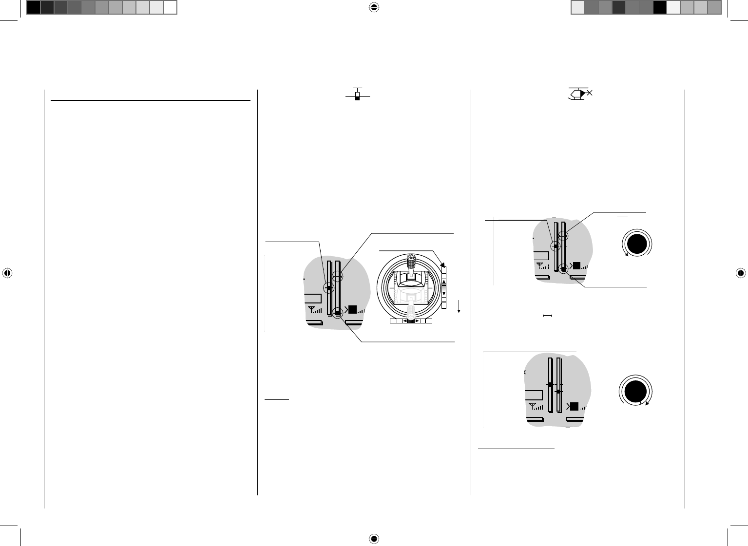
54 Digital trim
Digital trim
Functional description and description of C1 cut-off
Digital trim with visible and audible indicators
Both joysticks are equipped for digital trimming. When
you give the trim lever a brief push (one "click"), the
neutral position of the associated joystick channel
changes by one increment. If you hold the trim lever in
one direction, the trim value changes continuously in the
corresponding direction with increasing speed.
These changes can be made "audible" by way of different
frequency tones. This makes fi nding the mid-point during
fl ight easy, without looking at the screen. When the mid-
point is overrun, a brief pause will be inserted.
Current trim values are automatically stored when a
model memory change is made. Furthermore, digital trim
exercises fl ight phase specifi c control within a memory
location (except for throttle/brake fl aps trim) – the so-
called "C1" (channel 1) control function –.
This C1 trim includes yet another special function
for winged aircraft and helicopter models, it allows
the carburetor's idle setting to easily be found for a
combustion motor.
Since the trim functions described in these instructions
are only effective in the direction "Motor off", the
presentation in the screen of your transmitter may only
change with respect to individual throttle or Pitch-min
positioning of the C1 joystick in the "forward" or "back"
direction, such as throttle/pitch "left stick" or "right stick".
The illustrations in these instructions are always based
on "Throttle/Pitch right" for both types of models and
"Throttle back" for winged aircraft and helicopters.
2. Helicopter models
In addition to the "Cut-off trim" function described
below in "Winged aircraft models", C1 trimming also
has another characteristic which is made possible by
combining it with a so-called "Throttle limit" function see
page 104. As long as the throttle limit control remains in
the "left" half of its travel path, i. e. in the startup range,
C1 trimming acts on the throttle servo as idle trim and the
indication for idle trim is visible in the screen's display.
GRAUBELE
#01
3:33h
stop
flt
K78
0:00
0:00
RX0.0V
5.2V
Last idle position
2.4
M
motor OFF position
CTRL 6
Throttle limit control
Current trim position
Trim at
However, in contrast to winged aircraft models, the
position indicator ( ) will be hidden and any preset idle
position will be deleted when the throttle limit control is
in the "right" half of its travel path.
GRAUBELE
#01
3:33h
Stop
Flt
K78
0:00
0:00
RX0.0V
5.2V
M2.4CTRL 6
Throttle limit control
Notice for helicopters:
C1 trimming affects only the throttle servo, not the pitch
servo. Notice also that the helicopter throttle servo must
be connected to receiver output 6, see receiver layout
on page 59.
1. Winged models
C1 trimming has a special cut-off trim function intended
especially for combustion motors. This cut-off trim
function is confi gured as follows. First put the motor into
a safe idle speed.
Now if you push C1 trim in a single motion toward its
"Motor cut-off" direction until it is in its furthest travel
position then an additional end-position marker will
remain in the display. When the motor is restarted you
can again immediately set the last idle speed with a
single movement in the direction of "more gas".
GRAUBELE
#01
3:33h
Stop
Flt
K78
0:00
0:00
RX0.0V
5.2V
Current
trim position
Current trim position
2.4
Ch 1 trim lever
Idle direction
M
Trim at motor OFF position
This cut-off trim will be deactivated when "None" is
entered on the "Motor at C1" line of the "Model Type"
menu, see page 82.
Notice:
Since this trim function is only effective in the "Motor
off" direction, the display illustrated above will change
appropriately if the C1 joystick's control direction for
minimum throttle is changed from "back" to "front" (on
which the above illustration is based) in the "Motor at
C1" line of the "Basic Settings" menu.

55
Your notes
56 Winged models
Winged models
Convenient support is provided for up to four aileron
servos and four fl ap servos on normal models or, for
V tail and fl ying wing/delta models, up to two aileron/
elevator servos plus four fl ap servos.
The majority of motorized and glider models belong to
the tail unit type "normal" and are equipped with one
servo each for elevator, rudder and ailerons in addition
to a motor throttle or electronic speed controller (or for
brake fl aps in the case of a glider model). Beyond this,
tail unit type "2HRSv3+8" permits the connection of two
elevator servos to receiver outputs 3 and 8.
If ailerons, and conditionally the fl aps, are each actuated
with two separate servos then settings can be made for
differentiated control of all aileron and fl ap pairs in the
"Wing mixers" menu, i.e. settings for downward ruder
throw independent of upward throw.
Finally, the position of fl aps can be controlled by a
control out of group CTRL 6 … 10. Alternatively, there
is a phase-dependent trim function available for fl aps,
ailerons and elevators in the "Phase trim" menu.
The "V tail unit" is to be selected from the "Model
type" menu if the model has a V tail unit instead of
a normal tail unit. This V tail unit selection provides
coupled elevator and ruder control functions for both
tail fl aps – each controlled by a separate servo – which
handles both elevator and ruder functionality.
For delta and fl ying wing aircraft models, aileron and
elevator functionality is affected by way of a common
rudder fl ap on the trailing edge of each side (right and
left) of the wing. The program contains appropriate mixer
functions for both servos.
Up to 7 fl ight phases can be programmed into each of
the 24 model memory locations.
Except for C1 trim, digital trim will be stored on a
fl ight-phase basis. C1 trim permits easy location of a
carburetor idle setting.
Two timers are always available for fl ight operation. The
transmitter operating time expired since the last battery
charge is also displayed.
All transmitter controls (CTRL) and switches (SW) can
be assigned in the "Control adjust" menu to inputs 5
… 12 with almost no restrictions.
The "Dual Rate" and "Exponential" functions for ailerons,
rudder and elevators are separately programmable and
each are convertible between the two variations on a
specifi c fl ight-phase basis.
In addition to 8 freely allocatable linear mixers, 4
curve mixers ("Free mixers" menu) and 4 dual mixers
("Dual mixer" menu), there are also fl ight-phase
dependent 6-point curves for control channel 1 (throttle/
brake), see "Channel 1 curve" menu).
Depending on the number of wing servos, fi xed-
defi nition mix and coupling functions can be selected
from a list in the "Wing mixers" menu.
Multi-fl ap menu: control of fl aps as ailerons, the •
infl uence aileron trim on fl aps controlled as ailerons,
fl ap differentiation, fl ap function throw magnitude for
all aileron and fl ap pairs, ailerons controlled as fl aps,
elevator mixer ¼ fl aps
Brake settings: butterfl y, differential reduction, •
elevator curves
aileron • ¼ rudder mixer
fl aps •¼ elevator mixer
E
l
e
v
a
t
o
r
F
l
a
p
F
l
a
p
E
l
e
v
a
t
o
r
F
l
a
p
A
i
l
e
r
o
n
A
i
l
e
r
o
n
F
l
a
p
A
i
l
e
r
o
n
R
u
d
d
e
r
E
l
e
v
a
t
o
r
A
i
l
e
r
o
n
left
right
E
l
e
v
a
t
o
r
F
l
a
p
F
l
a
p
E
l
e
v
a
t
o
r
A
i
l
e
r
o
n
R
u
d
d
e
r
A
i
l
e
r
o
n
F
l
a
p
Airbrake Flap
Airbrake Elevator
Airbrake-Function 1
left
right
Rudder/Elevator
V-Tail
AI
FL
FL
AI
Brake FL, FL2
Brake Elevator
Brake AI, AI2
AI
FL
FL2
AI
FL
FL2
AI2
F
L
J
A
I
F
L
I
A
I
E
L
I
F
L
RU I AI
EL I AI
E
L
J
F
L
AI2
A
I
J
F
L
A
I
I
F
L
57
Winged models
Installation notices
Servos MUST be connected to the receiver in the
sequence illustrated here.
Outputs which are not needed are simply left empty.
Also be sure to follow the notices on the next pages.
Winged aircraft with and without motor, having up to
4 aileron servos and up to 4 fl ap servos …
… and tail plane type "normal" or "2 elevator
servos"
Receiver power supply
Free or left aileron 2 or aux. function
Free or right aileron 2 or aux. function
Rudder
Aileron or left aileron
Elevator or 1st elevator
Free or 2nd elevator or aux. function
Receiver power supply
Airbrake or throttle servo
or speed controller (electric motor)
Right aileron or aux. function
Flap or left flap
Right flap or free or aux. function
Free or left flap 2 or aux. function
Free or right flap 2 or aux. function
… and tail plane type "V tail unit"
Receiver power supply
Free or aux. function
Free or aux. function
Aileron or left aileron
Free or aux. function
Receiver power supply
Airbrake or throttle servo
or speed controller (electric motor)
Right aileron or aux. function
Flap or left flap
Right flap or free or aux. function
Free or left flap 2 or aux. function
Free or right flap 2 or aux. function
Left rudder / elevator
Right rudder / elevator
Delta/fl ying wing aircraft models with and without
motor having up to two aileron/elevator servos and
up to 2 fl ap/elevator servos
Receiver power supply
Free or aux. function
Free or aux. function
Right elevon
Right elevon
Free or aux. function
Receiver power supply
Airbrake or throttle servo
or speed controller (electric motor)
Free or aux. function
Free or left flap / elevator
Free or right flap / elevator
Free or aux. function or left flap 2 / elevato
Free or aux. function or right flap 2 / eleva
t
Free or rudder
Because of orientation differences for installed servos
and their rudder linkages, the actuating direction of
some servos may be initially backward. The table below
provides remedies.
Model
type
Servo actuation
direction
wrong
Remedy
V tail Rudder and
elevator reversed
Reverse the polarity of
servos 3 & 4 in the "Servo
adjustment" menu
Rudder correct,
elevators reversed
Swap the connections
for servos 3 & 4 on the
receiver
Elevators correct,
rudder reversed
Reverse the polarity of
servos 3 & 4 in the "Servo
adjustment" menu AND
on the receiver
Delta,
fl ying
wing
Elevator and
aileron reversed
Reverse the polarity of
servos 2 & 3 in the "Servo
adjustment" menu
Elevator correct,
aileron reversed
Reverse the polarity of
servos 2 & 3 in the "Servo
adjustment" menu AND
on the receiver
Aileron correct,
elevators reversed
Swap servos 2 & 3 at the
receiver
All "program descriptions" for menus relevant to a
winged aircraft model are marked with a winged aircraft
symbol …
… so only these menus need to be dealt with to program
a winged aircraft model.
58 Helicopter models
Helicopter models
Collective
Pitch Curve
Swashplate
Rotation
Roll Throttle
Pitch-Axis Throttle
Channel 1 Throttle
Roll Tail Rotor
Pitch-Axis Tail Rotor
Channel 1 Tail Rotor
C
h
a
n
n
e
l
1
T
a
i
l
R
o
t
o
r
T
a
i
l
R
o
t
o
r
T
h
r
o
t
t
l
e
The advanced developments incorporated into the
transmitter as well as those now in helicopter models
and their components like gyros, speed regulators, rotor
blades, etc. make it possible to master a helicopter even
in 3D acrobatic fl ight. On the other hand, a beginner
needs only a few settings to get started with hovered
fl ight training and then can take advantage of mc-32
HoTT features, step-by-step, with increasing expertise.
The mc-32 HoTT program can operate all
conventional helicopters having 1 … 4 servos for pitch
control.
Six fl ight phases plus autorotation are available within
a model memory, see menus "Control adjust", "Phase
settings" and "Phase assignment".
As with winged aircraft, here too, in addition to the basic
screen's standard timers there are additional timers
as well as a lap counter with fl ight-phase-dependent
stopwatch functionality which are available for selection
(menus "Timers (general)" and "Fl. phase timers").
Except for pitch/throttle trimming, digital trimming can be
stored as "global" for all fl ight phases or as "fl ight phase
specifi c". C1 trim permits easy location of an idle setting.
The control assignments of inputs 5... 12 can be made
common to every fl ight phase or separate ("Control
adjust" menu).
A fl ight phase copy function is helpful during fl ight trials
("Copy / Erase" menu).
"Dual Rate" and "Exponential" functions can be coupled
for roll, nick and tail rotor and programmable in two
variations in every fl ight phase.
There are 8 freely assignable linear mixers. There are
also 4 curve mixers that can be programed and these
can also be switched on or off, depending on the fl ight
phase, in the "Mix active/Phase" menu. Beyond this,
there are also 4 dual mixers available.
Available in the "Helicopter mixer" menu are fl ight-
phase-dependent 6-point curves for pitch, throttle and
tail rotor mixer non-linear characteristics as well as two
independent swashplate mixers each for roll and nick.
Independent of this, the control curve of the channel
1 joystick can be defi ned with up to 6 points in every
fl ight phase. The beginner will initially only adapt the
hover fl ight point to the control middle for the non-linear
characteristics.
Pre-programmed mixers in the "Helicopter mixer"
menu:
Pitch curve (6-point curve)1.
Channel 1 2. ¼ Throttle (6-point curve)
Channel 1 3. ¼ Tail rotor (6-point curve)
Tail rotor 4. ¼ Throttle
Roll 5. ¼ Throttle
Roll 6. ¼ Tail rotor
Nick 7. ¼ Throttle
Nick 8. ¼ Tail rotor
Gyro suppress9.
Swash rotation10.
Swash limiter11.
The "Throttle limit" function (input 12 in the "Control
adjust" menu) allows the motor to be started in any
fl ight phase. Control 6 – the proportional rotation control,
CTRL 6 top left – is assigned to input 12 by default. This
"throttle limiter" establishes – depending on its given
position – the maximum possible carburetor position.
This makes it possible for the motor to be controlled in
the idle range, if necessary even by the proportional
regulator. The throttle curves become effective only
when the proportional regulator is pushed toward the full
throttle direction.
59
Helicopter models
Notice for those transitioning from older Graupner
systems:
In comparison to previous receiver layouts, servo
connector 1 (pitch servo) and servo connector 6
(throttle servo) have exchanged places. Servos must
be connected to receiver outputs as illustrated at the
right in the bottom fi gure. Outputs which are not used
are simply left empty. More details about respective
swashplate types can be found on page 86 in the
"Basic settings" menu.
Installation notices
Servos MUST be connected to the receiver in the
sequence illustrated here.
Outputs which are not used are simply left empty.
Also be sure to follow the notices on the next pages.
Notice:
A speed regulator is also to be connected to receiver
output "6" in order to take full advantage of the throttle
limiter's convenience and safety features, see text
beginning on page 104. See page 169 about this.
Receiver layout for helicopter models …
… with 1 to 3 swashplate servos
Receiver power supply
Free or aux. function
Free or aux. function
Tail rotor servo (gyro system)
Roll 1 servo
Pitch-axis 1 servo
Free or speed governor or aux. function
Receiver power supply
Collective pitch or roll 2 or
Pitch-axis 2 servo
Free or aux. function
Throttle servo or speed controller
Gyro gain
Free or aux. function
Free or aux. function
… with 4 swashplate servos
Receiver power supply
Free or aux. function
Free or aux. function
Tail rotor servo (gyro system)
Roll 1 servo
Pitch-axis 1 servo
Free or speed governor or aux. function
Receiver power supply
Roll 2 servo
Pitch-axis 2 servo
Throttle servo or speed controller
Gyro gain
Free or aux. function
Free or aux. function
All menus relevant to helicopter models are marked
in the "program descriptions" section with a helicopter
symbol …
… so only these menus need to be dealt with to program
a helicopter model.
60 Detail program description - Loading a new memory location
Anyone who has worked through to this part of
the manual has certainly already tried out a bit of
programming. Nevertheless a detailed description of
every menu should not be left out.
This section begins with the loading of a "free" memory
location, a procedure which would be performed if a new
model was being "programmed".
GRAUBELE
#01
0:00h
Stop
Flt
K78
0:00
0:00
0.0V
5.9V
M
HoTT
From the base screen, a jump to the "Multi-function list"
is made by tapping on the center SET button of the right
touch pad. (The center ESC button of the left touch pad
will cause a jump back to the base screen.) By default,
when the multi-function list is called for the fi rst time
after switching on the transmitter, the "Model select"
menu item will be active and displayed in reverse video.
If this is not the case, use the arrow keys (cd,ef) of
the left or right touch pad to select the "Model select"
menu item …
Copy / Erase
Suppress menus
Suppress models
Model select
Base setup model
Model type
… then (again) tap the center SET button of the right
key pad.
Detail program description
Loading a new memory location
03
04
05
¿¿¿ free¿¿¿
02
01
06
R12
¿¿¿ free¿¿¿
¿¿¿ free¿¿¿
¿¿¿ free¿¿¿
¿¿¿ free¿¿¿
In the transmitter's delivered state, the fi rst model
memory is initialized to the "winged aircraft" model
type and the receiver in the delivery is bound to this
model memory location, recognizable by the displayed
receiver code at the right end of the line. In the above
example, R12 is a code for the GR-24 receiver included
in the set. In contrast, a "non-bound" model memory
would appear with the code placeholder "---".
The remaining memory locations, marked
"ÄÄÄfreeÄÄÄ", are not occupied and thus also
"non-bound". If you wish to program a winged aircraft
model then, after leaving the "Model select" menu by
tapping on the center ESC button of the left touch pad,
programming of the model can begin right away … or
now use the c or d keys of the left or right touch pad
to select one of the free memory locations …
03
04
05
¿¿¿ free¿¿¿
02
01
06
R12
¿¿¿ free¿¿¿
¿¿¿ free¿¿¿
¿¿¿ free¿¿¿
¿¿¿ free ¿¿¿
… and then tap on the center SET key of the right touch
pad to confi rm the choice.
Afterward you will be prompted to select the basic model
type, i.e. either "winged model" or "helicopter model".
Select model type
Use the e or f of the left or right key pad to select
the basic model type then tap the center SET button
in the right key pad. This initializes the selected model
memory with the selected model type and the display
will return to the base screen. The memory location is
now accordingly occupied.
On the other hand, if you wish to begin with a helicopter
then use the c or d keys of the left or right key pad to
select a memory location labeled "ÄÄÄfreeÄÄÄ" and
tap briefl y on the center SET button in the right key pad
to confi rm your choice. You will be now be prompted to
select the basic model type, i.e. either "winged model" or
"helicopter model". Select the appropriate symbol with
the e or f keys of the left or right touch pad then tap
briefl y on the center SET button in the right touch pad to
confi rm your choice. This initializes the selected model
memory with the selected model type and you can now
program your model into this model memory.
Changing over to another model type is still possible if
you fi rst erase this memory location ("Copy / Erase"
menu, page 64).
Notice:
If, from the base screen, the currently active model •
memory is to be erased then immediately after the
erase action one of the two model types, "Winged"
or "Heli" must be defi ned. You cannot avoid this
selection even if you switch the transmitter off. When
61
Detail program description - Loading a new memory location
notice that no failsafe settings have yet been made.
More about this can be found on page 192.
If the screen should display the warning …•
Throttle
too
high !
… then move the throttle joystick, or the limiter for
a helicopter, into its idle position; by default this is
rotary control CTRL 6.
The appearance of this warning also depends on
the "Motor at C1" or "Pitch min" in the "Model type"
menu, refer to page 80 or "Helicopter type" page 84
for the selected setting. For winged aircraft models,
select "None" to deactivate this message if you have
no motor to enter.
If the transmitter already has occupied model •
memories then submenus of the "Copy / Erase"
menu will display a pictogram of the selected model
type at the respective memory location followed by a
blank line or the model name which was entered in
the "Basic settings " menu (see page 68 or 74) and
any bond that may exist between a receiver and this
model memory.
If battery voltage is too low, you cannot• switch
models for safety reasons. A corresponding message
will appear in the display:
not possible now
voltage too low
As a basic principle, there are four different ways to
assign the four control functions, aileron, elevator,
rudder and throttle or brake fl aps for winged models
the transmitter is switched on again the undesired
occupation of the that model memory will have to be
erased from another memory location.
In contrast, if a non-active memory location is erased,
it will subsequently be marked as "999free999" in
the "Model select" menu.
After the selected model memory is initialized with •
the desired model type, the display will switch to the
base screen of the freshly occupied model memory.
At this time the warning …
BIND N/A
OK
… will appear in the screen for a few seconds as
notifi cation that a "bond" to a receiver does not exist.
With a brief tap on the center SET button in the right
touch pad you can jump directly to the appropriate
option.
1
BD2
BD1
Mod.name
Stick mode
RF BIND n/a
BASIC SETTINGS, MODEL
n/a
RF transmit OFF
Further details about binding a receiver can be found
on page 69 or 75.
After the aforementioned "BIND. N/A" warning •
message closes automatically, the warning …
Fail Safe
setup
t.b.d.
… will appear (also for just a few seconds) to serve * N.N. = Nomen Nominandum (the name to be stated)
as well as rolling, pitching, tail rotor and throttle/pitch
for helicopter models, to the two joysticks. Just which
of these methods is used depends on the preferences
of the individual model pilot. This function is set for the
currently active model memory in the "Stick mode" line
of the "Basic settings, model" menu, page 68 or 74.
1
n/a
bind
SEL
R12
Mod.name
Stick mode
RF BIND
BASIC SETTINGS, MODEL
Rcv Ch Map n/a
A default value for this setting can be made for future
models in the generalized "Basic Settings" menu, page
216.
1
PPM10
SEL
BASIC SETTINGS
Own
Stick mode
DSC Output
Pitch min back
It should be noted here once again that, in the interest
of greatest fl exibility in combination with the prevention
of unintentional operating errors, no controls are
preassigned to control channels 5 … 12 by default.
This means that, in the system's delivered state, only
servos attached to receiver outputs 1 … 4 can be
moved by the two joysticks and that any servos
attached to receiver connectors 5 … 12 (max)
will remain in their middle positions. When a new
helicopter model is initialized, servo 6 may perform a
movement – depending on the throttle limiter's position,

62 Detail program description - Loading a new memory location
CTRL 6 – . This condition changes for both model types
only after the respective assignments have been made
in the "Control adjust" menu.
On the other hand, if a newly initialized model memory
is to be put into operation then it MUST fi rst be
appropriately "connected" with one or more receivers
before the servos attached to the receiver/s can be
operated. More about this can be found in the section
"Binding" on page 69 or 75.
A fundamental description of programming steps for a
winged aircraft model can be found in the programming
examples section beginning on 226, or for helicopter
models beginning on page 270.
The menu descriptions below are arranged in the
sequence individual menus are listed in the multi-
function list.
63
Detail program description - Model select
Model select
Call up model 1 … 24
The basic operation of the transmitters keys was
explained on pages 24 and 25 and, on the previous
double-page, explanations were provided for navigating
to the multifunction list and about how to occupy a new
model memory. At this point we now wish to begin with
the "normal" description of individual menu items in the
sequence they are arranged in the transmitter. Therefore
we will begin with the menu …
Model select
Copy / Erase
Suppress menus
Suppress models
Model select
Base setup model
Model type
As many as 24 complete model settings, including
digital trim values for trim levers, can be stored.
Trimming is stored automatically such that a switchover
from one model to another does not cause a loss of
current trim settings. To the right of the model number,
each occupied model memory line in this display shows
a pictograph of the model type as well as the model's
name entered for the model in its "Basic settings,
model" menu, page 68 or 74 and the code, if present,
for the receiver "bound" to the model memory location.
Select the "Model select" menu with the arrow keys of
the left or right touch pad then press briefl y on the SET
button in the right touch pad.
01
03
04
05
ULTIMATE
02
GRAUBELE
STARLET
BELL47G
06
R12
R12
R12
–––
¿¿¿ free¿¿¿
¿¿¿ free¿¿¿
Now use the cd arrow keys of the left or right touch
pad to select the desired model memory from the list
and activate the selection by pressing the SET button.
Pressing the ESC button will cause a return to the
previous menu page without activating a model change.
Notice:
If a model change causes a "Throttle too high" •
warning to appear, the throttle/pitch joystick (C1) or
the throttle limiter is too far in the full throttle direction.
If a model change causes the message …•
BIND N/A
OK
… to appear then binding settings should be checked.
If a model change causes the message …•
Fail Safe
setup
t.b.d.
… to appear then respective failsafe settings should
be checked.
If battery voltage is too low, the model switchover •
cannot be made due to reasons of safety. An
appropriate message will appear in the screen.
not possible now
voltage too low
64 Detail program description - Copy / Erase
Copy model ¼ model
Select the "Copy model ¼ model" sub-menu with the
cd arrow keys of the left or right touch pad then press
the SET button.
SEL
–––
0:00
0:00
0:00
0s
0s
–––
–––
–––
–––
SEL
0s
Timer1
Timer2
Timer3
Lap time/tim tab
Lap Display
Select the model to be copied with the cd arrow keys
of the left or right touch pad …
TELEMETRY
SETTING & DATA VIEW
SENSOR SELECT
RF STATUS VIEW
VOICE TRIGGER
TEL.RCV BIND. 1
… whereby a second activation of the SET button in the
right touch pad will allow the "Copy to model" window
for the destination memory to be selected with the
cd arrow keys of the left or right touch pad and then
confi rmed with yet another press of the SET button or
canceled with the ESC button. A memory location which
is already occupied can be overwritten.
1
bind
BD1
GRAUBELE
BD2
R12
Mod.name
Stick mode
RF BIND n/a
BASIC SETTINGS, MODEL
Rcv Ch Map n/a
1
SEL
STARLET
Mod.name
Stick mode
RF BIND n/a
BASIC SETTINGS, MODEL
n/a
RF transmit OFF
… to appear. A NO response will cause the process to be
canceled and a return to the previous screen. Selecting
the YES response with the
X
arrow keys of the left or
right touch pad followed by confi rmation of the selection
by briefl y pressing the SET button will erase the selected
model memory.
Attention:
This erase process cannot be undone. All data in the
selected model memory will be erased completely.
Notice:
If the currently active model memory is to be erased,
a model type "Winged" or "Heli" must be defi ned
immediately after the erase process. On the other hand,
if an inactive memory location is to be erased then it
will subsequently appear in the model select screen as
"ÄÄÄfreeÄÄÄ".
Copy / Erase
Erase or copy model ¼ model, copy from or to SD card, copy fl ight phases
Select the "Copy / Erase" menu with the
cd
arrow
keys of the left or right touch pad then briefl y press the
SET button.
Suppress models
Model select
Base setup model
Model type
Copy / Erase
Suppress menus
Erase model
Model select
Base setup model
Model type
Copy / Erase
Suppress models
Suppress: TOG
Select the "Erase model" sub-menu with the cd arrow
keys of the left or right touch pad then briefl y press the
SET button.
Use the cd arrow keys of the left or right touch pad to
select the model to be erased …
Model select
Base setup model
Model type
Copy / Erase
Suppress models
Suppress: TOG
… now the next time the SET button is pressed, it will
prompt the confi rmation request …
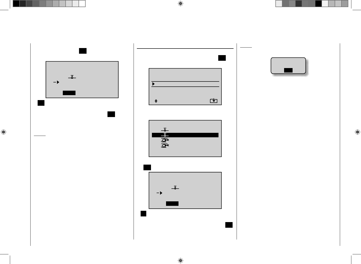
65
Detail program description - Copy / Erase
Once selection of the model memory has been
confi rmed by pressing the SET button, a confi rmation
request will appear.
modell really
ULTIMATE
to be copied?
NO YES
01
03 ¿¿¿frei¿¿¿
ANO response will cancel the process and return the
screen to the originating screen. If the fYES response
is selected and confi rmed by activating the SET button
then the selected source model will be copied into the
selected model memory destination.
Notice:
In addition to model data, binding data is also copied by
this process. This means that a receiver system which
was/is bound to the original model memory can also be
operated by its copy without establishing the bond again.
Export to SD
Select the "Export to SD" sub-menu with the cd arrow
keys of the left or right touch pad and press the SET
button.
=>
=>
=>
=>
=>
=>
=>
Copy flight phase
Erase model
Copy model–>model
Export to SD
Import from SD
Select the model to be exported with the cd arrow
keys of the left or right touch pad.
01
03
04
05 ¿¿frei¿¿
ULTIMATE
02
GRAUBELE
STARLET
BELL47G
export to SD-CARD:
R12
R12
R12
–––
After confi rming the selected model memory by pressing
the SET button, a confi rmation request will appear.
modell
ULTIMATE
export ?
NO YES
01
SD-Karte
ANO response will cancel the process and return the
screen to the originating screen. However, if the fYES
response is selected then confi rmed by pressing the SET
button, the selected model will be copied to the SD card.
Notice:
Should the notice …•
SD-CARD
INSERT
OK
… appear instead of a screen for model selection,
there is no SD card in the transmitter's card slot, see
page 22.
In addition to model data, binding data is also copied •
by this process. This means that a receiver system
which was/is bound to the original model memory
can also be operated in the SAME transmitter by its
copy without establishing the bond again.
An exported winged aircraft model will be stored •
on the memory card in the \\Models\mc-32 folder
with a fi lename format of "aModellname.mdl"
and a helicopter model with a fi lename format
of "hModellname.mdl". On the other hand, if a
"nameless" model is exported, its data will be stored
on the memory card under "ahNoName.mdl" or
"hNoName.mdl", as appropriate.
Some special characters that can be used in model •
names are subject to specifi c restrictions associated
with the FAT or FAT32 fi le system used by the
memory cards and these special characters will be
replaced during the copy process with a tilde (~).
A model fi le already on the memory having the same •
name as the fi le to be copied will be overwritten
without warning.
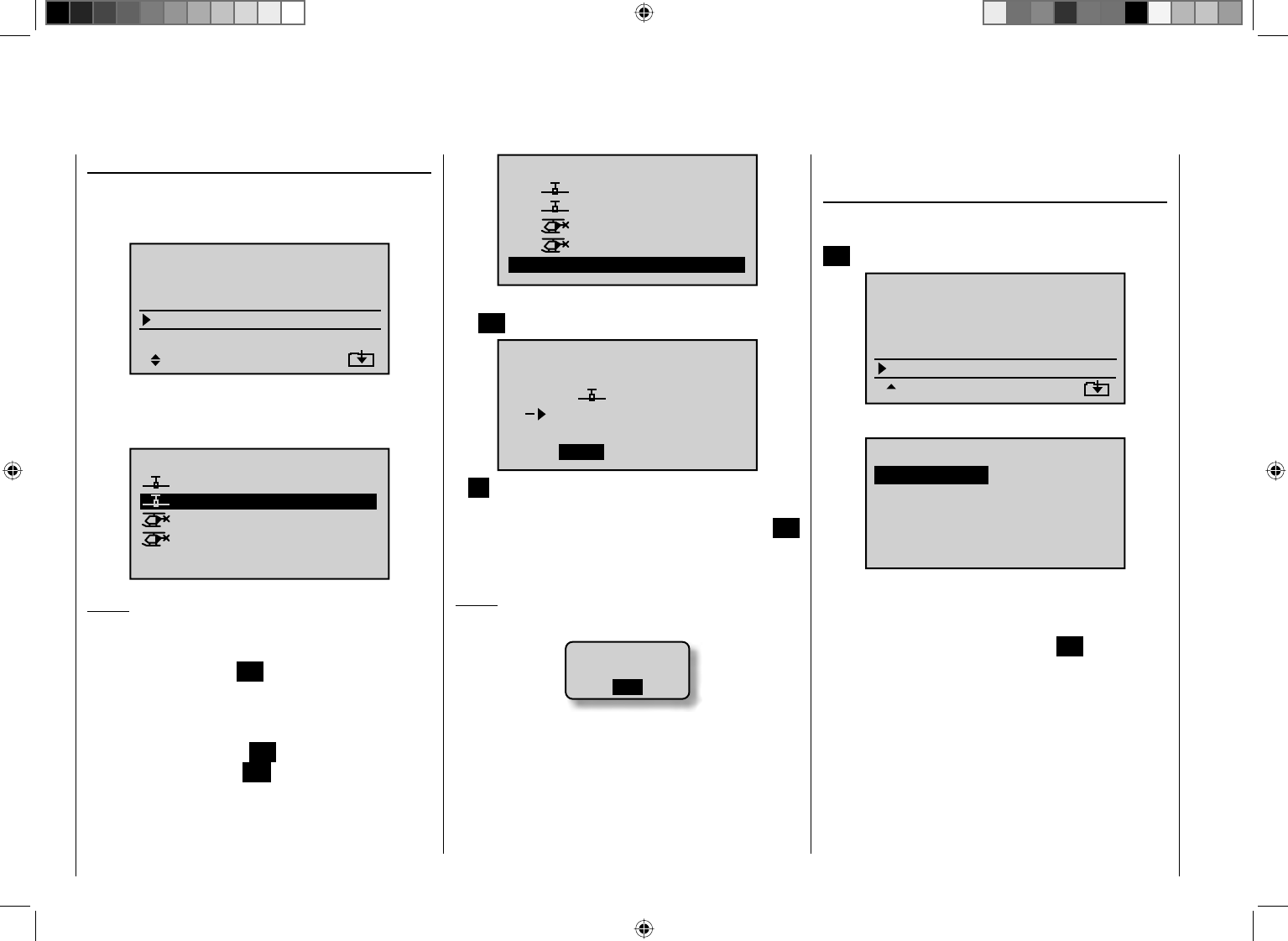
66 Detail program description - Copy / Erase
01
03
04
ULTIMATE
02
GRAUBELE
STARLET
BELL47G
import to model:
05 ¿¿¿free¿¿¿
R12
R12
R12
–––
After confi rming the selected model memory by pressing
the SET button, a confi rmation request will appear.
modell
ULTIMATE
import ?
NO YES
01
03 ¿¿¿free¿¿¿
ANO response will cancel the process and return the
screen to the originating screen. However, if the fYES
response is selected and confi rmed by pressing the SET
button then the selected source model will be imported
into the selected destination model memory.
Notice:
If the message …•
SD-CARD
INSERT
OK
… appears instead of a screen for model selection,
there is no SD card in the transmitter's card slot, see
page 22.
In addition to model data, binding data is also •
imported by this process. This means that a receiver
system which was/is bound to the original model
memory can also be operated in the SAME transmitter
Import from SD
Select the "Import from SD" sub-menu with the
cdarrow keys of the left or right touch pad and press
the SET button.
=>
=>
=>
=>
=>
=>
=>
Copy flight phase
Erase model
Copy model–>model
Export to SD
Import from SD
Select the model to be imported from the SD memory
card with the cd arrow keys of the left or right touch
pad.
05 ¿¿frei¿¿
EXTRA
ALPINA
COBRA
BELL47G
import from SD-CARD:
11/03/10
11/03/11
11/03/11
11/03/12
Notice:
The export date posted at the right end of each model
name line is represented in the format "year/month/day".
After again pressing the SET button in the right touch
pad, the "import to model" window will appear Now
the destination memory location can be selected with
the cd arrow keys of the left or right touch pad and
confi rmed by pressing the SET button or the process
can be canceled with the ESC button. A memory
location which is already occupied can be overwritten.
by its copy without establishing the bond again.
Copy from phase
Select the "Copy from phase" sub-menu with the cd
arrow keys of the left or right touch pad then press the
SET button.
=>
=>
=>
=>
=>
=>
=>
Copy flight phase
Erase model
Copy model–>model
Export to SD
Import from SD
In the "Copy from phase" sub-menu …
7
Copy from phase:
3
5=>
=>
2
4
6
1
… the fl ight phase to be copied (1 … 7 for winged
aircraft models or 1 … 6 for helicopter models) is
selected with the arrow keys of the left or right touch pad
then confi rmed by briefl y pressing the SET button in the
right touch pad. The next window to appear will be the
"Copy to phase" window. In that window the destination
is to be selected and then also confi rmed. As described
above, another confi rmation request will be issued.
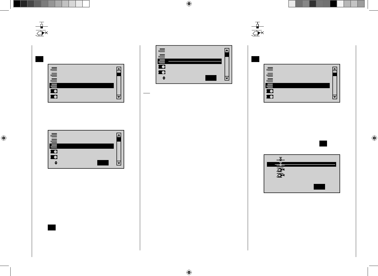
67
Detail program description - Suppress menus and models
Suppress menus
Hide menus in the multifunction
Select the "Suppress menus" menu with the cd arrow
keys of the left or right touch pad then briefl y press the
SET button.
Model select
Base setup model
Model type
Copy / Erase
Suppress menus
Suppress models
In the menu which then appears, menu items which
are no longer needed or those which should not
be changed, can be blocked from appearing in th
multifunction list.
Model select
Base setup model
Model type
Copy / Erase
Suppress models
Suppress: TOG
This reduces the appearance of the multi-function list
considerably, in some cases to only a few menus,
thus substantially improving the clarity of the function
selection list. Functions are not deactivated because
they are hidden. They will simply no longer appear in the
list. This also blocks direct access to these functions.
The function to be hidden or displayed is to be selected
with the arrow keys of the left or right touch pad then
its (hide/display) status switched-over by means of the
center SET button in the right touch pad.
Model select
Base setup model
Model type
Copy / Erase
Suppress models
Suppress: TOG
Tip:
If you wish to forgo access-blockage to the multi-
function list altogether, hide the "Code lock"menu
in the multi-function list by way of this menu as a
precautionary measure.
Suppress models
Hiding model memory locations
Select the "Suppress models" menu with the cd arrow
keys of the left or right touch pad then briefl y press the
SET button.
Model select
Base setup model
Model type
Copy / Erase
Suppress menus
Suppress models
Model memories which are rarely needed or to which
access is to be blocked for other reasons can be hidden
from the model selection list. This also clarifi es the
overview layout for model selection.
A model to be hidden/displayed is selected with the
arrow keys of the left or right touch pad then its status is
switched-over by means of the center SET button in the
right touch pad.
01
03
04
05
ULTIMATE
02
GRAUBELE
STARLET
BELL47G
E12
E12
E12
–––
¿¿¿ free¿¿¿
Suppress: TOG
A model memory which is "stricken through" will no
longer appear in the "Model select" menu.
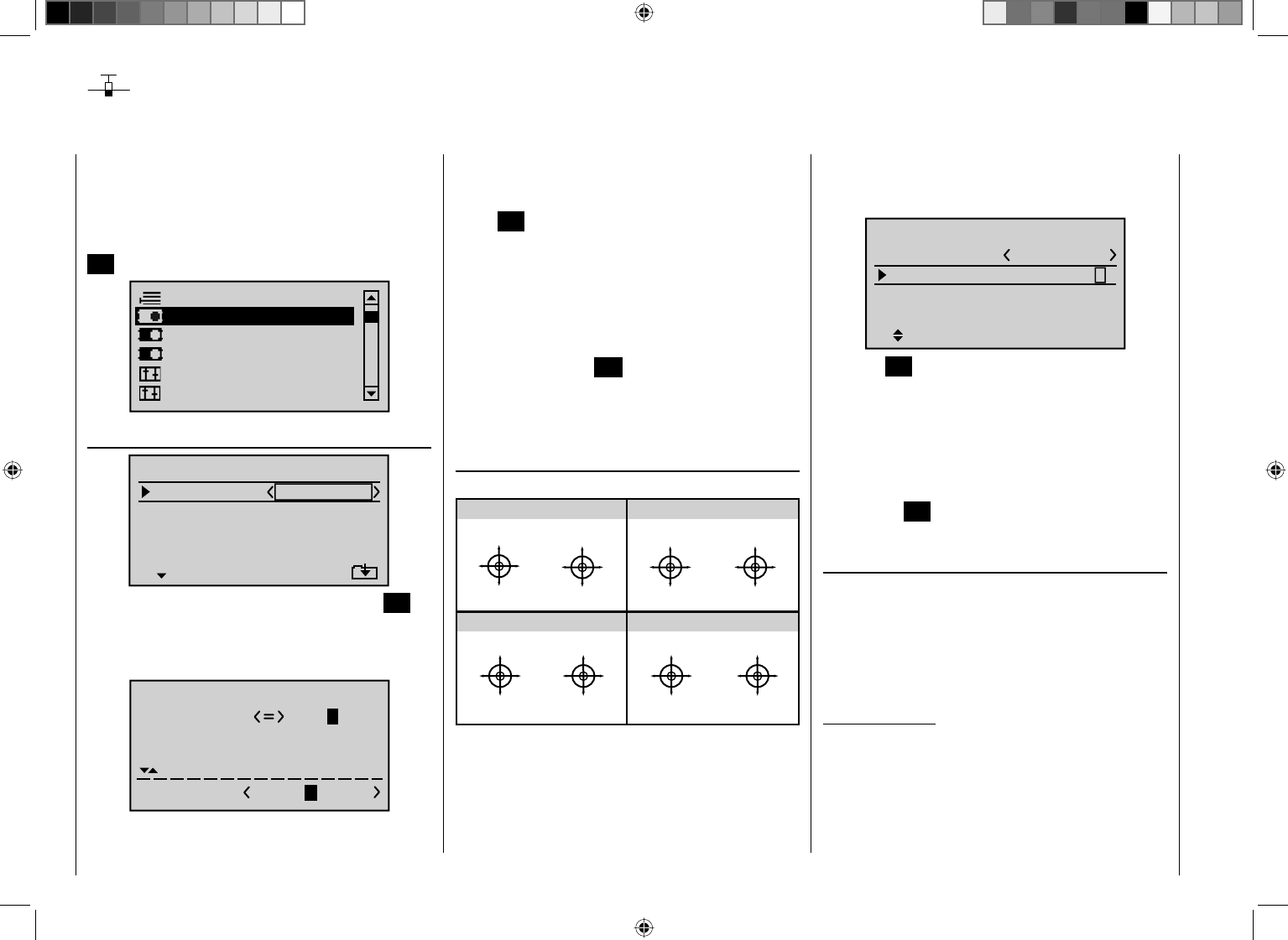
68 Detail program description - Base setup model
Base setup model
Model-specifi c base settings for winged aircraft models
Before programming specifi c parameters, there are
some basic settings to be made which effect the
currently active model memory.
Select the "Base setup model" menu with the arrow
keys of the left or right touch pad then press the center
SET button in the right touch pad.
Model type
Suppress models
Base setup model
Servo adjustment
Control adjust
Stick mode
Model name
Mod.name
Stick mode
RF BIND
1
n/a
BASIC SETTINGS, MODEL
n/a
BD2
BD1
RF transmit OFF
Change to the next screen page by pressing the SET
button briefl y. This will open a screen of characters for
entry of the model's name. A maximum of 9 characters
can be used to specify a model name.
!"#$%&’()+,–./012
3456789:;
Mod Name GRAUB
FGHIJKLMNOPQRSTUVWX
YZ[¥]^_`abcdefghijk
?@ABCDE
Select the desired characters with the arrow keys of the
left touch pad. Move to select the next character position
by pressing the f arrow key of the right touch pad or its
center SET button. Simultaneously pressing the cd or
ef of the right touch pad (CLEAR) will place a space
character at the position.
Positioning to any character position within the entry
fi eld can be done with the ef keys of the right touch
pad.
A return to the previous menu screen is accomplished
by pressing the center ESC button in the left touch pad.
After entering the model name it will appear in the base
screen of the "Model select" menu and in the sub-menu
for the "Copy /Erase" menu item.
S t i c kmode
"MODE 2" (throttle left)
"MODE 3" (throttle right) "MODE 4" (throttle left)
"MODE 1" (throttle left)
Stick forward
Stick back
Rudder left
Rudder right
Motor full throttle
Motor idle
Aileron left
Aileron right
Motor full throttle
Rudder left
Rudder right
Motor idle
Stick forward
Stick back
Aileron left
Aileron right
Stick forward
Stick back
Aileron left
Aileron right
Motor full throttle
Motor idle
Rudder left
Rudder right
Motor full throttle
Motor idle
Aileron left
Aileron right
Stick forward
Stick back
Rudder left
Rudder right
There are four fundamental options for assigning the
four control functions (aileron, elevator, rudder and
throttle/brake fl ap) for a winged aircraft model to the two
joysticks. Just which of these options is chosen depends
on the individual preferences of the individual model
pilot.
Select the "Stick mode" line with the cd arrow keys
of the left or right touch pad. The option fi eld will be
enclosed in a frame.
1
SEL
GRAUBELE
Mod.name
Stick mode
RF BIND n/a
BASIC SETTINGS, MODEL
n/a
RF transmit OFF
Press the SET button. The currently displayed stick
mode will be displayed in inverse video. Now use the
arrow keys of the right touch pad to select from among
options 1 through 4.
Pressing simultaneously on the cd or ef keys of the
right touch pad (CLEAR) will return the option selection
back to stick mode "1".
Pressing the SET button again will deactivate option
selection so that you can change to another line.
Bound receiver
Graupner HoTT receivers must be "instructed" to
communicate exclusively with one particular model
(memory) in a Graupner HoTT transmitter. This
procedure is known as "binding" and must only be done
once for every new receiver/model memory location
combination (and can be repeated anytime).
Important notice:
During the binding procedure be sure the
transmitter's antenna is always far enough away
from the receiver's antenna. To be on the safe side,
keep them at least one meter apart. Otherwise you
run the risk of a faulty connection to the return
channel and malfunctions will result.
69
Detail program description - Base setup model
"RF bind " of transmitter and receiver
Use the cd arrow keys of the left or right touch pad
to move to the screen's "RF bind" line" then select the
desired binding channel. For an example like that shown
in the figure below, choose "BD2" because the binding
channel designated as "BD1" in the screen's bottom line
is already used by default for the receiver which was
delivered with the set.
1
bind
BD1
GRAUBELE
BD2
R12
Mod.name
Stick mode
RF BIND n/a
BASIC SETTINGS, MODEL
Rcv Ch Map n/a
If not already off, now switch the receiver on. The red
LED on the receiver will blink.
Press and hold the SET button on the receiver while
the LED continues to blink red for about 3 seconds then
after about another 3 seconds begins to blink red/green.
You can now release the SET button As long as this
LED blinks red/green, the receiver is in bind mode.
Now, within this 3 second period, start the so-called
"receiver binding" process for the receiver to the
currently active model memory by briefl y pressing the
center SET button of the right touch pad. At this time the
screen's display will begin to indicate the duration of the
"bond".
"Binding" multiple receivers per model
Multiple receivers per model can be bound if desired,
whereby respective mc-32 HoTT programs offer the
potential for managing a maximum of two receivers
directly and for dividing up the 12 control channels (max)
available on these two receivers as desired under menu
control. Refer to additional details further down in this
section. Binding two receivers is begun by fi rst binding
the individual receivers as described below.
In subsequent operation of the model only one of
these receivers will establish a telemetry bond to
the transmitter; the one which was activated in
the "Tel. RCV" line of the "Telemetry" menu. For
example:
TELEMETRY
SETTING & DATA VIEW
SENSOR SELECT
RF STATUS VIEW
VOICE TRIGGER
TEL.RCV BIND. 1
Any telemetry sensors which may be built into the model
should therefore be connected to this receiver because
the transmitter only receives and evaluates data from
the return channel of the receiver activated on this line.
The second, and all other receivers, operate in parallel
but are fully independent in slave mode.
1
BD1
GRAUBELE
BD2
bind
R12
Mod.name
Stick mode
RF BIND n/a
BASIC SETTINGS, MODEL
Rcv Ch Map n/a
Finding ...
If the receiver's LED, again blinking red, changes within
about 10 seconds to continuous illumination in green,
the binding process has been successfully completed.
Your model-memory to receiver combination is now
operationally ready. At this time the screen will now
display "bind" (bound) instead of "n/a" (not attached).
For example:
1
BD1
GRAUBELE
BD2
R08
bind
R12
Mod.name
Stick mode
RF BIND
BASIC SETTINGS, MODEL
Rcv Ch Map
bind
On the other hand, should the LED on the receiver
blink red for longer than about 10 seconds, the binding
process has failed. In this case the screen will continue
to show the status as "n/a". If this should happen, try
changing the position of antennas then repeat the entire
procedure.
Binding other receivers
The binding channel you have chosen is already bound
(as indicated by the "bind" status). with another binding
channel. After initiating the RF bind process, instead
of displaying "BINDING", the message shown below
appears.
70 Detail program description - Base setup model
1
BD1
GRAUBELE
BD2
R08
bind
R12
Mod.name
Stick mode
RF BIND
BASIC SETTINGS, MODEL
Rcv Ch Map
bind
RF
must be
OFF
OK
Drop down two lines in the screen and switch off the
RF module as described on the page in section "RF
module". Afterward, return again to the "RF BIND" line
and restart the process to dissolve bond as described
on the previous page.
Alternatively you can briefl y switch off the transmitter
then, after switching it back on again, respond to the
message window that appears …
RF on/off?
OFF
ON
Please select
… with "OFF" …
RF on/off?
ON
Please select
OFF
… then confi rm the selection by briefl y pressing the
center SET button in the right touch pad. From the base
screen jump again into the "RF BIND" line of the "Basic
settings, model" menu and restart the binding process.
Dissolving a bond
Proceed as described above to initiate the binding
process but WITHOUT first putting a receiver in binding
readiness.
Receiver change map
1
BD1
GRAUBELE
BD2
R08
bind
R12
Mod.name
Stick mode
RF BIND
BASIC SETTINGS, MODEL
Rcv Ch Map
bind
As mentioned in the introduction to the "Binding
receivers" section, the mc-32 HoTT offers both the
opportunity to freely divide up the transmitter's control
channels within a receiver and the opportunity to
distribute the transmitter's 12 control channels across
two receivers.This redistribution is subsequently
referred to as "mapping" or "channel mapping" (channel
correlation). Select the receiver to be "mapped" with
the arrow keys of the left or right touch pad then briefl y
press the center SET button in the right touch pad.
Channel mapping within a receiver
Analogous to the channel correlation function in the
"Telemetry" menu on page 212, described as "Channel
Mapping", it is very simple to use this menu item to
freely distribute the 12 control channels (inputs) to
the outputs (servo connections) of the bound receiver
specifi ed by column BD1.
RECEIVER CH – BIND1
In Ch 1 Out Ch 1
In Ch 2 Out Ch 2
In Ch 3 Out Ch 3
In Ch 4 Out Ch 4
After selection of the desired output with the arrow
keys of the left or right touch pad, the corresponding
input fi eld will be framed. Press briefl y on the center
SET button in the right touch pad. The current setting is
displayed in inverse video. Now select the desired input
channel (= transmitter output, see page 206) with the
arrow keys of the left or right touch pad.
Notice:
The number of lines available in the list (outputs)
corresponds to the maximum number of servos which
can be attached to the given receiver.
BUT CAUTION: If, for example, you have already
specifi ed "2AIL" in the "Aile/fl aps" line of the "Model
type" menu then the transmitter will have allocated
control function 2 (ailerons) for left and right ailerons to
control channels 2 & 5. The corresponding inputs (to the
receiver) in this case would be channels 2 & 5 and these
should be assigned accordingly, refer to the example
below.
Examples:
You would like to control each aileron of a large •
model with two or more servos.
Assign each of the appropriate outputs (servo
connections) to one and the same input (control
channel). In the aforementioned case, to the
giveninput of one of the two default aileron control
channels (2 & 5) appropriate for the left or right wing.
You would like to control the rudder of a large model •
with two or more servos.
Assign each of the appropriate outputs (servo
connections) to one and the same input (control
channel). In this case, the default rudder channel (4),
see fi gure bottom right.
71
Detail program description - Base setup model
Important notice:
By using the mc-32 HoTT transmitter's "Tx. output
swap " option the transmitter's 12 control functions
can be freely swapped in a similar manner or multiple
outputs can be assigned to the same control function.
To avoid confusion, it is strongly recommended that only
one of these two options is used.
Channel assignment on the second receiver
As already mentioned, the "Receiver channel mapping"
option can be used to freely distribute the mc-32
HoTT transmitter's 12 control channels across two
receivers, whereby the numbering sequence of outputs
(servo connections) begun in the "BD1" column for
bound "receiver 1" will be continued. For example, if
"receiver 1" has enough connectors for 12 servos then
the numbering of outputs in the "BD2" column (for the
second bound receiver) will begin with 13.
RECEIVER CH – BIND2
In Ch12 Out Ch13
In Ch12 Out Ch14
In Ch12 Out Ch15
In Ch12 Out Ch16
After selection of the desired output with the arrow
keys of the left and right touch pad, the corresponding
input fi eld will be framed. Press the center SET button
in the right touch pad The current setting is displayed
in inverse video. Now select the desired input channel
with the arrow keys of the right touch pad. For example,
suitable to the above rudder example.
RECEIVER CH – BIND2
Input 4 Out Ch13
Input 4 Out Ch14
Input 4 Out Ch15
Out Ch16
Input 4
Notice:
The number of lines available (outputs) corresponds to
the maximum number of servos which can be connected
to receiver 2 and their numbering is dependent on the
maximum number of servos which can be connected to
receiver 1.
RF transmit
This menu line provides an option for manually
switching the transmitter's RF transmission on and off
to specifi c models while the transmitter is in operation.
For example, to save power while a model is being
programmed. If this line option was set to OFF, it
will be canceled (i.e. set to ON) the next time the
transmitter is switched on.
If necessary, use the cd arrow keys of the left or right
touch pad to reach the "RF transmit" line then activate
the option with by briefl y pressing the center SET button
in the right touch pad
SEL
R12 R08
1
OFF
bind
Stick mode
RF BIND
BASIC SETTINGS, MODEL
Rcv Ch Map
bind
RF transmit
The right arrow keys can now be used to choose
between OFF and ON. Again pressing the center SET
button in the right touch pad will complete the entry.
Range test
The built-in range test reduces transmission power to an
extent that a function test can be carried out even within
a distance of up to about 50 m.
Perform the range test on the Graupner HoTT system
according to the following instructions. If necessary,
have someone assist you in carrying out the range test.
Preferably the receiver already bound to the 1.
transmitter should be installed into the model in its
intended position.
Switch remote control on and wait for the receiver's 2.
green LED to light up. Now servo movements can be
observed.
Place the model on a level surface (pavement, 3.
low-cut grass or bare ground) such that receiver
antennas are at least 15 cm above ground level. It
may be necessary to put something under the model
to raise it up enough for this.
Hold the transmitter at hip level and at some distance 4.
from one's body. Do not point the antenna directly at
the model but rather turn and/or kink the antenna's
end so that it is oriented vertically during the test.
If necessary, use the 5. cd arrow keys of the left or
right touch pad to reach the "RF Range Test" line in
the menu then start range test mode by pressing the
center SET button in the right touch pad.
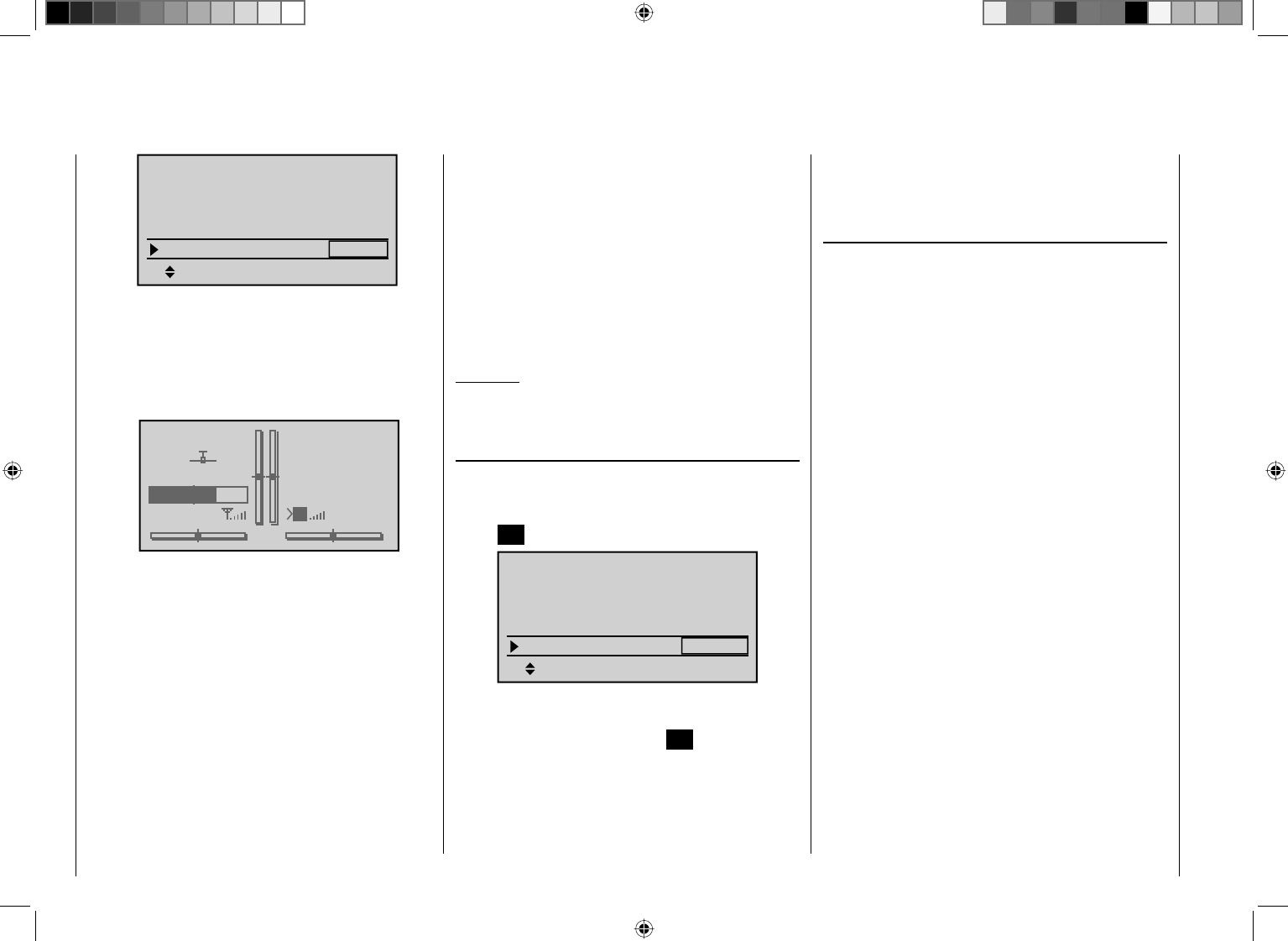
72 Detail program description - Base setup model
SEL
RF Range Test 99sec
R12 R08
OFF
bind
RF BIND
BASIC SETTINGS, MODEL
Rcv Ch Map
bind
RF transmit
When the range test is activated, the transmitter's
output power will be signifi cantly reduced and the
blue LED on the antenna's socket will begin to
blink. At the same time, the timer display in the
transmitter's screen will start counting down and
every 5 seconds a two-frequency tone will sound.
GRAUBELE
#01
2:22h
Stop
Flt
«normal »
K78
0:00
0:00
5.5V
5.2V
M
HoTT
TEST 76s
Five seconds prior to the end of the range test a
three-frequency tone will sound once every second.
After expiration of the range test's 99th second the
transmitter will again be switched to full output power
and the blue LED will again illuminate constantly.
Move away from the model while manipulating 6.
the joysticks during this timespan. If you notice an
interruption anytime while still within a distance of
about 50 m, try to reproduce this malfunction.
If there is a motor in the model, it may be necessary 7.
to switch it on to further check noise immunity.
Continue moving away from the model until perfect 8.
control is no longer possible.
Wait at this distance for the remainder of the test 9.
period with the still-operationally-ready model to
expire. After the range test is ended it should again
respond correctly to all RC controls. If this is not 100
% the case, do not use the system. Contact your
area's Graupner GmbH & Co. KG service partner.
Perform the range test before each fl ight and, in 10.
doing so, simulate all servo movements which also
take place during fl ight. The range must always be
at 50 m on the ground in order to assure safe model
operation.
Attention:
Never start the range test on the transmitter during
normal operation of the model.
DSC output
If necessary, use the cd arrow keys of the left or right
touch pad to reach the "DSC output" line of the menu
then activate this menu item by briefl y pressing the
center SET button in the right touch pad.
SEL
99sec
DSC output PPM10
RF Range Test
R12 R08
OFF
BASIC SETTINGS, MODEL
Rcv Ch Map
RF transmit
Now you can use the right arrow keys to choose
between three types of modulation "PPM10", "PPM18"
and "PPM24". Pressing the center SET button in the
right touch pad again will complete the entry.
This choice primarily infl uences the maximum number
of control channels which can be attached to the DSC
(direct servo control) socket, and thus also available to
a fl ight simulator or teacher/pupil system. This maximum
is control channels 1 ... 5 if "PPM10" is selected, control
channels 1 ... 9 for "PPM18" and control channels 1 ...
12 for "PPM24".
Cut-off
Depending on the "idle forward or back" choice made
in the "Motor at C1" line of the "Model type" menu, this
motor "cut off" option can be coupled to a switch for
throttling down a speed controller or to move a servo on
the carburetor of a motor to the OFF (or idle) position.
The motor OFF position (or idle setting) will then
be preset by the left column directly over the "SEL"
fi eld. The appropriate value for this entry fi eld is to be
established through trial and error
A speed controller or throttle servo will only take on
this preset position when a certain servo position or
threshold is underrun and a switch is activated. This is
done by setting the desired servo position (threshold
value) into the middle column, directly over the "STO"
fi eld then selecting the appropriate ON/OFF switch
function in the right column.
If the percentage value specifi ed for the middle •
column is greater than the current servo position, i. e.
the current servo position lies below the threshold,
the switchover will occur as soon as the switch is put
into its ON position.
If the percentage value specifi ed for the middle •
column is less than the current servo position, i. e.
the current servo position is above the threshold, the
speed controller will initially reduce motor speed or
close the carburetor's throttle servo only to the extent
dictated by the value in the left column as soon as
the servo's position once underrunsthe threshold
(max. +150 %) after the switch is changed over to its
73
Detail program description - Base setup model
ON position.
The speed controller or throttle servo will remain in
this cut-off position only until the selected switch is
again changed over followed by a one-time throttle
servo or speed controller movement beyond the preset
threshold with the throttle/brake joystick control.
The factory setting for the left column is -100 % for
the throttle servo "cut-off" position and a threshold of
+150 % servo position setting in the middle column.
SEL
99sec
PPM10
–––
cut off +150%–100%
STO
DSC Output
RF Range Test
OFF
BASIC SETTINGS, MODEL
RF transmit
Programming
To change the preset "cut-off" position of the throttle
servo, press the center SET button in the right touch
pad. The current setting will be displayed in inverse
video. Now use the arrow keys of the left or right touch
pad to set a value at which the motor is reliably "off". If a
combustion motor is involved, be sure the throttle servo
does not perform mechanical runout, e. g. -125 %.
SEL
OFF
99sec
PPM10
–––
+150%
STO
–125%
cut off
DSC output
RF Range Test
BASIC SETTINGS, MODEL
RF transmit
The – upper – preset value in the middle column
ensures the motor can be stopped, throughout the
maximum possible positioning range of the servo or
speed controller, alone by the switch to be assigned in
the right column.
However, if you wish to set a lower threshold, by which
an underrun will cause the throttle servo or speed
controller with closed switch to switch into the cut-off
position, reduce the preset servo travel from +150 %
by placing the throttle servo or speed controller into
the desired position with the throttle/brake joystick then
press the center SET button in the right touch pad.
SEL
99sec
PPM10
–––
STO
–125% +100%
cut off
DSC output
RF Range Test
BASIC SETTINGS, MODEL
RF transmit OFF
Finally, use the column at the right to specify a
switch with which you can cut off the motor directly
(emergency) or which will be activated by the threshold.
SEL
99sec
PPM10
8
STO
–125% +100%
cut off
DSC output
RF Range Test
BASIC SETTINGS, MODEL
RF transmit OFF
Notices:
Be sure the throttle servo does not run out •
mechanically when the cut-off function is activated.
A threshold over +100 % is reached by temporarily •
increasing the travel for servo 1 in the "Servo
adjustment" menu to over 100 % then, after storing
the threshold, change servo travel back to the
original value.
74 Detail program description - Base setup model | Helicopter
Before programming specifi c parameters, there are
some basic settings to be made which effect the
currently active model memory. Select the "Base setup
model " menu with the arrow keys of the left or right
touch pad then press the center SET button in the right
touch pad.
Helicopter type
Suppress models
Base setup model
Servo adjustment
Control adjust
Stick mode.
Model name
Mod.name
Stick mode
RF BIND
1
n/a
BASIC SETTINGS, MODEL
n/a
BD2
BD1
RF transmit OFF
Change to the next screen page by briefl y pressing
the SET button in the right touch pad. This will open
a screen of characters for entry of the model's name.
A maximum of 9 characters can be used to specify a
model name.
!"#$%&’()+,–./012
3456789:;
Mod Name STARL
FGHIJKLMNOPQRSTUVWX
YZ[¥]^_`abcdefghijk
?@ABCDE
Select the desired characters with the arrow keys of the
left touch pad. Move to select the next character position
by pressing the f arrow key of the right touch pad or its
center SET button Simultaneously pressing on the cd
or ef keys of the right touch pad (CLEAR) will place a
space character at the position.
Positioning to any character position within the entry fi eld
can be done with the ef keys of the right touch pad.
A return to the previous menu screen is accomplished
by pressing the center ESC button in the left touch pad.
A model name entered in this manner will appear in the
base screen of the "Model select" menu and in the sub-
menus of the "Copy / Erase" menu item.
Stick mode
"MODE 2" (throttle left)
"MODE 3" (throttle right) "MODE 4" (throttle left)
"MODE 1" (throttle left)
TS-Nick
Tail
Nick
Tail
Motor/Pitch
Roll
Roll
Motor/Pitch
Tail
Tail
Motor/Pitch Motor/Pitch
Nick
Nick
Roll
Roll
Nick
Nick
Roll
Roll
Motor/Pitch
Motor/Pitch
Tail
Tail
Motor/Pitch
Motor/Pitch
Roll
Roll
Nick
Nick
Tail
Tail
Basically there are four different ways to assign the
four helicopter control functions, roll, nick, tail rotor and
throttle/pitch to the two joysticks. Just which of these
is used depends on the preferences of the individual
model pilot.
Use the cd arrow keys of the left or right touch pad
to select the "Stick mode" line. The option fi eld will be
framed.
1
SEL
STARLET
Mod.name
Stick mode
RF BIND n/a
BASIC SETTINGS, MODEL
n/a
RF transmit OFF
Press the SET button. The currently displayed stick
mode will be displayed in inverse video. Now use the
arrow keys of the right touch pad to select from among
options 1 through 4.
Pressing simultaneously on the cd or ef keys of the
right touch pad (CLEAR) will return the option selection
back to stick mode "1".
Pressing the SET button again will deactivate option
selection so that you can change to another line.
Bound receiver
Graupner-HoTT receivers must be "instructed " to
communicate exclusively with one particular model
(memory) in a Graupner-HoTT transmitter. This
procedure is known as "binding" and must only be done
once for every new receiver/model memory location
combination (and can be repeated anytime).
Important notice:
During the binding procedure be sure the
transmitter's antenna is always far enough away
from the receiver's antenna. To be on the safe side,
keep them at least one meter apart. Otherwise you
run the risk of a faulty connection to the return
channel and malfunctions will result.
"Binding" multiple receivers per model
Multiple receivers per model can be bound if desired,
Base setup model
Model-specifi c base settings for helicopter models
75
Detail program description - Base setup model | Helicopter
whereby respective mc-32 HoTT programs offer the
potential for managing a maximum of two receivers
directly and for dividing up the 12 control channels (max)
available on these two receivers as desired under menu
control. Refer to additional details further down in this
section. Binding two receivers is begun by fi rst binding
the individual receivers as described below.
In subsequent operation of the model only one of
these receivers will establish a telemetry bond to
the transmitter; the one which was activated in
the "Tel. RCV" line of the "Telemetry" menu. For
example:
TELEMETRY
SETTING & DATA VIEW
SENSOR SELECT
RF STATUS VIEW
VOICE TRIGGER
TEL.RCV BIND. 1
Any telemetry sensors which may be built into the model
should therefore be connected to this receiver because
the transmitter only receives and evaluates data from
the return channel of the receiver activated on this line.
The second, and all other receivers, operate in parallel
but are fully independent in slave mode.
"Binding" the transmitter and receiver
Use arrow keys cdof the left or right touch pad to
move to the screen's "RF bind" line then select the
desired binding channel. For an example like that shown
in the figure below, choose "BD2" because the binding
channel designated as "BD1" in the screen's bottom line
is already used by default for the receiver which was
delivered with the set.
1
bind
BD1
STARLET
BD2
R12 n/a
Mod.name
Stick mode
RF BIND n/a
BASIC SETTINGS, MODEL
Rcv Ch Map
If not already off, now switch the receiver on. The red
LED on the receiver will blink.
Press and hold the SET button on the receiver while
the LED continues to blink red for about 3 seconds then
after about another 3 seconds begins to blink red/green.
You can now release the SET button As long as this
LED blinks red/green, the receiver is in bind mode.
Now, within this 3 second period, start the so-called
"receiver binding" process for the receiver to the
currently active model memory by briefl y pressing the
center SET button of the right touch pad. At this time the
screen's display will begin to indicate the duration of the
"bond".
1
bind
BD1
STARLET
BD2
R12 n/a
Mod.name
Stick mode
RF BIND n/a
BASIC SETTINGS, MODEL
Rcv Ch Map
Finding ...
If the receiver's LED, again blinking red, changes within
about 10 seconds to continuous illumination in green,
the binding process has been successfully completed.
Your model-memory to receiver combination is now
operationally ready. At this time the screen will now
display "bind" (bound) instead of "n/a" (not attached).
For example:
1
bind
BD1
STARLET
BD2
R08
bind
R12
Mod.name
Stick mode
RF BIND
BASIC SETTINGS, MODEL
Rcv Ch Map
On the other hand, should the LED on the receiver
blink red for longer than about 10 seconds, the binding
process has failed. In this case the screen will continue
to show the status as "n/a". If this should happen, try
changing the position of antennas then repeat the entire
procedure.
Binding other receivers
The binding channel you have chosen is already bound
(as indicated by the "bind" status). with another binding
channel. If, after initiating the RF bind process, the
message shown below appears in the screen instead of
displaying "BINDING"
76 Detail program description - Base setup model | Helicopter
1
bind
BD1
STARLET
BD2
R08
bind
R12
Mod.name
Stick mode
RF BIND
BASIC SETTINGS, MODEL
Rcv Ch Map
RF
must be
OFF
OK
Drop down two lines in the screen and switch off the
RF module as described on the page in section "RF
module". Afterward, return again to the "RF BIND" line
and restart the process to dissolve bond as described
on the previous page.
Alternatively you can briefl y switch off the transmitter
then, after switching it back on again, respond to the
message window that appears …
RF on/off?
OFF
ON
Please select
… with "OFF" …
RF on/off?
ON
Please select
OFF
… then confi rm the selection by briefl y pressing the
center SET button in the right touch pad. From the base
screen jump again into the "RF BIND" line of the "Basic
settings, model" menu and restart the binding process.
Dissolving a bond
Proceed as described above to initiate the binding
process but WITHOUT first putting a receiver in binding
readiness.
Receiver change map
1
BD1
STARLET
BD2
bind
R08
bind
R12
Mod.name
Stick mode
RF BIND
BASIC SETTINGS, MODEL
Rcv Ch Map
As mentioned in the introduction to the "Binding
receivers" section, the mc-32 HoTT offers both the
opportunity to freely divide up the transmitter's control
channels within a receiver as well as the opportunity to
distribute the transmitter's 12 control channels across
two receivers. This redistribution is subsequently
referred to as "mapping" or "channel mapping" (channel
correlation). Select the receiver to be "mapped" with
the arrow keys of the left or right touch pad then briefl y
press the center SET button in the right touch pad.
Channel mapping within a receiver
Analogous to the channel correlation function in the "
Telemetry " menu on page 212, described as "Channel
Mapping", it is very simple to use this menu item to
freely distribute the 12 control channels (inputs) to
the outputs (servo connections) of the bound receiver
specifi ed by column BD1.
RECEIVER CH – BIND1
In Ch 1 Out Ch 1
In Ch 2 Out Ch 2
In Ch 3 Out Ch 3
In Ch 4 Out Ch 4
After selection of the desired output with the arrow keys
of the left and right touch pad, the corresponding input
fi eld will be framed. Press briefl y on the center SET
button in the right touch pad. The current setting will be
displayed in inverse video. Now select the desired input
channel (= transmitter output, see page 206) with the
arrow keys of the left or right touch pad.
Notice:
The number of lines available in the list (outputs)
corresponds to the maximum number of servos which
can be attached to the given receiver.
BUT CAUTION: If you wish to operate two servos with
one control function, for example such as transmitter
control function 2 (roll) which is divided up into
control channels 1 & 2 for left and right roll servos by
"3Sv(2Roll)" in the " in the "Heli Type" menu; then
"map" transmitter outputs 1 & 2 (= inputs to the receiver)
accordingly.
Important notice:
By using the mc-32 HoTT transmitter's "Tx. output
swap" option, the transmitter's 12 control functions
can be freely swapped in a similar manner or multiple
outputs can be assigned to the same control function.
To avoid confusion, it is strongly recommended that only
one of these two options is used.
Channel assignment on the second receiver
As already mentioned, the "Receiver channel mapping"
option can be used to freely distribute the mc-32
HoTT transmitter's 12 control channels across two
receivers, whereby the numbering sequence of outputs
(servo connections) begun in the "BD1" column for
bound "receiver 1" will be continued. For example, if
"receiver 1" has enough connectors for 12 servos then
the numbering of outputs in the "BD2" column (for the
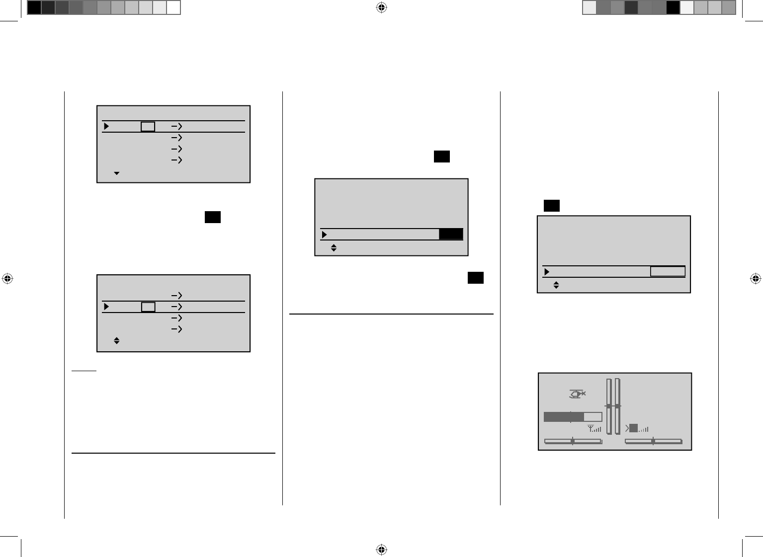
77
Detail program description - Base setup model | Helicopter
second bound receiver) will begin with 13.
RECEIVER CH – BIND2
In Ch12 Out Ch13
In Ch12 Out Ch14
In Ch12 Out Ch15
In Ch12 Out Ch16
After selection of the desired output with the arrow keys
of the left and right touch pad, the corresponding input
fi eld will be framed. Press the center SET button in the
right touch pad The current setting will be displayed
in inverse video. Now select the desired input channel
with the arrow keys of the right touch pad. For example,
appropriate for the above example with roll servos:
In Ch 2 Out Ch14
In Ch12 Out Ch15
In Ch12 Out Ch16
RECEIVER CH – BIND1
In Ch 1 Out Ch13
Notice:
The number of lines available (outputs) corresponds to
the maximum number of servos which can be connected
to receiver 2 and their numbering is dependent on the
maximum number of servos which can be connected to
receiver 1.
RF transmit
This menu line provides an option for manually
switching the transmitter's RF transmission on and off
to specifi c models while the transmitter is in operation.
For example, to save power while a model is being
programmed. If this line option was set to OFF, it
will be canceled (i.e. set to ON) the next time the
transmitter is switched on.
If necessary, use the cdarrow keys of the left or right
touch pad to reach the "RF transmit " line then activate
the option by briefl y pressing the center SET button in
the right touch pad.
SEL
R12 R08
1
OFF
bind
Stick mode
RF BIND
BASIC SETTINGS, MODEL
Rcv Ch Map
bind
RF transmit
The right arrow keys can now be used to choose
between OFF and ON. Again pressing the center SET
button in the right touch pad will complete the entry.
Range test
The built-in range test reduces transmission power to an
extent that a function test can be carried out even within
a distance of up to about 50 m.
Perform the range test on the Graupner HoTT system
according to the following instructions. If necessary,
have someone assist you in carrying out the range test.
Preferably the receiver already bound to the 1.
transmitter should be installed into the model in its
intended position.
Switch remote control on and wait for the receiver's 2.
green LED to light up. Now servo movements can be
observed.
Place the model on a level surface (pavement, 3.
low-cut grass or bare ground) such that receiver
antennas are at least 15 cm above ground level. It
may be necessary to put something under the model
to raise it up enough for this.
Hold the transmitter at hip level and at some distance 4.
from one's body. Do not point the antenna directly at
the model but rather turn and/or kink the antenna's
end so that it is oriented vertically during the test.
If necessary, use the 5. cdarrow keys of the left or
right touch pad to reach the "RF Range Test" line in
the menu then start range test mode by pressing the
center SET button in the right touch pad.
SEL
RF Range Test 99sec
R12 R08
OFF
bind
RF BIND
BASIC SETTINGS, MODEL
Rcv Ch Map
bind
RF transmit
When the range test is activated, the transmitter's
output power will be signifi cantly reduced and the
blue LED on the antenna's socket will begin to
blink. At the same time, the timer display in the
transmitter's screen will start counting down and
every 5 seconds a two-frequency tone will sound.
STARLET
#02
2:22h
Stop
Flt
«normal »
K78
0:00
0:00
5.5V
5.2V
M
HoTT
TEST 76s
Five seconds prior to the end of the range test a
three-frequency tone will sound once every second.
After expiration of the range test's 99th second the
transmitter will again be switched to full output power
78 Detail program description - Base setup model | Helicopter
SEL
99sec
DSC output PPM10
RF Range Test
R12 R08
OFF
BASIC SETTINGS, MODEL
Rcv Ch Map
RF transmit
Now you can use the right arrow keys to choose
between three types of modulation "PPM10", "PPM18"
and "PPM24". Pressing the center SET button in the
right touch pad again will complete the entry.
This choice primarily infl uences the maximum number
of control channels which can be attached to the DSC
(direct servo control) socket, and thus also available to
a fl ight simulator or teacher/pupil system. This maximum
is control channels 1 ... 5 if "PPM10" is selected, control
channels 1 ... 9 for "PPM18" and control channels 1 ...
12 for "PPM24".
Autorotation
Autorotation is that state of descending fl ight in which
the pitch of main rotor blades are set such that the
rotor's speed matches the natural forces of air fl owing
through, like a windmill. This built-up energy can be
used for "recovery" lift to brake a descent by appropriate
blade pitch adjustment.
Autorotation is a means by which real and model
helicopters are able to land safely in emergency
situations, e. g. in the event of a motor failure. However,
the prerequisite for this is a well-trained pilot familiar
with the helicopter's characteristics. Quick reaction and
good perceptiveness are necessary because the rotor's
inertia can only be used once to generate recovery lift.
When this technique is evaluated during competitions,
the motor must be switched off for autorotation. For
training purposes it is better to keep the motor running
at idle during autorotation.
The Autorotation switch causes a switchover to the
autorotation fl ight phase in which control of "throttle" and
"pitch" are separate and all mixers which have an effect
on the throttle servo are switched off. Corresponding
parameter settings are made in the "Helicopter mixer"
menu (see page 178); refer also to the "Principle of the
Auto. C1 Pos." topic which follows.
The "Autorotation" name is permanently assigned to
phase 1 and it is included in the base screen of all
fl ight phase dependent menus. This name can NOT
be changed. It is only possible to assign a switch to
this option, as described on page 52. If a switch is
assigned, it will have absolute priority over all other
fl ight-phase switches.
Input
Output
Point ?
0%
0%
–100%
C1
Normal
Thr
Curve off
More about fl ight-phase programming can be found
in the text beginning on page 164 in the "Helicopter
mixer" section.
Auto.C1 Pos. (Autorotation C1 position)
The autorotation fl ight-phase can alternatively be
activated by a threshold point for the C1 throttle/pitch
joystick. To set such a threshold, use the cd arrow
keys of the left or right key pad to reach the "Auto.C1
Pos." line.
and the blue LED will again illuminate constantly.
Move away from the model while manipulating 6.
the joysticks during this timespan. If you notice an
interruption anytime while still within a distance of
about 50 m, try to reproduce this malfunction.
If there is a motor in the model, it may be necessary 7.
to switch it on to further check noise immunity.
Continue moving away from the model until perfect 8.
control is no longer possible.
Wait at this distance for the remainder of the test 9.
period with the still-operationally-ready model to
expire. After the range test is ended it should again
respond correctly to all RC controls. If this is not
100 % the case, do not use the system. Contact your
area's Graupner GmbH Co. KG service partner.
Perform the range test before each fl ight and, in 10.
doing so, simulate all servo movements which also
take place during fl ight. The range must always be
at 50 m on the ground in order to assure safe model
operation.
Attention:
Never start the range test on the transmitter during
normal operation of the model.
DSC output
If necessary, use the cd arrow keys of the left or right
touch pad to reach the "DSC output" line then activate
this menu item by pressing the center SET button of the
right touch pad.
79
Detail program description - Base setup model | Helicopter
As soon as this line has been selected, the value fi eld
in its column directly above STO on the screen's bottom
line will be framed.
99sec
PPM10
–––
–––
Auto.C1 Pos. 0%
STO
DSC Output
Autorotation
BASIC SETTINGS, MODEL
RF Range Test
Move the C1 joystick into the desired threshold
switchover position then press the center SET button in
the right touch pad. The current value will be displayed,
e. g.:
99sec
PPM10
–––
–––
-55%
STO
Auto.C1 Pos.
DSC Output
Autorotation
BASIC SETTINGS, MODEL
RF Range Test
After this has been done, use the arrow keys to move
into the column above the switch symbol then assign a
switch to this fi eld, as described on page 52 in section
"Switches, controls and control switches". Preferably the
selection will be one of the two self-resetting switches,
SW 1 or 9.
99sec
PPM10
–––
-55%
STO
9
Auto.C1 Pos.
DSC Output
Autorotation
BASIC SETTINGS, MODEL
RF Range Test
Once this activation switch is closed, the fi rst occurrence
of a threshold underrun will cause the program to switch
over to "Autorotation" and then remain independent of
C1 position in this fl ight phase until the activating switch,
in this example SW 9, is again "OFF".
"Auto. C1 Pos." has precedence over all other fl ight-
phase switches.
Corresponding parameter settings for …
pitch servos•
throttle servo•
tail rotor servo•
swashplate rotation, if available•
gyro setting•
… are made in the "Helicopter mixer" menu, see
page 64.
Cut-off
Within the framework of autorotation settings for the
mc-32 HoTT transmitter's helicopter program, there
are parameters for an emergency "cut off" of the throttle
servo or motor actuator, refer to the programming
proposal on page 286. However, this option is not
available if an idle position is specifi ed in the "Thr
setting AR" line of the "Helicopter mixer" menu
instead of an (emergency) OFF position; for example,
to avoid restarting the motor after every landing during
autorotation practice. In this case it is better to use this
option as a "cut off" rather than as an emergency OFF
solution.
Depending on the "forw./back" choice made for the
"Pitch min" line of the "Heli Type" menu, this motor "cut
off" option can be coupled to a switch for throttling down
a carburetor servo to the cut-off (or idle) position.
This cut-off (or idle) position is specifi ed by the left
column over the "SEL" fi eld and its value is to be
established through trial and error.
A speed controller or throttle servo will only take on
this preset position when a certain servo position or
threshold is underrun and a switch is activated. This is
done by setting the desired servo position (threshold
value) into the middle column, directly over the "STO"
fi eld then selecting the appropriate ON/OFF switch
function in the right column.
If the percentage value specifi ed for the middle •
column is greater than the current servo position, i. e.
the current servo position lies below the threshold,
the switchover will occur as soon as the switch is put
into its ON position.
If the percentage value specifi ed for the middle •
column is less than the current servo position, i. e.
the current servo position is above the threshold, the
speed controller will initially reduce motor speed or
close the carburetor's throttle servo only to the extent
dictated by the value in the left column as soon as
the servo's position once underruns the threshold
(max. +150 %) after the switch is changed over to its
ON position.
The speed controller or throttle servo will remain in
this cut-off position only until the selected switch is
again changed over followed by a one-time throttle
servo or speed controller movement beyond the
preset threshold with the throttle/brake joystick
control.
The factory setting for the left column is -100 % for
the throttle servo "cut-off" position and a threshold of
+150 % servo position setting in the middle column.
80 Detail program description - Base setup model | Helicopter
PPM10
–––
-55% 9
SEL
–––
cut off +150%–100%
STO
Auto.C1 Pos.
DSC Output
Autorotation
BASIC SETTINGS, MODEL
Programming
To change the preset "cut-off" position of the throttle
servo, press the center SET button in the right touch
pad. The current setting will be displayed in inverse
video. Now use the arrow keys of the left or right touch
pad to set a value at which the motor is reliably "off"
without a startup of the throttle servo. For example
-125 %:
PPM10
–––
-55% 9
SEL
–––
+150%
STO
–125%cut off
Auto.C1 Pos.
DSC Output
Autorotation
BASIC SETTINGS, MODEL
The – upper – preset value in the middle column
ensures the motor can be stopped, throughout the
maximum possible positioning range of the servo or
speed controller, alone by the switch to be assigned in
the right column.
However, if you wish to set a lower threshold, by
which an underrun will cause the throttle servo or
speed controller with closed switch to switch into the
cut-off position, reduce the preset servo travel and - if
applicable, the throttle limiter - by placing the throttle/
pitch joystick into the desired position then press the
center SET button in the right touch pad.
PPM10
–––
-55% 9
SEL
–––
+100%
STO
–125%
cut off
Auto.C1 Pos.
DSC Output
Autorotation
BASIC SETTINGS, MODEL
Finally, use the column at the right to specify a
switch with which you can cut off the motor directly
(emergency) or which will be activated by the threshold.
PPM10
–––
-55% 9
SEL
+100%
STO
–125% 1
cut off
Auto.C1 Pos.
DSC Output
Autorotation
BASIC SETTINGS, MODEL
Notices:
Be sure the throttle servo does not run out •
mechanically when the cut-off function is activated.
A threshold over +100 % is reached by temporarily •
increasing the travel for servo 1 in the "Servo
adjustment" menu to over 100 % then, after storing
the threshold, change servo travel back to the
original value.

81
Your notes
82 Detail program description - Model type
This "Model type" menu is used to establish the
type of model to be programmed. This also activates
all characteristic mixers, coupling functions, etc.
in preparation for subsequent programming of the
specifi ed model type.
Suppress model
Base setup model
Servo adjustment
Control adjust
Model type
Stick mode.
Press briefl y on the center SET button in the right touch
pad.
Motor at C1
After selecting the "Motor at C1" line with the cd arrow
keys of the left and right touch pad, the corresponding
entry fi eld will be framed.
Tail type
Motor at C1
Normal
None
Aile/flaps 1AIL
M O D E L T Y P E
Brake Off In 1+100%
SEL
Press briefl y on the center SET button in the right touch
pad. The current setting will be displayed in inverse
video. Now use the arrow keys of the right touch pad to
select from among the following four options:
"none" For operation of a model without a
propulsion.
The warning "Throttle too high", see
page 36, is deaktivated and the "Brake
settings" sub-menu of the "Wing
mixers" menu (beginning page 146) is
available without any restrictions.
"back": The idle position for the throttle/brake
fl aps control stick (C1) is to the rear, i. e.
toward the pilot.
The warnings "Throttle too high", see
page 36, as well as the "cut off" option
in the "Basic settings, model" menu,
see page 72, are activated and the
"Brake settings" sub-menu of the "Wing
mixers", beginning page 146, will be
available if the entry in the "Motor"
column of the "Phase settings" menu,
page 128 for the currently active fl ight
phase contains "none".
"forw.": The idle position for the throttle/brake
fl aps control stick (C1) is at the front, i. e.
away from the pilot.
The warnings "Throttle too high", see
page 36, as well as the "cut off" option
in the "Basic settings, model", see
page 72, are activated and the "Brake
settings" sub-menu of the "Wing
mixers", beginning page 146, will be
available if the entry in the "Motor"
column of the "Phase settings" menu,
page 128 for the currently active fl ight
phase is "none".
Notice:
Be sure to pay attention during the programming •
procedures that motors do not start up
unintentionally. Disconnect the fuel supply or
battery terminals to motors before programming.
C1 trimming will operate according to your choice •
between "normal" or only "back" or "fwd.", that is,
either over the control's entire travel path or only in
the respective idle direction.
Pay attention to the "• cut off trim" function described
on page 54.
Tail type
After selecting the "Tail type" line with the cd arrow
keys of the left or right touch pad, the corresponding
entry fi eld will be framed.
+100%
SEL
Tail type
Motor at C1
Normal
None
Aile/flaps 1AIL
M O D E L T Y P E
Brake Off In 1
Press briefl y on the center SET button in the right touch
pad. The current setting will be displayed in inverse
video. Now select the type applicable to your model with
the arrow keys of the right touch pad.
"normal": Elevators and rudder are each operated
by a single servo.
"V-tail": Elevator and rudder control is affected
by way of two separate, articulated,
V-shaped rudders. The coupling function
for rudder and elevator control will be
automatically taken over by the program.
The relationship of rudder-to-elevator
proportion is set in the "Dual Rate /
Expo" menu, page 108 and servo travel
in the "Servo adjust" menu, page 90.
If differentiated rudder throw is also
desired then the V-tail should be
Model type
Establishing winged aircraft model type
83
Detail program description - Model type
controlled instead by way of the "Dual
mixer" menu, page 194. In this case
however, the tail type entry specifi ed here
must be "normal".
"Delta/fl ": Aileron and elevator control is operated
by one or two servos per wing half.
However, elevator trimming is also
affected by selecting the "QR 2WK"
option – see below – but only on servos 2
& 3.
"2HRSv3+8": This option is intended for models
with two elevator servos. The servo
connected to output 8 will operate in
parallel with servo 3 to actuate elevators.
Elevator trimming affects both servos.
Notice about the "2HRSv3+8" option:
One control, which assigns input 8 by
way of the "Control adjust" menu, is
then disconnected from servo "8" by
software for reasons of safety i. e. it is
made ineffective.
Aileron/Flaps
After selecting the "Aile/fl aps" line with the cd arrow
keys of the left or right touch pad, the corresponding
entry fi eld will be framed.
+100%
SEL
Tail type
Motor at C1
Normal
None
Aile/flaps 1AIL
M O D E L T Y P E
Brake Off In 1
Press briefl y on the center SET button in the right touch
pad. The current setting will be displayed in inverse
Brake offset
This function not only has potential for gliders and
electric models but also for models with combustion
motors and landing fl aps.
The mixers described in the "Brake settings" line of
the "Wing mixers" menu can be operated by the C1
control stick ("input 1") or another transmitter operating
element which has been assigned to input 7, 8 or 9 in
the "Control adjust" menu. In this latter case, retain
the "GL" default setting for the "Type" column in the
"Control adjust" menu so the selected control can
operate independent of fl ight phase.
In the majority of cases the default setting for "input 1"
will remain as it is and the brake will be operated by way
of the non-neutralizing C1 joystick.
However, use of input 7, 8 or 9 makes it possible to
operate the brake in an alternative manner, even by way
of a supplementary control, if the C1 stick is to be used
for something else.
The neutral point (offset) can be set to any desired
position. This is done by placing the control for input 1,
7, 8 o 9 into the position at which the landing fl aps are to
be in their neutral position then fi xing this "Offset" point
there with STO.
+90%
SELSTO
Tail type
Motor at C1
Normal
None
Aile/flaps 1AIL
M O D E L T Y P E
Brake Off In 1
If the offset point is not set at the far end of control
element travel, the remainder of travel to the end point
will be "free travel", i. e. this "free travel" will no longer
video. Now use the arrow keys of the right touch pad to
select the number of wing servos to be programmed for
the model.
Available Control channel used
1QR 2
1QR 1WK 2 | 6
2QR 2 + 5
2QR 1WK 2 + 5 | 6
2QR 2WK 2 + 5 | 6 + 7
2QR 4WK 2 + 5 | 6 + 7 / 9 + 10
4QR 2WK 2 + 5 / 11 + 12 | 6 + 7
4QR 4WK 2 + 5 / 11 + 12 | 6 + 7 / 9 + 10
Depending on the option selected here, the given mixers
needed and their settings will be activated in the "Wing
mixers", menu beginning page 146.
Tips:
Settings for all wing fl ap pairs (QR and QR2, WK and •
WK2) can be trimmed on a fl ight-phase basis in both
the "Phase trim" menu and in the "Wing mixers"
menu, page 146.
The functionality of all wing fl ap pairs (QR and QR2, •
WK and WK2) can also be operated by way of the
"Throttle/brake-fl ap stick" if this stick has not been
assigned to other use, e. g. for certain brake settings,
see "Wing mixers" menu, page 146. To confi gure
this it is only necessary to assign "Control 1" to input
6 in the "Control adjust" menu, page 96. (If you
would rather operate fl aps with switches, one of the
transmitter's two or three position switches are good
for this purpose.)
84 Detail program description - Model type
infl uence any mixer available for "Brake settings" in
the "Wing mixers" menu. This free travel ensures that,
even if the brake fl ap control is not quite positioned to
its full end of travel, it will still stop all brake settings at
"neutral". At the same time, the effective control path is
automatically spread to 100 %.
Tip:
Preferably, the servo intended for operating any airbrake
fl aps that may be on the model should be connected to
the receiver output operated by the brake input channel,
e. g. connect airbrake servo onto (free) receiver output 8
if input 8 has been chosen for the "brake", etc. A second
airbrake servo is most conveniently operated by way of
a free mixer.

85
Your notes
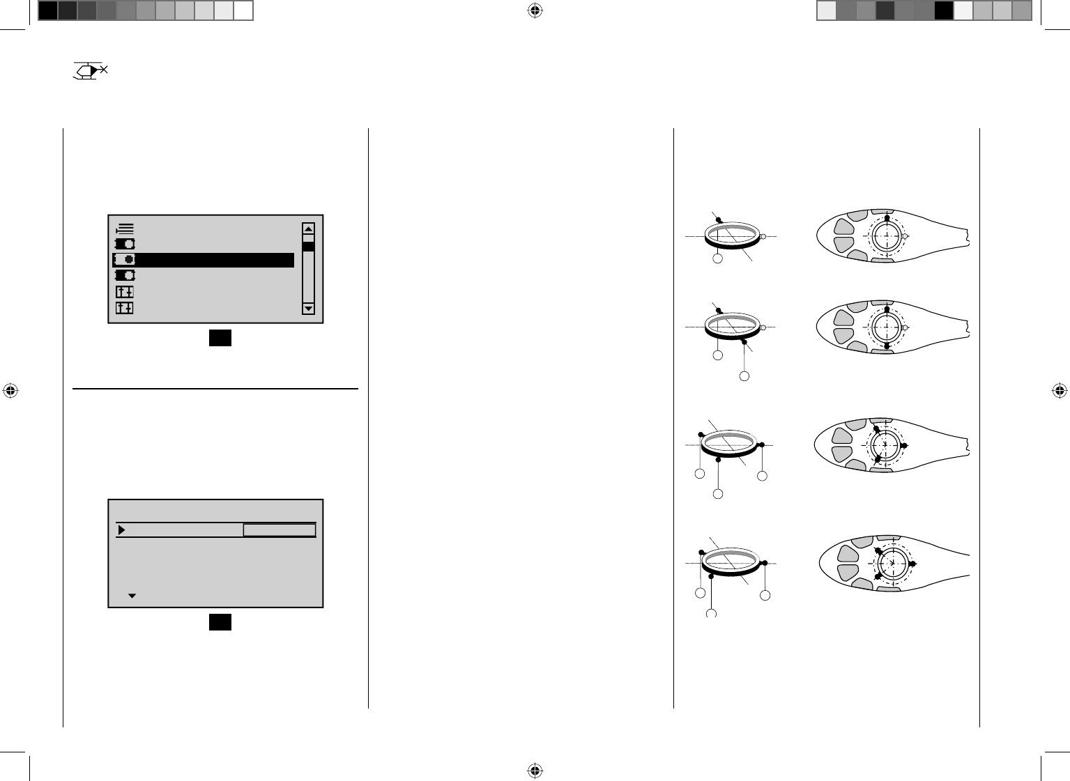
86 Detail program description - Helicopter type
Helicopter type
Establishing helicopter model type
This "Model type" menu is used to establish the
type of model to be programmed. This also activates
all characteristic mixers, coupling functions, etc.
in preparation for subsequent programming of the
specifi ed model type.
Suppress models
Base setup model
Servo adjustment
Control adjust
Helicopter type
Stick mode
Press briefl y on the center SET button in the right touch
pad.
Swashplate type
Control of the swashplate will require an appropriate
program variant which corresponds to the number of
servos operating pitch control.
After selecting the "Swashplate" line with the
cd arrow keys of the left or right touch pad, the
corresponding entry fi eld will be framed.
Linear. swashpl.
Swashplate
no
1 Servo
Rotor direct right
HELI TYPE
Pitch min. back
SEL
Press briefl y on the center SET button in the right touch
pad. The current setting for number of pitch servos will
be displayed in inverse video. Now choose the variant
needed with the arrow keys of the right touch pad.
"1 Servo": The swashplate will be tipped with one
servo each for roll and nick. Pitch control
will be affected by a separate servo.
(Since helicopter models operated
with only 1 pitch servo will be operated
WITHOUT the transmitter's mixer
functions for pitch, nick and roll, the
"Swashplate mixer" menu item in the
Multifunction menu will be hidden.)
"2 Servos": Two roll servos will displace the
swashplate axially to affect pitch control;
nick control will be decoupled by a
mechanical compensation rocker.
"3Sv (2Roll)": Symmetrical three-point control of
the swashplate is affected at three
articulation points, each radially offset
from the others by 120°, which are
connected to one nick servo (at the
front orrear) and two roll servos (located
laterally at the left and right). All three
servos push the swashplate axially to
affect pitch control.
"3Sv (140)": Asymmetrical three-point control of
the swashplate is affected at three
articulation points connected to one nick
servo (rear) and two roll servos (front
left and right). All three servos push the
swashplate axially to affect pitch control.
"3Sv (2Nick)": Symmetrical three-point control as
described above but radially offset by
90°, one lateral roll servo and two nick
servos, front and rear.
"4Sv (90°)": Four-point swashplate control affected by
two roll servos and two nick servos.
Simultaneously pressing the cd or ef keys of the
right touch pad (CLEAR) will set the option back to
"1 Servo".
Swashplate type: 1 Servo
2
Swashplate type: 2 Servos
2
1
Swashplate type: 3 Servos (2 Roll)
3
1
2
Swashplate type: 3 Servos (140°)
3
1
2
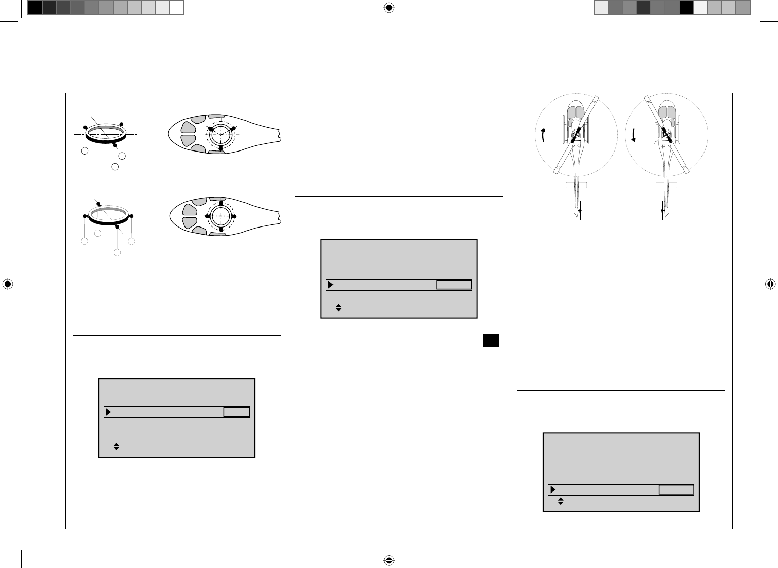
87
Detail program description - Helicopter type
Swashplate type: 3 Servos (2 Nick)
3
2
1
Swashplate type: 4 Servos (90°) 2 Nick / 2 Roll
2
5
1
3
Notice:
Except for the "1 Servo" choice, swashplate mixer
proportions must also be set in the "Swashplate mixer"
menu, page 196.
Swashplate linearizing
After selecting the "Linear. swashpl." line with the
cd arrow keys of the left or right touch pad, the
corresponding entry fi eld will be framed.
3Sv(2rol)
SEL
Linear. swashpl.
Swashplate
no
Rotor direct right
HELI TYPE
Pitch min. back
The "yes" entry will prevent undesired side effects
such as pitch change due to a roll function or tension
between swashplate servo rods.
This type of tension can arise when effected servos
strain for different displacement positions due to travel
which deviates from one another.
Linearizing will require a bit of familiarization on
the part of the pilot because, in order to linearize
the entire rotation travel for the servo arm, servo
travel can be appropriately reduced for small control
movements – similar to a substantial Expo setting – .
Rotor rotation
After selecting the "Rotor direct" line (rotor direction)
with the cd arrow keys of the left or right touch pad,
the corresponding entry fi eld will be framed.
3Sv(2rol)
SEL
Linear. swashpl.
Swashplate
no
Rotor direct right
HELI TYPE
Pitch min. back
Once the choice for main rotor rotation direction is made
with the arrow keys, it is set by pressing the center SET
button in the right touch pad.
"right": The main rotor turns clockwise when viewed
from above.
"left": The main rotor turns counter-clockwise when
viewed from above.
Simultaneously pressing the cd or ef keys of the
right touch pad (CLEAR) will set the option to "right".
right-hand
rotation
left-hand
rotation
This entry is necessary for correct operational
orientation of the torque and power compensation mixer
settings made in the "Helicopter mixer" menu:
Pitch,
C1 ¼ throttle,
C1 ¼ tail rotor,
Tail rotor ¼ throttle,
Roll ¼ throttle,
Roll ¼ tail rotor,
Pitch ¼ throttle,
Nick ¼ throttle,
Nick ¼ tail rotor.
Pitch min
After selecting the "Pitch min" (pitch minimum) line with
the cd arrow keys of the left or right touch pad, the
corresponding entry fi eld will be framed.
3Sv(2rol)
SEL
Linear. swashpl.
Swashplate
no
Rotor direct right
HELI TYPE
Pitch min. back
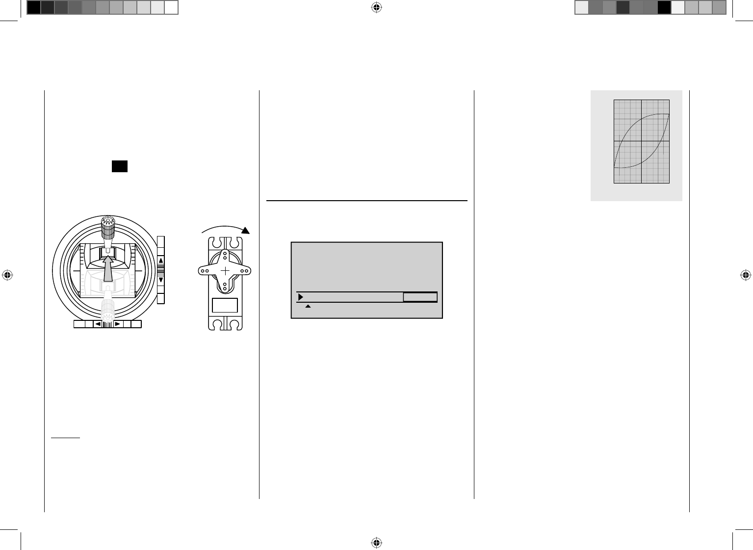
88 Detail program description - Helicopter type
The "Pitch min" line is used to adapt the direction of
operation for the throttle/pitch control stick to your
control preferences. All other helicopter program options
which involve throttle and pitch functions, e. g. throttle
curve, idle trimming, tail rotor mixer, etc., are dependent
on this setting.
Press the center SET button in the right touch pad.
The operating direction of the throttle/pitch joystick will
be displayed in inverse video. Now choose the variant
needed with the arrow keys of the right touch pad.
Pitch
These mean:
"fwrd.": minimum pitch setting when the pitch joystick
(C1) is "forward", i.e. away from the pilot.
"back": minimum pitch setting when the pitch joystick
(C1) is "back", i.e. toward the pilot.
Simultaneously pressing the cd or ef keys of the
right touch pad (CLEAR) will set this option to "rear".
Notices:
C1 trimming affects only the throttle servo. •
The so-called "throttle limiter" is set by default, see text •
beginning page 104, such that the throttle limiter for full
throttle can be set independently of the pitch servo via
input "Th.L.12" in the "Control adjust" menu.
Since your models will typically be operated with the •
same pitch-min direction, this specifi cation can be
conveniently preselected in the "transmitter-specifi c"
"Basic Settings" menu, page 224. This specifi cation
will be adopted automatically when a new model
memory is created in the "Helicopter type" menu but,
if desired, can be adapted on a model-specifi c basis
as described.
Expo throttle limit
After selecting the "Expo thro lim."line with the
cd arrow keys of the left or right touch pad, the
corresponding entry fi eld will be framed.
Expo thro lim. 0%
SEL
Linear. swashpl. no
Rotor direct right
HELI TYPE
Pitch min. back
The "Throttle limit" function, described in the text for the
"Control adjust" menu on page 104, can be assigned
an exponential characteristic curve.
A pitch progression rate value between -100 % and
+100 % can be set with the arrow keys.
For example, this is meaningful when the throttle limiter
is to be regulated in parallel with the idle setting. Further
details about the throttle limiter can be found in the text
for the "Control adjust" menu on page 100.
An example of two Expo throt-
tle limit curve characteristics
for 100 % servo travel.
continuous line:
negative expo values;
dashed line:
positive expo values
"
$
&
#
" $ &

89
Your notes
90 Detail program description - Servo adjustment
Column 3 "midpoint"
The servo midpoint setting is intended for adapting a
non-standard servo (a servo whose midpoint position
does not correspond to a pulse length of 1.5 ms, i.e.
1500 μs), as well as for minor adjustments, e. g. for the
fi ne tuning of the neutral position of model rudders.
Independent of trim levers and any mixer settings, the
neutral point can be set in a range of -125 % to +125 %
within a maximum servo travel scope of ±150 %.
Independent of all other trim and mixer settings, this
setting is always based directly on the respective servo.
Note that extreme adjustments of the neutral point can
lead to one-sided restrictions of servo motion because
both the electronic and the mechanical aspects limit
total travel to ±150 %.
Simultaneously pressing the cd or ef keys in
the right touch pad (CLEAR) will reset the entry fi eld
displayed in inverse video back to its "0 %" value.
Column 4 "- Weg +"
This column is used to set servo travel symmetrically or
asymmetrically for each side. The setting range is 0 …
150 % of normal servo travel. The values set are based
on the settings that have been made for the "midpoint"
column.
To create a symmetric
travel path, i. e. control-
side independent travel,
the respective control
(joystick, proportional
rotary control or switch) is
to be put into the position
which covers travel to
both sides of the marked
pad to complete the entry.
Simultaneously 6. pressing the cd or ef keys of
the right touch pad (CLEAR) will set any setting
which has been made back to the given default
value.
Important:
Servo designation numerals are based on the respective
receiver outputs to which they are connected, provided
that no swapping of transmitter and/or receiver outputs
has been specifi ed. This means that even a change of
stick mode will not effect the numbering of servos.
Column 2 "rev"
The direction in which a servo turns is adapted to the
practical reality of the given model so that the assembly
of control rods and joints do not need to accommodate
a specifi c servo rotation direction. Rotation direction is
symbolized by the "=>" and "<=" character combinations.
Servo rotation direction must be specifi ed before making
settings for the options which follow below.
Simultaneously pressing the cd or ef keys of the
right touch pad (CLEAR) will reset the rotation direction
to "=>".
normal
reversed
normal
reversed
This menu is used to set the direction, neutralization,
travel and limit parameters for a given selected servo
exclusively.
Suppress models
Base setup model
Control adjust
Model type
Servo adjustment
Stick mode
Briefl y press the center SET button in the right touch
pad.
S1
S2
S3
Rev cent +
trv
0%
0%
0%
100% 100%
100% 100%
100% 100%
0%
0%
100% 100%
100% 100%
S4
S5
Begin setting servo parameters in the left column.
Basic procedure steps:
Select the desired servo, S1 ... S12, with the 1. cd
arrow keys of the left or right touch pad.
If necessary, use the 2. ef arrow keys of the left or
right touch pad to reach the desired column then,
if desired, move the respective control out of its
midpoint to make an asymmetric setting.
Briefl y press the center 3. SET button in the right touch
pad. The respective entry fi eld will be displayed in
inverse video.
Use the 4. arrow keys of the right touch pad to set the
desired value.
Briefl y press the center 5. SET button in the right touch
Servo adjustment
Servo direction, midpoint, travel and limit
S
e
r
v
o
t
r
a
v
e
l
-
1
2
5
%
C
e
n
t
r
e
a
d
j
u
s
t
m
e
n
t
+
1
2
5
%
91
Detail program description - Servo adjustment
frame.
Notice:
It may be necessary to fi rst assign a control to a servo
attached to one of the 5 ... 12 control channels. If
necessary, this is to be done in the "Control adjust"
menu, see page 96 or 100.
To create an asymmetric travel path, the respective
control (joystick, proportional rotary control or switch) is
to be moved to the side to be set such that it covers only
the marked frame.
The value setting is activated by briefl y pressing the
center SET button in the right touch pad. The value
fi eld will be displayed in inverse video. Values can be
changed with the arrow keys of the right touch pad.
Pressing the center SET button in the right touch pad
will complete the entry.
Simultaneously pressing the cd or ef keys in
the right touch pad (CLEAR) will reset the changed
parameter in the entry fi eld back to 100 %.
Important:
In contrast to settings made with the "Control adjust"
menu, all settings made in this menu affect exclusively
the respective servo, independent of how the control
signal for this servo is produced, i.e. directly by a control
stick or by way of any mixer functions.
The adjacent fi gure
shows and example of
a side-dependent servo
setting, -50 % and
+150 %. Transmitter control travel
Servo travel
Column 5 "limit"
The "- lim +" column is reached by pushing the marked
frame with the f arrow key of the left or right touch pad,
analogous to the pointers at the bottom of the screen, to
the right beyond the "- trv +" column.
S1
S2
S3
Rev cent +
lim
0%
0%
0%
150% 150%
150% 150%
150% 150%
0%
0%
150% 150%
150% 150%
S4
S5
To create a symmetric, i. e. control-side independent
limit, the respective control (joystick, proportional rotary
control or switch) is to be put into the position in which
the marked frame covers both sides of the travel setting.
To set asymmetric travel, the respective control (joystick,
proportional rotary control or switch) is to be moved to
the side on which the marked frame only includes the
value to be changed.
Simultaneously pressing the cd or ef keys in
the right touch pad (CLEAR) will reset the entry fi eld
displayed in inverse video back to its "0 %" value.
Example:
A servo is controlled separately by two controls over a
mixer and but, for model-specifi c reasons, must only be
operated over a servo travel path of 100 % because, for
example, the rudder would mechanically collide with the
elevator if moved more than 100 %.
As long as only one control is used at a time, this is
no problem. But this does become a problem when
the signals of both controls (e. g. aileron and rudder)
combine to form an overall travel in excess of 100 %.
The linkage and servos could be strained excessively …
To prevent this, the travel should certainly be limited by
way of an individual travel limit. In the case of the rudder
used in the example, this would be a value slightly less
than 100 % – because it is assumed the rudder would
collide at 100 % – .
92 Detail program description - Joystick setting
Both joysticks are equipped for digital trimming. With
each brief push (one "click") on a joystick it will change
its neutral position by one increment. Holding the stick
longer will cause trimming to run in the corresponding
direction at increasing speed.
The current position is shown on the screen and
adjustment is also made "audible" by various high
frequency tones. This makes fi nding the mid-point during
fl ight easy, without looking at the screen. If the mid-point
is overrun, a brief motion pause will be inserted.
Current trim values are automatically stored when a
model memory change is made.
Furthermore – except for trimming the throttle/brake
joystick, commonly referred to as control function "C1"
(channel 1) – digital trimming is effective within a model
memory location selectively as either a global parameter
(i. e. consistent in all fl ight phases) or as a fl ight-phase
specifi c parameter. This specifi cation as "global"
or "phase" is made in the "Joystick setting" menu
described here, whereas C1 trimming is always made
"globally", i. e. independent of fl ight phases.
This setting is visualized in the base screen by a
"shadow" on trim bars:
shadow present = global,•
no shadow = fl ight phase dependent.•
The following fi gure shows elevator trim – in the right
column with standard Mode 1 – as being fl ight-phase
dependent.
Joystick setting
Setting stick mode 1 through 4
GRAUBELE
#01
2:22h
Stop
Flt
«Normal »
K78
0:00
0:00
5.5V
5.2V
M
HoTT
Scroll with the arrow keys of the left or right touch pad to
the "Stick mode" menu item of the multifunction menu.
Servo adjustment
Dual Rate / Expo
Stick mode
Channel 1 curve
Switch display
Control adjust
Open this menu item by pressing the center SET button
in the right touch pad.
Ch.1
Aile
Elev
Tr +
time
4
4
4
0.0s
0.0s
0.0s
40.0s
Rudd
0.0s
0.0s
0.0s
0.0s
GL
GL
GL
GL
St
This menu, adapted for winged models, permits the trim
effects of the four digital trim levers to be established
and control functions 1 through 4 to be selectively
"decelerated".
The desired line can be reached by using the arrow
keys of the left or right touch pad. Once the appropriate
function fi eld has been selected and then the center
SET button in the right touch pad is pressed briefl y, the
fi eld will appear in inverse video and the desired setting
can be made with the arrow keys of the right touch pad.
Column "Tr" (trim)
Except for "channel 1", this column can be used to
switchover trim effect from "GL(obal)" to "PH(ase)" and
vice versa. For example:
Tr +
4
4
4
0.0s
0.0s
0.0s
40.0s
0.0s
0.0s
0.0s
0.0s
GL
GL
GL
St
PH
Ch.1
Aile
Elev
time
Rudd
"GL": The position of the respective trim lever
is effective for the given model "globally",
i.e. across any fl ight phases which may be
programmed for it, page126.
"PH": The position of the respective trim lever is
effective on a phase-specifi c basis and will
be automatically stored upon change of fl ight
phase so that the setting is again available
following a return to this fl ight phase.
Simultaneously pressing the cd or ef keys of the
right touch pad (CLEAR) switches the entry back to
"GL".
Column "St" (trim steps)
The four digital trim levers push the neutral point of the
respective joystick by one increment for each press
("click"). This is where the increment size (step) can be
adjusted for a given direction, whereby maximum trim
travel, independent of the selected number of trim steps,
is always about ±30 % of control travel.
After selecting column "St" (Steps) and then the desired
trim control with the cd arrow keys of the left or right
93
Detail program description - Joystick setting
touch pad, the corresponding entry fi eld will be framed.
For example:
Tr +
4
4
4
0.0s
0.0s
0.0s
40.0s
0.0s
0.0s
0.0s
0.0s
GL
GL
GL
GL
St
Ch.1
Aile
Elev
time
Rudd
Briefl y press the center SET button in the right touch
pad. The current setting will be displayed in inverse
video. Now select the desired value, between 1 and 10,
with the arrow keys of the right touch pad. For example:
Tr +
4
4
0.0s
0.0s
0.0s
40.0s
0.0s
0.0s
0.0s
0.0s
GL
GL
GL
GL
St
8
Ch.1
Aile
Elev
time
Rudd
Simultaneously pressing the cd or ef arrow keys of
the right touch pad (CLEAR) will reset the change made
in the active fi eld back to "4".
Column "time"
The "time" column entries infl uence joystick acceleration
speed/s – if applicable, for each movement direction
for the four control sticks, 1 through 4, separately – .
This means that respective servos will then follow rapid
control position changes only at an accordingly delayed
rate. This time delay has a direct effect on the control
function and therefore also any servos controlled by this
function.
The time can be programmed symmetrically for both
sides or separate for each control direction. This setting
has a programmable range of 0 s to 9.9 s. In the case of
side-separate settings, the joystick is to be moved to the
respective side so that the inverse video fi eld will switch
between sides to the one for which the change is to be
made, – for example, even to ensure gentle rev-up of
the propulsion motor despite a (too) fast motion of the
C1 stick.
Tr +
4
4
4
0.0s
0.0s
40.0s
0.0s
0.0s
0.0s
0.0s
GL
GL
GL
GL
St
1.1s
Ch.1
Aile
Elev
time
Rudd
On the other hand, for reasons of safety, the motor cut-
off should always be "immediate".
Simultaneously pressing the cd or ef keys of the
right touch pad (CLEAR) will reset the change made to
the active fi eld back to "0.0 s".
94 Detail program description - Joystick setting | Helicopter model
Both joysticks are equipped for digital trimming. With
each brief push (one "click") on a joystick it will change
its neutral position by one increment. Holding the stick
longer will cause trimming to run in the corresponding
direction at increasing speed.
The current position is shown on the screen and
adjustment is also made "audible" by various high
frequency tones. This makes fi nding the mid-point during
fl ight easy, without looking at the screen. If the mid-point
is overrun, a brief motion pause will be inserted.
Current trim values are automatically stored when a
model memory change is made.
Furthermore – except for trimming the throttle/brake
joystick – digital trimming is effective selectively either as
a global parameter, i. e. consistent in all fl ight phases, or
as a fl ight-phase specifi c parameter. This specifi cation
as "global" or "phase" is made in the "Joystick setting"
menu described here, whereas throttle trimming is
always made "global" by software, i. e. independent of
fl ight phases.
This setting is visualized in the base screen by a
"shadow" on trim bars:
shadow present = global,•
no shadow = fl ight phase dependent.•
In the following fi gure nick trimming is used as an
example of fl ight-phase dependence – presented in its
default Mode 1 at the left – .
STARLET
#02
2:22h
Stop
Flt
«Normal »
K78
0:00
0:00
5.5V
5.2V
M
HoTT
Joystick setting
Setting stick mode 1 through 4
Scroll with the arrow keys of the left or right touch pad to
the " Stick mode " menu item of the multifunction menu.
Suppress models
Model select
Base setup model
Model type
Copy / Erase
Suppress menus
Open this menu item by pressing the center SET button
in the right touch pad.
Model select
Base setup model
Model type
Copy / Erase
Suppress models
Suppress: TOG
This menu, adapted for helicopter models, permits
the trim effects of the four digital trim levers to be
established and control functions 1 through 4 to be
selectively "decelerated".
The desired line can be reached by using the arrow
keys of the left or right touch pad. Once the appropriate
function fi eld has been selected and then the center
SET button in the right touch pad is pressed briefl y, the
fi eld will appear in inverse video and the desired setting
can be made with the arrow keys of the right touch pad.
Column "Tr" (trim)
These setting variations are confi gured to accommodate
the needs of helicopter models, which is why the following
alternative options are available for the "Thr." line:
Tr +
4
4
4
0.0s
0.0s
0.0s
40.0s
0.0s
0.0s
0.0s
0.0s
GL
GL
GL
St
PH
Ch.1
Aile
Elev
time
Rudd
"TL": "throttle limit"
C1 trimming operates as idle trimming when
the "throttle limit" function regulates the motor
for starting, see "Control adjust" menu,
page 104.
"AR": "autorotation throttle"
C1 trim operates as idle trim exclusively in the
"Autorot" fl ight phase.
This makes it possible to assign a principle
(fi xed) preset AR throttle position in the
"Helicopter mixer" menu, page 164, e. g. for
use during autorotation practice, which can be
"varied" with the idle trim lever.
Simultaneously pressing the cd or ef
keys of the right touch pad (CLEAR) will
switch this option back to "TL".
On the other hand, the trim effects of respective digital
trimming controls for the lines "Roll", "Nick" and "Tail
rotor" can be switched over from "GL" to "PH" and vice
versa. Example:
Tr +
4
4
4
0.0s
0.0s
0.0s
40.0s
0.0s
0.0s
0.0s
0.0s
GL
GL
St
PH
Thr.
Roll
Nick
time
Tail
TL
95
Detail program description - Joystick setting | Helicopter model
"GL": The position of the respective trim lever
is effective for the given model "globally",
i.e. across any fl ight phases which may be
programmed for it, page 126.
"PH": The position of the respective trim lever is
effective on a phase-specifi c basis and will
be automatically stored upon change of fl ight
phase so that the setting is again available
following a return to this fl ight phase.
Simultaneously pressing the cd or ef keys of the
right touch pad (CLEAR) will switch the entry back to
"GL".
Column "St" (trim steps)
The four digital trim levers push the neutral point of the
respective joystick by one increment for each press
("click"). This is where the increment size (step) can be
adjusted for a given direction, whereby maximum trim
travel, independent of the selected number of trim steps,
is always about ±30 % of control travel.
After selecting column "St" (Steps) and then the desired
trim control with the cd arrow keys of the left or right
touch pad, the corresponding entry fi eld will be framed.
Example:
Tr +
4
4
4
0.0s
0.0s
0.0s
40.0s
0.0s
0.0s
0.0s
0.0s
GL
GL
PH
St
Thr.
Roll
Nick
time
Tail
TL
Briefl y press the center SET button in the right touch
pad. The current setting will be displayed in inverse
video. Now select the desired value, between 1 and 10,
with the arrow keys of the right touch pad. For example:
Tr +
4
4
0.0s
0.0s
0.0s
40.0s
0.0s
0.0s
0.0s
0.0s
GL
GL
PH
St
8
Thr.
Roll
Nick
time
Tail
TL
Simultaneously pressing the cd or ef keys of the
right touch pad (CLEAR) will reset any change made to
the active fi eld back to "4".
Column "time"
The "time" column entries infl uence joystick acceleration
speed/s – if applicable, for each movement direction
for the four control sticks, 1 through 4, separately – .
This means that respective servos will then follow rapid
control position changes only at an accordingly delayed
rate. This time delay has a direct effect on the control
signal and therefore also commensurately on any servos
controlled by the effected controls.
The time can be programmed symmetrically for both
sides or separate for each control direction. This setting
has a programmable range of 0 s to 9.9 s. In this latter
case, the given stick control is to be moved to the
respective side so that the inverse video fi eld will switch
between sides to the one for which the change is to be
made.
Example:
All three servos are to be actuated for swashplate
pitch control, e g. a "Pitch" control movement for a "3Sv
(2Roll)" swashplate. However, travel for the middle
servo is greater than that of the other two servos on the
shorter lever.
A rash "Pitch" control movement would not operate
the nick servo in the middle as quickly as it would the
two roll servos on the shorter lever. This would cause
a momentary control motion in the "nick" direction.
However, if response time for the "pitch" control function
were to be reduced by at least the positioning time for
the servo in the middle then all three servos would reach
their proper positions at the same time. The necessary
delay times typically amount to only a few tenths of a
second. For example:
Tr +
4
4
8
0.0s
40.0s
0.0s
0.0s
0.0s
TA
GL
GL
PH
St
0.0s
0.2s
0.2s
Thr.
Roll
Nick
time
Tail
Simultaneously pressing the cd or ef keys of the
right touch pad (CLEAR) will reset any change made to
the active fi eld back to "0.0 s".
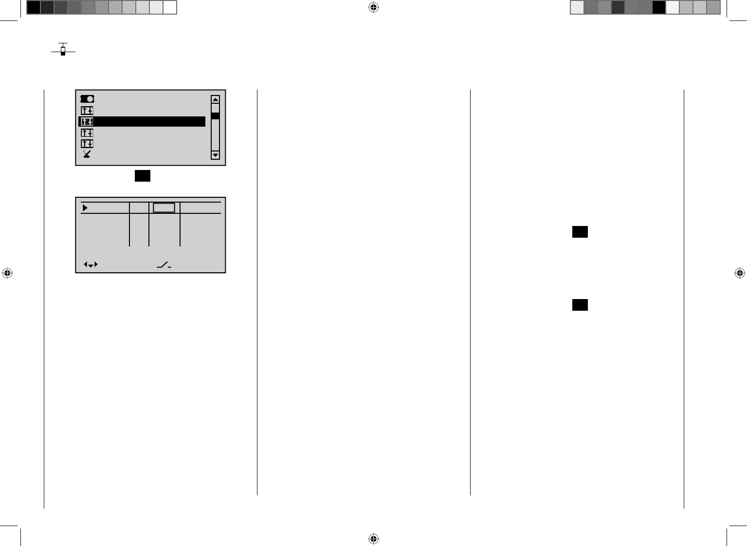
96 Detail program description - Control adjust
Control adjust
Fundamental operating steps for control and switch assignments
Servo adjustment
Dual Rate / Expo
Stick mode
Channel 1 curve
Switch display
Control adjust
Briefl y press the center SET button in the right touch
pad.
Input 5
offset
0%
0%
0%
–––
0%
Input 6
Input 7
Input 8 –––
–––
–––
GL
GL
GL
GL
typ
normal
Aside from the two joysticks which operate control
functions 1 through 4, a standard mc-32 HoTT
transmitter is also equipped with other operating
elements:
two 3 position switches: SW 4/5 or CTRL 9 and SW •
6/7 or CTRL 10. These are assigned in this menu as
"Ct9" and "C10".
three proportional rotary controls: CTRL 6, 7 and 8. •
Respectively designated "Ct6", "Ct7" and "Ct8" in the
menu.
three 2 position switches: SW 2, 3 and 8. •
Respectively displayed in the menu as "2", "3" and
"8" in combination with a switch symbol indicating the
switching direction.
two pushbutton switches: SW 1 and SW 9. Analogous •
to the aforementioned switches; designated as "1"
and "9" and displayed in combination with a symbol
indicating switching direction.
In contrast to the two joysticks which, when initialized
for a new model memory as a "Winged aircraft" model
type will already be confi gured to operate the servos
connected to receiver outputs 1 … 4, these "other"
operating elements initially remain inactive.
Thus, at least in the system's delivered state, – as
already mentioned on page 20 – or even after the
initialization of a new model memory with the "Winged
aircraft" model type and its "binding" to the intended
receiver, only those servos connected to the two
joysticks by way of receiver outputs 1 … 4 are able to
be operated; any servos which may be connected to the
receiver's outputs 5 … 12 will initially remain inactive in
their middle positions.
Even though this may seem inconvenient at fi rst glance,
it is indeed just this state which offers full freedom to
select and assign these "other" operating elements as
desired and leaves any unused operating elements
harmlessly dormant without taking any action to
deactivate them. This has the advantage that:
An unused operating element will have no infl uence
on your model's operation even if inadvertently
operated; it will be inactive and therefore have no
assigned function.
These "other" operating elements can be freely
assigned to meet your needs and the features of your
model. They can be assigned to any function input in
the "Control adjust" menu, see page 50. But this also
means that each of these operating elements can also
be assigned to multiple functions at the same time.
For example, one and the same toggle switch, SW
X, assigned in this menu to an input, can at the same
time be assigned to a "timer" as an On/Off switch in the
"Timers (general)" menu...
Furthermore, all inputs can be selectively made global
or fl ight-phase specifi c (providing that fl ight phases have
been defi ned in the menus "Phase settings", page 128,
and "Phase assignment", page 134). The respective
names for the given fl ight phases will then appear in the
bottom screen line, e. g. "normal".
Basic procedure steps
Select the desired input, E5 ... 12 with the 1. cd arrow
keys of the left or right touch pad.
If necessary, use the 2. ef arrow keys of the left or
right touch pad to change to the desired column.
Briefl y 3. press the center SET button in the right touch
pad. The respective entry fi eld will be displayed in
inverse video.
Actuate the desired operating element or use the 4.
arrow keys of the right touch pad to set the desired
value.
Briefl y5. press the center SET button in the right touch
pad to complete the entry.
Simultaneously6. pressing the cd or ef arrow
keys of the right touch pad (CLEAR) will reset any
setting change back to its default value.
97
Detail program description - Control adjust
Column 2 "typ"
Analogous to the "Stick mode" menu already described,
this column can be used to select whether other settings
are to be made for the given input, e. g. "GL(obal)" or
"PH(ase specifi c)" and vice versa.
Input 5
offset
0%
0%
0%
–––
0%
Input 6
Input 7
Input 8 –––
–––
–––
GL
GL
GL
GL
typ
normal
"GL": The given input's settings will be "globally"
effective for the respective model memory
across any fl ight phases which may be
programmed.
"PH": The settings for this input will be effective on
a fl ight-phase basis and must therefore be
explicitly set in each fl ight-phase where it is to
be effective.
Notice:
More about fl ight phases on page 126.
Column 3 "Control or switch assignment"
Use the cd arrow keys of the left or right touch pad to
select one of the inputs, 5 through 12.
Briefl y press the center SET button in the right touch
pad to activate the assignment.
Input 5
offset
0%
0%
0%
–––
0%
Eing. 6
Eing. 7
Input 8 –––
–––
–––
GL
GL
GL
GL
typ
Move desired switch
or control adj.
Normal
Now activate the desired control (CTRL 6 through 10)
or selected switch (SW 1 through 3, or 8 or 9) - whereby
a proportional rotary control will only be detected after
some "detenting" action has taken place and so may
have to be activated a bit longer. If adjustment travel is
insuffi cient, activate the control in the other direction.
Two position switches can only switch back and forth
between their fi xed end states, e. g. motor ON or OFF.
On the other hand, the 3 position switches, SW 4/5 or
6/7, that can be incorporated in this "Control adjust"
menu as "Ct9" or "C10", also offer a middle position.
Simultaneously pressing the cd or ef keys of the
right touch pad (CLEAR) for an active control or switch
assignment – see fi gure above – will reset the input back
to its "free" state.
Tips:
When assigning switches, pay attention to the •
desired switching direction and also that all unused
inputs remain "free" or are again reset to "free" (if
applicable, across all fl ight phases). This is necessary
to ensure that inadvertent actuations of these unused
controls cannot cause malfunctions.
The travel setting described below allows the •
appropriate end state to be established for an
assigned switch.
For example, the screen will now show either the
control's number or – in conjunction with a switch
symbol indicating the switching direction – the switch's
number .
Input 5
offset
0%
0%
0%
–––
0%
Input 6
Input 7
Input 8 –––
GL
GL
GL
GL
typ
Ct6
3
Normal
Column 4 "offset"
The control midpoint for the given control, i. e. its zero
point, can be changed in this column. The adjustment
range lies between -125 % and +125 %.
Input 5
offset
0%
0%
0%
–––
0%
Input 6
Input 7
Input 8 –––
GL
GL
GL
GL
typ
Ct6
3
Normal
Simultaneously pressing the cd or ef keys in
the right touch pad (CLEAR) will reset the entry fi eld
displayed in inverse video back to "0 %".
Column 5 "-travel+"
This column is used to set servo travel symmetrically or
asymmetrically for each side. The setting range is ±125 %
of normal servo travel.
Use the cd arrow keys of the left or right touch pad to
select one of the inputs, 5 through 12.
To set symmetric travel, i. e. control-side independent
travel, the respective operating element (proportional
rotary control or switch) is to be put into a position which
98 Detail program description - Control adjust
covers travel to both sides of the marked frame.
Input 5
–travel+
+100%
+100%
+100%
+100%
Input 6
Input 7
Input 8
+100%
+100%
+100%
+100%
Normal
To set asymmetric travel, the respective control
(proportional rotary control or switch) is to be moved to
the side on which the marked frame only includes the
value to be changed.
Input 5
–travel+
+100%
+100%
+100%
+100%
Input 6
Input 7
Input 8
+100%
+100%
+100%
+100%
Normal
The value setting is activated by briefl y pressing the
center SET button in the right touch pad. The value
fi eld will be displayed in inverse video. Values can be
changed with the arrow keys of the right touch pad.
Input 5
–travel+
+100%
+100%
+100%
Input 6
Input 7
Input 8
+100%
+100%
+100%
+111%+111%
Normal
Input 5
–travel+
+100%
+100%
+100%
Input 6
Input 7
Input 8
+100%
+100%
+100%
+88%+111%
Normal
Another brief press of the center SET button in the right
touch pad will complete the entry.
Negative and positive parameter values are possible in
order to appropriately adapt the control's direction or
effect.
Simultaneously pressing the cd or ef keys in
the right touch pad (CLEAR) will reset the changes
parameter in the inverse video entry fi eld back to
+100 %.
Important:
In contrast to the servo travel setting, control travel
setting effects all derived mixer and coupling functions,
i. e. infl uences all servos which can be actuated by way
of the respective control.
Column 6 "time"
A symmetric or asymmetric time delay between 0 and
9.9 s can be applied to each of the 5 ... 12 function
inputs.
Use the f arrow keys in the left or right touch pad to
push the marker frame to the right, beyond the "-travel+"
column.
To set a symmetric, (i. e. control-side independent) time
delay, the respective operating element (proportional
rotary control or switch) must be put into a position
which covers time to both sides of the marked frame.
Input 5
– time +
0.0
0.0
0.0
0.0
Input 6
Input 7
Input 8
0.0
0.0
0.0
0.0
Normal
To set an asymmetric time delay, the respective control
(proportional rotary control or switch) is to be moved to
the side on which the marked frame only includes the
value to be changed.
Input 5
– time +
0.0
0.0
0.0
0.0
Input 6
Input 7
Input 8
0.0
0.0
0.0
0.0
Normal
Notice:
Further suggestions for structuring timed fl ows can be
found in the section "Control of timed fl ows" on page 266.

99
Detail program description - Control adjust
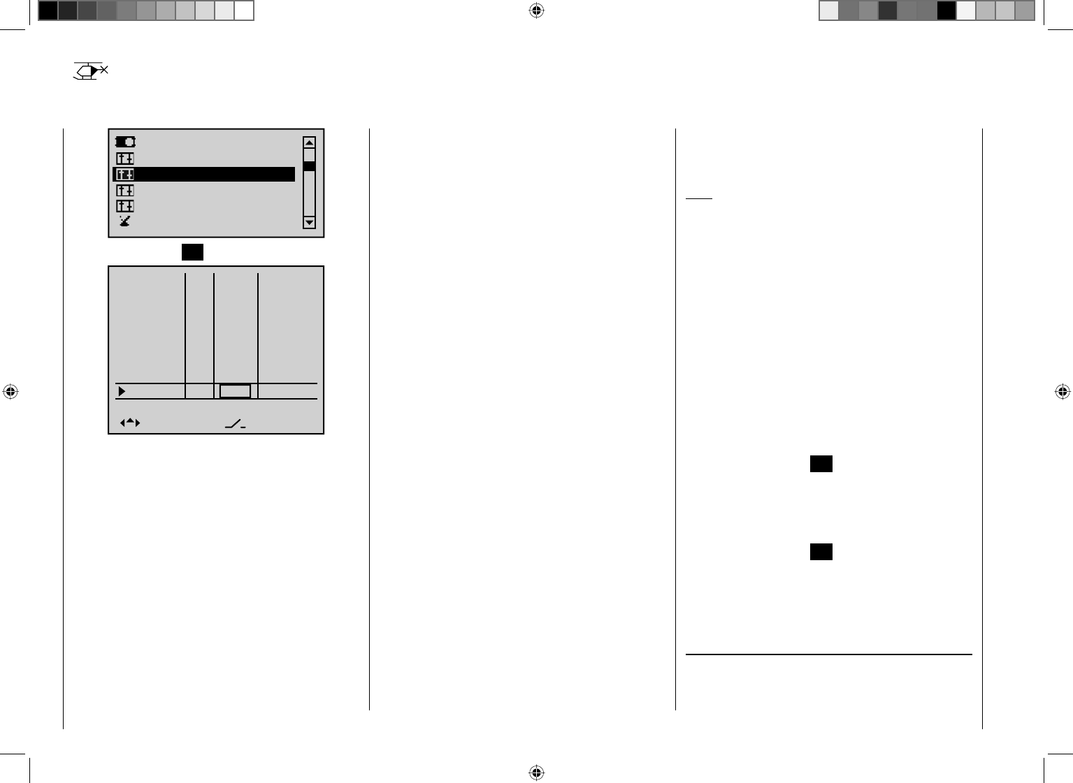
100 Detail program description - Control adjust
Control adjust
Basic procedure for transmitter control and switch assignment
Servo adjustment
Dual Rate / Expo
Stick mode
Channel 1 curve
Switch display
Control adjust
Briefl y tap the center SET key on the right touch pad:
Input 5
offset
0%
0%
0%
Throt
Gyro
Input 8 –––
–––
–––
6
7
Input 9
Input10
Input11
Th.L.12
–––
–––
–––
Ct6
0%
0%
0%
0%
0%
–––
GL
GL
GL
GL
GL
GL
GL
GL
typ
In addition to the two dual axis sticks for control
functions 1 to 4, the mc-32 HoTT transmitter is
equipped with other controls as standard:
Two 3-stage switches: SW 4/5 and CTRL 9, plus SW •
6/7 and CTRL 10. On this menu, these are assigned
as "Ct9" and "Ct10".
Three proportional rotary controls: CTRL 6, 7 and 8. •
Named as "Ct6", "Ct7" and "Ct8" on this menu.
Three 2-stage switches: SW 2, 3 and 8. Labeled •
accordingly as "2", "3" and "8" on the menu. A switch
icon indicating the switch direction is also shown.
Two push-button switches: SW 1 and SW 9. •
Displayed as with the preceding switches, "1" and "9"
with a switch icon indicating the switch direction.
Even with a newly-initialized model memory for the
"Helicopter" model type, the two dual axis sticks will – in
the absence of further confi guration – infl uence only
those servos connected to receiver outputs 1 … 4 and
6. Unlike these, the "additional" transmitter controls
mentioned above are theoretically inactive at fi rst. (The
exception here is the CTRL 6 proportional rotary control
(throttle limiter), which also affects servo 6.)
One of the effects of this is that (as mentioned back
on page 20 ) with a factory-fresh unit, only the servos
connected to receiver outputs 1 … 4 and –depending on
the position of the throttle limiter– servo 6 can be moved
using the two joysticks. (This also applies following
the initialization of a new model memory with the
"Helicopter" model type and its "binding" to the receivers
to be installed in the model.) The servos connected
to slots 5, 7 and 8, on the other hand, will simply stay
"stuck" at their center points.
While this may appear more than a little awkward at
fi rst glance … this is the only way to ensure that you
can select any of the "additional" transmitter controls
as you wish and, in addition, do not need to waste time
"disabling" control elements you do not require. This is
because
the only way to ensure an unwanted control element
has no effect on your model, even if operated by
accident, is to make it inactive, i.e. unassigned to a
function.
You can therefore use this "Control adjust" menu
exactly as you wish, to assign the "additional" control
elements as you want to any required function input; for
further details, see page 50. Equally, this also means
that you can assign individual transmitter controls to
multiple functions at the same time, if required. As an
example: the exact same rocker switch SW X that you
assign to an input on this menu can simultaneously be
assigned to "Timers" on the "Timers (general)" menu
as an "On/Off" switch, etc.
Note:
As a rule, input 6 must kept "free" for a helicopter model.
On this, see "Throttle" on the next double page.
Furthermore, if fl ight phases have been defi ned on
the "Phase settings" menu (page 128) and "Phase
assignment" menu (page 134), then all inputs must be
set either as global or fl ight phase-specifi c. The names
assigned to each of these fl ight phases are then shown
in the bottom line of the screen display, e. g. "Normal".
Basic procedure
Using the arrow keys 1. cd on the left or right touch
pad, select the input you want: Input 5, Throt 6, Gyro
7, Input 8 … 11 or Th.L.12.
If necessary, use the arrow keys 2. ef on the left or
right touch pad to select the column you want.
Briefl y tap the center 3. SET key on the right touch pad.
The corresponding input fi
eld is shown highlighted.
Activate your chosen transmitter control or use 4. the
arrow keys on the right touch pad to set your chosen
value.
Briefly tap the center 5. SET key on the right touch pad
to complete data entry.
If you 6. tap the cd or ef keys on the right touch
pad at the same time (CLEAR), this will reset any
settings made back to their respective default values.
Column 2, "typ"
Similarly to the "Stick mode" menu described
previously, this column can be used to defi ne whether
further settings for the input in question are to have a
101
Detail program description - Control adjust
Column 4, "offset"
In this column, you change the control center, i. e. the
zero point, for the transmitter control in question. The
adjustment range lies between -125 % and +125 %.
Input 5
offset
0%
0%
0%
–––
0%
Throt
Gyro
Input 8
–––
GL
GL
GL
GL
typ
Normal
6
7Ct7
3
If you tap the cd or ef keys on the right touch pad
(CLEAR) at the same time, this will reset the value in
the highlighted fi eld back to 0%.
Column 5, "–travel+"
This column is used to set servo travel symmetrically or
asymmetrically for each side. The setting range is ± 125 %
of normal servo travel.
Using the arrow keys cd on the left or right touch pad,
select an input: Input 5, Throt 6, Gyro 7, Input 8 … 11 or
Th.L.12.
To confi gure symmetrical travel, i. e. one independent of
the control side, move the affected transmitter control
(proportional rotary control or switch) to a position at
which the marker frame encloses both sides of the travel
adjustment region:
–travel+
+100%
+100%
+100%
+100%
+100%
+100%
+100%
+100%
Normal
Input 5
Throt
Gyro
Input 8
6
7
"GL(obal)" or a "PH(ase-specifi c)" effect, as follows:
Input 5
offset
0%
0%
0%
–––
0%
Throt
Gyro
Input 8 –––
–––
–––
GL
GL
GL
GL
typ
Normal
6
7
"GL": The settings for the input in question affect all
fl ight phases programmed (if any) and thus act
"globally" on the model memory in question.
"PH": The settings for this input take effect per
fl ight phase and must therefore be confi
gured
separately for each fl ight phase.
Note:
See page 128 for more information on fl ight phases.
Column 3, "Transmitter control/switch assignment"
Using the arrow keys cd on the left or right touch pad,
select an input: Input 5, Throt 6, Gyro 7, Input 8 … 11 or
Th.L.12.
Briefl y tap the center SET key on the right touch pad to
activate the assignment option:
Input 5
offset
0%
0%
0%
–––
0%
Gas
Gyro
Input 8 –––
–––
–––
GL
GL
GL
GL
typ
Normal
6
7
Move desired switch
or control adj.
Now move your chosen transmitter control (CTRL 6
to 10) or selected switch (SW 1 to 3, 8 and 9). Note,
however, that the proportional rotary controls are only
identifi ed after a few "turns": this means you need to
move them for slightly longer. If the control does not
have enough travel, move the control in the opposite
direction as required.
Once assigned, the 2-stage switches can be switched
back and forth only between their respective end-
points, e. g. headlights ON/OFF. In contrast, the 3-stage
switches SW 4/5 and 6/7 also permit a center control
position; these are confi gured as "Ct9" or "Ct10" on the
"Control adjust" menu.
If a switch has been assigned, then tapping the cd
or ef keys on the right touch pad at the same time
(CLEAR) bei aktivierter Schalterzuordnung – see screen
image above – will reset the input back to "free".
Tips:
When assigning switches, pay attention to the •
desired switching direction and also that all unused
inputs remain "free" or are again reset to "free" (if
applicable, across all fl ight phases). This is necessary
to ensure that inadvertent actuations of these unused
controls cannot cause malfunctions.
The travel setting described below allows the •
appropriate end state to be established for an
assigned switch.
The screen now shows either the control number
or – alongside a switch icon that shows the switch
direction – the switch number, e. g.:
Input 5
offset
0%
0%
0%
–––
0%
Throt
Gyro
Input 8
–––
GL
GL
GL
GL
typ
Normal
6
7Ct7
3
102 Detail program description - Control adjust
To confi gure asymmetric travel, move the affected
transmitter control (proportional rotary control or switch)
to the side on which you wish to confi gure it, so the
marker frame encloses only the value you want to adjust:
–travel+
+100%
+100%
+100%
+100%
+100%
+100%
+100%
+100%
Normal
Input 5
Throt
Gyro
Input 8
6
7
Briefl y tap the center SET key on the right touch pad
to activate value confi guration: The value fi eld is shown
highlighted. Use the arrow keys on the right touch pad to
change the values:
–travel+
+100%
+100%
+100%
+100%
+100%
+100%
+111%+111%
Normal
Input 5
Throt
Gyro
Input 8
6
7
–travel+
+100%
+100%
+100%
+100%
+100%
+100%
+88%+111%
Normal
Input 5
Throt
Gyro
Input 8
6
7
Complete the confi guration by tapping the center SET
key on the right touch pad.
Negative and positive parameter values are possible in
order to appropriately adapt the control's direction or
effect.
If you tap the cd or ef keys on the right touch pad
(CLEAR) at the same time, this will reset parameters
changed in the highlighted fi eld back to +100%.
Important:
In contrast to altering servo travel, changing the control
travel setting affects all "downstream" mixer and
coupling inputs, i. e. any and all servos that could be
actuated by the transmitter controls concerned.
Column 6, "– time +"
Each of the function inputs 5 … 12 can be assigned a
symmetrical or asymmetric time delay of between 0 and
9.9. s.
Using the arrow key f on the left or right touch pad,
move the marker frame over the "– travel +" column and
to the right.
To confi gure a symmetrical time delay, i. e. one
independent of the control side, move the affected
transmitter control (proportional rotary control or switch)
as necessary to a position at which the marker frame
encloses both sides of the time adjustment region:
– time +
0.0
0.0
0.0
0.0
0.0
0.0
0.0
0.0
Normal
Input 5
Throt
Gyro
Input 8
6
7
To confi gure an asymmetric time delay, move the
affected transmitter control (proportional rotary control
or switch) as required to the side on which you wish
to confi gure it, so the marker frame encloses only the
value you want to adjust:
– time +
0.0
0.0
0.0
0.0
0.0
0.0
0.0
0.0
Normal
Input 5
Throt
Gyro
Input 8
6
7
Note:
Other suggestions for designing timed sequences
can be found under "Controlling timed sequences" on
page 266.
103
Detail program description - Control adjust
"Throt 6"
Input 5
offset
0%
0%
0%
–––
0%
Throt
Gyro
Input 8 –––
–––
–––
GL
GL
GL
GL
typ
Normal
6
7
In the helicopter program, it is also theoretically possible
to assign any transmitter control (rotary proportional
controls and switches) to individual inputs.
However, please note here that some of the inputs
available on this menu are already assigned to
helicopter-specifi c functions, and therefore cannot be
re-assigned in this way.
If we consult the receiver assignment table on page 59,
for example, we see that the throttle servo (or speed
controller of an electrically-powered helicopter) must be
connected to receiver output "6", since control channel
"6" is reserved for motor power control.
Unlike a fi xed-wing model aircraft, however, the throttle
servo or speed controller is not directly controlled by
the throttle stick or other transmitter control, but by a
complex mixer system – see the "Helicopter mixers"
menu (from page 164). Furthermore, the "Throttle limit
function" described on the next page also infl uences this
mixer system.
Assigning a transmitter control or switch on the
"Throttle" line, or to its supplementary control signal,
would unnecessarily "confuse" this complex mixer
system. For this reason the "Throttle" input MUST be
left "free".
" Gyro 7"
Input 5
offset
0%
0%
0%
–––
0%
Throt
Gyro
Input 8 –––
–––
–––
GL
GL
GL
GL
typ
Normal
6
7
Most of the latest gyro systems not only feature infi nitely
variable proportional gyro gain setting, but also offer
a choice of two separate types of gain mode on the
transmitter.
If the gyro you are using also has this feature, then
this menu option gives you the opportunity to specify
both "normal" gyro gain and, as appropriate, to specify
"heading-lock mode" in the "Offset" column in the
range of ±125%, plus a particular gain type within this
pre-selection, so as to be able to exploit maximum
stabilization for normal, slow fl ight, but to reduce gyro
gain for fast circuits and aerobatics.
To proceed as described above, use fl ight phase
switching to enter different settings on the "Gyro" line.
From the starting-point of these
predefi ned – static – fl ight phase-specifi c settings, you
can then use a transmitter control assigned to the "Gyro
7" line, e. g. one of the rotary potentiometers CTRL 7
or 8, to vary the gyro gain around the respective "offset
point": The center point of the control corresponds to
the setting specifi ed by the offset. If the transmitter
control is moved from this center point in the direction
of full travel, gyro gain increases proportionally; it
diminishes when moved in the opposite direction. This
provides a fast and straightforward method of adjusting
gyro gain even in flight – e. g. to suit changing weather
conditions – or to test-fl y optimum settings. In software
terms you can even limit the gyro gain range in both
directions by adjusting transmitter control travel.
In this context, ensure that you comply with the
instructions on adjusting your gyro: if not, you
risk making adjustments that render your heli
impossible to fl y.
Adjusting the gyro sensor
To achieve the maximum possible level of stabilization
for the helicopter with the gyro along the vertical axis,
observe the following:
The controls should have as little friction and "play" •
as possible.
There should be no "spring" in the control linkage.•
Use a strong and – in particular – a fast servo. •
When the gyro sensor detects a model rotation, the
faster its response – a corresponding corrective change
to tail rotor thrust – takes effect, the further the gyro
gain adjustor can be moved without causing the tail of
the model to start oscillating, and the better the model's
stability about its vertical axis. If the response is slower,
there is a risk that the model's tail will start to oscillate
even at low gyro gain settings. Here, further reductions
to gyro gain will need to be made – either by using the
default value under "Gyro" or the associated transmitter
control – to eliminate the oscillation.
If the model is fl ying forward at high speed or hovering
in a powerful headwind, the net result of the stabilizing
effect of the vertical fi n combined with the gyro may
also lead to an overreaction that once again manifests
itself through tail oscillation. To achieve optimum gyro
stabilization under all conditions, you should make use
of the option to adjust gyro gain from the transmitter
104 Detail program description - Control adjust
control using either the CTRL 7 or 8 proportional rotary
control.
"Thr.l 12"
As standard, the "Thr.l 12" input is assigned to the CTRL
6 proportional rotary control mounted on the top left of
the transmitter.
Input 9
offset
0%
0%
0%
–––
0%
Input
Input
Th.L.12 Ct6
–––
–––
GL
GL
GL
GL
typ
Normal
10
11
This pre-assignment makes it unnecessary to program
the two fl ight phases that may be familiar to you from
using other remote control systems – namely "with
idle-up" and "without idle-up"" – ,since the mc-32
HoTT program offers a much more fl exible approach to
fi ne-tuning and optimizing increases to system rotational
speed below the hover point than "idle-up". If you
nonetheless prefer to program your helicopter "with idle-
up", then deactivate the "throttle limit" function described
below by setting input "Thr.l 12" to "free".
Meaning and application of "throttle limit"
As already mentioned under "Throttle", and in contrast
to fi xed-wing models, the power output of a helicopter's
drive system is not controlled directly using the C1
joystick, but only indirectly via the throttle curve settings
on the "Helicopter mixers" menu or – if your model
features a speed governor – by using this mechanism.
Note:
For separate fl ight phases, you can of course use fl ight
phase programming to set specifi c throttle curves.
Nevertheless, both methods of output control de facto
result in the helicopter carburetor never approaching
Throttle limit function
anything near its idle speed under "normal" fl ight
conditions, and that the motor can therefore neither be
started or stopped cleanly without some other means of
intervention.
The "throttle limit" feature resolves this problem
elegantly by using a separate transmitter control – by
default the CTRL 6 proportional control mounted on the
top left of the transmitter – to limit the throttle servo or
the output level of the speed controller. In this way, it is
possible to use the throttle limit control to "throttle back"
as you wish as far as the idle setting – at which point
the trim lever on the throttle/collective pitch stick takes
over – or to cut out an electrical drive system directly.
Conversely, the throttle servo or speed controller can
only open up to its full-throttle position if the throttle limit
control has also released the full servo travel path.
The value set on the (right-hand) plus side of the "travel"
column must therefore always be set to high enough
to ensure that the maximum setting of the throttle limit
control never restricts the full-throttle position that can
be obtained using throttle curve settings – which typically
means setting a value in the range +100% to 125%.
–travel+
+100%
+100%
+100%
+100%
+100%
+100%
+100%
Normal
Input 9
Input10
Input
Th.L.12 +125%
11
The value on the (left-hand) minus side of the "travel"
column should be set so that the throttle limit control
can be used to safely cut out an electrical drive system
or close a carburetor down far enough that the glow
motor can also be cut out in conjunction with the
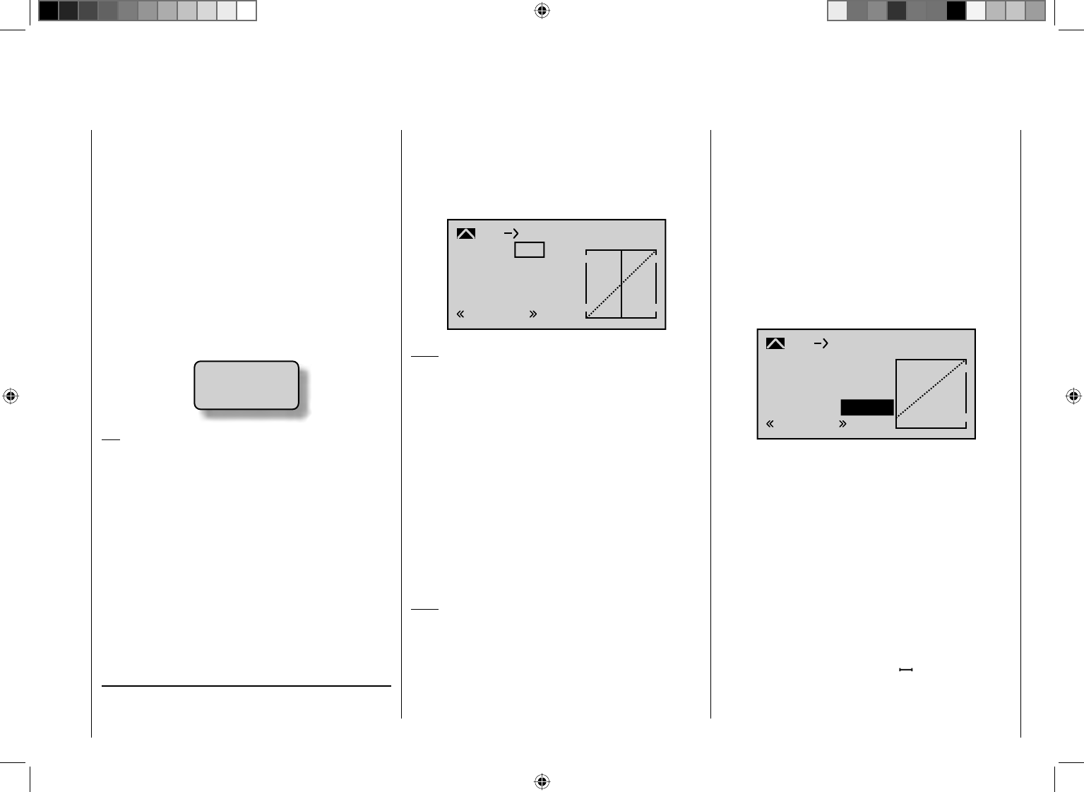
105
Detail program description - Control adjust
the – digital – C1 trim. You should thus (initially) leave this
value at +100%.
Furthermore, this variable "limiting" of throttle travel not
only gives you a convenient method for starting and
stopping the motor, but may also prove to have added
a not inconsiderable increase in safety! For example,
just imagine what could happen if you were carrying the
helicopter to the take-off site with the motor running and
you accidentally moved the C1 stick …
Accordingly, if the carburetor or speed controller is open
too far, an audible warning is heard as soon as you turn
on the transmitter, and the message below is shown on
the basic display:
Throttle
too
high !
Tip:
You can use the "Servo display" menu to observe
the infl uence of the throttle limit slider. This menu
can be accessed from almost any other menu by
simultaneously pressing the ef keys on the left touch
pad. Bear in mind that servo output 6 controls the
throttle servo on the mc-32 HoTT!
Basic idle setting
Start by turning the throttle limiter – by default the
CTRL 6 proportional rotary control on the top left of the
transmitter – clockwise as far as it will go. Set the throttle/
collective pitch stick to the maximum pitch position and
also check the submenu "C1 ¼ Thr" on the menu …
"Helicopter mixers" (pages 164 … 179)
… to ensure you have an active standard throttle curve.
If, for example, the standard throttle curve has already
been changed following the initialization of a model
memory, then this must be reset at least temporarily to
the values "Point 1 = -100%", "Point 3 = 0%" and "Point
5 = +100%":
Input
Output
Point ?
0%
0%
–100%
C1
Normal
Thr
Curve off
Note:
As the throttle trim lever has no effect if the throttle
limiter is open, its position here is unimportant.
Now – without starting the glow motor – adjust the
throttle servo, preferably mechanically and optionally
using the servo 6 travel adjustment option in the
"Servo adjustments" menu, so that the carburetor is
completely open.
Now, close the throttle limiter completely by turning the
CTRL 6 proportional rotary control in an anti-clockwise
direction as far as it will go. Use the trim lever on the
throttle/collective pitch stick to move the trim position
marker to the "Motor OFF" position – see the fi gure in
the next column.
Note:
In contrast, when the throttle limiter is closed,
the position of the throttle/collective pitch stick is
meaningless. It can therefore remain at the maximum
collective pitch position so that, when adjusting
carburetor linkages, the throttle limiter alone can be
used to switch between full throttle (throttle limiter open)
and "Motor OFF" (throttle limiter closed).
Now, with the throttle limiter closed, adjust the
carburetor linkages so that the carburetor is (just)
completely closed. Take extreme care to ensure that the
throttle servo cannot travel mechanically to either of the
two extreme positions (full thr./Motor OFF).
To complete this basic confi guration, the idle trim
adjustment range must now be matched against point
"L" on the throttle curve. To do so, set point "L" for the
mixer "C1 ¼ Thr" on the "Helicopter mixers" menu
from about -65% to -70%:
Input
Output
Point L
0%
0%
C1
Normal
Thr
Curve off
–66%
To confi gure a smooth transition from the idle trim to the
throttle curve exactly, the collective pitch stick should
be moved to and fro slightly at its minimum position with
the throttle limiter closed and the idle trim fully open.
The throttle servo must not move as well! Any further
adjustments to the throttle curve must of course be
made later in fl ight.
The motor is always started with the throttle limiter fully
closed, whereby idle is set exclusively by using the trim
lever of the throttle/collective pitch stick.
Throttle limit in conjunction with digital trim
In conjunction with the CTRL 6 throttle limit rotary
control, the C1 trim sets a marker ( ) in the motor's
confi gured idle position, from which the motor can be
switched off via the trim. If, on the other hand, a further
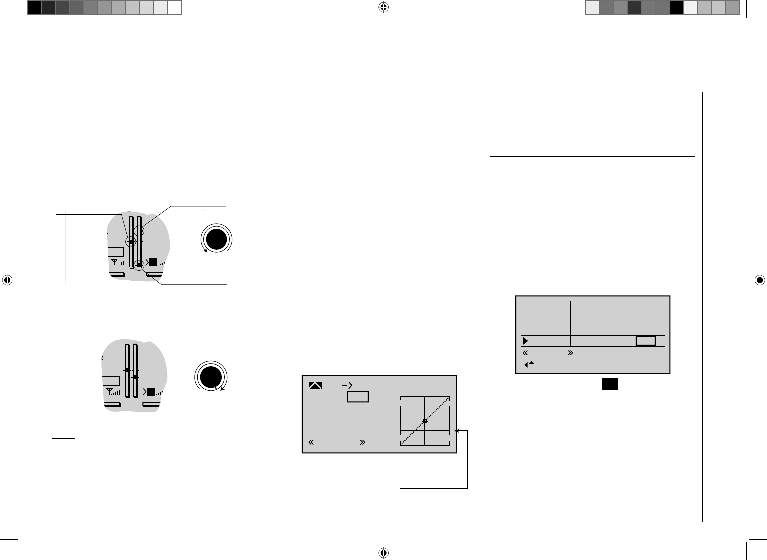
106 Detail program description - Control adjust
marker is located at the end-point (see the partial
display screenshot shown below), then you can simply
click once to restore the original idle confi guration (see
also page 54).
This switch-off trim functions as an idle trim only in the
left half of the throttle limit rotary control's path. That
is: only within this range is the marker line set and also
stored.
GRAUBELE
#01
3:33h
stop
flt
K78
0:00
0:00
RX0.0V
5.2V
Last idle position
2.4
M
motor OFF position
CTRL 6
Throttle limit control
Current trim position
Trim at
For this reason, the marker is hidden and may even be
erased while the throttle limit rotary control points to the
right of its center position:
GRAUBELE
#01
3:33h
Stop
Flt
K78
0:00
0:00
RX0.0V
5.2V
M2.4CTRL 6
Throttle limit control
Notes:
Since this trim function only takes effect in the •
"Motor OFF" direction, the screen image shown
above changes appropriately if you alter the control
direction for the pitch minimum position of the C1
stick from "back" (as shown in the above image) to
"forward" in the "min. pitch" line on the menu "Base
setup model". The effects as shown also swap to
the other side if you swap pitch right (as shown in the
above screen images) to pitch left in the "Stick mode"
line on the "Base setup model" menu (see page 74).
You can use the •"Servo display" menu to observe
the infl uence of the throttle limit slider. This menu
can be accessed from almost any other menu by
simultaneously pressing the ef keys on the left
touch pad. Bear in mind that servo output 6 controls
the throttle servo on the mc-32 HoTT!
A servo connected to output 12 can be used •
independently of this for other purposes by means of
mixers, provided that you separate the servo from the
transmitter control at function input 12 on the "MIX-
only channel" menu; see page 193.
The throttle restriction set by the throttle limiter •
is shown as a horizontal bar in the throttle curve
diagram on the second display page of the "Channel
1¼ Throttle" option on the "Helicopter mixers"
menu (see page 168). The output signal for the
throttle servo cannot be higher than the level set by
the horizontal bar:
Input
Output
Point 2
0%
0%
0%
C1
Normal
Thr
Curve off
Throttle limiter
position
The above diagram shows precisely this scenario: in
the above example, the throttle limit control is set to
-60% and thus restricts the movement of the throttle
servo to -60% of full travel.
Time delay for the throttle limiter
To safely avoid the carburetor opening too rapidly, you
should assign throttle limiter input 12 a time delay that
takes effect only in the direction of full throttle. This
applies especially if you are controlling the throttle limiter
using a switch and not the default CTRL 6 proportional
rotary control.
To set a delay time, proceed as follows: turn the throttle
limit control as far to the right as it will go or move the
relevant switch to the full-throttle position; then use the
arrow keys on the left or right touch pad to select the
"–time+" column:
– time +
0.0
0.0
0.0
0.0
0.0
0.0
0.0
0.0
Normal
Input 9
Input10
Input
Th.L.12
11
After briefl y tapping the center SET key on the right
touch pad, you can then use the arrow keys on the left
or right touch pad to select your desired time delay, e. g.
5 seconds:
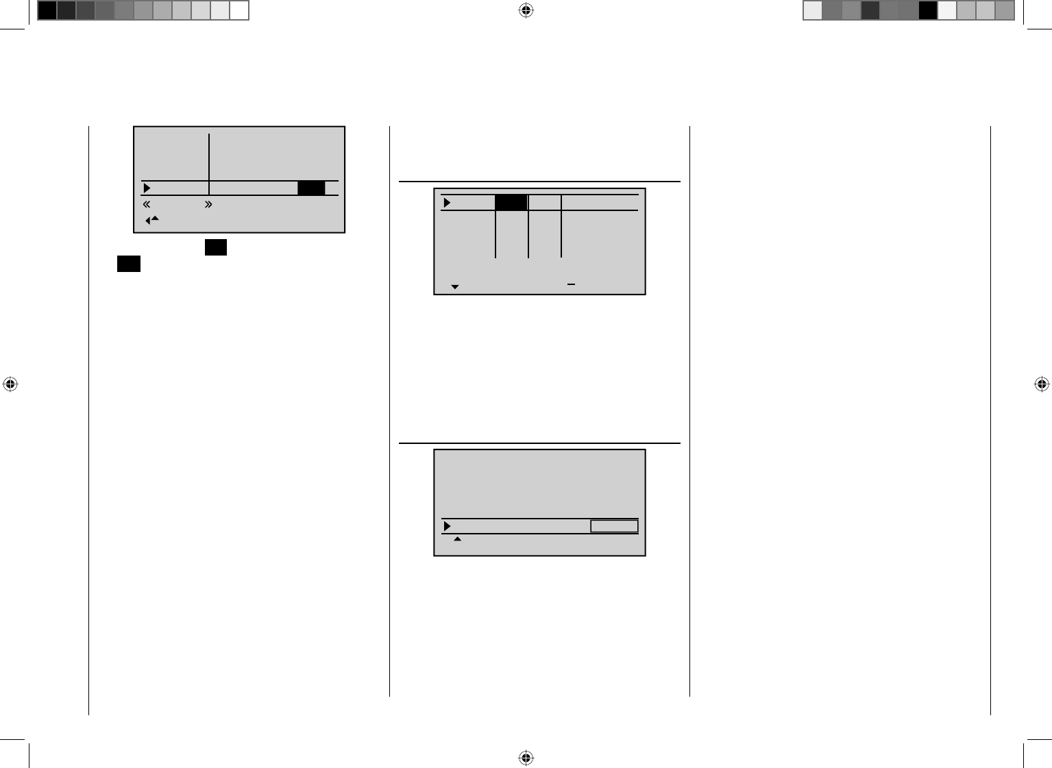
107
Detail program description - Control adjust
– time +
0.0
0.0
0.0
0.0
0.0
0.0
0.0
Normal
Input 9
Input10
Input
Th.L.12
11
5.0
Briefl y tap the center SET key on the right touch pad or
the ESC key on the left touch pad to complete the setup
procedure.
As already explained on page 94, selecting "Thr AR" in
the "Thr." line on the menu …
"Stick mode" (page 94)
Thr.
Roll
Nick
Tr +
time
4
4
4
0.0s
0.0s
0.0s
40.0s
Tail
0.0s
0.0s
0.0s
0.0s
GL
GL
GL
St
TA
… makes the digital trim of the throttle/collective pitch
stick active only in the "Autorot" fl ight phase. As a result,
in "normal" fl ight phases, the C1 trim lever can be used
neither to control the motor's idling nor to stop the motor.
To ensure you still retain suffi cient adjustment options,
we recommend using "Expo throttle limit" here.
This sub-menu for this is found on the menu …
"Helicopter type" (page 86)
Expo thro lim. 0%
SEL
Linear. swashpl. no
Rotor direct right
HELI TYPE
Pitch min. back
… and the exponential curve characteristic it confi gures
can adjust the control characteristics of the throttle limit
control so that the latter provides suffi ciently fi ne control
of the idle setting and can also stop the motor.
In this case you should turn the throttle limiter fully to
the left – unlike the previously described setting on the
"Control adjust" menu – and adjust the "–" side of the
"–travel+" column in the "Th.L.12" line so the throttle
Throttle limit in conjunction with "Thr AR" on the "Stick mode" menu
limiter fully closes the carburetor, i.e. the motor is safely
switched off at this control position.
Following this, move the throttle limit control to its center
point and change the % value of the "Expo thro lim." line
in the "Helicopter type" menu (see page 86) until the
carburetor is in a position suitable for starting the motor.
Now start the motor, and adjust the value if necessary
until the motor idles reliably in this throttle limit control
position.
For the plus side of the "–travel+" column, increase the
value to +125% as described before, so that the full-
throttle position of the throttle servo is also released
reliably by the throttle limiter.
Finally, set an asymmetrical time delay of, say,
4.0 seconds, so that the motor also picks up speed
gradually even if you move the proportional rotary
control too quickly to the right. Select the time preset
to correlate to how far the carburetor opens up at the
minimum collective pitch position. The value you set will
need fi ne-tuning by practical testing.
108 Detail program description - Control adjust
Dual Rate / Expo
Confi gurable control characteristics for aileron, elevator and rudder
Using the arrow keys on the left or right touch pad, page
to the menu option "Dual Rate / Expo" in the multi-
function list:
Servo adjustment
Stick mode.
Channel 1 curve
Switch display
Control adjust.
Dual Rate / Expo
Tap the center SET key on the right touch pad to open
the menu shown below:
100%
100%
100%
Ail
Ele
Rud
DUAL
–––
–––
–––
SEL
The Dual Rate / Expo function permits switching or
controlling of control travels and characteristics for
aileron (Ail), elevator (Ele) and rudder (Rud) (control
functions 2 … 4); it is switch-driven and fl ight-phase
independent.
The "Channel 1 curve" menu (see p. 116f.) can be
used to set an individual curve characteristic for control
function 1 (throttle/brake), featuring up to 6 separately
programmable points.
As with transmitter control travel adjustment on the
"Control adjust" menu, Dual Rate affects the relevant
control function directly, whether it controls a single
servo or multiple servos – via mixer and coupling
functions of arbitrary complexity.
The control travels for each switch position can be set to
between 0% and 125% of the normal full travel.
Expo, on the other hand, enables fi ner-grained control
of the model for values larger than 0% around the
center position of the primary control function (aileron,
elevator and rudder), without forfeiting full movement
at the end-points of joystick travel. For values less than
0%, the reverse is true: control increases around the
neutral position and diminishes towards the end-points.
The degree of "progression" can therefore be set within
a total range of -100% to +100%, where 0% equates to
the normal, linear control characteristics.
Rotary-output servos, now generally commonplace,
offer another application. This is because the actual
control surface movement is not linear: as the rotational
angle of the output disc or lever increases, the control
surface rate of travel over the control linkage continually
decreases – depending on the position of the linkage
point on the output disc. You can counteract this effect
with Expo values greater than 0%, so that angular travel
increases over proportionately as stick travel increases.
The Expo setting also affects the relevant control
function directly, whether this controls a single servo or
multiple servos – via any number of mixer and coupling
functions.
For both Dual Rate and Expo functions, switch
assignment can be set up in any way desired, which
therefore permits the triggering of multiple functions
using one and the same switch. This, in turn, offers the
opportunity to link the triggering of Dual Rate and Expo
functions to a single switch: this offers many advantages
– particularly for very high-speed models.
The graphic screen displays the curve characteristics
directly. Once you select a menu line, the dotted vertical
line follows the movement of the respective joystick, so
you can clearly see the dependency of the curve value
on the transmitter control.
Flight phase-dependent Dual Rate and Expo
settings
If you have set up fl ight phases in the "Phase settings"
and "Phase assignment" menus and assigned each of
these a name – e. g. "normal" – the name in question
is displayed at the bottom left. In this scenario, you can
operate the corresponding switch to switch between
fl ight phases.
Basic procedure
Switch to the desired fl ight phase and then use 1.
the arrow keys cd on the left or right touch pad
to select your chosen menu line, i.e. "Ail", "Ele" or
"Rud".
Using the arrow keys 2. ef on the left or right touch
pad, select the right column or the as-yet invisible
column for Expo values (see page 27).
Tap the center 3. SET key on the right touch pad. The
corresponding input fi
eld is shown highlighted.
Use 4. the arrow keys on the right touch pad to set your
chosen value.
Tap the center 5. SET key on the right touch pad to
complete data entry.
If you tap the 6. cd or ef keys on the right touch
pad at the same time (CLEAR), this will reset any
settings made back to their respective default values.
Dual Rate function
If you want to be able to switch between two variants,
assign a switch in the column marked with the switch
icon at the lower edge of the display, as described in
the section "Assigning transmitter controls, switches and
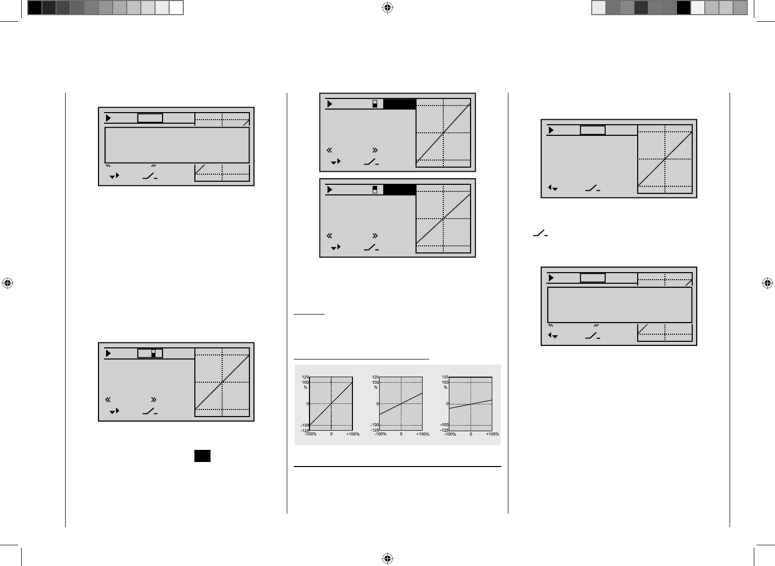
109
Detail program description - Control adjust
100%
100%
DUAL
3
–––
–––
SEL
normal
111%Ail
Ele
Rud
100%
100%
DUAL
3
–––
–––
SEL
normal
88%
Ail
Ele
Rud
If you tap the cd or ef keys on the right touch
pad at the same time (CLEAR), this will reset a value
changed in the highlighted fi eld back to 100%.
Caution:
For safety reasons, you should not set Dual Rate values
lower than 20%.
Some examples of Dual Rate values:
Servo travel
Servo travel
Servo travel
Stick deflection Stick deflection Stick deflection
Dual Rate = 100% Dual Rate = 50% Dual Rate = 20%
Exponential function
If you want to be able to switch between two variants,
use the f key on the left or right touch pad to move
to the right beyond the Dual Rate value column, until
control switches" (page 52):
100%
100%
100%
Ail
HR
SR
DUAL
–––
–––
–––
SEL
normal
Move desired switch
to ON position
(ext. switch: SET )
The switch so assigned appears on the display, together
with a switch icon that indicates the switch's switching
direction.
With "G" switches from the "expanded switches" menu,
the joystick or another transmitter control acts as the
switch itself. However, this kind of control switch must
be defi ned appropriately beforehand on the "Control
switches" menu (see page 123).
Whichever switch has been assigned …
the respective switch appears on the display together
with a switch icon that indicates the switch's respective
direction when moved.
100%
100%
100%
Ail
Ele
Rud
DUAL
3
–––
–––
SEL
normal
If you select the right-hand column at the lower edge
of the display marked with SEL and activate the value
fi eld by briefl y tapping the center SET key on the right
touch pad, you can use the arrow keys on the left or
right touch pad to alter the Dual Rate value shown in the
highlighted fi eld separately for each of the two switch
positions:
the word "DUAL" (shown roughly in the middle of the
display) changes to "EXPO":
0%
0%
0%
EXPO
–––
–––
–––
SEL
Ail
Ele
Rud
If you want to be able to switch between two variants,
assign a switch in the column marked with the switch
icon at the lower edge of the display, as described in
the section "Assigning transmitter controls, switches and
control switches" (page 52):
0%
100%
100%
Ail
Ele
SR
DUAL
–––
–––
–––
SEL
normal
Move desired switch
to ON position
(ext. switch: SET )
The switch so assigned appears on the display, together
with a switch icon that indicates the switch's respective
switching direction.
With "G" switches from the "expanded switches" menu,
the joystick or another transmitter control acts as the
switch itself. However, the control switch in question
must be defi ned appropriately beforehand on the
"Control switches" menu (see page 123).
Whichever switch has been assigned …
the respective switch appears on the display together
with a switch icon that indicates the switch's respective
direction when moved.

110 Detail program description - Control adjust
0%
0%
0%
Ail
Ele
Rud
EXPO
3
–––
–––
SEL
normal
If you select the right-hand column at the lower edge
of the display marked with SEL and activate the value
fi eld by briefl y tapping the center SET key on the right
touch pad, you can use the arrow keys on the left or
right touch pad to alter the Expo value shown in the
highlighted fi eld separately for each of the two switch
positions:
Now, for example, you have the opportunity to fl y with
a linear curve characteristic with the switch in one
direction, and to pre-set a value other than 0% in the
other switching direction:
33%
0%
0%
Ail
Ele
Rud
EXPO
3
–––
–––
SEL
normal
If you tap the cd or ef keys on the right touch
pad at the same time (CLEAR), this will reset a value
changed in the highlighted fi eld back to 0%.
Some examples of Expo values:
Servo travel
Servo travel
Servo travel
Stick deflection Stick deflection Stick deflection
Expo = +100% Expo = +50% Expo = –100%
In each of these examples, the Dual Rate value equals
100%.
Combining Dual Rate and Expo
If you have entered values for both the Dual Rate
and the Expo function, the effect from on function
is superimposed on the other, as shown in these
examples:
Servo travel
Servo travel
Servo travel
Stick deflection Stick deflection Stick deflection
Expo = +100%, DR = 125% Expo = +100%, DR = 50% Expo = –100%, DR = 50%
Asymmetric setting of Dual Rate and Expo
To make an asymmetric setting, i. e. a Dual Rate or Expo
setting dependent on the direction of the respective
joystick, fi rst access the "Control switches" menu and
assign one of the C1 … C4 control switches – "C3",
for example – your chosen transmitter control, e. g.
control 3 for the elevator function. Leave the switching
point at the joystick's neutral position (0%), however.
Now return to the "Dual Rate / Expo" menu and select
the corresponding control function ("Elevator" in this
example).
Activate "Switch assignment" and tap the center
SET key briefl y on the right touch pad to switch to
the expanded switches. Here, use the arrow keys to
continue switching to the control switch "G3" that you
defi ned previously:
100%
100%
100%
Ail
HR
SR
DUAL
–––
–––
–––
SEL
normal
Control / fix sw
C1 C2 C3 C4 FX
FXi C1i C2i C3i C4i
Tap the center SET key on the right touch pad to confi rm
the assignment of this switch:
100%
100%
100%
Ail
Ele
Rud
DUAL
–––
C3
–––
SEL
normal
Now use one of the arrow keys to move to the right
column and then move the elevator joystick to the
appropriate end-point in order to enter a separate Dual
Rate value for each direction, e. g. for "Up elevator" …
100%
100%
Ail
Ele
Rud
DUAL
–––
C3
–––
SEL
normal
77%
… and "Down elevator":
111
Detail program description - Control adjust
100%
100%
Ail
Ele
Rud
DUAL
–––
C3
–––
SEL
normal
111%
Set the Expo values in the same way.
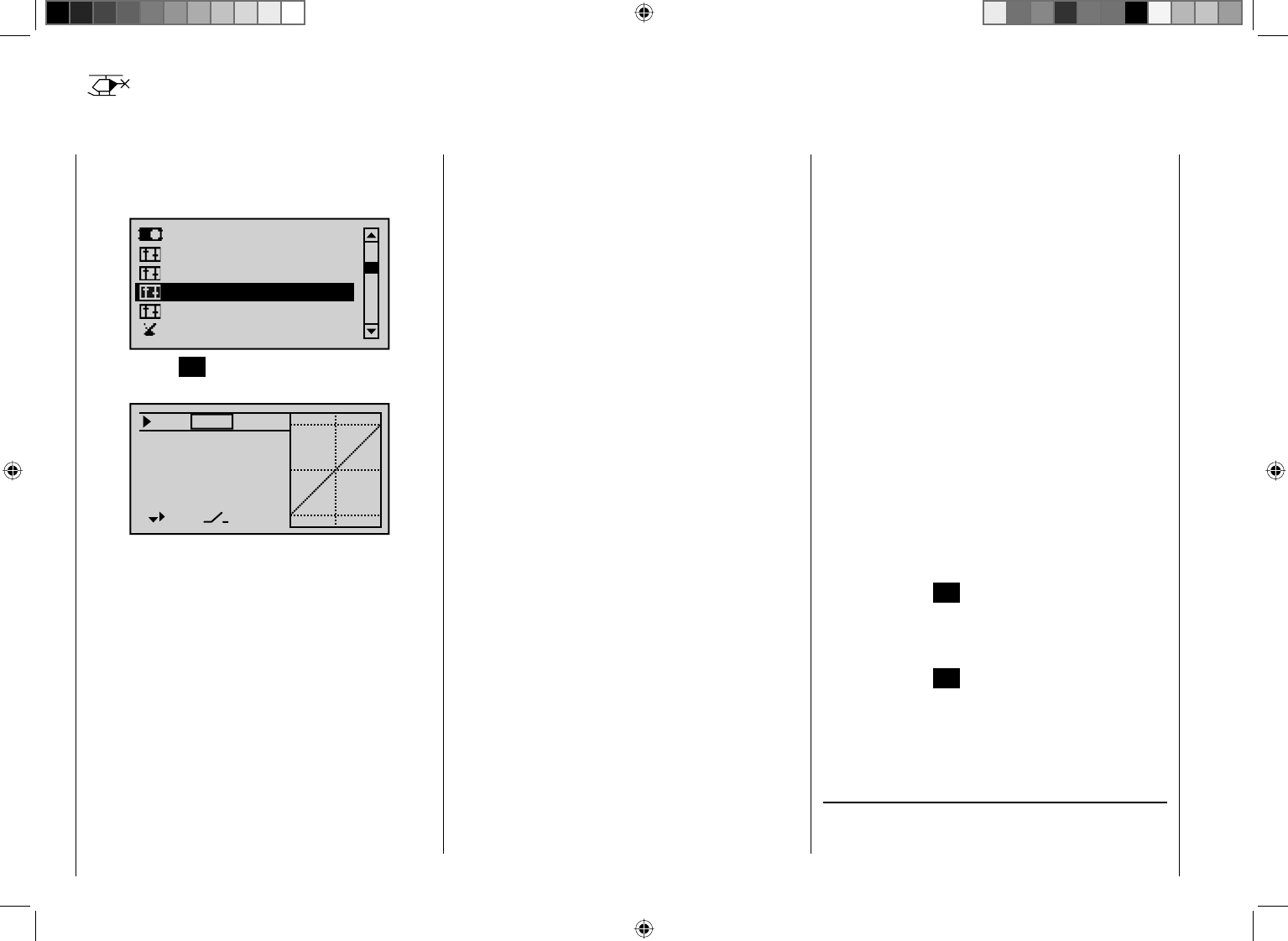
112 Detail program description - Control adjust
Dual Rate / Expo
Confi gurable control characteristics for roll, pitch-axis, tail rotor
Using the arrow keys on the left or right touch pad, page
to the menu option "Dual Rate / Expo" in the multi-
function list:
Servo adjustment
Stick mode.
Channel 1 curve
Switch display
Control adjust.
Dual Rate / Expo
Tap the center SET key on the right touch pad to open
the menu shown below:
100%
100%
100%
Roll
Nick
Tail
DUAL
–––
–––
–––
SEL
The Dual Rate / Expo function permits switching or
controlling of control travels and characteristics for the
control functions roll, pitch-axis, tail rotor, i. e. control
functions 2 … 4; it is switch-driven and fl ight-phase
independent.
An individual curve characteristic for control function
1 (motor/collective pitch), featuring up to 6 separately
programmable points, can be set either on the "Channel
1 curve" menu (page 119) or separately for throttle and
collective pitch on the "Helicopter mixers" menu (see
p. 165f.).
As with transmitter control travel adjustment on the
"Control adjust" menu, Dual Rate affects the relevant
control function directly, whether it controls a single
servo or multiple servos – via mixer and coupling
functions of arbitrary complexity.
The control travels for each switch position can be set to
between 0% and 125% of the normal full travel.
Expo, on the other hand, enables fi ner-grained control
of the model for values larger than 0% around the center
position of the primary control function (roll, pitch-axis,
tail rotor), without forfeiting full movement at the end-
points of joystick travel. For values less than 0%, the
reverse is true: control increases around the neutral
position and diminishes towards the end-points. The
degree of "progression" can therefore be set within a
total range of -100% to +100%, where 0% equates to
the normal, linear control characteristics.
Rotary-output servos, now generally commonplace,
offer another application. This is because the actual
control surface movement is not linear: as the rotational
angle of the output disc or lever increases, the control
surface rate of travel over the control linkage continually
decreases – depending on the position of the linkage
point on the output disc. You can counteract this effect
with Expo values greater than 0%, so that angular travel
increases overproportionately as stick travel increases.
The Expo setting also affects the relevant control
function directly, whether this controls a single servo or
multiple servos – via any number of mixer and coupling
functions.
For both Dual Rate and Expo functions, switch
assignment can be set up in any way desired, which
therefore permits the triggering of multiple functions
using one and the same switch. This, in turn, offers the
opportunity to link the triggering of Dual Rate and Expo
functions to a single switch: this offers many advantages
– particularly for very high-speed models.
The graphic screen displays the curve characteristics
directly. Once you select a menu line, the dotted vertical
line follows the movement of the respective joystick, so
you can clearly see the dependency of the curve value
on the transmitter control.
Flight phase-dependent Dual Rate and Expo
settings
If you have set up fl ight phases in the "Phase settings"
and "Phase assignment" menus and assigned each of
these a name – e. g. "normal" – the name in question
is displayed at the bottom left. In this scenario, you can
operate the corresponding switch to switch between
fl ight phases.
Basic procedure
Switch to the desired fl ight phase and then use the 1.
arrow keys cd on the left or right touch pad to
select your chosen menu line, i.e. "Roll", "Nick" or
"Tail".
Using the arrow keys 2. ef on the left or right touch
pad, select the right column or the as-yet invisible
column for Expo values (see page 27 ).
Tap the center 3. SET key on the right touch pad. The
corresponding input fi
eld is shown highlighted.
Use 4. the arrow keys on the right touch pad to set your
chosen value.
Tap the center 5. SET key on the right touch pad to
complete data entry.
If you tap the 6. cd or ef keys on the right touch
pad at the same time (CLEAR), this will reset any
settings made back to their respective default values.
Dual Rate function
If you want to be able to switch between two variants,
assign a switch in the column marked with the switch
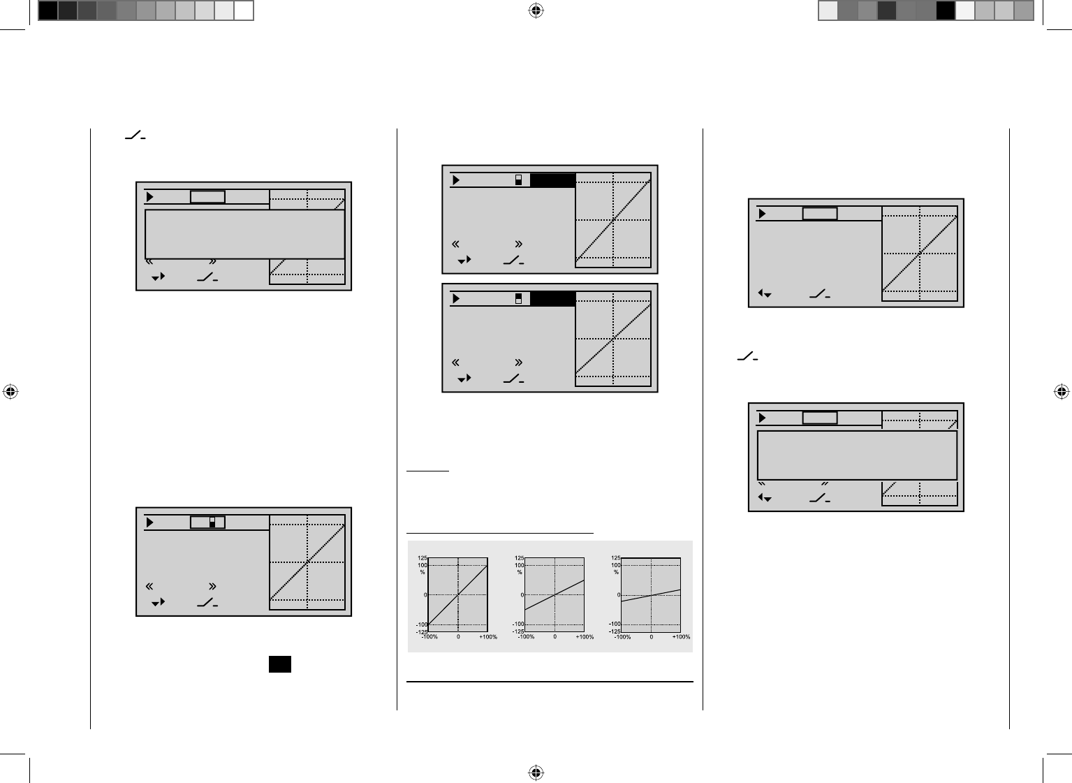
113
Detail program description - Control adjust
use the f key on the left or right touch pad to move
to the right beyond the Dual Rate value column, until
the word "DUAL" (shown roughly in the middle of the
display) changes to "EXPO":
0%
0%
0%
EXPO
–––
–––
–––
SEL
Roll
Nick
Tail
If you want to be able to switch between two variants,
assign a switch in the column marked with the switch
icon at the lower edge of the display, as described
in the section "Assigning transmitter controls, switches
and control switches" (page 52):
0%
100%
100%
Roll
Nick
SR
DUAL
–––
–––
–––
SEL
normal
Move desired switch
to ON position
(ext. switch: SET )
The switch so assigned appears on the display, together
with a switch icon that indicates the switch's respective
switching direction.
With "G" switches from the "expanded switches" menu,
the joystick or another transmitter control acts as the
switch itself. However, the control switch in question
must be defi ned appropriately beforehand on the
"Control switches " menu (see page 123).
Whichever switch has been assigned … the respective
switch appears on the display together with a switch icon
that indicates the switch's respective direction when moved.
icon at the lower edge of the display, as described
in the section "Assigning transmitter controls, switches
and control switches" (page 52 ):
100%
100%
100%
Roll
Nick
SR
DUAL
–––
–––
–––
SEL
normal
Move desired switch
to ON position
(ext. switch: SET )
The switch so assigned appears on the display, together
with a switch icon that indicates the switch's switching
direction.
With "G" switches from the "expanded switches" menu,
the joystick or another transmitter control acts as the
switch itself. However, this kind of control switch must
be defi ned appropriately beforehand on the "Control
switches" menu (see page 123).
Whichever switch has been assigned …
the respective switch appears on the display together
with a switch icon that indicates the switch's respective
direction when moved.
100%
100%
100%
Roll
Nick
Tail
DUAL
3
–––
–––
SEL
normal
If you select the right-hand column at the lower edge
of the display marked with SEL and activate the value
fi eld by briefl y tapping the center SET key on the right
touch pad, you can use the arrow keys on the left or
right touch pad to alter the Dual Rate value shown in the
highlighted fi eld separately for each of the two switch
positions:
100%
100%
DUAL
3
–––
–––
SEL
normal
111%
Roll
Nick
Tail
100%
100%
DUAL
3
–––
–––
SEL
normal
88%
Roll
Nick
Tail
If you tap the cd or ef keys on the right touch
pad (CLEAR) at the same time, this will reset a value
changed in the highlighted fi eld back to 100%.
Caution:
For safety reasons, you should not set Dual Rate values
lower than 20%.
Some examples of Dual Rate values:
Servo travel
Servo travel
Servo travel
Stick deflection Stick deflection Stick deflection
Dual Rate = 100% Dual Rate = 50% Dual Rate = 20%
Exponential function
If you want to be able to switch between two variants,
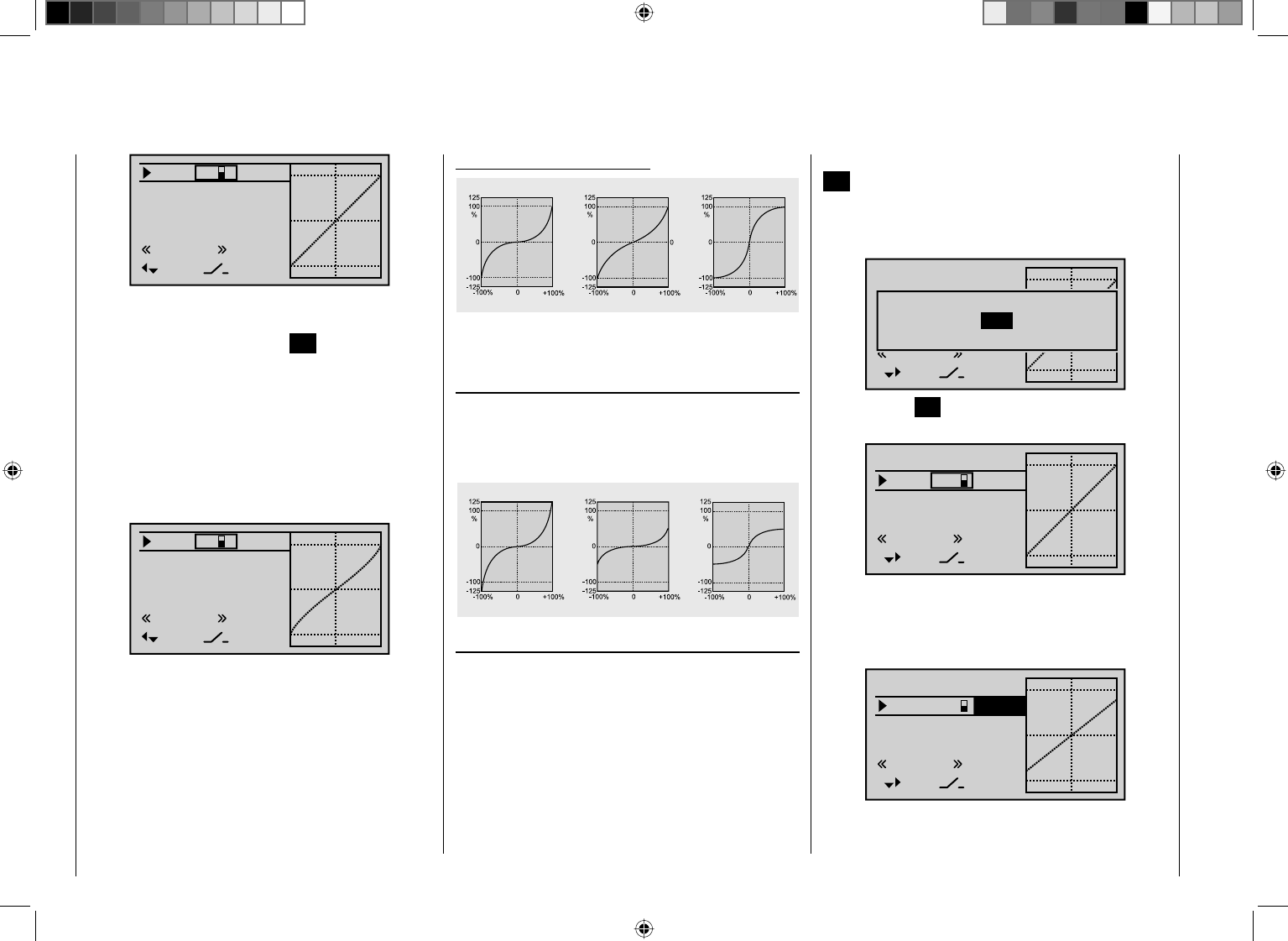
114 Detail program description - Control adjust
0%
0%
0%
EXPO
3
–––
–––
SEL
normal
Roll
Nick
Tail
If you select the right-handcolumn at the lower edge
of the display marked with SEL and activate the value
fi eld by briefl y tapping the center SET key on the right
touch pad, you can use the arrow keys on the left or
right touch pad to alter the Expo value shown in the
highlighted fi eld separately for each of the two switch
positions:
Now, for example, you have the opportunity to fl y with
a linear curve characteristic with the switch in one
direction, and to pre-set a value other than 0% in the
other switching direction:
33%
0%
0%
EXPO
3
–––
–––
SEL
normal
Roll
Nick
Tail
If you tap the cd or ef keys on the right touch
pad (CLEAR) at the same time, this will reset a value
changed in the highlighted fi eld back to 0%.
Some examples of Expo values:
Servo travel
Servo travel
Servo travel
Stick deflection Stick deflection Stick deflection
Expo = +100% Expo = +50% Expo = –100%
In each of these examples, the Dual Rate value equals
100%.
Combining Dual Rate and Expo
If you have entered values for both the Dual Rate
and the Expo function, the effect from on function
is superimposed on the other, as shown in these
examples:
Servo travel
Servo travel
Servo travel
Stick deflection Stick deflection Stick deflection
Expo = +100%, DR = 125% Expo = +100%, DR = 50% Expo = –100%, DR = 50%
Asymmetric setting of Dual Rate and Expo
To make an asymmetric setting, i. e. a Dual Rate or Expo
setting dependent on the direction of the respective
joystick, fi rst access the "Control switches" menu and
assign one of the C1 … C4 control switches – "C3", for
example – your chosen transmitter control, e. g. control
3 for the pitch-axis function. Leave the switching point
at the joystick's neutral position (0%), however. Now
return to the "Dual Rate / Expo" menu and select the
corresponding control function ("Nick" in this example).
Activate "Switch assignment" and tap the center
SET key briefl y on the right touch pad to switch to
the expanded switches. Here, use the arrow keys to
continue switching to the control switch "G3" that you
defi ned previously:
100%
100%
100%
Roll
HR
SR
DUAL
–––
–––
–––
SEL
normal
Control / fix sw
C1 C2 C3 C4 FX
FXi C1i C2i C3i C4i
Tap the center SET key on the right touch pad to confi rm
the assignment of this switch:
100%
100%
100%
DUAL
–––
C3
–––
SEL
normal
Roll
Nick
Tail
Now use one of the arrow keys to move to the right
column and then move the pitch-axis joystick to the
appropriate end-point in order to enter a separate Dual
Rate value for each direction, e. g. for "Pitch-axis up" …
100%
100%
DUAL
–––
C3
–––
SEL
normal
Roll
Nick
Tail
77%
and "Pitch-axis down":

115
Detail program description - Control adjust
100%
100%
DUAL
–––
C3
–––
SEL
normal
Roll
Nick
Tail
111%
Set the Expo values in the same way.
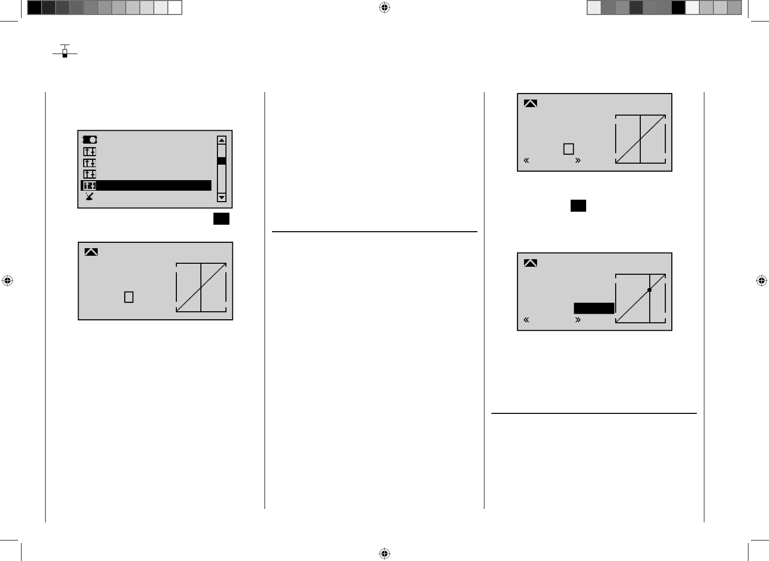
116 Detail program description - Control adjust
Channel 1 curve
Control characteristics for throttle/spoiler joystick
Using the arrow keys on the left or right touch pad, page
to the menu option "Channel 1 curve" in the multi-
function list:
Servo adjustment
Stick mode
Switch display
Control adjust
Dual Rate / Expo
Channel 1 curve
Open this menu item by pressing the center SET button
in the right touch pad.
Input
Output
Point ?
0%
0%
0%
C1
normal
Curve
Curve off
Since the carburetor response or the effect of the
airbrakes or spoilers is often non-linear, you can make
compensatory adjustments to these in this menu.
The menu therefore enables you to change the
control characteristics of the throttle / airbrake joystick,
regardless of whether this control function affects the
servo connected to control channel 1 directly or affects
multiple servos via various mixers.
If you have used the "Phase settings" and "Phase
assignment" menus (see pages 128 and 134) to
specify fl ight phases, this option can be adjusted per
fl ight phase. The fl ight phase name – e. g. "normal" – is
always shown at the bottom left of the screen.
The control curve can be defi ned by up to 6 points
(termed "reference points" below) placed anywhere
along the path of joystick travel. While the on-screen
graph considerably simplifi es the process of setting and
adjusting the reference points, we recommend that you
set fewer reference points to begin with.
In the basic software set-up, 2 reference points –
namely the end-points at the bottom end of joystick
travel ("L", low = -100% travel) and the top end of
joystick travel ("H", high = +100% travel) – defi ne a
linear characteristic curve.
First, switch to your chosen fl ight phase, if necessary.
Setting reference points
By moving the transmitter control (throttle/airbrake
joystick), you can reposition the vertical line in the graph
between the two end-points "L" and "H". The current
joystick position is also displayed in numerical form on
the "Input" line (-100% to +100%). The point at which
this line crosses the curve is termed the "Output", and
can be varied at the reference points within the range
-125% to +125%. The control signal altered in this
way will then affect all subsequent mixer and coupling
functions.
In the example above, the joystick is at 0% of control
travel and also generates an output signal of 0%, since
the characteristic curve is linear.
Up to 4 additional reference points can be set between
the two end-points "L" and "H", although the distance
between neighboring reference points must not be less
than approx. 25%.
If necessary, use the left or right arrow key d to drag
the marker frame downwards, until it is at the "Point"
line:
?
0%
0%
0%
Normal
off
Input
Output
Point
C1 Curve
Curve
Move the joystick. If a question mark can be seen in
the frame, then you can set the next reference point
by tapping the center SET key on the right touch pad.
Simultaneously, the "?" is replaced by a number and the
value fi eld to the right of the reference point number is
highlighted:
1
+50%
+50%
+50%
Normal
off
Input
Output
Point
C1 Curve
Curve
The order in which you generate the (maximum) 4
reference points between the end-points "L" and "H" is
irrelevant, since the reference points are continuously
renumbered automatically from left to right as they are
entered.
Deleting reference points
To delete one of the reference points (1 to max. 4), use
the joystick to move the vertical line into the vicinity of
the reference point in question. As soon as the reference
point number and its associated value is shown on
the "Point" line (see screen image above), you can
activate the value fi eld on the "Point" line to highlight
it by simultaneously tapping the cd or ef keys on
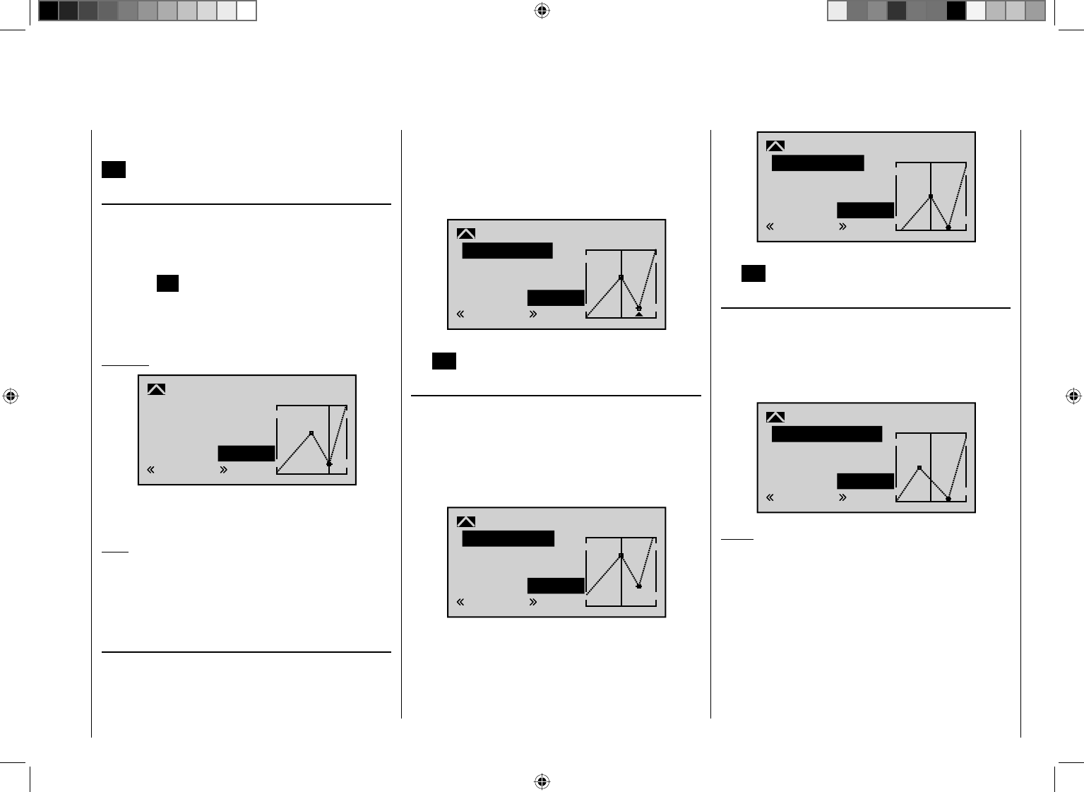
117
Detail program description - Control adjust
the right touch pad (CLEAR) and then delete the value.
Complete the operation by briefl y tapping the center key
ESC on the left touch pad.
Changing reference point values
Move the joystick into the range of the reference point
that is to be changed: "L" (low), 1 … 4 or "H" (high).
The number and current curve value of this point are
displayed. Activate the value fi eld by briefl y tapping
the center SET key on the right touch pad. The point
value fi eld is now highlighted and can be set within the
range -125% to +125%, and without infl uencing the
neighboring reference points.
Example:
2
+50%
–75%
–75%
Normal
off
Input
Output
Point
C1 Curve
Curve
In this sample screen image, reference point "2" has
been set to -75%.
Note:
If the joystick does not coincide with the exact reference
point, please note that the percentage value on the
"Output" line always relates to the current joystick
position.
Trim point function
Alternatively, assuming the value fi
eld is active, i. e.
highlighted, you can use the up or down arrow keys
ef on the left touch pad to jump to reference points
already set. In this case, a triangle is shown on the
graph to indicate each point jumped to. The arrow keys
on the right touch pad can then be used to change the
reference point jumped to as described above, entirely
independently of the control position:
2
+50%
–75%
–75%
Trim point
Normal
Input
Output
Point
C1 Curve
Exit from trim point function setting by tapping the center
key ESC on the left touch pad.
Trim offset function
Assuming the value fi eld is active, i. e. highlighted, you
can not only use the up or down arrow keys ef on the
left touch pad to jump to reference points already set
and change their values, but you can also use the cd
keys on the left touch pad to vertically reposition an
existing curve within the range ±25%:
1
0%
+50%
+50%
Trim offset
Normal
Input
Output
Point
C1 Curve
1
0%
0%
0%
Trim offset
Normal
Input
Output
Point
C1 Curve
You can also exit from this function by tapping the center
key ESC on the left touch pad.
Trim x-axis function
This function is activated by tapping the left (e) or right
(f) arrow key on the right touch pad with an active
(i. e. highlighted) value fi eld. You can then use the arrow
keys on the right touch pad to reposition the active point
horizontally or vertically as you wish.
?
0%
–33%
0%
Trim X-axis
Normal
Input
Output
Point
C1 Curve
Notes:
If you reposition the point horizontally further away •
from the current control position than approx. ±25%,
a "?" sign re-appears in the line. This question mark
does not refer to the repositioned point, however:
instead, it signifi es that a further point can be set at
the current control position.
Please note that the percentage value on the •
"Output" line always relates to the current joystick
position and not to the position of the point.
118 Detail program description - Control adjust
Smoothing the Channel 1 curve
In the example below, sample reference points have
been set:
Reference point 1 to 0%
Reference point 2 to +25%
Reference point 3 to -75%
as described in the last section.
1
–50%
0%
0%
Normal
off
Input
Output
Point
C1 Curve
Curve
This "jagged" curve profi le can be smoothed
automatically simply by pressing a button.
First – assuming a situation is confi gured as presented
above – tap the center ESC button on the left touch pad
to deactivate the value fi eld. Then use the arrow keys on
the left or right touch pad to move the marker frame in
an upwards direction to the "Curve" line. Now briefl y tap
the center SET key on the right touch pad to activate the
value fi eld on the "Curve" line:
1
–50%
0%
0%
off
Normal
Input
Output
Point
C1 Curve
Curve
Use the arrow keys on the right touch pad to set the
curve value from "off" to "on" and complete this setup
procedure by briefl y tapping the center SET the center
SET key on the right touch pad or the center ESC key
on the left touch pad:
1
–50%
0%
0%
on
Normal
Input
Output
Point
C1 Curve
Curve
Note:
The curves shown here are for demonstration purposes
only and are not at all representative of real throttle/
airbrake curves. For real-world application examples,
see the programming examples from page 242 onwards.
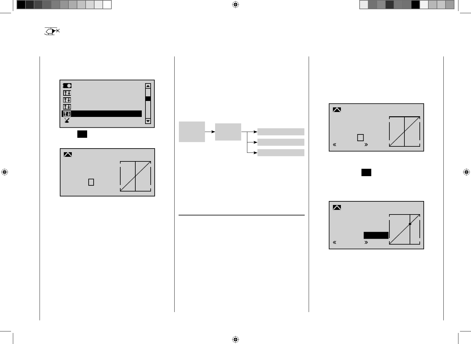
119
Detail program description - Control adjust
Channel 1 curve
Control characteristics for throttle/collective pitch stick
Using the arrow keys on the left or right touch pad, page
to the menu option "Channel 1 curve" in the multi-
function list:
Servo adjustment
Stick mode
Switch display
Control adjust
Dual Rate / Expo
Channel 1 curve
Tap the center SET key on the right touch pad to open
the menu shown below:
Input
Output
Point ?
0%
0%
0%
C1
normal
Curve
Curve off
Since the carburetor response or the effect of collective
pitch is often non-linear, you can make compensatory
adjustments to these in this menu.
The menu therefore enables you to change the control
characteristics of the motor/collective pitch stick,
regardless of whether this control function affects the
servo connected to control channel 1 directly or affects
multiple servos via various mixers.
If you have used the "Phase settings" and "Phase
assignment" menus (see pages 128 and 134 ) to
specify fl ight phases, this option can be adjusted per
fl ight phase. The fl ight phase name – e. g. "normal" – is
always shown at the bottom left of the screen.
The control curve can be defi ned by up to 6 points
(termed "reference points" below) placed anywhere
along the path of joystick travel. While the on-screen
graph considerably simplifi es the process of setting and
adjusting the reference points, we recommend that you
set fewer reference points to begin with.
Please note that the curve characteristic you set
here acts as the input signal for specifi c mixers in the
"Helicopter mixers" menu (see page 164):
"Helicopter mixers"
Collec-
tive pitch
stick
Collective pitch
C1 ¼ Thr
C1 ¼ Tail rotor
C1
curve
In the basic software set-up, 2 reference points –
namely the end-points at the bottom end of joystick
travel ("L", low = -100% travel) and the top end of
joystick travel ("H", high = +100% travel) – defi ne a
linear characteristic curve.
First, switch to your chosen fl ight phase, if necessary.
Setting reference points
By moving the transmitter control (motor/collective pitch
stick), you can reposition the vertical line in the graph
between the two end-points "L" and "H". The current
joystick position is also displayed in numerical form on
the "Input" line (-100% to +100%). The point at which
this line crosses the curve is termed the "Output", and
can be varied at the reference points within the range
-125% to +125%. The control signal altered in this
way will then affect all subsequent mixer and coupling
functions.
In the example above, the joystick is at 0% of control
travel and also generates an output signal of 0%, since
the characteristic curve is linear.
Up to 4 additional reference points can be set between
the two end-points "L" and "H", although the distance
between neighboring reference points must not be less
than approx. 25%.
If necessary, use the left or right arrow key d to drag the
marker frame downwards, until it is at the "Point" line:
?
0%
0%
0%
Normal
off
Input
Output
Point
C1 Curve
Curve
Move the joystick. If a question mark can be seen in
the frame, then you can set the next reference point
by tapping the center SET key on the right touch pad.
Simultaneously, the "?" is replaced by a number and the
value fi eld to the right of the reference point number is
highlighted:
1
+50%
+50%
+50%
Normal
off
Input
Output
Point
C1 Curve
Curve
The order in which you generate the (maximum) 4
reference points between the end-points "L" and "H" is
irrelevant, since the reference points are continuously
renumbered automatically from left to right as they are
entered.
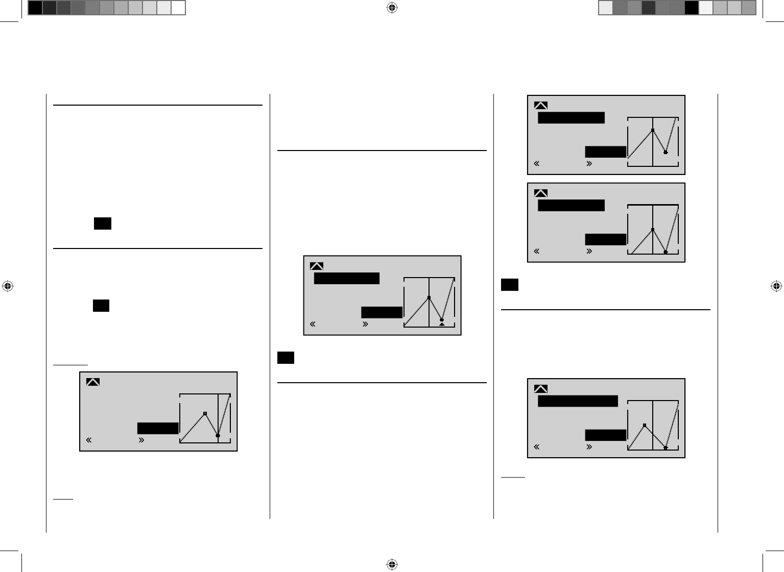
120 Detail program description - Control adjust
Deleting reference points
To delete one of the reference points (1 to max. 4), use
the joystick to move the vertical line into the vicinity
of the reference point in question. As soon as the
reference point number and its associated value is
shown on the "Point" line (see screen image above),
you can activate the value fi eld on the "Point" line to
highlight it by simultaneously tapping the cd or ef
keys on the right touch pad (CLEAR) and then delete
the value. Complete the operation by briefl y tapping the
center key ESC on the left touch pad.
Changing reference point values
Move the joystick into the range of the reference point
that is to be changed: "L" (low), 1 … 4 or "H" (high).
The number and current curve value of this point are
displayed. Activate the value fi eld by briefl y tapping
the center SET key on the right touch pad. The point
value fi eld is now highlighted and can be set within the
range -125% to +125%, and without infl uencing the
neighboring reference points.
Example:
2
+50%
–75%
–75%
Normal
off
Input
Output
Point
C1 Curve
Curve
In this sample screen image, reference point "2" has
been set to -75%.
Note:
If the joystick does not coincide with the exact reference
point, please note that the percentage value on the
"Output" line always relates to the current joystick
position.
Trim point function
Alternatively, assuming the value fi eld is active, i. e.
highlighted, you can use the up or down arrow keys
ef on the left touch pad to jump to reference points
already set. In this case, a triangle is shown on the
graph to indicate each point jumped to. The arrow keys
on the right touch pad can then be used to change the
reference point jumped to as described above, entirely
independently of the control position:
2
+50%
–75%
–75%
Trim point
Normal
Input
Output
Point
C1 Curve
Exit from trim point function setting by tapping the center
ESC key on the left touch pad.
Trim offset function
Assuming the value fi eld is active, i. e. highlighted, you
can not only use the up or down arrow keys ef on the
left touch pad to jump to reference points already set
and change their values, but you can also use the cd
keys on the left touch pad to vertically reposition an
existing curve within the range ±25%:
1
0%
+50%
+50%
Trim offset
Normal
Input
Output
Point
C1 Curve
1
0%
0%
0%
Trim offset
Normal
Input
Output
Point
C1 Curve
You can also exit from this function by tapping the center
ESC key on the left touch pad.
Trim x-axis function
This function is activated by tapping the left (e) or right
(f) arrow key n the right touch pad with an active (i. e.
highlighted) value fi eld. You can then use the arrow
keys on the right touch pad to reposition the active point
horizontally or vertically as you wish.
?
0%
–33%
0%
Trim X-axis
Normal
Input
Output
Point
C1 Curve
Notes:
If you reposition the point horizontally further away •
from the current control position than approx. ±25%,
a "?" sign re-appears in the line. This question mark
121
Detail program description - Control adjust
does not refer to the repositioned point, however:
instead, it signifi es that a further point can be set at
the current control position.
Please note that the percentage value on the •
"Output" line always relates to the current joystick
position and not to the position of the point.
Smoothing the Channel 1 curve
In the example below, sample reference points have
been set:
Reference point 1 to 0%
Reference point 2 to +25%
Reference point 3 to -75%
as described in the last section.
1
–50%
0%
0%
Normal
off
Input
Output
Point
C1 Curve
Curve
This "jagged" curve profi le can be smoothed
automatically simply by pressing a button.
First – assuming a situation is confi gured as presented
above – tap the center ESC button on the left touch pad
to deactivate the value fi eld. Then use the arrow keys on
the left or right touch pad to move the marker frame in
an upwards direction to the "Curve" line. Now briefl y tap
the center SET key on the right touch pad to activate the
value fi eld on the "Curve" line:
1
–50%
0%
0%
off
Normal
Input
Output
Point
C1 Curve
Curve
Use the arrow keys on the right touch pad to set the
curve value from "off" to "on" and complete this setup
procedure by briefl y tapping the center SET key on the
right touch pad or the center ESC key on the left touch
pad:
1
–50%
0%
0%
on
Normal
Input
Output
Point
C1 Curve
Curve
Note:
The curves shown here are for demonstration purposes
only and are not at all representative of real throttle/
airbrake curves. For real-world application examples,
see the programming examples on pages 242 and 285.
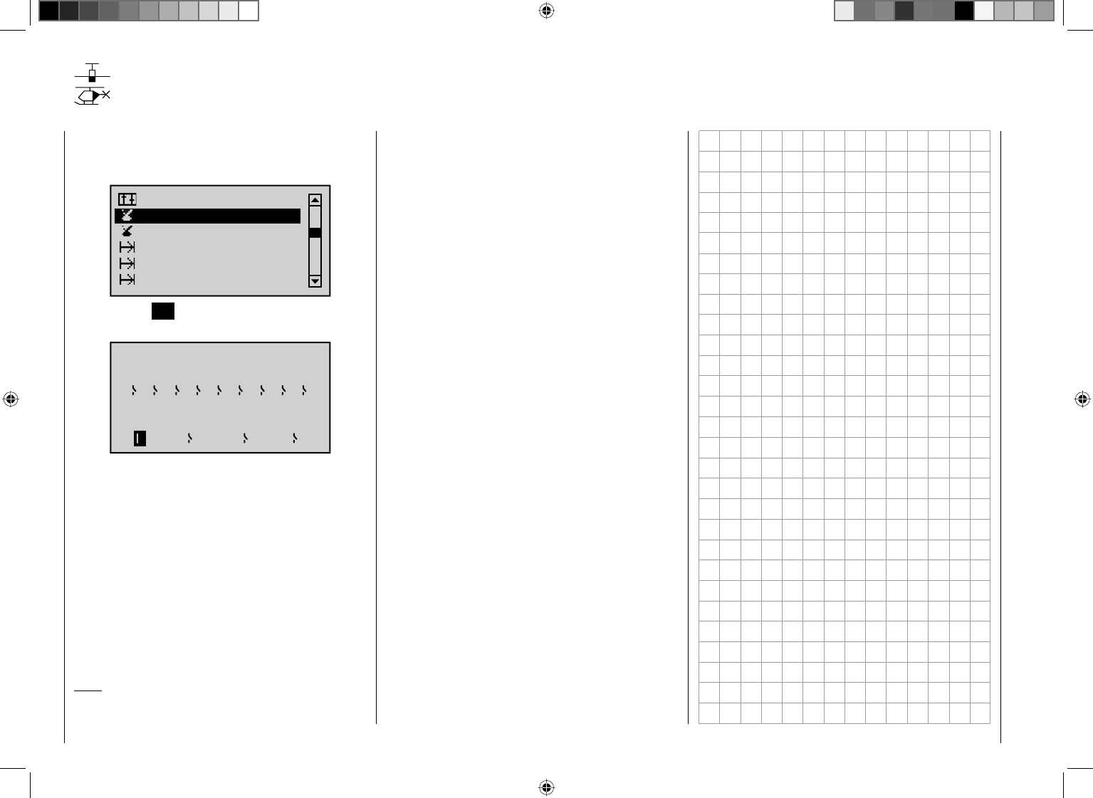
122 Detail program description - Control adjust
Switch display
Displaying switch positions
Using the arrow keys on the left or right touch pad,
page to the menu option "Switch display" in the multi-
function list:
Switch display
Control switch
Channel 1 curve
Phase settings
Phase assignment
Phase trim
Tap the center SET key on the right touch pad to open
the menu shown below:
Switch
Control Switch
1 2 3 4 5 6 7 8 9
C1 C2 C3 C4
This feature is used to check the functions and give an
overview of SW switches 1 … 9 and the programmable
control switches.
If a switch is pressed, the switch number is revealed by
one of the display items changing from an OFF to an ON
symbol (or vice versa). To improve the legibility of this
screen, a closed switch fi eld is also shown highlighted
(i. e. it is shown on a dark background).
For control switches C1 … C4, activation of the
corresponding transmitter control – which must have
been previously assigned on the "Control switch" menu
– will reveal the control switch number and direction.
Note:
The switch numbering 1 to 9 as shown here
corresponds to the labeling of the switches on the
transmitter housing. The numbering of the switches
has no effect on the programming of the transmitter,
however.
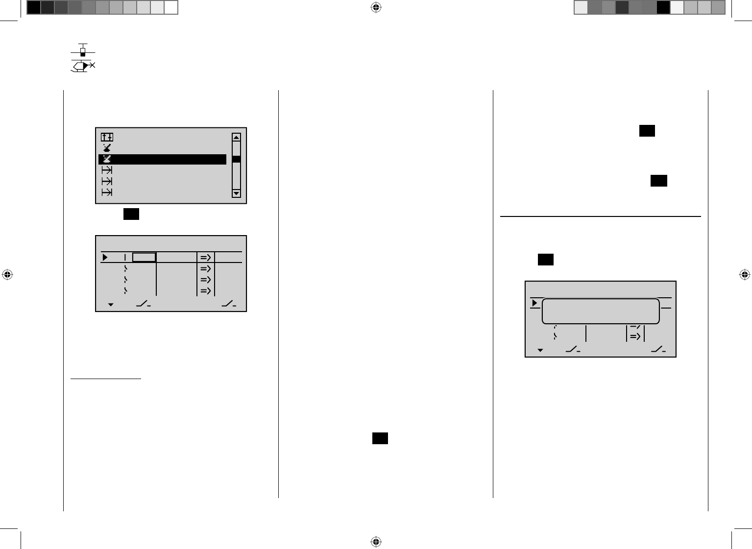
123
Detail program description - Control adjust
Control switches
Programming the control switches
Using the arrow keys on the left or right touch pad,
page to the menu option "Control switch" in the multi-
function list:
Switch display
Channel 1 curve
Phase settings
Phase assignment
Phase trim
Control switch
Tap the center SET key on the right touch pad to open
the menu shown below:
SEL
0%
0%
0%
C1
C2
C3
–––
C4
CONTROL SWITCH
Gb1
Gb1
0%
STO
–––
–––
–––
With many functions, it makes sense not to trigger
their actuation by using one of the normal switches,
but to trigger them automatically by the specifi c, freely
programmable position of a transmitter control or joystick.
Typical applications:
Activation or deactivation of an onboard glowplug •
heating system depending on carburetor setting or
motor speed (in this case, the switch for glowplug
heating is controlled on the transmitter by a mixer)
Switching a stopwatch on or off to measure the •
simple running time of electric motors
Automated switch-off of a combi "aileron • ¼ rudder"
mixer when extending the airbrakes, e. g. so as to
match the bank attitude of the model to the ground
slope when landing on a ridge, without the direction
of fl ight also being affected by the rudder (if the mixer
were active).
Lowering landing fl aps, adjusting elevator trim and/•
or executing specifi c Dual Rate, Exponential and
Differential switchings when coming in to land, as
soon as the throttle joystick is moved beyond the
switching point. If required, a control switch can be
overridden using a separately assigned switch in the
5th column.
The mc-32 HoTT program is equipped with a total of
4 of these control switches ("C1" to "G4").
Accordingly, anywhere where switches can be assigned
you have the option not only of using the 9 possible
transmitter switches, but also of choosing and assigning
one of the "C1" … "C4" control switches from the list
of expanded switches – as described in the section
"Assigning transmitter controls, switches and control
switches" on page 52.
Furthermore, combining a control switch with an
additional switch (as described later) also permits more
complex switching permutations.
Basic procedure:
If no transmitter control is assigned, the 1.
corresponding input fi eld in the column above the left
switch icon will be displayed empty.
Using the arrow keys on the left or right touch pad, 2.
select the line for the control switch you want (1 to 4).
Briefl y tap the center 3. SET key on the right touch pad.
Move your selected transmitter control.4.
The associated transmitter control number appears
in the input fi eld of the column above the left switch
icon.
Using the arrow keys on the left or right touch pad, 5.
move to the right and the column above STO.
Move the transmitter control to the desired switching 6.
point and then briefl y tap the center SET key on the
right touch pad to save the switching point.
Complete the remaining settings such as switching 7.
direction, etc.
Exit from the menu by using the center 8. ESC key on
the left touch pad.
Assigning a transmitter control to a control switch
Using the arrow keys on the left or right touch pad,
select your chosen line (1 to 4). After completing the
activation of transmitter control assignment by tapping
the center SET key on the right touch pad, the following
message is shown:
SEL
+75%
0%
0%
G1
G2
C3
–––
C4
CONTROL SWITCH
Gb1
Gb1
–75%
STO
–––
–––
–––
Move desired
control adj.
As an example, the CTRL 6 proportional rotary control
on the upper left is now to be assigned to the "C3"
control switch. Accordingly, turn the dial of this control in
any direction you want. As soon as this is detected, the
control name appears on the display:
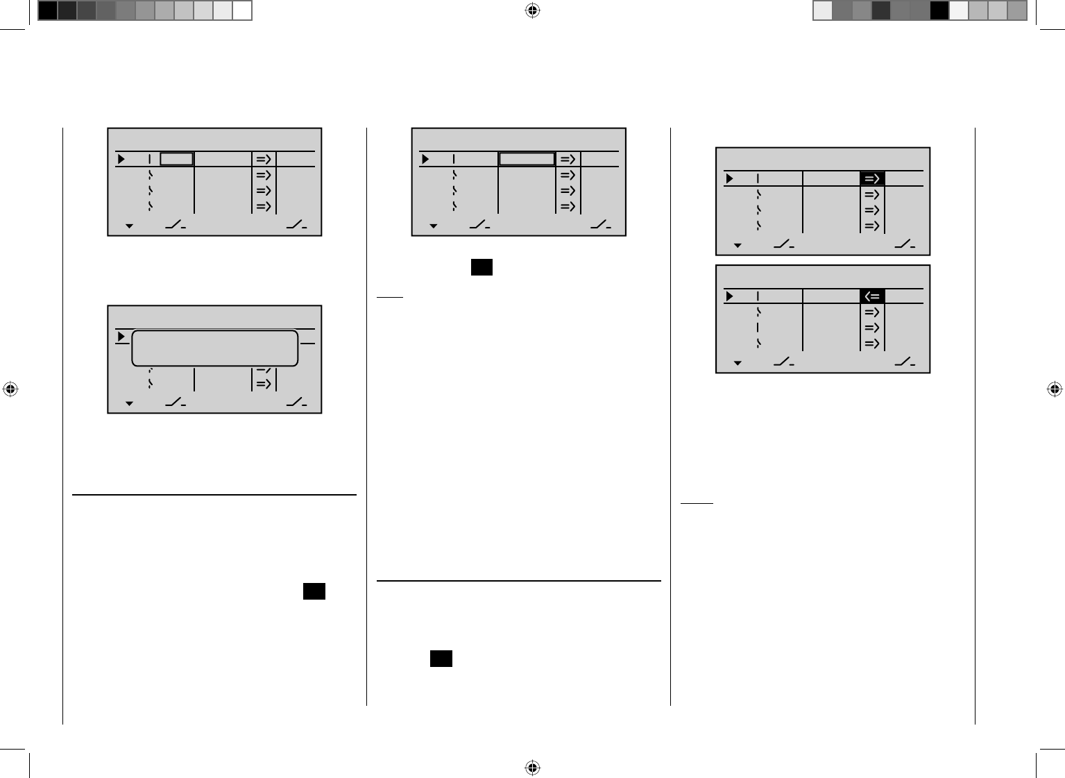
124 Detail program description - Control adjust
SEL
0%
0%
0%
C1
C2
C3
–––
C4
CONTROL SWITCH
0%
STO
–––
–––
–––
Ct6
Resetting a control switch back to "free"
To reset a control switch back to "free", make sure the
display is as below …
SEL
+75%
0%
0%
G1
G2
C3
–––
C4
CONTROL SWITCH
Gb1
Gb1
–75%
STO
–––
–––
–––
Move desired
control adj.
… and then press the cd or ef keys on the right
touch pad (CLEAR) briefl y to erase the transmitter
control assignment.
Defi ning the switching point
Using the arrow key f on the left or right touch pad,
move the marker frame into the STO (i.e. the STOre)
column.
Move the selected transmitter control to the position at
which the switching point – i. e. the switch between OFF/
ON – should trigger and briefl y tap the center SET key
on the right touch pad. The current position is displayed,
for example "+85%":
SEL
0%
0%
0%
C1
C2
C3
–––
C4
CONTROL SWITCH
+85%
STO
–––
–––
–––
Ct6
The switching point can be altered at any time by
tapping the center SET key on the right touch pad again.
Note:
Do not, however, set a switching point at a transmitter
control's travel end-point, since this makes reliable
switching impossible. Where a 3-stage switch (CTRL 9
and 10) is used to operate a control switch you should
therefore program the switching point beforehand using
one of the proportional rotary controls (CTRL 6 to 8):
First, assign the corresponding proportional control in
the 2nd column and set the switching point in such a
way that will ensure the subsequent confi guration for
the 3-stage switch will reliably exceed this value. If you
do not, the switching function will be unreliable, since
the control switch triggers only if a value unambiguously
fails to meet or exceeds the value set! To complete the
procedure, de-assign the transmitter control and then
assign the 3-stage switch.
Setting the switching direction
The switching direction of the control switch is changed
as required in the 4th column. Using the arrow key f on
the left or right touch pad, move the marker frame into
the SEL (i.e. the SELect) column. After briefl y tapping
the center SET key on the right touch pad, you can then
use the arrow keys on the left or right touch pad to set
the switching direction from "normal" to "reversed" and
vice versa:
SEL
0%
0%
0%
C1
C2
C3
–––
C4
CONTROL SWITCH
+85%
STO
–––
–––
–––
Ct6
SEL
0%
0%
0%
C1
C2
C3
–––
C4
CONTROL SWITCH
+85%
STO
–––
–––
–––
Ct6
Tapping the cd or ef keys on the right touch pad at
the same time (CLEAR) will reset the switching direction
to "=>".
The current switch position of the control switch is
displayed in the leftmost column by the switch icon next
to the number of the control switch.
Notes:
In this example, control switch "C1" remains open •
while transmitter control 6 (the throttle limiter for
a heli) is at less than +85% of full travel. It closes
once the switching point is exceeded, i.e. by a value
between +85% and the upper travel end-point.
In the above example with the switching direction •
reversed, control switch "C1" remains closed while
the transmitter control is at less than +85% of full
travel. As soon as the switching point is exceeded –
in this example, by a value between +85% and the
upper travel end-point – "C3" opens.
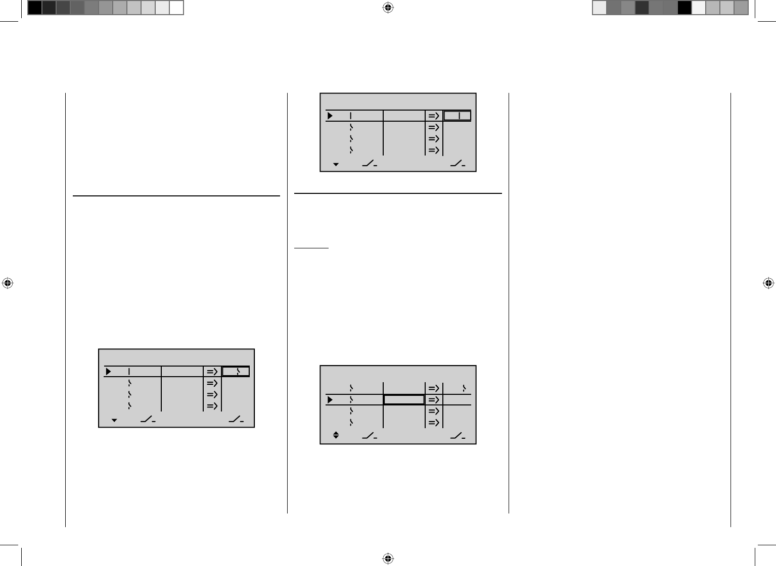
125
Detail program description - Control adjust
FIf a control switch – e. g. "C1" – has multiple •
assignments, you should bear in mind that the
switching direction set here applies to all C3
switches.
The switch state can also be inverted by reversing •
the control on the "Control adjust" menu.
Combining a control switch with one of the SW 1 …
9 switches
The control switch can be overridden by a further switch,
so that e. g. in certain fl ight situations the function to be
triggered can be activated independently of the control
position and thus the position of the control switch.
Switch to the value fi eld in the 5th column, the column
above the right switch icon. In the simplest case, select
one of the switches SW 1 … 9 as described under
"Assigning transmitter controls, switches and control
switches" on page 52. The number of this switch, e. g.
"2", appears on the display screen in the rightmost
column, together with a switch icon that indicates the
current state of the switch:
SEL
05%
05%
0%
C1
C2
C3
–––
C4
CONTROL SWITCH
Ct6 +85%
STO
2
–––
–––
While this switch is open, the "C1" control switch is
active, i. e. it triggers at the switching point; if the switch
is closed, the control switch now remains permanently
closed as well, independently of the control position and
switching direction:
SEL
0%
0%
0%
C1
C2
C3
–––
C4
CONTROL SWITCH
–75%
STO
2
–––
–––
Ct6
Combining two control switches
For more complex applications, however, it can prove
necessary to override this control switch with a second
control switch.
Example:
Instead of being assigned the CTRL 6 control as
before, the "C1" control switch is now assigned control
function 3 (transmitter control 3). The switching point
is at its center point, i.e. at 0%. The switch chosen in
the rightmost column is "C2", from the list of expanded
switches. We now assign one of the two center
proportional rotary controls to this control switch "C2",
on its own line – e. g. the right CTRL 8, whose switching
point lies at +50%:
SEL
0%
0%
+50%
C1
C2
C3
–––
C4
CONTROL SWITCH
STO
–––
–––
Ct3 C2
Ct8
0%
Reading the switching directions given in the 4th column
of the display, control switch "C3" remains closed while
the joystick (K3) and/or "transmitter control 9" is/are
beyond the switching point.
This diversity of switching options certainly offers you
enough scope for specialized applications to suit any
type of model.
126 Detail program description - Control adjust
How do I program a fl ight phase?
The concept of fl ight phase programming
General information on fl ight phase programming
During a fl ight, you will often want to apply different
settings – e.g. fl ap or trim settings for a fi xed-wing
aircraft or collective pitch and throttle servo settings for
a helicopter – at particular times in the fl ight (e. g. take-
off, approach, hover, auto-rotate, etc.). With mc-32
HoTT, you can access such presets automatically using
switches or control switches.
Flight phases are also of great utility during fl ight testing.
You can confi gure various set-ups and then switch
between them during the fl ight: this enables you to
identify the most appropriate program set-up for your
model quickly and easily.
The basic programming procedure is a three-stage
process
First, you have to set up the different fl ight phases, 1.
i. e. you assign names to phases 1 … max. 7. Each
name is then shown in all phase-specifi c menus and
also on the basic display. To avoid abrupt transitions
when switching between the various phases, you can
also program a period of time during which a "soft"
transition to the next phase takes place.
For fi xed-wing aircraft programs, these settings
are made in the "Phase settings" menu. For heli
programs, you either start with the "Base setup
model" menu if you wish to set up autorotation or,
if not, you also start programming with the "Phase
settings" menu.
In the second stage, you use the "2. Phase
assignment" menu to set up the required "phase
switches".
Once these are set, you can then move to the fl ight 3.
phase-dependent menus (see the tables below) to
start programming the settings for the individual fl ight
phases.
List of fl ight phase-relevant menus for fi xed-wing
programs:
Menu Page
"Control adjust"96
"Dual Rate / Expo" 108
"Channel 1 curve" 116
"Phase settings" 128
"Phase assignment" 134
"Phase trim" 136
"Non-delayed channels" 137
"Fl. phase timers" 142
"Wing mixers" 146
"MIX active/phase" 192
List of fl ight phase-relevant menus for helicopter
programs:
Menu Page
"Control adjust" 100
"Dual Rate / Expo" 112
"Channel 1 curve" 119
"Phase settings" 132
"Phase assignment " 134
"Non-delayed channels" 137
"Fl. phase timers" 142
"Helicopter mixers"164
"MIX active/phase"192
All other menus are model-specifi c and thus cannot
be programmed separately for each fl ight phase.
Accordingly, changes you make in all other menus apply
uniformly to all fl ight phases for that specifi c model.
In some cases you may wish to use the "Suppress
menus" menu (see page 67) to remove the non-specifi c
menus from the multi-function list when programming
fl ight phases. A practical example of fl ight phase
programming can be found on page 256).

127
Detail program description - Control adjust
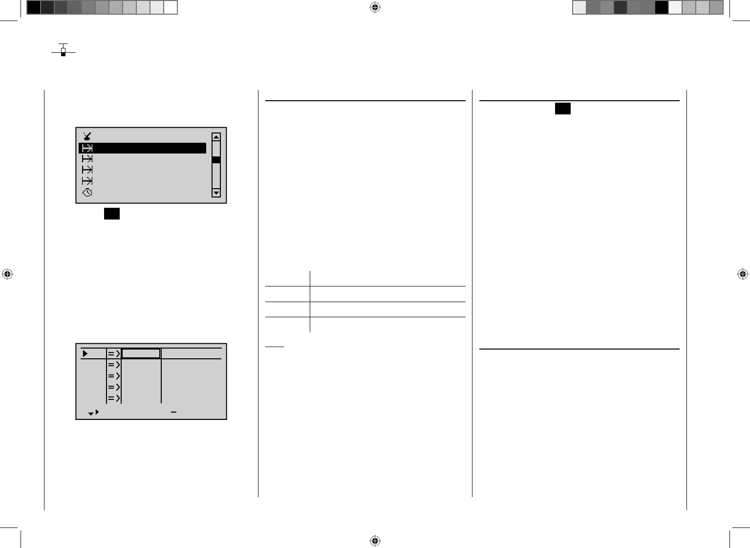
128 Detail program description - Control adjust
Phase settings
Setting up fl ight phases
Setting up fl ight phases
When you set up fl ight phases for fi xed-wing aircraft
models, you start with this menu. You assign individual
phases a name and also assign a period of time for a
(soft) transition into each phase. Note that – depending
on your model and your settings – switch times much
longer than the default 0.1 s have proven useful. You can
also set up several phases with names and transition
times even if you don't currently have a use for them,
since the decision as to which of the "occupied" phases
you activate is made only on the "Phase assignment"
menu, (page 134) when setting "phase switches".
The "Status" column, second from the left, shows which
one of the phases 1 … 7 has already been assigned to
a switch, plus the current status of that switch:
Symbol Meaning
– No switch assigned
+ Phase can be accessed via switch
¾Indicates the phase currently active
Note:
The "Copy fl ight phase" option on the "Copy / Erase"
menu is a useful aid when programming the various
fl ight phases. First, you need to determine the
parameters for a specifi c fl ight phase; these are then
copied to the next fl ight phase, where they can then be
modifi ed as appropriate.
Using the arrow keys on the left or right touch pad,
page to the menu option "Phase settings" in the multi-
function list:
Phase settings
Phase assignment
Phase trim
Control switch
Timers (general)
Non-delayed chan
Tap the center SET key on the right touch pad to open
this menu.
Within one model memory, the mc-32 HoTT lets you
program up to 7 discrete groups of settings for various
conditions met during the fl ight. The grouped settings
are typically termed "fl ight phases" and are programmed
in the corresponding menus.
Depending on the setting "Throttle min. forward/back"
or "None" in the "Motor on C1" line of the "Model type"
menu, your transmitter's display will look as follows after
accessing the "Phase settings" menu …
S1
S2
S3
Rev cent +
trv
0%
0%
0%
100% 100%
100% 100%
100% 100%
0%
0%
100% 100%
100% 100%
S4
S5
… either the columns "Motor" and "Sw. time" (switch
time) to the right of the column "ph. Tim." (fl . phase
timers) or only the column "Sw. time" will be available for
your settings.
"Name" column
Briefl y tap the center SET key on the right touch pad
and use the arrow keys on the left or right touch pad to
assign the phases your require – phase 1 to max. phase
7 – appropriate names from the selection list.
The order in which phases 1 to max. 7 are assigned is
entirely irrelevant and you can leave gaps as you wish.
Nonetheless, you should always start with "Phase 1",
the "Normal phase", which is always active if …
no phase switch is set on the "•Phase assignment"
menu or if
no phase has been assigned to specifi c combinations •
of switches.
The defi nition of the phase name "Normal" could
therefore be a useful one to adopt for "Phase 1".
The names themselves have absolutely no technical
signifi cance for programming; their only purpose is to
help you to identify which phase is active at any time
and are thus displayed in all fl ight phase-dependent
menus and also on the transmitter's basic display.
"ph. Tim." column
In addition to the standard timers on the basic screen
display, other timers are also available, whose settings
are confi gured on the "Fl. phase timers" menu
(page 142).
Clk 1, Clk 2, Clk 3, Lap, Time1, Time2
The fl ight phase timers "Clk 1 … 3" plus "Time1" and
"Time2" run only in the fl ight phase to which they have
been assigned in this menu. During other fl ight phases
they are stopped (and hidden) and the assigned stop/
start switch then has no effect.
The lap counter, once started, continues to run through
129
Detail program description - Control adjust
changes of phase, however, although it can be stopped
during any fl ight phase via the center ESC key on the
left touch pad.
While you can obviously record lap times using "Lap"
and a switch (SW), the two timers "Time1" and "Time2"
have the following meaning:
Time1 Only the times are measured at which the switch
or control switch assigned in the "Lap timer/
timer" line of the "Fl. phase timers" menu (see
page 142) is "closed". The frequency at which
the switch is activated is shown on the basic
display. This counter fi eld is highlighted as soon
as the switch for the "Time1" timer is "opened",
i. e. the timer is stopped:
GRAUBELE
#01
2:22h
Stop
Flt
«Speed »
K78
0:00
0:00
5.5V
5.2V 0:00.0
M
Lap 00
If required, you can then use the arrow keys to
access and read the times at which switches
were made.
Application:
Measurement of e. g. motor switch-on times, if
the same switch also actuates the motor.
Time2 "Time2" stores both the "Off" and the "On" times
for the associated switch, i. e. each actuation of
the switch restarts the time count again and the
counter is incremented by "1".
Each time count can be stopped by using the
center ESC key on the right touch pad, without
activating the switch itself. Activating the switch,
in turn, increments the counter by 1 and restarts
the "Time2" timer.
In order to read out the time memory by using the
arrow keys, the "Time2" timer must fi rst be stopped
by using the ESC key on the right touch pad.
Application:
In addition to the motor runtimes, for example,
the unpowered glide times between these could
also be recorded.
Tapping the cd or ef keys on the right touch pad at
the same time (CLEAR) will reset the display of stopped
timers on the basic display.
"Motor" column
Note:
This column is only available if "Forward/back" is
entered on the line "Motor on C1" on the "Model type"
menu.
Pha1
Pha2
Pha3
Name motor
Pha4
Pha5
¾
+
+
Normal
Launch
Dist.
–
–
yes
yes
yes
yes
yes
"Yes" The motor connected to receiver output 1 will
be controlled by the C1 joystick (throttle/brake
stick).
The brake system to be set up on the "Wing
mixers" menu is deactivated:
BRAKE SETTINGS
normal
Normal
off
"No" The motor connected to receiver output 1
is decoupled from the C1 joystick (throttle/
brake stick) and is held in its OFF position –as
specified by the setting "Throttle min. forward /
back" – automatically.
The brake system to be set up on the "Wing
mixers" menu is activated and is actuated by
the C1 joystick.
Elevat curve
BRAKE SETTINGS
AILE
Crow
D.red
0%
0%
0%
0%
0%
0%
WK WK2
Normal
Note:
The settings available depend on the number of control
surface servos selected on the line "Ailerons/Camber-
changing fl aps in the "Model type" menu.
"Sw. time" column
When you switch between fl ight phases, it is advisable
to use this column to program a switch time for a "soft"
transition INTO (!) the respective phase. Accordingly,
there is also the option of specifying different times for
different switches – e. g. from a phase into Phase 3 and
the same phase into Phase 1.
130 Detail program description - Control adjust
Using the arrow key f on the left or right touch pad,
move the marker frame over the "ph. Tim." column – and
"Motor" column, if applicable – to the right.
Pha1
Pha2
Pha3
Name Sw.time
Pha4
Pha5
¾
+
+
Normal
Launch
Dist.
–
–
0.1s
0.1s
0.1s
0.1s
0.1s
Briefl y tap the center SET key on the right touch pad to
highlight the value fi eld. You can then select switch times
between 0 and 9.9 s in this fi eld.
Example:
Pha1
Pha2
Pha3
Name
Pha4
Pha5
¾
+
+
–
–
3.0s
2.0s
4.0s
0.1s
0.1s
Sw.time
Normal
Launch
Dist.
The switch time is set to 4.0 s when switching from any
phase to Phase 1 "Normal".
When switching from e. g. Phase 1 to Phase 3, the
switch time is set to 2.0 s and to 3.0 s when switching
from Phase 1 or 3 to Phase 2 "Launch".
Such asymmetric transition times can be useful when
(e. g.) switching between highly contrasting fl ight phases,
such as e. g. between aerobatics and normal fl ight.
Tapping the cd or ef keys on the right touch pad at
the same time (CLEAR) will reset the time to 0.1 in the
active value fi eld.
Note:
The "switch time" set here applies uniformly to all
settings that are specifi c to fl ight phases, and thus to
all mixers activated in the "Wing mixers" menu (see
page 146). Accordingly, the transition between fl ight
phase-specifi c mixers does not occur abruptly. If you
want individual servos to be switched without a delay,
however, defi ne these accordingly in the "Non-delayed
channels" menu (see page 137).

131
Detail program description - Control adjust
132 Detail program description - Control adjust
Using the arrow keys on the left or right touch pad,
page to the menu option "Phase settings" in the multi-
function list:
Phase settings
Phase assignment
Control switch
Timers (general)
Non-delayed chan
Fl. phase timers
Tap the center SET key on the right touch pad to open
the menu shown below:
Auto
Pha1
Pha2
Name ph.Tim.
Pha3 –
–
–
–
Pha4
¾Autorot
Within one model memory, the mc-32HoTT lets you
program up to 6 discrete groups of settings for various
conditions met during the fl ight. These are in addition to
the auto-rotation flight phase that can be set up in the
"Base setup model" menu. The grouped settings are
typically termed "fl ight phases" and are programmed in
the corresponding menus.
Setting up fl ight phases
When you set up fl ight phases for helicopter models,
you start with this menu. You assign individual phases
a name and also assign a period of time for a (soft)
transition into each phase. Note that – depending on
your model and your settings – switch times much longer
than the default 0.1 s have proven useful. You can also
set up several phases with names and transition times
Phase settings
Setting up fl ight phases
even if you don't currently have a use for them, since
the decision as to which of the "occupied" phases you
activate is made only on the "Phase assignment" menu
(page 134) when setting "phase switches".
The "Status" column, second from the left, shows which
one of the phases 1 … 6 has already been assigned to
a switch, plus the current status of that switch:
Symbol Meaning
– No switch assigned
+ Phase can be accessed via switch
¾Indicates the phase currently active
Note:
The "Copy fl ight phase" option on the "Copy / Erase"
menu is a useful aid when programming the various
fl ight phases. First, you need to determine the
parameters for a specifi c fl ight phase; these are then
copied to the next fl ight phase, where they can then be
modifi ed as appropriate.
"Name" column
The fi rst line, and thus the fl ight phase with top priority,
is reserved for auto-rotation fl ight – see the "Base setup
model" menu. Accordingly, the predefi ned name cannot
be changed.
Use the arrow keys to move to the line "Pha1". Briefl y
tap the center SET key on the right touch pad and use
the arrow keys on the left or right touch pad to assign
each of the phases your require – phase 1 to max.
phase 6 – an appropriate name from the selection list.
The order in which phases 1 to max. 6 are assigned is
entirely irrelevant and you can leave gaps as you wish.
Nonetheless, you should always start with "Phase 1",
the "Normal phase", which is always active if …
no phase switch is set on the "•Phase assignment"
menu or if
no phase has been assigned to specifi c combinations •
of switches.
The defi nition of the phase name "Normal" could
therefore be a useful one to adopt for "Phase 1".
The names themselves have absolutely no technical
signifi cance for programming; their only purpose is to
help you to identify which phase is active at any time
and are thus displayed in all fl ight phase-dependent
menus and also on the transmitter's basic display.
"ph. Tim." column
In addition to the standard timers on the basic screen
display, other timers are also available, whose settings
are confi gured on the "Fl. phase timers" menu
(page142).
Clk 1, Clk 2, Clk 3, Lap, Time1, Time2
The fl ight phase timers "Clk 1 … 3" plus "Time1" and
"Time2" run only in the fl ight phase to which they have
been assigned in this menu. During other fl ight phases
they are stopped (and hidden) and the assigned stop/
start switch then has no effect.
The lap counter, once started, continues to run through
changes of phase, however, although it can be stopped
during any fl ight phase via the center ESC key on the
left touch pad.
While you can obviously record lap times using "Lap"
and a switch (SW), the two timers "Time1" and "Time2"
have the following meaning:
Time1 Only the times are measured at which the switch
or control switch assigned in the "Lap timer/
timer" line of the "Fl. phase timers" menu (see
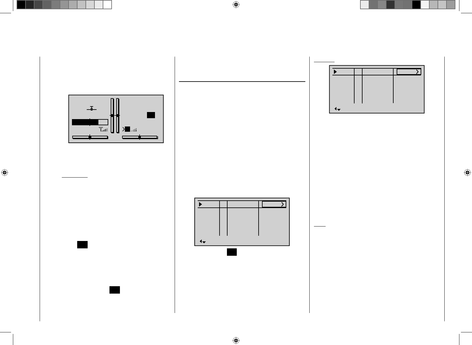
133
Detail program description - Control adjust
page 142) is "closed". The frequency at which
the switch is activated is shown on the basic
display. This counter fi eld is highlighted as soon
as the switch for the "Time1" timer is "opened",
i. e. the timer is stopped:
STARLET
#01
2:22h
Stop
Flt
«Speed »
K78
0:00
0:00
5.5V
5.2V 0:00.0
M
Lap 00
If required, you can then use the arrow keys to
access and read the times at which switches
were made.
Application:
Measurement of (e. g.) fl ight phases with
increased motor speed, if the same switch is
used to actuate fl ight phase switching.
Time2 "Time2" stores both the "Off" and the "On" times
for the associated switch, i. e. each actuation of
the switch restarts the time count again and the
counter is incremented by "1".
Each time count can be stopped by using the
center ESC key on the right touch pad, without
activating the switch itself. Activating the switch,
in turn, increments the counter by 1 and restarts
the "Time2" timer.
In order to read out the time memory by using
the arrow keys, the "Time2" timer must fi rst be
stopped by using the ESC key on the right touch
pad.
Tapping the cd or ef keys on the right touch pad at
the same time (CLEAR) will reset the display of stopped
timers on the basic display.
"Sw. time" column
When you switch between fl ight phases, it is advisable
to use this column to program a switch time for a "soft"
transition INTO (!) the respective phase. Accordingly,
there is also the option of specifying different times for
different switches – e. g. from a phase into Phase 3 and
the same phase into Phase 1.
For safety reasons, however, the transition to the auto-
rotation fl ight phase ALWAYS occurs without any time
delay. The angled bracket ">" in the "Sw. time" column at
the end of the "Auto" line indicates that a delay can be
set when transitioning FROM (!) auto-rotation INTO (!)
another phase.
Using the arrow key f on the left or right touch pad,
move the marker frame over the "ph. Tim." column to the
right.
Pha1
Pha2
Pha3
Name Sw.time
Pha4
¾
+
+
Normal
Hover
–
–
0.1s
0.1s
0.1s
0.1s
0.1s
Speed
AutorotAuto
Briefl y tap the center SET key on the right touch pad to
highlight the value fi eld. You can then select switch times
between 0 and 9.9 s in this fi eld.
Example:
Pha1
Pha2
Pha3
Name Sw.time
Pha4
¾
+
+
Normal
Hover
–
–
3.0s
2.0s
5.5s
4.0s
0.1s
Speed
AutorotAuto
A delay of 5.5 s applies when switching FROM auto-
rotation into any other phase. A delay of 0.0 s always
applies when switching TO auto-rotation.
The switch time is 3.0 s when switching from any other
phase to Phase 1 "Normal".
When switching from e. g. Phase 1 to Phase 3, the
switch time is set to 4.0 s.
Such asymmetric transition times can be useful when
(e. g.) switching between highly contrasting fl ight phases,
such as e. g. between aerobatics and normal fl ight.
Tapping the cd or ef keys on the right touch pad at
the same time (CLEAR) will reset the time to 0.1 in the
active value fi eld.
Note:
The "switch time" set here applies uniformly to all
settings that are specifi c to fl ight phases, and thus to
all mixers activated in the "Wing mixers" menu (see
page 146). Accordingly, the transition between fl ight
phase-specifi c mixers does not occur abruptly. If you
want individual servos to be switched without a delay,
however, defi ne these accordingly in the "Non-delayed
channels" menu (see page 137).
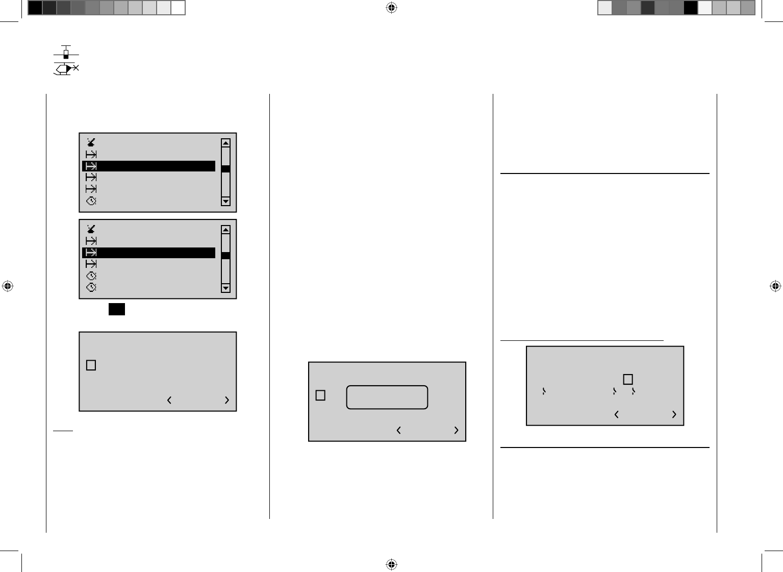
134 Detail program description - Control adjust
Phase assignment
Setting up fl ight phases
Using the arrow keys on the left or right touch pad, page
to the menu option "Phase assignment" in the multi-
function list:
Phase settings
Phase trim
Control switch
Timers (general)
Non-delayed chan
Phase assignment
Fl. phase timers
Phase settings
Control switch
Timers (general)
Non-delayed chan
Phase assignment
Tap the center SET key on the right touch pad to open
the menu shown below:
PHASE ASSIGNMENT
prior.
A B C D E F
1normal
combi
Note:
A phase name appears to the right of the phase number
at the bottom right of the display only if you have
assigned the name beforehand on the "Phase settings"
menu.
On the "Phase settings" menu – described above
separately for fi xed-wing and helicopter models – you
will have set up names for your phases. On this menu –
which is identical for both model types – you must now
specify the switches or switch combinations that you
want to use to trigger each phase. One exception for heli
menu: one of the two auto-rotation switches must be set
on the menu "Base setup model".
Please note the following priorities:
If you have not yet assigned •any fl ight phase
switches to any phase names, you will always fi nd
yourself in fl ight phase "1". Accordingly, by the time
you start programming fl ight phases, you should
therefore have already given this fl ight phase the
phase name "Normal".
Independently of the switch positions of phases •
assigned to switches using this menu, the auto-
rotation phase – applicable only to the "Helicopter"
model type and whose switch is assigned on the
"Base setup model" menu – always (!) takes
precedence. Accordingly, as soon as the auto-
rotation switch in question is activated, the following
warning appears:
A B C D E F
1normal
PHASE ASSIGNMENT
prior. combi
Autorot
Phase switch "A" is given priority over all subsequent •
switch positions, from "B" to "F"
Phase switch "B" is given priority over all subsequent •
switch positions, from "C" to "F"
The two 3-stage switches, SW 4/5 and 6/7, should •
always be assigned from the center point position.
For this reason, use switch "A" and/or switch "B" only if
you wish to change from any other fl ight phase – apart
from the heli's auto-rotation phase – directly into the
phase that is assigned to this switch.
Programming fl ight phase switches
Once you have confi gured your desired switch position,
"A" to "F", using the arrow keys on the left or right
touch pad, a switch (whether a "normal" switch or an
expanded switch) is then assigned as described in the
section "Assigning transmitter controls, switches and
control switches" (page 52).
The order in which assignment is made is irrelevant: •
you must ensure only that you assign what are, for
you, the "correct" switches. (In the heli program, for
example, you should also take care to ensure you do
not use this menu to re-assign any auto-rotation switch
already assigned on the " Base setup model" menu.)
Example: 4 fl ight phases with phase priority
A B C D E F
1 Normal
267
PHASE ASSIGNMENT
prior. combi
Assigning fl ight phases to switch positions
You have now assigned names to the fl ight phases (1
… max. 7) on the "Phase settings" menu and also
programmed switches on this menu, but … at the bottom
right of the display screen, you only see "<1 normal >" –
regardless of the positions the switches are in!?
135
Detail program description - Control adjust
Use the arrow keys on the left or right touch pad to
move the marker frame down and to the right and then
briefl y tap the center SET key on the right touch pad:
A B C D E F
267
1 Normal
PHASE ASSIGNMENT
prior. combi
Now close one (or more, as required) of the switches
that you have assigned, and assign one of the fl ight
phase names from the list you selected beforehand on
the "Phase settings" menu to this switch position or
combination.
Here, for example, we assign the "Launch" phase to the
closed ("I") priority switch "A" …
A B C D E F
267
2 Launch
PHASE ASSIGNMENT
prior. combi
… if, for example, we wish to switch to this phase
regardless of the "C" … "F" switch positions, because
the same switch activates an electric motor, etc.
Use the same approach to set the other switches or
combinations of switches.
Theoretically – for the situation where all three are
closed – you could use the three single switches shown
in the example to defi ne an additional fi fth fl ight phase
on the "Phase settings" menu. However, since this
example assumes just four fl ight phases, you can leave
the default phase name as "1 Normal" for this switch
position.
You can leave this menu in the familiar way by pressing
the center ESC key on the left touch pad.
Tips:
If you have named more phases than you currently •
have switches defi ned for then this is not really
problematic. You can repeat and change your switch
assignment as you wish at any point in time. And you
can also name additional phases at any time and
then assign switches to them.
When assigning switches, check whether the •
switches are already otherwise assigned to ensure
that you avoid duplicate assignments.
Important notice:
Before a phase switch is assigned, the model
settings confi gured are now to be found in the fl ight
phase "1 Normal", i. e. all fl ight phase-dependent
menus are reset to the standard confi gurations for
all other fl ight phases.
To avoid having to start from scratch in every fl ight
phase, you can copy over these standard settings
by using the command "Copy fl ight phase" on the
"Copy / Erase" menu to replace them with fl ight
data obtained from the "Normal" fl ight phase. You
then need only to make further fl ight phase-specifi c
changes to the settings.
136 Detail program description - Control adjust
Phase trim
Flap settings specifi c to fl ight phases
Using the arrow keys on the left or right touch pad, page
to the menu option "Phase trim" in the multi-function
list:
Phase settings
Phase assignment
Control switch
Timers (general)
Non-delayed chan
Phase trim
Tap the center SET key on the right touch pad to open
the menu shown below:
Normal
¿0%
ELEV
normal
Depending on the settings made on the "Aile/fl aps"
line from the "Model type" menu (page 82) and on the
"Phase settings" menu, this menu makes available a
set of control functions – 1 for EL …
Normal
¿0%
ELEV
Normal
… and up to 4 for EL, RU, AI and AI2 – for the
confi guration of trim settings that are specifi c to fl ight
phases. The setting of the fl ight phase switches – to be
defined beforehand on the "Phase assignment" menu
– determines the line that is chosen. An asterisk marks
the fl ight phase currently active. At the same time, the
name of the respective fl ight phase is also shown at the
bottom left of the screen. You can enter settings only for
the currently active fl ight phase, e. g.:
Normal
¿
0%
ELEV
Launch
0%
AILE
Launch
Thermal
Dist.
0% 0%
0% 0%
0% 0%
"ELEV" column In this column, you can store a phase-
specifi c elevator trim setting.
Important notice:
Settings made in this column have an
immediate effect on elevator trim and,
accordingly, the trim setting display. In
turn, the elevator trim lever affects the
values of this column either "globally"
or "phase-specifi cally", depending on
the "global/phase" setting made on the
"Elev" line of the "Stick mode" menu.
"AILE", "FLAP", "FLAP2"
The values in these columns (max. 3)
are identical to those in the "Fl.pos" (fl ap
position) line on the "Multi-fl ap menu"
within the "Wing mixers" menu. For this
reason, any changes made always affect
the other menu directly – and vice versa.
¿
0%
FLAP
0%
FLAP2
0% 0%
0% 0%
0% 0%
Normal
Launch
Launch
Thermal
Dist.
Note:
If present, you can access the "FLAP" and "FLAP2"
columns by using the arrow keys ef on the left or right
touch pad to go beyond the right edge of the screen and
back, as appropriate.
After selecting the appropriate column, by using the
arrow keys on the left or right touch pad and then
briefl y tapping the center SET key on the right touch
pad, you can then use the arrow keys to set the values
independently of one another, within a range of ±150%.
If you tap the cd or ef keys on the right touch
pad (CLEAR) at the same time, this will reset values
changed in the highlighted value fi eld back to 0%.
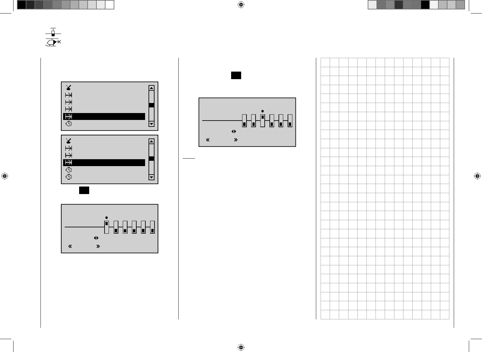
137
Detail program description - Control adjust
Non-delayed channels
Channel-dependent delays to switching
Using the arrow keys on the left or right touch pad, page
to the menu option "Phase trim" in the multi-function
list:
Phase settings
Phase trim
Control switch
Timers (general)
Phase assignment
Non-delayed chan
Phase settings
Control switch
Timers (general)
Fl. phase timers
Phase assignment
Non-delayed chan
Tap the center SET key on the right touch pad to open
the menu shown below:
NONDELAYED CHANNELS
non-delay
normal
Normal
123456
On the "Phase settings" menu, you will have set the
necessary switch times for fl ight phase transitions.
In this menu, you can now deactivate the transition delay
set previously, per fl ight phase and for individual control
channels – e. g. for the motor channel for electric models
or heading-lock systems for heli gyros, etc.
Switch over to the corresponding fl ight phase. This is
shown at the bottom left of the display.
Use the arrow keys on the left or right touch pad to
move the "z" onto the corresponding channel and then
briefl y tap the center SET key on the right touch pad.
The switch icon changes from "normal" to "non-delay"
and vice versa. For example:
NONDELAYED CHANNELS
non-delay
normal
Normal
789
10 11 12
Note:
To access channels 7 … 12, follow the description on
page 27: use the arrow keys ef on the left or right
touch pad to go beyond the right edge of the screen and
back, as appropriate.
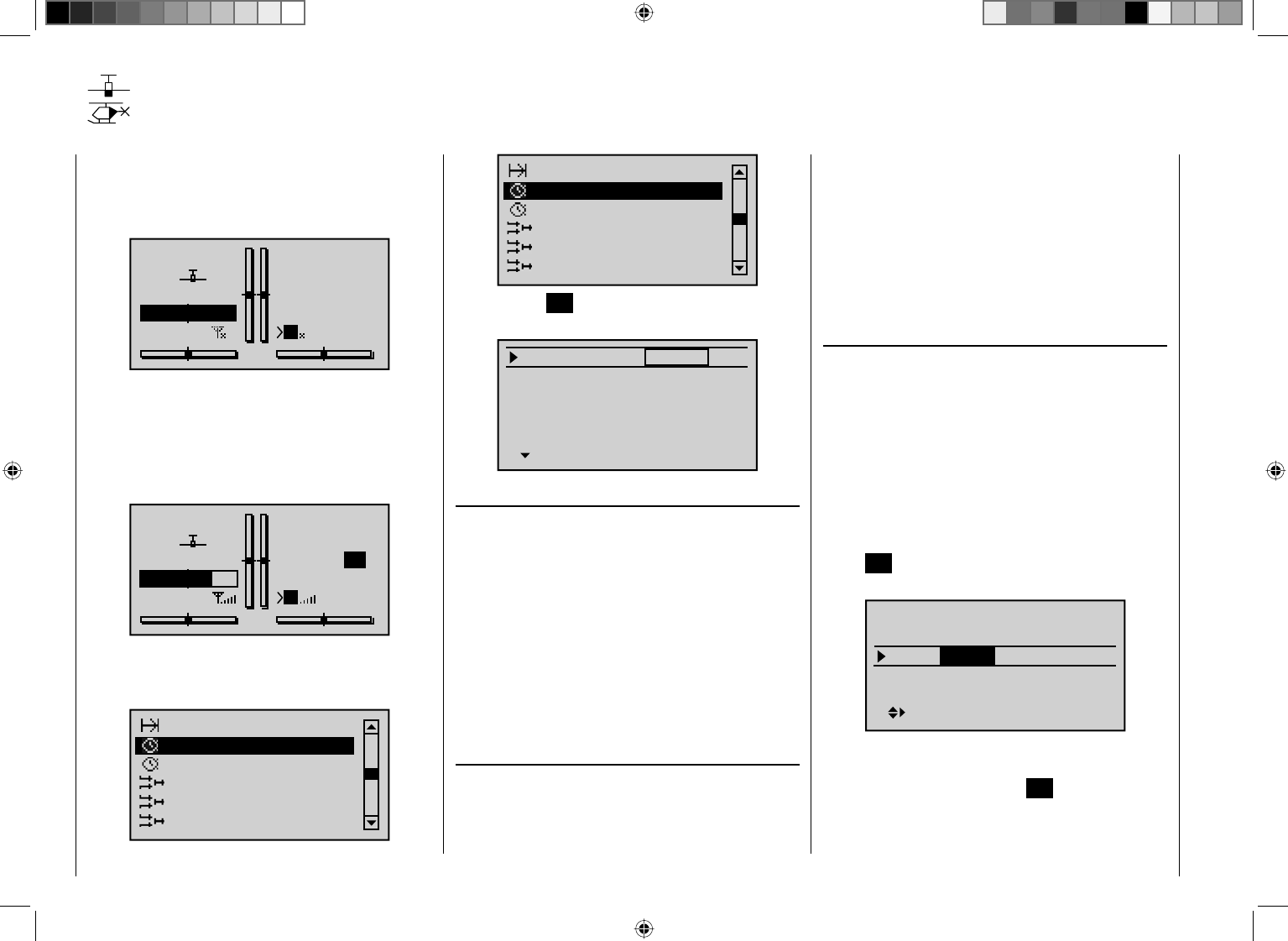
138 Detail program description - Control adjust
Timers (general)
Timers on the basic display
The default transmitter display shows a total of three
timers. These are: the transmitter operating time on the
left of the display, plus a "Top" and a "Centr" timer on the
right of the display:
GRAUBELE
#01
0:00h
Stop
Flt
K78
0:00
0:00
0.0V
5.9V
M
HoTT
A further, fl ight-phase specifi c timer can also be
confi gured, depending on your settings in the two menus
"Fl. phase timers" (page 142) and "Phase settings"
(pages 128 and 132). This optional fl ight phase timer
– such as the lap time timer – appears underneath the
"Centr" (fl ight time) timer:
GRAUBELE
#01
2:22h
Stop
Flt
«Speed »
K78
0:00
0:00
5.5V
5.2V 0:00.0
M
Lap 00
To confi gure the "Top" and/or "Centr" timer, use the
arrow keys on the left or right touch pad to access the
menu option "Timers (general)" in the multi-function list:
Non-delayed chan
Timers (general)
Fl. phase timers
Wing mixers
Free mixers
MIX active/phase
Non-delayed chan
Timers (general)
Fl. phase timers
Helicopter mixer
Free mixers
MIX active/phase
Tap the center SET key on the right touch pad to open
the menu shown below:
Model time
Batt. time
Top :
Centr:
Stop
Flight
Timer
–––12:34h
1:23h
0:00
0:00
" Model time"
This timer shows the currently recorded total access
time to the currently active model memory. If necessary,
you can also influence the automated time recording
using a switch assigned at the right of the display, and
use this switch to activate and deactivate the "Model
time" timer as required. This switch is assigned (and
erased again as required) as described in the section
"Assigning transmitter controls, switches and control
switches" on page 52.
Tapping the cd or ef keys on the right touch pad at
the same time (CLEAR) will reset the time to "0:00h".
" Batt. time"
This operating hours timer records the transmitter's
total switch-on time since the last time the battery was
charged, thus monitoring the transmitter battery. A
switch cannot be assigned to this function.
This timer is automatically reset to "0:00h" when the
transmitter detects that the voltage of the battery is
signifi cantly higher than the last time it was switched on,
e. g. as a result of a charge process or the installation of
a replacement battery.
Tapping the cd or ef keys on the right touch pad at
the same time (CLEAR) will also reset the time here to
"0:00h".
"Top" and "Centr"
These two timers are located at the top right of the basic
display (see the screen image immediately to the left)
and can be assigned a different name; their function and
mode of operation varies according to the name you
give them. Independently of the name each is given,
the "Top" and "Centr" timer can be programmed to run
any length of time forwards or backwards – see further
below.
Using the arrow keys on the left or right touch pad,
select the line for the "Top" or "Centr" timer. Tap the
center SET key on the right touch pad briefl y to activate
the selection of a timer type:
Timer
–––12:34h
1:23h
0:00
0:00
Stop
SEL
Model time
Batt. time
Top :
Centr:Flight
Now use the arrow keys on the left or right touch pad to
select your desired timer and complete your selection
by once again tapping the center SET key on the right
touch pad:
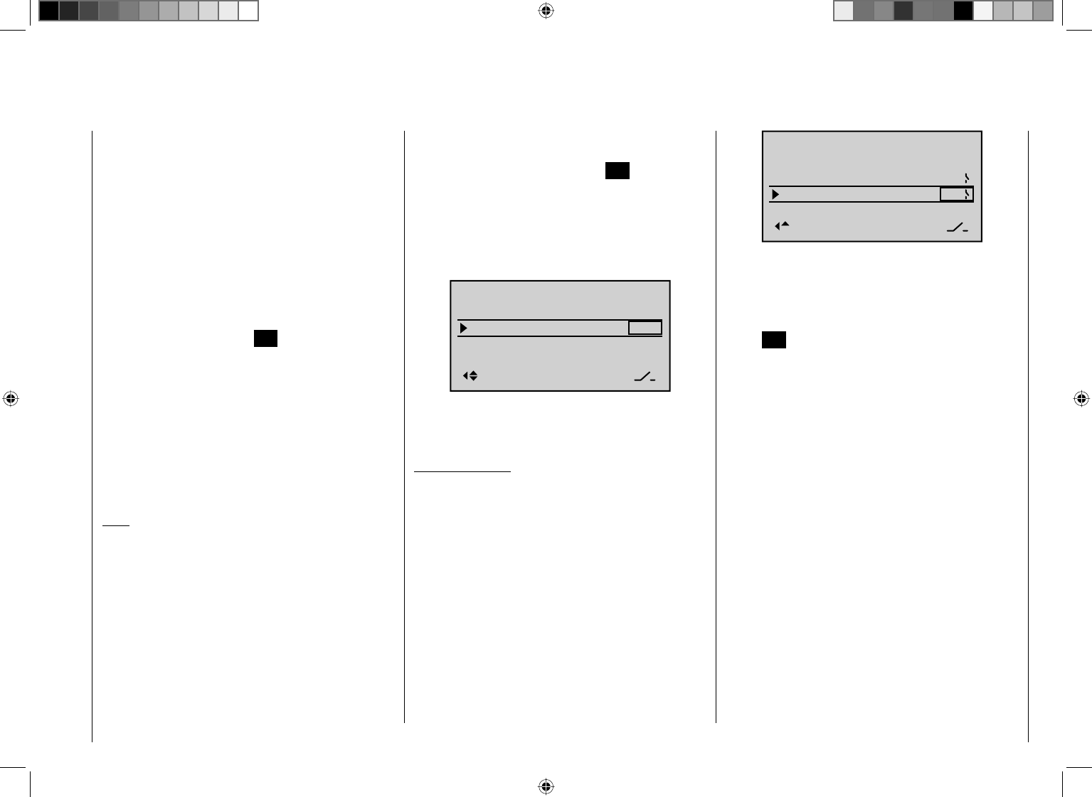
139
Detail program description - Control adjust
"Stop (watch)"or "Motor (runtime)"
Both of these two timer variants can be started and
stopped using any of the available switches.
The timer defi ned as "Stopwatch" or "Motor runtime"
sums the "ON" times continually, so that once your
aircraft has landed, you can read off the sum of all
switch "ON" times since the timer was last reset.
"Flight (time)"
This timer is designed for measuring the fl ight time: it
can be started with an assigned switch and stopped
(once the switch has been re-opened) on the basic
display by tapping the center ESC key on the left touch
pad. Once in a stopped state, it can be reset to its
starting value by tapping the cd or ef keys on the
right touch pad at the same time (CLEAR).
If you wish to assign a control switch, you must fi rst
defi ne the switch on the "Control switch" menu and
specify the switching point along the travel of the
transmitter control. As an example, the timer can then
be started by "opening the throttle" or by opening the
throttle limiter for heli models.
Note:
The combination of the fl ight time timer and stopwatch
means that you can glance at the display at any time
and see how long you have been fl ying since the timers
were started, plus the total motor runtime within this
particular period of fl ight time.
"Frame(time)"
The timeframe timer is intended primarily for use by
competition pilots, who are frequently given a timeframe
within which they must complete certain tasks. The timer
is started in precisely the same way as the fl ight time
timer. To stop the timer, fi rst ensure the timer switch is
at its OFF position. Then, press and hold the arrow keys
cde,and then press the center ESC key.
Switch assignment
Using the arrow key f on the left or right touch pad,
move the marker frame next to the triangle as shown in
the screen image shown below to the rightmost column
of the relevant line:
Alarm
–––
12:34h
1:23h
0s
0s
–––
–––
SEL
Model time
Batt. time
Top :
Centr:
Stop
Flight
Here, you assign a switch as described in the section
"Assigning transmitter controls, switches and control
switches" (page 52).
Typical application:
The "stop watch" and "fl ight timer" are both to be started
simultaneously using the C1 stick as soon as a user-
defi ned switching point is exceeded.
For this purpose, you will defi ne e.g. "C1" on the
"Control switch" menu (page 123 ). To complete the
procedure, you select this from the expanded switches
(see the section "Assigning transmitter controls,
switches and control switches" on page 52) and assign
it to both these lines:
Alarm
–––
12:34h
1:23h
0s
0s
C1
SEL
C1
Model time
Batt. time
Top :
Centr:
Stop
Flight
The stopwatch will now stop when the stick is below the
switching point and resume running above the switching
point. The same is not true for the fl ight time timer,
however, which also starts the fi rst time the switching
point is exceeded. It can be stopped (by tapping the
center ESC key on the left touch pad) only once the
stopwatch is stopped; it can then be reset to its starting
value by tapping the cd or ef keys on the right
touch pad at the same time (CLEAR).
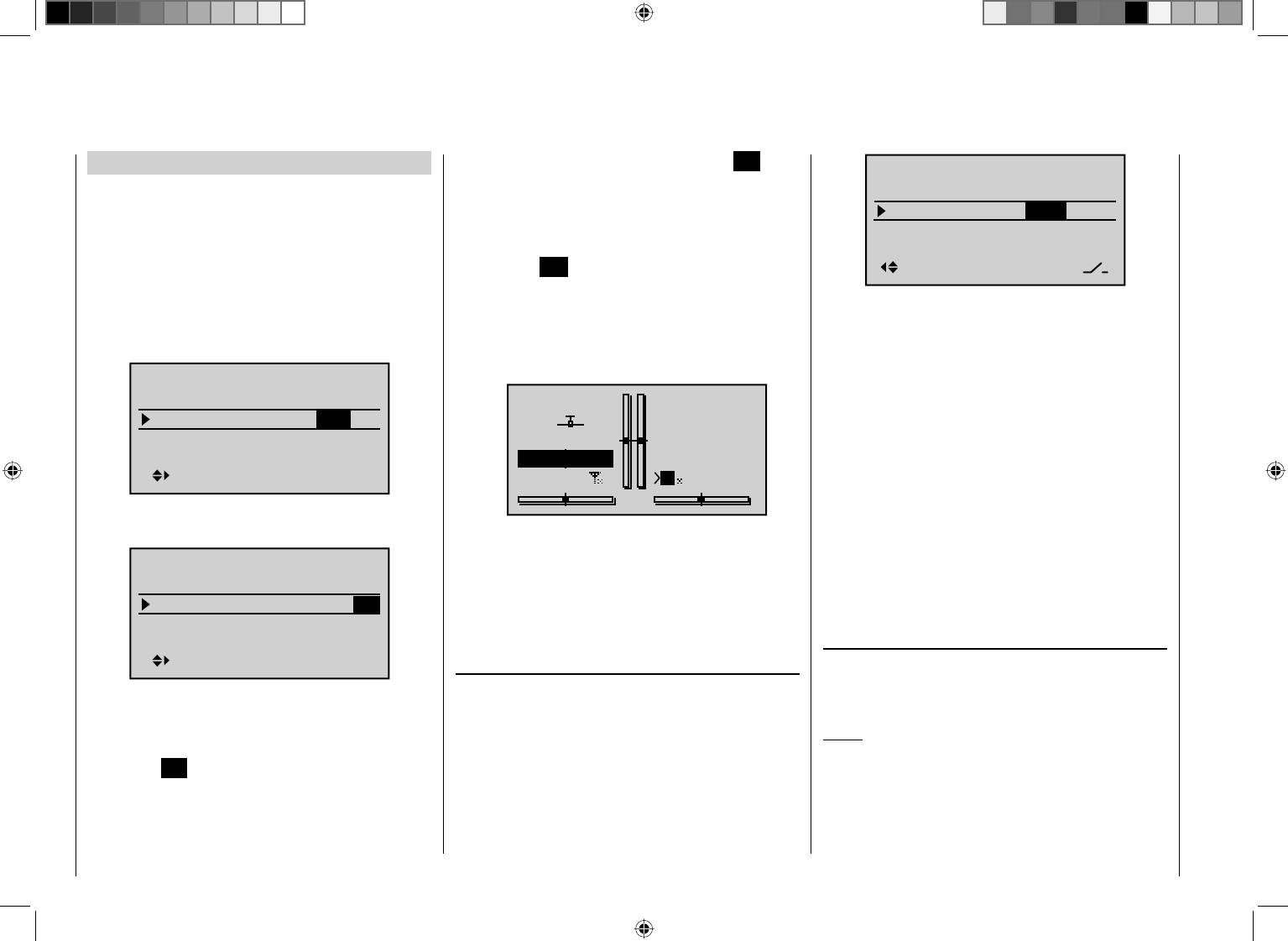
140 Detail program description - Control adjust
Switching between "forwards" and "backwards"
Timer runs forwards (stopwatch function)
Following switch assignment, if the stopwatch shown on
the basic display is started with the initial value of "0:00",
then it will run forwards for max. 180 min and 59 s and
then restart from 0:00.
Timer runs backwards (countdown function)
In the – left – minutes fi eld, select a start time between 0
and 180 min …
Timer
–––12:34h
1:23h
0:00
180:00
SEL
Model time
Batt. time
Top :
Centr:
Stop
Flight
… and in the – right – seconds fi eld, select a start time
between 0 and 59 s (or any combination of these):
Timer
–––12:34h
1:23h
180:59
0:00
SEL
Model time
Batt. time
Top :
Centr:
Stop
Flight
Procedure
Select the desired input fi eld using the arrow keys 1.
ef on the left or right touch pad.
Now tap 2. SET in the center of the right touch pad.
Make your time selection in the highlighted minutes3.
or seconds field, using the arrow keys on the right
touch pad.
Complete your input by tapping the center 4. SET key.
If you tap the 5. cd or ef keys on the right touch
pad at the same time (CLEAR), this will reset any
settings made back to "0" or "00".
After switching back to the basic display (by tapping 6.
the center ESC key on the left touch pad as many
times as required), make sure the stopwatch is
stopped and then tap the cd or ef keys on
the right touch pad (CLEAR) so that the stopwatch
switches over to the "timer" function. Look to the top
right in the following screen image:
GRAUBELE
#01
0:00h
Stop
Flt
K78
10:01
0:00
0.0V
5.9V
M
HoTT
After the assigned switch is activated, the stopwatch
starts at the initial value set and runs backwards
("countdown function"). Once the timer reaches zero it
does not stop, but continues to run to enable you to read
off the time elapsed after it reached 0:00. To make this
absolutely clear, the timer is shown highlighted.
"Alarm" timer
The "Alarm" column is accessed by using the arrow
key f on the left or right touch pad to move the marker
frame over the "Timer column to the right. In the
"Alarm" column, you can defi ne a time between 5 and
90 seconds (in 5-second increments) before zero is
reached: at this point an audible signal will be emitted,
which eliminates the need for you to check the screen
continually during the fl ight.
Alarm
–––
12:34h
1:23h
0s
–––
–––
SEL
0s
Model time
Batt. time
Top :
Centr:
Stop
Flight
If you tap the cd or ef keys on the right touch pad
at the same time (CLEAR), this will reset any settings
made back to "0 s".
Audible signal sequence
30 s before zero: Triple beep
Single beep every two seconds
20 s before zero: Double beep
Single beep every two seconds
10 s before zero: Single beep
Single beep every second
5 s before zero: Single, higher-frequency beep
every second
Zero: Extended audible signal and
screen switches to highlighted
display
Resetting timers when stopped
Tapping the cd keys on the right touch pad at
the same time (CLEAR) will reset the display of
previously stopped timers on the basic display.
Notes:
Timers that are running backwards are shown on the •
basic display with a fl ashing colon (:) between the
minutes and the seconds fi elds.
A typical application, "Timer activation via the C1 •
joystick", can be found on page 252).
141
Detail program description - Control adjust
If you change timer functionality, these changes are •
made active by pausing the timer(s) and then tapping
the cd or ef keys on the right touch pad at the
same time (CLEAR) to reset them.
Remember that the timer switches also remain active •
during programming.
On the basic display, simultaneously tapping the•
cd or ef keys on the right touch pad at the same
time (CLEAR) will reset the previously stopped timer
to its programmed initial value – see the "Alarm"
timer section.
142 Detail program description - Control adjust
Fl. phase timers
Selecting and setting
The discussion of the "Phase settings" menu on page
134 has already described how timers can be assigned
to a fl ight phase. The same section has also described
the properties of "Time1" and "Time2". This section
now proceeds to describe "Clk 1, 2 and 3", plus the "lap
counter/timetable" timer.
The additional, fl ight phase-specifi c timer selected is
displayed on the basic display underneath the "center"
timer, as shown below:
GRAUBELE
#01
2:22h
Stop
Flt
«Speed »
K78
0:00
0:00
5.5V
5.2V HoTT
M
Clk1 0:00
In this menu …
Non-delayed chan
Timers (general)
Wing mixers
Free mixers
MIX active/phase
Fl. phase timers
Non-delayed chan
Timers (general)
Helicopter mixer
Free mixers
MIX active/phase
Fl. phase timers
… you can now program "Clks 1 … 3" as stopwatches
(i. e. timers that run forward) or as countdown/alarm
timers (i. e. timers that run backwards). You can assign
any switch to these timers, and the same is true of the
"lap counter/timetable" timer:
Timer1
Timer2
Timer3
Lap time/tim tab
SEL
–––
0:00
0:00
0:00
Lap Display
0s
0s
0s
–––
–––
–––
–––
SEL
The fl ight phase timers "Clks 1 … 3" and the
"Time1"/"Time2" timers (described in the "Phase
settings" section, pp. 128 and 132) run only in the fl ight
phase to which they have been assigned. They are also
shown as appropriate on the basic display. During other
fl ight phases they are stopped (and hidden) and the
assigned stop/start switch then has no effect.
The lap counter, once started, continues to run through
changes of phase (as discussed further below),
however, although it can be stopped during any fl ight
phase via the center ESC key on the left touch pad.
Clks 1, 2 and 3
These timers are started and stopped via a switch or
control switch. To do so, fi rst use the arrow keys to select
the appropriate column via the switch icon at the bottom
right. Then set the switch that you want by briefl y tapping
the center SET key on the right touch pad, as described
in the section "Assigning transmitter controls, switches
and control switches" (p. 52). Here, too, a control switch
offers you the option of activating the timer via one
of the joysticks or proportional rotary controls. The
switching point along the transmitter control travel is set
on the "Control switch" menu (page 123).
Remember that the timer switches also remain active in
programming mode.
Switching between "forwards" and "backwards"
Stopwatch mode (timer runs forwards)
In this mode, the timer starts at the initial value "0:00"
(min:sec) when you operate the assigned switch. If it
reaches the maximum time of 180 min. and 59 s, it will
re-start at "0:00".
"Countdown" (timer runs backwards)
Following the activation of the corresponding value fi elds
(by tapping the center SET key on the right touch pad),
if a time in minutes (maximum 180 min) and/or a time
in seconds (maximum 59 s, right fi eld) is set, then the
timers will run backwards from this initial value following
the activation of the assigned switch (see section
"Assigning transmitter controls, switches and control
switches" on page 52), i.e. a "countdown" function will
apply. Once the timer reaches zero it does not stop,
however, but continues to run (highlighted) so you can
read off the time elapsed after reaching zero.
Note:
Timers that are running backwards are shown on the
basic display with a fl ashing colon (:) between the
minutes and the seconds fi elds.
Tapping the cd or ef keys on the right touch pad at
the same time (CLEAR) will reset the values entered in
the currently active fi eld to zero.
143
Detail program description - Control adjust
Alarm timer
SEL
–––
0:00
0:00
0:00
0s
0s
–––
–––
–––
–––
SEL
0s
Timer1
Timer2
Timer3
Lap time/tim tab
Lap Display
The input fi eld in the "Alarm" column is activated by
tapping the center SET key on the right touch pad. In
this fi eld, use the arrow keys on the left or right touch
pad to defi ne a time between 5 and 90 seconds (in
5-second increments) before zero is reached: at this
point an audible signal will be emitted, which eliminates
the need for you to check the screen continually during
the fl ight.
Audible signal sequence
30 s before zero: Triple beep
Single beep every two seconds
20 s before zero: Double beep
Single beep every two seconds
10 s before zero: Single beep|
Single beep every second
5 s before zero: Single, higher-frequency beep
every second
Zero: Extended audible signal and
screen switches to highlighted
display
Tapping the cd or ef keys on the right touch pad at
the same time (CLEAR) will reset the values entered in
the currently active fi eld to "0s".
Note:
If timer functionality has been changed at any point, then
the new changes to settings are made active only after
the timer(s) have been stopped on the basic display and
by then tapping the cd or ef keys on the right touch
pad at the same time (CLEAR) to reset them.
Like the two standard timers positioned above it, this
third, phase-specifi c timer is reset to its starting value
by simultaneously tapping the cd or ef keys on
the right touch pad (CLEAR). It is stopped in all fl ight
phases at the same time, even if it has not been stopped
separately in the other fl ight phases.
Lap counter/timetable
SEL
–––
0:00
0:00
0:00
0s
0s
–––
–––
–––
–––
SEL
0s
Timer1
Timer2
Timer3
Lap time/tim tab
Lap Display
On the "Lap time/tim tab" line, assign a switch only
as described in the section "Assigning transmitter
controls, switches and control switches" (page 52).
Preferably, you should make use of one of the two
momentary switches (SW 1 or 9) at this point: in this
way, the lap count is incremented each time by one lap
while simultaneously (and automatically) the lap time
elapsed during this lap is stopped (and recorded). This
momentary switch simultaneously starts the stopwatch
for the next lap. As the timer is triggered, the lap or
switch impulse counter is shown highlighted.
GRAUBELE
#01
2:22h
Stop
Flt
«Speed »
K78
0:00
0:00
5.5V
5.2V 0:00.0
M
Lap
2:33.4
11
"Time1" and "Time2" operate in the same manner; for
more details please read the section on the "Phase
settings" menu option.
Up to 99 lap times can be recorded and accessed,
each with a maximum duration of 99 minutes and
59.9 seconds.
To stop the timer in question, tap the center ESC key on
the left touch pad on the basic display after the flight is
over. The lap or switch impulse counter is now shown in
"normal" mode:
GRAUBELE
#01
2:22h
Stop
Flt
«Speed »
K78
0:00
0:00
5.5V
5.2V 0:00.0
M
Lap
4:33.2
22
If you tap the cd or ef keys on the right touch pad
at the same time (CLEAR), this resets the counter to
"00" and deletes the stored times. However, the timers
must have been stopped before this.
Notes:
If you have selected a normal switch to operate the •
lap counter, take care to ensure that this switch is set
to "OFF" before you press the center ESC button on
the left touch pad.
144 Detail program description - Control adjust
If you should forget to switch off the lap counter in a •
phase which is now not currently active, simply press
the center ESC button on the left touch pad.
To swap between the basic display and the "Lap
Display" …
01
02
03
04
SEL
01:23.4
02:34.5
03:45.6
05
SEL
04:56.7
05:67.8
07
08
09
10
00:00.0
00:00.0
00:00.0
11
12
00:00.0
00:00.0
00:00.0
06 06:78.9
… go to the line …
Lap Display
SEL
–––
0:00
0:00
0:00
0s
0s
–––
–––
–––
–––
SEL
0s
Timer1
Timer2
Timer3
Lap time/tim tab
Lap Display
… and use the switch assigned. You assign this switch
as described in the section "Assigning transmitter
controls, switches and control switches" (page 52).
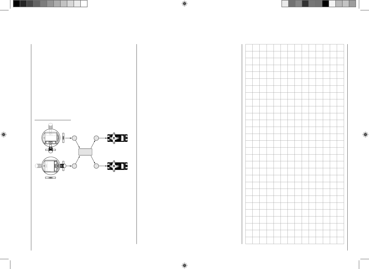
145
Detail program description - Control adjust
What is a mixer?
Basic functionality
With many models, a mix of the model's functions
is often desirable, i. e. coupling aileron to rudder or
coupling two servos together, in cases where rudder
control surfaces with the same functionality are to be
controlled together using a single servo. In all cases,
the signal fl ow at the "output" of the control function on
the transmitter control side "branches" – i. e. also "after"
transmitter control options such as e. g. "Dual Rate /
Expo", "Control adjust", "Channel 1 curve", etc. – in
order for the signal to have its predefi ned effect on
the "input" of a different control channel and thus on a
further receiver output.
Example: V-tail mixer
33
4
Servo 4,8 V
C 577
Best.-Nr. 4101
Servo 4,8 V
C 577
Best.-Nr. 4101
4
V-tail mixer
Control function inputs
Control channels
(receiver outputs)
Elevator stick
Rudder stick
Right rudder / elevator
Left rudder / elevator
Rudder
Elevator
Elevator
Rudder
Rudder
Elevator
The mc-32 HoTT transmitter software contains a
large number of pre-programmed coupling functions as
standard, which are designed to mix together two (or
more) control channels. Accordingly, the mixer named in
the example just above can be activated in the "Tail" line
of the "Model type" menu by selecting "V-tail".
In addition, for each model memory in the fi xed-wing
and heli programs, the software makes available a total
of eight freely programmable linear mixers, four freely
programmable curve mixers and four dual mixers.
Also ensure you read the general remarks on "free
mixers" in this handbook (p. 180).
146 Detail program description - Control adjust
"MIX-only channel" (see page 193) and use it for
another purpose with the help of a "free mixer" (see
page 190).
If you set "2AIL" on the "• Model type" menu (page
82), then the fl ight phase-dependent fl ap functionality
can be achieved by making appropriate offset
settings for input 5 on the "Control adjust" menu
(page 96).
For almost any menu option, you have the option •
of checking your settings by switching to the servo
display screen, which is accessed by simultaneously
tapping the arrow keys ef on the left touch pad.
Caution:
The vertical lines on the "Servo display" move in
the same direction for ailerons and in the opposite
direction for fl aps.
Note that if two fl ap servos have been selected, •
any transmitter control assigned to input 7 will be
decoupled in the software in order to avoid errors in
operating the fl aps. The same applies to input 10 and
the selection "2AIL 4FL".
A range of options are available for positioning fl aps. •
You can …
a) … simply accept one position per fl ight phase, by
setting only the corresponding trim values.
b) … vary the fl aps positioned as at a) by using any
transmitter control, assigned to "Input 6" on the
"Control adjust" menu (page 96) – possibly also
made fl ight phase-dependent by selecting "PH" in
the "Type" column. Preferably, this should be one
of the CTRL 6 … 8 proportional rotary controls.
The selected transmitter control directly controls
the two fl ap servos located on receiver outputs 6
and 7 and, as required, also the two FL2 servos
then the fl ight phase name, e. g. "Normal", will appear on
the lower edge of the display:
Aile.diff.
Brake settings
0%
AI 0%
WING MIXERS
EL AI 0%0%
–––
–––
RU
Normal
All options can then also be programmed specifi c to a
fl ight phase.
Comments:
Using the menu "• Model type" (page 82), control
of the airbrake mixers can be reprogrammed from
control input 1 to 7 or 8 to 9, and the associated
offset point can also be set.
If you wish to set up a "butterfl y" system, with the •
ailerons raised and the fl
aps (if present) lowered, this
is achieved by entering the appropriate settings on
the "Butterfl y" line on the "Brake settings" sub-menu.
If you would like to alternate between the C1 stick •
controlling an electric drive system and a butterfl y
system, then you can use the options in the "Motor"
column on the "Phase settings" menu – see the
example on page 248.
You can also use the opportunity to set switch times •
for a "soft" transition from fl ight phase to fl ight phase
on the "Phase settings" menu (see page 128).
If your model features multiple wing fl aps and a •
"crow / butterfl y system" (see below), but without
additional airbrakes, then you can separate output
1 (usually freed up by the above system) from
control function input 1 (throttle/brake stick) on the
Wing mixers
Calibrating the wing fl ap system
Within the menu tree of the menu …
Free mixers
MIX active/phase
Fl. phase timers
Wing mixers
MIX-only channel
Dual mixer
… the sub-menus and options available depend entirely
on the number of aileron and fl ap servos set up on the
"Model type" menu (page 82) …
Tail type
Motor at C1
Normal
None
Aile/flaps 2AIL
M O D E L T Y P E
Brake Off 1In
+100%
SEL
… which means that the only settings listed are the
ones that can actually be confi gured. This not only
makes the menu more compact but also avoids potential
programming errors.
With a preset of e. g. "2AIL" (no fl aps), the "Wing
mixers" menu will be shown as follows:
Aile.diff.
Brake settings
0%
AI 0%
WING MIXERS
EL AI 0%0%
–––
–––
RU
normal
If you have confi gured several fl ight phases on the
menus "Phase settings" (page 128) and "Phase
assignment" (page 134), and assigned these names,
147
Detail program description - Control adjust
connected to outputs 9 and 10 – assuming that
corresponding fl aps have been specifi ed on the
"Aile/fl aps" line on the "Model type" menu. This
transmitter control indirectly controls the fl ap
position of the ailerons via the percentage value
entered in the "Ail" (and "Ail2") column on the
"FLAP" line of the multi-fl ap menu.
To be able to provide more fi ne-grained control of
fl ap positions, however, you should reduce travel
to about 25% on the "Input 6" line of the "Control
adjust" menu.
c) … alternatively, you can also leave the default
entry of "0%" in the "Ail" (and "Ail2") column on
the "FLAP" line of the multi-fl ap menu, and use
the "Control adjust" menu to assign both input
6 and input 5 to the same transmitter control. You
can then set the degree to which both fl ap pairs
are affected – optionally making this fl ight phase-
dependent by selecting "PH" in the "Type" column
– with the respective travel adjustment.
Basic programming procedure
Select the desired line by using the arrow keys 1. cd
on the left or right touch pad.
Depending on the line selected, the bottom line of the
display will either show the "Next page" icon ( ) or
a switch icon.
Depending on the line selected, you will either switch 2.
to the next page – on which you carry out the same
procedure as below – or the desired value fi eld is
activated by tapping the center SET key on the right
touch pad.
Use the arrow keys to set the mixer ratio or degree of 3.
differential.
Accordingly, specify the input 1, 7, 8 or 9 and the offset
corresponding to your customary piloting in the "Brake
offset" line on the "Model type" menu – see page 82.
When selecting "input 1", please note also that you
may need to specify your desired "Throttle min" position
"forward/back" before establishing the offset point in the
"Motor at C1" line.
Note:
If the offset is not set right at the end of the transmitter
travel, the rest of the travel is a "dead zone", i. e. the
transmitter control does not infl uence any mixers on the
"Brake settings" sub-menu. Otherwise, the mixer travel is
expanded back to 100% automatically.
All other mixers on the "Wing mixers" menu have their
neutral point with the control at its center, i. e. they have
no effect at this control position. The value set is mixed
in at full travel.
To confi gure symmetrical mixer values, move the
transmitter control or joystick to its center position, so
that the marker frame surrounds both value fi elds. To
confi gure asymmetric values, move the transmitter
control/joystick to the corresponding side.
Negative and positive parameter values are possible,
in order to be able to adjust the respective function to
the direction of servo rotation or fl ap orientation.
Tapping the 4. cd or ef keys on the right touch
pad at the same time (CLEAR) will reset the values
entered in the currently active (highlighted) fi eld to
the default value.
Complete your input by tapping the center 5. ESC key
on the left touch pad or the center SET key on the
right touch pad.
Assigning switches
The wing mixers "AI ¼ RU" and "FL ¼ EL" can be
optionally switched on and off by using a switch or
an expanded switch. Accordingly, when selecting the
respective line, the familiar switch icon ( ) appears on
the lower edge of the screen.
Switching delays
The delay time or switch time confi gured on the menu
"Phase settings" (page 128) for the respective fl ight
phase also affects all wing mixers and thus avoids
abrupt changes to fl ap confi gurations when switching
between the fl ight phases.
Mixer neutral points (offset)
For all mixers on the "Brake settings" submenu, the
"brake offset" to be set on the "Model type" menu is to
be confi gured to the transmitter control position at which
the airbrakes are retracted.
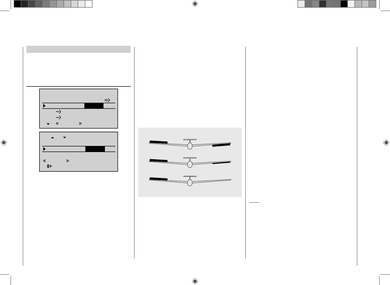
148 Detail program description - Control adjust
defl ection also generates drag and therefore further
reduces the aircraft's effi ciency.
If, on the other hand, a differential is applied to the
aileron orientations, by giving the aileron oriented
downwards a smaller defl ection than the aileron
oriented upwards, the (undesirable) adverse yaw can
be reduced – and possibly entirely negated. However,
the basic precondition for this is that each aileron must
have its own servo present, which can therefore also
be embedded straight into the aerofoils. In addition, the
shorter linkage paths produce an additional benefi t:
reproducible aileron confi gurations that also exhibit less
"play".
0% (normal)
50% (differential)
100% (split)
Unlike mechanical solutions, which not only commonly
need to be designed and built in when constructing
the model but also produce a slightly increased "play"
in the control system for strong differentials, the
transmitter-based differential typically used today offers
considerable benefi ts.
The degree of differential can be changed at any
time, for example, and, in extreme circumstances, the
downward defl ection of an aileron – in what is termed
a "split" position – can be suppressed entirely. This
approach not only reduces or even suppresses "adverse
yaw", but can, in certain circumstances, even generate
a positive yaw: in such cases, an aileron command will
generate a yaw about the vertical axis in the direction
of the turn. For large glider models in particular, this
approach lets such aircraft fl y "clean" turns using just
the ailerons, which is not otherwise possible unaided.
The adjustment range of -100% to +100% makes it
possible to set a differential appropriate for each side,
regardless of the direction of rotation of the aileron
servos. While "0%" corresponds to a normal linkage, i. e.
no differential, "-100%" or "+100%" represents the "split"
function.
For aerobatic fl ying, low absolute values are required to
ensure the model rotates exactly along its longitudinal
axis when an aileron command is given. Values near
to the center (-50% or +50%) are typical for facilitating
turns in thermals. The split setting (-100%, +100%) is
popular with slope fl yers, where ailerons alone are often
used for turning the model.
If you tap the cd or ef keys on the right touch
pad (CLEAR) at the same time, this will reset values
changed in the active (highlighted) fi eld back to 0%.
Note:
Negative values are not usually necessary if channels
are assigned properly.
Mixer functions
The individual options on the "Wing mixers" menu
option are discussed below, separately for single-, dual-
and multi-fl ap models. Before we start, a number of
remarks on the differentials for ailerons and fl aps:
Aile. diff. or Diff. ( Aileron differential)
0%
0%0%
–––
–––
Normal
0%
Aile.diff.
Brake settings
AI
WING MIXERS
EL AI
RU
0%
fl.pos
AILE
Normal
Diff.
AiI-tr
AI +100%
+100%
0%
For aerodynamic reasons, the drag generated on
an aileron oriented downwards is greater than that
generated by the same aileron when it is oriented
upwards by the same amount. One effect of this unequal
distribution of drag produces is a yawing motion around
the vertical axis and, accordingly, a "turning away"
from the intended direction of fl ight, which is why this
undesirable side effect is also termed "adverse yaw".
This effect is naturally greater on the comparably long
aerofoils possessed by model gliders, compared to e. g.
powered aircraft models, which generally have relatively
short moment arms. For the former, it must normally
be compensated for by making a simultaneous rudder
defl ection in the opposite direction. However, this rudder
149
Detail program description - Control adjust
Diff. (camber-changing fl ap differential)
0%
fl.pos
FLAP
Normal
Diff.
Ail-tr
AI 0%
0%
0%
0%
FLAP2
0%
0%
0%
fl.pos
Normal
Diff.
Ail-tr
AI
In the "cAId" line on the multi-fl ap menu, you can set
the extent to which the fl aps act as ailerons and follow the
aileron joystick; the value is entered as a percentage. The
fl aps differential – to be set on the line "Diff." (two lines
below) – works in a similar way to the aileron differential,
i.e. where an aileron command acts on the fl aps, the
respective defl ection downwards can be reduced.
The adjustment range of -100% to +100% makes it possible
to set a differential appropriate for each side, regardless
of the direction of rotation of the servos. A value of 0% is
equal to normal linkage, i. e. the servo travel downwards is
the same as the travel upwards. A value of -100% to +100%
means that travel downwards will be reduced to zero for
aileron commands affecting the fl aps ("split" mode).
If you tap the cd or ef keys on the right touch
pad (CLEAR) at the same time, this will reset values
changed in the active (highlighted) fi eld back to 0%.
Note:
Negative values are not usually necessary if channels
are assigned properly.
exception of a "pointer" to the "Elevat curve" sub-menu.
Accordingly, we proceed immediately further from here
by once again tapping the center SET key on the right
touch pad:
Input
Output
Point ?
–100%
0%
0%
Brake
normal
Ele
Curve off
Normal
If required, i. e. if you have the feeling that you will need
to set pitch trim compensation when the airbrakes are
extended, you can program an appropriate automatic
mixer affecting the elevator at this point.
For detailed instructions on setting a curve mixer, please
refer to menu option "Channel 1 curve" (page 116
onwards).
Aileron ¼ Rudder
Brake settings
AI 0%
WING MIXERS
–––
RU
Normal
Here, you can set the degree to which the rudder follows
commands acting on ailerons. This is used in particular
in connection with aileron differential to suppress
adverse yaw and thus make it easier to fl y "clean"
curves. You can of course still issue separate commands
to the rudder.
The adjustment range of ±150% lets you set the
Model type: "1AIL"
If you have entered "1AIL" for the "Aile/fl aps" line on the
"Model type" menu (page 82 ), then the "Wing mixers
menu" on your transmitter will match the following
screen image:
Brake settings
AI 0%
WING MIXERS
–––
RU
Normal
From the fi rst line on this display screen, you can switch
to the sub-menu by briefl y tapping the center SET key
on the right touch pad …
Brake settings
Note:
The "Brake settings" menu is switched "off" if you
entered "Motor on C1 forward / back" on the "Model
type" menu (see page 82), and entered "Yes" for the
currently active fl ight phase in the "Motor" column of the
"Phase settings" menu (see page 128). Switch the fl ight
phase if required:
Elevat curve
BRAKE SETTINGS
normal
Normal
Since you cannot set up a butterfl y or aileron differential
in a model with only a single aileron servo, this
menu offers no further confi guration options with the
150 Detail program description - Control adjust
Model type: "1AIL 1FL"
If you have entered "1AIL 1FL" for the "Aile/fl aps"
line on the "Model type" menu (page 82), then the
"Wing mixers menu" on your transmitter will match the
following screen image:
Brake settings
AI 0%
WING MIXERS
EL FL 0%
0%
–––
–––
RU
Normal
FL EL 0%
0% –––
From the fi rst line on this display screen, you can switch
to the sub-menu by briefl y tapping the center SET key
on the right touch pad …
Brake settings
Note:
The "Brake settings" menu is switched "off" if you
entered "Motor on C1 forward / back" on the "Model
type" menu (see page 82), and entered "Yes" for the
currently active fl ight phase in the "Motor" column of the
"Phase settings" menu (see page 128). Switch the fl ight
phase if required:
Elevat curve
BRAKE SETTINGS
Crow
Normal
0%
FLAP
Appropriate to the model type selected, you can now
enter a suitable value in the "Crow" line to lower the fl ap
when you activate the brake control – which is typically
the C1 joystick.
To confi gure the setting, fi rst position the brake control in
the brake position at full travel (i.e. its end-point). Then,
briefl y tap the center SET key on the right touch pad and
enter a suitable value using the arrow keys on the left or
right touch pad. To ensure a suffi ciently strong braking
effect, note that you should try to lower the fl ap as low
as is mechanically possible.
From the second line on this display screen, you can
switch to the sub-menu "Elevat curve" by briefl y tapping
the center SET key on the right touch pad:
Input
Output
Point ?
–100%
0%
0%
Brake
normal
Ele
Curve off
Normal
If required, i. e. if you have the feeling that you will need
to set pitch trim compensation when the airbrakes are
extended, you can program an appropriate automatic
mixer affecting the elevator at this point.
For detailed instructions on setting a curve mixer, please
refer to menu option "Channel 1 curve" (page 116
onwards).
Aileron ¼ Rudder
Brake settings
AI 0%
WING MIXERS
EL FL 0%
0%
–––
–––
RU
Normal
FL EL 0%
0% –––
direction of defl ection as appropriate. Optionally, this
mixer can be activated and deactivated by using one of
the switches that do not reset themselves (SW 2 … 8) or
a control switch. This means you can then also control
the model using only the ailerons or rudder, as required.
Typically, this mixer is set so that the rudder is defl ected
to the same side as the upward-oriented aileron, and
you will fi nd that setting a value of around 50% is usually
highly appropriate.
Settings are always made symmetrically relative to the
neutral point of the aileron joystick.
If you tap the cd or ef keys on the right touch
pad (CLEAR) at the same time, this will reset values
changed in the active (highlighted) fi eld back to 0%.
151
Detail program description - Control adjust
Here, you can set the degree to which the rudder follows
commands acting on ailerons. This is used in particular
in connection with aileron differential to suppress
adverse yaw and thus make it easier to fl y "clean"
curves. You can of course still issue separate commands
to the rudder.
The adjustment range of ± 150% lets you set the
direction of defl ection as appropriate. Optionally, this
mixer can be activated and deactivated by using one of
the switches that do not reset themselves (SW 2 … 8) or
a control switch. This means you can then also control
the model using only the ailerons or rudder, as required.
Typically, this mixer is set so that the rudder is defl ected
to the same side as the upward-oriented aileron, and
you will fi nd that setting a value of around 50% is usually
highly appropriate.
Settings are always made symmetrically relative to the
neutral point of the aileron joystick.
If you tap the cd or ef keys on the right touch
pad (CLEAR) at the same time, this will reset values
changed in the active (highlighted) fi eld back to 0%.
Elevator ¼ fl a p s
Brake settings
AI 0%
WING MIXERS
EL FL 0%
0%
–––
–––
RU
Normal
FL EL 0%
0% –––
To provide support for the elevator for tight turns
and aerobatics, this mixer can be used to make the
fl ap function follow controls sent to the elevator. The
mixer direction chosen must ensure that the fl aps are
defl ected downwards when the elevator is oriented
upwards and vice versa for a downward-oriented
elevator – i.e. in opposite directions. Optionally, this
mixer can be activated and deactivated by using one of
the switches that do not reset themselves (SW 2 … 8) or
a control switch.
To confi gure symmetrical mixer values, move
the elevator joystick to its center position, so that
the marker frame surrounds both value fi elds. To
confi gure asymmetric values, move the joystick to the
corresponding side.
Values in the range -150% to +150 are possible, so as
to adjust the function to the direction of servo rotation or
direction of fl ap defl ection.
If you tap the cd or ef keys on the right touch
pad (CLEAR) at the same time, this will reset values
changed in the active (highlighted) fi eld back to 0%.
The "typical" values confi gured for this mixer are single-
digit or low two-digit values.
Flaps ¼ elevator
Brake settings
AI 0%
WING MIXERS
EL FL 0%
0%
–––
–––
RU
Normal
FL EL 0%
0% –––
This mixer is used to set elevator (pitch-trim)
compensation when a fl ap command is given. This
typically enables you to adjust the model's airspeed
automatically when fl aps are lowered.
If you have used the "Control adjust" menu (page 96)
to assign input 6 a transmitter control or switch –
possibly fl ight phase-dependent – then this also affects
this mixer.
Depending on the position of the fl ap control, either
a symmetrical or asymmetric setting within the range
±150% is possible.
If you tap the cd or ef keys on the right touch
pad (CLEAR) at the same time, this will reset values
changed in the active (highlighted) fi eld back to 0%.
If required, the mixer can be switched on or off by
assigning a switch in the right column.
The values confi gured for this mixer are typically in the
single-digit range.
152 Detail program description - Control adjust
Model type: "2AIL"
If you have entered "2AIL" for the "Aile/fl aps" line on the
"Model type" menu (page 82), then the "Wing mixers
menu" on your transmitter will match the following
screen image:
Aile.diff.
Brake settings
0%
AI 0%
WING MIXERS
EL AI 0%0%
–––
–––
RU
Normal
From the fi rst line on this display screen, you can switch
to the sub-menu by briefl y tapping the center SET key
on the right touch pad …
Brake settings
Note:
The "Brake settings" menu is switched "off" if you
entered "Motor on C1 forward / back" on the "Model
type" menu (see page 82), and entered "Yes" for the
currently active fl ight phase in the "Motor" column of the
"Phase settings" menu (see page 128). Switch the fl ight
phase if required:
Elevat curve
BRAKE SETTINGS
AILE
Crow
D.red
0%
0%
0%
0%
0%
0%
WK WK2
Normal
Depending on the model type selected, you will now
have appropriate confi guration options available in
the lines "Crow" and "D(ifferential) red(uction)" for the
"AILE" column. You should utilize these options by …
… moving the transmitter control for "Brake" •
(see description for "Model type" menu on page
82 – typically the C1 joystick – to its braking end-point.
Then switch to the "Crow" line, briefl y tap the center
SET key on the right touch pad and use the arrow
keys on the left or right touch pad to set a value that
moves the aileron upwards as far as possible to
brake the model, or – if you are using airbrakes as
the main braking system – the aileron should be set
to elevate only minimally to provide an extra braking
effect.
Note:
To reliably prevent the servos mechanically striking
their end-stops – which draws a heavy current – you
can set an appropriate limit value in the "– lim +"
column of the "Servo adjustments" menu (page 90).
… then, fi nally, moving to the "D. red" line and setting •
a % value that is greater than or equal to the "Aile.
diff." value that you set (or have yet to set) on the
display page "before" this one.
In this way, you can suppress the aileron differential
when braking, thus ensuring that you can count on
suffi cient aileron response despite your ailerons
being defl ected upwards.
From the lowest line, "Elevat. curve", you can switch to
setting the "Elevat. curve" mixer by briefl y tapping the
center SET key on the right touch pad:
Input
Output
Point ?
–100%
0%
0%
Brake
normal
Ele
Curve off
Normal
If required, i. e. if you have the feeling that you will need
to set pitch trim compensation when the airbrakes are
extended, you can program an appropriate automatic
mixer affecting the elevator at this point.
For detailed instructions on setting a curve mixer, please
refer to menu option "Channel 1 curve" (page 116
onwards).
Aileron differential
Aile.diff.
Brake settings
0%
AI 0%
WING MIXERS
EL AI 0%0%
–––
–––
RU
Normal
The adjustment range of ±100% makes it possible to
set the correct direction of differential, regardless of the
direction of rotation of the aileron servos. While "0%"
corresponds to a normal linkage, i. e. no differential on
the transmitter, "-100%" or "+100%" represents the
"split" function.
For aerobatic fl ying, low absolute values are required to
ensure the model rotates exactly along its longitudinal
axis when an aileron command is given. Values near
to the center (-50% or +50%) are typical for facilitating
turns in thermals. The split setting (-100%, +100%) is
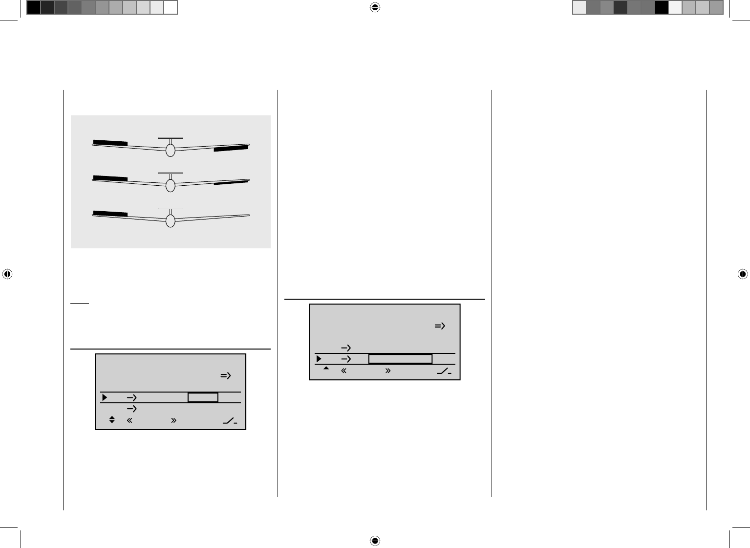
153
Detail program description - Control adjust
popular with slope fl yers, where ailerons alone are often
used for turning the model.
0% (normal)
50% (differential)
100% (split)
If you tap the cd or ef keys on the right touch
pad (CLEAR) at the same time, this will reset values
changed in the active (highlighted) fi eld back to 0%.
Note:
Negative values are not usually necessary if channels
are assigned properly.
Aileron ¼ rudder
Aile.diff.
Brake settings
0%
AI 0%
WING MIXERS
EL AI 0%0%
–––
–––
RU
Normal
Here, you can set the degree to which the rudder follows
commands acting on ailerons. This is used in particular
in connection with aileron differential to suppress
adverse yaw and thus make it easier to fl y "clean"
curves. You can of course still issue separate commands
to the rudder.
The adjustment range of ± 150% lets you set the
direction of defl ection as appropriate. Optionally, this
mixer can be activated and deactivated by using one of
the switches that do not reset themselves (SW 2 … 8) or
a control switch. This means you can then also control
the model using only the ailerons or rudder, as required.
Typically, this mixer is set so that the rudder is defl ected
to the same side as the upward-oriented aileron, and
you will fi nd that setting a value of around 50% is usually
highly appropriate.
Settings are always made symmetrically relative to the
neutral point of the aileron joystick.
If you tap the cd or ef keys on the right touch
pad (CLEAR) at the same time, this will reset values
changed in the active (highlighted) fi eld back to 0%.
Elevator ¼ aileron
Aile.diff.
Brake settings
0%
AI 0%
WING MIXERS
EL AI 0%0%
–––
–––
RU
Normal
To provide support for the elevator for tight turns
and aerobatics, this mixer can be used to make the
aileron function follow controls sent to the elevator. The
mixer direction chosen must ensure that the fl aps are
defl ected downwards when the elevator is oriented
upwards and vice versa for a downward-oriented
elevator – i.e. in opposite directions. Optionally, this
mixer can be activated and deactivated by using one of
the switches that do not reset themselves (SW 2 … 8) or
a control switch.
To confi gure symmetrical mixer values, move the
elevator joystick to its center position, so that the
marker frame surrounds both value fi elds. To confi gure
asymmetric values, move the transmitter control to the
corresponding side.
Values in the range -150% to +150 are possible, so as
to adjust the function to the direction of servo rotation or
direction of aileron defl ection.
If you tap the cd or ef keys on the right touch
pad (CLEAR) at the same time, this will reset values
changed in the active (highlighted) fi eld back to 0%.
The "usual" values for this mixer are in the low two-digit
range.
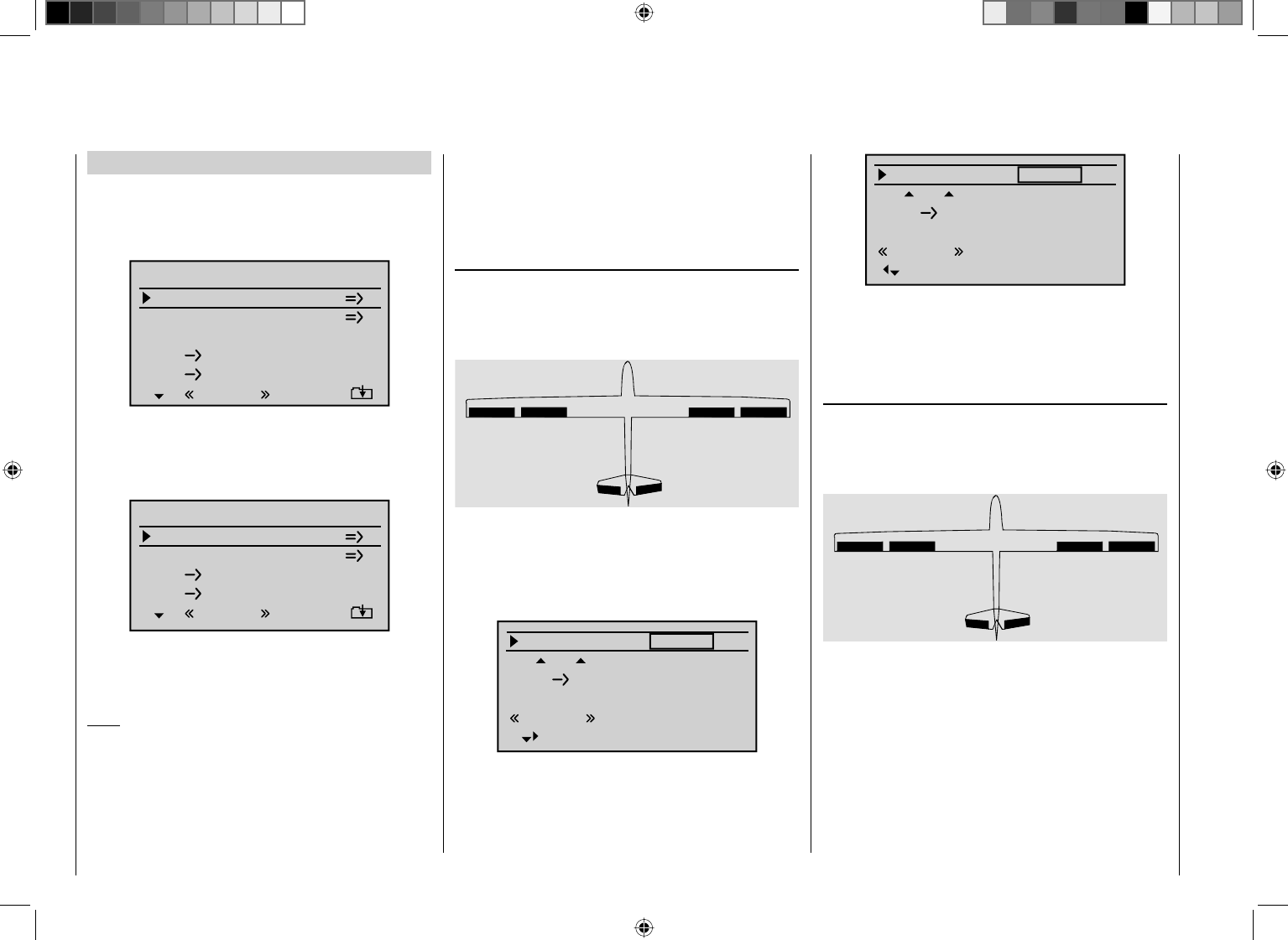
154 Detail program description - Control adjust
Model type: "2/4AIL 1/2/4FL"
If you have entered "2AIL 1FL" for the "Aile/fl aps"
line on the "Model type" menu (page 82), then the
"Wing mixers menu" on your transmitter will match the
following screen image:
Aile.diff.
Brake settings
0%
AI 0%
WING MIXERS
FL EL 0%0%
–––
–––
RU
Multi-flap menu
Normal
If, on the other hand, you have entered "2/4AIL
1/2/4FL" for the "Aile/fl aps" line on the "Model type"
menu (page 82), then the "Wing mixers menu" on your
transmitter will show the following:
0%
0%0%
–––
–––
Brake settings
AI
WING MIXERS
FL EL
RU
Multi-flap menu
Normal
Regardless of the combination of aileron and fl ap servos
you choose, all of the parameters available can be
adjusted separately for each fl ight phase.
Note:
For almost any menu option, you have the option of
checking your settings by switching to the servo display
screen, which is accessed by simultaneously tapping
the arrow keys ef on the left touch pad. If you do, note
however that the vertical lines on the "Servo display"
move in the same direction for ailerons and in the
opposite direction for fl aps.
Before we address the details of this menu we would
like to provide a brief explanation of the different display
modes for the multi-flap menu:
Model type: "2 AIL 1 FL"
If you connect the servos to the receiver as described
on page 57 and select them appropriately on the "Model
type" menu (see page 82), then the abbreviations "AI"
and "FL" refer to the following fl aps:
AI
left
FL FL AI
right
Since the options available on the wing mixer menu
and its sub-menus vary according to the number of fl ap
servos specifi ed on the "Model type" menu (page 82),
the list contains only the set-up options that are possible
for your model configuration.
FL
0%
0%
fl.pos
EL FL 0%0%
0%
AILE
Normal
Accordingly, with values preset to "2AIL 1FL", the
options to set aileron functions for fl aps will be hidden
and it will be possible to move only one column to the
right, into the column "FLAP":
FL +100%
fl.pos
EL FL 0%0%
+100%
FLAP
Normal
0%
In addition, the settings for "Aile(ron) diff(erential)" are
not found on the "multi-fl ap menu", as with "2AIL 2/4FL",
but one level higher in the "Wing mixers" menu – see the
screen-shot at top left.
Model type: "2AIL 2FL"
If you connect the servos to the receiver as described
on page 57 and select them appropriately on the "Model
type menu (see page 82), then the abbreviations "AI"
and "FL" refer to the following fl aps:
AI
left
FL
left
FL
right
AI
right
Since the options available on the "wing mixer menu"
and its sub-menus vary according to the number of fl ap
servos specifi ed on the "Model type" menu (page 82),
the list contains only the set-up options that are possible
for your model configuration.
This means that if values are preset to "2AIL 2FL", then
all confi guration options for the aileron pair …
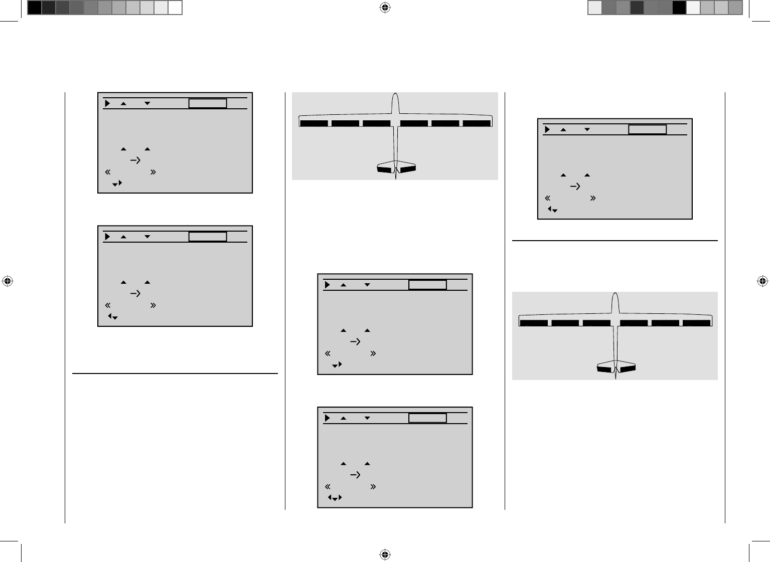
155
Detail program description - Control adjust
FL
0%
0%
fl.pos
EL FL 0%0%
0%
AILE
Normal
Diff. 0%
Ail-tr
AI +100%
+100%
… are shown, and – one "step" to the right – all options
for the fl ap pair as well:
0%
+100%
0%0%
+100%
FLAP
0%
0%
0%
FL
fl.pos
EL FL
Normal
Diff.
Ail-tr
AI
Moving one further column to the right, however – to the
"FLAP2" column – is not possible.
Model type: "2AIL 4FL"
If you connect the servos to the receiver as described
on page 57 and select them appropriately on the "Model
type" menu (see page 82), then the abbreviations "AI",
"FL" and "FL2" refer to the following fl aps:
AI
left
FL
left
FL2
left
FL2
right
FL
right
AI
right
Since the options available on the "wing mixer menu"
and its sub-menus vary according to the number of fl ap
servos specifi ed on the "Model type" menu (page 82 ),
the list contains only the set-up options that are possible
for your model configuration.
This means that if values are preset to "2AIL 4FL", then
all confi guration options for the aileron pair …
FL
0%
0%
fl.pos
EL FL 0%0%
0%
AILE
Normal
Diff. 0%
Ail-tr
AI +100%
+100%
… are shown, and – one "step" to the right – all options
for the fi rst fl ap pair …
0%
+100%
0%0%
+100%
FLAP
0%
0%
0%
FL
fl.pos
EL FL
Normal
Diff.
Ail-tr
AI
… are shown, and – one further "step" to the right – all
options for the second fl ap pair as well:
0%
+100%
0%0%
+100%
FLAP2
0%
0%
0%
FL
fl.pos
EL FL
Normal
Diff.
Ail-tr
AI
Model type: "4AIL 2FL"
If you connect the servos to the receiver as described
on page 57 and select them appropriately on the "Model
type" menu (see page 82), then the abbreviations "AI",
"AI2" and "FL" refer to the following fl aps:
AI
left
AI2
left
FL
left
FL
right
AI2
right
AI
right
Since the options available on the "wing mixer menu"
and its sub-menus vary according to the number of fl ap
servos specifi ed on the "Model type" menu (page 82 ),
the list contains only the set-up options that are possible
for your model configuration.
This means that if values are preset to "4AIL 2FL", then
all confi guration options for the fi rst aileron pair …
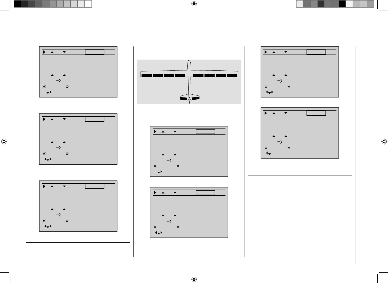
156 Detail program description - Control adjust
FL
0%
0%
fl.pos
EL FL 0%0%
0%
AILE
Normal
Diff. 0%
Ail-tr
AI +100%
+100%
… are shown, and – one "step" to the right – all options
for the second aileron pair …
0%
0%
0%0%
0%
AILE2
0%
+100%
+100%
FL
fl.pos
EL FL
Normal
Diff.
Ail-tr
AI
… are shown, and – one further "step" to the right – all
options for the fl ap pair as well:
0%
+100%
0%0%
+100%
FLAP
0%
0%
0%
FL
fl.pos
EL FL
Normal
Diff.
Ail-tr
AI
Model type: "4AIL 4FL"
If you connect the servos to the receiver as described
on page 57 and select them appropriately on the "Model
type" menu (see page 82), then the abbreviations "AI",
"AI2", "FL" and "FL2" refer to the following fl aps:
AI
left
AI2
left
FL
left
FL2
left
FL2
right
FL
right
AI2
right
AI
right
Since selecting "4AIL 4FL" means choosing the
maximum number of control surface servos, the
columns "AILE" …
FL
0%
0%
fl.pos
EL FL 0%0%
0%
AILE
Normal
Diff. 0%
Ail-tr
AI +100%
+100%
… and "AILE2" …
0%
0%
0%0%
0%
AILE2
0%
+100%
+100%
FL
fl.pos
EL FL
Normal
Diff.
Ail-tr
AI
… are supplemented by the columns "FLAP" …
0%
+100%
0%0%
+100%
FLAP
0%
0%
0%
FL
fl.pos
EL FL
Normal
Diff.
Ail-tr
AI
… and "FLAP2":
0%
+100%
0%0%
+100%
FLAP2
0%
0%
0%
FL
fl.pos
EL FL
Normal
Diff.
Ail-tr
AI
Delta/fl ying wing type models with more than two
wing fl aps
If you have selected the "Delta/fl " tail type and selected
the number of wing fl aps in the "Aile/fl aps" line on the
"Model type" menu (following the instructions given
in that section), then the two ailerons will normally not
move when you move the elevator joystick – and the
same will be true for the inner fl aps (FL) and FL2 (if
present). The reason for this is the default mixer ratio of
0% for all wing fl aps, set for the "EL ¼ FL" mixer that is
to be found on the multi-fl ap menu:
157
Detail program description - Control adjust
0%
0%
0%0%
0%
AILE
0%
+100%
+100%
FL
fl.pos
EL FL
Normal
Diff.
Ail-tr
AI
Accordingly, you must fi rst specify your desired elevator
control on the "EL ¼ FL" line. Take care to ensure that
up/down activation occurs in the right sequence.
Note:
The "Brake settings" sub-menu (see next double page)
is also suitable for setting up the butterfl y (crow) function
with delta and fl ying wing models. In fi ne-tuning the
defl ection of the fl ap pairs AIL, FL and (if present) FL2,
however, ensure that the moments created by one pair
of fl aps compensate the moments created by the other
pair of fl aps in each case. For example: the "up" effect of
ailerons when defl ected up should be compensated by a
"down" effect from fl aps when they are lowered.
Multi-fl ap menu
Important notice:
Depending on the fl ap pairs specifi ed in the "Model
type" menu, this menu will present the column "AILE2"
and/or the columns "FLAP" and "FLAP2" in addition
to the "AILE" column. Since both the columns "AILE"
and "AILE2" and the columns "FLAP" and "FLAP2" are
identical except for the label shown at the bottom right,
further display of the columns "AILE2" and "FLAP2" is
avoided below for reasons of saving space.
VAIW (Aileron ¼ fl aps)
(Not shown for "2AIL 1FL".)
0%
AILE
0%
+100%
+100%
fl.pos
Normal
Diff.
Ail-tr
AI
0%
FLAP
0%
0%
0%
fl.pos
Normal
Diff.
Ail-tr
AI
In the line "VAIW"you can set the percentage extent to
which the wing fl ap pair "FLAP" (and, if present, "FL2")
follow when an aileron command is given (the value
can be entered separately for each fl ight phase). (In the
"AILE" column it is also possible to adjust the deflection
of the aileron pair, if required.) Normally, however, the
fl aps should follow the ailerons with less of a defl ection,
i. e. the mixer ratio should be smaller than 100%.
The adjustment range of -150% to +150% means the
direction of defl ection can be adjusted, depending on
the direction of rotation of the servos, to suit the ailerons.
If you tap the cd or ef keys on the right touch
pad (CLEAR) at the same time, this will reset values
changed in the active (highlighted) fi eld back to the
default value (see screen image).
Ail-tr. (aileron trim)
(Not shown for "2AIL 1FL".)
0%
AILE
0%
+100%
+100%
fl.pos
Normal
Diff.
Ail-tr
AI
0%
FLAP
0%
0%
0%
fl.pos
Normal
Diff.
Ail-tr
AI
In this line, you specify the percentage rate with which
aileron trim is to affect "AILE", "FLAP" and – if present
– "FLAP2".
The available range of values is -150% to +150%,
relative to the adjustment range of the trim lever.
If you tap the cd or ef keys on the right touch
pad (CLEAR) at the same time, this will reset values
changed in the active (highlighted) fi eld back to the
default value (see screen image).
Diff. (Differential for aileron function)
(With "2AIL 1FL", found one level higher on the "Wing
mixers" menu – see screen image on previous double
page.)
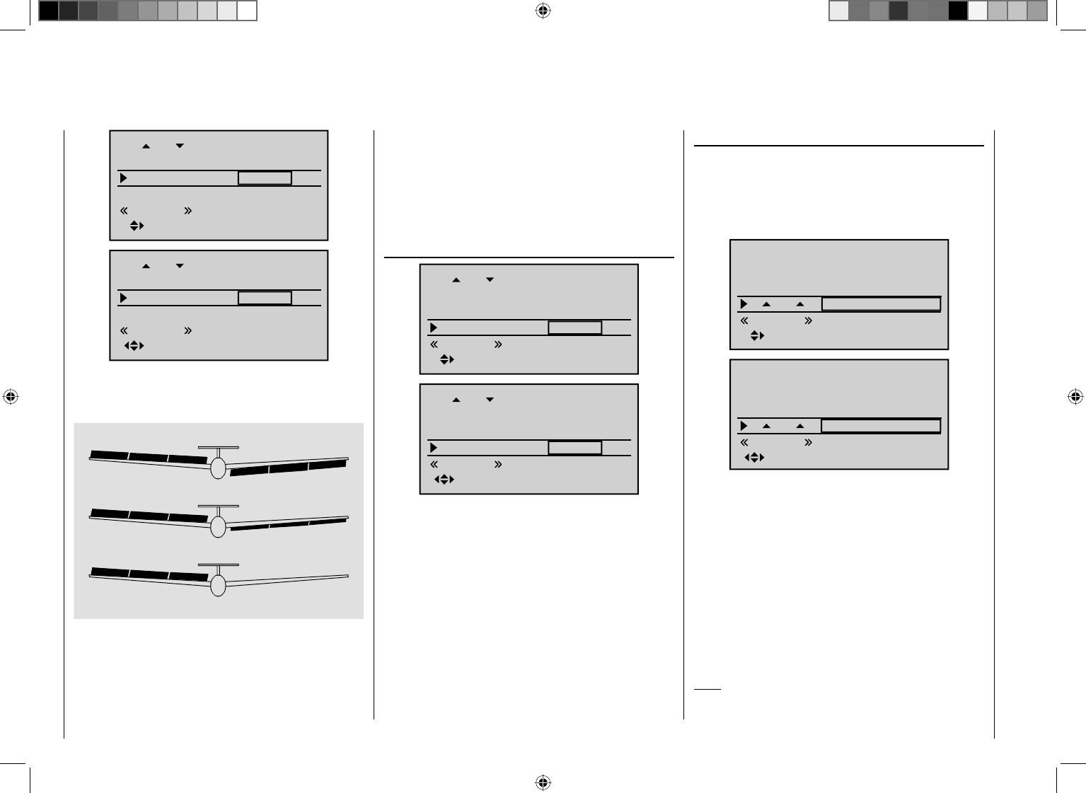
158 Detail program description - Control adjust
0%
AILE
0%
+100%
+100%
fl.pos
Normal
Diff.
Ail-tr
AI
0%
FLAP
0%
0%
0%
fl.pos
Normal
Diff.
Ail-tr
AI
On this line, you set the aileron differential, plus the
differential for the FLAP and FLAP2 wing flaps – if the
latter are being activated as ailerons.
0% (normal)
50% (differential)
100% (split)
AI FL FL2 FL2 FL AI
If you are unsure about the meaning of differential travel,
please read the appropriate explanation at the start of
this section on page 148.
The adjustment range of -100% to +100% makes
it possible to set the correct direction of differential
regardless of the direction of rotation of the aileron and
fl ap servos.
If you tap the cd or ef keys on the right touch
pad (CLEAR) at the same time, this will reset values
changed in the active (highlighted) fi eld back to the
default value (see screen image).
fl .pos (wing fl ap position)
0%
AILE
0%
+100%
+100%
fl.pos
Normal
Diff.
Ail-tr
AI
0%
FLAP
0%
0%
0%
fl.pos
Normal
Diff.
Ail-tr
AI
Here, you set the fl ight phase-specifi c wing fl ap
positions for all of the flaps present on the model in
question. In this way, you can specify the flap positions
that apply to each flight phase.
The adjustment range of -100% to +100% makes it
possible to set the correct direction of travel regardless
of the direction of rotation of the aileron and fl ap servos.
If you tap the cd or ef keys on the right touch
pad (CLEAR) at the same time, this will reset values
changed in the active (highlighted) fi eld back to the
default value (see screen images).
VFLV (Effects of fl ap controls)
In this line, you specify the percentage rate with which
the settings for input 6 (as made on the "Control
adjust" menu, page96, and potentially dependent on
fl ight phase) will affect the wing fl ap positions of the
aileron and camber-changing fl aps.
0%
0%
0%
AILE
0%
+100%
FL
fl.pos
Normal
Diff.
Ail-tr
0%
+100%
+100%
FLAP
0%
0%
FL
fl.pos
Normal
Diff.
Ail-tr
For each fl ap pair, you can defi ne either a symmetrical
or an asymmetric effect. Position the transmitter control
accordingly – either centrally or to the relevant side.
If you leave (or have left) each travel adjustment at
+100% on the "Control adjust" menu (page 96), then
values between 5% and 20% should generally be
suffi cient.
If you tap the cd or ef keys on the right touch
pad (CLEAR) at the same time, this will reset values
changed in the active (highlighted) fi eld back to the
default value (see screen images).
Note:
By default, NO transmitter control is assigned to input 6
159
Detail program description - Control adjust
on the "Control adjust" menu. However, you can assign
a transmitter control or switch to this input at any time
– also in a fl ight phase-dependent way – thus enabling
different fl ap settings within a fl ight phase; see also
example 2 on page 260.
EL ¼ FL (Elevator ¼ fl aps)
To provide support for the elevator for tights turns
and aerobatics, this mixer can be used to make the
fl ap function follow controls sent to the elevator. The
mixer direction chosen must ensure that the fl aps are
defl ected downwards when the elevator is oriented
upwards and vice versa for a downward-oriented
elevator – i.e. in opposite directions.
For each fl ap pair, you can defi ne either a symmetrical
or an asymmetric effect. Position the transmitter control
accordingly – either centrally or to the relevant side.
Values in the range -150% to +150% are possible:
0%
0%
0%0%
0%
AILE
0%
FL
fl.pos
EL FL
Normal
Diff.
0%
+100%
0%0%
+100%
FLAP
0%
FL
fl.pos
EL FL
Normal
Diff.
If you tap the cd or ef keys on the right touch
pad (CLEAR) at the same time, this will reset values
changed in the active (highlighted) fi eld back to the
default value (see screen images).
The "usual" values for this mixer are in the low two-digit
range.
Important general notice:
Do not let control surfaces and servos strike their
mechanical end-stops when large defl ections
are set! This is especially relevant in relation to
the functions "VAIW", "VFLW" and possibly
"VFL2W". Use the "- lim +" option (travel limit)
available on the "Servo adjustments" menu
(page 90), as required.
Brake settings
Notes:
The "Brake settings" menu is switched "off" if you •
entered "Motor on C1 forward / back" on the "Model
type" menu (see page 82), and entered "Yes" for the
currently active fl ight phase in the "Motor" column of
the "Phase settings" menu (see page 128). Switch
the fl ight phase if required:
The "brake mixers" described below can also – •
and should also – be confi gured to be specifi c to
individual fl ight phases.
C r o w
Elevat curve
BRAKE SETTINGS
AILE
Crow
D.red
0%
0%
0%
0%
0%
0%
FLAP FLAP2
Normal
The "Crow" mixer function is actuated by control function
1, 7, 8 or 9, depending on the input that you have
assigned on the "Brake Off" line on the "Model type"
menu (see page 82).
Tail type
Motor at C1
Normal
None
Aile/flaps 1AIL
M O D E L T Y P E
Brake off +90%
SELSTO
In 1
Note:
On the "Model type" menu (see page 82), you should
also defi ne the offset, i. e. the direction of operation.
The offset should be set to about +90% of stick travel
(if the C1 stick is used, this is generally located at the
forward position of the stick). To extend the fl aps, the
stick must therefore be moved back towards the pilot.
The remaining joystick travel of around 10% then has no
effect, although it is not "lost", since the control travel is
automatically expanded back to 100%.
Use the select fi elds for the AILE, FLAP and – if present
– FL2 columns to defi ne the extent and direction to
which the corresponding pairs of fl aps are to follow
when the airbrake control (control function 1, 7, 8 or
9) is operated. If the model does not feature separate
airbrakes, leave the corresponding receiver output free
or use the "MIX-only channel" menu to set this to "MIX-
only", to be able to use it elsewhere.
Values in the range -150% to +150% are possible.
If you tap the cd or ef keys on the right touch
pad (CLEAR) at the same time, this will reset values
changed in the active (highlighted) fi eld back to the
default value (see screen image).
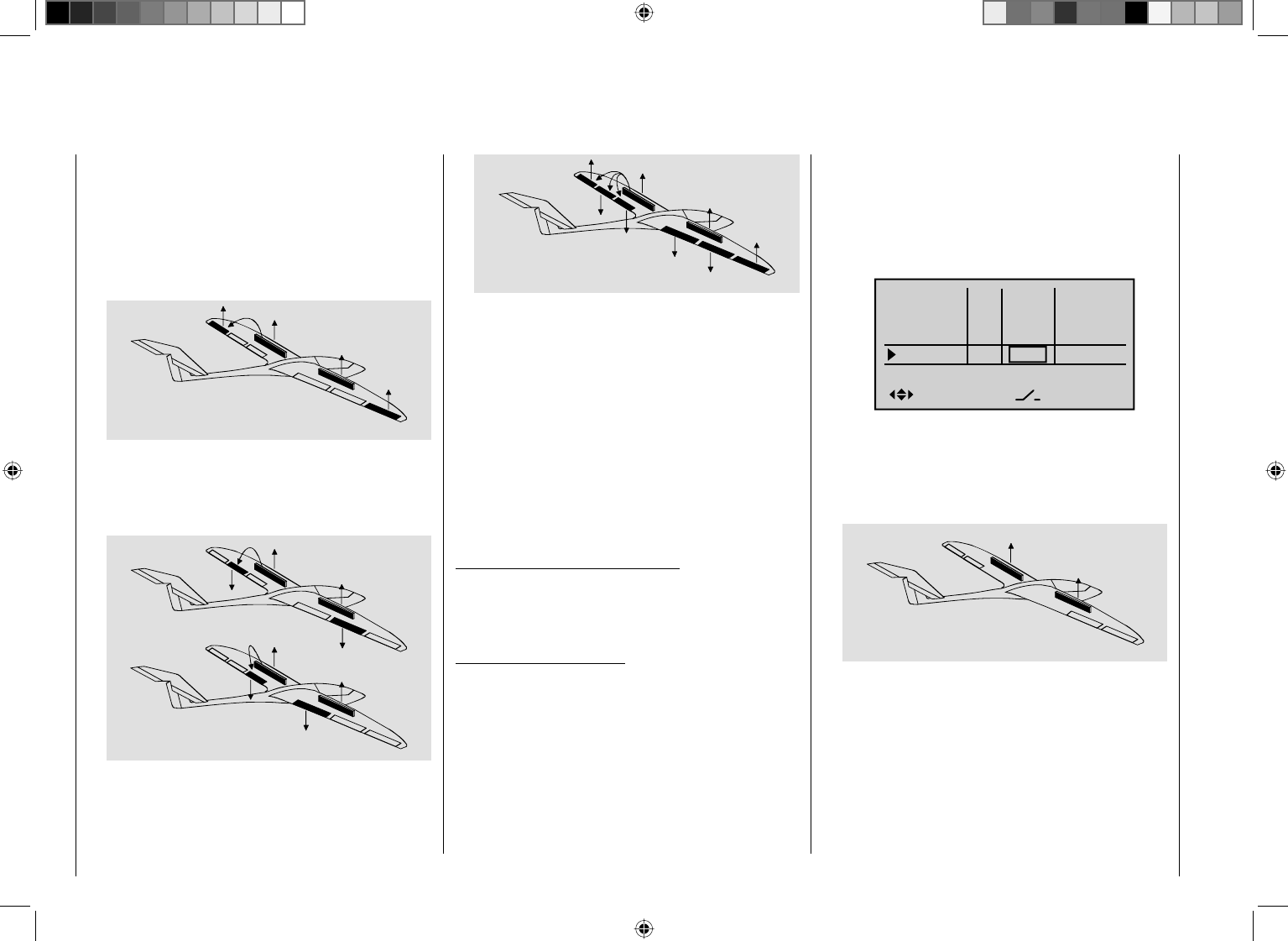
160 Detail program description - Control adjust
AI
FL
FL2
FL2
FL
AI
If the airbrake mixers are set as described above, then a
special fl ap combination – also referred to as the "crow
position" or "butterfl y" – can be confi gured: With this
airbrake setting, both ailerons move moderately upwards
while the fl aps move as far as possible downwards.
A further mixer – see below, under the section "Elevat
curve" – is then used to trim the elevator in such a way that
the model's airspeed changes very little compared to the
normal fl ight position. Otherwise, there is a danger that the
model loses too much speed and then, after the braking
system is retracted (e. g. to extend a landing approach that
was too short, for example), pancakes or even stalls.
A tip for "seeing" the effect of brakes:
lift the fl aps and look over and under the surface from
the front. The larger the surface projected by the lifted
fl ap, the greater the braking effect achieved.
Tips for activating airbrakes:
If you have installed a servo for operating •
conventional wing-mounted airbrakes in addition to
the aileron and fl ap servos, the simplest method of
controlling it is to connect it to the receiver output
whose input you have selected for the brake function,
i. e. either 1, 7, 8 or 9 – assuming it it is free. If this is
not possible, then as an alternative you can set a free
mixer, which connects up the brake control channel
you have selected with the airbrake servo channel.
To activate two airbrake servos, the best approach •
is to leave one servo on output 1 and to connect the
second servo to a free output of your choice – for
example, output 8. You then also assign this output
to transmitter control 1 (as standard) on the "Control
adjust" menu (page 96) – see screen image:
Input 5
offset
0%
0%
0%
–––
0%
Input 6
Input 7
Input 8
–––
–––
GL
GL
GL
GL
typ
normal
Ct1
As you do, leave the settings for offset, travel, etc. at
their default values. Also leave the default value at
"GL" in the "typ" column, since the second airbrake,
like the fi rst, should be active in the same way across
all fl ight phases.
AI
FL
FL
AI
Servo 1
Servo 9
You can assure yourself that this works as stated
by accessing the "Servo display" menu, which you
can access from almost any menu level by briefl y
pressing the ef keys on the left touch pad at the
same time (see page 230):
"AILE" column•
When braking the model as it comes in to land,
neither of the two aileron fl aps should ever be
defl ected more than half of the possible travel
upwards, to ensure that enough travel is available to
control the model along its longitudinal axis (aileron
function).
AI
FL
FL2
FL2
FL
AI
"FLAP" (and "FLAP2") column•
As the model is braked on the landing approach,
both pairs of fl aps can be set to defl ect by different
amounts, e. g.:
AI
FL
FL2
FL2
FL
AI
AI
FL
FL2
FL2
FL
AI
Combining AILE and FLAP for "Crow"•
161
Detail program description - Control adjust
1
3
5
7
+
0%
0%
9
11
0%
0%
2
4
6
8
+
0%
0%
0%
0%10
12
0%
0%
+100%
+100%
If this relatively simply variant should prove
impossible for whichever reasons, then the
alternative is a solution with two free mixers – and
potentially involving the "MIX-only channel" menu
(see page 193).
In either case, however, the airbrake travels must
then be fi ne-tuned on the "Servo adjustment" menu
(see page 90).
D.red. (Differential reduction)
Elevat curve
BRAKE SETTINGS
AILE
Crow
D.red
0%
0%
0%
0%
0%
0%
FLAP FLAP2
Earlier, we discussed the problems with the butterfl y
(crow) confi guration. Namely: that with the use of aileron
differential, the aileron effect can be strongly (negatively)
affected by the aileron elevation. This is fi rstly because
further defl ection of the one aileron upwards is
(almost) no longer possible and secondly because the
downward-defl ected aileron – depending on the elevation
and degree of differential confi gured – is often unable to
achieve even its "normal" position.
To be able to restore the effect of the aileron altered
in this way as far as possible, you should ensure that
you make use of the automated "Differential reduction"
feature. This feature continuously reduces the degree of
aileron differential as the airbrake system is extended.
The feature is confi gurable and can even be set to
suppress differential entirely.
A value of 0% means that the "aileron differential" set
at the transmitter remains fully in force. An entry that
equals the % value set for aileron differential means the
differential is fully eliminated once the butterfl y function
is at maximum travel, i. e. with fl aps fully extended.
Setting a reduction value greater than the aileron
differential confi gured will eliminate the latter even
before the full travel of the airbrake joystick.
Values can be set in the range 0 to150%.
If you tap the cd or ef keys on the right touch
pad (CLEAR) at the same time, this will reset values
changed in the active (highlighted) fi eld back to 0%.
Elevat curve (Brake ¼ elevator)
Elevat curve
BRAKE SETTINGS
Crow
D.red
0%
0%
0%
0%
0%
0%
If the airbrake control – to be set to 1, 7, 8 or 9 on the
"Brake Off" line of the "Model type" menu (page 83) – is
used to extend the fl aps as described previously for the
"Brake settings" menu, this will often have a negative
effect on the aircraft model's airspeed. This mixer can
be used to compensate this type of effect by applying a
corrective value to the elevator.
By briefl y tapping the center SET key on the right touch
pad, you can switch to the display screen as shown below:
Input
Output
Point ?
–100%
0%
0%
Brake
normal
Ele
Curve off
Normal
Confi guration notes for "Elevat curve" (brake ¼ EL)
The offset that you have confi gured on the "Model type"
menu (page 82) affects this mixer:
The vertical line on the display that indicates the
position of the airbrake control only moves from
the edge of the graph when the confi gured offset is
exceeded. Simultaneously, the airbrake control travel is
automatically expanded back to 100%, as described for
the "Model type" menu.
Accordingly, the mixer's neutral point always lies on the
left edge, independently of the offset confi gured.
Now adjust the elevator curve in the direction of the
opposite end-point in accordance with the requirements.
Note that the approach taken to confi guring this 5-point
curve mixer follows the same principles as already
described (within the scope of the "Channel 1 curve"
menu, page 116) as applicable to the curve mixers, i. e.:
Input
Output
Point 1
–19%
–6%
–7%
Brake
Normal
EL
Curve on
162 Detail program description - Control adjust
In each case, you should test the setting selected at
the appropriate altitude and re-adjust as required. As
you do, however, ensure that your model does not slow
down excessively with the braking system extended!
Otherwise, you run the risk that, after the braking
system is retracted, e. g. to extend a landing approach
that was too short, for example, your model pancakes or
even stalls.
Aileron differential
(Only for "2AIL 1FL". If "2AIL 2/4 FL" is selected,
included on the multi-fl ap menu, see page 157.)
Aile.diff
Brake settings
0%
AI 0%
WING MIXERS
–––
RU
Multi-flap menu
Normal
On this line you can set the aileron differential for the
two aileron servos.
If you are unsure about the meaning of differential
travel, please read the appropriate explanation at the
start of this section on page 148.
The adjustment range of -100% to +100% makes
it possible to set the correct direction of differential
regardless of the direction of rotation of the aileron and
fl ap servos.
If you tap the cd or ef keys on the right touch
pad (CLEAR) at the same time, this will reset values
changed in the active (highlighted) fi eld back to 0%.
Aileron ¼ rudder
Brake settings
AI 0%
WING MIXERS
FL EL 0%0%
–––
–––
RU
Multi-flap menu
Normal
Here, you can set the degree to which the rudder follows
commands acting on ailerons. This is used in particular
in connection with aileron differential to suppress
adverse yaw and thus make it easier to fl y "clean"
curves. You can of course still issue separate commands
to the rudder.
The mixer direction is typically chosen to ensure that
the rudder moves in the direction of the aileron that is
defl ected upwards.
Settings are always made symmetrically relative to the
neutral point of the aileron joystick.
The adjustment range of ± 150% lets you set the
direction of defl ection as appropriate. Optionally, this
mixer can be activated and deactivated by using one of
the switches that do not reset themselves (SW 2 … 8) or
a control switch. This means you can then also control
the model using only the ailerons or rudder, as required.
If you tap the cd or ef keys on the right touch
pad (CLEAR) at the same time, this will reset values
changed in the active (highlighted) fi eld back to 0%.
A value of around 50% is generally an excellent starting
point.
Flap ¼ elevator
Brake settings
AI 0%
WING MIXERS
FL EL 0%0%
–––
–––
RU
Multi-flap menu
Normal
When setting camber-changing fl aps, one side-effect
can be to generate moments causing movement around
the transverse axis. Equally, however, it may also be
desirable that e. g. your aircraft model opts for a more
pacey fl ight style with the fl aps slightly raised. This mixer
can be used to achieve both results.
With this mixer, the extension of the fl aps – depending on
the value confi gured – automatically ensures the elevator
position follows suit. Symmetrical or asymmetrical
settings relative to the neutral point of the fl ap control
are possible.
If required, the mixer can be switched on or off by
assigning a switch in the right column.
Values can be set in the range ±150%. The "typical"
values confi gured for this mixer are single-digit or low
two-digit values.
If you tap the cd or ef keys on the right touch
pad (CLEAR) at the same time, this will reset values
changed in the active (highlighted) fi eld back to 0%.
Note:
If you have used the "Control adjust" menu to assign a
transmitter control or switch, as described under ʆ" on
page 159, then the latter will also affect this mixer.

163
Detail program description - Control adjust
164 Detail program description - Control adjust
Helicopter mixers
Flight phase-specifi c setting of collective pitch, throttle and tail rotor
On this menu …
Free mixers
MIX active/phase
Fl. phase timers
Helicopter mixer
MIX-only channel
Dual mixer
… all of the fl ight phase-specifi c helicopter mixers are
described, with the exception of the mixers for auto-
rotation fl ight (discussed from page 178 onwards.)
These mixers are used for the basic set-up of a model
helicopter.
For fl ight phase programming, see the menus:
"• Base setup model", page 74
"• Phase settings", page 132
"• Phase assignment", page 134
When you actuate a switch for a specifi c fl ight phase,
then the associated fl ight phase, e. g. "Normal", is
displayed at the lower left edge of the display screen:
C1
C1
Pitch
Throttle
Tail
Tail 0%
Roll 0%
Throttle
Roll
Throttle
Tail
Nick
Nick
Throttle
Tail
Swash rotation
Swash limiter
0%
0%
0%
0°
OFF
Normal
Gyro suppress 0%
In each of these fl ight phases – with the exception of
the auto-rotation phase – the typical helicopter mixing
and coupling functions shown in the screen-shot
above are available for setting up the model helicopter.
These functions are described in the fi rst part of this
comprehensive chapter.
General information on mixers,
(see also pages 145 and 180)
An arrow "¼" indicates a mixer. A mixer "branches off"
the signal fl ow of a control function at a particular point,
in order to use this fl ow to cause a predetermined effect
on a further control channel and, ultimately, the receiver
output. The "Nick ¼ Tail" mixer, for example, means
that the tail rotor servo will be confi gured to follow
commands from the pitch-axis joystick.
Basic programming procedure:
Select the mixer by using the arrow keys on the left 1.
or right touch pad.
Depending on the mixer, the lower line of the display
will show SEL or the " " icon, which indicates that
you need to move to a second page.
The linear mixer ratios can be set directly by briefl y 2.
tapping the center SET key on the right touch pad:
Use the arrow keys to confi gure the mixer ratio.
Otherwise you will need to switch to the second
screen page where you can set up the appropriate
curve mixer.
If you tap the cd or ef keys on the right touch
pad (CLEAR) at the same time, this will reset values
changed in the active (highlighted) fi eld back to 0%.
Complete the confi guration by tapping the center 3.
SET key on the right touch pad again.
You can page back by tapping the center 4. ESC key on
the left touch pad.
Description of helicopter mixers
To confi gure collective pitch curve settings and the two
mixers "Channel 1 ¼ Throttle" and "Channel 1 ¼ Tail
rotor", curve mixers are available in all fl ight phases.
Accordingly, these mixers also permit the programming
of non-linear mixing ratios along the path of joystick
travel, if required. Switch to the display screen for curve
settings by briefl y tapping the center SET key on the
right touch pad – see discussion below.
The curve is set up basically in the same way as the
Channel 1 curve for helicopters, but we will describe
it again here in detail using pitch configuration as an
example, to save you having to leaf through the manual.
In the remaining lines, fi rst activate the value fi eld and
then use the arrow keys on the left or right touch pad to
set a mixer value in the value fi eld (now highlighted).
The settings available are rounded off with the "swash
limiter" option: These option can be confi gured to
limit the maximum defl ection of the swashplate servo.
Together, these settings confi gure the basic set-up of
the helicopter model.
In the "Autorotation" fl ight phase as described on page
178, however, the mixers "C1 ¼ Throttle" and "C1
¼ Tail" are not needed and therefore switched to a
confi gurable default value.
If you want to reset any changed parameters to
their default values, you can do so at any time by
simultaneously tapping the cd or ef keys on the
right touch pad (CLEAR).
Collective pitch (Collective pitch curve (C1 ¼ Pitch))
If necessary, use the arrow keys cd on the left or right
touch pad to move to the "Pitch" line. Now briefl y tap the
center SET key on the right touch pad:
165
Detail program description - Control adjust
Input
Output
Point ?
0%
0%
0%
Pitch
Normal
Curve off
Unlike the "Channel 1 curve" menu, however, this
display relates only to the control curve of the pitch
servos: the "Channel 1 curve", on the other hand, affects
all servos controlled via the throttle/collective pitch stick.
Note that the output signal of the "Channel 1 curve"
option thus functions as an input signal for the
collective pitch curve programmed here: In the
graph, the vertical line is synchronized with the
throttle/collective pitch stick and therefore follows
the current Channel 1 curve characteristic.
The control curve can be defi ned (separately per fl ight
phase) by up to 6 points, termed "reference points",
placed at any point along the joystick travel.
Initially, however, fewer reference points are adequate
for setting up the collective pitch curve. We recommend
beginning with three reference points to start with. These
three points – namely the two end-points "Pitch low (L)"
(= -100% control travel) and "Pitch high (H)" (= +100%
control travel) plus a point at the center of control travel
still to be set – defi ne an initial linear profi le for the
collective pitch curve.
Programming details
First, switch to your chosen fl ight phase, e. g. "Normal".
The throttle/collective pitch stick is used to move the
vertical line in the graph between the two end-points
"Point L" (minimum pitch at -100%) and "Point H"
(maximum pitch at +100% control travel): at the same
time, the current joystick position is shown numerically
on the "Input" line (-100% to +100%).
The point at which the vertical line crosses the curve is
termed the "Output", and can be varied at the maximum
of 6 reference points within the range -125% to +125%.
A control signal modifi ed in this way affects only the
collective pitch servos.
In the example to the left, the joystick is at exactly 0% of
control travel and also generates an output signal of 0%,
since the characteristic curve is linear.
Up to 4 additional reference points can be set between
the two end-points "L" and "H", although the distance
between neighboring reference points must not be less
than approx. 25%.
Setting reference points
If necessary, use the left or right arrow key d to drag
the marker frame downwards, until it is at the "Point"
line:
?
0%
0%
0%
Pitch
Input
Output
Point
Normal
Curve off
Move the joystick. If the display shows a framed
question mark, then you can set the next reference point
by tapping the center SET key on the right touch pad.
Simultaneously, the "?" is replaced by its number and
the value fi
eld to the right of the reference point number
is highlighted:
1
0%
0%
Pitch
0%
Input
Output
Point
Normal
Curve off
The order in which you generate the (maximum) 4
reference points between the end-points "L" and "H" is
irrelevant, since the reference points are continuously
renumbered automatically from left to right as they are
entered.
Confi guring reference points
To confi gure a point, use the joystick to move the vertical
line onto the point you wish to change. The number
and current curve value of this point are displayed on
the left side of the display, on the "Point" line. Briefl y
tap the center SET key on the right touch pad. Use the
arrow keys on the right touch pad to change the current
curve value shown in the highlighted fi eld. The possible
range is -125% to +125% and changes do not affect
neighboring reference points.
+75%
+75%
Input
Output
Point 1
0%
Pitch
Normal
Curve off
In this sample screen image, reference point "1" has
been set to +75%.
If you wish, however, other points can also be set. At
-50%, for example …
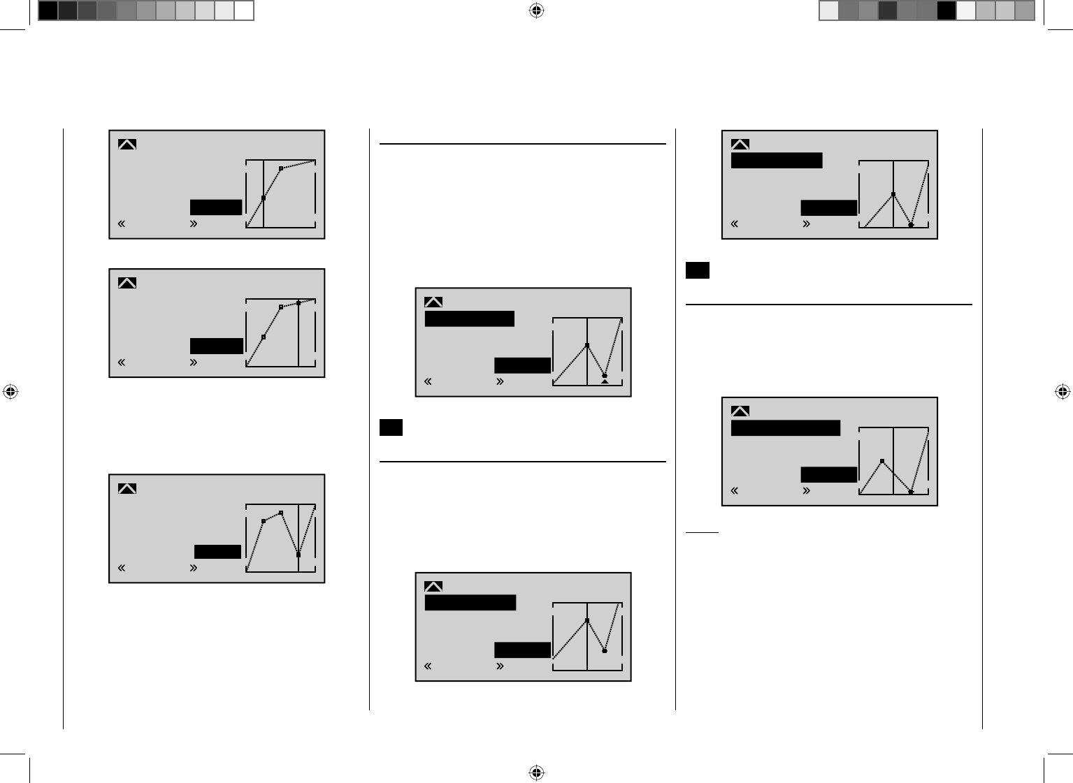
166 Detail program description - Control adjust
–50%
–12%
Input
Output
Point 1
Pitch
Normal
Curve off
–12%
… and/or a further point at +50%:
+50%
+88%
3
Pitch
+88%
Input
Output
Point
Normal
Curve off
To do so, use the joystick to move to the corresponding
area. As soon as a "?" appears in the frame on the
"Point" line, the respective point can be set by pressing
the arrow keys on the right touch pad. Just as with other
points, this can be confi gured …
+50%
–50%
–50%
3
Pitch
Input
Output
Point
Normal
Curve off
… or, by tapping the arrow keys cd or ef on the
right touch pad at the same time (CLEAR), can be
deleted once again.
The "L" and "H" points, on the other hand, CANNOT be
deleted.
Trim point function
Alternatively, assuming the value fi eld is active, i. e.
highlighted, you can use the up or down arrow keys
ef on the left touch pad to jump to reference points
already set. In this case, a triangle is shown on the
graph to indicate each point jumped to. The arrow keys
on the right touch pad can then be used to change the
reference point jumped to as described above, entirely
independently of the control position:
2
+50%
–75%
Pitch
–75%
Trim point
Input
Output
Point
Normal
Exit from trim point function setting by tapping the center
ESC key on the left touch pad.
Trim offset function
Assuming the value fi eld is active, i. e. highlighted, you
can not only use the up or down arrow keys ef on the
left touch pad to jump to reference points already set
and change their values, but you can also use the cd
keys on the left touch pad to vertically reposition an
existing curve within the range ±25%:
1
0%
+50%
Pitch
+50%
Trim offset
Input
Output
Point
Normal
1
0%
0%
Pitch
0%
Trim offset
Input
Output
Point
Normal
You can also exit from this function by tapping the center
ESC key on the left touch pad.
Trim x-axis function
This function is activated by tapping the left (e) or right
(f) arrow key on the right touch pad with an active
(i. e. highlighted) value fi eld. You can then use the arrow
keys on the right touch pad to reposition the active point
horizontally or vertically as you wish.
?
0%
–33%
Pitch
0%
Trim X-axis
Input
Output
Point
Normal
Notes:
If you reposition the point horizontally further away •
from the current control position than approx. ±25%,
a "?" sign re-appears in the line. This question mark
does not refer to the repositioned point, however:
instead, it signifi es that a further point can be set at
the current control position.
Please note that the percentage value on the •
"Output" line always relates to the current joystick
position and not to the position of the point.
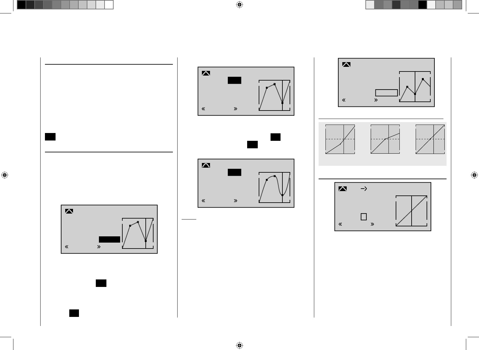
167
Detail program description - Control adjust
Deleting reference points
To delete one of the reference points (1 to max. 4), use
the joystick to move the vertical line into the vicinity of
the reference point in question. As soon as the reference
point number and its associated value is shown on
the "Point" line (see screen image above), you can
activate the value fi eld on the "Point" line to highlight
it by simultaneously tapping the cd or ef keys on
the right touch pad (CLEAR) and then delete the value.
Complete the operation by briefl y tapping the center key
ESC on the left touch pad.
Smoothing the collective pitch curve
In the example below, sample reference points have
been set …
Reference point 1 to +50%
Reference point 2 to +75%
Reference point 3 to -50%
… as described in the last section.
+50%
–50%
–50%
3
Pitch
Input
Output
Point
Normal
Curve off
This "jagged" curve profi le can be smoothed
automatically simply by pressing a button.
First – assuming a situation is confi gured as presented
above – tap the center ESC button on the left touch pad
to deactivate the value fi
eld. Then use the arrow keys on
the left or right touch pad to move the marker frame in
an upwards direction to the "Curve" line. Now briefl y tap
the center SET key on the right touch pad to activate the
value fi eld on the "Curve" line:
+50%
–50%
–50%
3
Pitch
off
Input
Output
Point
Normal
Curve
Use the arrow keys on the right touch pad to set the
value fi eld from "off" to "on" and complete this setup
procedure by briefl y tapping the center SET key on the
right touch pad or the center ESC key on the left touch
pad:
+50%
–50%
–50%
3
Pitch
on
Input
Output
Point
Normal
Curve
Notes:
If the joystick does not coincide with the exact •
reference point, please note that the percentage
value on the "Output" line always relates to the
current joystick position.
As with the other screen images on these pages, the •
following screen shot shows a control curve created
purely for the purposes of illustration. Please note,
therefore, that the curve characteristics displayed
do not in any way represent real-life collective pitch
curves.
0%
–50%
–50%
2
Pitch
Input
Output
Point
Normal
Curve off
Sample collective pitch curves for various fl ight phases:
+100% +100% +100%
-100%
-100%
-100%
Output
Output
Output
234 51234 51234 51
Control travel Control travel Control travel
Hover Aerobatics 3D
C1 ¼Throttle (Throttle curve)
0%
0%
0%
C1 Throttle
?
Input
Output
Point
Normal
Curve off
Unlike the "Channel 1 curve" menu, however, this
display relates only to the control curve of the throttle
servo: the "Channel 1 curve", on the other hand, affects
all servos controlled via the throttle/collective pitch stick.
Note that the output signal of the "Channel 1
curve" menu thus functions as an input signal for
the throttle curve programmed here: In the graph,
the vertical line is synchronized with the throttle/
collective pitch stick and therefore follows the
current Channel 1 curve characteristic.
The throttle curve can also be defi ned (separately
168 Detail program description - Control adjust
per fl ight phase) by up to 6 points, termed "reference
points", placed at any point along the joystick travel.
The reference points are defi ned, adjusted and erased
in the usual way, as explained in the previous section on
the collective pitch curve. Start by defi ning the throttle
curve with three points, namely the points "L" and "H"
at the extremes, plus the Point "1" still to be set in the
control center in order to match the motor power curve
to the collective pitch curve.
Helicopter with carburetor or electric drive system
with speed CONTROLLER
This setting relates only to the control curve of the
throttle servo or the speed controller.
Setting the throttle curve to suit a helicopter equipped
with a speed governor is discussed in the following
section.
As with the confi guration of the collective pitch curve
(see previous page), the throttle curve can also be
defi ned by up to 6 points.
In each case, set the control curve so that when the •
throttle/collective pitch stick is in its end position,
the carburetor is fully open or the controller of an
electrically-powered helicopter is set to maximum
(except for auto-rotation fl ight, see page 178).
For the hover point, which is normally at the control •
center, the carburetor setting or power control for the
speed controller must be matched to the collective
pitch curve so that the correct system rotational
speed is obtained.
At the minimum position of the throttle/collective •
pitch stick, the throttle curve must fi rst be confi gured
so that a glow motor runs at a speed considerably
higher than idle speed and the clutch is fi rmly
engaged.
The starting and stopping of the motor – whether
glow or electric – always takes place using the
throttle limiter (see below) within the respective
fl ight phase.
This makes it unnecessary to program the two fl ight
phases that may be familiar to you from using other
remote control systems – namely "with idle-up" and
"without idle-up", and with the associated "waste" of a
fl ight phase for this purpose – since the mc-32 HoTT
program offers a much more fl exible approach to fi ne-
tuning and optimizing increases to system rotational
speed below the hover point than the "idle-up" approach
taken by older mc radio control units.
Ensure that the throttle limiter is closed before you start
the carburetor motor, i. e. so that the carburetor can
be adjusted within the idle range only by using the idle
trim. Ensure that you follow the safety instructions on
page 177 at all times. If the throttle is set too high when
switching on the transmitter, you will receive audible and
visible warnings!
STARLET
#02
2:22h
Stop
Flug
K78
0:00
0:00
5.5V
5.2V
99%
«Normal »
M
Throttle
too
high!
The following three graphs show (typical) 3-point throttle
curves for various flight phases, such as hovering
aerobatics and 3D flight.
Sample throttle curves for various fl ight phases:
+100% +100% +100%
-100%
-100%
-100%
Output
Output
Output
234 51234 51234 51
Control travel Control travel Control travel
Hover Aerobatics 3D
Notes on using the "throttle limit" function:
You should make use of the throttle limit function as •
a general rule (menu "Control adjust", page 104).
This will fully isolate the throttle servo from the
throttle curve with the throttle limit proportional rotary
169
Detail program description - Control adjust
control turned fully to the left; the motor will be idling
and respond only to C1 trim. This option permits you
to start and also stop the motor from within any fl ight
phase.
Once the motor has started, turn the throttle limiter
slowly in the direction of the opposite end-point, so
you can once again activate the throttle servo fully
using the throttle/collective pitch stick. To stop the
throttle limiter limiting the throttle servo at its top end-
point, you should access the "Th.L.12" line on the
"Control adjust" menu and set the control travel to
+125% on the plus side of the "travel" column. Leave
the default value of "GL" in the "Type" column alone,
however, to confi gure this setting globally for all fl ight
phases.
For a more fi nely-tuned control travel curve for the
throttle limit control, you can also use the "Expo
throttle limiter" (page 107). This gives you the option
of defi ning the idle setting at the throttle limit control's
center position, as readily determined both visually
and audibly.
Set the throttle limiter to its center position and adjust
the "EXPO thro lim." value as far as is needed until
the motor is idling smoothly with the proportional
rotary control set at its center point. In this position,
the motor will then start without any problems. To
switch off, you will turn the throttle limit control – thus
without also using C1 switch-off trim – to its rearmost
end-point. As you do, ensure that the affected servo
cannot hit an end-stop mechanically.
The throttle restriction set by the throttle limiter is
made visible as a horizontal bar in the diagram:
0%
0%
0%
C1 Throttle
?
Input
Output
Point
Normal
Curve off
The output signal for the throttle servo can never
be higher than that set by the horizontal bar. In this
example, it is thus max. ~50%.
Since electric drive systems have no need for an •
idle setting, the basic configuration of settings for
an electrically-powered helicopter merely involves
making sure that the control range of the throttle
limiter is both higher and lower than the adjustment
range of the speed controller (usually -100% to
+100%) by a safe margin. If necessary, therefore,
adjust the "travel" setting of the throttle limiter as
appropriate on the "Th.L.12" line of the "Control
adjust" menu. Leave the default value of "GL" in
the "Type" column alone, however, to confi gure this
setting globally for all fl ight phases.
Fine-tuning of the throttle curve itself, however, must
take place in fl ight – as with a glow-powered heli.
If you wish to record the fl ight time of a (glow-•
powered) heli, you can assign a control switch to the
throttle limit slider, and then use this to switch a timer
on and off; see page 123.
For auto-rotation fl ight, an automatic switch-over
is made from this mixer to a confi gurable default
value; see page 178.
Helicopter with speed GOVERNOR
Unlike speed controllers, which merely adjust the
output level – in a way similar to a carburetor – a
speed governor keeps the speed of the system it is
controlling constant by regulating the output provided
autonomously. For glow-powered helis, the governor
therefore controls the throttle servo itself as appropriate
– or the speed controller of an electric heli in a
comparable way. Accordingly, speed governors do not
therefore require a traditional throttle curve but a speed
setting. A deviation from the preset speed will therefore
only take place if the level of output required exceeds
the maximum level available.
Usually, receiver output 8 is reserved for connecting a
speed governor; see the receiver assignments on page
59. If this connection is in use, however, then the throttle
limiter function is unavailable, since this exclusively
affects the then unoccupied output 6, via the mixer
"C1 ¼ Throttle".
To still make use of the comfort- and safety-related
features of the throttle limiter, you should ignore the
general connection advice and connect the speed
governor to receiver output 6. You then need only adjust
the throttle curve appropriately, so this can take over the
role of the "usual" transmitter control.
Since in this case the "throttle curve" only regulates the
target speed of the motor controller and this target motor
speed should typically remain constant over the entire
collective pitch adjustment range, the "C1¼ Throttle"
mixer must be used to set a horizontal line – i.e. every
(pitch) input value will result in the same ("throttle")
output value – whose "height" is defi ned by the target
motor speed.
First, therefore, the reference points "1" to "4" – if
170 Detail program description - Control adjust
C1 ¼Tail (Static torque compensation)
0%
0%
0%
Tail
C1
?
Input
Output
Point
Normal
Curve off
The default approach here is to preset a torque
compensation curve with a linear mixer ratio of a uniform
0%, as is required for a gyro sensor working in "heading
lock mode" – see the screen image above.
Important notice:
In this context, ensure that you comply with the
instructions on adjusting your gyro: if not, you
risk making adjustments that render your heli
impossible to fl y.
If, on the other hand, you use your gyro sensor in the
"normal" operating mode, or if it only has what is termed
"normal mode", then confi gure the mixer as follows:
As with the confi guration of the collective pitch curve
(see page 165), the control curve of the tail rotor can
also be defi ned by up to 6 points. If required, therefore,
you can modify the mixer at any time and preset both
symmetrical and asymmetric mixer ratios both above
and below the hover point. Before you do, however,
ensure you have entered the correct direction of rotation
for the main rotor on the "Helicopter type" menu.
present and set – are erased. Following this, the
reference points "L" (input = -100%) and "H" (input
= +100%) are then each set to the same value, for
example:
–100%
+30%
+30%
C1 Throttle
L
Input
Output
Point
Normal
Curve off
The value to be set depends both on the speed
governor used and on the target motor speed that is
desired, and can, of course, be varied according to the
fl ight phase.
For auto-rotation fl ight, an automatic switch-over
is made from this mixer to a confi gurable default
value; see page 178.
+100%
+30%
Tail
C1
H+30%
Input
Output
Point
Normal
Curve off
Starting with values of -30% for point "L" and +30% for
point "H", the mixer is to be configured in such a way
that the helicopter, even during prolonged vertically
ascending or descending flights, does not deviate from
the yaw axis as a result of the main rotor's altered
torque while hovering. For hovering, trim should take
place only via the (digital) tail rotor trim lever.
For a reliable torque compensation setting, it is essential
that the collective pitch and throttle curves have been
set up correctly, i.e. that the rotor speed remains
constant over the collective pitch's full adjustment range.
This third curve mixer applies only to the control curve
of the tail rotor servo when the throttle/collective pitch
stick is moved, whereas the "Channel 1 curve" (see
page 119) acts on all servos that are affected by the
throttle/collective pitch stick. Note that the output signal
of the "Channel 1 curve" option also functions as an
input signal for the tail rotor curve programmed here:
In the graph, the vertical line is synchronized with the
throttle/collective pitch stick and follows the current
Channel 1 curve characteristic from the "Channel 1
curve" menu.
In the auto-rotation fl ight phase this mixer is
automatically switched off.
171
Detail program description - Control adjust
rotor defl ection. Set the mixer value so that there is no
fall-off in system rotational speed.
Roll ¼ Throttle and Nick ¼ Throttle
C1 Tail
Tail 0%
Roll 0%
Throttle
Throttle
SEL
Roll Tail
Nick Throttle
0%
0%
Normal
Increasing collective pitch is not the only change that
requires the throttle to follow suit: major cyclic control
movements also require this, i. e. if the swashplate is
tilted in any direction. The mc-32 HoTT program lets
you adjust the degree of throttle follow separately for roll
and pitch-axis controls.
This offers particular advantages in aerobatic fl ying, e. g.
when fl ying a roll: here, with moderate collective pitch
values and the carburetor only about half-open, cyclic
control travels are nonetheless executed that require
much higher performance from the motor.
The mixer value can be varied within the range 0 to
+100%. The correct mixer direction is automatically
taken into account.
If you tap the cd or ef keys on the right touch
pad (CLEAR) at the same time, this will reset values
changed in the active (highlighted) fi eld back to 0%.
In the auto-rotation fl ight phase this mixer is
automatically switched off.
Tail rotor ¼ throttle
C1
C1
Pitch
Throttle
Tail
Tail 0%
Roll 0%
Throttle
Throttle
SEL
Normal
While the tail rotor normally compensates for the effect
of main rotor torque on the fuselage, it is also used to
control the helicopter around the vertical axis. Increasing
tail rotor thrust requires a corresponding adjustment
to motor power, however, to avoid a fall-off in system
rotational speed.
This mixer sets the extent to which the throttle follows
the tail rotor. The throttle will follow on one side only,
to the side on which the tail rotor thrust is increased.
Values in the range 0% to +100% are therefore possible.
The direction depends on the main rotor's direction of
rotation (left or right), and this must fi rst be set correctly
on the "Helicopter type" menu. For left-hand rotation
systems, the throttle follows the tail rotor when the tail
rotor joystick is moved to the left, and vice versa for
right-hand rotation systems.
If you tap the cd or ef keys on the right touch
pad (CLEAR) at the same time, this will reset values
changed in the active (highlighted) fi eld back to 0%.
In the auto-rotation fl ight phase this mixer is
automatically switched off.
Set-up notes:
To set the mixer value accurately you should either fi rst
fl y several high-speed pirouettes against the direction of
main rotor rotation or, if a strong wind is blowing, hover
at right angles to the wind with a suffi ciently large tail
Roll ¼ Tail and Nick ¼ Tail
0%
Roll
0%
Throttle
SEL
Roll Tail
Nick Throttle
0%
0%
0%
Nick Tail
Gyro suppress
Normal
Increasing pitch is not the only change that requires a
corresponding torque compensation via the tail rotor:
major cyclic control movements also require this, e.g.
if the swashplate is tilted in any direction. Here, too,
the mc-32 HoTT program lets you confi gure settings
for both types of tilt movement (roll and pitch-axis)
separately.
For advanced aerobatics in particular, which involve
very large control defl ections in the pitch-axis
controls, e. g. the "Bo-turn" (vertical pull-up followed
by tipping over around the pitch-axis) and tight loops,
the uncompensated torque present in these fl ights
causes the model to turn to a greater or lesser degree
around the yaw axis. This spoils the appearance of the
maneuver.
These two mixers permit static torque compensation to
be activated by the swashplate tilting in any direction.
The mixers work by always increasing tail rotor thrust,
starting from the center point of the roll and pitch-axis
sticks, i.e. they always generate a tail rotor defl ection
in the same direction regardless of the direction of the
command.
The mixer value can be varied within the range 0 to
+100%.
The mixer direction is determined automatically by your
defi nition of the direction of main rotor rotation on the
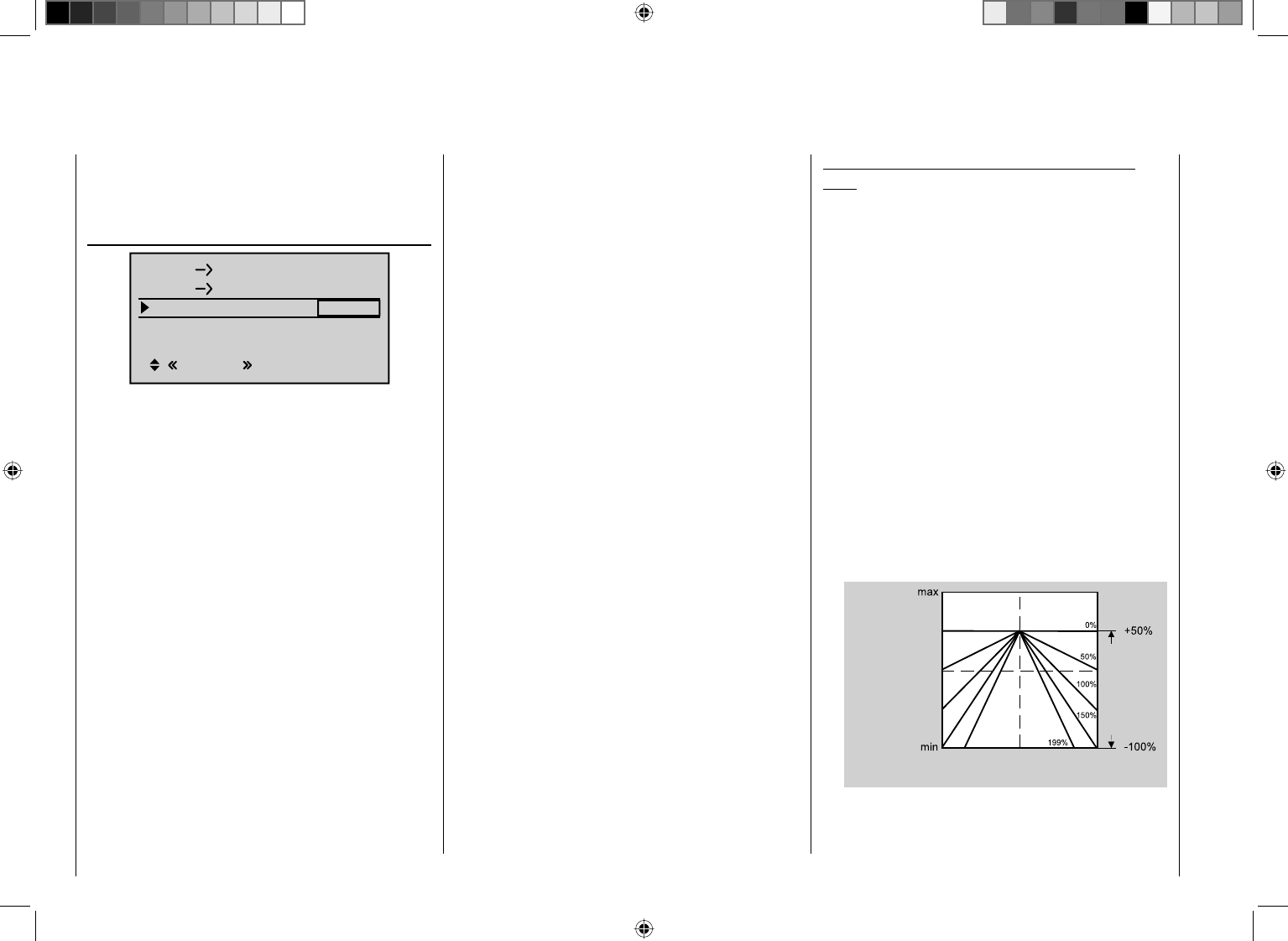
172 Detail program description - Control adjust
"Helicopter type" menu, page 86.
In the auto-rotation fl ight phase this mixer is
automatically switched off.
Gyro suppression
0%
0%
SEL
Nick Throttle
0%
0°
Nick Tail
Swash rotation
Swash limiter OFF
Normal
Gyro suppress
Important: in normal situations, this function should
not be used if your model is fi tted with a modern
gyro system. In this context, ensure that you comply
with the instructions on adjusting your gyro: if not,
you risk making adjustments that render your heli
impossible to fl y. This menu has nonetheless been
retained in order to cater to a full range of requirements
and fl ying habits.
With this option, the effect of the gyro sensor ("gyro")
can be varied according to the tail rotor joystick position;
this assumes the use of a gyro system whose gyro gain
can be controlled from the transmitter via an auxiliary
channel. This channel will be channel 7 for Graupner
radio control systems. The gyro suppression function
reduces gyro gain in a linear progression as the
pilot increases the tail rotor defl ection. Without gyro
suppression – i.e. when set to 0% – the gyro effect is
constant, regardless of the joystick position.
With a transmitter control assigned on the "Gyro 7" line
on the "Control adjust" menu (page 103), however,
e. g. one of the CTRL 7 or 8 proportional rotary controls,
the gyro gain can also be infi nitely varied (optionally
according to the fl ight phase) between minimum and
maximum gain. In this case, gyro gain is maximum at full
defl ection of the slider, and zero at the opposite end-
point.
Of course, the software lets you limit the gyro gain range
on both sides by altering the transmitter control travel.
Depending on the transmitter control position, the gyro
gain at full travel on the tail rotor joystick is:
"current control position
minus
gyro suppression value".
Accordingly, if the transmitter control is at the neutral
point, and gyro suppression is set to 100%, the gyro
gain is reduced to zero as the tail rotor defl ection
increases. For values between 100% and the maximum
value of 199%, the gyro can be fully suppressed –
depending on the transmitter control position – well
before full defl ection of the tail rotor; see the diagram on
the next page.
For the Graupner/JR gyro NEJ-120 BB, order no. 3277,
both the upper and the lower values are set via rotary
controls: control 1 sets the minimum gyro gain at the
bottom position of the slider; control 2 sets the maximum
gain at the top end-point of the slider; the transition
between these two values occurs roughly in the middle
of the slider travel.
In contrast, the PIEZO 900, PIEZO 2000 and PIEZO
3000 gyro systems feature proportional, infi nitely
variable adjustment of gyro gain; see below for typical
diagrams.
As an example, the option to confi gure fl ight phase-
specifi c – and static – gyro gain gives you the opportunity
to exploit maximum stabilization for normal, slow fl ying,
but to reduce gyro gain for fast circuits and aerobatics.
Samples of various gyro settings and confi guration
notes
Linear gyro suppression: 0% to 199%. •
With the tail rotor joystick in the center position,
the resulting gyro effect is set using the selected
transmitter control. Using a proportional rotary
control, the effect is infi nitely variable between zero
("min") and maximum ("max"), provided transmitter
control travel is not restricted. With full tail rotor
defl ection, the effective gyro gain is as follows:
"current control position
minus
gyro suppression value".
Accordingly: at 0% gyro suppression, gyro gain
is constant for tail rotor joystick movement; at
50% suppression, gyro gain is reduced to half if
the assigned transmitter control is moved to the
+50% position (as shown here); and only at >150%
suppression is gain reduced to zero with the slider at
this position, well before full tail rotor defl ection.
Exemple:
+50 %
Í Gyro gain Î
left
Stick deflection tail rotor
centre right
Range of
transmitter
control 7
Linear gyro suppression with reduced control travel, •
e. g. -50% to +80% of full travel.
Gyro gain is infi nitely variable within these transmitter
173
Detail program description - Control adjust
control limits. Here too, for purposes of illustration, we
plot gyro gain values in relation to tail rotor defl ection
for various parameter values of gyro suppression.
Exemple:
+80 %
Í Gyro gain Î
left
Stick deflection tail rotor
centre right
Range of
transmitter
control 7
Adjusting the gyro sensor
To achieve the maximum possible level of stabilization
for the helicopter with the gyro along the vertical axis,
observe the following:
The controls should have as little friction and "play" •
as possible.
There should be no "spring" in the control linkage.•
Use a strong and – in particular – a fast servo •
When the gyro sensor detects a model rotation, the
faster its response – a corresponding corrective change
to tail rotor thrust – takes effect, the further the gyro
gain adjustor can be moved without causing the tail of
the model to start oscillating, and the better the model's
stability about its vertical axis. If the response is slower,
there is a risk that the model's tail will start to oscillate
even at low gyro gain settings. Here, further reductions
to gyro gain will need to be made to eliminate the
oscillation.
If the model is fl ying forward at high speed or hovering
in a powerful headwind, the net result of the stabilizing
effect of the vertical fi n combined with the gyro may
also lead to an overreaction that once again manifests
itself through tail oscillation. To achieve optimum gyro
stabilization under all conditions, you can make use of
the option to adjust gyro gain from the transmitter using
a transmitter control assigned to input "7", in connection
with gyro suppression and/or the two settings on the
Gyro NEJ-120 BB.
Further notes on gyros with confi gurable multilevel gyro
gain (e. g. NEJ-120 BB)
Since you cannot specify the gyro gain from the
transmitter proportionally via the transmitter control, the
gyro's own control 1 must be used to set the (weaker)
gyro gain (e. g. for aerobatics) and control 2 the stronger
gyro gain (e. g. for hovering ). Even though a proportional
rotary control is used for control function 7, only a
switch-over between these two values takes place and
the setting is therefore not proportional.
You should therefore advance control 2 to the point
where the model is on the brink of oscillating when
hovering in calm conditions, and advance control 1 to
the point where the model does not oscillate with its
tail even when fl ying at maximum speed into a strong
headwind. Depending on the state of the weather
and the fl ight program planned, you can also switch
over the gyro gain from the transmitter – also with
gyro suppression dependent on tail rotor defl ection if
required.
Swashplate rotation
0%
0%
SEL
0%
0°
Nick Throttle
Nick Tail
Swash rotation
Swash limiter OFF
Normal
Gyro suppress
Some rotor head control systems make it necessary
to incline the swashplate in a different direction from
the intended inclination of the rotor plane when a cyclic
control command is given. If your model features a
four-bladed main rotor, for example, you may need to
use this menu to set up a software-driven 45° rotation
of the control linkage to the right, so that the pushrods
from the swashplate to the rotor head can be set exactly
vertical, ensuring that the blade control system works
correctly, without unwanted differential effects. This
eliminates the need to make mechanical changes to
the control linkages. Negative angles equate to a virtual
rotation of the rotor head to the left; positive angles a
virtual rotation to the right.
Swashplate limiting
0%
0%
SEL
0%
0°
Nick Throttle
Nick Tail
Swash rotation
Swash limiter OFF
Normal
Gyro suppress
This function works like a circular mechanical surround
acting upon the stick which controls the swashplate,
restricting the normally square stick travel to a circular
range. In fact, if the helicopter is set up in such a way
174 Detail program description - Control adjust
that the defl ections for roll and/or pitch-axis exploit the
maximum travel mechanically possible, e. g. for 3D helis,
then the total tilt applied to the swashplate if full roll
and pitch-axis commands are applied simultaneously
will be considerably greater (141% in numerical terms).
The swashplate mechanism may then strike its end-
stops and in the worst case the ball-links could even be
disengaged.
The mc-32 HoTT transmitter contains a confi gurable
software function for limiting the total swashplate travel,
i.e. it restricts the tilt angle of the swashplate from 100%
(the travel is limited to the value obtainable either with
roll or pitch-axis alone) to 149% (no effective limit). In
addition, the function can be set to "Off" and hence
completely deactivated. The swash limiter can also be
confi gured per model and per fl ight phase.
This software solution is therefore much more fl exible
than a physical circular surround attached to the stick
unit: the latter can, in any case, only be used if the roll
and pitch-axis functions are controlled by a common
stick unit.
The sketch shown alongside
illustrates the effect when set
to 100%: the cross-hatched
area of travel is curtailed and
appears as a "dead zone".
If this function is used, "Dual
Rate" should be set to 100%
and Dual Rate values above
100% should also not be
used. If not, and you set a
swashplate limit of 100%, for example, then swashplate
movement will be restricted even if roll and pitch-axis
commands are given separately.
Adjustment range: 100 ... 149% and "Off".
175
Detail program description - Control adjust
Fine-tuning the throttle and collective pitch curve
Practical approach
Although the throttle and collective pitch control systems
are based on separate servos, they are always operated
together by the throttle/collective pitch stick (except
during auto-rotation fl ight). This coupling is performed by
the helicopter program automatically.
In the mc-32 HoTT program, the trim lever of control
function 1 acts principally only on the throttle servo.
However, in the "Stick mode" menu (see page 94)
you can determine whether this should be used for idle
trimming as part of the throttle limit function, or for idle
trimming during the auto-rotation phase ("throttle AR").
The process of fi ne-tuning throttle and collective
pitch, i. e. setting the motor power curve to match the
collective blade pitch setting, is the most important
aspect of setting up a model helicopter. The mc-32
HoTT software provides for independent confi guration
of the throttle, collective pitch and torque compensation
curves, in addition to the C1 control curve ("Channel 1
curve" menu, page 119).
While these curves can be modeled using up to
six points, fewer points are generally suffi cient. We
recommend starting with three-point curves to begin
with. This involves setting individual values for the center
point and other (optional) reference points, and for the
two end-points ("L", "low", and "H", "high") of the throttle/
collective pitch stick: together, these defi ne the control
curves.
Before setting the throttle and collective pitch function,
however, you should accurately calibrate the mechanical
linkages for all the servos, following the set-up
instructions for the helicopter in question.
Note:
The hover point should normally be set to the center
position of the throttle / collective pitch stick. For
some special cases, however, e. g. for "3D" fl ight,
you may wish to program hover points that deviate
from this standard. For example: one point for
normal fl ight attitude above the center and one point
for inverted fl ight attitude below the center.
Idle setting and throttle curve
Note:
Since electric drive systems have no need for an idle
setting, motor idling does not need to be calibrated.
Fine-tuning of the throttle and collective pitch curve(s),
however, must take place as for glow-powered helis.
The idle setting described in detail on pages 105 to
107 always takes place with the throttle limiter closed –
normally with the trim lever of the C1 function and only
in special cases is the throttle limiter itself also utilized
(as standard, the CTRL 6 proportional rotary control).
The programming of a corresponding value for the "L"
point of the throttle curve acts to set the descent speed
of the motor, without infl uencing the hover confi guration.
Here, for example, you can use fl ight phase
programming in order to confi gure a range of throttle
curves. This increased system rotational speed
below the hover point proves to be useful in certain
circumstances, for example for fast, steep landing
approaches with greatly reduced collective pitch, and for
aerobatics.
The screen image depicts a curve
with a slightly changeable throttle
setting below the hover point at
the control center. Control travel
OUTPUT
Different throttle curves are programmed for each fl ight
phase, so that you can use the optimum set-up for both
hovering and aerobatics:
Low system rotational speed with smooth, gentle •
control response and low noise when hovering
Higher rotor speed for aerobatics with motor power •
set close to the maximum. In this case, the throttle
curve must also be adjusted in the hover range.
Basic set-up procedure
While the mc-32 HoTT transmitter permits the
electronic confi guration of collective pitch curve and
throttle curves to a large degree, fi rst ensure that you
have correctly set all of the model's mechanical linkages
as specifi ed by the helicopter manual. Experienced
helicopter pilots will be glad to help you with this basic
set-up.
The carburetor linkage must be set so that the throttle is
just past the fully open setting with collective pitch set to
maximum or, for electric helis, with the speed controller
set to full. When the throttle limiter is closed, however,
it must be possible to just close off the carburetor using
the C1 trim lever (rapid throttle setting of the "digital
trim", see page 54), without the servo mechanically
striking its end-stop. For electric helis, it must be
possible to cut the electric motor's speed controller
safely with the throttle limiter closed.
Take great care when confi guring these settings, by
adjusting the control linkage as required and/or altering
the linkage point on the servo or carburetor lever. Only
then should you optimize throttle servo fi ne-tuning
electronically.
Caution:
Inform yourself thoroughly about the dangers and
176 Detail program description - Control adjust
pitch setting for the hover and the maximum collective
pitch setting (point "H") now provides you with a simple
method of achieving constant system rotational speed
from hovering right through to maximum climb.
First, perform a prolonged, vertical climb by moving
the collective pitch stick to its end-point. Compared to
the hover confi guration, motor speed should remain
unchanged.
If motor speed falls off in the climb, even with the drive
system working at full power and therefore no further
power increase is possible, then reduce maximum
blade pitch angle at full defl ection of the collective
pitch stick, i.e. the value of point "H". Conversely, you
should increase the angle of attack if the motor speed
increases during the climb. On the "Pitch" graph page,
you should therefore use the collective pitch stick to
move the vertical line to point "H" and change its value
accordingly, using the arrow keys cd on the right
touch pad.
This diagram shows only the
changes when setting the
maximum collective pitch value.
+100%
-100%
OUTPUT
234 51
Control travel
Hover
point
Then bring the model back to hover, which should, in
turn, be achieved with the C1 stick at its center point.
If the hover point is now achieved only by moving the
collective pitch stick from the center point towards
"higher" values, then you should compensate for this
hover deviation by slightly increasing collective pitch for
hover – i.e. for point "1" – until the model once again
hovers with stick at its center. Conversely, if the model
safety precautions applicable to handling motors
and helicopters before starting the motor for the
fi rst time!
With this basic set-up complete, the motor should
be started in accordance with the motor operating
instructions: idling can then be confi gured using the trim
lever of the throttle/collective pitch stick. The idle position
that you set is displayed on the transmitter's basic
display by a horizontal bar alongside the display of the
C1 trim lever position. Refer to the description of digital
trim on page 54 of this manual.
The model should lift off the ground with the collective
pitch stick roughly at its center point and hover roughly
at the expected rotational speed. If this is not the case,
proceed as follows:
1. The model does not lift off until the collective
pitch stick is above the center point.
a) Rotational speed is too low
Remedy: On the graph
page of the "C1 ¼
throttle", increase the
value for point "1".
+100%
-100%
OUTPUT
234 51
Control travel
Hover
point
b) Rotational speed istoo
high
Remedy: Increase the
blade angle of attack pitch
by increasing the value
of point "1" on the "Pitch"
graph page.
+100%
-100%
OUTPUT
234 51
Control travel
Hover
point
2. The model lifts off before the center point is
reached.
a) Rotational speed is too
high
Remedy: Decrease the
carburetor opening by
reducing the value of point
"1" on the graph page of
the "C1 ¼ throttle".
+100%
-100%
OUTPUT
234 51
Control travel
Hover
point
b) Rotational speed is too low
Remedy: Decrease the
blade angle of attack pitch
by reducing the value of
point "1" on the "Pitch"
graph page.
+100%
-100%
OUTPUT
234 51
Control travel
Hover
point
Important:
These settings must be reconfi gured until the model
hovers at the correct rotational speed with the throttle/
collective pitch stick at its center point. The confi guration
of all other model parameters depends on these settings
being made correctly!
Standard set-up
Standard set-up is completed on the basis of the basic
set-up described above, whereby the model hovers
in normal fl ight at the correct rotational speed with
the throttle/collective pitch stick set to its center point:
This means a set-up with which your model is capable
of hovering and fl ying circuits in all phases while
maintaining a constant rotational speed.
Climb settings
The combination of throttle hover setting, collective
177
Detail program description - Control adjust
blades spinning wildly.
Always make sure that nobody else
is standing near the helicopter
where they could be injured.
In addition, you must never switch abruptly from idle
to the fl ight setting by suddenly increasing system
rotational speed. This will cause the rotor to accelerate
very quickly, resulting in premature wear to the clutch
and gear train. Since the main rotor blades are generally
mounted on a freewheeling unit, they will be unable
to keep pace with such rapid acceleration; they will
respond by swinging far out of their normal position and
may even cause a boom strike.
After starting the motor, you should therefore use the
throttle limiter to increase the system rotational speed
slowly. If you have assigned a switch to the throttle
limiter, always ensure that you use the "Control adjust"
menu (page 100) to program a time constant of about
5 seconds for running up the system rotational speed
(opening the throttle limiter). Do not, however, program
a delay for closing the throttle limiter. Leave the default
value of "GL" in the "Type" column alone, however, to
confi gure this setting globally for all fl ight phase
Once the model can fl y this maneuver properly, set the
value for "Throttle min" – the value for point "L" on the
graph page for "C1 ¼ throttle" – so that the rotational
speed neither increases nor decreases. This completes
the set-up procedure for throttle and collective pitch.
Some important closing remarks
Before starting the motor, ensure that the throttle limiter
is fully closed: this ensures that the carburetor now
responds only to the C1 trim lever. If the carburetor is
open too far when you switch on the transmitter, you will
receive a visual and audible warning. Otherwise, if the
carburetor or speed controller is open too far when the
motor starts, there is a danger that the motor will run up
to speed immediately after starting, and the centrifugal
clutch will engage immediately.
Accordingly, you should
always hold the rotor
head fi rmly when starting.
However, if you should accidentally start the motor with
the carburetor too far open, the golden rule is this:
Don't panic!
Keep hold of the rotor head !
Don't let go!
Instead, close the throttle limiter immediately, even if
this risks damaging the drive system (in the worst case
scenario).
YOU are responsible for ensuring
that the helicopter never fl ies off
in an uncontrolled manner.
The costs of repairing a clutch, a gearbox or even the
motor itself are negligible, if you compare these to
the injuries and damage that an uncontrolled model
helicopter can cause if it is allowed to fl y around with its
hovers below the mid-point, correct this by reducing the
angle of attack appropriately.
You may also fi nd that it is necessary to correct the
carburetor opening for the hover point (point "1") at "C1
¼ throttle".
This diagram shows only the
change to the hover point, i. e.
collective pitch minimum and
maximum are both left at -100%
or +100%.
+100%
-100%
OUTPUT
234 51
Control travel
Continue adjusting these settings until you really do
achieve a constant rotational speed over the full control
range between hover and climb.
Descent setting
The descent setting should now be confi gured by
placing the model in a steady descent from forward fl ight
at a considerable altitude by fully reducing collective
pitch; adjust the collective pitch minimum value (point
"L") so that the model descends at an angle of 60° …
70°. On the "Pitch" graph page, you should therefore
use the collective pitch stick to move the vertical line
to point "L" and change its value accordingly, using the
arrow keys on the right touch pad.
This diagram shows only the
changes when setting the
minimum collective pitch value.
+100%
-100%
OUTPUT
234 51
Control travel
Hover
point
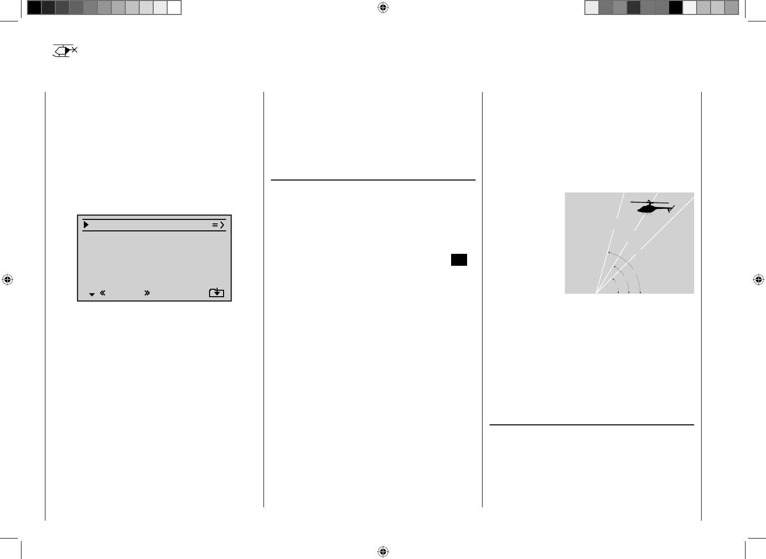
178 Detail program description - Control adjust
Auto-rotation permits both full-size and model
helicopters to land safely in a crisis, e. g. if the motor
should fail. Moreover, if the tail rotor should fail, cutting
the motor and landing using auto-rotation is also the
only possible way to avoid a high-speed, uncontrollable
rotation around the vertical axis and a resulting
catastrophic crash. Accordingly, switchover TO the auto-
rotation phase takes place immediately.
When the switchover to the auto-rotation phase is made,
the Helicopter mixer menu screen changes as follows:
Pitch
Thr setting AR
Tailoffset AR
Gyro suppress 0%
Swash rotation 0°
OFF
Autorot
–90%
0%
Swash limiter
During auto-rotation fl ight, the main rotor is no longer
driven by the motor, but only by its own momentum
and the the airfl ow through the rotor disc caused by the
rapid descent. Since the energy stored by a rotor kept
spinning in this way is rapidly consumed if the helicopter
fl ares, pilots must not only have experience in handling
helicopter models but must also consider carefully how
the relevant functions should be confi gured.
The advanced pilot should therefore practice auto-
rotation landings at regular intervals. Not only to be
able to demonstrate mastery of the maneuver at
competitions, but also to ensure the pilot can can land
the helicopter undamaged from a great height if the
motor should fail. For this purpose, the program provides
a range of adjustment options designed to help the
pilot fl y a motorized model in its unpowered state. Note
Helicopter mixers
Auto-rotation settings
that the auto-rotation settings comprise a complete
seventh fl ight phase, which provides access to all the
fl ight phase- specifi c confi guration options, and to trims,
collective pitch curve settings, etc., in particular. The
following functions have special features not present in
the powered fl ight phases:
Collective pitch (Collective pitch curve (C1 ¼ Pitch))
In powered fl ight, the maximum blade pitch angle
is limited by available motor power. In auto-rotation,
however, it is limited only by the point at which airfl ow
ceases over the main rotor blades. Greater maximum
collective pitch must therefore be set to ensure suffi cient
thrust when fl aring the helicopter even as rotational
speed is falling off. To do so, briefl y tap the center SET
key on the right touch pad to switch to the "Pitch" graph
page and then use the joystick to move the vertical line
to point "H". Start by setting a value that is about 10%
to 20% larger than your "normal" maximum value for
collective pitch. Initially, however, do NOT set a value
that is considerably greater than for normal fl ight, since
if you do so, the behavior of the collective pitch controls
may then be very unfamiliar following the switchover.
Indeed, there is a danger that the pilot will oversteer
during the fl are and the model will balloon: this will case
the rotor speed to collapse at a considerable altitude
and the model will then crash to the ground. You can
always re-adjust the value later after fl ying some test
auto-rotations.
The minimum value for collective pitch can differ from
that set for normal fl ight. This depends on the pilot's
usual style for normal fl ight. For auto-rotation, however,
you must always set a suffi ciently generous minimum
value for collective pitch at point "L" to ensure your
model can be brought out of forward fl ight at moderate
speed into a descent at an angle of around 60–70°
when collective pitch is reduced to a minimum. If, like
most heli pilots, you have confi gured this kind of setting
for normal fl ight anyway, then you can simply copy this
value across.
If, however, you normally let your model "fall" at a
shallower angle, then you should increase the value at
point "L", and vice versa.
Approach angle for
various wind condi-
tions
Approach angle
in moderate
wind
no wind
45°
60°
75°
in strong
wind
As a rule, the collective pitch stick itself is not positioned
right at the bottom of its travel for auto-rotation. Instead,
it is typically between the hover position and the
bottom end-point, offering the pilot the option of further
adjusting pitch inclination using the pitch-axis controls.
You can shorten the approach by pulling back on the
pitch-axis stick and gently reducing collective pitch, or
extend the approach by pushing forward on the pitch-
axis stick and gently increasing collective pitch.
Throttle setting AR
Although pilots will be expected to cut the glow motor
completely during competitions, this is rather less
advisable during training sessions, since you would then
need to restart the motor following each practice auto-
rotation landing.
During the training phase, you should therefore set the
179
Detail program description - Control adjust
value on this line so that a glow motor is held at a safe
idle during the auto-rotation phase without the clutch
engaging; electric drive systems should be set safely to
"Off".
Note:
You may wish to make use of the "Motor Stop" option
on the "Base setup model" menu as an alternative
"Emergency STOP" function.
Tail rotor AR
In normal fl ight, the tail rotor is set so that it
compensates for motor torque while the model is
hovering. It therefore generates some a certain amount
of thrust even in its normal position. The level of thrust is
then varied by the tail rotor control system, and also by
the various mixers which provide all manner of torque
compensation, while the tail rotor trim is also used to
compensate for varying weather conditions, fl uctuations
in system rotational speed and other infl uences.
For auto-rotation, however, the main rotor is not driven
by the motor, but by the "windmill" principle. Since this,
in turn, does not generate any torque for which the tail
rotor must compensate, all corresponding mixers are
switched off automatically.
Since the absence of torque in auto-rotation also means
the above-mentioned thrust is superfl uous, however, a
different tail rotor confi guration is also required:
Cut the motor and place the helicopter on the ground in
a level attitude. With the transmitter and receiving system
switched on, select the fl ight phase "Auto-rotation" and
then fold the tail rotor blades down. Now change the
value on the "Tail rotor" line until the tail rotor blade angle
of attack is zero degrees. Viewed from the tail, the tail
rotor blades should be parallel to one another.
Depending on the friction and running resistance of the
gearbox, the fuselage may still yaw slightly, however. This
relatively slight torque must then be corrected if necessary
by adjusting the tail rotor blade pitch angle. This value
will always be a fi gure between zero degrees and a pitch
angle opposed to the pitch angle in normal fl ight.
180 Detail program description - Control adjust
General notes on freely programmable mixers
The previous pages have described a wealth of ready-
to-use built-in coupling functions, in the context of the
two menus "Wing mixers" and "Helicopter mixers".
The fundamental signifi cance of mixers and the principle
by which they work are described on page 145. The
following section presents you with information relating
to "free mixers".
In addition to the pre-programmed mixers previously
mentioned, the mc-32 HoTT offers a number of freely
programmable mixers in every model memory, whose
inputs, outputs and mixer ratios can be confi gured to suit
your exact requirements:
8 linear mixers, numbered M1 to M8•
4 curve mixers, numbered K9 to K12•
These 12 mixers are certainly adequate for most
applications and are invariably suffi cient when you
incorporate the pre-programmed coupling functions
offered. On the "Mix active/phase" menu (see page
192), you are also free to specify which of these
12 mixers is activated or deactivated separately for each
fl ight phase.
For the "free mixers", the signal present at any control
function (1 to 12) can be assigned as the input signal.
For the "switch channel" (see further below), the signal
from any switch can be utilized. The signal that is
present at the control channel and passed to the mixer
input is always infl uenced by its own transmitter control
and by any control characteristic that may have been
set, e. g. those specifi ed by the "Dual Rate / Expo",
"Channel 1 curve" and "Control adjust" menus.
The mixer output acts on a control channel (1 to 12,
depending on receiver type) that can also be assigned
freely. Before this channel routes the signal to the servo,
it can be infl uenced only by the "Servo adjustments"
menu, i.e. by the the servo reverse, neutral point offset,
servo travel and servo travel limit functions, and also
possibly by " Tx. output swap ".
One control function can be used for any number of mix
inputs simultaneously: if, for example, several mixers
should be switched to act in parallel.
Conversely, it is possible for any number of mixers to
affect one and the same control channel. Particularly in
the latter case, however, it is very important to ensure
that the servo concerned does not strike its mechanical
end-stops when several mixer signals accumulate
to an excessive extent. For safety's sake it may be
worth setting an appropriate travel limit on the "Servo
adjustments" menu in such cases.
For more complex applications, mixers can be switched
in sequence. In this case, it is not the (transmitter) signal
at the "output" of a control function which forms the input
signal of the "series-wired" mixer, but the (mixed) signal
"further back" at the "input" of a control channel. The
following description of the free mixers includes several
examples of this type.
In the software, one "free mixer" is always initially
activated. If you wish, however, the mixer can also be
assigned an ON/OFF switch. Since there are so many
functions to which switches can be assigned, you must
be careful to avoid undesirable multiple assignments.
The two key mixer parameters are:
… •the mixer ratio, which defi nes the extent to which
the input signal acts on the output of the control
channel connected to the mixer output.
If you are using linear mixers, the mixer ratio can be
set as symmetrical or asymmetric. Curve mixers can
also be confi gured with up to 6 points to suit your
application, enabling the implementation of highly
non-linear curves.
… •the neutral point of a mixer, which is also
referred to as the "offset".
The offset is the specifi c point along the travel of a
transmitter control (joystick, CTRL 6 … 8 proportional
controls or switches 1 … 9) at which the mixer no
longer infl uences the control channel connected to
its output. Normally, the neutral point is the center
point of the transmitter control. However, the offset
can also be set at any other point along the control
travel. Since there are no restrictions on the design
of the curve mixers, setting a mixer neutral point only
makes sense for the 8 linear mixers.
Switch channel "S" as a mixer input
Occasionally, however, only a constant control signal is
required at the mixer input. A typical application would
be a slightly increased "up-elevator" trim when the aero-
tow release is closed – fully independently of its normal
trim setting.
In this case a switch is assigned both to the aero-tow
release and the mixer; it is then used not only to open
and close the release, but also to pass the desired trim
signal to the elevator via the mixer ratio. To identify this
special arrangement, this mixer input control function in
the program is designated "S" for "Switch channel".
In addition, if the corresponding "target channel" should
now no longer be infl uenced by its "normal" transmitter
control, then you should isolate the latter from the
function input of the affected control channel on the
"MIX-only channel" menu (page 193). In the menu
description that follows, an example is also given to
illustrate this function.
Using the arrow keys on the left or right touch pad, page
181
Detail program description - Control adjust
Basic programming procedure
Select the mixer you want by using the arrow keys 1.
cd on the left or right touch pad.
Tap the center 2. SET key on the right touch pad. The
input fi
eld on the line marked "fr" at the lower edge of
the screen is now shown highlighted.
Use the arrow keys on the right touch pad to select 3.
the "fr" mixer input.
Tap the center 4. SET key on the right touch pad; using
the arrow key f on the left or right touch pad, switch
to the column marked "to" on the lower edge of the
screen and then tap the center SET key on the right
touch pad once again.
The input fi eld "to" is shown highlighted.
Use the arrow keys on the right touch pad to select 5.
the "to" mixer output.
Tap the center 6. SET key on the right touch pad.
Optionally, use the arrow key e on the left or right
touch pad to switch to the column marked "ty" on
the lower edge of the screen, in order to include
the trim of the respective joystick in the mixer input
signal ("Tr" for trim) and/or to add series switching for
mixers …
… and/or use the arrow key f on the left or right
touch pad to switch to the column marked with the
switch icon on the lower edge of the screen.
Here, tap the center SET key on the right touch
pad once again and assign a switch, following the
description given in the section "Assigning transmitter
controls, switches and control switches" (page 52).
Using the arrow key 7. f on the left or right touch pad,
switch to the column and then tap the center SET
key on the right touch pad.
to the menu option …
MIX active/phase
Fl. phase timers
Wing mixers
MIX-only channel
Dual mixer
Free mixers
MIX active/phase
Fl. phase timers
Helicopter mixer
MIX-only channel
Dual mixer
Free mixers
… on the multi-function list. Briefl y tap the center SET
key on the right touch pad to open this menu option.
Free mixers
Freely-programmable linear and curve mixers
Regardless of the model type you have selected, each
of the 24 model memory slots will offer you eight linear
mixers (M1 … M8) …
Ty p fr zu
M1
M2
M3
?? ??
?? ??
M4
M5
?? ??
?? ??
?? ??
… and 4 curve mixers (K9 … K12), which also offer you
the option of setting non-linear control characteristics:
Ty p fr zu
M8
C9
C10
?? ??
?? ??
C11
C12
?? ??
?? ??
?? ??
In addition, the "MIX active/phase" menu (page 192)
enables you to enable and disable particular mixers
separately for specifi c fl ight phases. On the "Free
mixers" menu, the blocked mixers are then
suppressed in the corresponding fl ight phase. If
you are hunting for a mixer that is not shown, you
should therefore switch to the appropriate fl ight
phase!
In this fi rst section, however, we will concentrate on how
to program the fi rst screen page of the "free mixers". We
will then move on to the method of programming mixer
ratios, both for linear mixers and curve mixers, as found
on the second screen page of this menu.
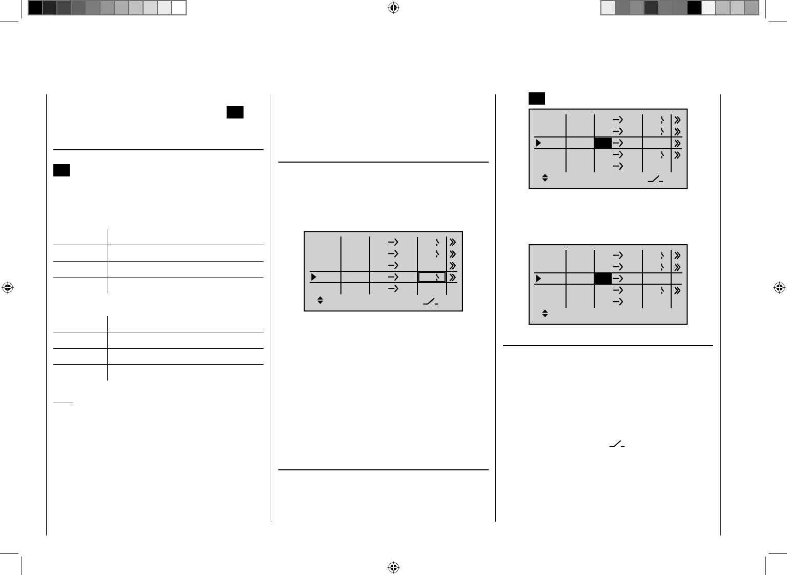
182 Detail program description - Control adjust
the previous page.
After assigning a control function or the "S" switch
channel in the "fr" column, the following is also displayed
…
" to"
… on the lower edge of the screen.
You use the input fi eld in this column to route the
destination of the mixer, i. e. the mixer output, to one of
the control channels. At the same time, additional fi elds
also appear on the bottom line of the screen :
ty fr to
M1
M2
M3
6EL
C1 EL
M4
M5
3 8
SEL
?? ??
Tr C4
4
2
In this example, four mixers have already been defi ned.
The second mixer is already familiar to us in principle as
"Elevat curve" from the "Brake settings" sub-menu on the
"Wing mixers" menu, and the third is familiar from the
"Tail" line ("2ELSv3+8") on the "Model type" menu. As a
general rule, however, you should fi rst make use of the
pre-programmed mixers. However, if you need asymmetric
mixer ratios, want to go as far as programming non-linear
curves or need to offset the mixer neutral point, then you
should set or leave the pre-programmed mixers at "0%"
and replace their use with free mixers.
Erasing mixers
If you need to erase a previously-defi ned mixer, select
the appropriate line with the arrow keys cd on the
left or right touch pad, switch to the "fr" column if you
need to with the arrow keys efand then briefl y tap the
center SET button on the right touch pad:
ty fr to
M1
M2
M3
6EL
C1 EL
M4
M5
8
SEL
?? ??
Tr C4
4
2
3
The fi eld in the "fr" column for the mixer you want to
delete will now be shown highlighted: tap both of the
arrow keys cd or ef on the right touch pad at the
same time (CLEAR):
Ty p fr zu
M1
M2
M3
6EL
C1 EL
M4
M5
??
SEL
?? ??
Tr C4
4
2
??
Mixer switches
In the sample screen image shown above, switches "4"
and "2" have been assigned to linear mixers 1 and 4 and
to mixer 2 of the control switch "G4".
The switch symbol to the right of the switch number
shows the current switch state.
Any mixers that have not been assigned any switch,
as shown in the line on the bottom of the screen
marked with a switch icon , are on by default!
A switch must be assigned to the fourth mixer if you wish
to switch between two fi xed mixer values (still to be set)
that correspond to the two end-points of a (proportional)
transmitter control. Accordingly, the "switch channel" mixer
cannot also be switched "on" or "off" as with the other
mixers.
Defi ne the mixer ratios on the second screen page.8.
Return to the fi rst page by using the center 9. ESC key
on the left touch pad.
" fr"
After selecting a mixer line and then tapping the center
SET key on the right touch pad to highlight the value
fi eld, use the arrow keys on the right touch pad to select
one of the control functions: 1 … 12 or S.
For the sake of legibility, control functions 1 … 4 are
marked as follows when setting wing mixers:
C1 Throttle/airbrake stick
AI Aileron stick
EL Elevator stick
RU Rudder stick
… and, for the heli program:
1 Throttle/collective pitch stick
2 Roll stick
3 Pitch-axis stick
4 Tail rotor stick
Note:
If you select control functions 5 … 12 for fi xed-wing
models or 5, 7 … 12 for heli models, do not forget
to assign a transmitter control in each case on the
"Control adjust" menu!
"S" as switch channel
Selecting "S" (switch channel) in the "fr" column has
the effect of passing a constant input signal to the mixer
input, e. g. in order to add a little more "up-elevator" trim
when the aero-tow release is closed, as mentioned on
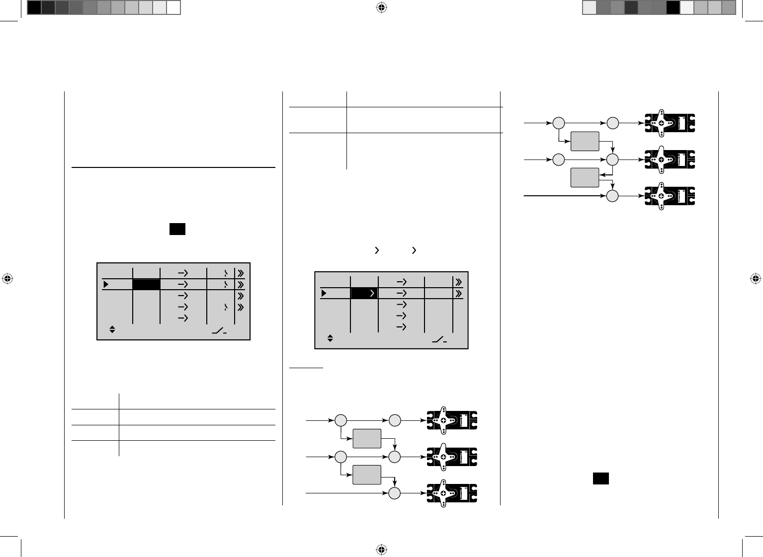
183
Detail program description - Control adjust
Trim Effect on mixer output
AR
(throttle limit)
Linear, over full trim lever travel
GA
(throttle auto-
rotation)
Only effective at minimum position of the
assigned throttle limit control (CTRL 6
proportional rotary control as standard)
Switching mixers in series
As already explained on page 180, you can also
switch mixers in series: Where mixers are switched
in "sequence", the "input signal" of a control channel
already on its way to the servo "branches off" and is
directed to a further channel. In the "ty" column, select
the right angle bracket " " – or "Tr ", if the trim should
also act simultaneously on the mixer input:
ty fr to
M1
M2
M3
67
78
M4
M5 ?? ??
?? ??
?? ??
Example:
Two mixers (MIX 6 ¼ 7 and 7 ¼ 8):
a) WITHOUT series switching:
6 6
7
Servo 4,8 V
C 577
Best.-Nr. 4101
Servo 4,8 V
C 577
Best.-Nr. 41 01
7
8
Servo 4,8 V
C 577
Best.-Nr. 41 01
MIX 1
MIX 2
If you intend to assign a control switch (G1 … G4) as
a switch, then please note that you must defi ne this
appropriately BEFOREHAND on the "Control switch"
menu. If you do not, you will assign an undefi ned control
switch and therefore one that functions as a fi xed switch.
" Ty"
Including the trim
For control functions 1 … 4, you can also confi gure
things so that the trim generated by the digital trim lever
of the respective joystick affects the mixer input. In this
case, briefl y tap the center SET key on the right touch
pad and then use the arrow keys to select "Tr" in the
highlighted fi eld:
ty fr to
M1
M2
M3
6EL
C1 EL
M4
M5
3 8
SEL
?? ??
C4
4
2
Tr
The effect of the C1 trim lever on the mixer output will
depend on the function assigned to it on the "Model
type" menu (page 82), in the "Motor on C1" column for
fi xed-wing models …
Trim Effect on mixer output
None Linear, over full trim lever travel
Forward Only effective if C1 stick is forward
Back Only effective if C1 stick is back
… or on the "Pitch" line of the "Stick mode" menu for
helicopter models:
b) The same mixers WITH series switching:
6 6
7
Servo 4,8 V
C 577
Best.-Nr. 4101
Servo 4,8 V
C 577
Best.-Nr. 4101
7
8
Servo 4,8 V
C 577
Best.-Nr. 41 01
MIX 1
MIX 2
In this highly simplifi ed example, if mixer 2 is switched in
series, then it does not "take over" solely the transmitter
signal of control function 7 – as shown under a) – but,
instead, the entire (mixed) signal present at the servo
side of control channel 7, as shown under b). It then
directs this in accordance with its confi gured mixer ratio
forwards to control channel 8. In this case, the effect of
transmitter control "6" extends as far as output "8". This
kind of serial linkage can be extended as far as you
wish. For example, another mixer "8¼12" can be
used to route the control signal from "6" as far as output
"12", taking into consideration the associated mixer
ratios. Of course, even with an active serial link, each
separate mixer can still be controlled via the transmitter
control assigned to the mixer input. Fixed-wing and
helicopter mixers also work in the same way, when set
up to switch "in sequence".
Including phase trim
If you wish to apply the trim values of the FLAP channel
("6") or the FLAP2 channel ("9") as stored on the
"Phase trim" menu – and dependent on fl ight phase –
then fi rst tap the center SET key on the right touch pad
and use its arrow keys to select "P":
184 Detail program description - Control adjust
* N.N. = Nomen Nominandum (the name to be stated)
ty fr to
M1
M2
M3
611
M4
M5 ?? ??
?? ??
?? ??
P
?? ??
Depending on the mixer value confi gured, a mixer can,
as shown in the example above, route the signal from a
fl ap control present (e.g.) on input 6 to control channel
11, while also applying the FLAP trim value set on the
"Phase trim" menu (page 136) for the respective fl ight
phase.
Other special features of free mixers
Mixer input = mixer output
If you set up a mixer whose input is the same as its
output, e.g. "C1 ¼
C1", you can achieve some very
special effects in conjunction with the option of switching
a free mixer on and off in any way you like. Typical
examples for this feature can be found at the end of this
section as example 2 on page 190, plus others in the
section "Controlling timed sequences" on page 266.
Tip:
If you separate a control function, e.g. "9", from control
channel 9" using the "MIX-only channel" menu (see
page 193), then the servo response is defi ned only
by the mixer ratio (yet to be specifi ed) of the mixer
programmed on the same channel. This enables you
to set up linear curves using mixers M1 … 8 or 6-point
control curves using curve mixers K9 … 12 for any
transmitter control, as described in the "Channel 1
curve" menu, and also include them in fl ight phase
switching if required. This method of "linking" is then
not only also switchable, but can even be subject to a
delay, by assigning an appropriate delay in the "– time
+" column of the "Control adjust" menu. For more
information, see the programming example entitled
"Controlling timed sequences" on page 266.
Mixer output affecting default software coupling of
aileron, camber-changing fl ap or collective pitch
servos
Before we start specifying the mixer ratio, we must
fi rst give some thought to what happens if we permit a
mixer to affect the default software coupling of aileron,
camber-changing fl ap or collective pitch servos:
Fixed-wing models:•
Depending on the number of wing servos set on
the "Aile/fl aps" line of the "Model type" menu,
control channels are connected together via special
mixers as follows: channels 2 and 5 for the "Aileron"
function; channels 6 and 7 for the "Flap" function; and
channels 9 and 10 for the FLAP2 servos (if present).
If mixer outputs are programmed to affect these kinds
of couplings, then their effect on the respective fl ap
pair derived from the "receiving" control channel must
be accounted for:
Mixer Effect
N.N.* ¼ 2 The servo pair 2 + 5 responds with an
aileron function
N.N.* ¼ 5 The servo pair 2 + 5 responds with a
fl ap function
N.N.* ¼ 6 The servo pair 6 + 7 responds with a
fl ap function
N.N.* ¼ 7 The servo pair 6 + 7 responds with an
aileron function
N.N.* ¼ 9 The servo pair 9 + 10 responds with a
fl ap function
N.N.* ¼ 10 The servo pair 9 + 10 responds with
an aileron function
N.N.* ¼ 11 The servo pair 11 + 12 responds with
a fl ap function
N.N.* ¼ 12 The servo pair 11 + 12 responds with
an aileron function
Model helicopters:•
With heli mixers, collective pitch control may be
provided by up to 4 servos connected to receiver
outputs 1, 2, 3 and 5, depending on helicopter type.
The software links these together to control collective
pitch, roll and pitch-axis.
Elsewhere than the "Helicopter mixers" menu,
it is not advisable to mix a free mixer into these
channels, since some extremely complex interactions
can result from such attempts. One of the few
exceptions is "Collective pitch trim using a separate
transmitter control" – see example 3 on page 190.
Important notices:
With serial links in particular, remember that •
that the travels of the individual mixers are
cumulative if multiple stick commands are made
simultaneously: there is a risk that the servo(s)
may strike a mechanical end-stop. If necessary,
reduce "servo travel" to avoid this; alternatively,
set "Travel limit" on the "Servo adjustments"
menu and/or reduce mixer values.
185
Detail program description - Control adjust
Use the option available to you at any time of •
switching to the "Servo display" efmenu (see
page 230). This menu is reached from almost any
menu option on the transmitter's basic display
by briefl y tapping the keys on the left touch
pad at the same time. This menu gives you the
opportunity to check the effects of all of your
settings on a single screen.
Mixer ratios and mixer neutral point
Now that we have explained the wide-ranging nature of
the mixer functions, the following section describes how
to program linear and non-linear mixer curves.
For each of the 12 available mixers, the mixer curves
are programmed on a second page of the screen
display. Use the arrow keys cd on the left or right
touch pad to select the desired mixer line. If necessary,
use the touch pad's arrow keys to move to the right
column ( ), and then briefl y tap the center SET key on
the right touch pad in order to access the graph page.
Mixers M1 … 8: Setting linear mixer values
As a practical example, we will now defi ne a linear mixer
curve to resolve the following problem:
For our motorized aircraft model, the two servos connected
to receiver outputs 6 and 7 – defi ned on the "Aile/fl aps"
line of the "Model type" menu as "… 2FL" – are to
be deployed to activate landing fl aps. That is: when a
transmitter control is moved, they must defl ect downwards
only. This requires a simultaneous elevator trim, however.
First, use the "Control adjust" menu to assign a control
such as the CTRL 6 proportional rotary control to input
6. Comment: in this case, a transmitter control on input
6 will control the two servos connected to receiver
outputs 6 and 7 as fl aps, by default – as you can see by
consulting the above table. Leave the default value of
"GL" in the "Type" column alone, however, to confi gure
this setting globally for all fl ight phases – as is the case
for the free mixer.
"Control adjust" menu
Input 5
offset
0%
0%
0%
–––
0%
Input 6
Input 7
Input 8
–––
–––
GL
GL
GL
GL
typ
normal
Ct6
Note:
Note that if two fl ap servos have been selected, any
transmitter control assigned to input 7 will be decoupled
in the software in order to avoid errors in operating the
fl aps. However, in the interests of safety, you should
make a habit of leaving all inputs not currently required
to "free", or of resetting these back to "free"!
Start by moving this transmitter control to its left end-
point and adjust the landing fl aps so that they are
retracted or closed in this position. If you now move
the dial to the right, the fl aps should move downwards;
if not, you will need to adjust the direction of servo
rotation.
We now turn our attention to the fi rst mixer shown in the
screen image on page 182 ("6 ¼EL"), to which switch 4
was assigned:
ty fr to
M1
M2
M3
6EL
C1 EL
M4
M5
SEL
?? ??
Tr C4
4
2
?? ??
Briefl y tap the center SET key on the right touch pad to
open the second screen page:
OFF
L.MIX 1 6EL
If this screen appears, the mixer has not yet been
activated using the assigned toggle switch – "4", in this
example. If so, operate the switch:
L.MIX 1
0% 0%
0%
Offset
ASY
SYM
6EL
Mix input
The solid vertical line represents the current position of
the transmitter control on input 6. (In the above diagram,
located at the left edge, since the CTRL 7 transmitter
control assigned to input 6 in this example (see previous
page) is turned fully to the left.) The dotted vertical line
in the middle of the diagram indicates the position of the
mixer neutral point – see under "Offset", below. The solid
horizontal line shows the mixer ratio, which currently has
186 Detail program description - Control adjust
the value zero over the entire stick travel; accordingly,
the elevator will not yet follow the movement of the fl aps.
First, the …
Offset (mixer neutral point)
… should be defi ned. To do so, use the arrow key d
on the left or right touch pad to move to the line under
"Offset":
L.MIX 1
0% 0%
0%
Offset
SET
STO
6EL
Mix input
The dotted vertical line in the middle of the diagram
indicates the position of the mixer neutral point
("Offset"), i.e. the specifi c point along the control travel
at which the mixer does NOT infl uence the control
channel connected to its output. The default position for
this point is at the control center.
However, since in our example the fl aps should be
closed or retracted with the proportional rotary control
turned fully to the left, and since the elevator should
also not be further infl uenced in this position, we must
relocate the mixer neutral point to precisely this point. To
do so, turn the transmitter control used (in this example,
CTRL 7) fully to the left if you have not already done
so, and then briefl y tap the center SET key on the right
touch pad. The dotted vertical line moves across to this
point, the new mixer neutral point, which by defi nition
always retains the "initial" value of zero.
However, to illustrate our example better we now
wish to set this "Offset" value to only -75%.
L.MIX 1
0% 0%
–75%
Offset
SET
STO
6EL
Mix input
Notes:
By selecting • SET with the arrow key f on the left or
right touch pad and then tapping the center SET key
on the right touch pad …
L.MIX 1
0% 0%
Offset
SET
STO
6EL
Mix input
–75%
… you can then use the arrow keys on the left or
right touch pad to set or readjust the offset value
manually in increments of 1%.
By selecting • SET and then activating the value fi eld
by tapping the center SET key on the right touch
pad – – see screen image shown above – – you can
then reset the mixer neutral point back to the control
center automatically by simultaneously tapping the
two arrow keys cd or ef on the right touch pad
(CLEAR).
Symmetrical mixer ratios
The next task is to defi ne the mixer values above and
below the mixer neutral point – – – starting from its current
position. Move to the value fi eld on the line beneath the
"Mix input" line, using the arrow key c on the left or right
touch pad if necessary: If required, use the arrow keys
ef on the left or right touch pad to select the SYM fi eld,
so as to confi gure the mixer value symmetrically with the
offset point just set. After briefl y tapping the center SET
key on the right touch pad, you can then use the arrow
keys on the right touch pad to set a value from -150% to
+150% in the two highlighted fi elds. Note that the mixer
value set always refers to the input signal of the respective
transmitter control (control signal)! Negative mixer values
reverse the direction of the mixer.
Simultaneously tapping the two arrow keys cd or ef
on the right touch pad (CLEAR) will erase the mixer
ratio in the highlighted fi eld.
The "optimum" value in our example will certainly need
fl ight-testing.
L.MIX 1
–75%
Offset
ASY
SYM
6EL
Mix input
+20% +20%
Earlier, we set the mixer neutral point at -75% of control
travel: as a result, the elevator ("EL") will exhibit a
(slight) down-elevator effect even at the neutral point
of the landing fl aps and this is naturally undesirable.
Accordingly, you should reposition the mixer neutral
point to -100% of control travel, as described earlier.
187
Detail program description - Control adjust
L.MIX 1
+20% +20%
–100%
Offset
SET
STO
6EL
Mix input
If you were now to reset the offset currently set at -100%
back as far as 0% of control travel – by selecting the
SET fi eld with the arrow keyfon the left or right
touch pad, activating the value fi eld and then tapping
the two arrow keys cd or ef on the right touch pad
(CLEAR), then you will receive the following screen:
L.MIX 1
+20% +20%
0%
Offset
STO
6EL
Mix input
SET
Asymmetric mixer ratios
In many cases, however, we require different mixer
values on each side of the mixer neutral point.
First, reset the offset of the mixer used in the example
"6 ¼ EL" to 0%, if required (see screen image above).
Using the arrow key f on the left or right touch pad,
select the ASY fi eld and then tap the center SET key
on the right touch pad. If you now move the proportional
rotary control assigned to input 6 – in this example,
CTRL 7 – in each of the corresponding directions,
you can use the arrow keys on the right touch pad to
confi gure the mixer ratios for each of the two control
directions, i.e. left and right of the confi gured offset point:
* N.N. = Nomen Nominandum (the name to be stated)
L.MIX 1
0%
Offset
ASY
SYM
6EL
Mix input
+55% +20%
Note:
If you are using a switch channel mixer of the "S ¼ N.N.*"
type, then you need to actuate the assigned switch. The
vertical then jumps between the left and right side.
Setting the curve mixers K9 … K12
These four curve mixers enable you to defi ne extremely
non-linear mixer curves by placing up to 4 freely
positionable points between the two endpoints "L" (low
= -100% control travel) and "H" (high = +100% control
travel) along the control travel.
If you have already read the description of the "Channel
1 curve" menu, or the method of programming 6-point
curves on the "Helicopter mixers" menu, you can
safely skip the following description.
Programming details
The control curve is defi ned by up to 6 points, known as
"reference points". In the default software confi guration,
2 reference points are already defi ned, namely only the
two end-points, "L" and "H"; see the next screen image.
The following section applies to "any" mixer to which we
wish to assign a non-linear curve characteristic.
The examples shown in the following section
are merely illustrative, however, and they do not
represent real-life mixer curves.
–45%
0%
0%
Input
Output
Point ?
C.MIX 9
normal
Curve off
810
Setting reference points
When you move the transmitter control assigned to the
mixer input – here control function 8 – a vertical line
in the graph follows the movement between the two
end-points. The current control position is also shown
numerically on the "Input" line. The point at which this
line intersects with the curve in question is named the
"Output" and can be varied between -125% and +125%
by setting reference points; see further below. This
control signal acts on the mixer output.
In the above example, the transmitter control is on input
8 at -45% of control travel. The output signal continue to
show 0%, however, since no value has yet been entered.
Up to 4 additional reference points can be set between
the two end-points "L" and "H", although the distance
between neighboring reference points must not be less
than approx. 25%.
If necessary, use the left or right arrow keys on the left
or right touch pad to drag the marker frame downwards,
until it is on the "Point" line:
188 Detail program description - Control adjust
–45%
0%
0%
Input
Output
Point ?
C.MIX 9
normal
Curve off
810
When you now briefl y tap the center SET key on the
right touch pad, the "?" is replaced by a point number
and the value fi eld to the right is activated:
–45%
0%
1
810
0%
Input
Output
Point
C.MIX 9
Curve off
Using the arrow keys on the right touch pad you can now
change the point value within the range of ±125%, e. g.:
–45%
+50%
1
normal
810
+50%
Input
Output
Point
C.MIX 9
Curve off
Note:
If the joystick does not coincide with the exact reference
point, please note that the percentage value on the
"Output" line always relates to the current joystick position.
Continue in this way to set other reference points. Note
that the order in which you generate the (maximum) 4
reference points between the end-points "L" and "H" is
irrelevant, since the reference points are continuously
renumbered automatically from left to right as they are
entered.
+35%
–55%
2
normal
810
–55%
Input
Output
Point
C.MIX 9
Curve off
Erasing reference points
To erase one of the reference points between "L" and
"H", use the transmitter control in question to move the
vertical line onto or into the vicinity of the reference point
in question. The reference point number and associated
reference point value are shown on the "Point" line. The
value fi eld is highlighted, see screen image above.
If necessary, use the arrow keys on the left or right touch
pad to move the marker frame onto the "Pitch" line. Now
briefl y tap the center SET key on the right touch pad.
The value fi eld is shown highlighted.
Now tap the two arrow keys cd or ef on the right
touch pad at the same time (CLEAR).
The selected reference point is erased, and the
numbering of the remaining reference points is updated
as required. Briefl y tap the center ESC key on the left
touch pad to complete the procedure.
Note that the reference points "L" and "H" cannot be erased.
Changing reference point values
To change reference point values, use the associated
transmitter control to move the vertical line onto the
point you wish to change: "L", 1 … 4 or "H". The number
and current curve value of this point are displayed. After
activating the value fi eld on the "Point" line by briefl y
tapping the center SET key, use the arrow keys on the
right touch pad to change the current curve value shown
in the highlighted fi eld. The possible range is -125% to
+125% and changes do not affect neighboring reference
points. Briefl y tap the center ESC key on the left touch
pad to complete the procedure.
Trim point function
Alternatively, assuming the value fi eld is active, i. e.
highlighted, you can use the up or down arrow keys
ef on the left touch pad to jump to reference points
already set. In this case, a triangle is shown on the
graph to indicate each point jumped to. The arrow keys
on the right touch pad can then be used to change the
reference point jumped to as described above, entirely
independently of the control position:
+35%
–55%
2
normal
Kurve
810
–55%
Trim point
Input
Output
Point
C.MIX 9
Exit from trim point function setting by tapping the center
ESC key on the left touch pad.
Trim offset function
Assuming the value fi eld is active, i. e. highlighted, you
can not only use the up or down arrow keys ef on the
left touch pad to jump to reference points already set
and change their values, but you can also use the cd
keys on the left touch pad to vertically reposition an
existing curve within the range ±25%:
189
Detail program description - Control adjust
+35%
–30%
2
normal
Kurve
810
–30%
Trim offset
Input
Output
Point
C.MIX 9
+35%
–80%
2
normal
Kurve
810
–80%
Trim offset
Input
Output
Point
C.MIX 9
You can also exit from this function by tapping the center
ESC key on the left touch pad.
Trim x-axis function
This function is activated by tapping the left (e) or right
(f) arrow key on the right touch pad with an active
(i.e. highlighted) value fi eld. You can then use the arrow
keys on the right touch pad to reposition the active point
horizontally or vertically as you wish.
0%
–55%
?
normal
Kurve aus
810
–55%
Trim X-axis
Input
Output
Point
C.MIX 9
Notes:
If you reposition the point horizontally further away •
from the current control position than approx. ±25%,
a "?" sign re-appears in the line. This question mark
does not refer to the repositioned point, however:
instead, it signifi es that a further point can be set at
the current control position.
Please note that the percentage value on the •
"Output" line always relates to the current joystick
position and not to the position of the point.
Smoothing the curve
This "jagged" curve profi le can be smoothed
automatically simply by pressing a button.
Then use the arrow keys on the left or right touch pad
to move the marker frame in an upwards direction to the
"Curve" line, as required. Now briefl y tap the center SET
key on the right touch pad to activate the value fi eld on
the "Curve" line:
0%
–12%
normal
810
0%
Input
Output
Point
C.MIX 9
Curve off
Use the arrow keys on the right touch pad to set the
curve value from "off" to "on" and complete this setup
procedure by briefl y tapping the center SET key on the
right touch pad or the center ESC key on the left touch
pad:
0%
–12%
?
normal
810
0%
Input
Output
Point
C.MIX 9
Curve on
Note:
The curves shown here are for demonstration purposes
only and are not at all representative of real mixer
curves. For real-world application examples, see the
programming examples on pages 242 and 285.
Examples:
To open and close an aero-tow, the switch SW 2 has 1.
already been assigned to control channel 8 on the
"Control adjust" menu:
Input 5
offset
0%
0%
0%
–––
0%
Input 6
Input 7
Input 8
–––
–––
GL
GL
GL
GL
typ
normal
2
Subsequent aero-tow fl ying has proven that you
always have to fl y with the up-elevator held slightly in
during the tow. The solution will be to set up a mixer
that applies slight up-elevator trim to the elevator
servo connected to receiver output 3 when the aero-
tow release is closed. The screen-shot will be familiar
from page 182: here, the fourth linear mixer has been
set up for this function, with the switch channel "S"
as mixer input: Move the selected switch to the OFF
position and then switch …
ty fr to
M1
M2
M3
6EL
C1 EL
M4
M5
3 8
SEL
?? ??
Tr C4
4
2
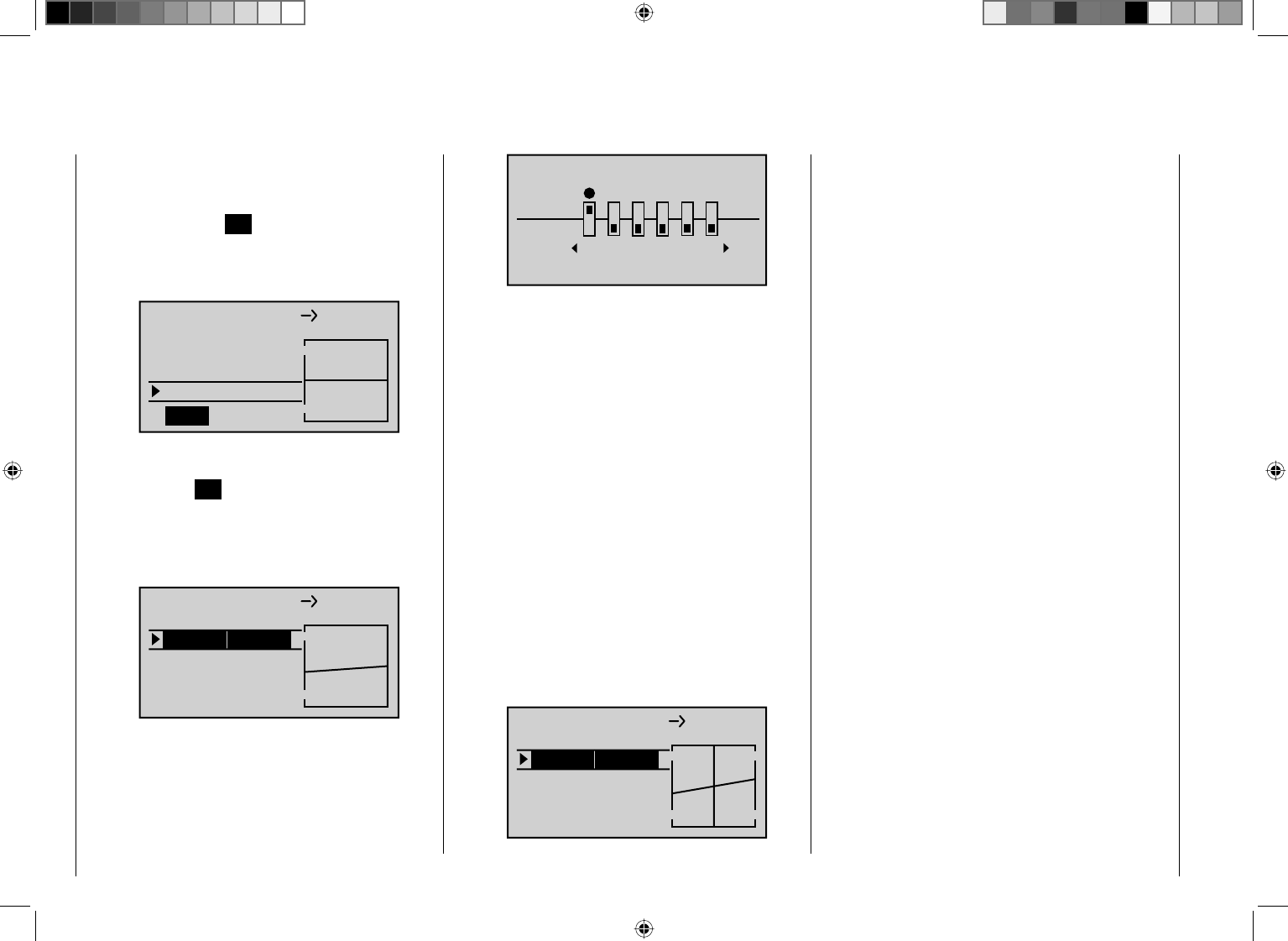
190 Detail program description - Control adjust
… to the mixer confi guration page.
On this page, use the arrow key d on the left or
right touch pad to select the line under "Offset" and
then tap the center SET key on the right touch pad.
Depending on the travel adjustment selected on the
"Control adjust" menu and the switch position, the
offset value jumps to +X% or -X%, e. g.:
L.MIX 4
0% 0%
+100%
Offset
SET
STO
SEL
Mix input
Now use the arrow c key on the left or right touch
pad to move to the line under "Mix input" and then
tap the center SET key on the right touch pad. The
value fi elds are now highlighted. After you have
moved the selected switch to the mixer ON position,
use the arrow keys on the right touch pad to set the
required symmetrical mixer ratio.
L.MIX 1
+100%
Offset
ASY
SYM
6EL
Mix input
+10% +10%
If you have a multi- fl ap wing featuring a "crow or 2.
butterfl y system" with (additional) airbrakes, and you
wish to test the effect of this braking system with and
without airbrakes, then you should simply set channel
1 to "MIX-only" …
MIX ONLY CHANNEL
only
normal
123456
… and follow this by programming a free mixer "C1
¼ C1", so as to restore your ability to control the
airbrakes via servo 1. If you also assign a switch to
this mixer, then you will be able to switch this mixer
on and off as you please.
The fi nal example applies to model helicopters:3.
In the helicopter program, if you wish to assign
collective pitch trim via one of the CTRL 6 … 8
proportional rotary controls, use the "Control
adjust" menu to assign one of these transmitter
controls to (e.g.) "Input 9". (Leave the default value
of "GL" in the "Type" column alone, however, to
confi gure this setting globally for all fl ight phases
– as will be the case for the free mixer yet to be
programmed. Finally, you then simply defi ne a free
mixer "9 ¼ 11" with a symmetrical mixer ratio of e. g.
25%. Due to the internal coupling, this transmitter
control then acts equally on all of the model's
collective pitch servos without affecting the throttle
servo.
L.MIX 1
0%
Offset
ASY
SYM
9 1
Mix input
+25% +25%
Decouple the assigned transmitter control from
control channel 9 on the "MIX-only channel" menu,
however, to ensure that any servo connected to
receiver output 9 can no longer be operated by this
transmitter control; see also page 193.

191
Detail program description - Control adjust
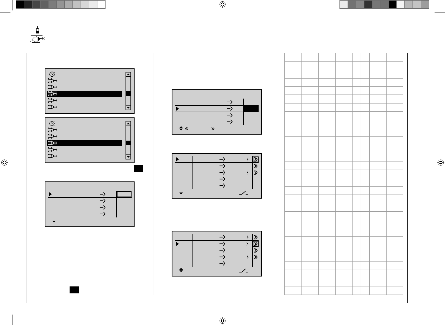
192 Detail program description - Control adjust
MIX active/phase
Selecting mixers for fl ight phases
Using the arrow keys on the left or right touch pad, page
to the menu option …
Fl. phase timers
Wing mixers
MIX-only channel
Dual mixer
Free mixers
MIX active/phase
Helicopter mixer
Fl. phase timers
MIX-only channel
Dual mixer
Free mixers
MIX active/phase
… on the multi-function list. Briefl y tap the center SET
key on the right touch pad to open this menu option.
LinearM1
LinearM2
LinearM3
6EL
C1 EL
LinearM4
3 8
SEL
yes
SEL
yes
yes
yes
MIX ACTIVE IN PHASE
normal
The "free mixers" on the previous menu can be enabled
and disabled for specifi c fl ight phases. You therefore
have complete freedom in assigning specifi c mixers only
to specifi c fl ight phases.
Switch to your chosen fl ight phase and use the arrow
keys to page through this menu. The mixers on the
"Free mixers" menu are displayed in the center column.
Following the activation of the value fi eld by briefl y
tapping the center SET key on the right touch pad, if the
respective mixer is set to "--" by using the arrow keys on
the left or right touch pad, then this mixer is deactivated
in the fl ight phase shown at the bottom of the display
and, simultaneously, removed from the list on the "Free
mixers" menu:
LinearM1
LinearM2
LinearM3
6
LinearM4
3 8
S
SEL
Speed
–––
EL
C1 EL
EL
yes
yes
yes
MIX ACTIVE IN PHASE
If you "lose" a mixer in this way from the "Free mixers"
menu …
ty fr to
M1
M3
6EL
M4
M5
3 8
SEL
?? ??
4
2
M6 ?? ??
… then you should either switch through the fl ight
phases until it appears again … or, alternatively, switch
to this menu and temporarily reactivate the mixer you
are looking for:
ty fr to
M1
M2
M3
6EL
C1 EL
M4
M5
3 8
SEL
?? ??
Tr C4
4
2
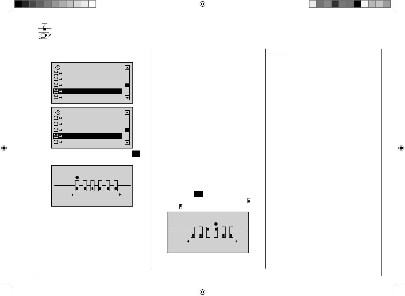
193
Detail program description - Control adjust
MIX-only channel
Separating control functions from control channels for all fl ight phases
Using the arrow keys on the left or right touch pad, page
to the menu option …
Fl. phase timer
Wing mixers
Dual mixer
Free mixers
MIX active/phase
MIX-only channel
Fl. phase timer
Helicopter mixer
Dual mixer
Free mixers
MIX active/phase
MIX-only channel
… on the multi-function list. Briefl y tap the center SET
key on the right touch pad to open this menu option.
MIX ONLY CHANNEL
only
normal
123456
On this menu, you can interrupt the normal signal fl ow
between the control function on the input side and the
control channel on the output side: the "traditional"
transmitter control/servo connection no longer applies.
One particular use of the options offered by this fl ight
phase-independent menu might to reliably keep one of
the control channels "free" in all fl ight phases, as these
control channels can be assigned a transmitter control
or switch for specifi c fl ight phases on the " Control
adjust " menu.
Conversely, a joystick, transmitter control (CTRL 6 …
10) or switch (SW 1 … 3, 8 and 9) "robbed" of its servo
in this way can of course be used anywhere else as a
transmitter control – even in a fl ight phase-specifi c way.
See the programming examples to the right and on
pages 255 and 266.
A joystick, transmitter control (CTRL 6 … 10) or switch
(SW 1 … 3, 8 and 9) robbed of its servo by setting the
channel to "MIX only" will then namely affect mixer
inputs only …
… and the servo connected to a channel set to "MIX
only" is then also only accessible from the mixers
programmed to its control channel, i.e. "(with) MIX(ers)
only".
Accordingly, for any channel set to "MIX only", you can
utilize both its control function and its control channel
entirely independently of one another for any special
functions you need; see the examples at the end of this
section.
Use the arrow keys on the left or right touch pad to
select the desired channel from 1 to 12 (z) and then
briefl y tap the center SET key on the right touch pad,
so as to switch as you please between "normal" ( ) and
"only" mode ( ):
normal
789
10 11 12
MIX ONLY CHANNEL
only
Examples:
For model glider aircraft without airbrakes, the •
butterfl y function (page 160) is generally used as
a landing aid. Just as with "normal" airbrakes, this
is generally controlled using the C1 stick. While the
(airbrakes) servo typically connected to channel 1 is
then generally absent as a rule, receiver output 1 is
still not "free", since the control signal of the brake
stick is still present at this location.
Its control signal – – which in this example is not
required – can be decoupled from control channel
"1", and thus "free up" this channel from the C1 stick
signal, by setting channel 1 to "MIX only" on the
"MIX-only channel" menu. This makes it possible
to use control channel "1", together with receiver
connection "1", at any time for other purposes, via
freely-programmable mixers – e. g. to connect up a
speed controller.
If your model has built-in airbrakes, however, and •
you would like to perhaps test the performance of a
butterfl y system with and without airbrakes, simply
set channel 1 to "MIX only" and program a free mixer
"C1 ¼ C1", so as to restore your ability to control the
airbrakes via servo 1. If you also assign a switch to
this mixer, then you will be able to switch this mixer
on and off as you please.
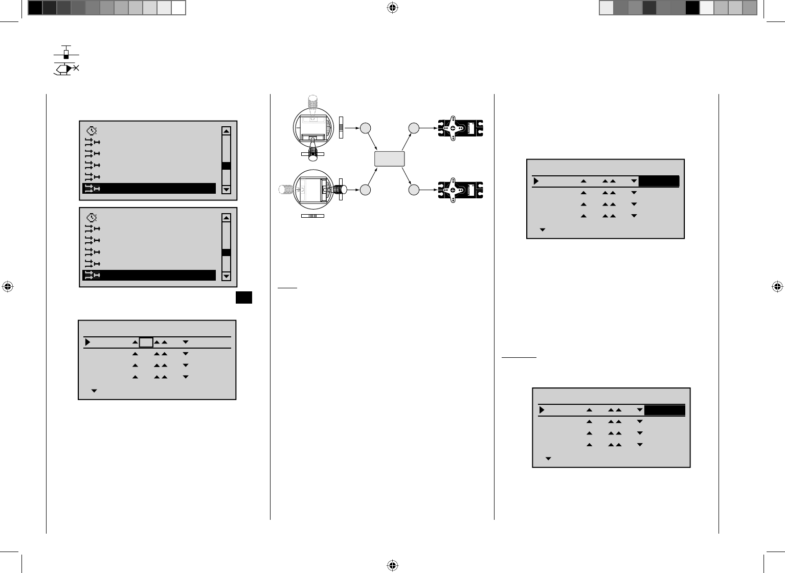
194 Detail program description - Control adjust
Dual mixers
Same-sense/opposite-sense mixing of two control channels
Using the arrow keys on the left or right touch pad, page
to the menu option …
Fl. phase timers
Wing mixers
Free mixers
MIX active/phase
MIX-only channel
Dual mixer
Helicopter mixer
Fl. phase timers
Free mixers
MIX active/phase
MIX-only channel
Dual mixer
… on the multi-function list. Briefl y tap the center SET
key on the right touch pad to open this menu option.
Ty p Diff.
zu
DUAL MIXER
Mixer1
Mixer2
?? ??
Mixer3
Mixer4
?? ??
?? ??
?? ??
0%
0%
0%
0%
Similarly to a V-tail mixer, the four fl ight phase-
independent dual mixers couple …
33
4
Servo 4,8 V
C 577
Best.-Nr. 4101
Servo 4,8 V
C 577
Best.-Nr. 4101
4
V-tail mixer
Control function inputs
Control channels
(receiver outputs)
Elevator stick
Rudder stick
Right rudder / elevat
o
Left rudder / elevato
r
Rudder
Elevator
Elevator
Rudder
Rudder
Elevator
… a same-sense "cc" and an opposite-sense "c
d" control function, although they permit any channel
to be used and offer differential travel for the opposing
function.
Note:
The symbols "cc " and "cd" indicate that the
corresponding inputs act upon the two servos coupled
by the mixer in the same and opposed directions
respectively – they do not indicate the servos' direction
of rotation! Accordingly, if wing fl aps are defl ected in
the wrong direction, simply swap the two inputs around
or use the servo reverse function from the "Servo
adjustments" menu; see page 90.
In the software, the V-tail mixer already mentioned is
supplemented by other "dual mixers" for the two aileron
servos at receiver outputs 2 and 5 and for the fl ap pairs
at outputs 6 and 7 (and 9 and 10 plus 11 and 12, if
present). These are activated via the aileron stick and
the transmitter control that has been assigned to input
"6" on the "Control adjust" menu.
In the same way, the four freely-programmable dual
mixers on this menu can be used to couple two further
control functions, a feature that would otherwise only
be possible with time-consuming programming of free
mixers.
Here, we will use a "V-tail with rudder differential" as
our example to explain the programming of a dual mixer
(see also the example on page 255):
Ty p Diff.
zu
Mixer1
Mixer2
EL
Mixer3
Mixer4
?? ??
?? ??
?? ??
0%
0%
0%
RU +25%
DUAL MIXER
Depending on activation, both servos operate either as
elevators or rudders. Differential travel is effective only
when a rudder command is given, in accordance with
dual mixer assignment. In this case, both associated
trim levers are effective. No additional free mixers are
required for this arrangement. When using this mixer,
however, the tail type MUST be entered as "normal"
on the "Model type" menu.
Example:
Model with two rudders, with differential travel and
outward movement (e. g. swept-back fl ying wing):
Ty p Diff.
zu
Mixer1
Mixer2
8
Mixer3
Mixer4
?? ??
?? ??
?? ??
0%
0%
0%
RU +75%
DUAL MIXER
When a rudder command is given, the second servo
connected to output 8 follows suit. (With this type of
programming, differential travel can be confi gured for
the rudders.) In this case, too, trim from the rudder stick

195
Detail program description - Control adjust
affects both servos. If the rudders are also required to
defl ect outwards when the airbrakes are activated, then
you should assign the C1 stick (transmitter control 1) to
input 8 on the "Control adjust" menu. Finally, move to
the "Offset" column and adjust the offset value until both
rudders return to the neutral position. You may also need
to "play" a little with the offset and travel adjustment
settings.
Tip:
You can use the "Servoanzeige" menu to check
all of the settings made in this way. This menu
can be accessed from almost any other menu by
simultaneously pressing the ef keys on the left touch
pad.
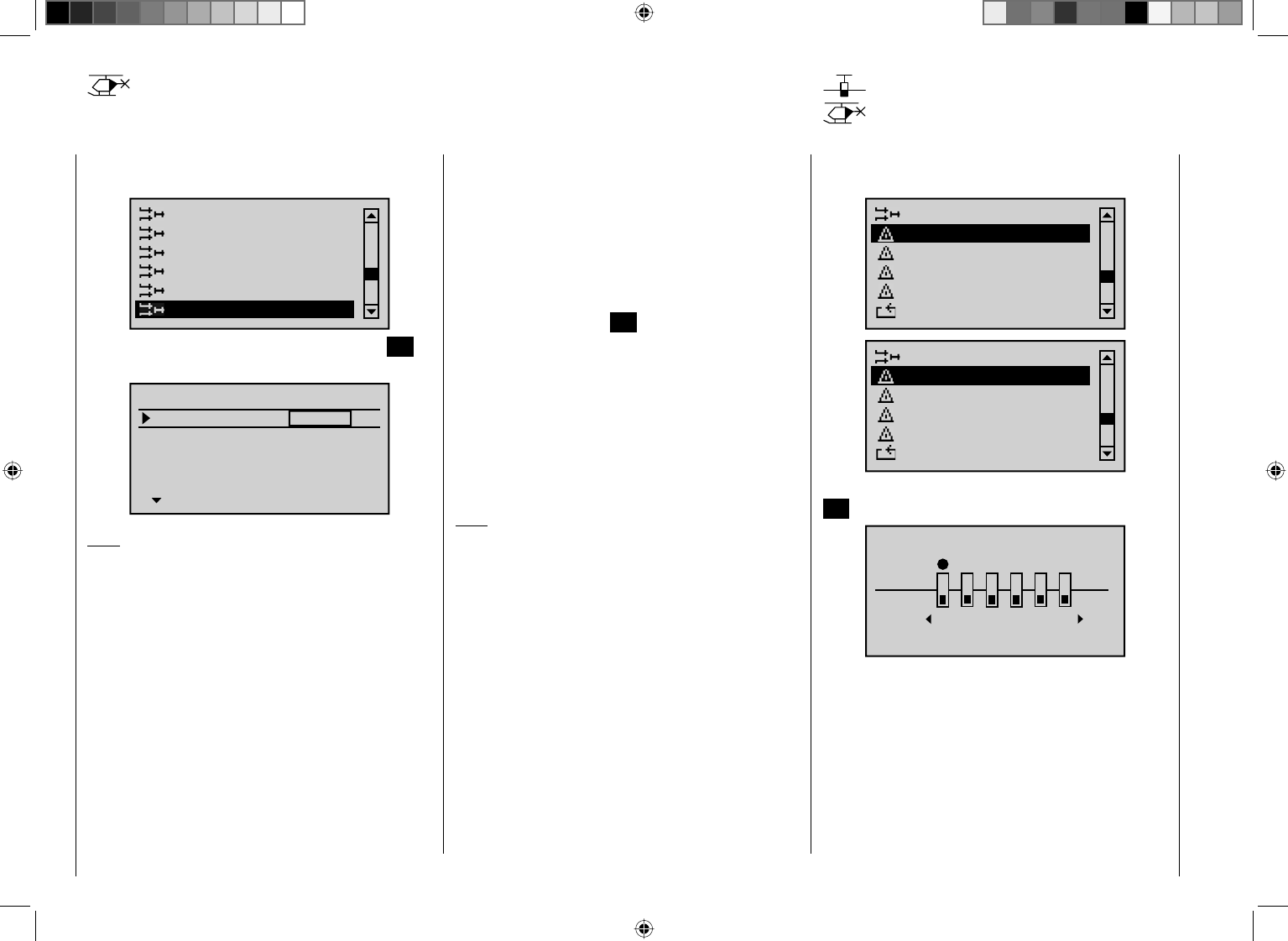
196 Detail program description - Control adjust
Using the arrow keys on the left or right touch pad, page
to the menu option …
Helicopter mixer
Free mixers
MIX active/phase
MIX-only channel
Dual mixer
Swaschplate mixer
… on the multi-function list. Briefl y tap the center SET
key on the right touch pad to open this menu option:
SWASH MIXER
Pitch
Roll
Nick
+61%
+61%
+61%
SEL
Note:
If "1 servo" is selected on the "Swashplate" line on the
"Helicopter type" menu, this option is not shown on the
multi-function list.
On the "Swashplate" line on the "Helicopter type"
menu, you have already defi ned the number of servos
that are installed in your helicopter for collective pitch
control; see page 86. This information is used to
automatically couple together the functions for roll,
pitch-axis and collective pitch, so that you do not need
to defi ne any other mixers yourself.
If you have a model helicopter which only has a single
collective pitch servo, this "Swashplate mixer" menu
option is of course superfl uous, since the software
will control the three swashplate servos for collective
Swashplate mixer
Collective pitch, roll, pitch-axis mixer
pitch, pitch-axis and roll independently of one other,
i.e. without a mixer. In this scenario, this menu
option is therefore no longer available to you from the
multi-function list. With all other swashplate linkages
employing 2 … 4 collective pitch servos, the mixer ratios
and directions are set up by default, as can be seen
above. The preset is +61% in each case, but the value
can be varied from -100% to +100% if required, by
briefl y tapping the center SET key on the right touch pad
and using the arrow keys.
Simultaneously tapping the two arrow keys cd or ef
on the right touch pad (CLEAR) will reset the mixer ratio
in the highlighted fi eld back to its default value of +61%.
If the swashplate control system (collective pitch,
roll and pitch-axis) does not respond to the joysticks
properly, you should alter the mixer directions ("+" or "-")
before trying to correct the directions of servo rotation.
Note:
Ensure that changed mixer values do not result in the
servos mechanically striking their end-stops.
Using the arrow keys on the left or right touch pad, page
to the menu option …
Dual mixer
Teacher / pupil
Tx. output swap
Telemetry
Basic settings
Fail-safe adjust
Swashplate mixer
Teacher / pupil
Tx. output swap
Telemetry
Basic settings
Fail-safe adjust
… on the multi-function list. By briefl y pressing the central
SET key of the right touch pad, this menu item opens:
FAIL SAFE
Pos
hold
123456
DELAY : 0.25s STO
The higher level of operating safety exhibited by the
HoTT system when compared to traditional PPM
technology results from the fact that the microprocessor
built into the HoTT receiver not only exclusively
processes the signals of "its" transmitter, but can
also clean up "dirty" control signals that it receives.
Only when these signals become too error-prone or
garbled due to outside interference does the processor
automatically replace the disrupted signals with the
Fail-safe
197
Detail program description - Control adjust
last received correct signal, temporarily stored in the
receiver. This feature is confi gured by the settings as
described below. This feature also suppresses brief
interference caused by e. g. local drops in fi eld strength,
which otherwise result in the familiar "glitches". In this
case, the red LED lights up on the receiver.
If you have selected a PCM transmission mode for the
active model memory but have not yet carried out the
fail-safe programming, you will see a warning message
on the screen when you switch on the transmitter:
Fail Safe
setup
t.b.d.
Programming procedure
The "Fail Safe" function determines the behavior of the
receiver if communication between the transmitter and
the receiver is disrupted. Receiver outputs 1 … 12 can
optionally …
preserve the current position ("hold"):1.
if communication is disrupted, all servos programmed
to "hold" mode remain at the positions judged to
be the last valid positions by the receiver until the
receiver picks up another valid control signal, or
move to a freely selectable position ("Pos") if 2.
interference should occur, following the expiry of the
"time delay".
Use the arrow keys ef on the left or right touch pad
to select the desired servo connection from 1 to 12 (z)
and then briefl y tap the center SET key on the right touch
pad, so as to switch as you please between the "hold"
() and "Pos" mode ( ):
123456
STO
FAIL SAFE
Pos
hold
DELAY : 0.25s
Following this, use the arrow keys ef on the left or
right touch pad to select the "DELAY" option shown at
the bottom of the display …
789
10 11 12
STO
FAIL SAFE
Pos
hold
DELAY : 0.25s
… and then briefl y tap the center SET key on the right
touch pad. Now use the touch pad's arrow keys to make
your choice from the four possible time delays (0.25 s,
0.5 s, 0.75 s and 1 s) offered.
Simultaneously tapping the arrow keys cd or ef on
the right touch pad (CLEAR) ) will reset the highlighted
fi eld back to its default value of 0.25 s.
Following this, use the arrow keys ef on the left
or right touch pad to select the STO fi eld at the
bottom right of the screen. Then, use the associated
transmitter controls to move the servos, which you have
switched to position mode, into the desired positions
SIMULTANEOUSLY.
Briefl y tap the center SET key on the right touch pad
to store these positions as the fail-safe setting for the
receiver, so that it can revert back to them if interference
is experienced.
Successful storage of the positions is confi rmed briefl y
on the screen:
789
10 11 12
STO
Position
stored
FAIL SAFE
Pos
hold
DELAY : 0.25s
Caution:
Ensure you make use of this safety net by at least
programming the following for a fail-safe incident:
for glow-powered models, set the motor throttle
position to idle; for electric models, set the motor
function to stop, or "Hold" for heli models. If
interference should occur, the model is then less
likely to fl y off on its own and cause damage to
property or even personal injury. Consider asking an
experienced pilot for advice.
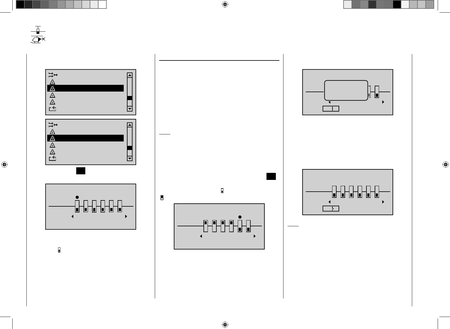
198 Detail program description - Control adjust
Teacher/pupil
Connecting two transmitters for trainer mode with a trainer lead
Using the arrow keys on the left or right touch pad, page to
the menu option "Teacher/pupil" on the multi-function list:
Dual mixer
Tx. output swap
Telemetry
Basic settings
Fail-Safe adjust
Teacher / pupil
Swaschplate mixer
Tx. output swap
Telemetry
Basic settings
Fail-Safe adjust
Teacher / pupil
Briefl y tap the center SET key on the right touch pad to
open this menu option:
TRAINER /Pupil
Pupil
Teach
2345
BIND:SW: –––
1
n/a
6
The screen image shown above shows the menu in its
initial state: No transmitter controls have been released
by the pupil ( ) and no switch is assigned ("SW: ---"
bottom left in the screen image).
Teacher-pupil settings
Up to twelve control functions of the teacher transmitter
"Teach" can be transferred to the pupil transmitter
"Pupil", either individually or in any combination.
The lower display line, named "Teach", therefore refers
to the transmitter controls permanently connected
to inputs 1 … 4 (dual axis stick functions for fi xed-wing
and heli model) and the CTRL 6 to 10 controls that are
assigned or can be assigned to inputs 5 … 12 (optionally
fl ight phase-specifi c) on the "Control adjust" menu.
Note:
The assignment of transmitter controls on the "Control
adjust" menu is possible only when the trainer mode
connection is inactive.
Use the arrow keys ef on the left or right touch pad
to select the transmitter controls from 1 to 12 (z) to
transfer to the pupil and then briefl y tap the center SET
key on the right touch pad in each case, so as to switch
between "Teach" (Teacher)" ( ) and "Pupil"
():
2345
BIND:SW: –––
16
TRAINER /Pupil
Pupil
Teach
n/a
To be able to carry out the transfer, you must then
assign a trainer mode switch on the left of the display.
To do so, use the arrow keys on the left or right touch
pad to move the marker to the bottom left, to the right of
"SW:" Here, assign a switch as described on page 52.
Preferably, you should utilize one of the two momentary
switches, SW 1 or SW 9, so as to be able to revert
control back to the teacher transmitter at any time.
89
10
BIND:SW:
7
9
11 12
TRAINER /Pupil
Pupil
Teach
n/a
No
pupil
signal
Since at this early stage of programming a trainer
system it is unlikely that an operational pupil transmitter
is connected to the teacher transmitter, the transmitter
responds immediately to the switches closed during the
switch assignment process with appropriate visual and
audible warning notices.You should therefore re-open
the switch you have just assigned:
89
10
BIND:SW:
7
9
Ä
11 12
TRAINER /Teach
Pupil
Teach
n/a
Note:
The switch assignment just described also determines
the transmitter used to issue the teacher and pupil
functions, respectively
. For this reason, a pupil
transmitter must NEVER be assigned a switch on this
menu. The header line therefore also switches from
"TRAINER /Pupil" to "TRAINER /Teach" once a
switch has been assigned.
The model to be controlled by the pupil must be
programmed completely – i. e. with all its functions
including trims and any mixer functions – in one of
199
Detail program description - Control adjust
the model memories of the mc-32 HoTT teacher
transmitter. The HoTT receiver of the model in question
must also be "bound" to the teacher transmitter, since the
latter ultimately controls the model, even in pupil mode.
ALWAYS ENSURE YOU SWITCH ON THE mc-32
HoTT teacher transmitter FIRST BEFORE PLUGGING
THE CONNECTION CABLE INTO THIS UNIT. If you do
not, the RF module will not be enabled.
The mc-32 HoTT teacher transmitter can be
connected to any suitable pupil transmitter, even
transmitters using the "traditional" 35/40 MHz range.
If the pupil-side connection does NOT utilize a two-
pole DSC socket, however, but a three-pole trainer
socket from the Graupner range (for example), then the
fundamental precondition for a correct connection
to a pupil transmitter is that the modulation type
PPM (18 or 24) must ALWAYS be confi gured in the
pupil transmitter, regardless of the modulation type
used in the teacher transmitter.
Pupil transmitter set-up
The model to be controlled by the pupil must be
programmed completely – i. e. with all its functions including
trims and any mixer functions – in one of the model
memories of the teacher transmitter. If present, the HoTT
receiver of the model in question must also be "bound" to
the teacher transmitter. In principle, however, an mc-32
HoTT pupil transmitter can also be connected to a teacher
transmitter from the "traditional" 35/40 MHz range.
Almost any transmitter with at least 4 control functions
from previous and current Graupner series can be used
as a pupil transmitter. More detailed information can be
found in the RC main catalog and on the www.graupner.
de website.
If required, the pupil transmitter should be fi tted with the
connection module for pupil transmitters. This is to be
connected to the transmitter board in accordance with
the supplied installation instructions.
Information on the pupil modules required in each case
can be found in Graupner's RC main catalog and on the
www.graupner.de website.
The connection to the teacher transmitter is made using
the appropriate lead; see the following double page.
The control functions of the pupil transmitter MUST
act directly on the control channels, i. e. the receiver
outputs, without intermediary mixers.
If you are using an "mc" or "mx" series transmitter,
it is best to activate a free model memory with the
required model type ("Fixed-wing" or "Heli"). Assign the
model name "Pupil" and set up the stick mode (mode 1
… 4) and "Throttle min. forward/back" to suit the pupil's
preferences. All other settings are left at their default
values, however. If you have selected the "Helicopter"
model type, you must also set the throttle/ collective
pitch direction and idle trim on the pupil transmitter. All
other settings, including mixer and coupling functions,
are confi gured exclusively on the teacher transmitter,
which in turn transmits them to the model.
With "D" and "FM" type transmitters, you must also
check the direction of servo rotation and stick mode,
and adjust as necessary by swapping the corresponding
leads. All mixers must also be switched off or set to
"zero".
When assigning control functions, the usual conventions
must be observed:
Channel Function
1 Motor throttle/collective pitch
2 Aileron/roll
3 Elevator/pitch-axis
4 Rudder/tail rotor
If you wish to transfer other control functions to the pupil
transmitter in addition to the functions of the two dual
axis sticks (1 … 4), access the "Control adjust" menu
on the pupil transmitter and assign transmitter controls to
the inputs that correspond to the control numbers 5 … 12
released on the teacher transmitter's "Teacher/pupil" menu.
Important:
If you should forget to assign a transmitter •
control on the pupil side, then the affected servo
or servos will remain in the center position when
the transfer is made to the pupil transmitter.
The pupil transmitter must always be operated in •
PPM mode, regardless of the RF connection type
used between the teacher transmitter and the model.
If the transmitter is connected using a DSC •
socket on the pupil side, ALWAYS leave the
pupil transmitter's On/Off switch in the "OFF"
position: this is the only way to guarantee that
no RF signal is sent from the pupil transmitter's
transmitter module , even after the DSC lead has
been plugged in.
Trainer mode operations
Both transmitters are connected to one another using
a suitable lead (see summary on next page): The plug
marked "M" (master) must be inserted into the socket
on the teacher transmitter, and the plug marked "S"
(student) into the pupil transmitter's socket. (Note that
not all leads may have such "M" and "S" labeling.)
200 Detail program description - Control adjust
Important notices:
Check that the model aircraft is operational •
and check that all functions issue the correct
commands BEFORE setting up trainer mode.
The ends of the trainer lead, usually marked as •
either "S" or "M", terminate in a three-pole TRS
jack. Do not insert these jacks into a DSC system
socket, as it is not suitable for this application.
The DSC socket is exclusively designed for a
trainer lead with 2-pole TRS jacks.
Checking functionality
Activate the assigned trainer mode switch:
The trainer mode system is working properly if the •
display now changes from "¾Teach" to "¾Pupil".
If the center LED rapidly fl ashes blue/red, however, •
and the unit beeps at the same time, then the pupil-
teacher transmitter connection has been lost.
The basic display also displays the following warning
notice …
No
pupil
signal
… and the left side of the screen display on the
"Teacher/pupil" menu changes to show "-Pupil".
In this case, all control functions are retained by
the teacher transmitter automatically, regardless of
switch position: this ensures the model is always
under control.
Possible faults:
Pupil transmitter not ready•
Interface in pupil transmitter not correctly connected •
in place of the RF module
Cables connected wrongly: see right for cable •
connections
Pupil transmitter not switched over to PPM (10, 18, •
24) mode
Other possible faults:
Teacher transmitter not properly "bound" to HoTT •
receiver in training model
Trainer leads
4179.1 For trainer mode operation between any two
Graupner transmitters equipped with a DSC
socket (identifi able by the two-pole TRS
jacks at each end of the lead)
3290.7 Trainer lead for connecting a teacher
transmitter with DSC socket (e. g. mc-32
HoTT) or a transmitter retrofi tted with the
optional DSC module, order no. 3290.24)
) to a Graupner pupil transmitter with an
optoelectronic pupil socket (identifi able by
the label "S" on the end with the three-pole
TRS jack).
3290.8 Trainer lead for connecting a pupil
transmitter with DSC socket (e. g. mc-32
HoTT) or a transmitter retrofi tted with the
optional DSC module, order no. 3290.24)
to a Graupner teacher transmitter with an
optoelectronic teacher socket (identifi able by
the label "M" on the end with the three-pole
TRS jack).
For further details about the cables and modules for
teacher and pupil transmitters mentioned in this section,
please consult the respective transmitter handbook,
the Graupner RC main catalog or the www.graupner.de
website.
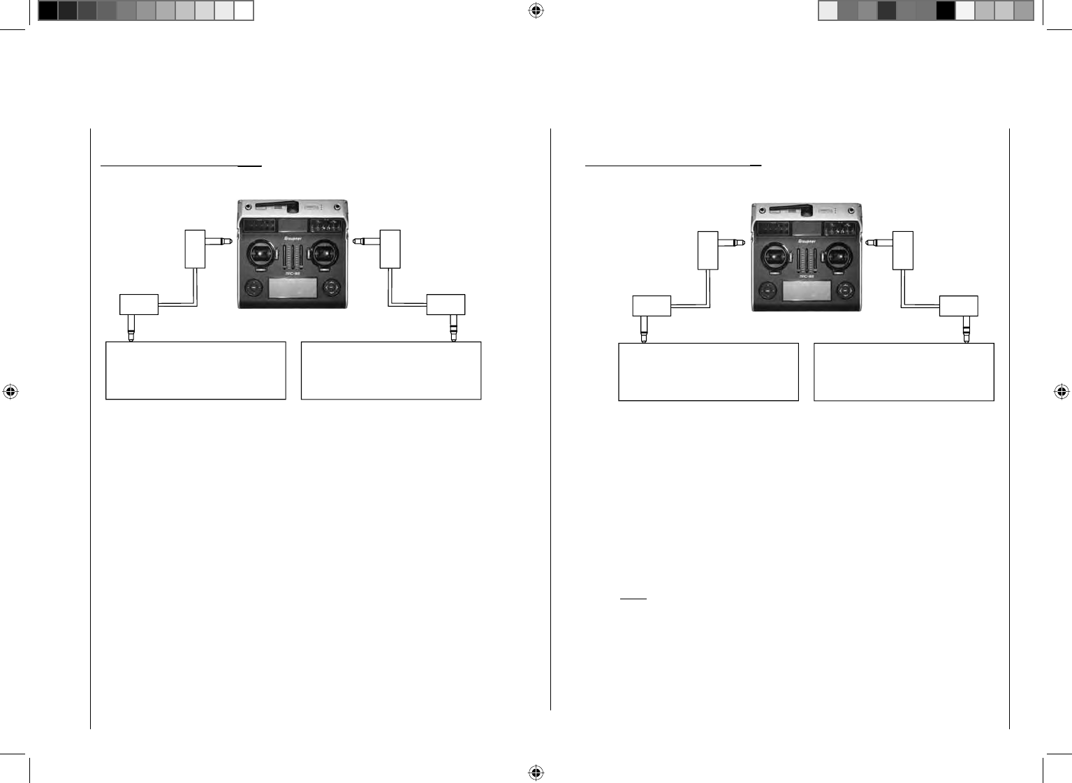
201
Detail program description - Control adjust
Trainer mode with the mc-32 transmitter
Due to the continuous improvements made to the product range, please consult our website at www.graupner.de for the latest information
Teacher transmitter
with DSC socket
Teacher transmitter with teacher
module order no.
3290.2,3290.19,3290.22
Trainer lead
order no. 4179.1
Trainer lead
order no. 3290.8
M
Pupil transmitter mc-32 HoTT
mx-12 HoTT, mx-16 HoTT,
mc-32 HoTT
mc-19(s, iFS + HoTT) up to
mc-24,mx-22(iFS), mx-24s
Pupil transmitter
with DSC socket
Pupil transmitter with pupil module
order no. 3290.3,3290.10,3290.33
Trainer lead
order no. 4179.1
Trainer lead
order no. 3290.7
D 14, FM 414, FM 4014, FM
6014, mc-10 … mc-24,mx-
22(iFS), mx-24s
S
Teacher transmitter mc-32 HoTT
mx-12(s)HoTT, mx-16s/
iFS/HoTT, mc-32 HoTT,
mx-22(iFS), mx-24s and, if
equipped with DSC socket order
no. 3290.24,mc-19(s + iFS),
mc-22(s + iFS) and mc-24
Note:
The lists present the possible transmitters/transmitter
combinations at the time of going to press.
HoTT TT
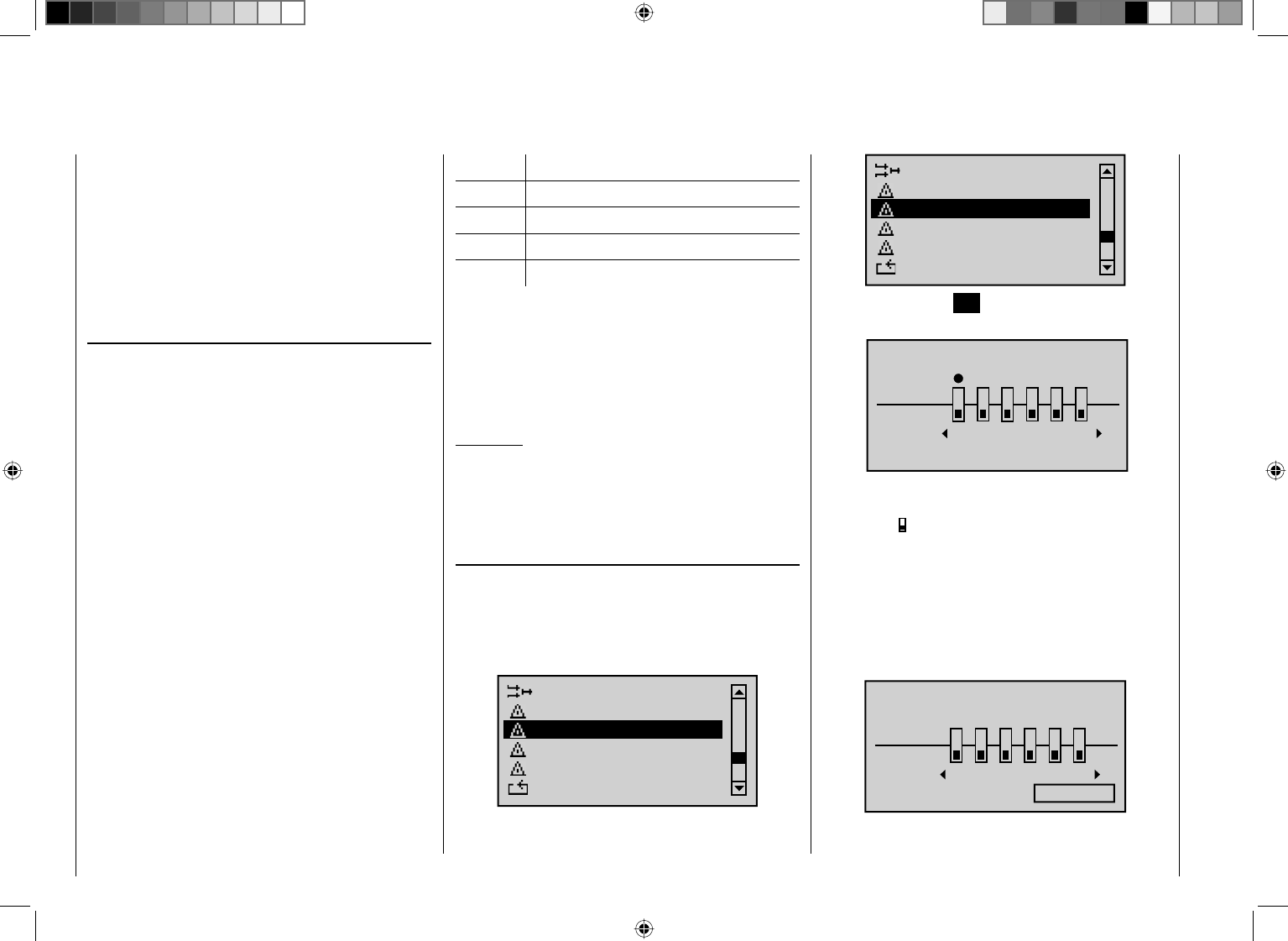
202 Detail program description - Control adjust
Wireless HoTT system
The mc-32 HoTT trainer mode system can also be
operated wirelessly. To do so, the teacher transmitter
must be "connected" to a pupil transmitter as described
below. Prior to this, however, the training model's
receiver must be bound to the PUPIL transmitter. This
confi guration is possible between transmitters that have
the "BIND:" option available on the "Teacher/pupil"
menu.
Preparing for training mode
Teacher transmitter
The training model must be programmed completely –
i. e. with all its functions including trims and any mixer
functions – in one of the model memories of the HoTT
teacher transmitter. The model to be used for training
must therefore be under the complete control of the
teacher transmitter. The fi nal step in preparation,
however, is to bind the training model to the pupil
transmitter. For a detailed description of the bind
procedure, please consult pages 69 and 74.
Pupil transmitter
If you are using an "mc" or "mx" series transmitter,
it is best to activate a free model memory with the
required model type ("Fixed-wing" or "Heli"). Assign the
model name "Pupil" and set up the stick mode (mode
1 … 4) and "Throttle (or collective pitch) min. forward/
back" to suit the pupil's preferences. All other options are
left at their default values. All other settings, including all
mixer and coupling functions, are confi gured exclusively
on the teacher transmitter, which in turn transmits them
to the model.
When assigning control functions, the usual conventions
must be observed:
Channel Function
1 Motor throttle/collective pitch
2 Aileron/roll
3 Elevator/pitch-axis
4 Rudder/tail rotor
If you wish to transfer other control functions to the pupil
transmitter in addition to the functions of the two dual
axis sticks (1 … 4), access the "Control adjust" menu
on the pupil transmitter and assign transmitter controls to
the inputs that correspond to the control numbers 5 … 12
released on the teacher transmitter's "Teacher/pupil" menu.
Important:
If you should forget to assign a transmitter control
on the pupil side, then the affected servo or servos
will remain in the center position when the transfer
is made to the pupil transmitter.
Preparing the teacher and pupil transmitters
Once you have bound the training model to the pupil
transmitter, now switch on the teacher transmitter. On
both transmitters, use the arrow keys on the left or right
touch pad, page to the "Teacher/pupil" menu option on
the multi-function list:
Dual mixer
Tx. output swap
Telemetry
Basic settings
Fail-Safe adjust
Teacher / pupil
Swaschplate mixer
Tx. output swap
Telemetry
Basic settings
Fail-Safe adjust
Teacher / pupil
Briefl y tap the center SET key on the right touch pad to
open this menu option:
TRAINER /Pupil
Pupil
Teach
2345
BIND:SW: –––
1
n/a
6
The screen image shown above shows the menu in its
initial state: No transmitter controls have been released
to the pupil ( ) and no switch is assigned ("SW: ---"
bottom left in the screen image).
Pupil transmitter
Using the arrow keys on the left or right touch pad, move
the marker frame to the "BIND" input fi eld. If you can
see a switch to the right of "SW:", then this MUST fi rst
be erased, see screen image:
2345
BIND:SW: –––
16
TRAINER /Pupil
Pupil
Teach
n/a
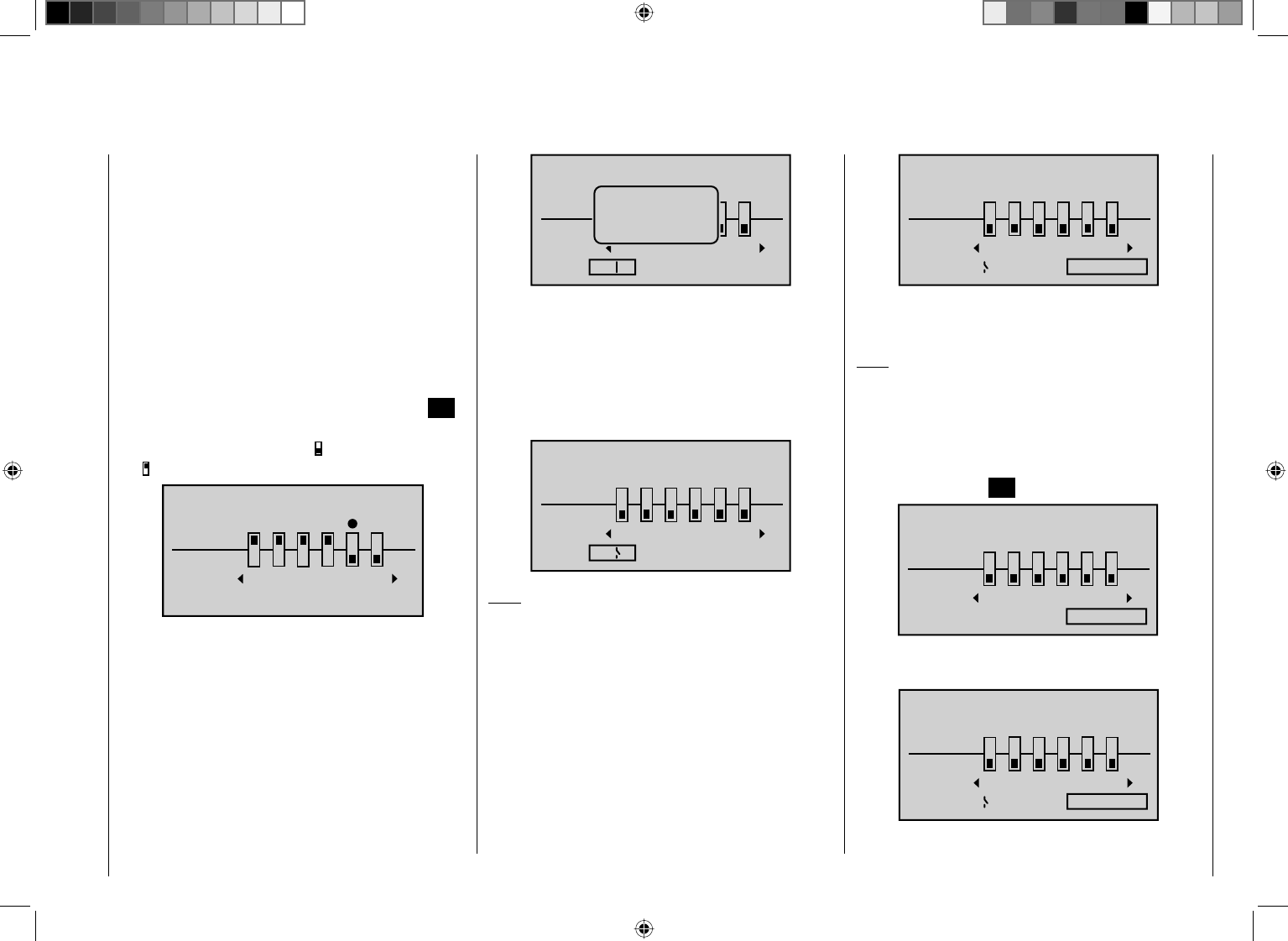
203
Detail program description - Control adjust
Teacher transmitter
Up to twelve control functions of the teacher transmitter
"Teach" can be transferred to the pupil transmitter
"Pupil", either individually or in any combination.
The lower display line, named "Teach", therefore refers
to the transmitter controls permanently connected
to inputs 1 … 4 (dual axis stick functions for fi xed-wing
and heli model) and the CTRL 6 to 10 controls that are
assigned or can be assigned to inputs 5 … 12 (optionally
fl ight phase-specifi c) on the "Control adjust" menu.
Use the arrow keys ef on the left or right touch pad
to select the transmitter controls from 1 to 12 (z) to
transfer to the pupil and then briefl y tap the center SET
key on the right touch pad in each case, so as to switch
between "Teach" (Teacher)" ( ) and "Pupil"
():
2345
BIND:SW: –––
16
TRAINER /Pupil
Pupil
Teach
n/a
To be able to carry out the transfer, you must now assign
a trainer mode switch. To do so, use the arrow keys on
the left or right touch pad to move the marker frame
to the bottom left, to the right of "SW:" now assign a
switch as described in the section "Assigning transmitter
controls, switches and control switches" (page 52).
Preferably, you should utilize one of the two momentary
switches, SW 1 or SW 9, so as to be able to revert
control back to the teacher transmitter at any time:
89
10
BIND:SW:
7
9
11 12
TRAINER /Pupil
Pupil
Teach
n/a
No
pupil
signal
Since at this stage of programming the wireless trainer
system no connection yet exists to a pupil transmitter,
the transmitter responds immediately to the switches
closed during the switch assignment process with
appropriate visual and audible warning notices. You
should therefore re-open the switch you have just
assigned:
89
10
BIND:SW:
7
9
Ä
11 12
TRAINER /Teach
Pupil
Teach
n/a
Note:
The switch assignment just described also determines
the transmitter used to issue the teacher and pupil
functions, respectively
. For this reason, a pupil
transmitter must NEVER be assigned a switch on this
menu. The header line therefore also switches from
"TRAINER /Pupil" to "TRAINER /Teach" once a
switch has been assigned.
Using the arrow keys on the left or right touch pad, now
move the marker frame to the right, to "BIND: n/a":
89
10
BIND:SW:
7
9
Ä
11 12
TRAINER /Teach
Pupil
Teach
n/a
Binding the pupil transmitter to the teacher
transmitter
Note:
During the bind process, the two transmitters should
not be very far apart. You may fi nd you need to change
the positions of the transmitters and then start the bind
process again.
Initiate the "BINDING" process from the pupil transmitter
by tapping the center SET key on the right touch pad …
89
10
BIND:SW:
7
9
Ä
Binding
–
11 12
TRAINER /Pupil
Pupil
Teach
… and repeat this immediately on the teacher
transmitter:
89
10
BIND:SW:
7
9
Ä
Binding
11 12
TRAINER /Teach
Pupil
Teach
As soon as this process is complete, both screens will
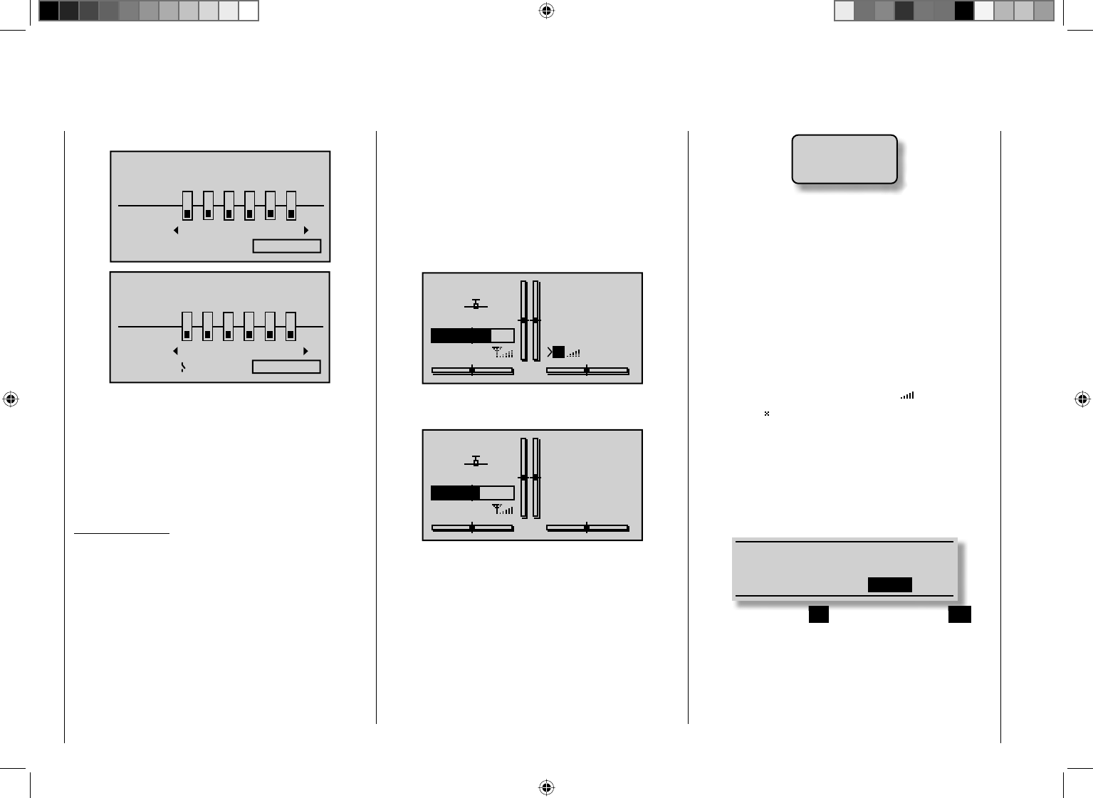
204 Detail program description - Control adjust
show "ON" instead of the fl ashing "BINDING":
89
10
BIND:SW:
7
9
Ä
ON
–
11 12
TRAINER /Pupil
Pupil
Teach
89
10
BIND:SW:
7
9
Ä
ON
11 12
TRAINER /Teach
Pupil
Teach
You can return to the basic display on both screens and
start the training session after carefully checking all of
the relevant functions.
If neither transmitter or only one transmitter displays
"ON", this means the binding process has failed: try
changing the positions of both transmitters and then
repeat the entire procedure.
Important notice:
Check that the model aircraft is operational and
check that all functions issue the correct commands
BEFORE setting up trainer mode.
During the …
Training session
… the teacher and pupil can maintain a more "relaxed"
distance from one another. The "reach of signal"
(max. 50 m) should not be exceeded under any
circumstances, however, nor should anyone else be
standing between the teacher and the pupil, since these
persons could reduce the connection range of the return
channel used by the two transmitters. Furthermore, you
should remember that the return channel assigned for
wireless trainer mode functionality is normally used for
telemetry connections: accordingly, it will not be possible
to transmit any model telemetry data.
In this operating mode, the basic display of the teacher
transmitter is as shown below …
GRAUBELE
#01
2:22h
Stop
Flt
«Normal »
K78
0:00
0:00
5.5V
5.2V
P
HoTT
RF –Teach
… and the pupil transmitter's display will look something
like this:
PUPIL
#01
3:33h
Stop
Flt
«normal »
K78
0:00
0:00
5.5V
4.9VHoTT
RF –Pupil
If, however, the connection between the teacher and
pupil transmitters should be lost during the training
session, then the teacher transmitter will automatically
assume control of the model.
If the trainer mode switch is in the "Pupil" position when
connectivity is lost, then the center LED on the teacher
transmitter will fl ash blue/red while the signal is lost and
audible warning signals will also be given. The basic
display also displays the following warning notice:
No
pupil
signal
If only the character string "HF –" starts fl ashing on
the transmitter's basic display, however, and (quieter)
audible warning signals are given, the pupil signal has
still been lost, but the trainer mode switch is set to the
"Teacher" position.
In both cases, your fi rst step should be to reduce the
distance between the two transmitters. If this does not
help, then you should land immediately and establish
the cause.
If both transmitters are operational and the receiver
system is switched off, then the teacher transmitter's
basic display will show the "familiar" instead of the
t w o i c o n s . The antenna icon will also fl ash and an
audible warning signal will sound twice per second.
Resuming trainer mode
If you switch off one or both transmitters during the
session – for whatever reason – then the basic display
of the transmitter(s) shows the following question after
being switched back on:
Please select
trainer link?
ACT INH
If you either confi rm "INH" by tapping the center SET
key on the right touch pad, or alternatively wait for
approx. two seconds until the message disappears,
then you will reset the transmitter in question back to
its "normal" operating mode. You will then have to re-
establish a connection between the teacher and pupil
transmitters.
205
Detail program description - Control adjust
If, on the other hand, you use the arrow keys on the left
or right touch pad to select "ACT" …
Please selcet
trainer link?
ACT INH
… and confi rm this selection by tapping the center SET
key on the right touch pad, then the existing teacher
connection is restored. The same approach is used if the
transmitter is confi gured as a pupil transmitter.
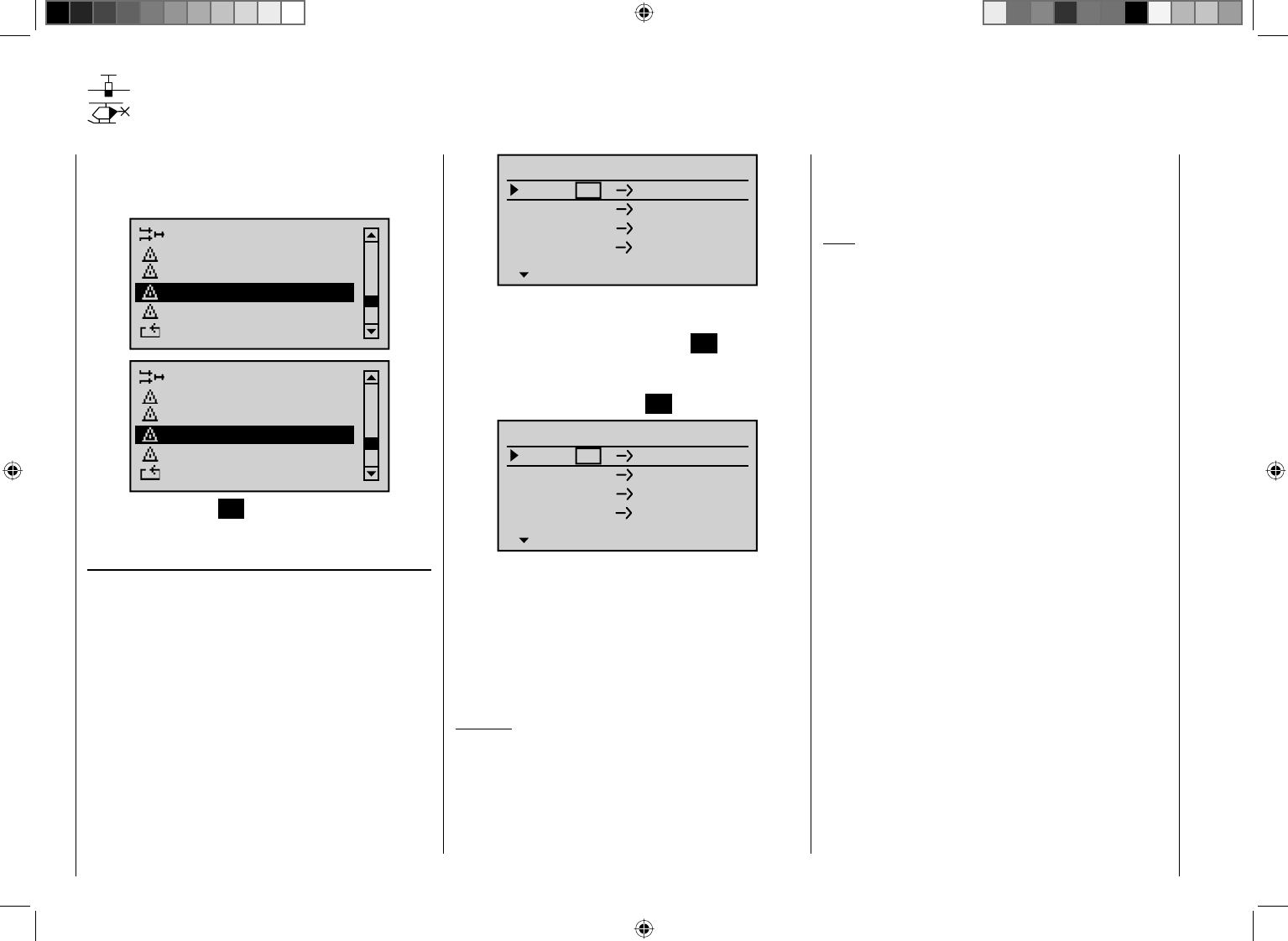
206 Detail program description - Control adjust
Using the arrow keys on the left or right touch pad, page
to the menu option "Tx. output swap" on the multi-
function list:
Dual mixer
Telemetry
Basic settings
Fail-safe adjust
Teacher / Pupil
Tx. output swap
Swashplate mixer
Telemetry
Basic settings
Fail-safe adjust
Teacher / Pupil
Tx. output swap
Briefl y tap the center SET key on the right touch pad to
open this menu option.
Tx. output swap
To achieve maximum fl exibility regarding receiver socket
assignment, the mc-32 HoTT program offers you the
option of swapping servo outputs 1 to 12 as you please.
This option lets you distribute the transmitter's 12
"control channels" to any of the transmitter outputs 1
… 12. If you do, you must remember that the "Servo
display" screen – accessible from almost any menu
option by simultaneously tapping the eand f keys
on the left touch pad – refers exclusively to the "control
channels" as preset by the receiver socket assignment:
it therefore does NOT take any output swaps into
account.
Tx. output swap
Swapping the outputs on the transmitter
Tx Ch
Tx Ch
Tx Ch
Tx Ch
1
2
3
4
1
2
3
4
Output
Output
Output
Output
TRANSMITTER OUTPUT
SEL
Use the arrow keys cd on the left or right touch pad to
select the channel/output combination that you wish to
change and then briefl y tap the center SET key on the
right touch pad. You can now use the right arrow keys
to assign your selected (control) channel to the desired
output, confi rming this with the SET key …
2
3
4
1
2
3
4
SEL
6
Tx Ch
Tx Ch
Tx Ch
Tx Ch
Output
Output
Output
Output
TRANSMITTER OUTPUT
… or, by tapping the arrow keys cd or ef on the
right touch pad at the same time (CLEAR), you can
restore the original assignment.
Any subsequent changes, such as servo travel
adjustments, Dual Rate / Expo, mixers etc., must
always be performed in accordance with the original
receiver socket assignment!
Example:
In the mc-32 HoTT helicopter program, the outputs
for a collective pitch servo and the throttle servo are
swapped around, compared to some older GRAUPNER/
JR mc units. The throttle servo now occupies transmitter
output "6" and the collective pitch servo output "1".
Perhaps, however, you wish to retain the previous
confi guration? In this case, you will swap over channels
1 and 6 as appropriate, so that (control) channel 6 is
located on output 1 and vice versa – as shown above:
Note:
The "Channel Mapping" (channel assignment) function
integrated into the telemetry menu on the
mc-32HoTT receiver can also be used to distribute up
to 12 control channels from the transmitter to multiple
receivers. The function can also be used to map the
exact same control function to multiple receiver outputs:
this can be used to confi gure two servo controls per
aileron surface instead of just the one, for example, etc.
To keep controls manageable, however, we strongly
recommend using only one of the options at a time.

207
Detail program description - Control adjust
208 Detail program description - Control adjust
Telemetry
The transmitter and receiver data as well as the data
for optional telemetric sensors (see Appendix) can be
viewed and programmed in the "Telemetry" menu.
The receiver data is transmitted to the transmitter
through the return channel integrated in the HoTT
receiver.
One telemetry sensor can be connected through the
telemetry input to each of the receivers GR-12S HoTT
(Order No. 33505), GR-12 HoTT (Order. No. 33506),
GR-16 (Order. No. 33508) and GR-24 HoTT (Order. No.
33512).
The corresponding "Telemetry" menus always keep
these and future receivers up to date with the latest
version and ensures enhancement with future functions
or languages.
Note:
After registering your product at https://www.graupner.
de/de/service/produktregistrierung you are automatically
informed of new updates.
Important information:
This manual depicts the available functions at the •
time of printing.
As already indicated in the section "Connection •
of multiple receivers" on page 69 and 74, multiple
receivers can be connected as necessary for each
model. During the later operation, however, only
the receiver which was activated in the line "TEL.
EMPF." of the "Telemetry" menu, is capable
of establishing a telemetric connection to the
transmitter! However, that also means the inverse,
that only this receiver can be addressed through the
Telemetry menu! If necessary, therefore, the selection
must be changed before settings can be made on a
specifi c receiver:
TELEMETRY
SETTING & DATA VIEW
SENSOR SELECT
RF STATUS VIEW
VOICE TRIGGER
TEL.RCV BIND. 1
When adjusting the settings of the remote •
control, make absolutely sure that the transmitter
antenna is always far enough away from the
receiver antennae! To be on the safe side, keep
them at least one meter apart. Otherwise you
run the risk of a faulty connection for the return
channel and malfunction as a result.
Since the telemetric data between transmitter and •
receiver is only exchanged after the fourth data
package, the data transmission requires a certain
amount of time for technical reasons, so the reaction
to the operating keys and changes to settings take
place with a delay. Therefore, the delay is not due to
an error.
Programming on the model or on sensors may only •
take place if the model is on the ground. Only carry
out the settings with the motor switched off and
the battery disconnected! Otherwise, undesired
programming cannot be ruled out.
For example, a servo test initiated accidentally
could cause the model to crash and cause personal
injury and/or property damage. Observe the safety
instructions on pages 4-7 of this manual and the
individual respective manuals.
All settings (such as fail-safe, servo direction •
reversal, servo travel, mixer and curve settings, etc.)
made through the "Telemetry" menu are only saved
in the receiver and, therefore, are adopted along with
it in the course of the conversion of a receiver to a
different model, if applicable. Therefore, to be on the
safe side, re-initialize your HoTT receiver if you want
to use the receiver in a different model; see "Reset"
on page 43.
Only program the servo direction reversal, servo •
travel, mixer and curve settings through the mc-32
specifi c standard menus "Servo adjustment" page
90, "Dual Rate / Expo" page 108 and 112, "Channel
1 curve" page 116 and 119, etc. Otherwise, the
settings superimpose one another, which can lead to
complexity or even problems in the later operation.
With the channel assignment function of the •
Telemetrymenu integrated in the mc-32 HoTT, control
functions can also be assigned with distribution to
multiple receivers or multiple receiver outputs can
even be assigned with the same control function,
such as the ability to activate two servos per aileron
instead of only one individual servo, etc. We also
recommend exercising extreme during the
programming.
209
Detail program description - Control adjust
Telemetry
The menus comprised under the heading "Telemetry"
can be called up from the default display of the
transmitter mc-32 HoTT by pressing the central ESC
key of the left touch pad for approx. one second. The
same menus can, like other menus of the transmitter,
also be opened in the multifunction list by pressing the
central SETkey on the right touch pad:
Dual mixer
Basic settings
Fail-safe adjust
Teacher / pupil
Tx. output swap
Telemetry
Swashplate mixer
Basic settings
Fail-safe adjust
Teacher / pupil
Tx. output swap
Telemetry
Basic operation
The operation of the "Telemetry" is essentially the
same as that of the other menus of the transmitter
mc-32 HoTT. The few differences are described in the
following:
You can switch between the individual pages of the
Telemetry menu with the arrow keys ef of the left
or right touch pad. The corresponding directional
indications can be found at top right of each display
page in the form of angled brackets (<>); see the
following fi gures. If only one angled bracket is visible,
you are on either the fi rst or last respective page. In this
case, changing pages is only possible in the indicated
direction.
Menu lines in which parameters can be changed are
identifi ed with the aforementioned angled bracket (>). By
pressing the arrow keys of the cd of the left or right
tough pad, the ">" pointer jumps one line forward or one
line back. Lines which you cannot jump to cannot be
changed.
In order to change a parameter, briefl y press the
central SET key of the right touch pad (the parameter
is represented inversely), change the value within the
permissible adjustment range with the arrow keys of the
right touch pad and adopt the value by pressing the SET
key again. By briefl y pressing the central ESC key of the
left4-way pad, you return to the starting position.
Now select the desired submenu with the arrow keys
cd of the left or right touch pad. However, if the
message …
CAN‘T
RECEIVE
DATA
OK
… appears instead of the desired submenu after
pressing the central SET key of the right touch
pad, no connection has been established to the
receiver. Therefore, switch on your receiver system
or, if applicable reconnect the addressed receiver as
described on page 68 and 74 or activate it as described
under "Important Notices" on the previous page.
On the fi rst display page of the submenu overwritten
with …
RX DATAVIEW
…
TELEMETRY
SETTING & DATA VIEW
SENSOR SELECT
RF STATUS VIEW
VOICE TRIGGER
TEL.RCV rcv ch1
… no settings can be made. This page is only provided
for information:
RX DATAVIEW
S–STR100% R–TEM.+28°C
L PACK TIME 00010msec
R-VOLT :05.0V
L.R-VOLT:04.5V
S–QUA100%S–dBM–030dBM
SENSOR1 :00.0V 00°C
SENSOR2 :00.0V 00°C
Value Explanation
S-QUA Signal quality in %
S-dBm Reception power in dBm
S-STR Signal strength in %
R-TEM. Receiver temperature in °C
L PACK TIME Indicates the time in ms in which the
longest data package is lost during the
transmission from the transmitter to the
receiver
R-VOLT Current operating voltage of the
receiver in volts
SETTINGS/DISPLAYS
210 Detail program description - Control adjust
L.R-VOLT Lowest operating voltage of the
receiver since it was last turned on, in
volts
SENSOR1 Indicates the values of the optional
telemetric sensor 1 in volts and °C
SENSOR2 Indicates the values of the optional
telemetric sensor 2 in volts and °C
Signal quality (S-QUA)
The signal quality (S-QUA) is sent "live" over the return
channel of the receiver to the transmitter and indicates
the signal strength in %.
Reception power (S-dbm)
The reception power (S-dbm) is indicated with negative
values, which means a value of zero is the maximum
value (= best reception) and the lower the values are,
the poorer the reception power! The range test before
operation, among other things, is important for this.
Note:
With negative numbers the evaluation of a number is
reversed: The higher the number following the minus
symbol, the lower the value is. Therefore, a reception
power of -80 dBm, for example , is poorer than one with
-70 dBm.
Perform the range test as described on page 71 and
77 before each fl ight and, in doing so, simulate all servo
movements which also take place during the fl ight. The
range must be at least 50 m on the ground with the
range test activated. At this distance, the value shown
under "S-dBm" in the "RX DATAVIEW" display may
not be greater than -80 dBm in order to guarantee safe
operation. Your should never be operated with a lower
value (e. g. -85 dBm). Check the installation of the
receiver system and the position of the antenna.
The reception power should not drop below -90 dBm
during operation. Otherwise, reduce the distance of the
model. Normally, however, the acoustic range warning
(peep tone interval 1 s) is triggered before this value is
reached in order to guarantee safe operation.
Signal strength (S-STR)
The signal strength (S-STR) is displayed in %. In
general, an acoustic range warning (peep tone interval
1 s) is issued as soon as the receiver signal becomes
too week in the return channel. However, since the
transmitter has a signifi cantly higher transmission power
than the receiver, the model can still be safely operated.
For the sake of safety, the distance to the model should
be reduced until the warning tone goes silent again.
Receiver temperature (R-TEM.)
Make sure that your receiver remains within the
permissible temperature range during all fl ight
conditions (ideally between -10 and 55 °C).
The receiver temperature limit at which a warning is
issued can be adjusted in the submenu "RX SERVO
TEST" under "ALARM TEMP+" (50 … 80 °C and
"ALARM TEMP" (-20 … +10 °C). When the value
is undercut or exceeded, an acoustic signal follows
(continuous peep tone) and "TEMP.E" appears at the
top right of all "RX" receiver submenus. In addition,
the parameter "R-TEM" is shown inversely on the "RX
DATAVIEW" display page.
Data packages (L PACK TIME)
Indicates the longest time span in ms in which data
packages are lost in the transmission from the
transmitter to the receiver. In practice, that is the longest
time span in which the remove control system has
entered into fail-safe mode.
Receiver operating voltage (R-VOLT)
Always check the operating voltage of the receiver.
Never operate or even start your model if the operating
voltage is too low.
The receiver low voltage warning can be adjusted
between 3.0 and 6.0 volts in the submenu "RX SERVO
TEST" under "ALARM VOLT". If this range is undercut,
an acoustic signal is issued (repeating double peep tone
(long/short)) and "VOLT.E" appears at the top right of
all "RX" receiver submenus.| In addition, the parameter
"R-VOLT" is shown inversely in the "RX DATAVIEW"
submenu.
The current receiver battery voltage is also displayed in
the default display, see page 24.
Minimum receiver operating voltage (L.R-VOLT)
"L.R-VOLT" indicates the minimum operating voltage of
the receiver since the last time it was switched on.
If this voltage should deviate signifi cantly from the
current "R-VOLT" operating voltage, the receiver battery
may be too heavily encumbered by the servos. The
consequence is voltage drops. In this case, use a more
powerful voltage supply in order to achieve maximum
operational safety.
Sensor 1 + 2
Indicates the values of the optional telemetric sensors
1 and 2 in volts and °C, if applicable. A description of
these sensors can be found in the appendix.
211
Detail program description - Control adjust
RX SERVO
RX SERVO
REVERSE : OFF
CENTER : 1500sec
TRIM : –000sec
LIMIT– : 150%
OUTPUT CH: 01
LIMIT+ : 150%
PERIOD : 20msec
Before any programming on this display page,
observance of the notices on page 208 is mandatory.
Value Explanation Possible settings
OUTPUT CH Channel selection 1 … depending on
receiver
REVERSE Servo reversal OFF / ON
CENTER Servo center in μs if active (inverse),
dependent on
control position
TRIM Trim position in μs
deviating from the
CENTER position
-120 … +120 μs
LIMIT– Travel limit for %
servo travel
30 … 150 %
LIMIT+ Travel limit for %
servo travel
30 … 150 %
PERIOD Cycle time in ms 10 or 20 ms
OUTPUT CH (channel selection)
If applicable, select the line "OUTPUT CH" with the
arrow keys. Press the SET key of the right touch pad.
The value fi eld is shown inversely. Now set the desired
channel (e. g. 01) with the arrow keys of the right touch
pad. The following parameters are always based on
the channel set here.
Reverse (servo reversal)
Set the rotational direction of the servo connected to the
selected servo channel: ON / OFF
CENTER (servo center)
The active value fi eld (inverse representation) in the
"CENTER" line shows the current impulse time of the
control channel selected in the "OUTPUT CH" line in μs.
The displayed value depends on the current position
of the control infl uencing this control channel and, if
applicable, the position of its trimming.
A channel impulse time of 1500 μs corresponds to the
standard center position and thus the conventional
servo center.
In order to change this value, select the "CENTER" line
and press the SET key. Now move the corresponding
control, joystick and/or trim lever to the desired position
and save the current control position by pressing the
SET key again. This position is saved as the new neutral
position.
TRIM (trim position)
In the "TRIM" line" you can carry out the fi ne adjustment
of the neutral position of a servo connected to the
control channel selected in the "OUTPUT CH" line using
the arrow keys of the right touch pad in 1 μs increments.
The value in the "CENTER" line can be adjusted by the
TRIM value set here in a range of ±120 μs.
Factory setting: 0 μs.
LIMIT–/+ (travel limit -/+)
This option is provided for the adjustment of a side-
dependent limit (limiting) of the servo travel (rudder
throw) of the servo connected to the control channel
selected in the "OUTPUT CH" line.
The setting for both directions takes place in a range of
30 … 150 %.
Factory setting: 150 % each.
PERIOD (cycle time)
In this line you determine the time interval of the
individual channel impulse. This setting is adopted for all
control channels.
With the use of only digital servos, a cycle time of 10 ms
can be set..
In mixed operation or with use of only analog servos,
20 ms should absolutely be set, because the latter can
otherwise be "overstrained" and react with "shaking" or
"quivering" as a result.
RX FAIL SAFE
RX FAIL SAFE
INPUT CH: 01
MODE : HOLD
F.S.POS. : 1500sec
DELAY : 0.75sec
OUTPUT CH: 01
FAIL SAFE ALL: NO
POSITION : 1500sec
The description of this menus necessitates a few words
of warning in advance:
"Do nothing" is the absolute worst thing to be done in
this regard. "HOLD" is prescribed in the base setup
model of the HoTT receiver.
In the event of a failure, in the best case scenario the
model fl ies straight ahead for an indefi nite amount of
time and then hopefully "lands" somewhere without
causing signifi cant damage! However, if something like
this happens in the wrong place at the wrong time, the
212 Detail program description - Control adjust
model may become uncontrollable and "tear" across the
fl ight fi eld completely out of control, putting the pilot and
spectators at risk.
Therefore, it would obviously be benefi cial to program
the the function "Motor off" at the very least, in order to
prevent such risks. If necessary, seek the advice of an
experienced pilot in order to fi ne a "logical" setting for
your model.
And then another brief notice regarding the three
possible versions of the mc-32 HoTT transmitter for
the setting of Fail Safe:
The easiest, and recommended, way to fail-safe settings
is the use of the "Fail Safe" menu, which can be
reached from the multifunction list, see page 196.
Similarly, in order to achieve the same result somewhat
more laboriously, the "FAIL SAFE ALL" option described
on the following pages is also available.
In addition, there are the relatively elaborate methods
of the of the individual adjustment using the options
"MODE", "F.S.Pos." and "DELAY". The description of
these variants begins with the "MODE" option further
below.
Value Explanation Possible settings
OUTPUT CH Output channel
(servo connection
of the receiver)
1 … depending on
receiver
INPUT CH Input channel
(channel
coming from the
transmitter)
1 … 12
MODE Fail-Safe mode HOLD
FAIL SAFE
OFF
F.S.POS. Fail-safe position 1000 … 2000 μs
DELAY Reaction time
(delay)
0.25, 0.50, 0.75
and 1.00 s
FAIL SAFE
ALL
Save of the Fail-
safe
Positions of all
control channels
NO / SAVE
POSITION Display of the
saved Fail-safe
position
Between approx
1000 and 2000 μs
OUTPUT CH (servo connection)
In this line you select the respective OUTPUT CH (servo
connection of the receiver) to be set.
INPUT CH ( selection of the input channel)
As already mentioned on page 208, the control functions
of the mc-32 HoTT transmitter can be arbitrarily
distributed to multiple receivers, if necessary, or even
assigned to multiple receiver outputs with the same
control function. For example, this might be used in
order to be able to control two servers for each aileron
fl ap or an oversized rudder with linked servos instead of
an individual servo.
Distribution to multiple HoTT receivers, in turn, offers the
advantage of not having to use a long servo cable, e. g.
for large models. In this case, bear in mind that only the
receiver selected in the line "TEL.EMPF." through the
"Telemetry" menu can be addressed!
The 12 control channels (INPUT CH) of the mc-32
HoTT can be appropriately managed through so-called
"Channel Mapping" (channel assignment) whereby
a different control channel is assigned to the servo
connection selected in the OUTPUT CH line for the
receiver in the INPUT CH line. ATTENTION: If, for
example, you have specifi ed "2AIL" for the transmitter
side in the line "Aile/fl aps" in the "Base setup model"
menu, the Control function 2 (Aileron) is already
distributed to the Control channels 2 and 5 for the left
and right aileron. The corresponding INPUT CH of
the receiver, which must also be mapped, would be
the channels 02 and 05 in this case; see the following
example.
Examples:
You would like to control each aileron fl ap with two or •
more servos for a large model:
You would like to control each aileron fl ap with two or •
more servos for a large model:
Assign one of the two standard aileron control
channels 2 or 5 as INPUT CH to the corresponding
OUTPUT CH (servo connections) depending on the
left or right bearing surface.
You would like to control the rudder with two or more •
servos for a large model:
Assign the same INPUT CH (control channel) to the
corresponding OUTPUT CH (servo connections). In
this case, this is the standard rudder channel 4.
MODE
The settings of the options "MODE", "F.S.Pos." and
"DELAY" determine the behavior of the receiver in the
event of a failure in the transmission from transmitter to
receiver.
The setting programmed under "MODE" is always based
213
Detail program description - Control adjust
on the channel set in the OUTPUT CH line.
The factory setting for all servos is "HOLD".
For each selected OUTPUT CH (servo connection of the
receiver) you can choose between:
FAI(L) SAFE•
With this selection, in the event of a failure the
corresponding servo moves to the position shown in
the "POSITION" line for the remainder of the failure
until the "Delay time" set in the "DELAY" line has
lapsed.
HOLD•
With a setting of "HOLD", in the event of a failure
the servo maintains the last correctly received servo
position for the duration of the failure.
OFF•
With a setting of "OFF", in the event of a failure
the receiver discontinues the retransmission
of (temporarily stored) control impulses for the
respective servo output for the duration of the failure.
In other words, the receiver switches the impulse line
"off".
ATTENTION: Analog servos and even some digital
servos no longer put up any resistance against the
previous control pressure during the failure of the
control impulse and are more or less pushed out of
their position as a result.
F.S.POS. (Fail-Safe position)
For each OUTPUT CH (servo connection of the
receiver), set the respective servo position, which the
servo should assume in the event of a failure in "FAI(L)
SAFE" mode, in the line "F.S.POS." after activation of
the value fi eld (inverse representation) by pressing the
SET key in the right touch pad and with the arrow keys
of the right touch pad. The adjustment takes place in
10-μs increments.
Factory setting: 1500 μs (servo center).
Important notice:
The function "F.S.POS." has an additional meaning in all
three modes, "OFF", "HOLD" and "FAI(L) SAFE" in the
event that the receiver is switched on, but (still) does not
receive a valid signal.
The servo immediately travels to the fail-safe position
predefi ned in the "Position" line. In doing so, the landing
gear, for example , is is prevented from retracting of the
receiver is accidentally switched on while the transmitter
is switched off. In normal model mode, on the other
hand, the corresponding servo behaves in accordance
with the set "MODE" in the event of a failure.
DELAY (fail-safe reaction time or delay)
Here you adjust the delay time after which the servos
should move to their predetermined positions in the
event of a signal interruption. This setting is adopted
for all channels and only pertains to the servos
programmed to the "FAI(L) SAFE" mode.
Factory setting: 0.75 s.
FAIL SAFE ALL (global fail-safe setting)
This submenu allows you to determine the fail-safe
positions of Servos with a "push of a button" in a similar
manner to the "Fail Safe" described on page 196.
Switch to the line "FAIL SAFE ALL" and activate the
value fi eld by pressing the central SET key of the right
touch pad. "NO" is represented inversely. Then adjust
the parameter to "SAVE" with one of the arrow keys of
the right touch pad. Now, using the operating elements
of the transmitter, move all servos to the desired fail-
safe position you assigned or want to assign in the line
"MODE" "FAI(L) SAFE". The current position of the
control for the channel which was just set is shown in
the bottom "Position" line:
RX FAIL SAFE
INPUT CH: 01
MODE : FAI-SAFE
F.S.POS. : 1500sec
DELAY : 0.75sec
OUTPUT CH: 01
POSITION : 1670sec
FAIL SAFE ALL: SAVE
After pressing the central SET key of the right touch
pad, the display switches back from "SAVE" to "NO".
The saved the positions of all servos affected by this
measure and adopted them in parallel to the line
"F.S.Pos." and the display then immediately shows
the following for the current OUTPUT CH (servo
connection):
RX FAIL SAFE
INPUT CH: 01
MODE : FAI-SAFE
F.S.POS. : 1670sec
DELAY : 0.75sec
OUTPUT CH: 01
POSITION : 1670sec
FAIL SAFE ALL: NO
Switch off the transmitter and check the fail-safe
positions based on the servo throws.
"Fail Safe" in combination with "Channel Mapping"
In order to ensure that the mapped servos – that is
to say servos which are controlled from a common
control channel (INPUT CH) – react the same way even
in the event of a failure, the corresponding settings of
the INPUT CH determine the behavior of the mapped
servos!!!
214 Detail program description - Control adjust
Therefore, the servo connections 6, 7 and 8 of a
receiver are mapped with one another, whereby the
OUTPUT CH (servo connections) 06, 07 and 08 are
assigned as INPUT CH of the same respective control
channel "04"...
RX FAIL SAFE
INPUT CH: 04
MODE : OFF
F.S.POS. : 1670sec
DELAY : 0.75sec
OUTPUT CH: 06
POSITION : 1670sec
FAIL SAFE ALL: NO
RX FAIL SAFE
INPUT CH: 04
MODE : OFF
F.S.POS. : 1230sec
DELAY : 0.75sec
OUTPUT CH: 07
POSITION : 1670sec
FAIL SAFE ALL: NO
RX FAIL SAFE
INPUT CH: 04
MODE : HOLD
F.S.POS. : 1770sec
DELAY : 0.75sec
OUTPUT CH: 08
POSITION : 1670sec
FAIL SAFE ALL: NO
… the INPUT CH 04 determines the fail-safe behavior of
these three servos connected to the control channel 4
completely independently of the individual settings of the
respective OUTPUT CH:
RX FAIL SAFE
INPUT CH: 04
MODE : FAI-SAFE
F.S.POS. : 1500sec
DELAY : 0.75sec
OUTPUT CH: 04
POSITION : 1500sec
FAIL SAFE ALL: NO
This is also the case, for example, if this is mapped with
INPUT CH 01:
RX FAIL SAFE
INPUT CH: 01
MODE : FAI-SAFE
F.S.POS. : 1500sec
DELAY : 0.75sec
OUTPUT CH: 04
POSITION : 1500sec
FAIL SAFE ALL: NO
In this case, the servo connection 04 would, in turn,
react according to the fail-safe settings of CH 01.
The reaction or delay time set in the "DELAY" line, on
the other hand, always applies uniformly for all channels
set to "FAI(L) SAFE".
RX FREE MIXER
RX FREE MIXER
MASTER CH: 00
SLAVE CH : 00
S–TRAVEL–: 100
S–TRAVEL+: 100
MIXER : 1
RX WING MIXER
TAIL TYPE: NORMAL
Value Explanation Possible settings
MIXER Mixer selection 1, 2 or 3
Value Explanation Possible settings
MASTER CH Signal source or
source channel
0, 1 … depending
on receiver
SLAVE CH Target channel 0, 1 … depending
on receiver
S-TRAVEL– Admix negative 0 … 100 %
S-TRAVEL+ Admix positive 0 … 100 %
RX WING
MIXER
Tail unit type
(TAIL TYPE)
NORMAL,
V-TAIL (V-LW)
ELEVON
(vertical/horizontal
mixer for delta and
fl ying wing)
MIXER
Up to three mixers can be programmed simultaneously.
Switch between Mixer 1, Mixer 2 and Mixer 3 through
"MIXER".
The following settings in this display always for just the
mixer selected in the "MIXER" line.
Important notice:
If you have already programmed mixer functions
in the "Wing mixer" or "Free mixer" menu, make
absolutely sure that these mixers do not overlap
with those in the menu "RX FREE MIXER"!
MASTER CH ("from")
According to the same principles described in the
section "Free mixer" on page 180, the signal applied
at the MASTER CH (signal source or source channel)
is mixed to a variable extent to the SLAVE CH (target
channel).
Select "00" if no mixer should be set.
215
Detail program description - Control adjust
SLAVE CH ("to")
The signal of the MASTER CH (source channel) is
mixed proportionally to the SLAVE CH (target channel).
The degree of mixture is determined by the percentages
entered in the lines "TRAVEL–" and "TRAVEL +".
Select "00" if no mixer should be set.
TRAVEL–/+ (proportion of the admix in %)
With the settings of these two lines the percentage of
the admix is specifi ed in relation to the MASTER signal
separately for each direction.
RX WING MIXER TAIL TYPE (tail unit type)
The following model types are also available in the "Tail"
line of the "Model type" menu, page 82 and should,
preferentially, be pre-set there. In this case, always leave
the TAIL TYPE set to NORMAL.
However, if you would prefer to use the mixer integrated
in the receiver, you can select the already preadjusted
mixer functions for the corresponding model type:
NORMAL•
This setting corresponds to the classic aircraft type
with rear tail unit and separate rudder and elevator.
No mixing function is necessary for this model type.
V-TAIL (V-tail unit)•
With this model type the elevator and rudder control
functions are connected, so that each of the two
tail unit fl aps – each controlled with a separate
servo – assume both the elevator and rudder function.
The servos are normally connected at the receiver
as follows:
OUTPUT CH 3: Left V-tail servo
OUTPUT CH 4: Right V-tail servo
If the servo's direction of rotation is incorrect, please
observe the notices on page 57.
ELEVON (delta/fl ying wing models)•
The servos connect at the outputs 2 and 3 assume
the aileron and elevator function. The servos are
normally connected to the receiver as follows:
OUTPUT CH 2: Left horizontal/vertical
OUTPUT CH 3: Right horizontal/vertical
If the servo's direction of rotation is incorrect, please
observe the notices on page 57.
RX CURVE
RX CURVE
TYPE : B
CURVE1 CH : 02
TYPE : B
CURVE2 CH : 03
TYPE : B
CURVE3 CH : 04
Value Explanation Possible settings
CURVE1, 2
or 3 CH
Channel
assignment of the
respective curve
setting
1 … depending on
receiver
TYPE Curve type A, B, C
see fi gure
Expo = +100%
–100% +100%
0
–100% +100%
0
Expo = –100%
TYPE A
–100% +100%
0
–100% +100%
0
linear
–100% +100%
0
–100% +100%
0
TYPE B
TYPE C
DR = 125% DR = 70%
Servo travel
Control travel
Servo travel
Control travel
Servo travel
Control travel
Normally a non-linear control function, if applicable, is
used for the aileron (channel 2), elevator (channel 3)
and rudder (channel 4). These channel defaults also
correspond to the factory settings. ATTENTION: This
assignment only applies if "2HRSv3+8" is not specifi ed
in the line "Tail Unit" in the "Basic Settings" menu
and "2AIL" or 2AIL 2FL" is not specifi ed in the line
"Ail./Flap"! Otherwise the control function 3 (elevator)
which is already in the transmitter is split to the control
channels 3 + 8 or the control function 2 (aileron) is split
to the control channels 2 + 5 for left and right aileron.
The corresponding control channels (INPUT CH) of the
receiver in these two cases would be the channels 03 +
08 or 02 + 05.
Therefore, if you have specifi ed "2AIL", for example, on
the transmitter side and would like to utilize the option RX
CURVE to be addressed here instead of the individually
adjustable menu "Dual Rate / Expo", page 108, of the
transmitter mc-32 HoTT, two curves must be set:
216 Detail program description - Control adjust
RX CURVE
TYPE : A
CURVE1 CH : 02
TYPE : A
CURVE2 CH : 05
TYPE : B
CURVE3 CH : 04
Otherwise, the left and right ailerons have different
control characteristics.
With the RX CURVE function you can manage the
control characteristics for up to three servos:
CURVE 1, 2 or 3 CH•
Select the desired control channel (INPUT CH) of the
fi rst servo.
The following setting in TYPE only pertains to the
channel selected here.
TYPE
Select the servo curve:
A: EXPO = -100 % and DUAL RATE = 125 %
The servo reacts strongly to movements of the
joystick around the neutral position. As the rudder
throw increases, the curve becomes fl atter.
B: Linear setting.
The servo follows the joystick movement linearly.
C: EXPO = +100 % and DUAL RATE = 70 %
The servo reacts weakly to the joystick movements
around the neutral position. As the rudder throw
increases, the curve becomes steeper.
Notice:
The control characteristics programmed here also affect
the mapped receiver outputs.
RX SERVO TEST
RX SERVO TEST
ALL–MIN : 1000sec
ALL–MAX : 2000sec
ALARM VOLT : 3.8V
TEST : STOP
ALARM TEMP–:–10°C
ALARM TEMP+: 70°C
CH OUT TYPE:ONCE
Value Explanation Possible settings
ALL-MAX Servo travel on
the "+" side for all
servo outputs for
the servo test
1500 … 2000 μs
ALL-MIN Servo travel on the
"-" side for all servo
outputs for the
servo test
1500 … 1000 μs
TEST Test procedure START / STOP
ALARM VOLT Alarm threshold
of the receiver
undervoltage
warning
3,0 … 6,0 V
factory setting:
3.8 V
ALARM
TEMP+
Alarm threshold for
excessively high
temperature of the
receiver
50 … 80 °C
Factory setting:
70 °C
ALARM
TEMP–
Alarm threshold
for excessively low
temperature of the
receiver
-20 … +10 °C
Factory setting:
-10 °C
CH OUTPUT
TYPE
Channel sequence ONCE, SAME,
SUMI, SUMO
ALL-MAX (servo travel on the "+" side)
In this line you set the maximum servo travel on the plus
side of the control travel for the servo test.
2000 μs corresponds to the full throw; 1500 μs
corresponds to the neutral position.
Make sure that the servos do not overrun mechanically
during the test routine.
ALL-MIN (servo travel on the "-" side)
You adjust the maximum servo travel on the minus side
of the control path for the servo test in this line.
1000 μs corresponds to the full throw; 1500 μs
corresponds to the neutral position.
TEST
You start and stop the servo test integrated in the
receivers in this line.
By pressing the central SET key of the right touch pad,
you activate the input fi eld:
RX SERVO TEST
ALL–MIN : 1000sec
ALL–MAX : 2000sec
ALARM VOLT : 3.8V
ALARM TEMP–:–10°C
ALARM TEMP+: 70°C
CH OUT TYPE:ONCE
TEST : STOP
With one of the arrow keys of the right touch pad, you
now select START:
RX SERVO TEST
ALL–MIN : 1000sec
ALL–MAX : 2000sec
ALARM VOLT : 3.8V
ALARM TEMP–:–10°C
ALARM TEMP+: 70°C
CH OUT TYPE:ONCE
TEST : START
217
Detail program description - Control adjust
By pressing the central SET key of the right touch pad,
you now start the test run. The input fi eld is shown as
"normal" again:
RX SERVO TEST
ALL–MIN : 1000sec
ALL–MAX : 2000sec
ALARM VOLT : 3.8V
ALARM TEMP–:–10°C
ALARM TEMP+: 70°C
CH OUT TYPE:ONCE
TEST : START
To stop the servo test, reactivate the input fi eld as
described above, select STOP and confi rm this selection
with the SET key of the right touch pad.
ALARM VOLT (receiver undervoltage warning)
The receiver voltage is monitored through ALARM
VOLT. The interval can be adjusted between 3.0
and 6.0 Volt. If the set alarm threshold is undercut,
an acoustic signal is issued (interval peep tone long/
short) and "VOLT.E" blinks in the top right of all "RX …"
displays:
RX SERVO
REVERSE : OFF
CENTER : 1500sec
TRIM : –000sec
TRAVEL– : 150%
OUTPUT CH: 01
TRAVEL+ : 150%
PERIOD : 20msec
VOLT.E
The parameter "R-VOLT" is also represented inversely
in the "RX DATAVIEW" display:
S–STR100% R–TEM.+28°C
L PACK TIME 00010msec
L.R-VOLT:03.5V
S–QUA100%S–dBM–030dBM
SENSOR1 :00.0V 00°C
SENSOR2 :00.0V 00°C
R-VOLT :03.7V
RX DATAVIEW VOLT.E
ALARM TEMP +/- (recommended temperature
monitoring)
These two options monitor the receiver temperature. A
lower threshold "ALARM TEMP-" (-20 … +10 °C) and an
upper threshold "ALARM TEMP+" (50 … 80 °C) can be
programmed. When these specifi cations are exceeded
or undercut, an acoustic signal (continuous peep tone)
sounds and "TEMP.E" appears in the top right of all
receiver displays. In addition, the parameter "R-TEM" is
shown inversely on the " RX DATAVIEW" display page.
Make sure that your receiver remains within the
permissible temperature range during all fl ight
conditions (ideally between -10 and 55 °C).
CH OUTPUT TYPE (connection type)
Here you select how the receiver outputs are controlled.
ONCE•
RX SERVO TEST
ALL–MIN : 1000sec
ALL–MAX : 2000sec
ALARM VOLT : 3.8V
ALARM TEMP–:–10°C
ALARM TEMP+: 70°C
TEST : START
CH OUT TYPE:ONCE
The servo connections of the receiver are controlled
successively. This is recommended for analog servos.
With this setting the servos are automatically
operated in a cycle of 20 ms – with a 12-channel
receiver (Order No. 33512) 30 ms – regardless of
what is set or displayed in the "PERIOD" line in the
"RX SERVO" display!
SAME•
RX SERVO TEST
ALL–MIN : 1000sec
ALL–MAX : 2000sec
ALARM VOLT : 3.8V
ALARM TEMP–:–10°C
ALARM TEMP+: 70°C
TEST : START
CH OUT TYPE:SAME
The servo connections of the receiver are controlled
in parallel in blocks of four. That means the channels
1 to 4, 5 to 8 and 9 to 12 each receive the control
signals simultaneously.
This is recommended for digital servos when multiple
servos are used for one function (e.g. aileron), so
that the servos can run absolutely synchronized.
When only using digital servos, we recommend
setting the "PERIOD" line of the "RX SERVO" to 10
ms in order to be able to utilize the fast reaction of
digital servos. With the use of analog servos or in
mixer mode, "20 ms" must be selected!
With this setting, pay particular attention to the
suffi cient dimensioning of the receiver current
supply. Since up to four servos can always operate
simultaneously, the requirement is higher.
SUMO (sum signal OUT)•
218 Detail program description - Control adjust
RX SERVO TEST
ALL–MIN : 1000sec
ALL–MAX : 2000sec
ALARM VOLT : 3.8V
ALARM TEMP–:–10°C
ALARM TEMP+: 70°C
TEST : START
CH OUTPUT TYPE:SUMO
A HoTT receiver confi gured as SUMO permanently
generates a so-called sum signal from the control
signals of all of its control channels and provides this
by default to the accompanying GR-24 receiver at
servo connection 8.
On receivers whose display shows "SUMO" at the
top right, an additional two-digit number appears ...
RX SERVO TEST
ALL–MIN : 1000sec
ALL–MAX : 2000sec
ALARM VOLT : 3.8V
ALARM TEMP–:–10°C
ALARM TEMP+: 70°C
TEST : START
CH OUT TYPE:SUMO 08
… the active fi eld changes after confi rmation of
"SUMO" by briefl y pressing the central SET key
of the right touch pad for the channel selection.
With this selection you specify the highest of the
transmitter channels contained in the SUMO signal:
RX SERVO TEST
ALL–MIN : 1000sec
ALL–MAX : 2000sec
ALARM VOLT : 3.8V
ALARM TEMP–:–10°C
ALARM TEMP+: 70°C
TEST : START
CH OUT TYPE:SUMO 08
You can confi rm the default by pressing the SET key
of the right touch pad again or by selecting one of
the other channels between 04 and 06 with the arrow
keys and confi rming with SET.
The receiver outputs are controlled successively in a
cycle of 20 ms (30 ms with the receiver GR-24, Order
No. 33512,), even if 10 ms is set in the "PERIOD" line
of the the "RX SERVO" display page.
Primarily intended for the "Satellite mode" of two
HoTT receivers, as described in the following, the
generated sum signal defi ned by the receiver as
SUMO can be used for the control of fl ight simulators;
this is also the case for the control of fl yable systems,
insofar as they have the corresponding input or the
adapter cable with Order No. 33310.
In …
Satellite mode
… two HoTT receivers are connected to one another
through a three-wire connecting cable (Order No.
33700.1 (300 mm) or 33700.2 (100 mm)) at receiver-
type-specifi c servo connections. Receivers of the
type GR-16 and GR-24, for example, are to be
connected with one another at servo output 8. More
detailed information can be found on the internet at
www.graupner.de.
Through this connection, all channels of the HoTT
receiver which was confi gured as SUMO and
identifi ed as a satellite receiver are transmitted to the
second HoTT receiver, the main receiver, which is to
be programmed as ...
SUMI (sum signal IN)•
Therefore, the signal always goes toward SUMI:
RX SERVO TEST
ALL–MIN : 1000sec
ALL–MAX : 2000sec
ALARM VOLT : 3.8V
ALARM TEMP–:–10°C
ALARM TEMP+: 70°C
TEST : START
CH OUT TYPE:SUMI
The receiver defi ned as SUMI, however, only uses
the sum signal coming from SUMO in the event of
a failure of receipt if at least one channel in SUMI is
programmed to fail-safe.
If the receiver programmed as SUMO satellite
receiver has a failure of receipt, the servos connected
to this receiver assume the fail-safe positions
programmed in the satellite receiver completely
independently of the main receiver.
On the other hand, if a failure of receipt takes place
with two receivers simultaneously, the receiver
software current at the time of the printing of
this manual falls back on the fail-safe settings of
SUMO. In the individual case, however, interactions
cannot be ruled out, which is why we urgently
recommend performing an appropriate test
BEFORE commissioning a model.
This receiver combination is recommended, if, for
example , one of the two receivers is installed in
the model at an unfavorable position for receiving
or as a result of nozzles, carbon fi ber material or
the like, there is the danger that the receipt signal
is weakened due to the fl ight position, so that
interruptions of the range must be taken into account.
Therefore, make sure to connect the most important
control functions to the main receiver programmed
as SUMI, so that, in the event of a failure, the model
219
Detail program description - Control adjust
remains controllable when the SUMO satellite
receiver no longer receives a signal.
Telemetry data, such as the voltage of the onboard
electricity supply, on the other hand, is only sent to
the transmitter by the satellite receiver confi gured
as SUMO. Therefore, telemetry sensors are to be
connected to the satellite receiver (SUMO).
Each receiver should be connected with its own
supply line from the common voltage supply. With
receivers with a high current load, it may even be
benefi cial to connect them with two supply lines to
the same current supply.
On the other hand, if each of the two receivers
should be supplied from
its own voltage source,
the center cable must
be removed from one of
the two plugs of the sat-
ellite cable; see fi gure.
red
1
23
If you would like to carry out additional programming,
such as fail-safe settings, disconnect the three-
pole satellite connection between the two receivers
and switch on only the relevant receiver. It may be
necessary to also change the connection sequence.
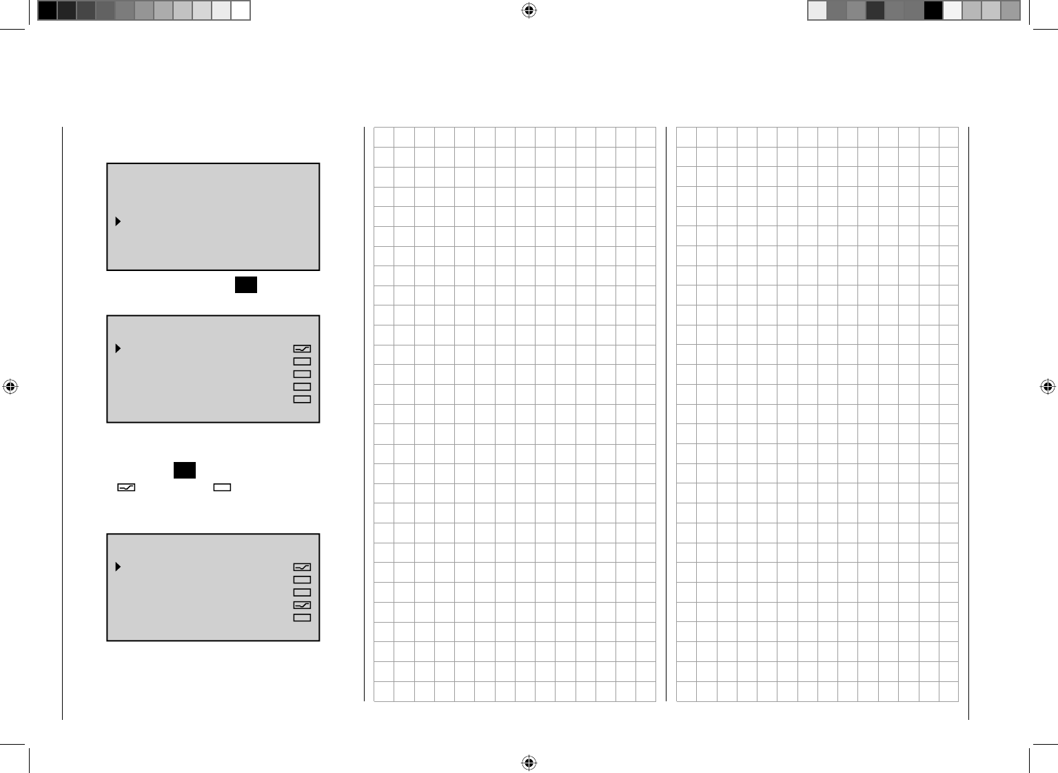
220 Detail program description - Control adjust
SENSOR SELECT
After selection of the desired menu line with the arrow
keys cd of the left or right touch pad…
TELEMETRY
SETTING & DATA VIEW
SENSOR SELECT
RF STATUS VIEW
VOICE TRIGGER
TEL.RCV rcv ch1
… and then pressing the central SET key of the right
touch pad, the selected submenu opens:
SENSOR SELECT
RECEIVER
GENERAL MODULE
VARIO MODUL
ELECTRIC AIR.MOD
GPS
Here, after selection of the desired line with the arrow
keys cd of the left of right touch pad and then
pressing the central SET key of the right touch pad,
activate ( ) or deactivate ( )the data output of the
sensor connected to a receiver with active telemetry
connection. It is only possible to select one sensor, e. g.:
SENSOR SELECT
RECEIVER
GENERAL MODULE
VARIO MODUL
ELECTRIC AIR.MOD
GPS
This selection is required to show the sensor in the "VOICE
TRIGGER" submenu and for the display of the telemetry
data in the corresponding graphic displays, page 32.
221
Detail program description - Control adjust
After selection of the desired menu line with the arrow
keys cd of the left or right touch pad …
TELEMETRY
SETTING & DATA VIEW
SENSOR SELECT
RF STATUS VIEW
VOICE TRIGGER
TEL.RCV rcv ch1
… and then pressing the central SET key of the right
touch pad, the selected submenu opens. This provides
a visualization of the quality of the connection of
transmitter and receiver:
R100%
SD 40
E 10
RD 51
4.8VC
S 90%
4.8VM 0123456789ABCDE
Top row: Reception power of the channels 1 ...
75 of the 2.4 GHz band in dBm coming
from the receiver to the transmitter.
Bottom row: Reception power of the channels 1 ...
75 of the 2.4 GHz band in dBm coming
from the transmitter to the receiver.
Comments:
Since the reception power is measured and •
represented in dBm, the reception power is
increasingly worse the higher the bar is and vice
versa; for this purpose, see also "Reception power
(S-dBm)" on page 224.
Mark the points above the columns with the poorest •
RF STATUS VIEW
reception power since switching on the transmitter
or the resetting of the display by simultaneously
pressing the keys cd or ef of the right touch pad
(CLEAR).
Additional fi gures are shown to the left of the graphic
representation of the reception power. These mean:
Value Explanation
E Signal quality in % of the signal
received from the receiver
S Signal quality in % of the signal
received by the receiver
SL Reception power in dBm
P Number of lost data packages of the
receiver
RL Reception power in dBM of the signal
received by the receiver
RS Current operating voltage of the
receiver in volts
RM Lowest receiver operating voltage
since last startup, in volts
222 Detail program description - Control adjust
After selection of the desired menu line with the arrow
keys cd of the left or right touch pad …
TELEMETRY
SETTING & DATA VIEW
SENSOR SELECT
RF STATUS VIEW
VOICE TRIGGER
TEL.RCV rcv ch1
… and then pressing the central SET key of the right
touch pad, the selected submenu opens:
REPEAT
VOICE TRIGGER
REPEAT 1SEC
TRIG
TRANSFER
RECEIVER
–––
–––
VARIO –––
In order to be able to start the voice output through the
headphone connection, at the very least the "REPEAT"
line must be assigned to a switch. The takes place as
described in the section "Switch and control switch
assignments" on page 52:
VOICE TRIGGER
REPEAT 1SEC
TRIG
TRANSFER
RECEIVER
–––
–––
VARIO –––
Move desired switch
to ON position
VOICE TRIGGER
–––
3
–––
VOICE TRIGGER
REPEAT 5SEC
TRIG
TRANSFER
RECEIVER
VARIO
With this switch you can have the last respective voice
trigger repeated for the duration of the time set to the left
of the switch, as long as the assigned switch is closed:
TRIG
With a switch assigned to this line, preferably one of
the two pushbuttons SW 1 or SW 9, switch to the next
voice output in the rotation selected in the options
"TRANSMITTER", "RECEIVER" and "SENSOR" as
described in the following.
1
3
–––
VOICE TRIGGER
REPEAT 5SEC
TRIG
TRANSFER
RECEIVER
VARIO
VARIO
If you activate the "VARIO MODULE" line( ) in the
"SENSOR SELECT" submenu, described on page 220,
you can use the headphone connection to activate a
switch assigned to this line completely independently
of the other voice triggers, in other words voice triggers
triggered by changes in altitude, such as "Slow climb/
descent", etc.
1
3
8
SENSOR
VOICE TRIGGER
REPEAT 5SEC
TRIG
TRANSFER
RECEIVER
VARIO
TRANSMITTER
After selection of the desired menu line with the arrow
keys cd of the left or right touch pad...
1
3
8
SENSOR
VOICE TRIGGER
REPEAT 5SEC
TRIG
TRANSFER
RECEIVER
VARIO
… and then pressing the central SET key of the right
touch pad, the selected submenu opens:
TX VOLT:
MODEL TIME:
BATTERIETIME:
TIMER(GE:)CENTER:
TIMER(GE.)TOP:
TIME:
Here, after selection of the desired line with the arrow
keys cd of the left or right touch pad and then
pressing the central SET key of the right touch pad,
activate ( ) or deactivate ( ) the data output of the
selected voice trigger:
223
Detail program description - Control adjust
TX VOLT:
MODEL TIME:
BATTERIETIME:
TIMER(GE:)CENTER:
TIMER(GE.)TOP:
TIME:
RECEIVER
After selection of the desired menu line with the arrow
keys cd of the left or right touch pad …
1
3
8
SENSOR
VOICE TRIGGER
REPEAT 5SEC
TRIG
TRANSFER
RECEIVER
VARIO
… and then pressing the central SET key of the right
touch pad, the selected submenu opens:
TEMP:
STRENGHT:
RX VOLT:
LOWVOLT:
Here, after selection of the desired line with the arrow
keys cd of the left or right touch pad and then
pressing the central SET key of the right touch pad,
activate ( ) or deactivate ( ) the selected voice
trigger.
SENSOR
This line only appears if a sensor was fi rst activated in
the "SENSOR SELECT" submenu:
1
3
SENSOR
8
VOICE TRIGGER
REPEAT 5SEC
TRIG
TRANSFER
RECEIVER
VARIO
If, for example, the "VARIO" sensor was selected, after
selection of the "SENSOR" line and then pressing the
central SET key of the right touch pad, the following
display appears:
ALTITUDE:
MAXALT:
MINALT:
VOLT MINIMUM:
As described in the left column, you can also activate
() or deactivate ( ) the voice trigger of the desired
line after pressing the central SET key of the right touch
pad.
Notice:
The selection made here is completely independent of
the "VARIO" voice triggers.
224 Detail program description - Control adjust
Using the arrow keys of the left or right touch pad, scroll
to the "Basic Settings" menu item of the multifunction
menu:
Telemetry
info display
Basic settings
Servo display
Servo test
Code lock
By briefl y pressing the central SET key of the right touch
pad, this menu item opens:
Batterie type
Batterie warning
Touch Sense
Contrast
Ni-MH
Display light
Region
Voice volume
2
4.7V
0
Euro
3
unlim.
Beep volume 3
BASIC SETTINGS
Own
Stick mode 1
DSC Output PPM10
Pitch min back
Power-on beep yes
Power on warn. unlim
General basic settings are entered in this menu …
specifi c to the transmitter, such as the owner's name
and defaults for new model memories.
The settings saved in this menu in the lines ...
"Stick mode",•
"DSC Output",•
"Pitch min"•
… have no infl uence whatsoever on already existing
model memories; they are only defaults, which are
automatically adopted to newly initialized model
memories and can be changed there on an individually
basis at any time in the "Basic model settings"
and "Helicopter type" menus. A change to the
"specifi cations" in this menu, therefore, only infl uences
model memories created at a later time.
Notice:
Settings in this menu are only assigned once for
transmitters. After opening this menu in another model
memory, therefore, the last valid settings always appear.
Select the appropriate line with the arrow keys cd of
the left or right touch pad and then press the central
SET key of the right touch pad. In the inverse value fi eld
you can now change the respective specifi ed value with
the arrow keys of the right touch pad and complete your
entry by pressing the central SET key of the right touch
pad or the ESC key of the left touch pad.
Own(er)
H.J.Sandbrunner
1
PPM10
BASIC SETTINGS
Own
Stick mode
DSC Output
Pitch min back
Up to 15 characters can be used to specify the owner's
name. Change to the next screen page ( ) by
pressing the SET key of the right touch pad:
!"#$%&’()+,–./012
3456789:;
Owner H-J Sandb
FGHIJKLMNOPQRSTUVWX
YZ[¥]^_`abcdefghijk
?@ABCDE
Select the desired characters with the arrow keys of
the left touch pad. Switch to the next position by briefl y
pressing the arrow key f of the right touch pad of the
SET key to be able to select the next character. A blank
space can be entered by simultaneously pressing the
keys cd or ef of the right touch pad (CLEAR).
You can reach any arbitrary character position within the
input fi eld with the ef keys of the right touch pad.
You return to the previous menu page by briefl y pressing
the central ESC key of the left touch pad.
S t i c k mode (specifi cation)
As a basic principle, there are four different ways to
assign the four control functions, aileron, elevator,
rudder and throttle or brake fl aps for winged models as
well as rolling, pitching, tail rotor and throttle/pitch for
helicopter models to the two joysticks. The model pilot
determines which way to do so according to individual
preferences.
With the arrow keys cd of the left or right touch pad,
select the "Stick mode" line. The selection fi eld is shown
in a box:
General settings
Basic transmitter settings
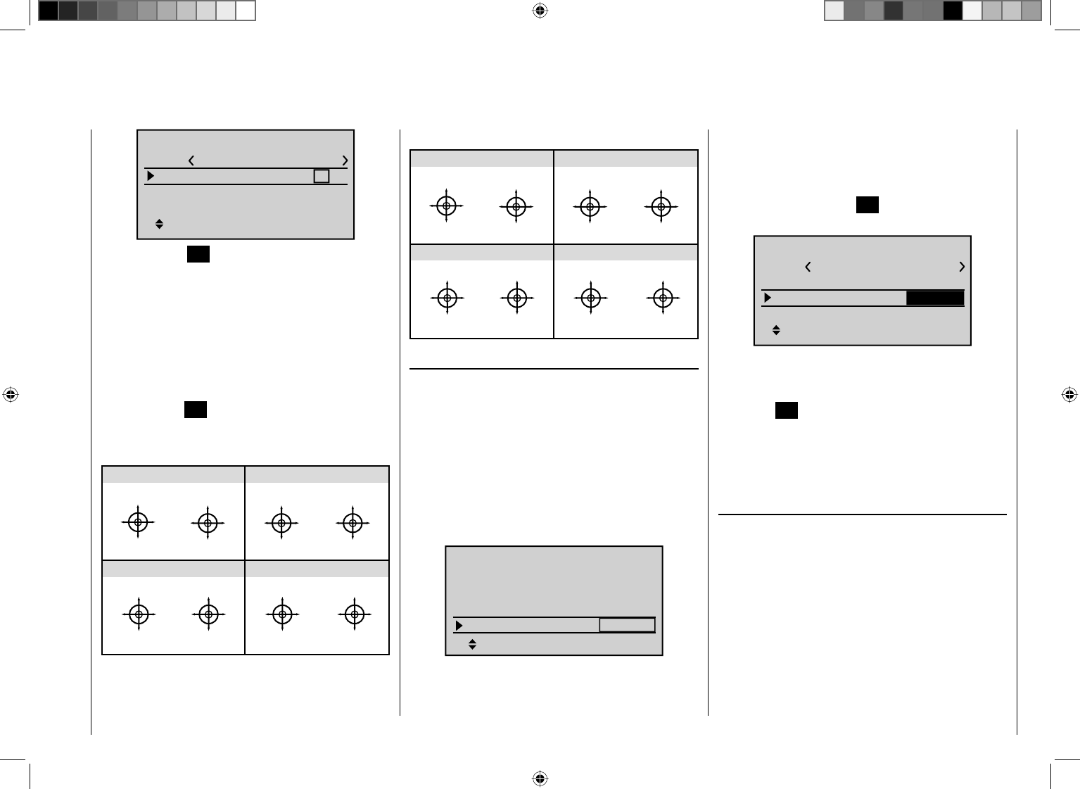
225
Detail program description - Control adjust
H-J Sandbrunner
1
PPM10
SEL
BASIC SETTINGS
Own
Stick mode
DSC Output
Pitch min back
Briefl y press the SET key. The current stick mode is
shown inversely. Now, using the arrow keys of the
right touch pad, select the alternative you use most
frequently, from 1 to 4. In the future this will be used for
newly initialized model memories, but can be changed
on an individual basis for up to 24 model memories.
After simultaneously pressing the keys cd or ef of
the right touch pad (CLEAR), the display returns to stick
mode "1"
By pressing the SET key again, you deactivate the
selection fi
eld in order to switch lines.
Winged model stick mode
“MODE 2” (Throttle at left stick)
“MODE 3” (Throttle at right stick) “MODE 4” (Throttle at left stick)
“MODE 1” (Throttle at right stick)
elev. down
elev. up
left rudder
right rudder
full throttle
idle
left aileron
right aileron
full throttle
left rudder
right rudder
idle
elev. down
elev. up
left aileron
right aileron
elev. down
elev. up
left aileron
right aileron
Motor Vollgas
idle
left rudder
right rudder
full throttle
idle
left aileron
right aileron
elev. down
elev. up
left rudder
right rudder
Helicopter model stick mode
“MODE 2” (Throttle at left stick)
“MODE 3” (Throttle at right stick) “MODE 4” (Throttle at left stick)
“MODE 1” (Throttle at right stick)
pitch axis
tail rotor
pitch axis
tail rotor
throttle
roll
roll
throttle
tail rotor
tail rotor
throttle throttle
pitch axis
pitch axis
roll
roll
pitch axis
pitch axis
roll
roll
Motor/Pitch
throttle
tail rotor
tail rotor
throttle
throttle
roll
roll
pitch axis
pitch axis
tail rotor
tail rotor
DSC Output (specifi cation)
In the line with the same name in the "Base setup
model" menu you can determine which of the three
available modulation types should be provided for the
DSC socket separately for each model memory. This
selection primarily infl uences the number of maximum
control channels available at the DSC socket and
thus for a fl ight simulator or LS system connected at
this socket. With the selection of "PPM10", this is the
channels 1 ... 5, with "PPM18" the channels 1 ... 9 and
with "PPM24" the control channels 1 ... 12.
SEL
99sec
DSC output PPM10
RF Range Test
R12 R08
OFF
BASIC SETTINGS, MODEL
Rcv Ch Map
RF transmit
In this "General settings" menu, you can determine
which of the three possible "Modulation types" should
be adopted as the default to a newly initialized model
memory in the line "DSC Output" the same way as with
"Stick mode".
If necessary, using the arrow keys cd of the left or
right touch pad, switch to the "DSC Output" line and, by
briefl y pressing the central SET key of the right touch
pad, activate the value window:
H-J Sandbrunner
1
SEL
BASIC SETTINGS
Own
Stick mode
DSC Output
Pitch min back
PPM10
Now you case choose between the three possible
modulation types "PPM10", "PPM18" and "PPM24"
using the arrow keys of the right touch pad. By pressing
the central SET key of the right touch pad again, you
complete the entry.
Simultaneously pressing the keys cd or ef of the
right touch pad (CLEAR) returns to "PPM10".
(Default) Pitch min
(only relevant for helicopter models)
Enter your preferred actuation direction for the throttle/
pitch joystick analogously to the "Stick mode" and "DSC
Output" options described above, in order to be able
to fi nd it for newly initialized model memories in the
future. The functions of all other options of the helicopter
program depend on this setting, insofar as they pertain to
the throttle and pitch function, in other words the throttle
curve, idle trim, Channel 1 ¼ tail rotor mixer, etc.
The following meanings apply:
"front": minimum front pitch setting, the pitch joystick
(C1) points away from the pilot.
226 Detail program description - Control adjust
"rear": minimum rear pitch setting, the pitch joystick
(C1) points towards the pilot.
Simultaneously pressing the keys cd or ef of the
right touch pad (CLEAR) switches to "rear"
Notice:
The stick mode of the C1 joystick in the winged model
program for "Throttle min front/rear" can be individual
changed in the "Model type" menu.
Contrast
In order to guarantee the optimal visibility of the display
of the mc-32 HoTT in any weather and at any
temperature, you can adjust its contrast:
GRAUBELE
#01
2:22h
Stop
Flt
«normal »
K78
0:00
0:00
5.5V
5.2V
M
HoTT
GRAUBELE
#01
2:22h
Stop
Flt
«normal »
K78
0:00
0:00
5.5V
5.2V
M
HoTT
For this purpose, using the arrow keys cdof the left or
right touch pad, select the "Contrast" line:
1
SEL
PPM10
0
Contrast
BASIC SETTINGS
Stick mode
DSC Output
Pitch min back
Then briefl y press the central SET key of the right touch
pad. Now you can adjust the display contract in a range
of ±20 using the arrow keys of the right touch pad in the
inverse value fi eld.
Simultaneously pressing the arrow keys cd or ef
of the right touch pad (CLEAR) resets the inverse fi eld
to "0".
Display light
In this line you can determine how long the backlight of
the display should remain switched on after switching on
the transmitter or the last key actuation.
The available options are "unlim(ited), "30 s", "60 s" and
"120 s".
Simultaneously pressing the arrow keys cd or ef
of the right touch pad (CLEAR) sets the inverse fi eld to
"unlimited".
Power-on beep
In this line you can switch the power-on beep of the
transmitter on ("yes") and off ("no").
Simultaneously pressing the arrow keys cd or ef
of the right touch pad (CLEAR) switch the inverse fi eld
back to "yes".
Battery type
SEL
0
Ni-MH
Battery type
Contrast
Display light unlim.
BASIC SETTINGS
Power-on beep yes
In this line you indicate to the transmitter whether its
power supply is provided from a four-cell NiMH battery
or a single-cell LiPo battery. Depending on this setting,
you are offered a suitable voltage range in the (next) line
"Battery warning".
Simultaneously pressing the arrow keys cd or ef of
the right touch pad (CLEAR) switches back to "Ni-MH"
in the inverse fi eld.
Battery warning threshold
SEL
Ni-MH
4.7V
Battery type
Battery warning
Display light unlim.
BASIC SETTINGS
Power-on beep yes
You can arbitrarily specify the warning threshold for the
display ...
battery
needs
charging
… – depending on the selection of the battery type in
the line above it – in increments of 0.1 volt between 4.5
and 5.5 V (NimH battery) or 3.4 and 4.2 V (LiPo battery.
227
Detail program description - Control adjust
Make sure that you do not enter a value which is too
low, so that you still have suffi cient time to safely land
your model in the event of a battery warning.
Simultaneously pressing the arrow keys cd or ef
of the right touch pad (CLEAR) switches back to the
factory default values 4.7 or 3.4 V in the inverse fi eld.
Power-on warning
SEL
Ni-MH
4.7V
Batterie type
Batterie warning
BASIC SETTINGS
Power-on beep yes
Power on warn. unlim
In this line you can determine how long the transmitter
should wait after the last actuation of an operating
element until the activation of an optical and acoustic
power-on warning before the transmitter switches off
automatically one minute later.
The values "unlim(ited)", "30 s" and 1, 5, 10, 20, 30 and
60 minutes are optional selections.
Simultaneously pressing the arrow keys cd or ef of
the right touch pad (CLEAR) switches to "unlimited" in
the inverse fi eld.
Notice:
In order to be able to restart the transmitter after
automatic shut-off, slide the power switch of the
transmitter fi rst towards the display, to the "OFF" position
and, after approx. fi ve seconds, back towards the
antenna to the "ON" position.
Touch sensitivity
SEL
Ni-MH
4.7V
2
Batterie type
Batterie warning
Touch Sense
BASIC SETTINGS
Power on warn. unlim
In this line you can select the touch sensitivity of the
touch pads in a range from 1 to 10.
Simultaneously pressing the arrow keys cd or ef of
the right touch pad (CLEAR) resets to "2" in the inverse
fi eld.
Region
SEL
4.7V
2
Euro
Batterie warning
Touch Sense
Region
BASIC SETTINGS
Power on warn. unlim
The region is needed for compliance with various
regulations (FCC, ETSI, IC etc.). In France, for example,
the operation of a remote control is only permitted within
a limited frequency band. Therefore, the region setting of
the transmitter MUST be switched to "France" mode
as soon as it is operated in France. In no case may
the Universal/EURO mode be used in France!
Simultaneously pressing the arrow keys cd or ef
of the right touch pad (CLEAR) resets to "Euro" in the
inverse fi eld.
Voice volume
SEL
2
Euro
3
Touch Sense
Region
Voice volume
BASIC SETTINGS
Power on warn. unlim
The volume of the voice output through the earpiece
connection is defi ned in a range of "0" to "10" in this line.
Simultaneously pressing the arrow keys cd or ef of
the right touch pad (CLEAR) resets to "3" in the inverse
fi
eld.
Beep volume
SEL
2
Euro
3
3
Touch Sense
Region
Voice volume
Beep volume
BASIC SETTINGS
The volume of the transmitter's internal beep generator
is defi ned in a range from "0" to "6" in this line.
Simultaneously pressing the arrow keys cd or ef of
the right touch pad (CLEAR) resets to "3" in the inverse
fi
eld.

228 Detail program description - Control adjust

229
Detail program description - Control adjust
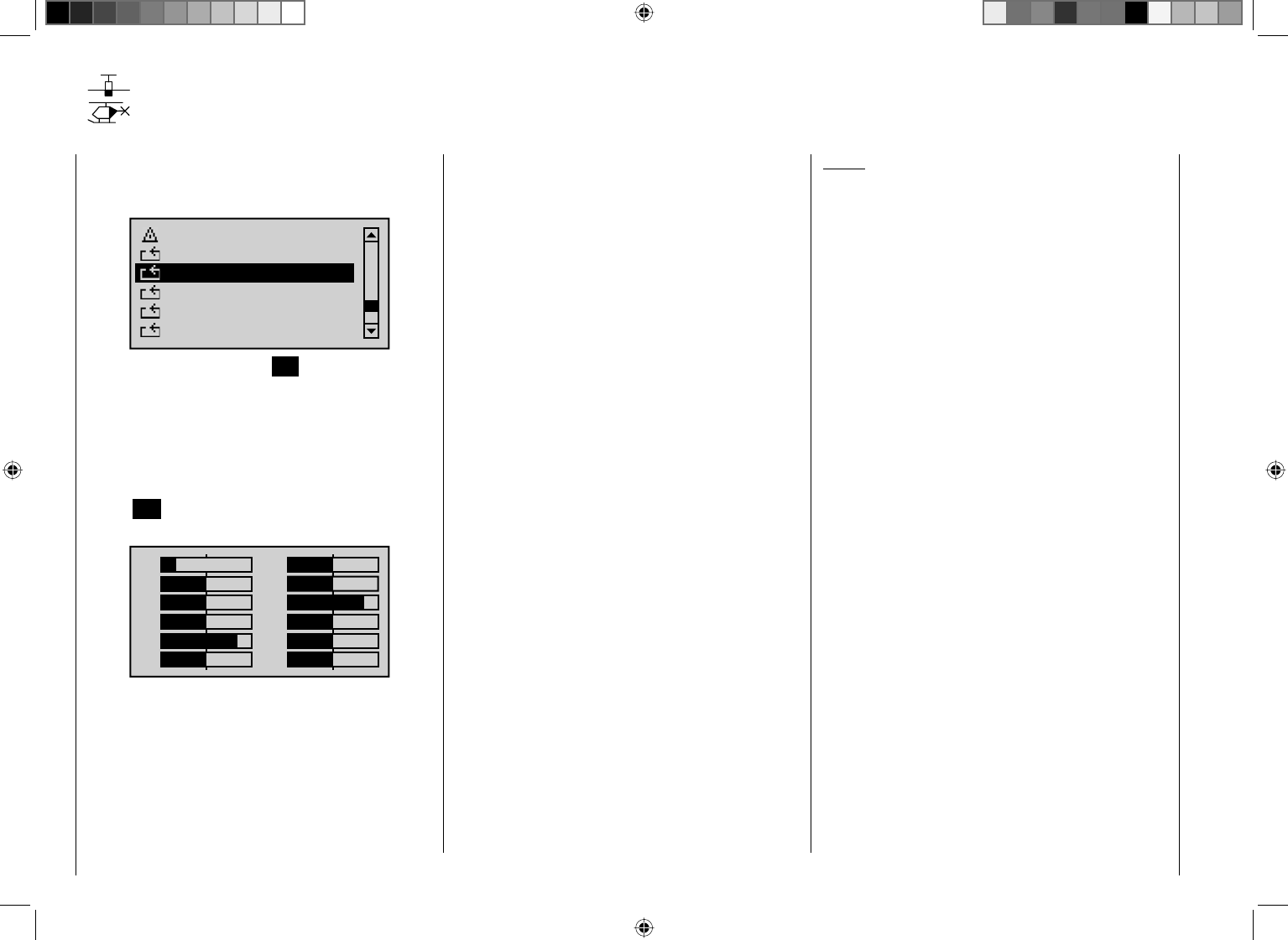
230 Detail program description - Control adjust
Servo display
Display of the servo position
Scroll to the menu item "Servo display" of the
multifunction menu using the arrow keys of the left or
right touch pad:
Telemetry
info display
Basic settings
Servo display
Servo test
Code lock
By briefl y pressing the central SET key of the right touch
pad, you open this menu item.
The visual display of the current servo positions,
however, can be opened both by selecting this menu
and by simultaneously pressing the keys ef left touch
pad directly from the base screen of the transmitter, as
well as nearly all menu positions. By briefl y pressing the
central ESC key of the left touch pad, you return to the
respective starting point.
1
3
5
7
+
0%
0%
9
11
0%
0%
2
4
6
8
+
0%
0%
0%
0%10
12 0%
–100%
+100%
+100%
The current position of a servo is displayed in a bar
diagram between -150 % and +150 % of the normal
path, in consideration of the control and servo settings,
the dual-rate/expo functions, the interplay of all active
linear and curve mixers, etc. 0 % corresponds precisely
to the servo center position. This way, you can quickly
check your settings without having to switch on the
receiver. However, this does not absolve you from fi rst
carefully testing all program steps, as well as on the
model, prior to the fi rst operation of the model in order to
eliminate errors!
For winged models the display takes place
according to the following scheme:
Bar 1 = Throttle/brake servo
Bar 2 = Aileron or left aileron
Bar 3 = Elevator
Bar 4 = Rudder
Bar 5 = Right aileron
Bar 6 = Camber-changing fl ap (left) / free channel
Bar 7 = Right camber-changing fl ap / free channel
Bar 8 = Free channel / second elevator servo
Bar 9 = Free channel / Left FL2
Bar 10 = Free channel / Right FL2
Bar 11 = Free channel
Bar 12 = Free channel
… and with helicopter models:
Bar 1 = Pitch or roll (2) or pitch (2) servo
Bar 2 = Roll (1) servo
Bar 3 = Pitch (1) servo
Bar 4 = Tail servo (gyro)
Bar 5 = Pitch (2) servo / free channel
Bar 6 = Throttle servo or speed controller
Bar 7 = Gyro sensitivity / free channel
Bar 8 = Speed regulator / free channel
Bar 9 = Free channel
Bar 10 = Free channel
Bar 11 = Free channel
Bar 12 = Free channel
Notice:
However, please note that the servo display is only •
based on the original sequence of servos, so any
switching of the outputs do not take place in either
the "Transmitter output" menu or "Receiver output"
menu.
The number of channels shown in this menu •
correspond to the 12 control channels available in the
mc-32 HoTT transmitter. The number of actually
usable channels, however, depends on the receiver
type as well as the number of servos connected to
it and, therefore, may be considerably lower under
certain circumstances.
Use this display during the model programming, •
because you can immediately check all settings on
the transmitter. However, this does not absolve you
from fi rst carefully testing all program steps, as well
as on the model, prior to the fi rst operation of the
model in order to eliminate errors!
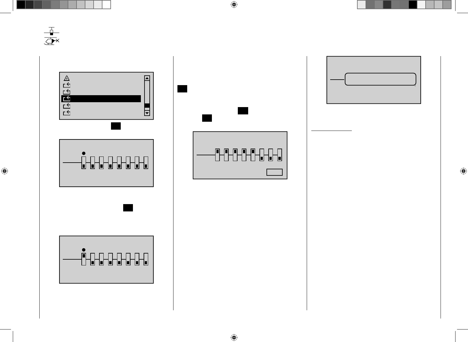
231
Detail program description - Control adjust
Servo test
Function test of Servo 1 … 8
Scroll with the arrow keys of the left or right touch pad to
the menu item "Servo test" of the multifunction menu:
Telemetry
info display
Basic settings
Servo display
Code lock
Servo test
By briefl y pressing the central SET key of the right touch
pad, this menu item opens:
SERVO TEST
act
off
12345678
0.5s
Any of the inputs 1 ... 8 can be activated for the servo
test by selecting with the arrow keys of the left or right
touch pad and then briefl y pressing SET key of the right
touch pad. As soon as you have set only one of the
inputs 1 ... 8 to "active", the following notice appears at
the bottom of the display screen:
12345678
0.5sCLR=act./deact.
SERVO TEST
act
off
Simultaneously pressing the arrow keys cd or ef of
the right touch pad (CLEAR) would now start and stop
the servo test for input "1", fo r example, with a cycle
time of 0.5 s.
To change the cycle time, select the time input fi eld
with the arrow keys of the left or right touch pad. After
activation of the input fi eld by briefl y pressing the central
SET key of the right touch pad, the movement cycle
can be changed in 0.5 s increments between 0.5 s and
3.0 s using the arrow keys of the left or right touch pad.
Briefl y pressing the central ESC of the left touch pad or
the central SET key of the right touch pad completes the
time presetting.
12345678
3.0sHLD = aktiviert
SERVO TEST
act
off
The "servo test" function started by simultaneously
pressing the arrow keys cd or ef of the right touch
pad (CLEAR) automatically control all servos as though
the would simultaneously and permanently move the
corresponding control back and forth between -100
% and +100 % in the set time. All active mixing and
coupling functions in the respective model memory,
therefore, are effective and the servos move within the
specifi ed servo paths and servo delimitations.
As soon as you have started the servo test by
simultaneously pressing the arrow keys cd or ef of
the right touch pad (CLEAR), a window opens:
12345678
3.0sCLR=act./deact.
Servo test act.
SERVO TEST
act
off
Simultaneously press the arrow keys cd or ef of
the right touch pad (CLEAR) in order to end the test.
Important notice:
The shut-off of the transmitter does not
automatically end an active servo test. Therefore,
always stop a servo test manually BEFORE
SHUTTING OFF the transmitter, because the servo
test is otherwise restarted after switching on the
transmitter again.
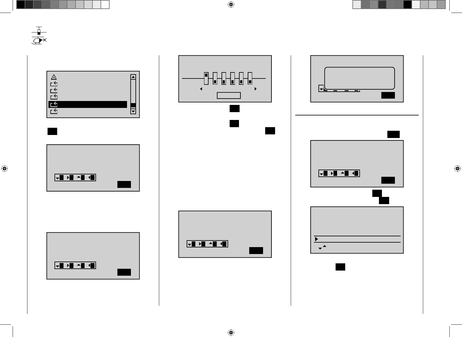
232 Detail program description - Control adjust
Code lock
Locking of the multifunction list
Scroll with the arrow keys of the left or right touch pad to
the menu item ...
Telemetry
info display
Basic settings
Servo display
Servo test
Code lock
… of the multifunction menu. By briefl y pressing the
central SET key of the right touch pad, this menu item
opens:
CODE LOCK
Desired (new)
secret number
(_ )
SET
321 3 4
Access to the multifunction menu can be locked for
unauthorized use by a four-digit secret code comprised
of the numbers 1 to 4, which you enter according to the
scheme shown in the display with the arrow keys of the
left touch pad; for example :
(123_)
CLR
321 3 4
CODE LOCK
Desired (new)
secret number
As soon as you not enter the fourth number by pressing
one of the other arrow keys of the left touch pad, the
following notice appears in the display:
789
10 11 12
STO
FAIL SAFE
Pos
hold
DELAY : 0.25s
By briefl y pressing the central ESC key of the left touch
pad, you confi rm the secret code and leave the menu.
By briefl y pressing the central SET key of the right touch
pad, on the other hand, you confi rm the active CLR fi eld
in the bottom right in the display and thereby delete the
number you entered.
Make note of the secret code and keep it safe.
Otherwise, the transmitter must be sent in to
Graupner Service for decoding.
The lock becomes active the next time the transmitter
is switched on. However, the control remains ready
for operation. Calling the multifunction list and thereby
a model change, for example, is no longer possible
without entering the correct number combination:
(_ )
SET
321 3 4
CODE LOCK
Desired (new)
secret number
A renewed attempt following an incorrect entry is only
possible after the lapse of a time-out.
(123_)
CLR
321 3 4
CODE LOCK
Desired (new)
secret number
Input error
Time lock
Deletion of the secret code
If the secret code should be deleted again at a later
point in time, after opening this menu, immediately press
the central SET key of the right touch pad twice :
(1234)
CLR
321 3 4
CODE LOCK
Desired (new)
secret number
The fi rst time you press the central SET key of the right
touch pad, the secret code is deleted (CLR):
1.234
2048MB
2011/02/01(Mo )
11:22:33s
1234MB
firmware ver.
date
time
SD-Card
available
And the second time you press the key the empty input
fi eld is confi rmed (SET). The display shows:
233
Detail program description - Control adjust
(123_)
SET
321 3 4
CODE LOCK
Desired (new)
secret number
Memorise secret
¾¾¾¾¾ ¾¾¾¾¾
none
Now leave the menu by briefl y pressing the central ESC
key of the left touch pad.
Leaving the menu without input of a secret code
You would like to leave the menu opened out of curiosity
or by accident and have not pressed any other key.
Therefore, the display appears as follows:
1.234
2048MB
2011/02/01(Mo )
11:22:33s
1234MB
firmware ver.
date
time
SD-Card
available
Press the central SET key of the right touch pad once.
The following display appears:
(123_)
SET
321 3 4
CODE LOCK
Desired (new)
secret number
Memorise secret
¾¾¾¾¾ ¾¾¾¾¾
none
Now leave the menu by briefl y pressing the ESC key of
the left touch pad.
Tip:
If you generally want to dispense with a programmer
lock, you should, if applicable, remove this menu from
the multifunction list with "Suppress menus" so that
unauthorized persons cannot enter a secret code "on
the sly".
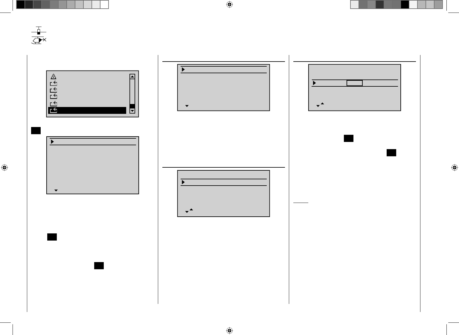
234 Detail program description - Control adjust
Info display
Transmitter ID, date, time and memory card
With the arrow keys of the left or right touch pad, scroll
to the menu item ...
Telemetry
Basic settings
Servo display
Servo test
Code lock
info display
… of the multifunction menu. Briefl y pressing the central
SET key of the right touch pad opens this menu:
RFID
firmware ver.
date
time
SD-Card
available
1.234
0MB
0%
ABCDEF12
2011/08/01(Mo )
11:22:33s
0MB
Transmitter-specifi c information is shown in this menu
and – insofar as necessary and benefi cial – also
changed.
Select the appropriate line with the arrow keys cd
of the left or right touch pad and then briefl
y press the
central SET key of the right touch pad. In the inverse
value fi eld you can now change the respective default
value – insofar as possible and necessary – with the
arrow keys of the right touch pad and complete your
entry by pressing the central SET key again.
RFID
1.234
0MB
ABCDEF12
2011/08/01(Mo )
11:22:33s
RFID
firmware ver.
date
time
SD-Card
The RF identifi cation number of the transmitter is shown
in this line. It is transmitter-specifi c, is only issued once
per transmitter and cannot be changed. During the
connection process, this is sent to the receiver, among
other things, so that it is always capable of identifying
the radio signals of "its" transmitter.
Firmware Version
1.234
0MB
ABCDEF12
2011/08/01(Mo )
11:22:33s
RFID
firmware ver.
date
time
SD-Card
The current version number of the transmitter software
is shown in this line.
Through a comparison of the number shown here with
the update version offered on the internet download
page of the corresponding product under www.graupner.
de, you can determine whether a current update of the
transmitter operating system is available.
If applicable, the version number is also required for
inquiries with the service department.
D a t e
1.234
0MB
ABCDEF12
2011/08/01(Mo )
11:22:33s
RFID
firmware ver.
date
time
SD-Card
If necessary, select this line with the arrow keys of the
left or right touch pad and, if applicable, the month or
date fi eld. After activation of the respective value fi eld
by pressing the central SET key of the right touch pad,
the year, month or date can be set with the arrow keys
of the right touch pad. Pressing the central SET key of
the right touch pad again completes the respective entry.
Years ranging from 2000 to 2135 are available.
The abbreviated day of the week to the right outside in
brackets is automatically generated from the respective
date.
Notice:
If the transmitter is connected to a PC as described •
on page 39, the date and time can also be set
through the PC program provided for the respective
product on the internet page at www.graupner.de.
The date and time are protected against data loss •
due to power failure by a buffer battery for situations
like a battery change, see page 15.
235
Detail program description - Control adjust
Time
1.234
0MB
ABCDEF12
2011/08/01(Mo )
11:22:33s
RFID
firmware ver.
date
time
SD-Card
If necessary, select this line with the arrow keys of the
left or right touch pad and the minute fi eld, if applicable.
After activation of the respective value fi eld by pressing
the central SET key of the right touch pad, the hour or
minute can be adjusted with the arrow keys of the right
touch pad. Pressing the central SET key of the right
touch pad again completes the respective entry.
Contrary to this, the seconds display cannot be directly
adjusted; it can only be restarted by briefl y pressing the
central SET key of the right touch pad with "00".
Notice:
If the transmitter is connected to a PC as described •
on page 39, the date and time can also be set
through the PC program provided for the respective
product on the internet page at www.graupner.de.
The date and time are protected against data loss •
due to power failure by a buffer battery for situations
like a battery change, see page 15.
SD card
1.234
2048MB
ABCDEF12
2011/08/01(Mo )
11:22:33s
RFID
firmware ver.
date
time
SD-Card
In this line the memory capacity of a memory card
inserted in the transmitter, if applicable, is shown in MB.
Depending on the memory capacity of the inserted
micro SD or micro SDHC memory card, it may take
several minutes until the correct value is shown after
switching on the transmitter.
available
1.234
2048MB
2011/02/01(Mo )
11:22:33s
1234MB
firmware ver.
date
time
SD-Card
available
Display of the available storage space in MB.
As mentioned before, the display of the available
storage space – depending on the capacity of the
inserted memory card – does not appear until some time
has passed after switching on the display.
The display of the available storage space in relation to
the total memory capacity is shown in the line below:
2048MB
2011/08/01(Mo )
11:22:33s
1234MB
60%
date
time
SD-Card
available
As mentioned before, the display of the available storage
space – depending on the capacity of the inserted
memory card –does not appear until some time has
passed after switching on the display.
236 Detail program description - Control adjust
mc-32 HoTT programming
Preparatory measures based on the example of a winged model
Programming models in an mc-32 HoTT …
… is easier than it may appear at fi rst!
The basic requirement for "clean" programming,
however, and this applies not only to the mc-32
HoTT, but basically to all programmable transmitters,
is the mechanically correct installation of all remote
control components in the model! Therefore, it should
be ensured no later than on connection of the linkages
that the servos are in their respective neutral position
and their rudder lever is also in the desired position.
Otherwise you should loosen the rudder and re-fasten
it with an offset of a few lobes. If, in the process, the
servos are moved into position using a servo tester,
such as the RC-Tester with Order No. 2894.12, the
"correct" position can be determined very easily.
The possibility of changing the neutral position of a
servo in practically every modern transmitter is only
intended for the fi ne-tuning. Greater deviations from
"0" can result to further asymmetries in the course of
the further signal processing in the transmitter. In the
same manner: A car with a bent chassis does not get
any straighter if only the steering wheel is trimmed to
"straight"!
An additional important point is the adjustment of
the rudder paths: This should take place through
a corresponding adjustment of the steering points,
insofar as possible. Ultimately this is far more effi cient
than extensive efforts with the path adjustments in the
transmitter! In this case: Path adjustments serve fi rst
and foremost for to compensate for the manufacturer-
stipulated tolerances for the servos and their fi ne-tuning,
and less for the compensation of carelessness.
If two separate aileron servos are used for a
winged model, the ailerons, controlled through the
corresponding activated wing mixer – see the following
pages – can be assigned with both the fl ap function and
raised with the brake fl aps – however this would make
more sense in a glider or electro glider than in a motor
model.
In this case the rudder arms – starting from the neutral
position – should be tilted forward one lobe, pointing
toward the nose, set to the respective servo.
The mechanical differentiation achieved through this
asymmetric assembly contributes to the fact that the
brake effect of the elevated ailerons increases with their
defl ection and, therefore, does not normally require a
greater path upward than downward.
Correspondingly, when planning to operated separately
controlled fl ap servos, they should also be integrated
into a crow system. Since the brake effect of this fl ap
position referred to as a "crow position" is infl uenced
less by the elevated ailerons than the downward
defl ection of the fl aps, the rudder arms should be
installed somewhat toward the rear in this case, tilted
toward the trailing edge. As a result, there is a greater
available path for the downward defl ection. With such
a combination of lowered fl aps with raised ailerons,
however, the latter should only be elevated moderately,
because they have more of a stabilizing and controlling
function than a braking function in this type of crow
system.
A "tip" for seeing the brake effect in this connection:
Spread the fl aps and look above and below the surface
from the front. The greater the projected surface of the
protruding rudder, the greater the brake effect.
Outboard ailerons
Inboard camber-changing flaps
(Eine ähnlich asymmetrische Montage der Ruderarme
kann z. B. an Spreiz- bzw. Landeklappen auch in einem
Motormodell sinnvoll sein.)
If a model is completed and mechanically attuned in this
respect, you can basically begin with the programming
of the transmitter. The following examples, an attempt is
made to follow the practice of fi rst describing the general
basic settings and then fi ne-tuning or specializing them
in the subsequent steps. After the initial fl ight and over
the course of the further fl ying in of a model, it may be
necessary to occasionally adjust some of the settings. As
a pilot's experience increases, however, so does the desire
for enhancements and expansions of settings. For this
reason, the sequence of options is not always adhered to
or some options are even mentioned multiple times.
Of course, just the opposite can also be the case,
that not everyone of the described steps is relevant
for a certain model, just as some users may miss the
description of a certain step for their model …
237
Detail program description - Control adjust
whatever the case may be, you should consider a logical
assignment of the control mechanisms before you begin
with the model programming.
For models in which the emphasis is on the "motor",
regardless of whether it is powered by an electric
or combustion motor, there should be no problem
in this respect, because the assignment of the two
joystick units essentially lies in the four basic functions
"Power regulation (= throttle)", "Side", "Altitude" and
"Transverse"! However, in the menu …
"Model type" (beginning 82)
Tail type
Motor at C1
Normal
None
Aile/flaps 1AIL
M O D E L T Y P E
Brake Off In 1+100%
SEL
… you should determine whether you would like
the minimum throttle position in the "front" or "rear",
because "none (motor)" is entered by the program in the
creation of a model memory as a basic principle.
The difference between "no" and "idle front/rear" is
not only in the effect of the C1 trimming, which is over
the entire joystick path with "none" and with "idle front/
rear" only effects the idle direction. In the process,
the "effective direction" of the C1 joystick is adapted
accordingly, so that with a change from "front" to "rear"
or vice versa, the rotational direction of the throttle servo
or brake system do not have to be adapted as well.
In addition, with an "idle front/rear" setting, a warning
indication appears in the display for safety reasons and
issues a warning beep, if the throttle joystick is too far in
the full-throttle direction:
GRAUBELE
#01
2:22h
Stop
Flug
K78
0:00
0:00
0.0V
50%
5.2V
M
HoTT
Throttle
too
high!
In any case, you will also have to consider "special
functions".
With electro gliders, on the other hand, it is only
occasionally different. In this regard, one must ask
how the drive and brake system are actuated. Certain
solutions have shown to be practical and others have
shown to be less practical.
For example, it is certainly less practical, if you have to
release a joystick for the approach of a glider model in
order to be able to appropriately control the spoilers or a
crow position using one of the other controls. It may be
more advantageous to either design the function of the
C1 joystick to be switchable (see Example 4, beginning
on page 247) or to leave the control of the brake system
at the joystick and to control the motor through one of
the other controls or even with a switch! Since this type
of model does not normally have a motor, and just a
"start assistance" function to either "lift" the model in
the sky with full force or, in any case, to "tow" it with
"half" force by a wind fi eld, Therefore, the motor can be
switched on and off without having to release one of the
joysticks – even in the approach. The selection is not
diffi cult with the mc-32 HoTT transmitter.
For the control of the motor you use a two-stage switch
SW 3 or 8 or, even better, one of the two three-stage
switches CTRL 9 or 10. In any case, select a switch
which you can reach easily in order to perform this
option without having to release the joystick. In addition,
this procedure should take place on the transmitter side,
which is modifi ed for a holding hand with a manual start
of the model. In other words: If the model is started from
the right hand, the motor switch should be assigned to
one of the switches available on the left side and vice
versa.
The idea is the same for the control of fl aps, regardless
of whether only ailerons or fl aps covering the entire
wingspan (combinations) are raised or lowered.
If everything is now in order, you can begin with the
programming.
238 Detail program description - Control adjust
Initial steps for the programming of a new model
Example: Winged model with two ailerons and – initially – without motor propulsion
In the scope of the initial commissioning of a new
transmitter, in the selection menu …
"General settings" (page 224)
Batterie type
Batterie warning
Touch Sense
Contrast
Ni-MH
Display light
Region
Voice volume
2
4.7V
0
Euro
3
unlim.
Beep volume 3
BASIC SETTINGS
Own
Stick mode 1
DSC Output PPM10
Pitch min back
Power-on beep yes
Power on warn. unlim
H-J Sandbrunner
… some basic information should be entered. This
serves various purposes:
In this menu the name of the owner can be entered
and defaults can be entered for new model memories
in the lines "Stick mode", "DSC Output" and Pitch
min". These are then adopted on the activation of a new
model memory in its basic settings, but can be changed
there at any time.
In the "Contrast" line, as an alternative to the line with
the same name in the "Hidden mode" menu, page 28,
you can adjust the display contrast by changing the
standard default "0" in a range of ±20.
The setting in the "Display light" line determines how
long the display lighting remains illuminated after the
transmitter is switched on or after the last key actuation.
With the selection of "yes/no" in the "Power-on beep"
you can determine whether the "Recognition melody",
which sounds when switching on the transmitter, is
switched on or off.
In the "Battery type" line you indicate to the transmitter
whether its power supply comes from a four-cell NiMH
battery or a single-cell LiPo- battery and in the "Battery
warning " line you can determine the corresponding
switching threshold for the battery warning on an
individual basis. Make sure that you do not enter a
value which is too low, so that you do not have suffi cient
time to safely land your model in the event of a battery
warning.
In the "Power-on warning" line, you can determine, as
necessary, how long the transmitter should wait after the
last actuation of an operating element until the activation
of an optical and acoustic power-on warning, whereas
the settings in the lines "Touch sensitivity", "Voice
volume" and "Signal volume" are provided for personal
comfort.
On the other hand, the setting in the "Region" is
anything but a matter of taste and is determined by
statutory regulations: Therefore, when in France,
only commission the transmitter with the "France"
setting.
You can leave this menu after completion of your
"General settings" with the central ESC key of the left
touch pad to return to the multifunction list.
For the programming of a new model, now use the
arrow keys of the left or right touch pad to switch to the
menu ...
"Select model" (page 63)
…, and with the select a free model memory location
with the arrow keys of the right or left touch pad:
03
04
05
¿¿¿ free¿¿¿
02
01
06
R12
¿¿¿ free¿¿¿
¿¿¿ free¿¿¿
¿¿¿ free¿¿¿
¿¿¿ free ¿¿¿
Immediately after pressing the central SET key of the
right touch pad for the confi rmation of this selection, the
type of model to be programmed is requested:
Select model type
Since we want to work with a winged model in this
section, the symbol for a winged model is confi rmed by
pressing the central SET key of the right touch pad. The
display switches back to the base screen.
Notice:
Of course, you can also use the predefi ned default •
"winged model" supplied with the receiver as model
memory 01 for the programming of your fi rst model.
Once the "Select model type" option has been •
opened, the process can no longer be canceled!
Even if you switch off the transmitter, this selection
must be made! In any case, you can undo this by
subsequently deleting the respective model memory.
239
Detail program description - Control adjust
If the battery voltage is too low, you cannot switch •
models for safety reasons. A corresponding message
appears in the display:
not possible now
voltage too low
Once this fi rst hurdle is cleared, the connection of the
receiver built into the model to this model memory can
be made in the menu …
""Basic model settings" (page 68 … 73)
. For this purpose, switch to the line "RF bind":
1
n/a
n/a
BD1
GRAUBELE
BD2
RF transmit n/v OFF
Mod.name
Stick mode
RF BIND
BASIC SETTINGS, MODEL
Notice:
After confi rmation of the model selection in the base
screen, if you confi rm the message appearing in the
screen for a few seconds …
BIND N/A
OK
… by pressing the SET key of the right touch pad, you
automatically come to this line.
In this line you delete the connection process between
model memory and receiver, as described in detail on
page 69. Otherwise, you cannot address the receiver.
Afterwards, using the arrow keys c of the left or right
four-way pad, move up to the fi rst line and begin with the
actual model programming in the "Mod. Name" line:
1
n/a
BD2
BD1
n/aR12
bind
Mod.name
Stick mode
RF BIND
BASIC SETTINGS, MODEL
Rcv Ch Map
Now enter the "Model name" here by briefl y pressing
the central SET key of the right touch pad to switch to
the character map:
!"#$%&’()+,–./012
3456789:;
Mod Name GRAUB
FGHIJKLMNOPQRSTUVWX
YZ[¥]^_`abcdefghijk
?@ABCDE
If applicable, the defaults adopted from the "General
settings" menu for "Stick mode" and "DSC output"
are also checked and changed as necessary.
In the menu …
"Model type"
Tail type
Motor at C1
Normal
None
Aile/flaps 1AIL
M O D E L T Y P E
Brake Off In 1+100%
SEL
… the principle arrangement of the servos in the model
is selected and communicated to the transmitter. The
following selections are available:
"Motor at C1"
"none"•
Trimming works independently of the joystick position
and the "Brake settings" submenu of the "Wing
mixers" menu, beginning on page 146, is available
without limitation.
The "Throttle too high" warning message, see
page 36 and/or 61, and the "Motor stop" option are
deactivated.
"(Idle) front or rear"•
C1 trimming is affected in the front or rear and the
"Motor stop" option is activated.
If the throttle joystick is too far in the full throttle
direction when switching on the transmitter, this is
indicated to you with the warning message "Throttle
too high".
In parallel to this, the "Brake settings" submenu of
the "Wing mixers" menu, beginning on page146,
is only available if "none" is entered in the "Motor"
column for the currently active fl ight phase in the
"Phase settings" menu, page 128.
In the next two lines, the principle arrangement of the
servos in the model is selected and communicated to
the transmitter:
+100%
SEL
Tail type
Motor at C1
Normal
None
Aile/flaps 1AIL
M O D E L T Y P E
Brake Off In 1
Tail type: "Normal", "V-ta(il)", "Delta/fl " or
"2ELSv3+8"
240 Detail program description - Control adjust
"Aile/fl aps": 1 or 2 AIL servos and 0, 1, 2 or 4 FL
servos
Since we want to actuate the brake system of the "Brake
settings" submenu under the "Wing mixers" menu with
the C1 joystick, we will leave the setting to the outer
right in the "Brake off" set to "Input 1". With the "Offset
value" to the left of this, you should only place the mixer
neutral point at the point where the brake system is
retracted or inactive. If, in the process, the offset is not
place completely at the end of the control path, the rest
of the path is "idle travel", which means the mixer is not
infl uenced in this range of the joystick movement.
By now, the servos should be plugged into the receiver
in the standard Graupner sequence:
Receiver power supply
Free or left aileron 2 or aux. function
Rudder
Aileron or left aileron
Elevator or 1st elevator
Receiver power supply
Airbrake or throttle servo
or speed controller (electric motor)
Right aileron or aux. function
Flap or left flap
Right flap or free or aux. function
Comments:
If a V-tail unit should move incorrectly either "high/•
low" or "left/right", please observe the information in
the table on page 57 in the right column. The same
process applies for the ailerons and fl aps.
The settings described in the following are based on •
a model with "normal" tail unit and "none (motor)".
The settings are adopted for models with a V-tail with
practically no changes at all. However, the transfer of
this information is not so simple for delta/fl ying-wing
models. Therefore, a special programming example
for this model type is provided on page 272.
In the menu …
""Servo setting" (page 90)
S1
S2
S3
Rev cent +
trv
0%
0%
0%
100% 100%
100% 100%
100% 100%
0%
0%
100% 100%
100% 100%
S4
S5
… the servos can now be adapted to the requirements
of the model for "Rotational direction", "Neutral
position", "Servo travel" and "Travel limit".
In this sense, all settings which serve for the
compensation of the servos and minor adaptation to the
model are "necessary".
Notice:
The maximum possible throw of a Graupner servo •
is 150% per side, based on both mechanical and
electrical reasons. For example, if the the sum of the
values of the columns "Center" and "Servo travel"
exceed this limit, the respective servo can no longer
follow the control commands starting from this point.
Therefore, please bear in mind that the mixer and
settings in the "Dual Rate / EXPO" menu also have
an infl uence on the servo travel.
The settings options provided in this menu for •
asymmetric servo travel do NOT serve for achieving
differentiations for ailerons and/or fl aps. There are
options better suited for this purpose in the "Wing
mixers" menu.
In the last column, "Lim. +", the basic settings can and
should be taken back signifi cantly from 150% in each
case.
The values entered in this position act as a quasi
"limiter", whereby the setting is actually for which point
of travel the respective servo may not exceed, so that it
does not start up mechanically and thus unnecessarily
draw current. In this case the End of the available
mechanical play on the servo, rudder and/or steering is
crucial for the value to be set.
An example of this would be the selection of a model
with cruciform tail, with which the rudder moves in a
wedge-shaped cutout of the elevator. In order to prevent
the rudder on the elevator starting up and possibly
blocking it, the travel is normally mechanically adjusted
(at the linkage) so that the rudder does not start with the
full throw of the joystick. As long as the rudder is only
controlled with the corresponding joystick, there will not
be any further problems with this. Currently, however, in
addition to the normal rudder signal a mixer infl uences
the rudder, such as an "AI ¼ RU" mixer (aileron to
rudder), and the two signals can combine to have an
excessive effect.
A correctly set limit of travel intercedes precisely at this
point and thus reliably prevents the mechanical starting
of the rudder. The limit of travel should, however, not be
too small, so that the rudder throw is permanently and
excessively limited.
Of course, the travel on both sides could, of course,
also be reduced to the that a start-up would not even
occur with an addition of the maximum values. With this
method, however, the prevention of an actually occurring
event would result in a permanent reduction of the
normal rudder throw.
The
241
Detail program description - Control adjust
menu …
"Joystick setting" is not only interesting for pilots of
models with motors. (page92)
Ch.1
Aile
Elev
Tr +
time
4
4
4
0.0s
0.0s
0.0s
40.0s
Rudd
0.0s
0.0s
0.0s
0.0s
GL
GL
GL
GL
St
In addition to the generally interesting adjustment
of the increments in the column St" (number of trim
increments for each "Trim lever click") of the digital
trimming – separately adjustable for each of the four
trim levers – in the case of the (later) programming of
fl ight phases in the second column of this menu you can
select whether the trimming of transverse, altitude and
side should work "globally" in equal measure over all
fl ight phases or separately in each (fl ight) "phase".
The "Time" column, on the other hand, is not of interest
for this initial programming.
With the previous settings, you can basically fl y winged
and motor models – the latter if you have set the idle
joystick direction correctly in the "Motor at C1" of
the "Model type" . However, the "fi ne-tuning" is still
missing. The fi ne-tuning certainly adds to the enjoyment
of fl ying over the course of time. Therefore, if you can
already fl y your model safely, you should delve into the
menu…
"Wing mixer" (page 146 … 163)
… where various options are available depending on the
specifi cations made in the "Model type" menu, page 82.
Since in this section we are dealing with a model
with only two servos in the wings, the Multi-fl ap menu
beginning on page 157 is not shown.
Aile.diff.
Brake settings
0%
AI 0%
WING MIXERS
EL AI 0%0%
–––
–––
RU
normal
Therefore, we will begin with the submenu ...
BRAKE SETTINGS
normal
normal
off
If this display appears, you model is equipped with
a motor, contrary to the assumption of this section,
and therefore you have selected "front/rear" instead
of "none" in the line "Motor to C1" of the "Model
type" menu, page 82. Therefore, change this setting
temporarily or change the "yes" entry in the "Motor"
column of the " Phase setting " menu, page 128 to "no"
for the currently active fl ight phase –Phase 1 in this
case.
Pha1
Pha2
Pha3
Name motor
Pha4
Pha5
¾normal
Start
Strecke
–
–
yes
yes
yes
yes
no
–
–
…
Elevat curve
BRAKE SETTINGS
AILE
Crow
D.red
0%
0%
0%
0%
0%
0%
WK WK2
normal
After this statement about mutual dependencies, back
to the topic:
If the ailerons should be elevated for braking, an
appropriate value is then entered in the "Crow" line
after activation of the value field of the "AILE" column.
In addition, a value should always be entered in the
line below it, "D.red." (differentiation reduction), which
corresponds to the value you entered or would like to
enter on the fi rst page of the "Wing mixers" menu in
the line "Aile.diff." (see fi gure above)! With this entry,
on actuation of the brake joystick, the set aileron
differentiation is hidden again proportionally in order to
increase the downward the throw of the raised ailerons
and thus signifi cantly improve its effect in the braking
phase.
A setting of the "Elevat curve" mixer is then only
necessary if the fl ight speed of the model changes too
dramatically on actuation of the brake system. In any
case, you should try out the setting at a suffi cient and
readjust, if necessary, whereby you should focus less
on the fl ight position than on maintaining the "normal"
fl ight speed of the model. Otherwise there is the risk that
the model plunges when engaging the brake system,
because it became too slow in the meantime:
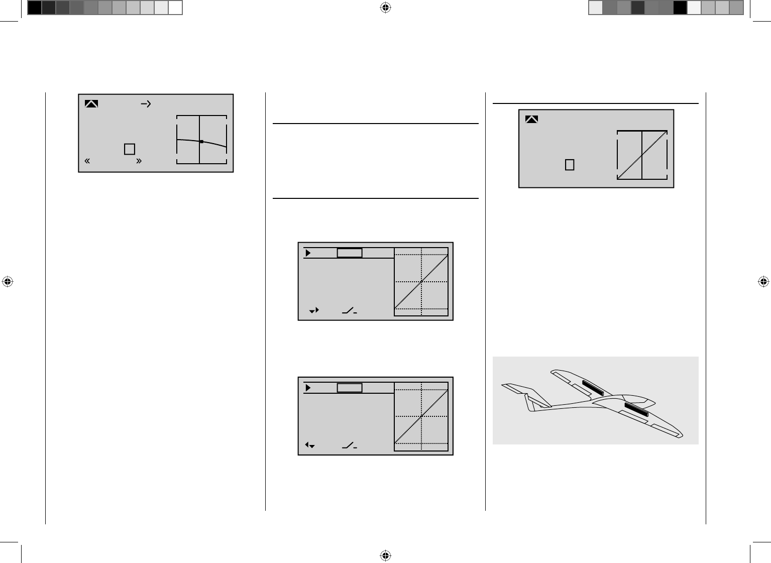
242 Detail program description - Control adjust
Input
Output
Point 1
–19%
–6%
–7%
Brake
Normal
EL
Curve on
After exiting the "Brake settings", the "Aileron
differentiation" can be set:
This serves to eliminate the negative torque. The
downward defl ected aileron normally generates a higher
level of resistance during the fl ight than when defl ected
upward the same distance, whereby the model is pulled
to the "wrong" side. In order to prevent this, with the
input of a differentiation of the travel of the respective
servo defl ected downward is reduced accordingly. A
value between 20 and 40 %, in this case, seldom arises,
however, the "correct" setting must be sought.
The option "AI ¼ RU" (Aileron ¼ rudder) also serves
a similar purpose, as well as for the comfortable control
of a model. A value around 50 % is a practical value
to start with. However, this function should be made
switchable with the assignment of a switch if you ever
have aerobatic fl ight ambitions. (The author, for example,
switches off this mixer "automatically" when switching
to the "Speed" fl ight phase, in which he assigns both
options to the same switch accordingly.)
The last option of the "Wing mixers" menu, "EL ¼ AI"
mixer, is not currently of interest.
If the model-specifi c settings were made thus far,
the initial start can be considered. If course, at fi rst
you should perform a "dry run", meaning you should
carefully check all the settings once again on the
ground. Incorrect programming can damage more than
just the model! In case of doubt, ask the advice of an
experienced model pilot.
If you should fi nd during the testing that one or multiple
settings must be made for the adjustment of the rudder
effects to your control habits, the control throws are too
long or short on the whole, you should adjust this in the …
""Dual Rate / Expo" menu (page 108)
… to your own requirements and habits.
With "Dual Rate" the relationship of the joystick travel to
control travel is adjusted, see page 108:
100%
100%
100%
Ail
Ele
Rud
DUAL
–––
–––
–––
SEL
On the other hand, if the maximum throws are OK and
only the reactions around the center position are to
strong for more sensitive controls, then the "exponential"
functions comes (additionally) into play:
0%
0%
0%
EXPO
–––
–––
–––
SEL
Ail
Ele
Rud
If a switch is also assigned, switching can even take place
between two dual-rate/expo settings during the fl ight.
This is similar for the option …
"Channel 1 curve" (page 116)
Input
Output
Point ?
0%
0%
0%
C1
normal
Curve
Curve off
With this option, one or multiple points of the control
curve of the throttle/brake joystick can be infl uenced in
such a way that a pleasant or even purposeful behavior
is guaranteed.
An example of this would be the "dead" travel of
spoilers. The fl aps fi rst pass through this after a certain
"idle travel" of the brake joystick from the wing. With a
corresponding "bending" of the curve, the "dead' travel
is covered more quickly. The spoilers come out from
the wing earlier and then the remaining travel can be
controlled with greater sensitivity. (This also applies for
the control of a motor in the same manner, which can be
controlled through C1 as an alternative.)
After this, you must defi ne the behavior of the receiver in
the event of a failure in the …
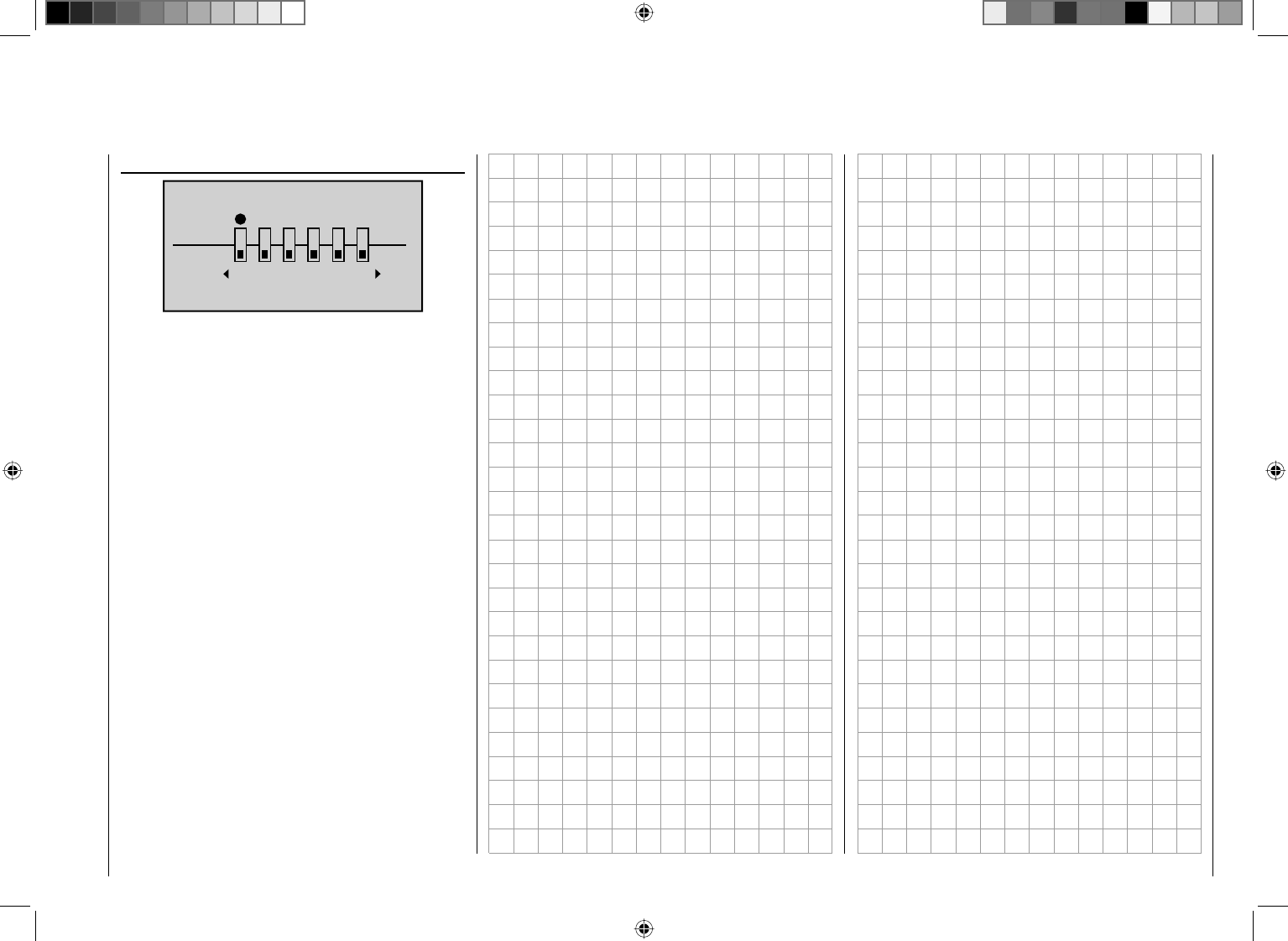
243
Detail program description - Control adjust
"Fail safe" menu (page 196)
FAIL SAFE
Pos
hold
123456
DELAY : 0.25s STO
… because "doing nothing" is the worst thing which can
be done for a winged model.
In the transmitter's home position, "Hold" is specifi ed
and "Hold" means that the receiver continuously sends
the last correctly recognized control impulse to the
servos in the model. In the best case scenario the
model fl ies straight ahead for an indefi nite amount of
time and then hopefully "lands" somewhere without
causing signifi cant damage! However, if something like
this happens in the wrong place at the wrong time, the
model ma y become uncontrollable and "tear" across the
fl ight fi eld completely out of control, putting the pilot and/
or spectators at risk. Therefore, it would obviously be
benefi cial to program the the function "Motor off" at the
very least, in order to prevent such risks.
With electro gliders, on the other hand, the fail-safe
setting "motor off" can also be used, for example, for
outlanding, to reliably stop the motor or its propeller
by immediately switching off the transmitter after the
landing.
The author usually prefers a "braking fi nish" within
eyeshot to fl oating off "somewhere else".
244 Detail program description - Control adjust
Integration of an electric drive into the model programming
An electric drive can be controlled in different ways:
The simplest method to integrate one such drive into
the model programming is with the use of a throttle/
brake joystick (C1). However, since this is already
specifi ed for the brake system in the course of the model
programming described above, either the switchable
solution described beginning on page 247 or even the
use of an alternative control is possible.
As such, one of the two three-stage switches CTRL 9
or 10 is better suited than the proportional rotary control
CTRL 6 ... 8. (Unlike rotary controls, switches can be
operated with one fi nger without having to release
the joystick). An alternative would also be one of the
two-stage switches. Basically, the switch should be
positioned conveniently within reach.
Before we turn to the individual examples, it is important
must be noted that all inputs in the Control adjust menu
can be selectively programmed as fl ight-phase specifi c
("PH" in the "Type" column) or model memory specifi c
("GL" in the "Type" column)!
However, since the drive should usually be available
depending on the current fl ight phase, we recommend
leaving the standard default "GL" ("global") in the "Type"
column which your are using.
Input 5
offset
0%
0%
0%
–––
0%
Input 6
Input 7
Input 8 –––
–––
–––
GL
GL
GL
GL
typ
A common option in the following examples 1 ... 5, the
automatic tracking of the elevator trimming in the power
fl ight, should also be mentioned at the beginning of this
section:
If it becomes apparent after the initial power fl ights
that the model must be continuously corrected with the
elevator while the motor is switched on, this situation
can be corrected by setting a free mixer and adjusting it
accordingly. For this purpose, switch to the menu ...
""Free mixers"
… and program one of the linear mixers M1 … 8 or, if
applicable, also one of the curve mixers K9 … 12 from
"channel controlling the motor" according to "Ele", e. g.
of "8 ¼ Ele":
typ fr to
M1
M2
M3
8EL
M4
M5 ?? ??
?? ??
?? ??
?? ??
On its second screen page, the required – usually
low – correction value is entered:
L.MIX 1
0%
Offset
ASY
SYM
8EL
Mix input
+4% +4%
Notice:
The adjustment of a curve mixer is described in detail in
the section "Channel 1 curve" starting on page 116.
Example 1
Use of a proportional rotary control
CTRL 6 … 8
If one of these controls is used, the connection is very
simple. Only the motor controller (speed control) has to
be connected to a free servo connection 5 ... 12 of the
receiver.
Bear in mind that, depending on the model type and
number of aileron and fl ap servos, the output 2 + 5 or 6
+ 7 are already linked.
Therefore connect your speed controller to the next free
input and assign the selected input – for example, "Inp.
8" – one of the proportional rotary controls CTRL 6 ... 8.
For example, CTRL 7. This is carried out in the menu ...
""Control adjust" (page 96)
With the arrow keys cd of the left or right touch pad,
select the desired line. Then, by pressing the central
SET key of the right touch pad, you active the "Switch
and control assignment". Now turn the knob of the
proportional rotary control. After a short time, the entry,
e.g.
"Control 7", appears in the inverse fi eld.
245
Detail program description - Control adjust
the selected control close to "Full throttle" so that the
marking frame is only placed around one value fi eld.
Now enter a value of at least 1 s, ...
Input 5
– time +
0.0
0.0
0.0
1.0
Input 6
Input 7
Input 8
0.0
0.0
0.0
0.0
normal
… with which a movement of the proportional control
in the "ON" on direction which is too fast is processes
move gently, and you can check immediately this by
switching to the "Servo display".
Notice:
No delay is entered on the "OFF" side, so that the •
drive can be switched off instantly at any time. This
does not additionally stress the drive, because it
merely "runs down".
If you have defi ned fl ight phases in the "•Phase
setting" and "Phase assignment" menus, the
settings described above must be made in the same
manner for each active fl ight phase. Otherwise, you
may wonder why the drive motor begins running at
half power after a phase change, but does not react
to movements or the rotary knobs …
The adjustment of the appropriate control travel and
directions for the motor control (speed controL) is
normally carried out in the "Control adjust" menu in the
"- Travel +" column. Alternatively, you can also carry out
these settings in the menu ...
Input 5
offset
0%
0%
0%
–––
0%
Input 6
Input 7
Input 8
–––
–––
GL
GL
GL
GL
typ
Ct7
Since the drive should usually be available depending
on the current fl ight phase, if applicable, you should
leave the standard default "GL" in the "Type"
column – as already mentioned earlier in this section.
If applicable, for the necessary adjustment of the
appropriate control travel for the motor control (speed
control), use one of the arrow keys to switch to the right
from the "Offset" column to the "- Travel +" column.
typ fr to
M1
M2
M3
8EL
M4
M5 ?? ??
?? ??
?? ??
?? ??
If you now switch to the eServo display" by
simultaneously pressing the keys of the left touch pad
and then actuate the rotary control, you will see the
columns of Channel 8 "wander from one side to the
other and back.
However, if you rotate the proportional rotary control
too fast – in practice – the resulting abrupt motor start-
up can briefl y strain the entire drive string. You should
defi nitely counteract this effect ahead of time with an
appropriate value in the "Time" column for such cases.
Therefore, using one of the arrow keys, switch one
column to the right, to the "Time" column and then move
""Servo adjustment" (page 90)
S4
S5
S6
Rev centr +
trv
0%
0%
0%
100% 100%
100% 100%
100% 100%
0%
0%
100% 100%
100% 100%
S7
S8
.
Example 2
Use of a three-stage switch CTRL 9 or 10
This variant realizes a three-stage speed setting, such
as Motor OFF, "half" and full power.
A corresponding motor control (speed control) is
required on the receiver side.
The required settings are basically the same as those
described under Example 1. Therefore, the same
comments and recommendations also apply.
Apart from the infi nitely variable motor control under
Example 1 and the three-stage motor control in this
example, the selection of the two control types only has
an effect on the type of clock control, see page 252.
Notice:
By shifting the neutral position and then adjusting the •
travel so that the offset value on the side to which the
neutral point was shifted is subtracted from the travel
and added to the other, the "Half throttle position"
can be infl uenced in the "Control adjust" menu.
Therefore, with an offset value of -20 %, for example:
+80 % on the minus side of the travel setting and
+120 % on the plus side and vice versa.
If you have defi ned fl ight phases in the "•Phase
246 Detail program description - Control adjust
setting" and "Phase assignment" menus, the
settings described above must be made in the same
manner for each active fl ight phase. Otherwise, you
may wonder why the drive motor begins running at
half power after a phase change, but does not react
to movements or the switch …
Example 3
Use of a two-stage switch SW 2, 3 or 8
This variant realizes a purely ON/OFF function.
On the receiver side, either a simple electronic
switch or – if a gentle motor start-up, for example, is
desired – an appropriate motor control (speed control)
is required.
With the exception of the assignment of a different
control, the settings required for this are essentially the
same as those described under Example 1. Therefore,
the same comments and recommendations also apply.
Apart from the infi nitely variable motor control under
Example 1 and the two-stage motor control in this
example, the selection of the two control types only has
an effect on the type of clock control, see page 252.
Only the type of representation of the selected switch in
the dispay of the menu …
""Control adjust" (page 96) differs from the
description there.
Input 5
offset
0%
0%
0%
–––
0%
Input 6
Input 7
Input 8 –––
–––
–––
GL
GL
GL
GL
typ
Like with example 1, you also switch to the line of a free
input, activate the "Control and switch assignment" in
the third column and then move the selected control,
in this case Switch "2" from the desired Motor OFF
position to Motor ON.
In this case – as already mentioned earlier in this
section – you leave the standard default "GL" in the
"Type" column.
The setting of the appropriate control travel for the
motor control (speed control) is made in the "- Travel +"
column. If the motor should up gently with the use of a
motor control (speed control), an appropriate delay time
can be set – as described in Example 1 – in the "- Time
+" column:
Input 5
– time +
0.0
0.0
0.0
1.0
Input 6
Input 7
Input 8
0.0
0.0
0.0
0.0
normal
All other settings - as already mentioned earlier in
the example - take place analogously to Example 1.
Therefore, the same comments and recommendations
apply.
Notice:
No delay is entered on the "OFF" side, so that the •
drive can be switched off instantly at any time. This
does not additionally stress the drive, because it
merely "runs down".
If you have defi ned fl ight phases in the "•Phase
setting" and "Phase assignment" menus, the
settings described above must be made in the same
manner for each active fl ight phase. Otherwise, you
may wonder why the drive motor begins running at
half power after a phase change, but does not react
to movements or the switch …
247
Detail program description - Control adjust
Control E-motor and crow alternatingly with C1 joystick
Example 4
Before we discuss the programming of this fourth
example or turn the to the expansion of the previously
described basic programming, a few words should be
said about the position of the throttle/brake joystick
with "Motor OFF" or "Brake OFF". Normally the C1
control joystick is moved forward for the throttle control
and backward for the extension of the brake. If, in this
"classic" assignment, you switch to the brake system
with Motor "OFF" (= joystick "back"), for example,
"full brake" would be applied after the switch time you
specifi ed in the "Phase setting" menu, or vice versa,
if you switch to drive with the "brake retracted" the
motor would be switched to "full power" within this time
range...
A "glider pilot" can make the best of this
"Emergency" – normally with "brake retracted = front" –
by switching to motor "ON" only if necessary and then
the power decreases, if applicable (and hopefully you
will not forget to push the C1 joystick "forward" again
when switching back). A typical "motor pilot", on the
other hand, operates in the opposite manner, only
switching to the brake if necessary, etc... You can also
combine the "Zero point" of both systems to avoid
confusion, whereby a "glider pilot" would tend prefer the
"front" and a "motor pilot", on the other hand", would
likely prefer the "rear".
Whatever the case may be, the mc-32 HoTT
transmitter enables both variants. In the following text,
however, the combination of the two "OFF" positions
to "front" is assumed. However, if you have a different
preference, it is not a problem: The only difference
from the described version lies in the logical selection
of "Throttle min rear/front" and, if applicable, of a
SEL
vorne
–90%
STO
Tail type
Motor at C1
Aile/flaps 2AIL
M O D E L T Y P E
Brake Off In 1
Normal
In the process, if the offset point is not placed
completely at the end of the control travel, the remainder
of the travel is "idle" up to this limit. This idle path
ensures that all brake settings remain at "neutral", even
with minor deviations from the limit of the brake fl
ap
control. At the same time, the effective control path is
automatically spread to 100 %.
For this reason, in the next step it must be ensured that
the infl uence of the C1 joystick on the motor can be
infl uenced. For this purpose, switch to the menu ...
"Phase setting" (page 128)
... and assign a meaningful name, such as "normal",
from the list for "Phase 1" after activation of the selection
fi eld in the "Name" column. The asterisk in the second
column indicates which phase is currently active.
As long as no phase switches are assigned, this is
always Phase 1. Give "Phase 2" the name "Landing" in
accordance with the example.
In the "Ph.Tim" column you can assign a so-called fl ight
phase timer for the measurement of the motor running
time and/or the gliding times as necessary for each
phase. You could, for example, assign one of the "Timers
1 ... 3" to the "Normal" fl ight phase in order to measure
the total motor run time through the C1 joystick:
corresponding brake offset in the menu ...
""Model type" (beginning on page 82)
Here you fi rst specify in the "motor" line whether the
throttle minimum position (= Motor "OFF" position)
should be at the "front" or "rear" - as already discussed:
In the following programming example, "Motor OFF" and
"Brake OFF" are combined at "front":
Tail type
Motor at C1
Normal
Aile/flaps 2AIL
M O D E L T Y P E
Brake Off In 1+100%
SEL
front
Notice:
With the selection of "Throttle min front/rear" the
trimming will then only have an effect in the "idle"
direction of the motor and is not the same as with the
"none" entry, having the same effect at every position of
the C1 joystick. Since the C1 trimming is not normally
used with electric drives, however, this has no further
relevance.
You adjust the "according to your model, in this case
"normal".
In the "Aileron/fl aps" line you enter the correct number
of aileron and fl ap servos – in this example "2 AIL".
In the last line you leave the standard entries for the
selection of "Brake retracted = rear". On the other hand,
if you prefer "Brake retracted = front", select the "Brake
offset" line and defi ne the offset point – as described on
page 83 – as "front":
248 Detail program description - Control adjust
menu. For example, you name the phase for the front
switch position "normal" and "landing" for the rear
position (or vice versa):
PHASE ASSIGNMENT
A B C D E F
2
prior
combi
2 Landing
These phase names then appear in all fl ight-phase
dependent menus and, of course, also in the base
screen of the transmitter.
Now switch to the "Landing" fl ight phase and in the
"Crow" line of the submenu ...
""Brake settings" (page 160)
Elevat curve
BRAKE SETTINGS
AILE
Crow
D.red 0%
0%
0%
0%
0%
WK WK2
Landing
0%
… of the "Wing mixers" menu, set the desired throw of
the ailerons with actuation of the C1 joystick ("brake")
upward. Then, if applicable, switch to the "FL" column
in order to specify the desired through of the fl
aps with
C1 actuation downward (hidden in the fi gure above).
This fl ap position is referred to as "Crow position" or
"Butterfl y; see also page 160.
In the line "D.red" (differentiation reduction), enter a
value which corresponds to the value you entered or
enter on the fi rst page of the "Wing mixers" menu in the
Pha1
Pha2
Pha3
Name Sw.time
Pha4
Pha5
Normal
Strecke
–
–
–
–
¾
Landing
1.1s
0.1s
0.1s
0.1s
1.1s
Then you must assigned these two fl ight phases to a
switch with which you can switch between the two fl ight
phases during the fl ight. In this case, a single switch is
suffi cient. It should be easy to reach, however, so that
you can still switch between "motor" and "brake" during
a landing approach, for example, without having to
release a joystick.
The assignment of the selected switch takes place in the
menu ...
"Phase assignment" (page 134)
Select the switch symbol under "C" with one of the arrow
keys. After briefl y pressing the central SET key of the
right touch pad, actuate the desired switch, such as
"SW 2".
PHASE ASSIGNMENT
A B C D E F
1 Normal
2
prior
combi
Both switch positions, in other words ON (I) and OFF ( )
are initially assigned in the bottom right of the display to
the phase "1 normal". With one of the arrow keys, select
this value fi eld and then, by briefl y pressing the central
SET key of the right touch pad, activate the selection list
of the phases which you set up in the "Phase setting"
Pha1
Pha2
Pha3
Name ph.Tim.
Pha4
Pha5
Normal
Strecke
–
–
–
–
¾Clk 1
Landing
Then the timer is controlled through a corresponding
control switch to be defi ned on the C1 joystick. As soon
as you switch to the "Landing" fl ight phase, this fl ight
phase timer is automatically stopped and hidden in the
base screen. More about this can be found on page 142.
Now move the marking frame over the "Ph.Tim" column
to the "Motor" column to the right. Here you can decide
with "yes/no" in which phase the motor is controlled by
the throttle/brake joystick and the brake system to be
adjusted in the "Brake settings" submenu of the "Wing
mixers" menu should be shut off (= "yes") and vice
versa (= "no"):
Pha1
Pha2
Pha3
Name motor
Pha4
Pha5
Normal
Strecke
–
–
–
–
¾yes
Landing no
Now move the marking frame once more to the right and
enter an appropriate switching time after activation of
the value fi eld of the "Sw.Time" column; for example:

249
Detail program description - Control adjust
line "Aile.diff."
With the "Elevat curve" mixer the normally occurring
"Upward tilting" of the model on the raising of the
ailerons can be automatically suppressed. The suitable
correction values for the respective value must be
tested out through fl ight. Set this mixer so that the fl ight
speed of the model does not change too much with the
brake system extended in comparison with the "normal"
fl ight speed. Otherwise, there is the risk, among other
things, that the model plunges when the brake system
is retracted, e. g. for the extension of a landing approach
which is too short.
If everything is correctly set so far, only the motor is
controlled with the C1 joystick in the "normal" fl ight
phase, whereas this should be switched off in the
fl ight phase "landing" (Servo 1 in "Servo display"
independently of "Throttle min front/rear" to -100% or
adequately for a servo travel setting deviating by 100
%, if necessary). In this fl ight phase the C1 joystick
then only controls the raising of the ailerons and, if
applicable, the lowering of the fl aps with the neutral
point in the C1 control position selected per offset.
250 Detail program description - Control adjust
C1 joystick switchable between E-motor and spoiler
Example 5
If, contrary to the assumptions of the preceding Example
4, the model has additional spoilers or only spoilers,
they can be incorporated into the control of the model by
means of the following programming.
For this purpose, program the menus "Model type",
"Phase setting" and "Phase assignment" in the same
manner as described under Example 4. The settings
described there in the "Brake settings" submenu of
the "Wing mixers" menu, on the other hand, are only
relevant if you would like to use an additional crow
system in parallel to your spoilers.
With the settings described under Example 4, the
control of the E-motor and, if applicable, that of a
crow system will function as usual. Only the control
of a spoiler connected to Output 8, for example, must
additionally be programmed. For this purpose, switch to
the menu …
"Control adjust" (page 96)
… and switch to the fl ight phase "normal". Now, using
the arrow keys, switch to the "Offset" column of the
line "Inp. 8". After activation of the value fi eld by briefl y
pressing the central SET key of the right touch pad,
change the offset value in the now inverse value fi eld of
Input 8 until your spoilers are "retracted" again:
Input 5
offset
0%
0%
0%
Input 6
Input 7
Input 8 –––
–––
Normal
–––
–––
–100%
Confi rm this setting by briefl y pressing the central ESC
key of the left key pad or the central SET key of the right
touch pad and then switch to the center column to the
left. Now switch to the fl ight phase "Landing" and then
briefl y press the central SET key of the right touch pad.
The display shows the window ...
Input 5
offset
0%
0%
0%
–––
–100%
Eing. 6
Eing. 7
Input 8 –––
–––
–––
Move desired switch
or control adj.
Landing
Now move the C1 joystick As soon as this is recognized,
"Ct1" appears in the display instead of "---":
Input 5
offset
0%
0%
0%
Input 6
Input 7
Input 8 Ct1
–––
Landing
–––
–––
–100%
Leave the offset value in this fl ight phase
to "0 %". If necessary, however, you may have to change
the leading symbol of the travel setting to reverse the
control direction by switching the travel setting from
+100 % to -100 % in the "Travel" column.
Now we are practically fi nished. Check the programming
in the "Servo display" menu, which you can reach from
the base screen of the transmitter as well as nearly
every other menu position by simultaneously pressing
the keys ef of the left touch pad. You will discover that
"Servo 1" (motor control) is controlled in the "normal"
phase and in the "landing" phase only the spoiler is
controlled at "Servo 8" and, if applicable the aileron and
fl ap servos – just as we intended.

251
Detail program description - Control adjust
252 Detail program description - Control adjust
SEL
0%
0%
0%
C1
C2
C3
–––
C4
CONTROL SWITCH
–85%
STO
–––
–––
–––
Ct1
In order to assign the control switch you just crated to
the desired timer, switch to the menu ...
""Timers (gen.)" (page 138 … 141)
…, and, with the arrow keys, select the line "Top", to
which the "Tim(ers)" are assigned by standard. In this
line, move the marking frame over the "Timer" column to
the right, to the column above the switch symbol, using
the appropriate arrow key of the left or right touch pad.
Now press the central SET key of the right touch pad
twice: Pressing once activates the switch assignment
and tapping again opens the list of the "expanded
switches":
Model time
Akkuzeit
Oben:
Mitte: Flug
Alarm
–––
0:34h
1:23h
0s
0s
Stopp –––
–––
SEL
Control/fix sw
C1 C2 C3 C4 FX
FXi C1i C2i C3i C4i
Now select the previously programmed control switch,
Ct1 in the example, and assign it to the timer by briefl y
pressing the central SET key of the right touch pad:
Model time
Batt. time
Top :
Centr:Flight
Alarm
–––
0:34h
1:23h
0s
0s
Stop C1
–––
SEL
The timer in the base screen now starts with movement
of the C1 joystick toward full throttle and stops if you pull
the C1 joystick back over the switching point.
Example 1 of the preceding pages
If you have decided to continue with the model
programming described on the previous pages in
Example 1 on page 244, fi rst switch to the menu ...
"Control switches" (page 123)
… and select the line of a control switch which has not
been assigned yet with the arrow keys. After activation
of the control assignment by briefl y pressing the central
SET key of the right touch pad, the following window
appears:
SEL
+75%
0%
0%
G1
G2
C3
–––
C4
CONTROL SWITCH
Gb1
Gb1
–75%
STO
–––
–––
–––
Move desired
control adj.
Now simply move the respective proportional rotary
control, e.g. CTRL 7, from the motor "OFF" position in
the motor "ON" direction.
The switch to the column above STO using the
appropriate arrow key and move the selected control
near the motor "OFF" position and define the switch
Examples 4 and 5 of the preceding pages
If you have decided to continue with the model
programming on described on the previous pages for
Example 4, page 247 or 5, page 250 or you intend to
use the C1 joystick (throttle/brake joystick) for the power
regulation completely independently of this example
programming, you can use a control switch for the
automatic starting and stopping of the timer. For this
purpose, fi rst switch to the menu …
"Control switches" (page 123)
… and select the line of a control switch which has not
been assigned yet with the arrow keys. After activation
of the control assignment by briefl y pressing the central
SET key of the right touch pad, the following window
appears:
SEL
+75%
0%
0%
G1
G2
C3
–––
C4
CONTROL SWITCH
Gb1
Gb1
–75%
STO
–––
–––
–––
Move desired
control adj.
Now simply move the C1 joystick (throttle/brake joystick)
from the motor "OFF" position in the motor "ON"
direction.
The switch to the column above STO using the
appropriate arrow key and move the C1 joystick near the
motor "OFF" position and defi ne the switch point at the
selected position by briefl y pressing the central SET key
of the right touch pad. The switch status is shown to the
right of the control number:
Timer confi rmation with control or switch
253
Detail program description - Control adjust
point at the selected position by briefl y pressing the
central SET key of the right touch pad. The switch status
is shown to the right of the control number:
SEL
0%
0%
0%
C1
C2
C3
–––
C4
CONTROL SWITCH
–85%
STO
–––
–––
–––
Ct6
Notice:
Now place the switching point; but do not put it at the
limit position of the control, because safe switching is
not assured when doing so.
Ct1 used in the example here should be "closed" in the
"full throttle" direction and "open" below the switching
point.
Now switch to the menu ...
""Timers (gen.)" (page138 … 141)
…, and, with the arrow keys, select the line "Top", to
which the "Tim(ers)" are assigned by standard. In this
line, move the marking frame over the "Timer" column to
the right, to the column above the switch symbol, using
the appropriate arrow key of the left or right touch pad.
Now press the central SET key of the right touch pad
twice: Pressing once activates the switch assignment
and tapping again opens the list of the "expanded
switches":
Model time
Akkuzeit
Oben:
Mitte: Flug
Alarm
–––
0:34h
1:23h
0s
0s
Stopp –––
–––
SEL
Control/fix sw
C1 C2 C3 C4 FX
FXi C1i C2i C3i C4i
Now select the previously programmed control switch
"Ct1" and then press the central SET key of the right
touch pad.
Model time
Batt. time
Top :
Centr:Flight
Alarm
–––
0:34h
1:23h
0s
0s
Stop C1
–––
SEL
The timer in the base screen now starts with movement
of the proportional rotary control toward full throttle and
stops if you pull it back over the switching point.
Examples 2 and 3 of the preceding pages
If you control your motor with a switch, on the other
hand, you do not need the described control switch
described above. It is completely suffi cient if you assign
the same switch to the timer, so that it also begins to run
when you switch on the motor.
Tip:
If the motor run time for an E-model is limited by the
battery capacity, you can have the stopwatch count
down. Enter the maximum permissible motor run time
in the "Timer" column, e.g. "5 min", and briefl y before
the expiration of the permissible time, e. g. "30 s" before,
have the transmitter issue an acoustic warning signal:
Model time
Batt. time
Top :
Centr:Flight
Timer
–––12:34h
1:23h
0:00
Stop 5:00
Model time
Batt. time
Top :
Centr:Flight
Alarm
–––
0:34h
1:23h
0s
Stop C3
–––
SEL
30s
254 Detail program description - Control adjust
Servos running in parallel
A second servo running in parallel is often required,
such as when brake fl aps or spoilers installed in the
wings or the left and right elevator or a double fi n should
be actuated by a servo or a large rudder fl ap should
be simultaneously controlled by two servos due to high
throw forces.
In principle, this task could also be solved by connecting
the servos together on the model side using V-cable.
However, this has the disadvantage that the servos
combined in this manner can no longer be adjusted
individually and separately from the transmitter – the
advantage of a fi nely tuned adjustment of the respective
servos to one another by a computer remote steering
system would no longer be provided. This is similar
for the so-called "Channel Mapping" described in the
scope of the "Telemetry" menu: In comparison to the
adjustment possibilities of the transmitter, there are also
limitations with this process.
The fi rst example, therefore, describes the coupling of
two brake or spoiler servos, the second describes the
operation of two or more throttle servos and the third
describes the coupling of two elevator servos.
The "two rudder servos" example on the next page
describes the coupling of two rudder servos, whereas
Variant 1 is preferable for applications of this type,
because with the use of a "cross-mixer", because this
is quicker and easier to program. Contrary to this, the
second variant, also permits asymmetric and/or non-
linear curves with the use of the "Free mixer" menu.
Two brake or spoiler servos
For the operation of your brake fl aps and/or spoilers in
each wing half you have installed a servo and kept the
default linear control characteristics unchanged in the
"Channel 1 curve" menu.
Then connect one of the two servos to Output 1,
provided for this purpose by standard, and the second
to an arbitrary free receiver connection 5 ... 12, such as
Output "8". Now switch to the menu …
" Control adjust" (page 96)
… and, using the arrow keys, assign the "Control 1" in
the line of Input 8:
Input 5
offset
0%
0%
0%
–––
0%
Input 6
Input 7
Input 8
–––
–––
GL
GL
GL
GL
typ
Ct1
Leave the standard settings for the remaining values.
If necessary, carry out the required servo travel
adjustments in the "Servo adjustment" menu. There
you can also adjust the travel of servo 1 and 8 to one
another, if necessary.
Important notice:
If you have defi ned fl ight phases in the "Phase setting"
and "Phase assignment" menus, the settings must be
made in the same manner for each active fl ight phase.
Otherwise, you may wonder why only one spoiler can
be moved as intended and the other remains in its half
extended position …
Multiple-motor aircraft
As described above, a model can also be operated with
two or more motors.
The fi rst throttle servo and/or the fi rst motor control is
connected as usual to (receiver) Output 1 and each
additional throttle servo and/or each additional motor
control is connected to a free (receiver) Output 5 ...
12. The inputs of the corresponding assigned control
channels are then each assigned to Control 1; for
example :
Input 8
offset
0%
0%
0%
0%
Input 9
Input10
Input11
GL
GL
GL
GL
typ
Ct1
Ct1
Ct1
Ct1
Important notice:
Since the motor control unit should be available
regardless of a currently active fl ight phase, make sure
to leave the standard default "GL" in the "Type" column.
Two elevator servos
Two elevator servos should be switched in parallel.
According to the receiver assignment plan, see page 57,
the receiver output 8 is intended for the connection of
the second elevator servo.
This would be taken into account on the software side in
the preconfi guration of a corresponding mixer. You can
fi nd this in the ...
"Model type" menu (page 82)
In this menu switch to the "Tail" line using the arrow
keys, activate the value fi eld by briefl y pressing the
central SET key of the right key pad and select the entry
"2ELSv3+8":
255
Detail program description - Control adjust
Tail type
Motor at C1 None
Aile/flaps 1AIL
M O D E L T Y P E
Brake Off In 1+100%
SEL
2ELSv3+8
Then carry out the fi ne-tuning of the travel of the two
servos "as accustomed" in the "Servo adjustment"
menu.
Two rudders
We want to switch two rudders "in parallel". The second
rudder is located at the free receiver output 8.
Variant 1
In the menu …
"Cross-mixer" (page 194)
… select one of the cross-mixers and enter "8" and "RU"
in its left and center value fi elds, as shown in the fi gure:
Ty p Diff.
zu
DUAL MIXER
Mixer1
Mixer2
8
Mixer3
Mixer4
?? ??
?? ??
?? ??
0%
0%
0%
0%
RU
The same defl ection "cc", which would take place
through "Input 8" may not have an effect here. Therefore,
you should make absolutely sure in the …
"Control adjust" menu (page 96)
Input 5
offset
0%
0%
0%
–––
0%
Input 6
Input 7
Input 8
–––
–––
GL
GL
GL
GL
typ
normal
–––
… that "Input 8" is set to "free" so that the control
function is separate from the control channel.
Alternatively, You can set Input 8 in the "Only mix
channel"to "no control", regardless of the fl ight phase,
by setting Channel 8 to "only mix":
MIX ONLY CHANNEL
only
normal
789
10 11 12
Variant 2
With this variant a mixer, "Tr Rudd 8" should be set in
the menu …
" Free mixers " (page 181)
¼. In the "Type" column, select the setting "Tr" so that
the rudder trimming affects both rudder servos:
ty fr to
M1
M2
M3
RU 8
?? ??
M4
M5
?? ??
?? ??
?? ??
Tr
Then switch to the graphic screen and set a symmetric
mixture of +100%.
L.MIX 1
0%
Offset
ASY
SYM
RU 8
Mix input
+100% +100%
"Input 8" should also be programmed to "free" here in
the "Control adjust" - in all fl ight phases, if applicable.
However, control function "8" can be separated from
control channel "8" more easily in the fl ight-phase
independent menu "Only mix channel", page 193:
MIX ONLY CHANNEL
only
normal
789
10 11 12
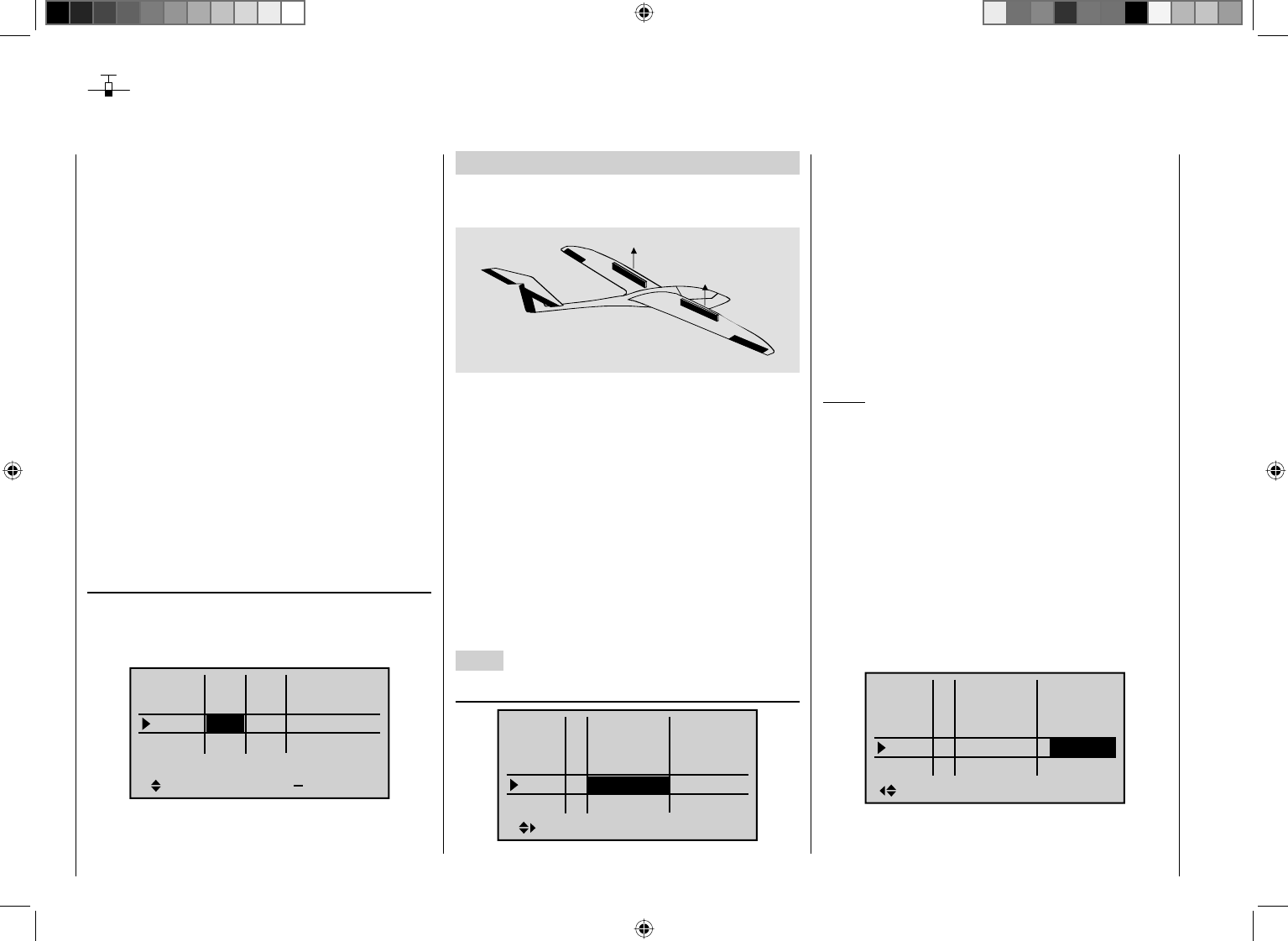
256 Detail program description - Control adjust
Use of fl ight phases
Up to seven different fl ight phases (fl ight statuses)
can be programmed with settings independent of one
another within one of the model memories.
Each of these fl ight phases can be called with a switch
or a switch combination. This makes it possible to switch
between different settings for the various fl ight statuses,
such as "Normal", "Thermal", "Speed", "Distance", etc.,
simply and conveniently. However, with the fl ight phase
programming you can also make slight modifi cations,
e. g. of mixers, to try out by switching during the fl ight in
order to fi nd the optimal settings for each model more
easily.
Before you begin with the actual programming of
fl ight phases, you should consider whether the digital
trimming of transverse, altitude and side should have
be "global" – in other words, the same for all fl ight
phases – or per "Phase" – in other words, each fl ight
phase is individually variable.
If you decide in favor of a phase-specifi c trimming of the
elevator, for example, switch the menu …
"Joystick setting" (page 92)
… and change the standard "global" default accordingly.
The same applies for the number
of trimming steps in the column "St":
Tr +
4
4
4
0.0s
0.0s
0.0s
40.0s
0.0s
0.0s
0.0s
0.0s
GL
GL
GL
St
PH
Ch.1
Aile
Elev
time
Rudd
Example 1 ...
… continuing with the previous programming of an
electric glider with 2 aileron servos.
AI
AI
EL
RU
The control of the E-drive takes place independently of
the C1 joystick with one of the two proportional rotary
controls CTRL 7 or 8 or with one of the two three-stage
switches CTRL 9 or 10. The motor control is connected
to receiver Output 9 according to the description
beginning on page 244 and Examples 1 and two which
serve as the basis of this continuation. In the "Model
type" menu, therefore, "None" was selected in the
"Motor to C1" line, which has the consequence, among
other things , that the "Motor" column in the "Phase
setting" menu is hidden and the "Brake settings"
submenu of the "Wing mixers" menu is available
without limitation.
1. Step
"Phase setting" (page 128 )
Pha1
Pha2
Pha3
Name ph.Tim.
Pha4
Pha5
¾
+
+
Normal
Thermal
Speed
+
–
Launch
Initially, one or multiple fl ight phases are provided with
a specifi c identifi cation ("Name") for the respective
fl ight status. This identifi cation has no infl uence on the
programming of the transmitter; it only serves for an
improved differentiation of the individual fl ight phases
and is shown later in all fl ight-phase dependent menus
and in the base screen.
The selection of the respective line, a name and the
setting of the switching time take place, as "usual", by
pressing the corresponding key(s) of the two four-way
touch pads.
Notice:
With the exception of Phase 1, which should always
be assigned with the name "Normal" since it is
always active, if the fl ight phases are deactivated, it is
completely irrelevant which name is assigned to which
phase!
In everyday use by a model pilot, three to a maximum of
four fl ight phases are usually completely suffi cient:
"Start" with the climb settings•
"Thermal" for "Flying high",•
"Normal" for normal conditions and •
"Speed" for high gear.•
In the "Sw.time" column (switching time) ...
Pha1
Pha2
Pha3
Name Sw.time
Pha4
Pha5
¾
+
+
Normal
Thermal
Speed
+
–
3.0s
2.0s
4.0s
0.1s
Launch 1.0s
… you can defi ne the time for the "cross-fading" when
switching from any other fl ight phase to this one in order
257
Detail program description - Control adjust
to enable a "smooth" transition of the various servo
positions. Thus, an increased stress of the model under
certain circumstances with a "hard" change of rudder
or fl ap positions, for example, is prevented The "Status"
column shows you the currently active fl ight phase with
an asterisk "¾".
2. Step
In order to actually be able to switch between the
individual fl ight phases, the assignment of one or
multiple switches is necessary. One of the two three-
stage switches (CTRL 9 or CTRL 10) is best suited for
switching of up to three fl ight phases.
Each of the two switch limit positions is assigned to
one of the fl ight phase switches A ... F, starting from
the center position. The assignment of the switch takes
place in the menu ...
"Phase assignment" (page 134)
First select "C" with the marking frame. The briefl y press
the central SET key of the right touch pad and move
the switch from the center position to a limit position, for
example, downward:
PHASE ASSIGNMENT
A B C D E F
1 Normal
267
prior
combi
Move the switch back to the center position and then
select "D", and after activation of the switch assignment,
move the switch to the other limit position, for example,
to the top:
PHASE ASSIGNMENT
A B C D E F
1 Normal
267
prior
combi
Now the three-stage switch is programmed.
Now and additional switch could be assigned for the
"start" fl ight phase, if applicable. In this case under "A",
so that the "start" phase is always switched to from
every other fl ight phase in parallel to the switching-on of
the motor:
A B C D E F
1 Normal
267
PHASE ASSIGNMENT
prior
combi
Then the respective switch positions must be assigned
corresponding fl ight phases (names). Although you have
already assigned names for some fl ight phases, the
phase name "1 normal" still appears in the right of the
display; see the figures above.
First move the three-stage switch to the limit position,
for example to the top, and switch with the marking
frame in the display down to the right to the value fi eld
for the fl ight phase name. Briefl y press the central SET
key of the right touch pad for the activation of the input
fi eld and select the desired fl ight phase for this switch
position, in this example "2 Thermal", with the arrow
keys:
A B C D E F
267
2 Thermal
PHASE ASSIGNMENT
prior
combi
Proceed in the same manner for the other switch limit
position, which is assigned the name "3 Speed".
If applicable move Switch 2 and assign this switch
combination the name "4 Start".
Briefl y pressing the central ESC of the left touch pad or
the central SET key of the right touch pad completes the
time name assignment.
The flight-phase dependent model settings made before
the assignment of phase switches are now in the flight
phase "1 Normal". This is the phase which is called
with the open "Start" switch in the center position of the
three-stage switch.
3. Step
In order to not have to carry out all previously made
settings for the model in the "new" fl ight phase from
the ground up, we recommend fi rst copying the already
tested programming of the fl ight phase "Normal" to the
other fl ight phases. This is carried out in the menu …
"Copy / Erase" (page 64)
=>
=>
=>
=>
=>
=>
=>
Copy flight phase
Erase model
Copy model–>model
Export to SD
Import from SD
258 Detail program description - Control adjust
Here, select the menu item "Copy fl ight phase" with the
arrow keys and then briefl y press the central SET key of
the right touch pad.
In the appearing window, "Copy from phase", "1 Normal"
is selected ...
7
Copy from phase:
3
5=>
=>
2
4
6
1Normal Thermal
Speed Launch
… and then briefl y press the central SET key of the
right touch pad, whereby the display switches to
"Copy to phase". Now the target is selected (initially "2
Thermal") and confirmed by pressing the central SET
key of the right touch pad again. After confi rmation of
the subsequent safety query, all settings are copied
according to the selection.
Proceed in the same manner with the other two phases
("1 Normal" to "3 Speed" and "1 Normal" to "4 Start").
4. Step
Now three or four phases are programmed, the settings
are also copied and there is even a "soft" transfer, but ...
there are still no fl ight-phase specifi c settings.
Now, if applicable, in order to adapt the fl ap positions to
the different requirements of the individual fl ight phases,
in the menu ...
"Control adjust" (page 96)
… the standard default "GL" is fi rst changed to "PH" for
"Phase" in the type column:
Input 5
offset
0%
0%
0%
–––
0%
Input 6
Input 7
Input 8
–––
–––
PH
GL
GL
GL
typ
Normal
–––
Then switch to the "Offset" column and make the
settings deviating from the "Normal" fl ight phase for the
ailerons. However, switch to the desired fl ight phase
beforehand, whose name is shown at the bottom in
the display, appropriate to the switch position. Both
positive and negative throw changes are possible. These
settings are to be made separately for each fl ight phase:
Input 5
offset
0%
0%
–––
0%
Input 6
Input 7
Input 8
–––
–––
PH
GL
GL
GL
typ
Normal
–––
–7%
5. Step
Any necessary phase-specifi c trimming of the elevator is
made with the help of the digital trimming of the elevator
joystick. This requires that you have at least set the
elevator trimming to "Phase" in the "Joystick setting"
menu - as already shown in this programming example.
Alternatively, you can also carry out these settings in the
"Phase trim" menu ...
Normal
¿
0%
ELEV
Thermal
0%
QR
Launch
Thermal
Speed
0%
0% 0%
0% 0%
0%
6. Step
In the menu …
"Wing mixers" (beginning on page 146)
… the fl ight phase name of the newly activated fl ight
phase appears at the bottom edge of the display. If
the switch position is now changed, the name of the
flight phase selected with the switch appears, but
with the previously copied settings of the fl ight phase
"Normal". Here you set you values phase-specifi cally
for the aileron differentiation, the share of the mixture
of transverse to side, and if applicable, also a mixture
of altitude to transverse. (The latter increases the agility
over the transverse axis when "Turning".)
Aile.diff.
Brake sttings
AI 55%
WING MIXERS
EL FL 0%0%
–––
–––
RU
Thermal
33%
Notice:
The list of displayed options depends on the number of
servos entered in the "Ailerons/flaps" line in the "Model
type" menu.
Now switch to the submenu …
259
Detail program description - Control adjust
Elevat curve
BRAKE SETTINGS
AILE
Crow
D.red
+30%
+33%
0%
0%
0%
0%
WK WK2
Normal
… and enter how wide the ailerons should be raised in
the "Crow" line.
With "D.red" (differentiation reduction), you should enter
the value previously set in the aileron differentiation line
in order to suppress it again while breaking.
In the "Elevat curve" submenu, enter a correction value
for the elevator, see page 162.
Notice:
The "Brake settings" submenu of the "Wing mixers"
menu is switched "off" if "yes" is entered for the current
fl ight phase in the "Model type" menu, page 82 "Motor
at C1 front/rear" and in the "Motor" column of the
"Phase setting" menu, page 128. Change the fl ight
phase, if applicable.
260 Detail program description - Control adjust
Example 2 …
Glider with four fl ap wings, two large fl aps and tow
coupling
AI
FL
FL
AI
EL
RU
The following example is based on the assumption that
you have already mechanically preadjusted the model
and you have already ensured the correct defl ection of
all rudders or checked this again in the scope of this
programming and made adjustments, if applicable,
through servo switching at the receiver and/or through
the "Servo setting" menu.
This programming example is based on an assignment
of the receiver connections in accordance with the
following diagram:
Receiver power supply
Free or aux. function
Free or aux. function
Aileron or left aileron
Elevator or left rudder / elevator
2nd airbrake servo or 2nd elevator or aux. funct
Receiver power supply
1st airbrake servo
Right aileron
Flap or left flap
Right flap
Aero-tow release or free or aux. function
Free or aux. function
Rudder or right rudder / elevator
Begin with the new programming of the model in a free
model memory location.
In the menu "Base setup model", connect your receiver
to the transmitter, enter a model name and select or
check, if applicable, the stick mode. Later, before the
fl ight operation, also activate the range test in this menu.
In the menu …
"Model type" (page 82)
… leave "Motor to C1" at "None" and the tail type at
"Normal". In the "Aile/fl ap" line, on the other hand, set "2
AIL 2 FL".
In the "Brake" line, program or leave "In1", because the
brake and spoiler fl ap servos connected to 1 + 8 should
be activated later with the corresponding C1 joystick as
the control:
Tail type
Motor at C1
Normal
None
Aile/flaps 2AIL2FL
M O D E L T Y P E
Brake Off In 1+90%
SELSTO
The setting in the "Brake offset" value fi eld defi nes
the neutral position of all mixers of the "Brake settings
submenu of the "Wing mixers" menu. Place this neutral
point at approx. +90%, insofar as the brake fl aps should
be retracted in the front position of the C1 joystick. The
remaining path between +90 % and the full throw of
the joysticks, +100 %, is then assigned as idle travel.
This assures that the rudders or fl aps addressed by
the mixers of "Brake settings" remain in their "Normal"
position, even with slight deviations from the limit
position of the C1 control. At the same time, the effective
control path is automatically spread to 100 %.
In the menu …
"Control adjust" (page 96 )
… assign a switch to Input 9, for example, for the
operation of the tow coupling. In order for this switch
to work independently of the fl ight phase, leave the
standard default "GL" in the "Type" column of this input.
With "– Travel +" you can adjust the control travel for the
switching of the switch:
Input 6
offset
0%
0%
0%
–––
0%
Input 7
Input 8
Input 9
–––
–––
GL
GL
GL
GL
typ
9
By simultaneously pressing the keys ef of the left
touch pad, the setting in the "Servo display" can be
checked.
Since the C1 control should actuate Servo 8
simultaneously with Servo 1, establish this link through
the menu "Control adjust".
For this reason, also switch to the line before and assign
"Control 1" to Input 8.
Input 5
offset
0%
0%
0%
–––
0%
Input 6
Input 7
Input 8
–––
–––
GL
GL
GL
GL
typ
Ct1
However, please note in this connection, that a non-
linear control curve programmed in the "Channel 1
Use of fl ight phases
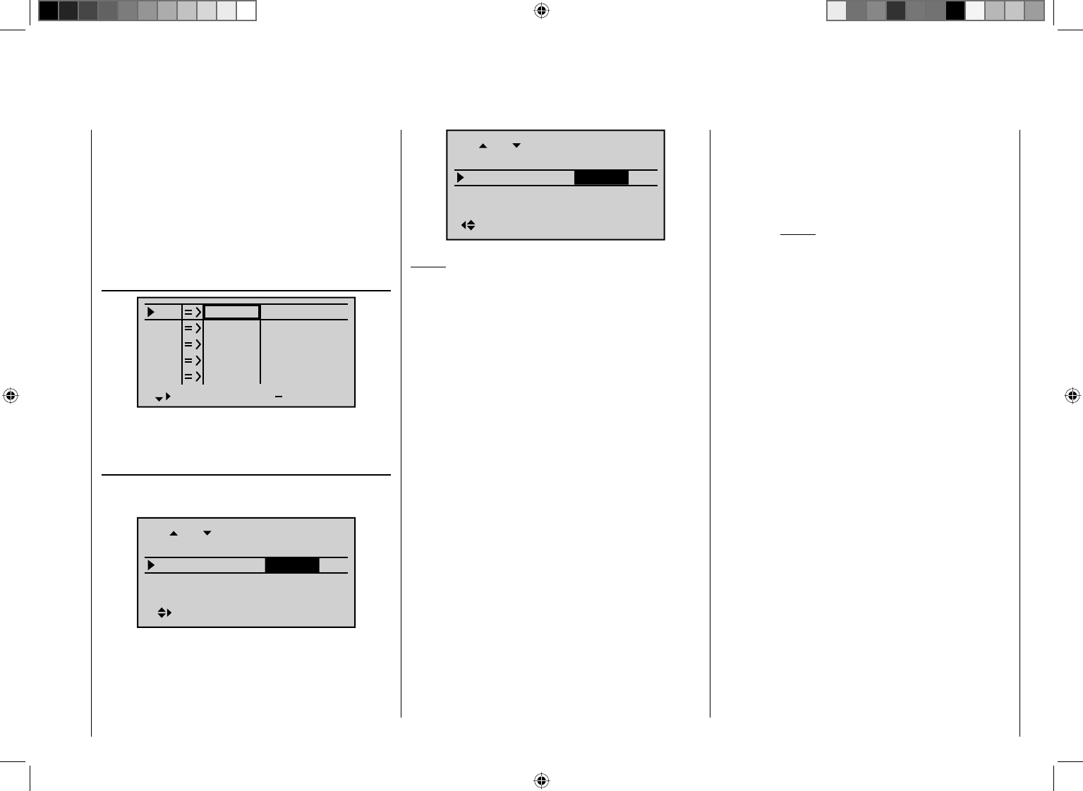
261
Detail program description - Control adjust
curve" menu has as little effect on this input as brake
offset set to less than 100 %, which you can check very
easily in the "Servo display" menu. You can reach this
from nearly every menu position by simultaneously
pressing the keys ef of the left touch pad:
The travel and, if applicable, the directions of rotation
of the spoiler servos 1 and the second spoiler servo
connected to Output 8 can be adjusted in the menu …
Servo adjustment (page 90)
S1
S2
S3
Rev cent +
trv
0%
0%
0%
100% 100%
100% 100%
100% 100%
0%
0%
100% 100%
100% 100%
S4
S5
...
In the Multi-fl ap menu of the ...
"Wing mixers" menu (beginning on page 146)
… you now enter the fi rst mixer values for the four wing
fl aps; for example:
0%
fl.pos
AILE
Diff.
Ail-tr
AI +100%
+100%
+50%
0%
FLAP
Diff.
+66%
+66%
+33%
fl.pos
Ail-tr
AI
Notice:
The parameter values shown here are model-dependent
and must be determined by test fl ights.
In the …
cAId line you define the percentage with which
the two fl ap pairs "AI and "FL" should follow
the aileron control. Also check whether the
ailerons are defl ected in the right direction
during the adjustment of the parameter
values.
The adjustment range from -150 % …
+150 % enables the correct throw direction
adjustment regardless of the direction of
rotation of the servos.
Ail-tr Here you determine the percentage with
which the aileron trimming should affect the
AI and FL.
Diff. Here you specify the differentiation of the
aileron control on the AI and FL fl aps. For
the signifi cance of the differentiation, see
page 148.
The adjustment range from -100 % …
+150 % enables the correct differentiation
direction adjustment regardless of the
direction of rotation of the aileron and fl ap
servos.
fl .pos. In this line you set the fl ight-phase specifi c
fl ap positions for all fl aps available on the
respective model. In the process, you can
determine the positions the fl aps assume for
each fl ight phase.
Notice:
The values appearing in this line are based
on the same data set as in the comparable
position in the "Phase trim" menu, which
is why changes always take effect in both
directions.
cFLc Since all inputs in the "Control adjust"
menu are set to "free" by default, neither the
ailerons nor the fl aps can be actuated in this
standard setting. In this respect, you also
leave the default entry here.
However, if you would like to be able to
vary the fl ap positions with a switch or
proportional rotary control by the position
specifi ed in the "fl .pos." line, assign the
desired control to Input 6 in the "Control
adjust" menu and set the desired reaction to
the movement of the control selected for this
purpose over the percentage in this lane.
EL¼FL This mixer incorporates the ailerons (AI) and
fl aps (FL) with elevator actuation.
The mixing direction is to be selected so that
all fl aps are defl ected downward with the
elevator pulled up and defl ected upward with
the elevator pushed down (= hydroplane).
The mixing proportion is normally in the low
double-digit range.
Now switch to the "Brake settings" within the "Wing
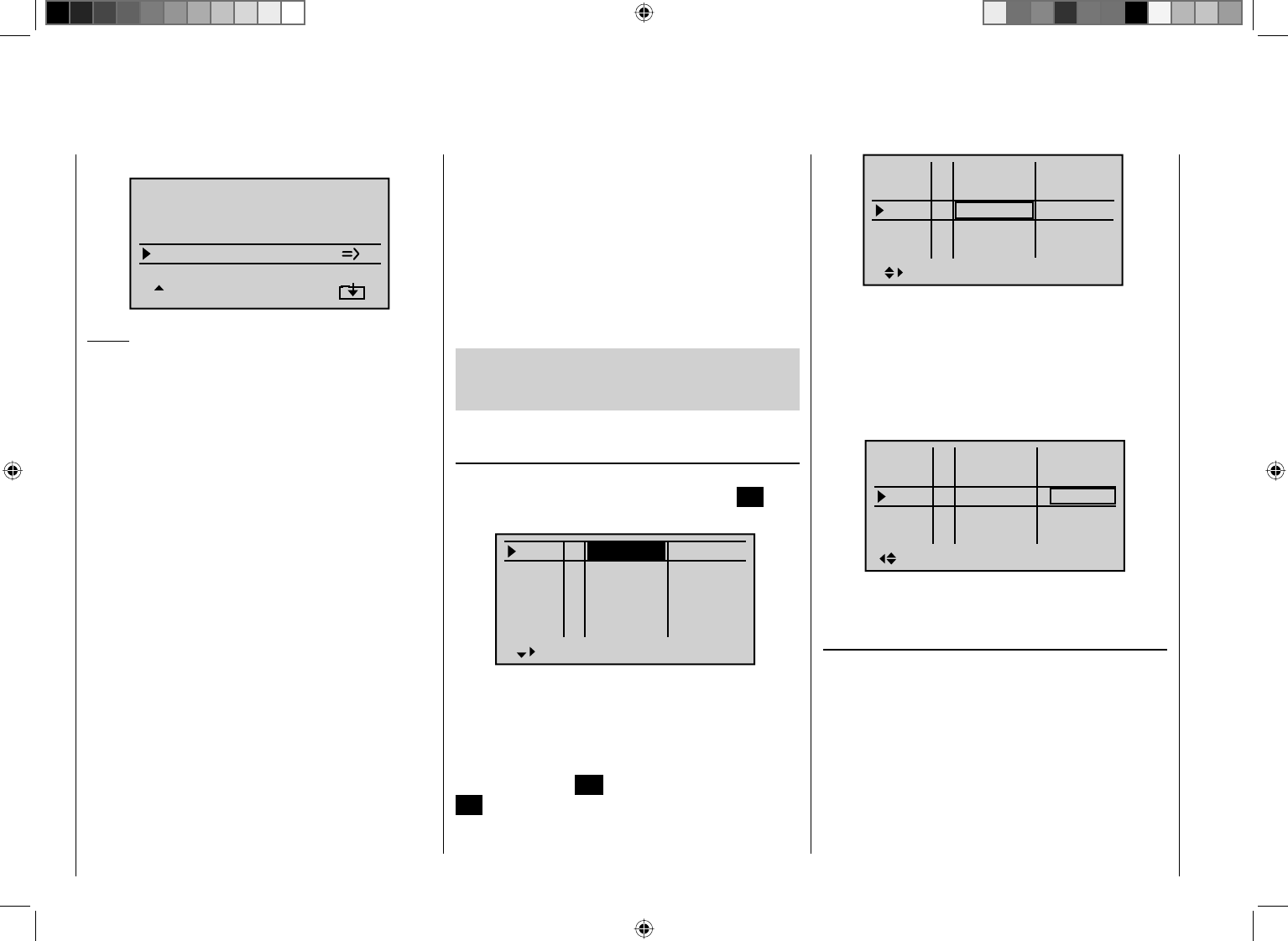
262 Detail program description - Control adjust
mixers" menu ...
Elevat curve
BRAKE SETTINGS
QR
Crow
D.red
+44%
+77%
0%
+66%
0%
+55%
WK WK2
Notice:
The "Brake settings" menu is switched "off" if "yes"
is entered for the currently active fl ight phase in the
"Model type" menu, page 82, "Motor to C1 front/rear"
and in the "Motor" column of the "Phase setting" menu,
page 128. If applicable, switch to the fl ight phase
Crow Further above we designated the C1 joystick
for the brake fl ap control.
In this line you determine the share with
which the AI and FL should be included
on actuation of C1 in the manner that both
ailerons are defl ected "slightly" upward and
both fl aps are defl ected as far downward as
possible.
By simultaneously pressing the keys ef of
the left touch pad, you switch to the "Servo
display" menu so that you can observe
the servo movement and, in particular, that
there is no infl uence on the fl aps above the
adjusted brake offset, e.g. +90 %, up to the
throw limit of the controller C1; see above
("Idle travel" of the C1 joystick).
D.red In the line "Differentiation reduction" you
should enter the value previously set in
the ailerons differentiation line in order to
suppress it again during braking.
Elevat curve In this line you set another correction
value for the elevator, see page 162.
Insofar as necessary, check and adjust all fl ap throws,
the servo center, the servo travel and the travel limitation
through the menu "Servo adjustment".
It may also be time to start the initial fl ight testing,
insofar as all global settings - that is to say, all fl ight-
phase independent settings - are completed.
Two additional fl ight phases should be set up in
the following, each of which requires a somewhat
different fl ap position.
Therefore, switch to the menu …
"Phase setting" (page 128)
… and activate the assignment of phase names in the
"Name" column by briefl y pressing the central SET key
of the right touch pad:
Pha1
Pha2
Pha3
Name ph.Tim.
Pha4
Pha5
normal
Start
Strecke
–
–
–
–
¾
Now give Phase 1 - the "Normal phase" - that is also
the phase which includes the previous settings, the
name "Normal", which you select with the arrow keys.
Phase 2 receives the name "Thermal" and Phase 3
receives the name "Speed". Now conclude your entry by
briefl y pressing the ESC key of the left touch pad or the
SET key of the right touch pad:
Pha1
Pha2
Pha3
Name ph.Tim.
Pha4
Pha5
Normal
Thermal
Speed
–
–
–
–
¾
Now move the marking frame over the column "ph.Tim."
to the right to the column "Sw.time" and set a "switching
time" from any other phase to the respective phase in
order to avoid an abrupt phase change ; in other words
erratic changes of fl ap positions. Now try out different
switching times. In this example we have specifi ed 1 s in
each case:
Pha1
Pha2
Pha3
Name Sw.time
Pha4
Pha5
¾
+
+
Normal
Thermal
Speed
–
–
1.0s
1.0s
1.0s
0.1s
0.1s
Now assign the corresponding switches for these fl ight
phases in the menu ...
"Phase assignment" (page 134)
… with which you can switch between the three phases.
Since no special priority is necessary, assign the switch
"C", for example, in the display and select one of the two
limit positions of one of the two three-stage switches,
CTRL 9 or 10 as the switch. Then move the selected
switch back to the center position, activate the switch
assignment under "D" and move the selected three-
stage switch from its center position to the other limit
position in order to:
263
Detail program description - Control adjust
PHASE ASSIGNMENT
A B C D E F
1 Normal
267
prior
combi
After the switch assignment is complete, use the arrow
keys to switch to the bottom right and activate the
assignment of phase names by briefl y pressing the
central SET key of the right touch pad.
Now close "SW 7" by moving the selected three-stage
switch upward.
Assign the name "<2 Thermal>" to this switch position
and leave the name "<1 Normal>" in the "OFF position"
of this switch.
PHASE ASSIGNMENT
A B C D E F
267
prior
combi
2 Thermal
PHASE ASSIGNMENT
A B C D E F
267
prior
combi
1 Normal
Then move the three-stage switch down toward "SW
6" and assign the name "<3 Speed>" to this switch
position:
PHASE ASSIGNMENT
A B C D E F
267
prior
combi
3 Speed
The phase names selected in the programming are now
shown, depending on the switch status, in all fl ight-
phase dependent menus, see the table on page 268.
Since we have already made some settings in fl ight-
phase dependent menus, such as in the "Wing mixers"
menu, we will now copy these settings to the "Thermal"
fl ight phase. For this purpose, open the menu ...
"Copy / Erase" (page 64)
… and switch to the "Copy fl ight phase" line:
=>
=>
=>
=>
=>
=>
=>
Copy flight phase
Erase model
Copy model–>model
Export to SD
Import from SD
The maximum seven fl ight phases are listed in "Copy
from phase":
Select the fl ight phase to be copied, 1. "1 Normal".
7
Copy from phase:
3
5=>
=>
2
4
6
1Normal Thermal
Speed
By briefl y pressing the central 2. SET key of the right
touch pad, switch the window to the entry of the
target memory "Copy to phase".
Select phase "2 Thermal" as the target:3.
7
Copy to phase:
3
5=>
=>
4
6
1Normal
Speed
Thermal2
Confi rm the selection by 4. briefly pressing the central
SET key of the right touch pad.
A security query follows, who should be confi
rmed 5.
with "Yes":
Phase to:
to be copied?
NO YES
1 Normal 2 Thermal
Then repeat the process with fl ight phase "3 Speed".6.
Now we will program the required settings in the
fl ight phase "Thermal" as an example.
In order to also be able to vary the camper changing fl ap
position in the "Thermal" phase, in the menu …
"Control adjust" (page 96)
… you assign an operating element to Input 6 – as
described on page 96 .
If you assign one of the two proportional rotary controls
to this input, independent of the fl ight phase if applicable
(CTRL 7 in the example, the ailerons (2 + 5) and camber
264 Detail program description - Control adjust
changing fl aps (6 + 7) are moved continuously with a
mixer proportion to be set in the "Wing mixers menu.
Input 5
offset
0%
0%
0%
–––
0%
Input 6
Input 7
Input 8 –––
–––
Ct7
Normal
If you assign the still free second three-stage switch to
Input 6 instead, you can call three different FL positions
of the ailerons (AIL) and camber changing fl aps (FL) as
well as three elevator positions (Elev) in the "Thermal"
fl ight phase, see the following page. (These three switch
positions correspond to the center position and the two
limit positions of the previously mentioned proportional
rotary control.)
Notice:
The FL and AIL fl ap positions in the two limit switch
positions or in the switch center depend on the value set
in the column "- Travel +" as well as the offset value and
the mixer proportion set in the "Multi-fl ap menu" of the
"Wing mixers" menu, see further below.
We will leave the (control) "- Travel +" at the standard
settings of symmetric + 100 % and the offset value at
0 %. Specifying a symmetric or asymmetric time for
smooth switching between the three switch positions - in
the example "1.0 s 1.0 s" - in the column "- Time +" is
recommended:
Input 5
– time +
0.0
0.0
0.0
Input 6
Input 7
Input 8
0.0
0.0
0.0
Normal
1.0
1.0
In the "Multi-fl ap menu" of the …
"Wing mixers" menu (beginning on page 146)
… change only the values for "FL-pos" and "cFLc" in
the "Thermal" fl ight phase:
FL-pos Here you position the AIL and FL in the
"Thermal" fl
ight phase in case the assigned
control (proportional rotary control or three-
stage switch) is in its neutral or center
position in the fl ight.
cFLc In this line you specify the percentage at
which the aileron and camber changing
fl ap servos should be moved as camber
changing fl aps with the selected control (see
above) or with the three-stage switch:
–9%
+10%
0%0%
+10%
AILE
Thermal
+55%
+100%
+100%
FL
fl.pos
EL FL
Diff.
Ail-tr
AI
–14%
+15%
0%0%
+15%
FLAP
Thermal
+33%
+60%
+60%
FL
fl.pos
EL FL
Diff.
Ail-tr
AI
Simultaneously pressing the key combination cd or
ef of the right touch pad (CLEAR) resets changed
values back to the standard settings.
Notice:
Due to the improved lift distribution, the degree of
mixture should be set so that the camber changing fl aps
are slightly "lower" than the ailerons.
By simultaneously pressing the keys ef of the left
touch pad, you can check the reaction of the AIL and FL
servos with actuation of the selected camber changing
fl ap servo in the "Servo display". (Push the C1 joystick
to the front position so that the "AIL" and "FL" fl ap
positions can be better followed on actuation of the
corresponding control.)
Attention:
With actuation of the ailerons, the bars of the "Servo
display" move in the same way and the opposite
way with the actuation of the camber changing
fl aps:
In the control center position, only •
the – example – "FL-pos." setting of +10 % for the AIL
and +15 % for the FL work.
In the one limit position of the control, AIL and FL are •
back in their neutral position, because the degree
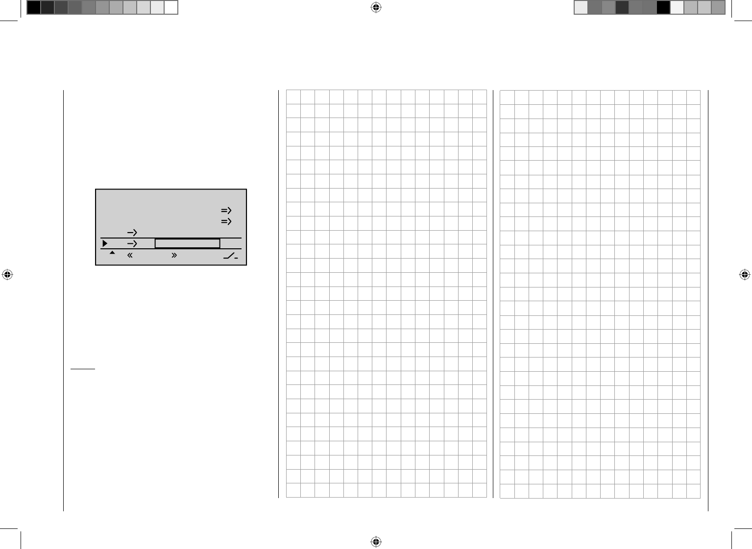
265
Detail program description - Control adjust
of mixture specifi ed for the example compensates
directly for the FL-pos. setting, whereas …
… in the other limit position, AIL and FL reach the •
maximum downward offset prescribed by the mixer
percentage.
In order to set a – corrective – admix for the elevator, exit
the "Multi-fl ap menu" and return to the base screen of
the "Wing mixers" menu:
Brake settings
AI 0%
WING MIXERS
FL EL +5%+5%
–––
–––
RU
Multi-flap menu
Thermal
In the two limit positions of the three-stage switch the
elevator is moved symmetrically in this example with
+5 % (true to side). If, on the other hand, you use a
proportional rotary control, the elevator is defl ected
according to the degree for the control position.
Then make the settings for the "Speed" fl ight phase in
the same manner.
Notice:
The digital trimming of transverse, altitude and side •
work independently of these settings – depending on
the setting selected in the "Joystick setting" menu,
page 92 – "Global" or for each "Phase".
All setting values are model-dependent. Carry out •
the settings on your fi nished model and/or during the
fl ight.
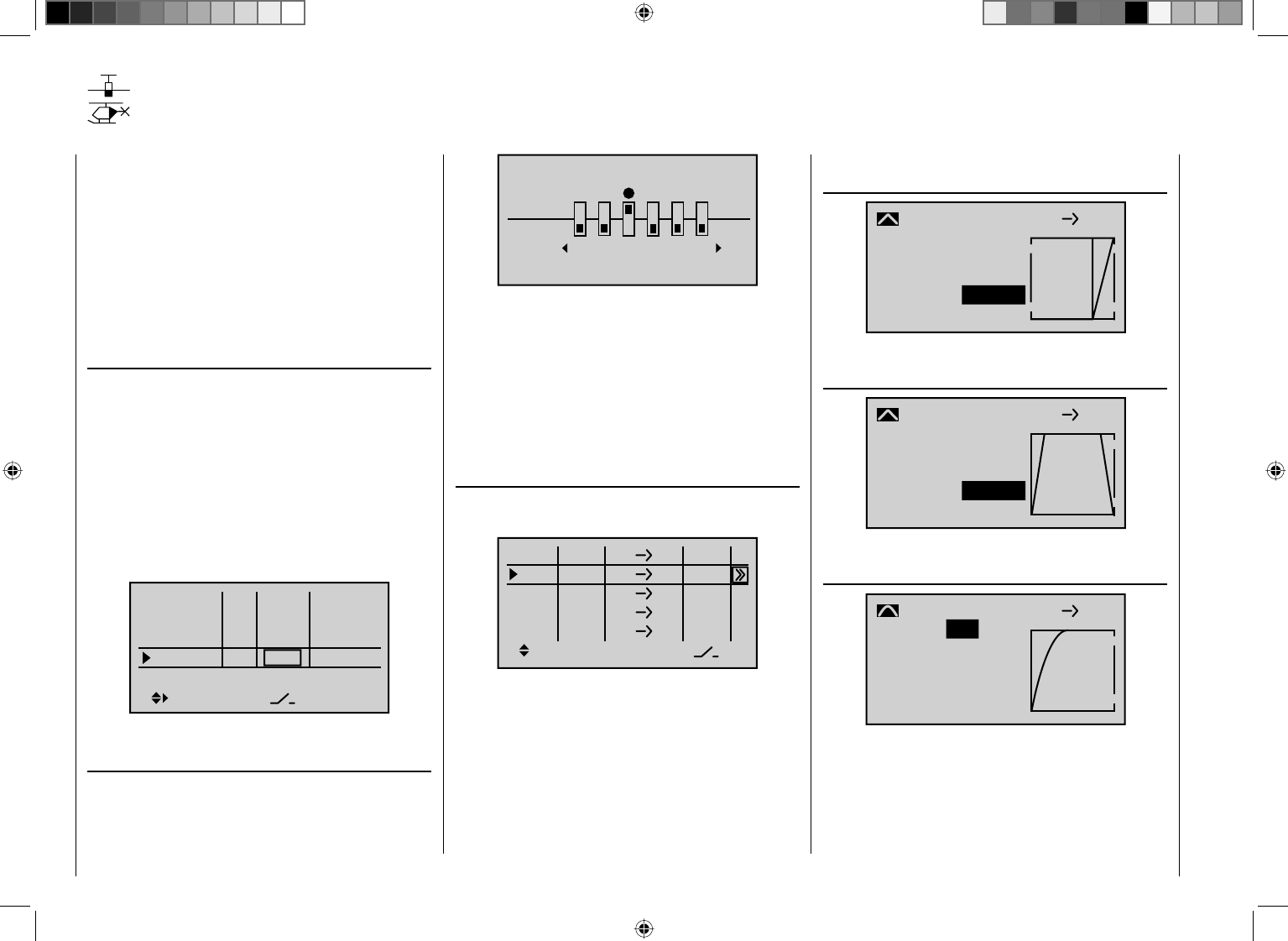
266 Detail program description - Control adjust
Control of temporal processes
using time delay and curve mixers
A useful, but less known capability of the mc-32
HoTT software is the ability to activate nearly any servo
movements with a maximum duration of 9.9 seconds
using a switch.
The programming for this should be shown on the
basis of some examples in the following. Additional
applications can certainly be found once you become
familiar with these capabilities.
The programming is begin in the menu …
"Control adjust" (page 96)
… and in order to be able to approach any point of
the control curve during the programming, fi rst assign
one of the proportional rotary controls to the desired
control channel – in this example CTRL 8 to the Input
9. However, leave the standard default "GL" in the
"Type" column so that this setting is effective for all
fl ight phases analogously to the free mixers to be
programmed in the following.
The input of a time delay in the "- Time +" column should
also be dispensed with initially:
Input 6
offset
0%
0%
0%
–––
0%
Input 7
Input 8
Input 9
–––
–––
GL
GL
GL
GL
typ
Ct8
Then in the menu …
"Only mix channel" (page 193)
… of the selected control channel, "9" in this case, is set
to "Only MIX":
MIX ONLY CHANNEL
only
normal
789
10 11 12
It is mandatory that this is set to "Only MIX", because
the control curves of the curve mixers described in the
following example only function on the output of the
same channel as desired if there is no direct connection
between the control and output! Only then can the linear
control signal be manipulated almost arbitrarily around a
curve mixer and to the appropriate output.
Therefore, in the next step, switch to the menu …
"Free mixers" (page 181)
… and program a curve mixer for the same channel,
e.g. from "9" to "9":
ty fr to
M8
C9
C10
?? ??
99
C11
C12
?? ??
?? ??
?? ??
On this second screen the desired path of the control
curve is then set, whereby the following examples
should only be "food for thought" for the design of your
own control curves.
For example, the control curve could be for …
… delayed lighting of a headlight after the beginning
of the extension of the landing gear:
+50%
–100%
Input
Output
Point 1
C.MIX 9
normal
Curve off
99
–100%
… the control of a landing gear fl ap which closes
again after the landing gear is extended:
–100%
–100%
Input
Output
Point L
C.MIX 9
normal
Curve off
99
–100%
… a smooth motor start-up or the extension of a
self-launch …
–100%
–100%
Input
Output
Point L
C.MIX 9
normal
Curve
99
–100%
on
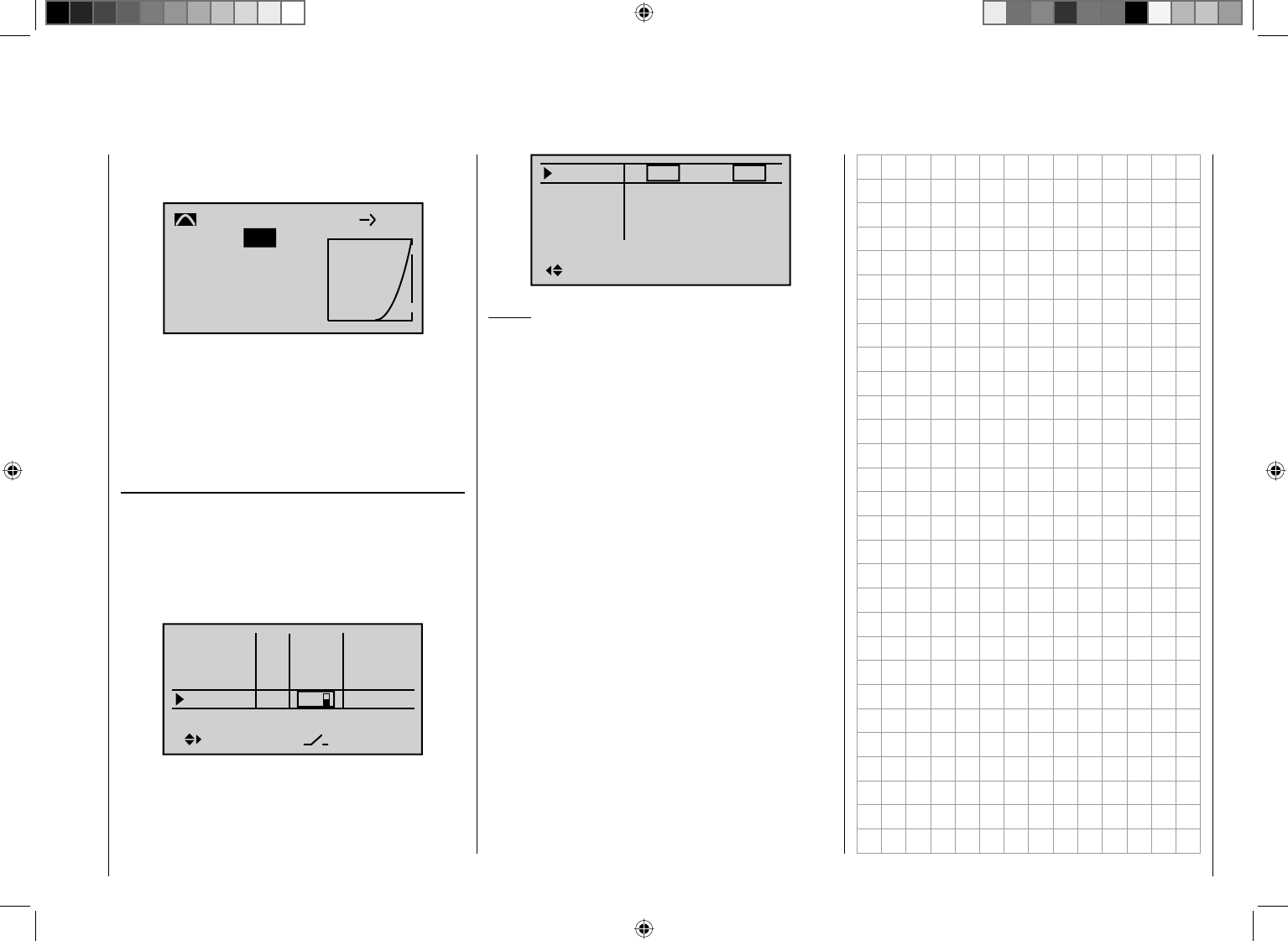
267
Detail program description - Control adjust
… triggered by the same switch, but with a delayed
startup of the drive motor connected to Output 10:
–100%
–100%
Input
Output
Point L
C.MIX10
normal
Curve
910
–100%
on
The function you programmed functions as desired
according to these suggestions – which you can verify
at any time after switching to the "Servo display" by
simultaneously pressing the keys ef of the left touch
pad – then to, complete the programming, an arbitrary
switch, such as "SW 8" is assigned in the menu …
"Control adjust" (page 96)
… to the control channel used instead of the selected
proportional rotary control – in in these examples
"CTRL 8" to channel "9" – and the desired symmetric
or asymmetric time span is set in the "- Time +" column
for the amount of time in which the function should
ultimately take place:
Input 6
offset
0%
0%
0%
–––
0%
Input 7
Input 8
Input 9
–––
–––
GL
GL
GL
GL
typ
8
Input 9
– time +
9.9
0.0
0.0
0.0
Input10
Input11
Input12
9.9
0.0
0.0
0.0
Notice:
In the course of the switch assignment, always bear in
mind that you can also trigger multiple functions with
one switch! For example , with the same switch a landing
gear connected to Output 6 can be started and, as
shown here as an example, the time-controlled landing
gear fl aps connected to Output 9 and/or the headlight,
etc.
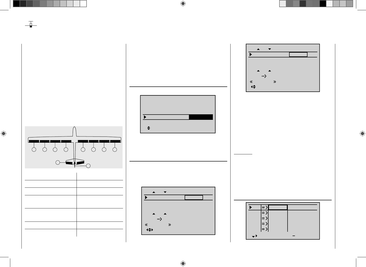
268 Detail program description - Control adjust
Eight-fl ap wing
By standard the mc-32 HoTT supports the
comfortable control of up to eight servos for the aileron/
camber changing fl ap functions.
In the following we will consider a model without motor
drive and without spoilers in the wings. The example
is also based on the assumption that you have already
mechanically preadjusted the model and you have
already ensured the correct defl ection of all rudders or
checked this again in the scope of this programming
and made adjustments, if applicable, through servo
switching at the receiver and/or through the "Servo
adjustment" menu.
The servos should be connected to a suitable receiver
as follows:
7
25
612
11
3
4
910
Rudder Receiver output
Aileron 2 + 5
Aileron 2 11 + 12
Camber changing fl aps
(exterior) 6 + 7
Camber changing fl aps 2
(interior) 9 + 10
Elevator 3
Rudder 4
For the control of all fl aps, up to two additional
proportional rotary controls are required in addition to
the two joysticks or, alternatively up to two two-stage
switches (SW).
In order to be able to control all servos, fi rst switch to the
menu …
"Model type" (page 82)
… and select "4AIL 4FL" in the "Ailerons/fl aps" line.
Tail type
Motor at C1
Normal
None
Aile/flaps 4AIL4FL
M O D E L T Y P E
Brake Off In 1+100%
SEL
In order to also be able to actuate the camber changing
fl ap servos 6 + 7 (FL) and 9 + 10 (FL2), if applicable, in
the Multi-fl ap menu of the menu …
"Wing mixers" (beginning on page 146)
… set the corresponding values for the aileron control of
the two camber changing fl ap pairs in the line "cAILd"
and in the line "Ail-tr." for the adoption of the aileron
trimming:
FL
0%
+100%
fl.pos
EL FL 0%0%
+100%
FLAP
Normal
Diff. 0%
Ail-tr
AI +77%
+77%
0%
+100%
0%0%
+100%
FLAP2
0%
+55%
+55%
FL
fl.pos
EL FL
Normal
Diff.
Ail-tr
AI
You can check the previous settings in the "Servo
display" menu, which you can reach from nearly any
menu position by simultaneously pressing the keys ef
of the left touch pad:
The servos 6 + 7, 9 + 10 and 11 + 12 now move for •
the aileron control exactly like the servos 2 + 5. The
aileron trimming lever also affects all these servos.
The C1 joystick only actuates the servo connected to •
receiver output 1.
Attention:
With aileron actuation the bars of the "Servo
display" move in the same manner and in the
opposite manner with camber changing fl ap
actuation.
The necessary fi ne-tuning of the servos is carried out in
the …
"Servo adjustment" menu (page 90),
S1
S2
S3
Rev cent +
trv
0%
0%
0%
100% 100%
100% 100%
100% 100%
0%
0%
100% 100%
100% 100%
S4
S5
269
Detail program description - Control adjust
… if necessary.
In doing so, the basic programming of the eight-fl ap
wing is completed.
Camber changing fl ap positioning and fl ight changes
First program two or more fl ight phases in the "Phase
setting" and "Phase assignment" menus. On this
occasion, also change the standard default "Global"
to "Phase" in the "Joystick setting", page 92 for the
effect of the digital trimming, if applicable, on your
individual requirements.
An example of fl ight phase programming can be found
on page 256.
One camber changing fl ap setting per fl ight phase
If one camber changing fl ap position per fl ight phase is
suffi cient for you, then in the Multi-fl ap menu" of the …
"Wing mixers" menu (beginning on page 146)
… in the line "FL-pos" adjust the camber changing fl ap
position(s) of the servo pair "AIL" (2 + 5), "AIL2" (11 +
12), "FL" (6 + 7) and "FL2" (9 + 10) to your preferences
in each of the programmed fl ight phases:
–5%
+100%
0%0%
+100%
AILE
+33%
+100%
+100%
FL
fl.pos
EL FL
Thermal
Diff.
Ail-tr
AI
–7%
+100%
0%0%
+100%
AILE2
+33%
+90%
+90%
FL
fl.pos
EL FL
Thermal
Diff.
Ail-tr
AI
–9%
+100%
0%0%
+100%
FLAP
0%
+77%
+77%
FL
fl.pos
EL FL
Thermal
Diff.
Ail-tr
AI
–12%
+100%
0%0%
+100%
FLAP2
0%
+55%
+55%
FL
fl.pos
EL FL
Thermal
Diff.
Ail-tr
AI
Notice:
Whether positive or negative values must be set in the
"FL-pos." line depends on the installation of the servos,
among other things.
Alternatively, if you would like
to set variable camber changing fl ap positions for
each fl ight phase with a proportional rotary control,
… you can additionally vary the basic settings of all
eight fl aps with a single control specifi c to each fl ight
phase.
For this purpose, in the menu ...
"Control adjust" (page 96)
… the inputs 5, 6 and 11 are assigned for each fl ight
phase to the same respective control, for example the
proportional rotary control CTRL 7, and in parallel, the
travel is reduced to approximately 50 % or even less
so that the fl aps can be trimmed with the appropriate
fi ne-tuning. With travel settings differing from one
another, you can also attune the throws of the individual
fl ap pairs to one another specifi c to the fl ight phase in
amenu. For this purpose, you only have to switch the
corresponding inputs from the standard default "GL"
(global) to "PH" (phase):
Input 5
offset
0%
0%
0%
–––
0%
Input 6
Input 7
Input 8 –––
–––
–––
PH
GL
PH
GL
typ
Normal
Input 9
offset
0%
0%
0%
–––
0%
Input10
Input11
Input12 –––
–––
–––
GL
PH
GL
GL
typ
Normal
270 Detail program description - Control adjust
Input 5
– travel +
+25%
+25%
+100%
+100%
Input 6
Input 7
Input 8
+25%
+25%
+100%
+100%
Thermal
Input 9
– travel +
+100%
+100%
+25%
+100%
Input10
Input11
Input12
+100%
+100%
+25%
+100%
Thermal
Notice:
With the use of a switch, set the respective "Deviation"
of the offset point symmetrically or asymmetrically in the
"- Travel +" column.
Elevator compensator with actuation of the camber
changing fl aps
If it should become evident in the flight that a correction
of the elevator is necessary after setting the fl aps, this
correction can be made in the ...
"Wing mixers" menu (beginning on page 146)
Brake settings
AI 0%
WING MIXERS
FL EL 0%0%
–––
–––
RU
Multi-flap menu
Thermal
. For this purpose, select the line "FL ¼ Elev" and enter
an appropriate value independent of the fl ight phase.
If you have assigned the same control to the inputs
5, 6 and 11 – as specifi ed above – all eight fl aps move
simultaneously while the elevator follows the set degree
of mixture.
Camber changing fl ap movement on elevator actuation
Camber changing fl ap movement on elevator
actuation – normally only used in "High gear" to increase
the agility over the transverse axis – is also carried out in
the "Multi-fl ap menu" of the...
"Wing mixers" menu (beginning on page 146)
. Enter the desired fl ight-phase dependent values in the
line "Elev->FL":
–5%
+33%
0%0%
+33%
AILE
+33%
+100%
+100%
FL
fl.pos
EL FL
Thermal
Diff.
Ail-tr
AI
–7%
+33%
0%0%
+33%
AILE2
+33%
+90%
+90%
FL
fl.pos
EL FL
Thermal
Diff.
Ail-tr
AI
–9%
+100%
0%0%
+100%
FLAP
0%
+77%
+77%
FL
fl.pos
EL FL
Thermal
Diff.
Ail-tr
AI
–12%
+100%
0%0%
+100%
FLAP2
0%
+55%
+55%
FL
fl.pos
EL FL
Thermal
Diff.
Ail-tr
AI
In addition to the two camber changing fl ap pairs
(servos 6 + 7 and 9 + 10), the two aileron pairs (servos
2 + 5 and 11 + 12) are now tracked with the degree
of mixture corresponding to the camber changing
flaps -normally opposite the elevator.
Brake settings
Notice:
The "Brake settings" menu is switched "off" if "yes"
is entered for the currently active fl ight phase in the
"Model type" menu, page 82, "Motor to C1 front/rear"
and in the "Motor" column of the "Phase setting" menu,
page 128 . Change the fl ight phase, if applicable.
In the "Brake settings" submenu, which is also fl ight-
phase specifi c, of the "Wing mixers" menu, you can
make the settings so that the aileron pairs 2 + 5 and
271
Detail program description - Control adjust
11 + 12 extend upward and the camber changing fl ap
pairs "FL" (6 + 7) and "FL2" (9 + 10) extend downward,
whereas the elevator is trimmed in parallel to this, see
page 162.
In order for the brake system to react to the C1 joystick
as desired, however, the mixer neutral point (offset) of
the brake system must be adjusted accordingly. This
takes place in the menu …
"Model type" (page 82)
After selection of the line "Brake Off." the C1 joystick is
moved to the position from which the mixer for the brake
system should be set – normally just before the limit
position – and after selection of the appropriate value
fi eld, the set point is defi ned by briefl y pressing the
central SET key of the right touch pad.
If the C1 joystick is not moved over this point toward
the pilot, all mixers of the brake system are carried
along according to their respective degree of mixing.
Below this point the mixer remains inactive, whereas the
selection of "dead travel" is possible.
If the model has additional brake fl aps or spoilers and
your receiver has another free Output 1, you can also
control this through the C1 joystick by connecting the
spoiler servo to receiver Output 1.
However, if you control the left and right spoiler each
with its own servo, and not together, the receiver Output
8 is still available for the connection of the second
spoiler servo. In this case, program the connection to
the second spoiler servo as described in the section
"Servos running in parallel" on page 254.
Reduction of the aileron and camber changing fl ap
differentiation
For the improvement of the aileron effect in the crow
position, you should automatically suppress any
programmed aileron differentiation.
For this purpose, use the "Differentiation reduction"
in the "Brake settings" of the "Wing mixers" menu,
which continuously reduces the degree of the aileron
differentiation to a variable extent when you move the
rudders to the crow position with the C1 joystick. For this
purpose, see page 162.
.
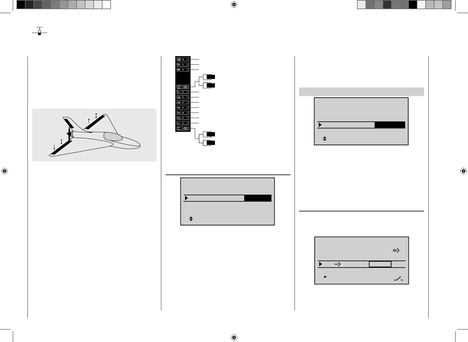
272 Detail program description - Control adjust
Of course, the general comments regarding the
installation and the adjustment of the RC system to a
model at the beginning of the wing model programming
on page 236 also applies for delta and fl ying wing
models! Similarly, the comments for test fl ying and fi ne-
tuning the settings to the programming of flight phases
also apply.
left
right
Delta and fl ying wing models differ signifi cantly from a
"normal" fl ight model due to their unique characteristic
shape and geometry. The differences in the servo
arrangement, on the other hand, are more subtle. For
example, with "classic" delta/fl ying wing models, only
two rudders are normally provided. They are responsible
for both "transverse" and "height/depth", like the side
rudder/elevator function on a V-tail unit.
With more elaborate designs, on the other hand, it
may be the case that one (or two) interior rudders
have only an elevator function and the exterior ailerons
only support the height/depth function, under certain
circumstances. Even with a four or six-fl ap wing the
use of camber changing fl ap functions and/or even a
crow system is now entirely possible. In all these cases,
however, the following assignment of the receiver
outputs should be used, see also page 57. Unneeded
outputs a simply left free:
Receiver power supply
Free or aux. function
Free or aux. function
Right elevon
Right elevon
Free or aux. function
Receiver power supply
Airbrake or throttle servo
or speed controller (electric motor)
Free or aux. function
Free or left flap / elevator
Free or right flap / elevator
Free or aux. function or left flap 2 / elevato
Free or aux. function or right flap 2 / eleva
t
Free or rudder
According to the assignment of the receiver outputs, in
the menu ...
"Model type" (page 82)
None
2AIL
In 1+100%
SEL
Delta/fl
Tail type
Motor at C1
Aile/flaps
M O D E L T Y P E
Brake Off
… the necessary settings are made:
"Motor at C1" "none" or "Throttle min front/rear"
"Tail type" "Delta/fl "
"Aile/FL" "2AIL" (appears automatically).
Insofar as necessary, expand the
default "2AIL" with 1, 2 or 4 camber
changing fl aps ("1FL", "2FL" or "4FL").
"Brake" remains or is only of interest with a
delta or fl ying wing aircraft of the type
"2 AIL 1/2/4 FL". In this case, see
under "Brake offset" on page 83.
Delta and fl ying wing models
These settings specifying the model type affect the
available "Wing mixers" fi rst and foremost. Therefore,
the options are discussed separately for two-fl ap and
multi-fl ap models in the following:
Delta/fl ying wing of the type: "2AIL"
+100%
SEL
Delta/fl
2AIL
None
In 1
Tail type
Motor at C1
Aile/flaps
M O D E L T Y P E
Brake Off
In keeping the standard default "2AIL" in the "Aile./
FL" line, the elevator and aileron control, including the
trimming function, are only mixed automatically on the
software side. On the transmitter side, however, you can
infl uence the effect of the elevator and aileron joystick in
the "Dual Rate / Expo" menu, page 108.
Settings in the menu …
"Wing mixers" (beginning on page 146)
… are, if need be, advantageous with the "AIL ¼ FL"
mixers and are "played' with a great deal of "feel" for the
fl ying behavior with minor differentiation values.
Aile.diff
Brake settings
+10%
AI +50%
WING MIXERS
HR WK 0%0%
–––
–––
RU
normal
Due to the specifi c idiosyncrasies of this model type,
additional settings lead to incompensable moments.
273
Detail program description - Control adjust
FL
0%
0%
fl.pos
EL FL 0%0%
0%
AILE
normal
Diff. 0%
0%
+100%
0%0%
+100%
FLAP
normal
0%
FL
fl.pos
EL FL
Diff.
0%
+100%
0%0%
+100%
FLAP2
normal
0%
FL
fl.pos
EL FL
Diff.
Notice:
Contrary to the separately set aileron trimming, see
below, the trimming is transferred proportionally to the
set mixer value with the mixer "Elev ¼ FL".
The following settings are model-specifi c and may
not be adopted without checking that they are
correct!
In the top line of this "Multi-fl ap menu", analogously to
"normal" four or six fl ap wings, the effect of the aileron
joystick on the aileron, camber changing fl ap and, if
applicable on FL2 is set. In the line "Ail-tr." below this,
on the other hand, the infl uence of the aileron trimming
Delta/fl ying wing of the type: "2 AIL 1 / 2 / 4 FL"
Tail type
Motor at C1 None
Aile/flaps
M O D E L T Y PE
Brake Off In 1+100%
SEL
Delta/fl
2AIL4FL
With delta/fl ying wing constructions with more than
two fl aps, more moments can be compensated for. For
example , the "lifting" moment caused by the raising of
the ailerons (= elevator effect) can be compensated for
with camber changing fl aps lowered correspondingly
wide ( = hydroplane effect).
If you decide in favor of this model type and have
assigned the receiver outputs in accordance with the
connection plan shown above, the aileron function of
the two (exterior) aileron servos will function correctly
immediately, but not the elevator function of the two
aileron servos and, if applicable, the (interior) camber
changing fl aps.
This is achieved with the specifi cation of "2AIL 1/2/4
FL", if the effect of the elevator control, in the "Multi-fl ap
menu" of the ...
"Wing mixer" menu (beginning on page 146)
… is set appropriately in the "Elev ¼ FL" line for
aileron, camber changing fl ap and, if applicable, camber
changing fl ap 2:
on ailerons and camber changing fl aps.
The setting of a differentiation is rather tricker due to the
model type and should only take place based on a feel
for the fl ight behavior of the model.
In the line "cFLc", for the sake of safety, you should
set the standard setting +100 % in the "FL" and, if
applicable "FL2" column – as shown – to 0%:
0%
0%0%
FLAP
normal
0%
0%
0%
FL
fl.pos
EL FL
Diff.
0%
0%0%
FLAP2
normal
0%
0%
0%
FL
fl.pos
EL FL
Diff.
In the "Control adjust" menu, all inputs are set to "free"
by default, but if there is ever confusion in regard to the
assignment of a control ... this has little effect at all.
The last line, "Elev¼ FL", has already been addressed
earlier in this section.
In principle, the author of this manual had programmed
a delta model years ago operated with the mc-20
and a crow system as landing assistance … entirely
without tilting moments through correspondingly attuned
wing mixers "Brake ¼ aileron" and "Brake ¼ camber
changing fl ap", whereby "aileron" refers to the exterior
rudder pair and "camber changing fl ap refers to the
interior rudder pair.
274 Detail program description - Control adjust
In order to now achieve this with the mc-32 Hott,
switch to the "Brake settings" of the …
"Wing mixers" menu (beginning on page 146)
… and enter the values for the ailerons to be raised
and the "fl aps" to be lowered in the "Crow" line so that
the occurring moments compensate one another and
the altitude of the model remains stable. In the process,
however, you should leave the fl aps with enough "play"
for the elevator function!!! Therefore, do not utilize the
entire servo travel for the crow alone; for example:
Elevat curve
BRAKE SETTINGS
AILE
Crow
D.red
+55%
0%
0%
–44%
0%
0%
FLAP FLAP2
Normal
You can ignore all other settings in this menu.
Notice:
The "Brake settings" menu is switched "off" if "yes"
is entered for the currently active flight phase in the
"Model type" menu, page 82, "Motor to C1 front/rear"
and in the "Motor" column of the "Phase setting" menu,
page 128. Change the flight phase, if applicable.
Similarly, a modern, tapered fl ying wing air craft can
also be operated. With some of these models there
are also interior and exterior rudders: The prior is in
front of the center of gravity and the latter is behind. A
downward throw of the central rudder(s) increases the
ascending forces and has an elevator effect. An upward
throw has the opposite effect. On the exterior ailerons,
on the other hand, the effect is just the opposite: A
downward throw shows an elevator effect and vice
versa. With appropriate adjustment of the "leading"
mixer to the setting of curve mixers in order to achieve a
supporting effect from the external rudder pair with only
extreme joystick defl ection in the height/depth direction,
"everything" is possible here. The author of this manual
uses a curve mixer for his model, which is defi ned by a
total of four points:
0%
0%
Input
Output
Point
C.MIX 9
normal
Curve
EL 5
0%
on
In this example the two interpolation points 1 and 2
are each at 0 % as well as the left edge point at +60 %
and the right edge point at -65 %. Then the curve was
rounded by pressing the central SET key of the right
touch pad.
In this case: Regardless of which type of servo
arrangement was selected, any type of differentiation
should be set with caution! On a tail-less model,
differentiations show a single-sided height/depth
elevator effect, so we urgently recommend beginning
at least the initial fl ights with a setting of 0 %! Over
the course of the further fl ight testing, under certain
circumstances it may be advantageous to experiment
with differentiations deviating from zero.
With larger models, rudders in the winglets - the "ears"
mounted on the wing ends - can be benefi cial. If these
are controlled with two separate servos, with the use of
one of the mixers in the menu ...
"Cross-mixer" (page 194)
… the rudder signal can be "split" very easily and even
differentiated, whereby the second rudder servo is
connected to one of the still free receiver outputs. For a
model of the type "Delta/Nf", the receiver output "5" may
still be free, and we want to use it in the following:
Ty p Diff.
zu
DUAL MIXER
Mixer1
Mixer2
5 RU
Mixer3
Mixer4
?? ??
?? ??
?? ??
0%
0%
0%
+66%
In this case a differentiation is necessary, because
the respective exterior rudder fl ies over a larger curve
radius than the interior rudder, which is comparable to
the wheel position of the front wheels of a car when
traveling on curves.
Notice:
The rudder can only be differentiated as programmed
above!
If these two rudders should also defl ect outward on the
actuation of a brake system with the C1 joystick, this
can be achieved, for example, by setting an additional
mixer "C1 ¼ 5" with an appropriate travel setting. Set
the offset according to your habits to "front" (+100 %)
or "rear" (-100 %), because the winglet rudder should
defl ect outward proportionally on extension.
Independently of this, you should, for safety's sake,
uncouple the "false" control function from the control
signal to which the second servo was connected – even
if all inputs are "free" by default in the "Control adjust"
menu – through the fl ight-independent menu …
275
Detail program description - Control adjust
"Only mix channel" (page 193)
... for safety's sake! Corresponding with the above
example, therefore, the control channel 5 should be set
to "only MIX":
MIX ONLY CHANNEL
only
normal
123456
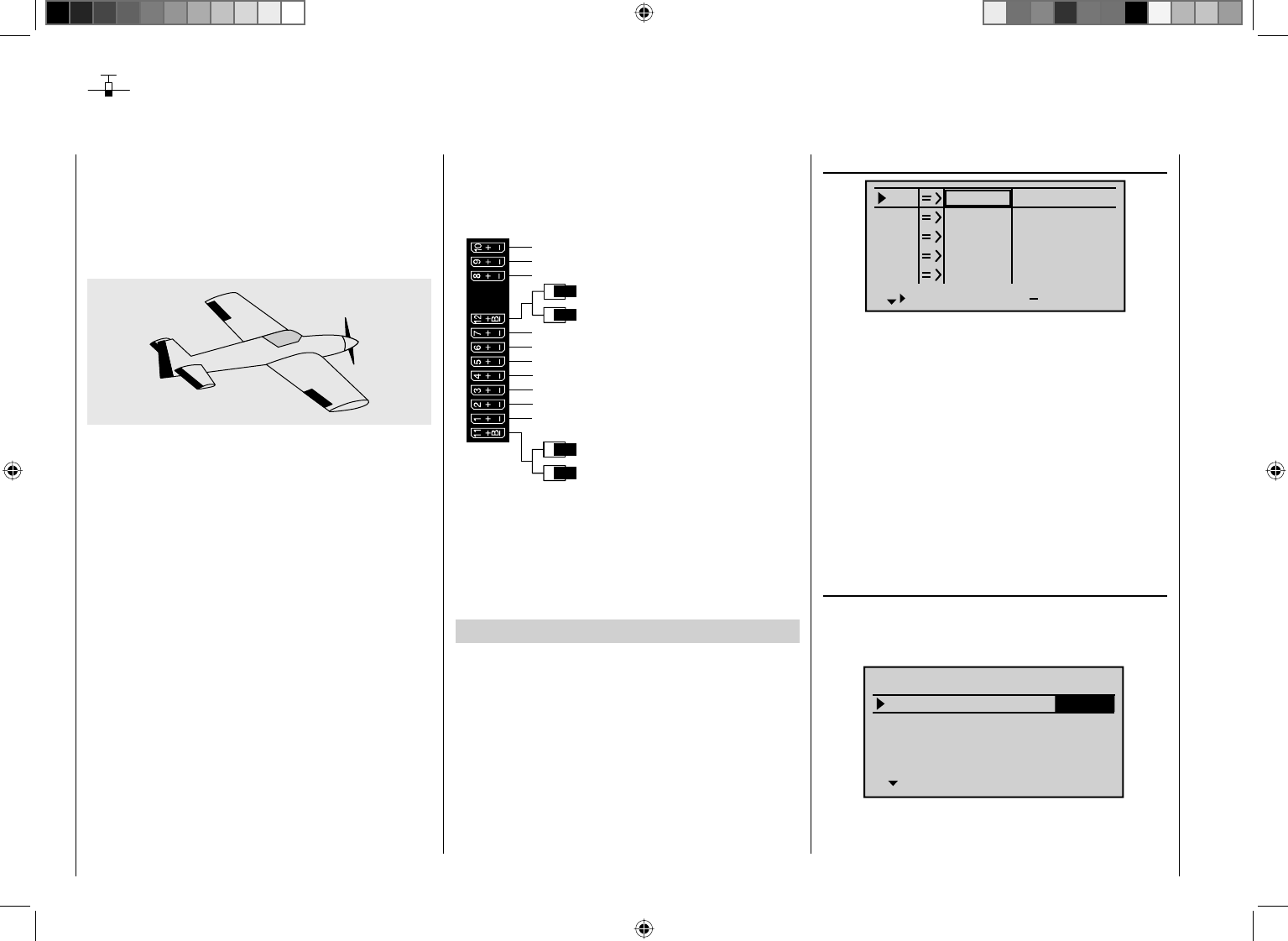
276 Detail program description - Control adjust
F3A model
F3A models are a part of the group of motor-driven
winged models. They are powered by a combustion or
electric motor. Models with electric motors can be used
in both the electric acrobatic class F5A and are also
competitive in the international model acrobatic class
F3A.
The basic comments and notices for the mechanical
installation of a remote steering system, which was
already referred to in the fi rst programming example on
page 236, also applies, of course, for F3A models and
does not need to be mentioned here again.
Faultlessly constructed F3A models exhibit a largely
neutral fl ying behavior. Ideally, they react with a good
nature but precisely to control movements without the
individual fl ight axes infl uencing one another.
F3A models are controlled with ailerons, elevator
and rudders. Normally, each aileron is actuated by a
separate servo. There is also the regulation of the drive
output of the motor (throttle function) and a retractable
landing gear in many cases. The assignment of the
channels 1 to 5, therefore, do not differ from the
previously described winged models.
The additional "Retractable landing gear" function is
to be provided on one of the auxiliary channels 6 to
9. It is best to actuate the landing gear with a switch
without center position. In addition, another mix offset
for the carburetor can – if necessary – be provided. You
normally use one of the two proportional rotary controls
on the transmitter, which actuates one of the unassigned
auxiliary channels.
Receiver power supply
Free or aux. function
Free or aux. function
Rudder
Aileron or left aileron
Elevator or 1st elevator
Free or 2nd elevator or aux. function
Receiver power supply
Airbrake or throttle servo
or speed controller (electric motor)
Right aileron
Free or aux. function (retracts)
Free or aux. function (mixture)
Free or aux. function
Free or aux. function
With the assignment of auxiliary channels at the
transmitter, we recommend making sure that the
operating elements required for this are easily
within reach, because during fl ight – especially in
competition – you have "very little time" to release the
joystick.
Programming
Since the basic programming of the transmitter was
already described in detail on pages 236 … 243, only
F3A-specifi c tips are added here.
In the menu …
"Servo adjustment" (page 90)
S1
S2
S3
Rev cent +
trv
0%
0%
0%
100% 100%
100% 100%
100% 100%
0%
0%
100% 100%
100% 100%
S4
S5
… the settings for the servos are carried out. Experience
has shown that working with at least 100 % servo
throw is benefi cial, because the control precision
is signifi cantly better if greater servo travel is used.
This should already be taken into account during the
construction of the model in the design of the rudder
linkages. Check the servo's direction of rotation. The
servo center should be adjusted mechanically, insofar as
possible.
Any corrections can be made on the software side in the
third column during the initial test fl ights.
Through the menu …
"Model type" (page 82 )
… the idle trim is activated for Channel 1 (normally
"rear", because full throttle is "front"). The trimming then
only works in the idle direction:
Tail type
Motor at C1
Normal
Aile/flaps 2AIL
M O D E L T Y P E
Brake Off In 1+100%
SEL
back
The remaining settings are made or left as shown in the
fi gure.

277
Detail program description - Control adjust
After test-fl ying and trimming of the model, we
recommend reducing the trim travel for the elevator and
ailerons The model has signifi cantly less of a reaction
to a movement of the trim lever. "Overtrimming" can
be avoided, because with full trim travel, under certain
circumstances, the movement by just one trimming
step can have too strong of an effect: Therefore, the
model which previously pulled slightly to the left, hangs
somewhat to the right after the trimming. For this
purpose, switch to the menu ...
"Joystick setting" (page 92)
… and reduce the number of trimming steps accordingly
in the "St" column:
Ch.1
Aile
Elev
Tr +
time
4
2
2
0.0s
0.0s
0.0s
0.0s
Rudd
0.0s
0.0s
0.0s
0.0s
GL
GL
GL
GL
St
2
It may also be necessary to assign a corresponding
operating element to a specifi c input for the activation
of the retractable landing gear and the mixer movement
through the menu …
"Control adjust" (page 96)
… such as one of the ON/OFF switches to the Input 6
for the landing gear and one of the proportional rotary
controls, e.g. CTRL 7, to the Input 7. However, since
it involves fl ight-phase independent settings, leave the
standard default "GL" in the "Type" column:
+33%
+33%
+33%
Ail
Ele
Rud
EXPO
–––
–––
SEL
normal
–––
(Some experts even use up to a +60 % exponential
degree.)
Since (some) combustion motors do not react linearly to
movements of the throttle joystick, through the menu …
"Channel 1 curve" (page 116)
… a "bowed" or, in other words, non-linear throttle
curve can be set. Four-cycle motors with Roots pumps,
in particular, such as OS Max FS 120, require a steep
ascension of the curve in the lower speed range.
However, the corresponding values must be adapted.
The C1 control curve for the motor could appear as
follows:
Input
Output
Point 1
–50%
0%
0%
C1
normal
Curve
Curve on
Only three interpolation points, "L" at -100 %, "H" at
+100 % and "1" at -50 % give the control travel the
rounded curve above.
Input 5
offset
0%
0%
0%
–––
0%
Input 6
Input 7
Input 8 –––
GL
GL
GL
GL
typ
Ct7
3
The control travel of the operating elements must be
adapted and can also be reversed with a negative travel
setting.
Notice:
A delay time for the extension and retraction can be
specifi ed for the retractable landing gear, which does not
work, however, for the landing gear servo C 713 MG,
Order No. 3887.
F3A models fl y comparatively fast and thus react
"harshly" to the control movements of the servos.
However, since small control movements and
corrections are not optically perceptible, because this
results in inevitable point deductions in competition, we
recommend setting an exponential control characteristic
of the joystick. For this purpose, switch to the menu …
" Dual Rate / Expo " (page 108)
Experience has shown positive results with values of
approx. + 30 % on the ailerons, elevator and rudders,
which you set in the right column with the arrow keys.
In order to be able to control the F3A model to run
smoothly and cleanly:
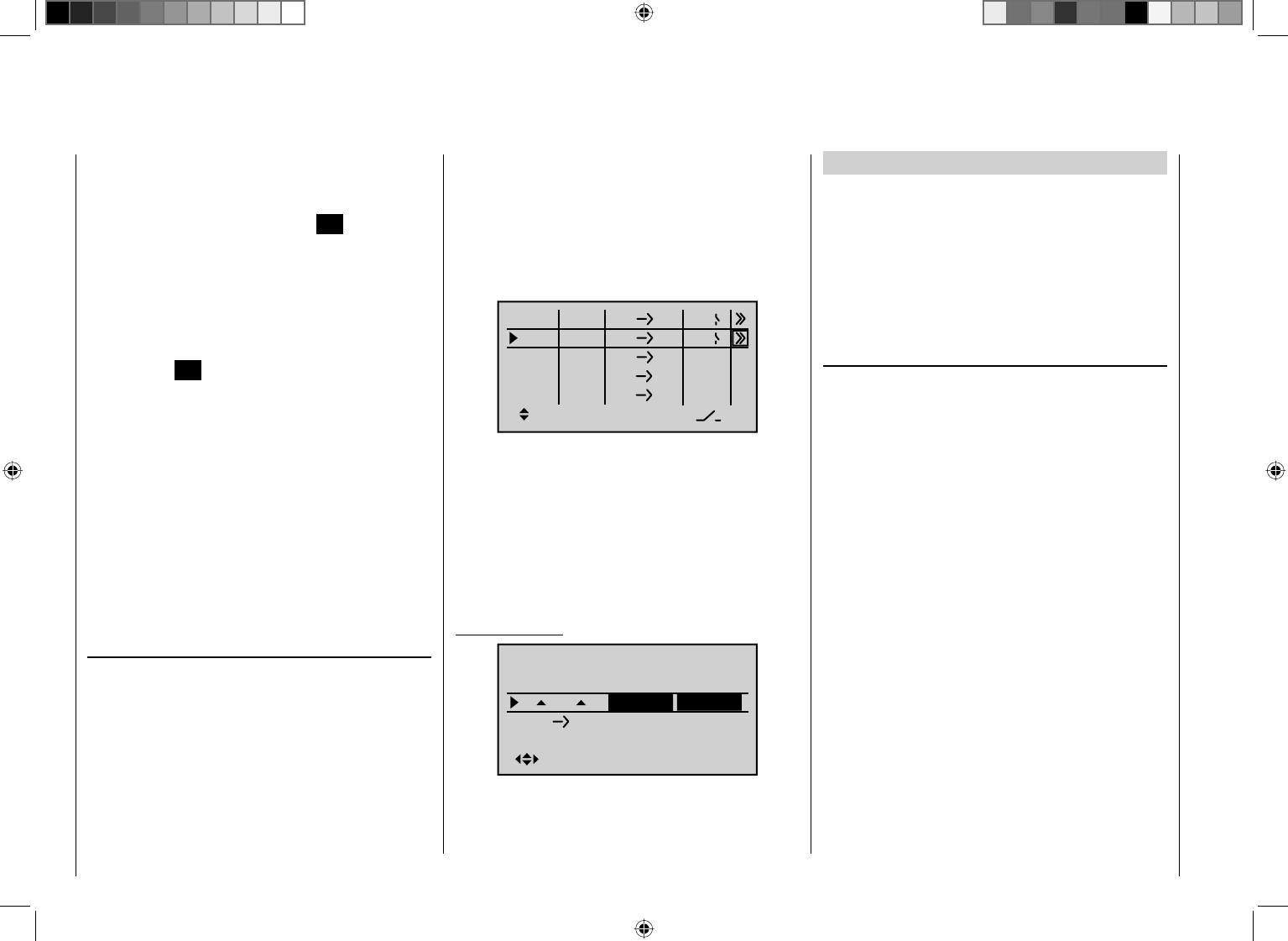
278 Detail program description - Control adjust
Basic procedure:
Move the C1 joystick and, along with it, the vertical •
line in the graphic display toward idle to -50 % control
travel and briefl y press the central SET key of the
right touch pad.
In order to attain the curve shape shown, raise •
this point with the arrow keys to approx. 0 % in the
inverse value fi eld of the "Point" line.
Then round the characteristic curve by moving the •
marking frame up to the "Curve" line, briefl y pressing
the central SET key of the right touch pad and then
changing the value from "Off" to "On" with the arrow
keys.
If additional interpolation points between the left ("L")
and right ("H") end are necessary, repeat Steps 2 and 3
analogously.
Since F3A models normally have two aileron servos,
experience has shown that it is benefi cial to move
both ailerons upward somewhat when landing. In the
process, the model usually fl ies somewhat slower and,
fi rst and foremost, more steadily for the landing. For this
reason, it is necessary to program mixers through the
menu ...
"Free mixers" (page 181)
... accordingly.
The ailerons are extended as landing assistance
depending on the position of the throttle stick, starting
from approximately half throttle toward idle. The
further the joystick is moved toward idle, the more the
ailerons defl ect upward. Just the opposite applies when
"throttling"; the ailerons are retracted again in order to
prevent a sudden rise of the model.
In order to prevent the model from climbing with the
aileron landing fl aps extended, the elevator must be
mixed in somewhat.
For this purpose, set the two linear mixers shown in
the following display. The activation of the mixers takes
place with one and the same switch, such as SW 8,
to which both mixers must be assigned with identical
switching direction.
ty fr to
M1
M2
M3
C1 5
C1 EL
M4
M5 ?? ??
?? ??
?? ??
8
8
Then switch to the second respective display screen in
order to adjust the respective mixing degrees. In both
cases the mixer neutral point is at the C1 control center.
Enter 0 % above the control center after selection of the
ASY fi eld for both mixers and below the control center
toward idle for:
MIX 1: -60 % ... -80 % and
MIX 2: -5 % ... -10 % .
Example L.MIX 1:
0%
0%0%
FLAP
normal
0%
0%
0%
FL
fl.pos
EL FL
Diff.
With this, the base setup model of an F3A model is
concluded.
Compensation of model-specifi c errors
Unfortunately, there are nearly always minor model-
specifi c "errors" through the mixers of a computer
remote control which must be compensated for.
However, before you begin with these settings, it should
be ensured that the model is faultlessly constructed,
optimally balanced over the longitudinal and transverse
axes and the down thrust and side thrust are correct.
Infl uence of longitudinal and transverse axes by the
rudder
The actuation of the rudder often infl uences the
behavior of the longitudinal and transverse axes. This
is particularly disruptive in so-called knife-edge fl ying,
in which the lift of the model with the rudder defl ected
should be created by the fuselage alone. In the process,
the model can rotate and change directions as though it
were controlled with the ailerons and elevator. Therefore,
a correction over the transverse axis (elevator) and/
or the longitudinal axis (ailerons) must be made, if
applicable.
This can also be carried out with the "Free mixers"
of mc-32 HoTT. If, for example, the model rotates
away to the right over the longitudinal axis with the
rudder extended in knife-edge fl ying, the aileron can be
defl ected to the left with the mixer. Changes in direction
over the transverse axis can be performed analogously
with a mixer on the elevator:
Correction over the transverse axis (elevator)•
L.Mix 3: "Rudd ¼ Elev"
Asymmetric setting. The appropriate values must be
tested in fl ight.
Correction over the longitudinal axis (aileron)•
L.Mix 4: "Rudd ¼ AIL"

279
Detail program description - Control adjust
Asymmetric setting. The appropriate values must be
tested in fl ight.
Relatively small mixer values are usually suffi cient
in this case, the range lies below 10 %, but can vary
from model to model. With the use of curve mixers, the
mix ratios can be adapted even more precisely to the
corresponding throw of the rudder. Again, no values are
indicated for this, because this would be model-specifi c.
Vertical ascent and descent
Some models have a tendency to deviate from the ideal
line in vertical ascents and descents.
In order to compensate for this, it is necessary to have a
center position of the elevator dependent on the throttle
joystick position. If, for example, the model begins to
hold off on its own in the vertical descent with a throttled
motor, some elevator must be mixed in at this throttle
position.
For this purpose, program a free mixer "C1 ¼ Elev".
The corresponding mixer values are normally under 5%
and must also be tested in fl ight.
Turning away over the longitudinal axis in idle
If the throttle is reduced, the model may begin to turn
away over the longitudinal axis in idle. This can be
counteracted with the aileron.
However, the more elegant solution is to correct this
effect with a free mixer "C1 ¼ Ail".
The input values here are usually very low (approx. 3 %)
and the settings should be made in calm weather. It
often suffi ces to only use the mixer between half throttle
and idle. Therefore program the mixer asymmetrically, if
applicable.
Turning away with the ailerons/landing fl aps
extended
If you move the ailerons upward for the landing, the
result is often a turning away over the longitudinal axis
due to various servo paths of the aileron servos or
due to design precisions. Therefore, the model begins
to automatically hang the left or right wing. This is
also easy to compensate for with a mixer "C1 ¼ AIL"
depending on the position of the ailerons/landing fl aps.
The mixer must be switched on and off with the same
switch with which you can switch the aileron/landing
fl ap function on and off (see previous page). Therefore,
it only works with the aileron/landing fl ap function
activated. The appropriate value must be tested in fl ight.
One additional comment regarding …
"FAIL-SAFE setting"
You utilize the safety potential of this option by the
safety potential by programming at least the motor
throttle position for combustion models to idle and the
motor function for electrically powered models to stop
for a Fail-Safe case. Then, in the event of a failure,
the model cannot become independent as easily and
cause property damage or even personal injury. If
you additionally program the fail-safe positions of the
rudders to that the model fl ies in gently sinking circles
in the event of a failure, there is a good chance that
the model even lands relatively gently on its own in the
event of a continuing connection failure. You also have
suffi cient time to re-establish the connection if the entire
2.4 GHz frequency band is temporarily disrupted.
In the receiver's condition as supplied, however, the
servos maintain their last validly recognized position
("hold") in the event of a fail-safe situation. As described
on page 196, you can defi ne a "Fail-safe position" for
each of the individual servo outputs of your receiver
(Fail-safe mode).
Summary
The settings described on this page are especially
useful for the "expert" who would like to have an entirely
neutral, precisely fl ying F3A model acrobatic model at
his or her disposal.
It should be mentioned this takes a lot of time, effort,
instinct and know-how. Experts even program during
the fl ight. To do this, however, is not suggested for an
advanced beginner who ventures into an F3A acrobatic
model. It would be best to turn to an experienced pilot
and carry out the settings step by step until the model
has the desired neutrality in its fl ight behavior. Then the
pilot can begin to learn the not always easy to perform
acrobatic fi gures with a model which fl ies faultlessly.
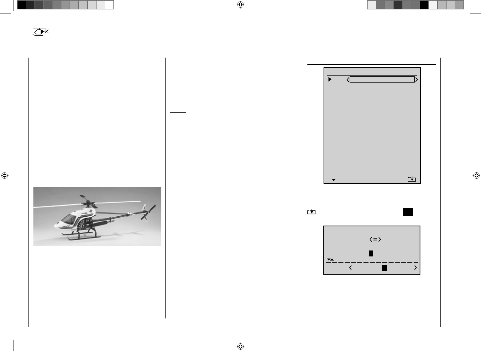
280 Detail program description - Control adjust
Helicopter models
With this programming example, you must have already
covered the description of the individual menus and
you must be familiar with the use of the transmitter.
In addition, the helicopter's mechanical construction
should correspond exactly to the corresponding manual.
The electronic capabilities of the transmitter should by
no means be used to straighten out rough mechanical
imprecision.
As the case often is in life, there are also various ways
and possibilities of achieving a specifi c goal with the
programming of the mc-32 HoTT. The following
example should provide you with a clearer structure for
logical programming. If there are multiple possibilities,
the simplest and most clearly arranged solutions are
recommended fi rst. In order for the helicopter to function
faultlessly later on, you are, of course, free to try out
other solutions which may be better for you.
The programming example is based on the clockwise-
rotating STARLET 50 helicopter from Graupner with
three pivot points each offset 120° of the swashplate
type "3sv(2 Roll)", beginner adjustment without
increased throttle curve; without heading-lock gyro
system and without transmitter-side gyro infl uence of the
"normal operating mode" and without speed regulator.
This simple program was also consciously selected to
demonstrate that a helicopter which fl ies really well can
also be attained with relatively little (programming) effort.
However, we do not want to dispense entirely with the
enhancement possibilities: Therefore, after the basic
description, you will fi nd adjustment information for the
gyro effect, the speed regulators and for the fl ight-phase
programming.
Notice:
If you are not interested in the combustion helicopter
described here, but a electric helicopter, please continue
reading anyhow! With the exception of the omitted idle
settings, you can practically adopt most of the settings
described in the following unchanged.
Some basic settings of the transmitter are necessary
with the initial commissioning. For this purpose, switch
to the menu …
"General settings (page 224)
Batterie type
Batterie warning
Touch Sense
Contrast
Ni-MH
Display light
Region
Voice volume
2
4.7V
0
Euro
3
unlim.
Beep volume 3
BASIC SETTINGS
Own
Stick mode 1
DSC Output PPM10
Pitch min back
Power-on beep yes
Power on warn. unlim
… and start with the entry of the "Owner name". Select
the characters for this from an extensive list on the
second display screen, which you can reach through the
symbol by briefl y pressing the central SET key of
the right touch pad:
!"#$%&’()+,–./012
3456789:;
Owner H-J Sandb
FGHIJKLMNOPQRSTUVWX
YZ[¥]^_`abcdefghijk
?@ABCDE
Select the default "Stick mode" according to the criteria
described on page 224.
The same applies for the default "DSC output".
The default "Pitch min" is based on your control habits.
With the creation of a new model memory you can
281
Detail program description - Control adjust
change these in the adopted defaults "Stick mode",
"DSC output" and "Pitch front/rear" as well as within
the respective model memory location.
The setting the "Contrast" line determines the legibility
of the display under poor light conditions and the setting
in the "Display light" line determines how long the
display lighting remains illuminated after the transmitter
is switched on or after the last key actuation.
With "Power-on beep yes/no" you determine whether
the transmitter plays a recognition melody when
switching on.
In the "Battery type" line you specify whether the
transmitter is supplied with current from a "NiMH" or a
"LiPo" battery, and in the "Battery warning" line below
it, you determine the voltage at which the low-voltage
warning of the transmitter should trigger. Do not enter a
value that is too low here, so you have enough time to
land your helicopter.
In the "Power-on warn." line you can adjust how long
the transmitter should wait after the last actuation of
an operating element until it alerts you that it is still
switched on with optical and acoustic warning signals.
With the values of the lines "Touch sense", "Voice
volume" and "Signal volume", you can adjust the
corresponding behavior of the transmitter to your
requirements. And, in the event that you (would like to)
commission your transmitter in France, the setting in the
"Region" line is important: The legal regulations of this
country require the selection of "France" instead of the
default setting "Euro".
If these settings are activated, it continues with the
menu ...
"Model select" (page 63)
Select a free storage location with the arrow keys ...
03
04
05
¿¿¿ free¿¿¿
02
01
06
R12
¿¿¿ free¿¿¿
¿¿¿ free¿¿¿
¿¿¿ free¿¿¿
¿¿¿ free ¿¿¿
…and open this by briefl y pressing the central SET
key of the right touch pad. In the subsequently opening
display, with the key f of the left or right touch pad,
select…
Select model typ
… the "Heli" model type. The display immediately
switches to the base screen if you confi rm this selection
by briefl y pressing the central SET key of the right touch
pad.
Notice:
If the "Select model type" option has been opened, •
the process cannot be canceled. Even if you switch
off the transmitter, this selection must be made! In
any case, you can undo this by subsequently deleting
the respective model memory.
If the "Throttle too high" warning appears, this can •
be deleted by turning the proportional rotary control
CTRL 6 counterclockwise until its limit.
If battery voltage is too low, the model switchover •
cannot be made due to reasons of safety. An
appropriate message will appear in the screen:
not possible now
voltage too low
Once this fi rst hurdle is cleared, the connection of the
receiver built into the model at this model memory must
be made in the menu …
"Base setup model" (page 74 … 80)
. For this purpose, switch to the line "RF bind":
1
n/a
n/a
BD1
Starlet
BD2
E12
Mod.name
Stick mode
RF BIND
BASIC SETTINGS, MODEL
RF transmit OFF
Notice:
After confi rmation of the model selection in the base
screen, if you confi rm the message appearing in the
screen for a few seconds …
BIND N/A
OK
… by pressing the SET key of the right touch pad, you
automatically come to this line.
In the line"RF Bind." you delete the connection process
between model memory and receiver, as described in
detail on page 74. Otherwise, you cannot address the
receiver.
Afterwards, using the arrow keys of the c
left or right
four-way pad, move up to the fi rst line and begin with
the actual model programming in the "Mod. Name" line:
Now enter an appropriate name for the model memory,
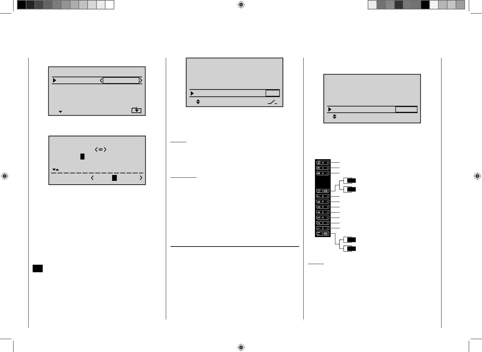
282 Detail program description - Control adjust
99sec
PPM10
8I
ON
DSC Output
Autorotation
RF transmit
BASIC SETTINGS, MODEL
RF Range Test
The selected switch should be in a location on the
transmitter which is easily within reach – without
releasing a joystick – e. g. above the pitch joystick.
Notice:
More more information about the setting of this
"emergency shutoff", see the beginning of the second
following double-page.
Another tip:
Make a habit of giving all switches a common switch-on
direction; then a quick glance over the transmitter prior
to the fl ight should suffi ce – all switches off.
The possible settings of the lines "Automatic C1
position" and "Motor stop" are not of interest at fi rst.
Additional settings specifi c to helicopters are made in
the menu …
"Helicopter type" (page 86)
Under "Swashplate type", select the control of the
swashplate and/or the pitch function. In this example:
"3Sv(2rol)".
The lineLinear swashpl." is not of interest at fi rst.
In the line "Rotor direct" you defi ne whether the
rotor - as viewed from above - rotates to the right or left.
In other words, whether it rotates counterclockwise or
clockwise. In this example "right".
With the default "Pitch min" adopted from the "General
…
1
n/a
bind
BD2
BD1
n/a
R12
Mod.name
Stick mode
RF BIND
BASIC SETTINGS, MODEL
Rcv Ch Map
… which is comprised of the characters available for
selection on the second screen of the "Mod. Name" line:
!"#$%&’()+,–./012
3456789:;
Mod Name STARL
FGHIJKLMNOPQRSTUVWX
YZ[¥]^_`abcdefghijk
?@ABCDE
After entering the "Model name" the specifi cations for
the "Stick mode" and "DSC output" adopted from the
"General settings" are checked again, for which you
can change the storage location, if applicable.
An additional option is activated in the line
"Autorotation". Even if you are not an advanced pilot,
the autorotation switch should at least be set an an
emergency shutoff switch for the motor.
For this purpose, select the line "Autorotation", activate
the switch assignment by briefl y pressing the central
SET key of the right touch pad and move one of the two-
stage switches, e. g. SW 8, to the ON position:
settings", it is checked whether the entry "front" or "back"
corresponds to your habits and changed, if applicable:
3Sv(2rol)
SEL
Linear. swashpl.
Swashplate
no
Rotor direct right
HELI TYPE
Pitch min. back
"Expo thro lim." in the bottom line of this display is not
of interest yet.
By now, the servos should be plugged into the receiver
in the intended sequence:
Receiver power supply
Free or aux. function
Free or aux. function
Tail rotor servo (gyro system)
Roll 1 servo
Pitch-axis 1 servo
Free or speed governor or aux. function
Receiver power supply
Collective pitch or roll 2 or
Pitch-axis 2 servo
Free or aux. function
Throttle servo or speed controller
Gyro gain
Free or aux. function
Free or aux. function
Notice:
Please note that with the newer Graupner mc and
mx remote control systems the fi rst pitch servo and
the throttle servo are reversed when compared with the
older systems.
The degrees of mixing and mixing directions of the
swashplate servos for pitch, roll and nick are already
preadjusted to +61 % in the menu ...
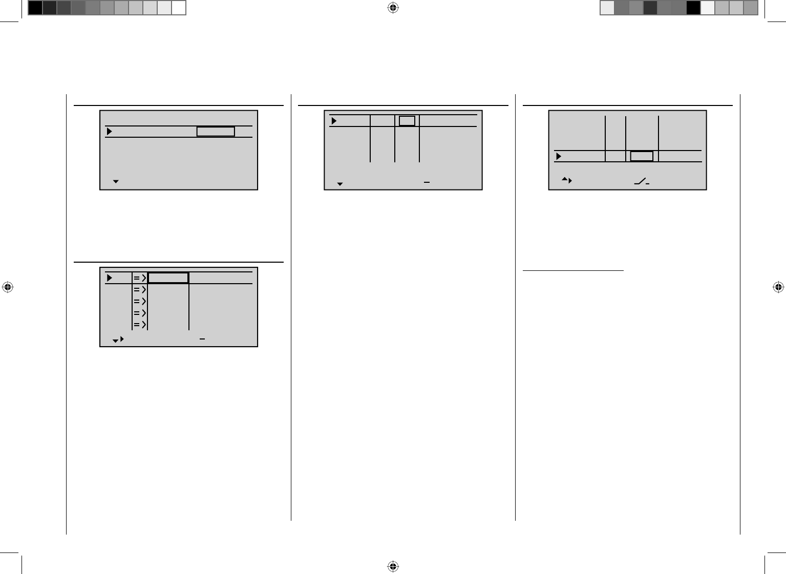
283
Detail program description - Control adjust
"Swashplate mixer" (page 196)
SWASH MIXER
Pitch
Roll
Nick
+61%
+61%
+61%
SEL
... If the swashplate mixer should not follow the joystick
movements properly, fi rst change the mixing directions
from "+" to "-" before you change the servo directions in
the menu ...
"Servo adjustment" (page 90)
S1
S2
S3
Rev cent +
trv
0%
0%
0%
100% 100%
100% 100%
100% 100%
0%
0%
100% 100%
100% 100%
S4
S5
... In this menu you can also adjust the travel and the
directions of the individual servos. As a basic rule you
should strive to maintain the servo travel 100 % in order
to attain the best resolution and positioning precision.
The direction of travel is determined with "Rev." and,
in the process, make sure that the direction is correct.
The tail rotor servo must run so that the nose (!) of the
helicopter follows the tail joystick direction.
In the menu …
"Joystick setting" (page 94)
Thr.
Roll
Nick
Tr +
time
4
4
4
0.0s
0.0s
0.0s
40.0s
Tail
0.0s
0.0s
0.0s
0.0s
TL
GL
GL
GL
St
… adjust the incremental width for each "click" of the
digital trim keys in the "St" column.
The C1 trimming only affects the throttle servo for the
helicopter. At this point there is no need to go into the
particulars of this trimming ("cut-off trim") once again.
For this purpose, please refer to page 54. (Thanks to the
digital trimming, trim values can be automatically saved
with a model changeover and with the mc-32 HoTT
and even with a change of the fl ight phase).
An additional setting which is specifi c to helicopters can
also be made in this menu in which you determine which
function the trim slider on the pitch joystick should have.
For this purpose, the setting "TL" is selected or left in
the "Throttle" line. In doing so, the trim lever corresponds
to the accustomed idle trim. If you "slide" it all the way
to the front, the throttle limiter seamlessly adopts the
throttle release later, which is assigned to "Th.L.12" in
the ...
""Control adjust" menu (page 100 … 107)
Input 9
offset
0%
0%
0%
–––
0%
Input
Input
Th.L.12 Ct6
–––
–––
GL
GL
GL
GL
typ
normal
10
11
… whereas "free" is specifi ed for all other inputs.
This input, "Th.L.12" serves as the throttle limiter. It
only has an effect on output "6", where the throttle servo
is located. The left proportional rotary control CTRL 6 is
assigned to the throttle limiter by default.
Once again, as a reminder:
W
• ith the user of the "throttle limiter" function, you
do not have to program a fl ight phase "throttle
preselection".
The throttle limiter does not control the throttle servo; •
it only limits the travel of the throttle servo in the full
throttle direction according to its position. In general,
the throttle servo is controlled through the throttle
curve(s) set in the "Helicopter mix", which is why
Input 6 must be left "free". In the respect, refer also
to the pages 168 to 170 of the manual.
The C1 trimming also affects only the throttle servo •
for the helicopter. At this point there is no need
to go into the particulars of this trimming ("cut-off
trim") once again. For this purpose, please refer to
page 54. (Thanks to the digital trimming, trim can be
automatically saved values with a model changeover
as well as with a change of the fl ight phase).
A detailed description of the idle run base setup •
model and the adjustment of idle and throttle limit
can be found beginning on page 104.
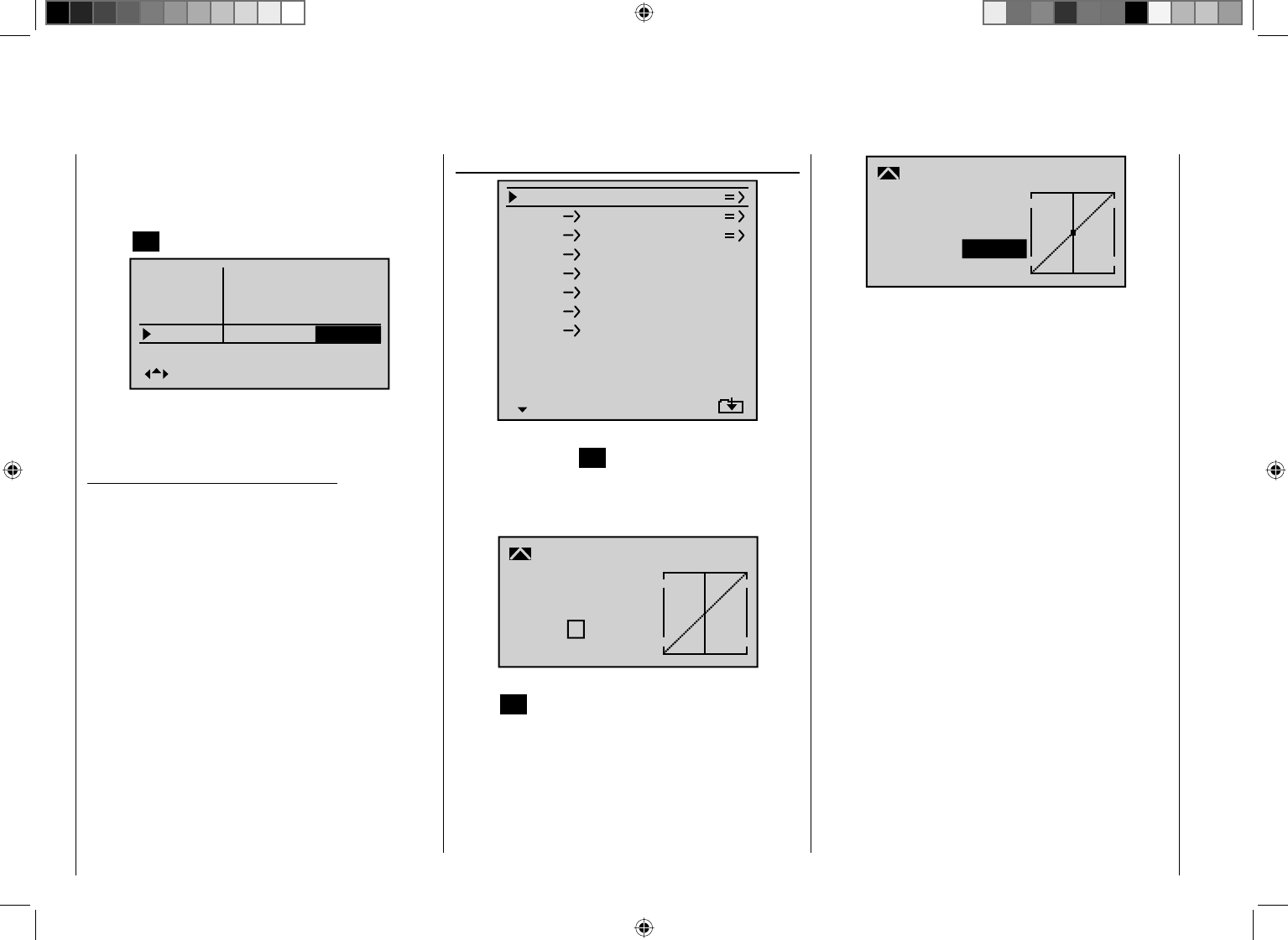
284 Detail program description - Control adjust
Then switch to the "Travel" column with the arrow keys
f of the left or right touch pad and increase the now
inversely highlighted value from +100 % to +125 % with
a fully opened throttle limiter after briefl y pressing the
central SET key of the right touch pad:
– travel +
+100%
+100%
+100%
+100%
+100%
+100%
+100%
normal
Input 9
Input10
Input
Th.L.12 +125%
11
In doing so, it is assured that the throttle limiter releases
the entire throttle travel with the pitch joystick later
during fl ight.
Adjustment notice for electric helicopters:
Since electric drives do not, by nature, require an idle
setting, in the scope of the base setup of an electrically
driven helicopter it must only be ensured that the
regulating range of the throttle limiter safely exceeds
and undercuts the normally reached adjustment range
of the motor control of -100% to +100 %. If necessary,
therefore, the adjustment of the "travel" setting of
the throttle limiter described above must be modifi ed
accordingly, for example, to symmetric 110 %. The
further adjustment, however, can take place analogously
to the combustion helicopter described here.
With this process, you have not carried out the basic
settings for the transmitter as they are needed again
later for further model programming.
The actual helicopter-specifi c settings take place
primarily in the menu …
""Helicopter mix" (page 164 … 179)
C1
C1
Pitch
Throttle
Tail
Tail 0%
Roll 0%
Throttle
Roll
Throttle
Tail
Nick
Nick
Throttle
Tail
Swash rotation
Swash limiter
0%
0%
0%
0°
OFF
Normal
Gyro suppress 0%
The "Pitch" function appears right in the fi rst line. By
pressing the central SET key of the right touch pad,
you switch to the corresponding submenu. The graphic
representation of the pitch curve appears here; it is
initially only defi
ned by the points "L" and "H":
Input
Output
Point ?
0%
0%
0%
Pitch
normal
Curve off
Now place point "1" in the center by briefl y pressing the
central SET key of the right touch pad:
Input
Output
Point 1
0%
0%
Pitch
normal
Curve off
0%
Always try to make due with these three points initially;
more points can "over-complicate" the matter and are
more of a burden at this point.
The reference point for the hovering should generally
be the mechanical center position of the pitch joystick,
because this position comes closest to the normal
control feel. Although the curve adjustment enables
other settings, you must know exactly what you
are doing. First set the pitch joystick in the center.
The servos which you had previously set according
to manufacturer specifi cations have their levers at
positioned perpendicularly to the servo housing
(normally). The hovering pitch value of 4 ° to 5 ° is now
mechanically set at the control levers for the blades. In
principle, all known helicopters fl y with this setting.
Then move the pitch joystick towards maximum pitch
until the limit position. (The vertical line shows you the
current joystick position.) Now change point "H" of the
pitch curve with the arrow keys of the right touch pad so
that the pitch maximum is approximately 9 ° at the rotor
blades of the main rotor. With a value of approximately
+50 % this may be the case:
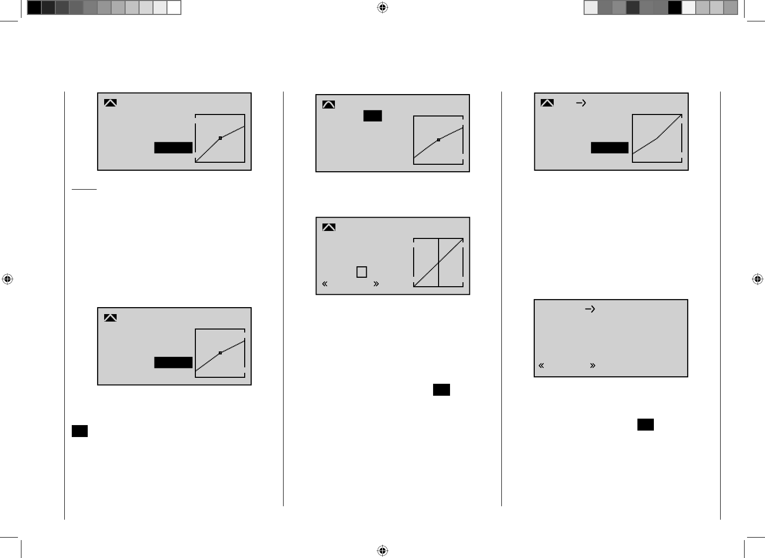
285
Detail program description - Control adjust
H
+100%
+50%
Pitch
normal
+50%
Input
Output
Point
Curve off
Notice:
A rotor adjustment gauge, such as the Graupner
adjustment gauge, Order No. 61 is very useful in reading
the angle.
Now move the pitch joystick toward the pitch minimum
position until its limit position. Depending on the ability
of the pilot, adjust the value of point "L" so that the blade
angle of approach is 0 to -4 °. Now a slightly pitched line
arises at the hovering points, the so-called pitch curve,
which can appear as follows:
L
–100%
–75%
Pitch
normal
–75%
Input
Output
Point
Curve off
Now you can, if you like, move the marking frame
upward with the arrow keys to the "Curve" line and after
activation of the value fi eld by briefl y pressing the central
SET key of the right touch pad, set the curve function of
the mixer to "on".
L
–100%
–75%
Pitch
normal
–75%
on
Input
Output
Point
Curve
If you now switch to autorotation phase – at the bottom
left of the display the fl ight phase name "Autorot"
appears – the "old" pitch curve is again:
?
0%
0%
0%
Pitch
Autorot
Input
Output
Point
Curve off
Now carry out the same setting as before in the normal
phase. Only at point "H" – at pitch maximum – the pitch
angle can be increased by approximately 2 °. In doing
so, you will have somewhat more of an angle to catch
the model later on (1).
After setting the pitch curve, move the autorotation
switch back and return to the helicopter mixer menu
selection by briefl y pressing the central ESC key of the
left touch pad. From there, switch to the line
"C1 ¼Thro" in order to adjust the throttle curve.
First the adjustment range of the idle trim must be
adjusted with the throttle curve. For this purpose, move
the pitch joystick to its minimum position and then set
point "L' to approximately -65 %.
–100%
–65%
C1 Throttle
normal
L–65%
Input
Output
Point
Curve off
With the throttle limiter closed and the idle trim
completely open, move the pitch joystick back and forth
somewhat at the minimum limit position. The throttle
servo may not move with it in the process. No you have
established a seamless transition from the idle trim to
the throttle curve. The further settings along the throttle
curve must be carried out later in fl ight.
If you switch from this graphic to the autorotation phase
for testing purposes, the following appears instead of the
accustomed representation:
OFF
C1 Throttle
Autorot
That means that this mixer is switched off and the
throttle servo is switched to a fi xed value, which can be
adjusted as follows:
Return to the menu list by pressing ESC. As long as you
are still in the autorotation phase, new submenus are
listed; specifi cally:
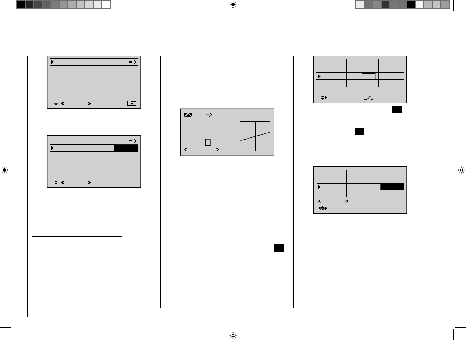
286 Detail program description - Control adjust
Pitch
Thr setting AR
Tailoffset AR
Gyro suppress 0%
Swash rotation 0°
OFF
Autorot
–90%
0%
Swash limiter
The line "Thr. setting AR" is important. Enter the value
to the right depending on the servo direction to either
approximately +125 % or -125 %.
0%
0°
Autorot
0%
SEL
–125%
Pitch
Thr setting AR
Tailoffset AR
Gyro suppress
Swash rotation
OFFSwash limiter
In doing so, the motor is safely switched off in the
autorotation phase (in case of emergency). Later, when
you have gained enough experience to practice the
autorotation fl ight, a more stable idle can be entered
here.
Adjustment notice for electric helicopters:
Since the motor must also be shut off for electrically
powered helicopters in case of an emergency, this
setting is adopted without change.
The further submenus are not important at the moment.
By switching off "autorotation", it returns to the fi rst
menu list.
Select the setting screen of "C1 ¼ Tail" in order to
adjust the static torque balance at the tail rotor. In this
case, also work with a maximum of three interpolation
points; everything else is reserved for the experienced
pilot. For this purpose, change the presetting intended
for heading lock systems from a uniform 0 % at point
"L" (pitch minimum) to -30 % and at the opposite end, at
point "H" to +30 % (pitch maximum). These values may
have to be corrected in fl ight. If applicable, you must also
set point "1" in the center when doing so:
0%
0%
0%
Tail
C1
Input
Output
Point
Normal
Curve off
?
Now, for testing purposes, switch back to the
autorotation phase. Here the setting is also deactivated;
the tail servo no longer reacts to pitch movements
(no torque usually arises when the main rotor is not
powered). All additional interpolation points are not
currently of importance yet.
If, contrary to the specifi cation, the gyro has a
transmitter-side sensitivity setting, you still need a free
proportional control, e.g. CTRL 7. In the menu …
"Control adjust" (page 100 … 107)
… you can assign this to the "Gyr" input. Activate the
control assignment by briefl y pressing the central SET
key of the right touch pad and then turning the rotary
control until its control number appears in the display:
Input 5
offset
0%
0%
0%
–––
0%
Throt
Gyro
Input 8 –––
–––
GL
GL
GL
GL
typ
normal
6
7Ct7
Conclude this entry by briefl y pressing the ESC key of
the left touch pad and then switch with the arrow key f
of the left or right touch pad to the "- Travel +" column.
After pressing the central SET key of the right touch
pad, the maximum sensitivity of the gyro, e. g. 50 %, can
now be set in the inverse value fi eld. For this purpose,
rotate the selected control to the corresponding screen
so that only one value fi eld is represented inversely:
– travel +
+100%
+100%
+100%
+100%
+100%
+100%
+100%
Normal
Input 5
Throt
Gyro
Input 8
6
7+50%
Now you have a fi xed value as long as the rotary control
is at the right limit position. The correct value must be
adjusted in fl ight.
In the process, however, always observe the
adjustment instructions accompanying your gyro
sensor, because your helicopter will not be able to
fl y otherwise!
To conclude this initial programming, a few words should
be mentioned about the menu …
287
Detail program description - Control adjust
"Channel 1 curve" (page 119)
Input
Output
Point ?
0%
0%
0%
C1
normal
Curve
Curve off
This function is a type of "convenient exponential curve"
for the throttle/pitch joystick and the mixer functions
connected to it.
If ever, this curve should only be applied "cautiously" at
the very end, when all adjustments have been made. It
should never be used for the throttle/pitch adjustment!
The overlappings result in "nasty" effects.
With this, all helicopter-specifi c settings which can
be made on the "workbench" are now completed.
The further fi ne-tuning must take place in fl ight. The
fl ight-tested, (hopefully) minor (digital) trim settings are
automatically saved.
Larger deviations should fi rst be mechanically adjusted
or adjusted according to the previously discussed
settings.
Further settings
Following this programming example, you have provided
a helicopter with a basic adjustment for the hovering
training and simple trips. Depending on your knowledge
and experience as a pilot, additional functions can, of
course, also be activated.
If you want to fl y at different speeds and with different
trimming, you activate the so-called "fl ight phases",
which can be called with assigned switches as an
alternative to the previously described "normal phase".
For this purpose, fi rst open the menu …
"Phase setting" (page 132)
… whereby the symbols appearing in the second
column after the switch assignment in the "Phase
assignment" menu have the following meanings:
"–": No phase switch available
"+": Phase switch available
"¾": Currently active phase
Pha1
Pha2
Pha3
Name ph.Tim.
Pha4
Autorot
–
–
–
+
Auto
¾
However, you should consider beforehand whether you
want to activate the up to six additional fl ight phases
with single switches or, more logically, with three-stage
switches in addition to the autorotation phase. The latter
possibility is more logical and usually more clearly laid
out.
In the upper fi gure the line "Autorot" is already selected.
When activated, the autorotation phase always has
precedence over any other phases you assign switches to.
However, in the "Name" column you fi rst assign
"meaningful" names to Phases 1 to 3, which are
adopted from a list. These identifi cations serve for the
better differentiation and are shown later in the base
screen and for all fl ight-phase dependent menus, for
example:
Pha1
Pha2
Pha3
Name ph.Tim.
Pha4
¾
+
+
Normal
Hover
–
–
0.1s
0.1s
0.1s
0.1s
0.1s
Speed
AutorotAuto
Then, in the fourth column, enter the switching time
with which the FROM phase should switch TO the next
respective phase. Approximately 1 s should suffi ce:
Pha1
Pha2
Pha3
Name Sw.time
Pha4
¾
+
+
Normal
Hover
–
–
1.1s
1.1s
5.0s
0.1s
Speed
AutorotAuto
1.1s
This value can also be adjusted later according to your
personal preferences. Please observe in the process
that TO the autorotation phase, whose name is defi ned
as "Autorot", is switched without a time delay. If
necessary, enter the time with which a change FROM
the autorotation phase to a different phase should be
affected.
In order to be able to switch between the individual fl ight
phases, the assignment of the individual switches or the
three-stage switch is necessary.
288 Detail program description - Control adjust
The assignment of the switch takes place in the menu …
"Phase assignment" (page 134)
Under "C" and "D" assign the three-stage switches SW
4 + 5, for example:
PHASE ASSIGNMENT
A B C D E F
1 Normal
245
prior
combi
Now you must assign the corresponding fl ight phase
from the "Phase setting" menu to the respective switch
position. Since you have already assigned names, the
name of the phase "1 Normal" appears to the right in the
display. If the already assigned autorotation switch was
activated, the following warning message appears in the
display:
PHASE ASSIGNMENT
A B C D E F
1 Normal
245
prior
combi
Autorot
As a reminder:
The autorotation phase has absolute precedence.
Therefore, move the autorotation switch back and then
move the selected switch, in our example the three-
stage switch SW 4 + 5, to the one limit position. Then
switch to the bottom right with the arrow keys and
activate this input fi eld:
A B C D E F
245
1 Normal
PHASE ASSIGNMENT
prior
combi
Now select the desired fl ight phase for this switch
position - for example, "2 Hover" ...
A B C D E F
245
2 Hover
PHASE ASSIGNMENT
prior
combi
… and confi rm this selection by briefl y pressing the
central SET key of the right touch pad or move the
switch to the other limit position and defi ne the name for
this switch position, such as "3 Speed".
A B C D E F
245
3 Speed
PHASE ASSIGNMENT
prior
combi
The switch center then receives the name "1 Normal" as
shown above to the left.
Notice:
Exchanged or different name assignments for the
three switch positions are, of course, also possible.
For example, with the use of one of the rotational speed
controllers programmed according to the description
in the next column, a sequences like "normal / hover /
acro" would be logical.
The model settings made before the assignment of a
phase switch are now in the fl ight phase "Normal". This
is the phase which is called after the above defi nition in
the switch center position.
This normal setting, which was already tested in fl ight,
can be copied to a different fl ight phase so that fl ying
can take place in the same manner in every phase at
fi rst. For this purpose, use the menu ...
"Copy / Erase" (page 64)
=>
=>
=>
=>
=>
=>
=>
Copy flight phase
Erase model
Copy model–>model
Export to SD
Import from SD
With the operation of the fl ight phases, it is possible
to carry out changes in the phase-dependent menu
for each individual phase. Since the mc-32 HoTT
has digital trimming, in addition to the fl ight-phase
dependent menu settings in the helicopter program,
the trim positions of roll, nick and tail rotor joystick are
also saved depending on the fl ight phase, see menu
"Joystick setting" page 94:
Thr.
Roll
Nick
Tr +
time
4
4
4
0.0s
0.0s
0.0s
40.0s
Tail
0.0s
0.0s
0.0s
0.0s
TL
GL
GL
GL
St
289
Detail program description - Control adjust
Enhancement recommendation:
Rotational speed regulator
At some point in time you may want to install a
rotational speed regulator in the helicopter, such as
mc-Heli-Control, in order to be able to fl y with speeds
automatically kept at a constant. In the process, it is
logical to couple the individual rotational speeds with the
fl ight phases so that further additional adjustments are
possible.
It is mandatory for the transmitter-side programming
that the rotational speed regulator was installed
and programmed according to the manufacturer's
instructions. Of course, the mc-32 HoTT also enables
further possibilities for the realization of different speeds
in the individual phases. For a practical recommendation
with maintenance of the throttle limiter function, see the
description beginning on page 169.
If you have adjusted your helicopter according to
this programming principle, it is not yet a competition
helicopter, but it already permits sophisticated fl ying.
You should only activate additional functions if the model
fl ies faultlessly so that the (desired) improvements
are also easy to follow. Insofar as possible, activate
individual functions on an individual basis so that you
can actually recognize and attribute the change. Bear
in mind that it is not the quantity of functions used that
distinguishes good pilots, but what they can do in terms
of fl ying with relatively little.
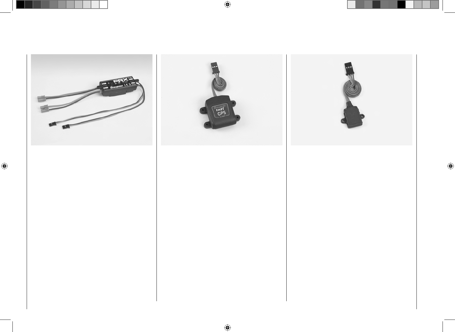
290 Appendix
Vario moduleGraupner HoTT
Order No. 33601
Vario with altitude signals and 5 ascend and descend signal tones
each, altitude display and memory of the min. and max. altitude
Additional warning thresholds for min. altitude, max. altitude, rate of •
ascend and descend in two stages
Adjustable warning time: OFF, 5, 10, 15, 20, 25, 30 seconds, always•
Adjustable warning repetition time: Always, 1, 2, 3, 4, 5 min, once•
The Vario sensor can be connected directly at the telemetry input of •
the receiver.
Technical data
Altitude measurement: -500 m … +3000 m•
Resolution: 0.1 m•
Vario sensitivity: 0.5 m/3s, 1 m/3 s, 0.5 m/s, 1 m/1 s, 3 m/s •
programmable by tone
Average calculation: 4 - 20 measurements programmable per •
measurement value
PRX (Power for Receiver)
Order No. 4136
Highly developed, stabilized receiver current supply with intelligent
power management.
The unit ensures a stabilized and adjustable current supply of the
receiver in order to increase the reliability of the current supply even
further. Suitable for various receiver batteries in order to guarantee
an uncomplicated and wide range of application. Even if the battery
voltage is only interrupted for a short time, this is recorded and
displayed in order to counteract an under-dimensioning or even the
failure of the receiver battery with this notice.
• For the operation of one or two receiver batteries.
(Simultaneous discharge with the operation of two batteries)
• Suitable for fi ve or six-cell NiMH or two -cell LiPo or LiFe batteries.
Graupner/JR, G3.5, G2 and BEC plug systems.
• Three adjustable levels for the output voltage for the supply of the
receiver (5.1V / 5.5V / 5.9V).
• Two ultra-bright LEDs show the operating statuses of Battery 1 and
Battery 2 separately.
• Integrated high-quality On/Off switch
• High-current resistant design
• Flatter design of the switch and the LEDS in order to not infl uence
the appearance and characteristics of the model.
• Linear layout of fastening lugs, LEDs and switches for a simple
installation using an accompanying hole template.
GPS/Vario module Graupner HoTT
Order No. 33600
Vario with altitude signals and and fi ve ascend and descend signal
tones as well as integrated GPS with range fi nding, distance
measurement, display of the fl ight direction and the coordinates
Additional warning thresholds for min. altitude, max. altitude, rate of •
ascend and descend in two stages
Altitude display and memory of the min. and max. altitude.•
Adjustable warning time: OFF, 5, 10, 15, 20, 25, 30 seconds, always•
Adjustable warning repetition time: Always, 1, 2, 3, 4, 5 min, once•
The GPS/Vario sensor can be connected directly at the telemetry •
input of the receiver.
Vario technical data:
Altitude measurement: -500 m … +3000 m•
Resolution: 0.1 m•
Vario sensitivity: 0.5 m/3s, 1 m/3 s, 0.5 m/s, 1 m/1 s, 3 m/s •
programmable by tone
Average calculation: 4 - 20 measurements programmable per •
measurement value
Appendix
291
Appendix
General Engine-Module Graupner HoTT
Order No. 33610
General sensor for Graupner HoTT receivers and models with
combustion or electric motor:
2x temperature and voltage measurements with warning thresholds •
for min. and max. voltage and min. and max. temperature
Single cell measurement with warning thresholds for min. voltage•
Voltage, current and capacity measurement with warning thresholds •
for min. and max. voltage, max. capacity and max. current
Programmable current limiting•
Current limiting with shunt resistors 2 x 1 mOhm parallel = 0.5 mOhm•
Rotational speed measurement and warning thresholds for min. and •
max. rotational speed
Fuel measurement with warning thresholds in 25 % increments •
(after software update).
Adjustable warning time: OFF, 5, 10, 15, 20, 25, 30 seconds, always•
Adjustable warning repetition time: Always, 1, 2, 3, 4, 5 min, once•
2x temperature selectively 0 to 120 °C or 200 °C and voltage •
measurement up to 80 V DC
1x rotational speed measurement up to 100,000 rpm with a two-•
blade propeller
1x speed controller/servo input, 1x rotational speed regulatio•
n input, 1x speed controller/servo output for rotational speed
regulation
1x current, voltage and capacity measurement up to 40 A (pulse 1 s •
up to 60 A) and up to 30 V
1x single cell monitoring for 2 - 6S lithium batteries (LiPo, LiIo, LiFe) •
etc.; see www.graupner.de for the respective product•
General Air-Module Graupner HoTT
Order No. 33611
General sensor for Graupner HoTT receivers and models with
combustion or electric motor:
Vario with altitude signals and ascend and descend signals and •
additional warning thresholds for min. altitude, max. altitude, rate of
ascend and descend in two stages
Altitude display (-500 … +3000 m) and memory of the min. and max. •
altitude.
2x temperature and voltage measurements with warning thresholds •
for min. and max. voltage and min. and max. temperature
Single cell measurement with warning thresholds for min. voltage•
Voltage, current and capacity measurement with warning thresholds •
for min. and max. voltage, max. capacity and max. current
Rotational speed measurement with rotational speed regulation •
(programmable) and warning thresholds for min. and max. rotational
speed
Fuel measurement with warning thresholds in 25 % increments.•
Adjustable warning time: OFF, 5, 10, 15, 20, 25, 30 seconds, always•
Adjustable warning repetition time: Always, 1, 2, 3, 4, 5 min, once•
2x temperature selectively 0 to 120 °C or 200 °C and voltage •
measurement up to 80 V DC
1x rotational speed measurement up to 100,000 rpm with a two-•
blade propeller
1x speed controller/servo input, 1x rotational speed regulation input, •
1x speed controller/servo output for rotational speed regulation
1x current and voltage and capacity measurement up to 40 A (pulse •
1s: 60 A ) and up to 30 V
etc.; see www.graupner.de for the respective product•
Electric Air-Module Graupner HoTT
Order No. 33620
General sensor for Graupner HoTT receiver and models with electric
motor
Vario with altitude signals, ascend and descend signals as well as •
additional warning thresholds for min. altitude, max. altitude, rate of
ascend and descend in two stages
Altitude display (-500 … +3000 m) and memory of the min. and max. •
altitude.
2x temperature and voltage measurements with warning thresholds •
for min. and max. voltage and min. and max. temperature
Single cell measurement 2 ... 14S with warning thresholds for min. •
voltage
Voltage, current and capacity measurement with warning thresholds •
for min. and max. voltage, max. capacity and max. current
Adjustable warning time: OFF, 5, 10, 15, 20, 25, 30 seconds, always•
Adjustable warning repetition time: Always, 1, 2, 3, 4, 5 min, once•
2x temperature selectively 0 to 120 °C or 200 °C and voltage •
measurement up to 80 V DC
1x speed controller input, 1x speed controller output for single cell •
undervoltage correction
1x current and voltage and capacity measurement up to 150 A •
(short-term 1 sec 320 A) and up to 60 V
1x single cell monitoring for 2 - 14S lithium batteries (LiPo, LiIo, LiFe)•
1x telemetry connection for receiver•
292 Appendix
Graupner HoTT Smart-Box
Order No. 33700
Wide-ranging functions combined into one device make the SMART
BOX your future smart companion. Whether it comes to displaying
real-time telemetry data or settings are made on your HoTT system,
8 x 21 characters on a large display enable easy use. An integrated
sounder for the emission of an acoustic signal and warning tone
enhances the fl exible use of the BOX even further.
Using the accompanying installation set, the device can be mounted
on brackets of the transmitter and is thus optimally positioned to
enable the reading of real-time telemetry data even while controlling
your model.
The capability of user-installed updates ensures that the SMART BOX
always has the latest software and can be safely expanded with future
functions.
Transmitter voltage display with •
adjustable warning threshold
Region setting•
Range test• Signal quality•
Receiver temperature • Receiver voltage•
Servo reversal• Servo neutral position•
Servo travel• Cycle time•
Channel switching• Fail-Safe settings•
Mixer settings• Servo test•
Dimensions: approx. 76 mm x 72 mm x 17 mm (L x W x H)
Weight: approx. 55 g
RPM Magnet Sensor Graupner HoTT
Order No. 33616
RPM Optical Sensor Graupner HoTT
Order No. 33615
Graupner HoTT USB interface
Order No. 7168.6
This USB interface is required together with the separately available
adapter cable, Order No. 7168.6A, for the updating of receivers and
sensors and the mc-32 HoTT transmitter can be updated directly
with the USB cable included in the scope of delivery of the interface.
Graupner HoTT adapter cable
Order No. 7168.6A
This adapter cable is required together with the separately available
USB interface, Order No. 7168.6, for the updating of receivers and
sensors. The mc-32 HoTT transmitter can be updated directly with
the USB cable included in the scope of delivery of the interface.
293
FCC Information
Graupner mc-32 HoTT #33124
FCC ID: ZKZ-MC-32
FCC Statement
This device complies with Part 15C of the FCC 1.
Rules. Operation is subject to the following two
conditions:
(1) This device may not cause harmful interference.
(2) This device must accept any interference
received, including interference that may cause
un desired operation.
Changes or modifi cations not expressly approved by 2.
the party responsible for compliance could void the
user‘s authority to operate the equipment.
NOTE
This equipment has been tested and found to comply
with the limits for a Class B digital device, pursuant to
Part 15 of the FCC Rules. These limits are designed
to provide reasonable protection against harmful
interference in a residential installation. This equipment
generates uses and can radiate radio frequency energy
and, if not installed and used in accordance with the
instructions, may cause harmful interference to radio
communications. However, there is no guarantee that
interference will not occur in a particular installation.
If this equipment does cause harmful interference to
radio or television reception, which can be determined
by turning the equipment off and on, the user is
encouraged to try to correct the interference by one or
more of the following measures:
Reorient or relocate the receiving antenna.•
Increase the separation between the equipment and •
receiver.
FCC Information
Connect the equipment into an outlet on a circuit •
different from that to which the receiver is connected.
Consult the dealer or an experienced radio/TV •
technician for help.
FCC Radiation Exposure Statement
This equipment complies with FCC radiation exposure
limits set forth for un uncontrolled envirionment. This
equipment should be installed and operated with a
minimum distance of 20 cm between the antenna and
your body.
294 Declaration of Conformity
Declaration of Conformity
Konformitätserklärung gemäß dem Gesetz über Funkanlagen und
Telekomunikationsendeinrichtungen (FTEG) und der Richtlinie 1999/5/EG (R&TTE)
Declaration of Conformity in accordiance with the Radio and Telecomunikations Terminal Equipment
Act (FTEG) and Directive 1999/5/EG (R&TTE)
Graupner GmbH & Co. KG
Henriettenstraße 94-96
D-73230 Kirchheim/Teck
erklärt, dass das Produkt:
declares that the product
Geräteklasse: 2
Equipment class
den grundlegenden Anforderungen des § 3 und den übrigen einschlägigen Bestimmungen des
FTEG (Artikel 3 der R&TTE) entspricht.
complies with the essential requirements of § 3 and the other relevant provisions of the FTEG (Article 3 of the
R&TTE Directive).
Angewendete harmonisierte Normen:
Harmonised standards applied
EN 60950:2006
EN 301 489-1 V1.7.1
EN 301 489-3 V1.4.1
EN 300 328 V1.7.1
Health and safety requirements pursuant to § 3 (1) 1. (Article 3 (1) a))
Protection requirement concernig electromagnetic compatibility
§ 3 (1) 2, Artikel 3 (1) b))
Measures for the efficient use of the radio frequency spectrum
§ 3 (2) (Article 3 (2))
Kirchheim, 09. März 2011 Stefan Graupner, Geschäftsführer
Stefan Graupner, Managing Director
Graupner GmbH & Co. KG Henriettenstraße 94-96 D-73230 Kirchheim/Teck Germany
Tel: 07021/722-0 EMail: info@graupner.deFax: 07021/722-188
Gesundheit und Sicherheit gemäß § 3 (1) 1. (Artikel 3 (1)a))
Schutzanforderungen in Bezug auf elektromagnetische
Verträglichkeit § 3 (1) 2, Artikel 3 (1) b))
Maßnahmen zur effizienten Nutzung des Frequenzspektrums
§ 3 (2) (Artikel 3 (2))
mx-12 HoTT - No. 33112, mx-16 HoTT - No. 33116,
mx-20 HoTT - No. 33124,
GR-12 HoTT - No. 33506, GR-16 HoTT - No. 33508,
GR-24 HoTT - No. 33512

295
Warranty
Wir gewähren auf dieses Erzeugnis eine Garantie von
This product is warrantied for
Sur ce produit nous accordons une garantie de
24
Monaten
months
mois
Warranty Certifi cate
Servicestellen / Service / Service après-vente
Graupner -Zentralservice
Graupner GmbH & Co. KG
Henriettenstrasse 94 - 96
D-73230 Kirchheim
Service hotline
(+49) 0 18 05 47 28 76*
Monday ... Friday
9:30 ... 11:30 & 13:00 ...15:00
United Kingdom
Graupner Service
Brunel Drive
GB, NEWARK,
Nottingham shire
NG242EG
(+44) 16 36 61 05 39
Sverige
Baltechno Electronics
Box 5307
S 40227 Göteborg
(+46) 31 70 73 00 0
Schweiz
Graupner Service
Wehntalerstrasse 37
CH 8181 Höri
(+41) 43 26 66 58 3
Luxembourg
Kit Flammang
129, route d’Arlon
L 8009 Strassen
(+35) 23 12 23 2
France
Graupner France
Gérard Altmayer
86, rue St. Antoine
F 57601 Forbach-Oeting
(+33) 3 87 85 62 12
Espana
Anguera Hobbies
C/Terrassa 14
E 43206 Reus (Tarragona).
(+34) 97 77 55 32 0
info@anguera-hobbies.com
Ceská Republika
Slovenská Republika
RC Service Z. Hnizdil
Letecka 666/22
CZ 16100 Praha 6 - Ruzyne
(+42) 2 33 31 30 95
Belgie/Belgique/Nederland
Jan van Mouwerik
Slot de Houvelaan 30
NL 3155 Maasland VT
(+31) 10 59 13 59 4
Italia
GiMax
Via Manzoni, no. 8
I 25064 Gussago
(+39) 030 25 22 73 2
* 0.14 cent / minute from a
German Telecom land-line.
Calling price variations
possible for calls from cell
phones or from the land-lines
of other providers.
Graupner GmbH & Co. KG, Henriettenstrasse 94 - 96,
D-73230 Kirchheim/Teck provides a warranty for this product
of 24 months from the date of purchase. The warranty is
only valid for the material or functional defects already
present at the time of the purchase of the product. Schäden,
die auf Abnützung, Überlastung, falsches Zubehör oder
unsachgemäße Behandlung zurückzuführen sind, sind von
der Garantie ausgeschlossen. Die gesetzlichen Rechte und
Gewährleistunsansprüche des Verbrauchers werden durch
diese Garantie nicht berührt. Bitte überprüfen Sie vor einer
Reklamation oder Rücksendung das Produkt genau auf
Mängel, da wir Ihnen bei Mängelfreiheit die entstandenen
Unkosten in Rechnung stellen müssen.
Graupner GmbH & Co. KG, Henriettenstraße 94 - 96. D-73230
Kirchheim/Teck, Germany guarantees this product for a period of
24 months from date of purchase. The guarantee applies only to
such material or operational defects which are present at the time
of purchase of the product. Damage due to wear, overloading,
incompetent handling or the use of incorrect accessories is not
covered by the guarantee. The user´s legal rights and claims
under guarantee are not affected by this guarantee. Please check
the product carefully for defects before you are make a claim or
send the item to us, since we are obliged to make a charge for
our cost if the product is found to be free of faults.
La société Graupner GmbH & Co. KG, Henriettenstraße 94-96,
D-73230 Kirchheim/Teck, accorde sur ce produit une garantie
de 24 mois à compter de la date d’achat. La garantie ne
s’applique qu’aux défauts de matériel et de fonctionnement
du produit acheté. Les dommages dus à une usure, à une
surcharge, à l’emploi d’accessoires non compatibles ou à
une manipulation non conforme sont exclus de la garantie.
Cette garantie ne remet pas en cause les droits légaux
des consommateurs. Avant toute réclamation ou retour de
matériel, vérifi ez précisément les défauts ou vices constatés,
car si le matériel est conforme et qu’aucun défaut n’a été
constaté par nos services, nous nous verrions contraints de
facturer le coût de cette intervention.
Garantie-Urkunde
Warranty certifi cate / Certifi cat de garantie
mc-32 HoTT Set
Order No. 33124
Übergabedatum:
Date of purchase/delivery:
Date d’achat :
Name des Käufers:
Owner´s name:
Nom de I`acheteur :
Straße, Wohnort:
Complete address:
Adresse complète :
Firmenstempel und Unterschrift des Einzelhändlers:
Stamp and signature of dealer:
Cachet et signature du détaillant :
HOPPING.TELEMETRY.TRANSMISSION
GRAUPNER GMBH & CO. KG
POSTFACH 1242
D-73220 KIRCHHEIM/TECK
GERMANY
http://www.graupner.de
Changes and delivery options reserved. Available only
through dealerships. A directory of suppliers will be
provided. No liability is accepted for print errors.
Printed in Germany PN.PK-01
Although the information provided in these instructions has been carefully scrutinized
for viability, no form of liability can be accepted for errors, omissions or print errors.
Graupner reserves the right to change the described hardware and software features at
any time without prior notifi cation.