Control_+T_EN Brushless Control T EN Manual Web
2018-01-26
: Graupner Brushless Control -T En Manual Web Brushless_Control_-T_EN_manual_web ESC
Open the PDF directly: View PDF ![]() .
.
Page Count: 32

Manual
GRAUPNER/SJ GmbH. Henriettenstr.96, KG D-73230 KIRCHHEIM/TECK GERMANY
English
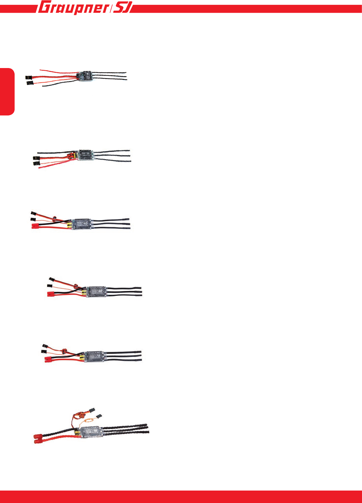
Brushless Control+T
Controller with internal HoTT
telemetry for brushless motors
33718 BRUSHLESS CONTROL +T 18 BEC JR
33718.SC BRUSHLESS CONTROL +T 18 BEC SC
33718.SH BRUSHLESS CONTROL +T 18 BEC SH
33735 BRUSHLESS CONTROL +T 35 G 3,5
33735.G2 BRUSHLESS CONTROL +T 35 G2
33745 BRUSHLESS CONTROL +T 45 G3,5
33745.G2 BRUSHLESS CONTROL +T 45 G 2
S3046 BRUSHLESS CONTROL +T 50 G 3,5
33760 BRUSHLESS CONTROL +T 60 G 3,5
S3031 BRUSHLESS CONTROL +T 60,Opto, D 3,5
S3040 BRUSHLESS CONTROL +T 60, HV, D 3,5
33770 BRUSHLESS CONTROL +T 70 G 3,5
33770.D35 BRUSHLESS CONTROL +T 70 D3,5 XT-60
S3041 BRUSHLESS CONTROL +T 80, HV, D 3,5
S3042 BRUSHLESS CONTROL +T 80,Opto, D 3,5
S3030 BRUSHLESS CONTROL +T 100, G 6
S3036 BRUSHLESS CONTROL +T 100, HV, G 6
S3037 BRUSHLESS CONTROL +T 100, Opto, G 6
S3038 BRUSHLESS CONTROL +T 120, HV,G 6
S3032 BRUSHLESS CONTROL +T 120,Opto, G 6
S3033 BRUSHLESS CONTROL HV +T 160, Opto G6
S3039 BRUSHLESS CONTROL HV +T 160, G6
S3064 BRUSHLESS CONTROL HV +T 160 COOL
English
32
33718 BRUSHLESS CONTROL +T 18 BEC JR
33718.SC BRUSHLESS CONTROL +T 18 BEC SC
33718.SH BRUSHLESS CONTROL +T 18 BEC SH
33735 BRUSHLESS CONTROL +T 35 G 3,5
33735.G2 BRUSHLESS CONTROL +T 35 G2
S3046 BRUSHLESS CONTROL +T 50 G 3,5
33745 BRUSHLESS CONTROL +T 45 G3,5
33745.G2 BRUSHLESS CONTROL +T 45 G 2
33760 BRUSHLESS CONTROL +T 60 G 3,5
33770 BRUSHLESS CONTROL +T 70 G 3,5
33770.D35 BRUSHLESS CONTROL +T 70 D3,5 XT-60
S3030 BRUSHLESS CONTROL +T 100 G 6

English
3
INNOVATION & TECHNOLOGIE
2
S3033 BRUSHLESS CONTROL HV +T 160, Opto G6
S3039 BRUSHLESS CONTROL HV +T 160, G6
S3041 BRUSHLESS CONTROL +T 80, HV, D 3,5
S3042 BRUSHLESS CONTROL +T 80,Opto, D 3,5
S3038 BRUSHLESS CONTROL +T 120, HV,G 6
S3032 BRUSHLESS CONTROL +T 120,Opto, G 6
S3031 BRUSHLESS CONTROL +T 60,Opto, D 3,5
S3040 BRUSHLESS CONTROL +T 60, HV, D 3,5
S3036 BRUSHLESS CONTROL +T 100, HV, G 6
S3037 BRUSHLESS CONTROL +T 100, Opto, G 6

English
54
Contents
Preamble .........................................................................................................................................5
Symbols and their meanings.........................................................................................................5
Intended usage ...............................................................................................................................6
Available Telemetry Information ...................................................................................................6
Set contents ....................................................................................................................................7
Specication ...................................................................................................................................7
Safety notes ....................................................................................................................................8
Environmental protection notes ................................................................................................. 11
Care and maintenance ................................................................................................................. 11
Connecting the speed controller BRUSHLESS CONTROL +T 18 - 100 ...................................12
Connecting the speed controller BRUSHLESS CONTROL+T 60 - 160, HV .............................12
Connecting the speed controller BRUSHLESS CONTROL HV+T 60 - 160, Opto....................13
Side connections of the BRUSHLESS CONTROL+T 60-160, HV .............................................13
Installing in the model, rst use ..................................................................................................14
Calibrating the transmitter travels for full-throttle and motor off ............................................14
Calibrating the transmitter travels for full-throttle - neutral - brake (or reverse) ..................15
LED status during operation .......................................................................................................15
Settings - Programming ...............................................................................................................15
Setting the motor brake on surface, boat and vehicle models ................................................23
ESC Data View ..............................................................................................................................24
Setup structure - Programming warning thresholds ................................................................24
Graphic display of telemetry data ...............................................................................................27
Firmware Update ..........................................................................................................................28
Declaration of conformity ............................................................................................................30
Notes..............................................................................................................................................31
Warranty ........................................................................................................................................32
English
5
INNOVATION & TECHNOLOGIE
4
Preamble
Thank you for choosing a Graupner Brushless
Control+T speed controller. This controller is extre-
mely versatile and can be used by both beginners and
experts.
Please read this manual carefully, to achieve the best
results with your speed controller, and especially to steer
your models safely. If any difculties arise during use,
consult the manual, contact your dealer, or contact the
Graupner Service Center.
Due to technical changes, the information within this ma-
nual may be changed without prior notication.
This product complies with the national and European
legal requirements.
To maintain this condition and to ensure safe ope-
ration, you, as the user, must read and observe this
operating manual and the safety instructions, before
using it for the rst time!
NOTE
This operating manual is a part of this
product. It contains important instruc-
tions on rst use and handling. Therefo-
re, please keep this operating manual for
future reference! Make sure that this is complied with
when passing on this product to third parties.
All company names and product names herein are trade-
marks of their respective owners. All rights reserved.
If you have technical questions, please contact our ser-
vice, see page 32.
Symbols and their meanings
!
ATTENTION
This symbol emphasizes the adjoi-
ning or following information that the
user must observe! If these empha-
sized instructions are not followed,
safe functioning and the safety of the
operator might be impaired.
!
WITHOUT a specic heading, this
symbol indicates adjoining or subse-
quent information or advice that the
user should strictly observe! If these
instructions and suggestions are not
followed, damage of any kind can
result.
!
WARNING
This symbol calls attention to prohi-
bitions which must be strictly obser-
ved by the user! Any disregard for
the accompanying prohibitions can
impair functionality and impair the
safety the operator.
P
CARE AND MAINTENANCE
This symbol calls attention to notices
regarding care and maintenance of
the product which should be strictly
observed by the operator, in order
to ensure a long service life for the
product
NOTE
This symbol calls attention to notices
which should be strictly observed by
the operator to ensure safe operation
of the device.
TIP
This symbol calls attention to tips
and expertise on how to avoid poten-
tial difculties or damage, and is an
aid for solving potential problems.
DISPOSAL NOTE
This symbol calls attention to the
following notices on how individual
materials and products must be dis-
posed of by the user!
!
ATTENTION!
You must read these instructions in
full before using the speed controller
for the rst time.
Please comply with the instructions
on disposal and environmental pro-
tection on page 11

English
76
Intended usage
The BRUSHLESS CONTROL +T controls the rotational speed of a brushless electric motor con-
nected to it. Precise information regarding your speed controller and suitable motors can be found
under Point 11 in the Specication. The BRUSHLESS CONTROL +T is designed exclusively for
use in radio-controlled models powered by dry or rechargeable batteries; no other type of use is
permitted. Using the controller incorrectly, or for any purpose other than that described, invalidates
our guarantee. In such cases we accept no liability.
The unit also features a telemetry function, although this is only available in conjunction with a
Graupner/SJ HoTT 2.4 system.
If you do not have the Graupner/SJ HoTT 2.4 radio system the telemetry function will not work.
Please read through this entire manual before you attempt the installation and usage of your
BRUSHLESS CONTROL +T!
These operating instructions are part of this product. They contains important notes to the operati-
on and handling. Please take this into consideration when you pass on the product to third parties.
Neglect of the operating instructions and the safety instructions lead to expiring the warranty.
Graupner/SJ constantly work on the advancement of all remote control systems; changes of the
scope of delivery in form, technology and equipment we must reserve ourselves therefore. Please
have understanding for the fact that from data and illustrations of this operating instructions no
requirements can be derived.
Please keep these instructions for further reference!
• BRUSHLESS CONTROL +T features
• Fully proportional forward with on/off brake and reverse
• Smooth throttle response
• Perfect compatible with both inrunner and outrunner motors without setting.
• Motor rotation direction can be set.
• Li-Po, NiCd and NiMH battery compatible
• Selectable model type (Air, Heli, Boat, Car))
• Brake programmable
• Governormode ON / OFF with Governor Speed (only heli)
• Oneway or twoway (Boat and car)
• Automatically sets low-voltage cutoff based on input voltage
• 32 kHz switching frequency
• Thermal cutoff
• Auto store on the stick Position
• adjustable motortiming
Available Telemetry Information
Telemetry screen: - Battery voltage, minimum voltage
- ESC temperature, maximum ESC temperature
- Current, maximum current (except 33718, 33718.SC, 33718.SH)
- BEC voltage, minimum BEC voltage
- RPM, maximum RPM
- Used capacity (except 33718, 33718.SC, 33718.SH)
Programmable warning thresholds for battery voltage, BEC voltage, current consumption, capacity
and ESC temperature (Power consumption and capacity not in 33718, 33718.SC, 33718.SH)

English
7
INNOVATION & TECHNOLOGIE
6
Specication
BRUSH-
LESS
CON-
TROL +T
18
#33718
BRUSH-
LESS
CON-
TROL +T
35
#33735
BRUSH-
LESS
CON-
TROL +T
45
#33745
BRUSH-
LESS
CON-
TROL
+T 50
#S3046
BRUSH-
LESS
CON-
TROL +T
60
#33760
BRUSH-
LESS
CON-
TROL +T
70
#33770
BRUSH-
LESS
CON-
TROL +T
100
#S3030
BRUSH-
LESS
CON-
TROL
+T 60
Opto
#S3031
BRUSH-
LESS
CON-
TROL +T
60HV
#S3040
Cell count
(LiPo)
2 - 4 2 - 6 2 - 6 2 - 6 2 - 6 2 - 6 2 - 6 5 - 12 5 - 12
Operating
voltage
6 - 16,8V
DC 6 - 25V
DC 6 - 25 V
DC 6 - 25 V
DC 6 - 25 V
DC 6 - 25 V
DC 6 - 25 V
DC 16 - 50 V
DC 16 - 50V
DC
Cont. cur-
rent
18 A 35 A 45 A 50A 60 A 70 A 100 A 60 A 60 A
PWM fre-
quency
32 kHz 32 kHz 32 kHz 32 kHz 32 kHz 32 kHz 32kHz 32 kHz 32 kHz
BEC cont.
current
2 A 2 A 3 A 3A 3 A 3 A 3 A -5 A
BEC max.
current
3 A 3 A 10 A 6A 10 A 10 A 10 A -15 A
BEC vol-
tage
5,6V 5.0...8,0
V* 5.0...8,0
V* 5.0...8,0
V* 5.0...8,0
V* 5.0...8,0
V* 5,0...8,0
V* - 5,0...8,0
V*
False start
protection
yes yes yes yes yes yes yes yes yes
Overtemp.
protection
yes yes yes yes yes yes yes yes yes
Low volta-
ge cutoff
yes yes yes yes yes yes yes yes yes
updatetable
rmware
yes yes yes yes yes yes yes yes yes
Dimensi-
ons (mm)
Lenght
without
capacitor
38x23x8 40x26
x10 55 x 30
x 10 48x26
x8,5 55 x 30 x
10 55 x 30
x 10 40x25
x9,5 87x36
x21 87x36
x21
Weight
(with cable)
16 g 44 g 66 g 50g 69 g 73 g 75 g 118 g 118 g
Set contents
• Brushless Control+T controller
• Capacitor for BEC voltage stabilization (note chapter „Installing in the model, rst use“)
• Manual

English
98
BRUSH-
LESS
CONTROL
+T80 Opto
#S3042
BRUSH-
LESS
CONTROL
+T 80 HV
#S3041
BRUSH-
LESS
CONTROL
+T 100
Opto
#S3037
BRUSH-
LESS
CONTROL
+T 100 HV
#S3036
BRUSH-
LESS
CONTROL
+T 120
Opto
#3032
BRUSH-
LESS
CONTROL
+T 120 HV
#S3038
BRUSH-
LESS
CONTROL
+T 160
Opto
#S3033
BRUSH-
LESS
CONTROL
+T 160 HV
#S3039
#S3064
Cell count
(LiPo)
5 - 12 5 - 12 5 - 12 5 - 12 5 - 12 5 - 12 5 - 12 5 - 12
Operating
voltage
16 - 50V
DC 16 - 50V
DC 16 - 50V
DC 16 - 50V
DC 16 - 50V
DC 16 - 50V
DC 16 - 50V
DC 16 - 50V
DC
Cont. current 80 A 80 A 100 A 100 A 120 A 120 A 160 A 160 A
PWM fre-
quency
32 kHz 32 kHz 32 kHz 32 kHz 32 kHz 32 kHz 32 kHz 32 kHz
BEC cont.
current
-5 A -5 A -5 A -5 A
BEC max.
current
-15 A -15 A -15 A -15 A
BEC voltage - 5.0...8,0
V* - 5.0...8,0
V* - 5.0...8,0
V* - 5.0...8,0
V*
False start
protection
yes yes yes yes yes yes yes yes
Overtemp.
protection
yes yes yes yes yes yes yes yes
Low voltage
cutoff
yes yes yes yes yes yes yes yes
updatetable
rmware
yes yes yes yes yes yes yes yes
Dimensions
(mm) Lenght
without capa-
citor
87x36x21 87x36x21 87x36x21 87x36x21 87x36x27 87x36x27 87x36x27 87x36x27
Weight (with
cable)
118 g 118 g 118 g 118 g 165 g 165 g 165 g 165 g
Safety notes
In the event of damages caused by failure to observe these operating instructions,
the guarantee/warranty expires. We do not accept any liability for consequential
damages!
In case of material damage or personal injury resulting from improper use or non-
observance of the safety instructions, we accept no liability! In such cases, the guarantee/
warranty expires.
You have purchased a speed controller, which, together with the required accessories and
a functioning RC model, can be used for remote control operation. Graupner|SJ GmbH is
not able to monitor the compliance with the installation and operating instructions as well
as the conditions and methods used for installation, operation, use and maintenance of
the remote control components. Therefore, Graupner|SJ GmbH does not accept any liabili-
ty for loss, damage or costs arising from improper behaviour as well as improper use and
operation or which are related to this in any way. Unless mandated by prevailing law, the
!

English
9
INNOVATION & TECHNOLOGIE
8
obligation of Graupner|SJ GmbH to provide damage compensation arising from the use of
the product, regardless of the reason, is excluded (this exclusion includes personal injury,
death, damage to buildings or structures as well as sales and business losses, consequen-
tial damage due to business interruption or other direct or indirect consequential dama-
ges). Joint liability under all circumstances and in each case is limited to the amount you
actually paid for this product.
Also excluded from guarantee and warranty are normal wear during operation (e. g. worn gears or
servo gearboxes) and accidental damages (e. g. broken axles or other damages).
The safety instructions do not only serve as a protection of the product, but also for your safety
and that of other persons. Therefore, please read this chapter carefully, before you use the product
for the rst time!
General
Before starting remote control operation, you must inform yourself about the legal provisions, since
it is subject to the applicable laws. You must always observe the laws. In this respect, pay attention
to the laws applicable in the respective country.
A liability insurance is recommended and mandatory for all types of aircraft models. If you already
have one, please inform yourself if the operation of the respective model is covered by your insu-
rance. If this is not the case, conclude a special liability insurance policy for models.
This product is not a toy. It is not suitable for children under 14 years of age.
If you have not yet sufcient knowledge about handling radio-controlled models, please contact an
experienced model enthusiast or a model-making club.
Due to safety and licensing reasons (CE), any unauthorized reconstruction and/or modication of
the product is prohibited.
The product must not become damp or wet. Never operate it in adverse weather conditions, such
as rain, storm, strong wind, etc.
Do not carelessly leave the packaging material lying around, since it might become a dangerous
toy for children.
If you have questions which cannot be answered by the operating manual, please contact us (con-
tact information see page 32) or another expert in the eld.
Operation and use of radio-controlled models needs to be learnt! If you have
never operated a model of this type before, start carefully and make yourself
familiar with the model‘s reactions to the remote control commands. Be patient!
Instructions and warnings
Technical defects of an electrical or mechanical nature may cause motors to start without war-
ning, or may generate ying parts which can cause signicant injury to you and others!
It is imperative to avoid short-circuits of any kind! Short-circuits can destroy parts of the remote
control system and cause serious burns or explosions depending on the circumstances and the
battery charge status.
All parts driven by the motor such as air and water propellers as well as helicopter rotors, exposed
gears, etc. always pose an injury hazard. Never touch these parts! A fast-rotating propeller can, for
example, cut off a nger!
Make sure that no other objects come into contact with driven parts!
Once the battery is connected or the motor is running, always maintain a safe distance from the
hazard area posed by the propulsion system!
Also while programming, make sure that a connected electric motor cannot accidentally start. Dis-

English
1110
connect the drive battery beforehand.
Protect all equipment from dust, dirt, moisture and other foreign parts. All equipment must be pro-
tected from vibration as well as excessive heat or cold. The models may only be operated remotely
under „normal“ outside temperatures, i.e. from -10°C to +55°C.
Avoid any impact and pressure load. Always check the devices on damage to the housing and
cables. Devices that have become wet or damaged must not be used anymore, even if they have
dried out!
Only the components and accessories recommended by us are allowed to be used. Always use
matching, original Graupner plug-in connections of the same design and material.
When routing the cables, make sure that they are not under tension, excessively kinked, or bro-
ken. Sharp edges can also damage the insulation.
Make sure that all of the plug-in connections are tight. When disconnecting the plug-in connec-
tions, do not pull at the cables.
The devices must not be modied in any way. Modications will void the type approval and any
insurance coverage. If necessary, send the relevant device to the responsible Graupner service;
see page 32.
Warnings
The CE certicate of the speed controller does not release from the obligation to exer-
cise extreme caution.
If the motor does not start as desired, or in case of a crash, immediately set the trans-
mitter stick in motor position off, in order to avoid an overload of the speed controller.
Check the correct connection of the motor again, perhaps shorten the cables and, if necessary, set
a time delay for the throttle response at the transmitter, in order to avoid timing errors.
Only use motors from GM-Racing or Graupner/SJ, which are designed for the used voltage range!
Only use high performance batteries from GM-Racing or Graupner/SJ. If the internal resistance of
the batteries is too high, the speed controller can be destroyed! Never use a power supply unit as
a power supply!
Never leave your RC model unattended, as long as the battery is connected. In case of a malfunc-
tion, this could cause re at the model or in its surroundings.
The speed controller or other electronic components must never come into contact with water. Pro-
tect the speed controller from dust, dirt, moisture, vibration and other foreign parts.
Never run the motor with a separate battery. This destroys speed controller and motor and voids
the warranty.
Never reverse the polarity of your speed controller. Use polarity-safe plug-in systems. Avoid short-
circuits and blocking motors.
All cables and connections must be well insulated. Short-circuits can destroy your speed controller.
The speed controllers are only intended for use in radio-controlled models that are driven by bat-
teries or rechargeable batteries. Any other use is not permitted. The use in a model for passenger
transport is prohibited!
Motors, gearboxes and propellers for boats and aircraft are dangerous objects. Therefore, never
get next to or in front of the danger zone of the driving mechanism!
Technical defects of mechanical or electrical parts can cause the motor to start inadvertently and
lead to ying parts, which can cause serious injuries.
First, always perform a range and function test on the ground (to do so, hold your model tight),
before you use your model. Repeat the test with running motor and with short throttle bursts.
No modications whatsoever may be made to the speed controller, unless they are described in
the instructions.
Only the components and accessories recommended by us are allowed to be used. Always use
matching, original GRAUPNER/SJ plug-in connections and accessories.
Before each start-up and before you plug in the speed controller, make sure that: your transmitter
!

English
11
INNOVATION & TECHNOLOGIE
10
is switched on and that the throttle lever is set to the position STOP.
Disclaimer: Graupner/SJ is not able to monitor the compliance with the installation and operating
instructions as well as the conditions and methods used for installation, operation, use and mainte-
nance of the speed controller.
Therefore Graupner/SJ does not accept any liability for loss, damage or costs arising from impro-
per use and operation or which are related to it in any way.
Environmental protection notes
The symbol on this product, its operating instructions or packaging gives notice that
this product may not be discarded as common household waste at the end of its service
life. It must be turned over to a recycling collection point for electric and electronic
apparatus. The materials can be recycled according to their markings. You make an
important contribution to protection of the environment by utilizing facilities for reuse,
material recycling or other means of exploiting obsolete equipment. Batteries must be
removed from the unit and disposed of separately at an appropriate collection point. Please inquire
with local authorities about the responsible waste collection locations.
Care and maintenance
P
CARE INSTRUCTION
The controller is entirely maintenance-free and therefore requires no servicing of
any kind. However, it is in your own interests to protect the controller from dust,
dirt and moisture.
To clean the controller, disconnect it from the battery pack and gently wipe it clean with a
dry cloth only (do not use any cleaning agents).

English
1312
Telemetriekabel
„Master“ Throttle
channel with BEC
„Slave“ Updatechannel
with 2. BEC
Battery connector
Motor connectors
C
B
A
The speed controller provides stable voltage supply to the receiver with BEC continuous current
rating of 5A and peak power load of 15 A. In order to achieve the optimum power, the speed con-
troller is equipped with two BEC connectors. The „master“ connection must be connected to the
throttle channel of the receiver. The „slave“ connection is the second BEC power supply and co-
mes with a free channel of the receiver, use this best each of the outer terminals (Bat. port), or a
ybarless system, etc. connected. The „slave“ connection is also to be used for the update cable.
To update, you proceed as described in Chapter „rmware update“ before, but differing use the
„slave“ connection.
Connecting the speed controller BRUSHLESS CONTROL+T 60 - 160, HV
Battery leads may be supplied with different connector systems. You can avoid this problem by
always using Graupner/SJ batteries tted with matching connectors. The maximum length of the
ight battery leads is 20 cm. The motor is connected to the speed control of the three black cord.
The cables are equipped with jacks. Therefore, should be attached to the engine the right plug. The
motor cable can alternatively be soldered directly.
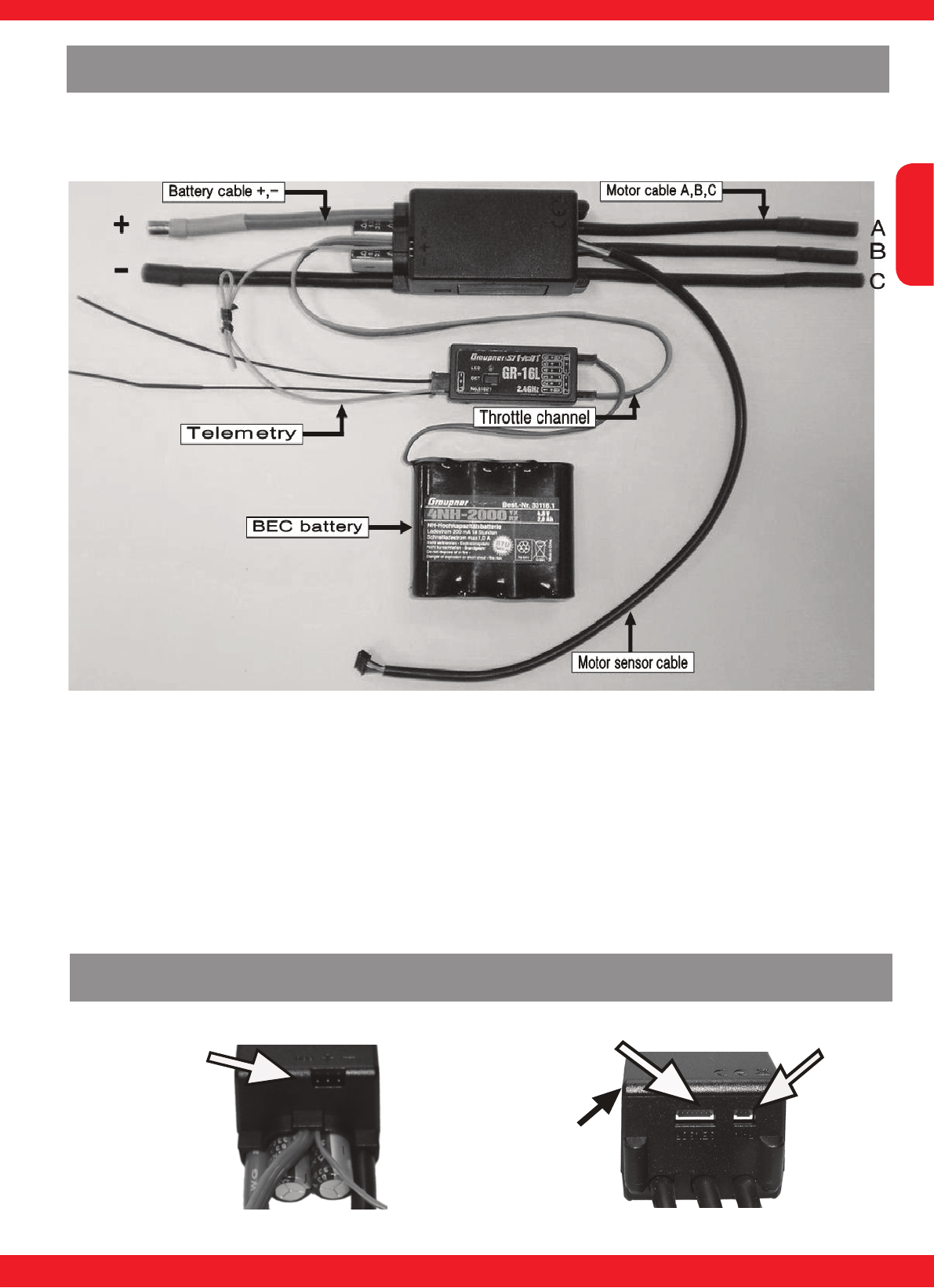
Connecting the speed controller BRUSHLESS CONTROL +T 18 - 100
Battery 7.2 - 22.2 V DC
Receiver channel 1
Telemetry socket „T“
Drive motor with
G3.5 connectors
orange
Heatsink
English
13
INNOVATION & TECHNOLOGIE
12
The speed controller feature an optocoupler to the signal input side (gas passage). That means the
connected receiver requires a separate power supply because no BEC is present in the system, ie
the controller supplies no voltage to the receiver. (see illustration)
Connecting the speed controller BRUSHLESS CONTROL HV+T 60 - 160, Opto
When selecting the receiver battery, note that you need to have adequate battery capacity for all
servos to provide sufcient power. Pay attention also to a corresponding cross -section of the battery
connection cable so under high load the voltage can not collapse. Especially when using a large
number of servos it is recommended to connect the power supply to the receiver via two entrances.
Here you have the two outer ports, which are marked on the receiver with a ‚B‘. If you connect a
separate battery pack to each battery terminal, make absolutely sure that the batteries have the
same rated voltage and capacity. Do not connect different types of batteries or batteries with highly
different charging states, because this may lead to short-circuit-like effects. Use in such cases, for
safety reasons, voltage stabilizers like the PRX-5A-receiver power supplies (No. 4136) between the
battery and receiver.
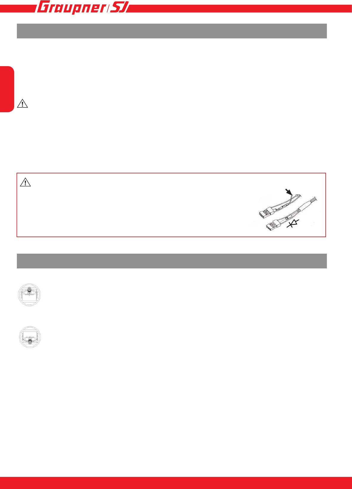
„Slave“ Update-
channel with
second BEC
Sensor connector Fan connector
Motor connectors side
Battery connector side
Status LED
yellow / red
Side connections of the BRUSHLESS CONTROL+T 60-160, HV
English
15
14
Mount the speed controller in the model so that it is isolated from vibration and shock and make sure
the heatsink is free for best cooling. Make sure that there is suf cient cooling of the motor and speed
controller by directing adequate cooling air from the outside air ow.
• Turn the transmitter on and check the servo travel of the throttle channel which should be ±100%
or, with Multiplex R/C systems, ±80%. Robbe/Futaba systems need reversing (REVERSE) the
throttle arm travel! With Graupner/JR/SJ systems, the latter should be set to “NORMAL”.
WARNING: the BEC voltage of the speed controller is adjustable from 5 to 8 V. The factory
setting is 5.6 V and works for all receiver and servos. A voltage above 5.6 V may only be pro-
grammed when the receiver and all connected servos are suitable for this voltage, eg. high-voltage
servos! Risk of re!
Capacitor for BEC (included)
Use the supplied capacitor to stabilize the BEC voltage by plugging it into an available channel of the
receiver. The capacitor bridges short voltage dips at peak times.
Warning: If you do not want to use the BEC supply from the cont-
roller and instead use a separate battery, you have to remove and
isolate the red wire (+) of the BEC plug as shown in the sketch. This will
prevent a back ow into the controller, which could destroy the control-
ler. If you want to connect a battery to the BEC system, a diode (e.g.
Schottky diode 91505) needs to be soldered into the BECs red wire, so
that the current can only ow from the BEC to the receiver.
Calibrating the transmitter travels for full-throttle and motor off
1. Switch the transmitter on (“ON”), then move the throttle stick to the “full-throttle” posi-
tion and hold it there.
2. Connect the dry / rechargeable battery to the speed controller with correct polarity.
When all the leads are correctly inserted, the motor emits a brief beep to con rm that
the power supply is connected.
3. After about ten seconds you hear a brief melody (di-da-di), and both LEDs (red and
yellow) ash to indicate that the speed controller has detected the full-throttle position.
4. Move the throttle stick to the motor OFF position (back towards you) within four se
conds: the motor emits a brief beep (di-da), and both LEDs ash. Hold the throttle
stick in that position until you hear a brief melody - only the yellow LED lights
up - to indicate that the speed controller has detected and stored the motor OFF posi
tion.
5. Full-throttle and motor OFF are now programmed; disconnect the power supply from
the speed controller in order to store the settings.
Installing in the model, rst use
(+) red

English
15
INNOVATION & TECHNOLOGIE
14
Calibrating the transmitter travels for full-throttle - neutral - brake (or reverse)
1. Switch the transmitter on (“ON”), then move the throttle stick to the “full-throttle” posi
tion and hold it there.
2. Connect the dry / rechargeable battery to the speed controller with correct polarity.
When all the leads are correctly inserted, the motor emits a brief beep to indicate that
the power supply is connected.
3. After about ten seconds you hear a brief melody (di-da-di), and both LEDs (red and
yellow) ash to indicate that the speed controller has detected the full-throttle position.
4. Move the throttle stick to the neutral position (e.g. centre) within four seconds. The
motor emits a brief beep (di-da), and the yellow LED ashes to indicate that the
speed controller has detected the neutral position.
5. Move the throttle stick to the bottom position (back towards you) within six seconds.
The motor emits a brief beep (di-da), and both LEDs ash. Hold the throttle stick in
that position until you hear a brief melody - only the yellow LED lights up - to indicate
that the speed controller has detected the motor OFF position.
6. Full-throttle - neutral - brake - reverse are now programmed; disconnect the power
supply from the speed controller in order to store the settings.
Note: the ‘reverse’ function is only available in ‘Boat’ and ‘Car’ mode, and must be
activated separately at the transmitter when calibration is complete. For more infor
mation please refer to the section entitled ‘Settings’.
LED status during operation
Function yellow LED red LED
Neutral on off
Full throttle off on
Full brake on on
Reverse off off
Nr. LED Error
1Yellow LED ashes
1 x Throttle stick not at neutral or reverse
position, check program-
ming if necessary
2Red LED ashes 1 x no signal
3Red LED ashes 2 x Battery voltage too low
4Red LED ashes 3 x Temperature of speed controller too
high
5Red LED ashes 4 x Current too high
6Red LED ashes 5 x Sensor error of sensored motor
7Red LED ashes 6 x - Check motor, it is a motor problem
when use sensored motor.
- If error shows when power is get-
ting on, please send the product to
our service department.
8 Yellow and red LED
ashes 1 x
- Searching model*
The error messages are retained until the speed controller is discon-
nected from the battery. The exception is message No. 2, which dis-
appears as soon as the speed controller picks up a valid signal again.
* Error message 8 - model search:
When the throttle stick is below the pro-
grammed end position or braking position,
the controller will beep after 30 seconds
the engine and blink the two LEDs on the
controller. This serves to nd a crashed
and lost model better. Enable this function
by setting M.Lost_beep-Funktion „on“ in
the „User setup“ menu on page 5.
The volume of the tone is adjusted by
„Beep level“.
Settings - Programming
The BRUSHLESS CONTROL +T series of speed controllers can be programmed either directly
using the transmitter, or via the telemetry settings if you are using a Graupner/SJ HoTT RC sys-
tem.

English
1716
Yellow
LED Mode
Red LED
1 2 3 4 5 6 7 8 9 10 11
1 Battery type LiPo NiMH
2 Rotation normal reverse
3
Auto brake
(xed wing
models) in% 0 10 20 30 40 50 60 70 80 90 100
Governor
(helicopter) off on
Reverse
function
(boat/car) oneway twoway
4* Motortype Sensor-
less Sensor
5 Model type plane heli boat car
6 factory reset no yes
*For controllers without sensor connection mode Void 4, 5 becomes 4, and 6 to 5.
Settings in programming mode (without HoTT radio control system)
Start by programming the speed controller as described under “Calibrating the transmitter travels”,
working through as far as Point 4 or 5.
Move the stick to the full-throttle position again, and hold it there for at least six seconds: the speed
controller now beeps ve times to indicate that it is in programming mode.
The mode (1 - 5) is indicated by the yellow LED, the parameters by the red LED. The LEDs ash
to indicate the settings, e.g. 2 x ashes of the yellow LED equates to mode 2 (direction of rotation),
1 x ash of the red LED equates to normal (direction of rotation).
To set the mode, move the throttle stick to the Stop / Reverse position (throttle stick right back),
then return it to the “full-throttle” position to switch to the next mode. The switch is conrmed by 2 x
beeps.
When you are in the desired mode, move the throttle stick to the Stop / Reverse position for two
seconds: you can now program the parameters.
The red and yellow LEDs ash simultaneously, according to the set parameter.
You can now program the parameter by alternating between “full-throttle” and Stop / Reverse; ad-
vancing the throttle increases the value by one.
When you reach the desired value, store the setting by holding the throttle stick at the full-throttle
position for at least two seconds. The speed controller beeps 3 x as an audible conrmation.
Repeat the procedure for all the remaining parameters which you wish to program, starting in each
case at Point 3.
When everything is programmed to your satisfaction, store the settings by disconnecting the power
supply from the speed controller.
Note: the settings in mode 3 vary according to the model type (mode 4). It is therefore essential to
program the model type rst!

English
17
INNOVATION & TECHNOLOGIE
16
Settings in programming mode (with HoTT radio control system)
The method of operating the HoTT transmitter. For more information please read the section entitled
“Telemetry” in the operating instructions supplied with your radio control system. Programming is
carried out in the transmitter’s “Telemetry” menu under the menu point “SETUP / DISPLAYS”. The
sensor displays come next in sequence after the transmitter - receiver displays, i.e. the “ESC DATA
VIEW” display follows the last display of the RC system’s servo test (RX SERVO TEST). Please
note the following: the menus can only be selected if the receiver is switched on! When you switch
the receiver on, it may take a few seconds for the display to become active - i.e. before you can se-
lect it. There might be a slight delay in the screen’s response to inputs, as all settings are transferred
directly to the receiver / speed controller by wireless means.
Attention! Menu item „Motor“ in page 1 is only visible if the controller has a sensor port for
the engine!
[ESC] DATA VIEW <>
Curr: 5.9Max
Volt: 7.5Min
ESC : 29 Max
BEC : 5.4Min
RPM : 0Max 0
Capacity: 0mAh
ERROR:
3.0A
7.6V
28 C
5.5V
[ESC] WARNING <>
>Set warning :
>E.S.C save?
>Factory set?
>Ver:P 1.000
page 1
No
No
[ESC] MODEL *AIR <>
>User setup :
>MODEL :
>MOTOR : SENSORLESS
: SENSOR
E.S.C save?
>Factory set?
>Ver:P 1.000
page 1
Air
No
No
[ESC] MODEL *AIR <>
>User setup :
>MODEL :
MOTOR : SENSORLESS
: SENSOR
E.S.C save?
>Factory set?
Ver:P 1.000
page 1
Air
No
No
[ESC] MODEL *AIR <>
>User setup :
>Battery :
>Cut_off :
>Cut_type :
>Rotation :
>Motor timing:
page 2
LiPo
Auto
Soft
Normal
25
Fixed wing model:
[ESC] MODEL *AIR <>
>User setup :
>Speed up typ:
>Start torque:
>A-Brake :
>Min.Brake :
>Max.Brake :
Brake Type :
page 3
Normal
Lowest
0%
0%
100%
Normal
[ESC] MODEL *AIR <>
>User setup :
>Number-pole :
>Gear Ratio :
>BEC Volt :
>
BEC :
page 4
2
1.0:1
5.6V
5.45V
In Opto controllers menu the item
„BEC Volt“ does not exist!
[ESC] MODEL *Air <
>User setup :
>Beep Level :
>M.LoSt_beep :
>
page 5
5
on
[ESC] MODEL *Heli <>
>User setup :
>MODEL :
>MOTOR : SENSORLESS
: SENSOR
E.S.C save?
>Factory set?
>Ver:P 1.000
page 1
Heli
No
No
[ESC] MODEL *Heli <>
>User setup :
>Battery :
>Cut_off :
>Rotation :
>Motor timing:
page 2
LiPo
Auto
Normal
25
Helicopter:
[ESC] MODEL *Heli <>
>User setup :
>Speed up typ:
>Start torque:
>Gov speed :
>Gov Response:
>Governor :
page 3
Normal
Lowest
off
Slowest
off
[ESC] MODEL *Heli <>
>User setup :
>Number-pole :
>Gear Ratio :
>BEC Volt :
>
BEC :
page 4
2
1.0:1
5.6V
5.45V
In Opto controllers menu the item
„BEC Volt“ does not exist!
[ESC] MODEL *Heli <
>User setup :
>Beep Level :
>M.LoSt_beep :
>
page 5
5
on

English
1918
[ESC] MODEL *Boat <>
>User setup :
>MODEL :
>MOTOR : SENSORLESS
: SENSOR
E.S.C save?
>Factory set?
>Ver:P 1.000
page 1
Boat
No
No
[ESC] MODEL *Boat <>
>User setup :
>Battery :
>Cut_off :
>Cut_type :
>Rotation :
>Motor timing:
page 2
LiPo
Auto
Soft
Normal
25
Boat:
[ESC] MODEL *Boat <>
>User setup :
>Speed up typ:
>Start torque:
>A-Brake :
>Min.Brake :
>Max.Brake :
Brake Type :
page 3
Normal
Lowest
0%
0%
100%
Normal
[ESC] MODEL *Boat <>
>User setup :
>Max-Reverse :
>Reverse func:
>Number-pole :
>Gear Ratio :
>BEC Volt :
BEC :
page 4
100%
oneway
2
1.0:1
5.6V
5.45V
[ESC] MODEL *Car <>
>User setup :
>MODEL :
>E.S.C save?
>Factory set?
>Ver:P 1.000
page 1
Car
No
No
[ESC] MODEL *Car <>
>User setup :
>Max-Reverse :
>Reverse func:
>Number-pole :
>Gear Ratio :
>BEC Volt :
page 4
100%
Twoway
2
1.0:1
5.6V
Car:
These settings are similar to the “Boat” model type, with the exception of the rever-
se (two-way) function, which is activated by default.
Attention: In Opto controllers menu
the item „BEC Volt“ does not exist!
[ESC] MODEL *Car <>
>User setup :
>MODEL :
>E.S.C save?
>Factory set?
>E.S.C RESTART...
>Ver:P 1.000
page 1
Car
Yes
Yes
0
To store the settings in the speed controller, use the INC (p) or DEC
(q) button to return to the “page 1 - ESC MODEL” screen display,
and select the “”E.S.C. save” menu point. Simultaneously pressing
the INC and DEC buttons (SET) highlights the parameter (black
background). Press the INC button (p) to move to YES, and then
store the selected setting by simultaneously pressing the INC and
DEC buttons (SET). An additional line “E.S.C. RESTART” now ap-
pears on the screen, and counts down starting at 3. The settings are
permanently stored when the count reaches 0; “E.S.C. RESTART”
disappears again to conrm this. If you do not wish to save the chan-
ges, select NO.
[ESC] MODEL *Boat <
>User setup :
>Beep Level :
>
page 5
5
[ESC] MODEL *Car <
>User setup :
>Beep Level :
>
page 5
5

English
19
INNOVATION & TECHNOLOGIE
18
Note: the motor will not start if you alter settings but do not store them. This is an additional safety
function to ensure that you do not overlook the ‘saving’ procedure.
The programmable parameters vary according to the selected model type:
Fixed wing models
Parameter Display-Page Description Setup
User setup Page 1 User setup:
Model type, save set-
tings
Air: Fixed wing model
Heli: Helicopter
Boat
Car
Battery Page 2 Battery type LiPo, NiMH
Factory setting: LiPo
Cut_off Cutoff voltage (drive
battery) Auto, 6.0 - 32.0 V (HV/Opto 15 - 50V)
Factory setting: auto
Cut_type Cutoff type soft, hard, Factory setting: soft
Rotation Direction of rotating normal, reverse, Factory setting: normal
Motor timing Motor timing 0 - 25°, Factory setting: 25° (HV/Opto 25°)
Speed up type Page 3 Acceleration lowest, low, normal, high, highest,
Factory setting: normal
Start torque Start torque lowest, low, normal, high, highest,
Factory setting: lowest
A-Brake Automatic brake 0 - 100 %, Factory setting: 0%
Min-Brake Minimum brake 0 - 50 %, Factory setting: 0%
Max-Brake Maximum brake 50 - 100 %, Factory setting: 100%
Brake Type Brake response softest, soft, normal, hard,
Factory setting: normal
Number pole Page 4 Number of motor poles
(important for the cor-
rect speed display)
2 - 36, Factory setting: 2
Gear ratio Gear ratio (important
for the correct RPM
display)
1.0:1 - 25.0:1, Factory setting: 1.0:1
BEC Volt
not in opto version! BEC voltage 5.0 - 8.0 V, Factory setting: 5.6 V
Adjustment not possible with Opto controllers!
Beep Level
Page 5
Tone volume 1-5/off
M.LoSt_beep Tone to nd the lost
model on/off

English
2120
Helicopter
Parameter Display-
page Description Setup
User setup Page 1 User setup:
Model type, save settings Air: Fixed wing model
Heli: Helicopter
Boat
Car
Battery Page 2 Battery type LiPo, NiMH
Factory setting: LiPo
Cut_off Cutoff voltage (drive
battery) Auto, 6.0 - 32.0 V (HV/Opto 15 - 50V)
Factory setting: auto
Rotation Direction of rotating normal, reverse, Factory setting: normal
Motor timing Motor timing 0 - 25°, Factory setting: 25° (HV/Opto 25°)
Speed up type Page 3 Acceleration lowest, low, normal, high, highest,
Factory setting: normal
Start torque Start torque lowest, low, normal, high, highest,
Factory setting: lowest
Gov speed Governor speed (see
below) on/off, Factory setting: off
Gov response Governor response slowest (8 ms), slow (6 ms), normal (4 ms), fast (2 ms), fas-
test (1 ms),
Factory setting: fastest
Governor Governor mode on/off, Factory setting: off
Number pole Page 4 Number of motor poles
(important for the correct
speed display)
2 - 36, Factory setting: 2
Gear ratio Gear ratio (important for
the correct RPM display) 1.0:1 - 25.0:1, Factory setting: 1.0:1
BEC Volt
not in opto ver-
sion!
BEC voltage 5.0 - 8.0 V, Factory setting: 5.6 V
Adjustment not possible with Opto controllers!
Beep level
Page 5
Tone volume 1-5/off
M.LoSt_beep Tone to nd the lost
model on/off
Gov speed: Governor Speed is a further development of the familiar Governor mode. In this case
the motor speed is stored according to the throttle stick position - but regardless of the battery in use
(cell-count, quality). This means that the controller regulates rotational speed according to the load
on the motor, regardless of the state of the battery, i.e. whether it is fully charged or almost at, or
whether - for example - you are using a 4S or 5S battery.
• Governor mode must rst be activated (Governor ON).
• Switch Governor Speed on (ON) - don’t forget to store the setting on page 1, otherwise the motor
will not run.
• Advance the throttle until the desired rotational speed is reached. We recommend a value of 70 -
80%, to ensure that there is a reserve available for the regulatory process. If the motor runs stably
at this speed, the yellow LED on the speed controller ashes briey to indicate that the rotational
speed is now stored.
• To store the value permanently in the speed controller leave the throttle stick at the motor OFF
position for at least three seconds.

English
21
INNOVATION & TECHNOLOGIE
20
Boats
Parameter Display-
page Description Setup
User setup Page 1 User setup:
Model type, save settings Air: Fixed wing model
Heli: Helicopter
Boat
Car
Battery Page 2 Battery type LiPo, NiMH
Factory setting: LiPo
Cut_off Cutoff voltage (drive bat-
tery) Auto, 6.0 - 32.0 V (HV/Opto 15 - 50V)
Factory setting: auto
Cut_type Cutoff type soft, hard, Factory setting: soft
Rotation Direction of rotating normal, reverse, Factory setting: normal
Motor timing Motor timing 0 - 25°, Factory setting: 25° (HV/Opto 25°)
Speed up type Page 3 Acceleration lowest, low, normal, high, highest,
Factory setting: normal
Start torque Start torque lowest, low, normal, high, highest,
Factory setting: lowest
A-Brake Automatic brake 0 - 100 %, Factory setting: 0%
Min-Brake Minimum brake 0 - 50 %, Factory setting: 0%
Max-Brake Maximum brake 50 - 100 %, Factory setting: 100%
Brake Type Brake response softest, soft, normal, hard,
Factory setting: normal
Max-Reverse Page 4 Maximum reverse 20 - 100 %, Factory setting: 100%
Reverse func. Reverse function oneway, twoway,
Factory setting: oneway
Number pole Number of motor poles
(important for the correct
speed display)
2 - 36, Factory setting: 2
Gear ratio Gear ratio (important for
the correct RPM display) 1.0:1 - 25.0:1, Factory setting: 1.0:1
BEC Volt
not in opto ver-
sion!
BEC voltage 5.0 - 8.0 V, Factory setting: 5.6 V
Adjustment not possible with Opto controllers!
Beep level Page 5 Tone volume 1-5/off
Note:
• If you intend to use different batteries, it is important to test-y the Governor Speed using the
“smallest” battery; i.e. if you plan to use 4S and 5S batteries, the setting must be established
using the 4S battery.
• Gaslimitter must be fully open! Before programming, please perform a factory reset!
• Initial start-up and saving process of the speed must not be interrupted, otherwise incorrect speed
is stored. In this case a factory reset must be carried out again.

English
2322
Car models
Parameter Display-
Page Description Setup
User setup Page 1 User setup:
Model type, save set-
tings
Air: Fixed wing models
Heli: Helikocter
Boat
Car
Battery Page 2 Battery type LiPo, NiMH
Factory setting: LiPo
Cut_off Cutoff voltage (drive
battery) Auto, 6.0 - 32.0 V (HV/Opto 15 - 50V)
Factory setting: auto
Cut_type Cutoff type soft, hard, Factory setting: soft
Rotation Direction of rotation normal, reverse, Factory setting: normal
Motor timing Motor timing 0 - 25°, Factory setting: 25° (HV/Opto 25°)
Speed up type Page 3 Acceleration lowest, low, normal, high, highest,
Factory setting: normal
Start torque Start torque lowest, low, normal, high, highest,
Factory setting: lowest
A-Brake Automatic brake 0 - 100 %, Factory setting: 0%
Min-Brake Minimum brake 0 - 50 %, Factory setting: 0%
Max-Brake Maximum brake 50 - 100 %, Factory setting: 100%
Brake Type Brake response softest, soft, normal, hard,
Factory setting: normal
Max-Reverse Page 4 Maximum reverse 20 - 100 %, Factory setting: 100%
Reverse func. Reverse function oneway, twoway, Factory setting: twoway
Number pole Number of motor poles
(important for the cor-
rect speed display)
2 - 36, Factory setting: 2
Gear ratio Gear ratio (important
for the correct RPM
display)
1.0:1 - 25.0:1, Factory setting: 1.0:1
BEC Volt
not in opto version! BEC voltage 5.0 - 8.0 V, Factory setting: 5.6 V
Adjustment not possible with Opto controllers!
Beep level Page 5 Tone volume 1-5/off

English
23
INNOVATION & TECHNOLOGIE
22
Braking effect Graupner T series ESC (air mode)
-10
10
30
50
70
90
110
-100 -80 -60 -40 -20 0
Brake (%)
Brake (%)
Example Min.Brake=20, Max.Brake=90, A-Brake and Brake type
not relevant.
Setting the motor brake on surface, boat and vehicle models
A-Brake (Auto Brake)
In this setting, the braking effect is controlled automatically from 1 to the set value (max. 100 %),
when reaching the braking point on the throttle stick. 0 % means Auto Brake off.
Min and Max Brake settings have no effect.
Brake type settings are effective.
The activation of A-Brake is possible with both teach-in versions for the transmitter travel (see
page 13).
Min-Brake, Max-Brake (minimum braking effect, maximum braking effect)
In this setting, the initial and nal braking effect when reaching the braking point on the throttle
stick is set (see graphic below)
Only effective if Auto Brake on 0 % and full throttle-neutral-brake teach-in version for the transmit-
ter travel (see page 13) has been selected.
Brake type (brake response)
In this setting, the brake response is set.
Setting options in 4 increments: softest, soft, normal, hard.
This means:
softest = braking effect takes effect very slowly; hard = braking effect takes effect quickly (sudden-
ly).

English
2524
ESC Data View
[ESC] DATA VIEW <>
Curr: 5.9Max
Volt: 7.5Min
ESC : 29 Max
BEC : 5.4Min
RPM : 0Max 0
Capacity: 00000 mAh
ERROR:
3.0A
7.6V
28 C
5.5V
The ESC DATA VIEW display shows the telemetry data of the BRUSH-
LESS CONTROL +T. This is not a “live display”, and is suppressed when
the model is actually operating. Use the graphic screen for this - see
„GRAPHIC DISPLAY OF TELEMETRY DATA“
Parameter Description Setup
Curr(ent) The actual current drain of the connected motor, maximum current drain
since switching on (Max) -
Volt Current voltage of the connected battery, minimum voltage since the start
(Min) -
ESC Current temperature of the ESC in °C, maximum temperature since the start
(Max) -
BEC Current BEC voltage, minimum voltage since the start (Min) -
RPM (MAX) Maximum RPM of the connected motor since the start -
RPM (Avg) Average RPM of the connected motor since the start -
Capacity Used capacity of the connected battery since the start -
Error OC: Overcurrent, T: Overheat, V: Low-Tension, R: No receiver signal -
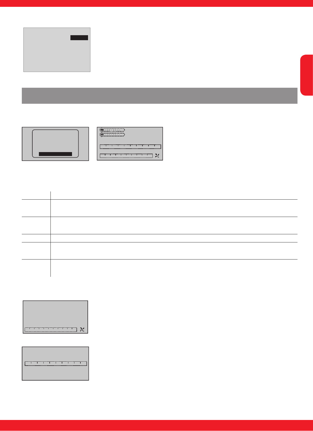
Setup structure - Programming warning thresholds
[ESC] DATA VIEW <>
Curr: 5.9Max
Volt: 7.5Min
ESC : 29 Max
BEC : 5.4Min
RPM : 0Max 0
Capacity: 00000 mAh
ERROR:
3.0A
7.6V
28 C
5.5V
[ESC] WARNING <>
>Set warning :
>E.S.C save?
>Factory set?
>Ver:P 1.000
page 1
No
No
[ESC] VOLTAGE <>
>Set warning :
>Voltage :
>Warning Time:
>Repeat Time :
>Signal Tone :
>Min-Volt :
page 2
6.0V
off
ALWAYS
P
7.5V
p q
If you wish to carry out an adjustment, you must use the INC or DEC buttons (p or q) above the
screen to select the desired parameter (e.g. page 2) by moving the arrow cursor (INC or p moves
the cursor down, DEC oder q moves it up). Simultaneously pressing the INC and DEC (SET) but-
tons switches the parameter
to be adjusted to inverse video (white on black); this indicates that it can be programmed: pressing
the INC (p) button at this point increases the value, pressing the DEC (q) button reduces the value.
When the adjustment is complete, save the selected setting by pressing the INC and DEC (SET)
buttons simultaneously;
the dark background now disappears in order to con rm this action.
Display (Set Warning): shows the various „display pages“ with the possible adjustable parameters
and the
associated adjustable warning thresholds (page 1, page 2, etc.). To switch between pages, press
the INC or DEC key (p or q).
Note:
p and q describes the UP and DOWN
buttons at the transmitter, INC and DEC
describes the UP and DOWN buttons
at the SMART-BOX, SET describes the
ENTER button

English
25
INNOVATION & TECHNOLOGIE
24
Parameter Display-
Page Description Setup
Set Warning Page 1 –
page 6 Parameter Display Page 1 – page 6
Voltage Page 2 Minimum voltage in Volt 6.0 - 32.0V
(HV/Opto 15 - 50V)
Temperature Page 3 Maximum ESC temperature in °C 10 to 120° C
Max. Current Page 4 Maximum current of the connected
motor in A 25 to xxx A
Motor Temp (only with sensor) Page 4 Maximum motor temperature in °C 10 - 120°C
Minimum RPM Page 5 Minimum RPM of the connected motor
in RPM 10 to 100.000 RPM
Capacity Page 6 Maximum capacity 100 - 60000 mAh
Warning Time Page 2 –
page 6 Warning time OFF, 5, 10, 15, 20, 25, 30
sec.
Repeat Time Page 2 –
page 6 Repeat time always, 1, 2, 3, 4, 5 minutes,
one time
Signal Tone Page 2 –
page 6 Sinal tone (voice output)
E.S.C save Page 1 Saves the settings in the speed cont-
roller YES / NO
Factory Set Page 1 Reset to factory setting YES / NO
The following parameters can be set separately for all displays:
Warning Time: sets whether and how long the warning signal is activated when reaching a certain
value for each display screen - OFF deactivates the warning.
Repeat Time: sets how often the warning signal is activated when reaching a certain value for each
display screen.
Signal Tone: sets the signal tone melody. The warning sounds are combined with the warnings on
the display and the voice output. Therefore, they may not be changed.
When a warning is activated, the corresponding message (e.g. VOLTAGE) is shown inver-
ted in the rst row of the associated display and the signal tone respectively voice output
sounds.
If you wish to carry out an adjustment (page 2 to 6) you must use the INC (p) or DEC (q) buttons
above the screen to select „page 1 - ESC WARNING“ and choose „E.S.C save“. Simultaneously
pressing the INC and DEC buttons (SET) switches the parameter to be adjusted to inverse video
(white on black); this indicates that it can be programmed: pressing the INC (p) button at this point
increases the value to YES. When the adjustment is complete, save the selected setting by pressing
the INC and DEC buttons (SET) simultaneously; the dark background now disappears in order to
conrm this action. If you do not want to save the adjustments, select NO.
WARNING: Do not carry out any programming work on the sensors while the model is ying,
otherwise there is a real risk that your model will y out of control while you are not concentra-
ting on it!
If your model is tted with two or more receivers, it is absolutely essential that you do not carry out
programming work during a ight, as this can alter the settings in the receivers to which no telemetry
equipment is connected; in the worst case this could result in the model crashing.
For this reason always carry out programming on the ground, and check that only the receiver with
connected sensors is powered on.

English
2726
Minimum RPM (Page 6)
Minimum RPM: Warning threshold for the minimum RPM, set between 10
and 100.000 RPM.
Factory setting: 100 RPM, Signal tone: T
Warning OFF
[ESC] MINIMUM RPM <>
>Set warning :
>Minimum RPM :
>Warning Time:
>Repeat Time :
>Signal Tone :
> RPM :
page 6
100
off
ALWAYS
T
0
Maximum current (Page 5)
Maximum Current: Warning threshold for the maximum current of the
drive motor, set between 25 and XXX A.
Note: the warning threshold should never be set to a higher value than the
maximum permissible current for your speed controller type, as this would
prevent sensible warnings being generated!
Factory setting: depending on speed controller, Signal tone: W
Warning 5 sec
[ESC] MAX. CURRENT<>
>Set warning :
>Maximum cur :
>Warning Time:
>Repeat Time :
>Signal Tone :
>MAX.CURR :
page 5
100A
5sec
ALWAYS
W
5.3A
Maximum temperature (Page 3)
Maximum ESC Temperature: Warning threshold for the maximum ESC
temperature, set between 10 and 120°C.
Factory setting: 60°C, Signal tone: H
Warning 5 sec
[ESC] TEMPERATURE <>
>Set warning :
>Temperature :
>Warning Time:
>Repeat Time :
>Signal Tone :
>ESC. Temp :
page 3
60 C
5sec
ALWAYS
H
29 C
Maximum motor temperature (Page 4)
Maximum MOTOR Temperature: Warning threshold for the maximum
MOTOR temperature, set between 10 and 120°C.
Factory setting: 100°C, Signal tone: I
Warning 5 sec
[ESC] MOTOR TEMP. <>
>Set warning :
>Temperature :
>Warning Time:
>Repeat Time :
>Signal Tone :
>MOTOR Temp :
page 4
100 C
5sec
ALWAYS
I
29 C
Minimum Voltage (Page 2)
Minimum Voltage: Warning threshold for the minimum battery voltage, set
between 6.0 and 32 V (HV/Opto: 15.0 and 50.0V)
Factory setting: 6.0 V (HV/Opto 18.0V), Signal Tone: P
Warning OFF
[ESC] VOLTAGE <>
>Set warning :
>Voltage :
>Warning Time:
>Repeat Time :
>Signal Tone :
>Min-Volt :
page 2
6.0V
off
ALWAYS
P
7.5V
English
27
INNOVATION & TECHNOLOGIE
26
Capacity (Page 7)
CAPACITY: Warning threshold for the maximum capacity, set between
100 and 60000 mAh.
Factory setting: 2000 mAh, Signal tone: V
Warning OFF
[ESC] CAPACITY <>
>Set warning :
>Capa.warning:
>Warning Time:
>Repeat Time :
>Signal Tone :
>CAPACITY :
page 7
02000
off
ALWAYS
V
00000 mAh
Graphic display of telemetry data
For information on displaying telemetry data please read the instructions supplied with your radio
control system or SMART-BOX.
RX–S QUA: 100%
RX–S ST : 100%
TX–dBm: 33dBm
RX–dBm: 33dBm
RX–SPG.:4.8 TMP
V–PACK: 10ms
CH OUTPUT TYPE:ONCE
EMPFÄNGER
GENERAL
ELECT. AIR
VARIO
GPS
AIR ESC
00
0rpm
0.0A 0.0A
0
0mAh
0( 0)°C
0.0V/ 0.0V
0( 0)°C
This screen displays the data generated by a BRUSHLESS CONTROL +T. Key, reading from top
right:
Value Explanation
VLeft-hand value: actual battery voltage
Right-hand value: actual battery voltage in present power-on period
°C Left-hand value: actual speed controller temperature
Value in brackets: maximum controller temperature in present power-on period
mAh Battery capacity consumed
ACentre and bar display: actual current
Right-hand value: maximum current in present power-on period
rpm Centre an bar display: actual rotation speed of the motor connected to the ESC
Right-hand value: maximum rotational speed in present power-on period
U/min
0
00
RPM display
This screen displays the current rotational speed of the motor connected
to the brushless speed controller.
0.0A
0.0A
0
0mAh
Current / consumption display
This screen displays the actual current consumption, the peak drain which
has occurred in the present power-on period, and the capacity drawn
from the battery connected to the brushless speed controller within the
same period.
English
2928
In the application call up the Speed controller
point in the list on the left-hand side. A dialogue
box now opens, offering the following choices:
“Load automatically” and “Open le”.
If you wish to load the current rmware into the
controller, select Load automatically. The applica-
tion then attempts to download the current rm-
ware via the Internet. Immediately after clicking
on the button the bar starts to ll green from the
left. Connect the speed controller power sup-
ply before the bar is completely lled: a further
dialogue box now opens, in which you should
click on the desired rmware, followed by the
“Open le” button. The application now downloads the le, and loads it into the speed controller. If
you wish the controller to be loaded with special rmware to which you have access as a le, use
“Open le”. Select the appropriate le in the dialogue box which now opens: the bar starts to ll
green. Connect the speed controller power supply before the bar is full, and the application then
transfers the rmware.
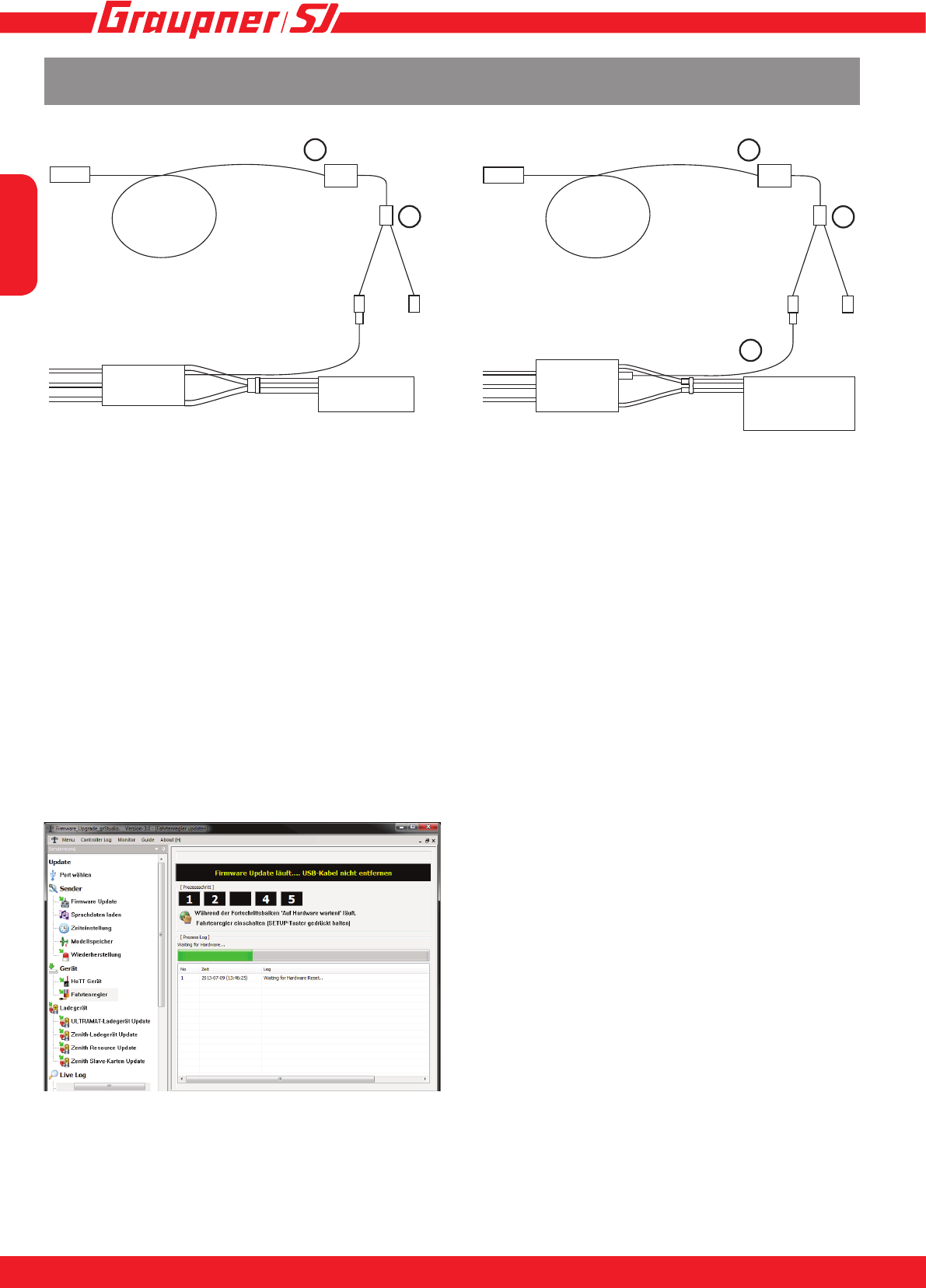
Firmware Update
CONNECTING THE SPEED CONTROLLER PRIOR TO UPDATING
Accessories required:
• (1) USB interface for Graupner/GM-GENIUS, 7166.6
• (2) Adapter cable S8363
• (3) Connection cable 33700.1
For both types of speed controller connect the adapter cable (2) to the USB interface (1). For the
HV and Opto speed controllers the connection cable (3) has to be connected to the socket.
The power supply during the update must be provided through the connection of a battery.
UPDATING THE SPEED CONTROLLER
The user can exploit the update facility to maintain the BRUSHLESS CONTROL +T series speed
controller constantly at the latest state of development, and to add expanded functions in future.
The program required - “Firmware Upgrade gr_studio” - and the update les can be found in the
Download area for the appropriate product at our website www.graupner.de, where they can be
downloaded at no charge.There you will also nd comprehensive instructions for connecting the
BRUSHLESS CONTROL +T prior to updating, and the exact update procedure.
1
2
1
2
3
PC PC
Motor Motor
ESC ESC
Battery
Connection +T 18-100: Connection HV,Opto +T 60-160:
Battery

English
29
INNOVATION & TECHNOLOGIE
28
Contents of the manufacturer’s declaration:
If material defects or manufacturing faults should arise in a product distributed by us in the Federal
Republic of Germany and purchased by a consumer (§ 13 BGB), we, Graupner/SJ GmbH D-73230
Kirchheim/Teck, Germany, acknowledge the obligation to correct those defects within the limitations
described below.
The consumer is not entitled to exploit this manufacturer’s declaration if the failure in the usability of
the product is due to natural wear, use under competition conditions, incompetent or improper use
(including incorrect installation) or external inuences.
This manufacturer’s declaration does not affect the consumer’s legal or contractual rights regarding
defects arising from the purchase contract between the consumer and the vendor (dealer).
Extent of the guarantee
If a claim is made under guarantee, we undertake at our discretion to repair or replace the defective
goods. We will not consider supplementary claims, especially for reimbursement of costs relating to
the defect (e.g. installation / removal costs) and compensation for consequent damages unless they
are allowed by statute. This does not affect claims based on legal regulations, especially according
to product liability law.
Guarantee requirements
The purchaser is required to make the guarantee claim in writing, and must enclose original proof of
purchase (e.g. invoice, receipt, delivery note) and this guarantee card. He must send the defective
goods to us at his own cost, using the following address:
Graupner/SJ GmbH, Service Department,
Henriettenstr.96, D 73230 Kirchheim/Teck, Germany
Service Department: tel. [0049] 7021-722130
The purchaser should state the material defect or manufacturing fault, or the symptoms of the fault,
in as accurate a manner as possible, so that we can check if our guarantee obligation is applicable.
The goods are transported from the consumer to us and from us to the consumer at the risk of the
consumer.
Duration of validity
This declaration only applies to claims made to us during the claim period as stated in this declaration.
The claim period is 24 months from the date of purchase of the product by the consumer from a
dealer in the Federal Republic of Germany (date of purchase). If a defect arises after the end of
the claim period, or if the evidence or documents required according to this declaration in order to
make the claim valid are not presented until after this period, then the consumer forfeits any rights
or claims from this declaration.
Limitation by lapse of time
If we do not acknowledge the validity of a claim based on this declaration within the claim period,
all claims based on this declaration are barred by the statute of limitations after six months from the
time of implementation; however, this cannot occur before the end of the claim period.
Applicable law
This declaration, and the claims, rights and obligations arising from it, are based exclusively on the
pertinent German Law, without the norms of international private law, and excluding UN retail law.
Manufacturer‘s declaration on behalf of GRAUPNER/SJ GmbH

English
3130
Declaration of conformity
14
EU-Konformitätserklärung
EU-Declaration of Conformity
Hiermit bestätigen wir, dass das nachfolgend bezeichnete Gerät den angegebenen Richtlinien entspricht.
We herwith confi rm that the following appliance complies with the mentioned directives.
Artikelbezeichnung:
Article description:
Artikelnummer:
Article number:
Firmenanschrift:
Company adress:
Einschlägige EU-Richtlinien / Governing EU-directives / Directives CE concernées :
1. Elektromagnetische Verträglichkeit (EMV) 2. Niederspannungs-Richtlinie
evitcerid egatlov-woL )CME( ytilibitapmoc citengamortcelE
CE/59/6002 CE/801/4002
3. Maschinenrichtlinie 4. Medizinprodukte (Klasse 1)
)1 ssalC( evitcerid ecived lacideM evitcerid enihsaM
CEE/24/39 CE/24/6002
5. Funkanlagen u. Telekommunikationseinrichtungen 6. Ökodesign-Richtlinie )PrE( evitcerid stcudorp detaler ygrenE tnempiuqE lanimreT noitacinummoceleT .a oidaR
CEE/521/9002 CE/5/9991 ETT&R
7. Beschränkung der Verwendung bestimmter gefährlicher Stoffe in Elektro- und Elektronikgeräten
Restriction of the use of certain hazardous substances
2011/65/EC
Harmonisierte EN-Normen / Harmonised EN-Standards
Der Artikel entspricht folgenden, zur Erlangung des CE-Zeichens erforderlichen Normen:
The article complies with the standards as mentioned below which are necessary to obtain the CE-symbol:
Zu 1:
EN 61000-6-1
EN 61000-6-3
Graupner|SJ GmbH
Henriettenstrasse 96
D-73230 Kirchheim/Teck
Unterschrift / Signature
rotceriD gniganaM / rerhüfstfähcseG noitisoP
Ausstellungsdatum / Date of issue
Brushless Control+T 18, 35, 45, 50, 60, 70, 80, 100, 120, 160
33718, 33735, 33745, S3046, 33760, S3031, S3040, 33770, S3041, S3042,
S3030, S3036, S3037, S3038, S3032, S3033, S3039, S3064
25.08.2014

English
31
INNOVATION & TECHNOLOGIE
30
Notes

Die Fa.Graupner/SJ GmbH, Henriettenstrasse 96, 73230
Kirchheim/Teck gewährt ab dem Kaufdatum auf dieses Pro-
dukt eine Garantie von 24 Monaten. Die Garantie gilt nur für
die bereits beim Kauf des Produktes vorhandenen Material-
oder Funktionsmängel. Schäden, die auf Abnützung, Über-
lastung, falsches Zubehör oder unsachgemäße Behandlung
zurückzuführen sind, sind von der Garantie ausgeschlossen.
Die gesetzlichen Rechte und Gewährleistu sansprüche des
Verbrauchers werden durch diese Garantie nicht berührt. Bit-
te überprüfen Sie vor einer Reklamation oder Rücksendung
das Produkt genau auf Mängel, da wir Ihnen bei Mängelfrei-
heit die entstandenen Unkosten in Rechnung stellen müssen.
Graupner/SJ GmbH, Henriettenstrasse 96, 73230 Kirchheim/
Teck, Germany guarantees this product for a period of 24
months from date of purchase. The guarantee applies only to
such material or operational defects witch are present at the
time of purchase of the product. Damage due to wear, over-
loading, incompetent handling or the use of incorrect accesso-
ries is not covered by the guaratee. The user´s legal rights and
claims under garantee are not affected by this guarantee. Ple-
ase check the product carefully for defects before you are make
a claim or send the item to us, since we are obliged to make a
charge for our cost if the product is found to be free of faults.
La société Graupner/SJ GmbH, Henriettenstrasse 96, 73230
Kirchheim/Teck, Allemagne, accorde sur ce produit une ga-
rantie de 24 mois à partir de la date d´achat. La garantie prend
effet uniquement sur les vices de fonction-nement et de maté-
riel du produit acheté. Les dommages dûs à de l´usure, à de la
surcharge, à de mauvais accessoires ou à d´une application
inadaptée, sont exclus de la garantie. Cette garantie ne remet
pas en cause les droits et prétentions légaux du consomma-
teur. Avant toute réclamation et tout retour du produit, veuil-
lez s.v.p. contrôler et noter exactement les défauts ou vices.
Garantie-Urkunde
Warranty certi cate / Certi cat de garantie
Übergabedatum
Date of purchase/delivery
Date de remise
Name des Käufers
Owner´s name
Nom de I`acheteur
Straße, Wohnort
Complete adress
Adresse complète
Wir gewähren auf dieses Erzeugnis eine / This product is / Sur ce produit nous accordons une
Garantie von
warrantied for
garantie de 24Monaten
months
mois
Servicestellen / Service / Service après-vente
Graupner/SJ-Zentralservice
Graupner/SJ GmbH
Henriettenstrasse 96
D-73230 Kirchheim / Teck
Firmenstempel und Unterschrift des Einzelhändlers
Stamp and signature of dealer
Cachet et signature du vendeur
MF32
Servicehotline
(+49) (0)7021/722-130
Montag - Donnerstag
7:30 -9:00 Uhr
9:15 -16:00 Uhr
Freitag
9:00 - 13:00 Uhr
Graupner USA – OPENHOBBY LLC
3245 University Ave
Suite 1520
San Diego, CA 92104
Website: www.graupnerusa.com
Phone: +1 855-572-4746
Email: service@openhobby.com
Die Adressen der Servicestellen außerhalb Deutschlands
entnehmen Sie bitte unserer Webseite www.graupner.de.
For adresses of service points outside of germany please
refer to www.graupner.de/en/.
Pour adresses des points de service situés en dehors de
l‘Allemagne s‘il vous plaît se référer à www.graupner.de/fr/.
BRUSHLESS CONTROL +T
33718, 33735, 33745, 33760, 33770, S3030, S3031, S3032,
S3033, S3036,S3037, S3038, S3039, S3040, S3041, S3042
Warranty
