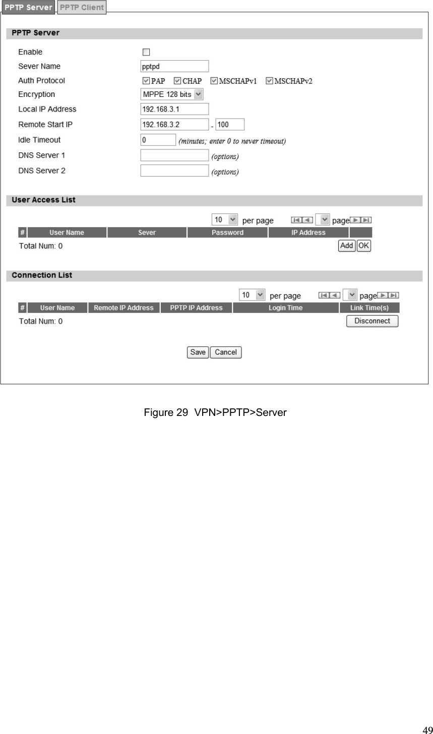
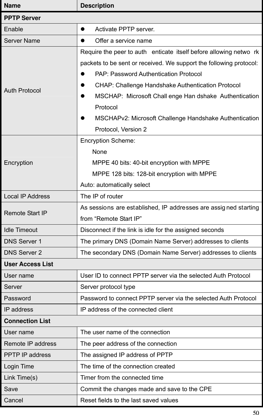
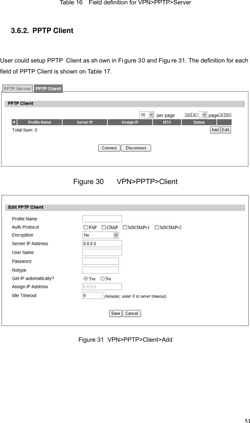
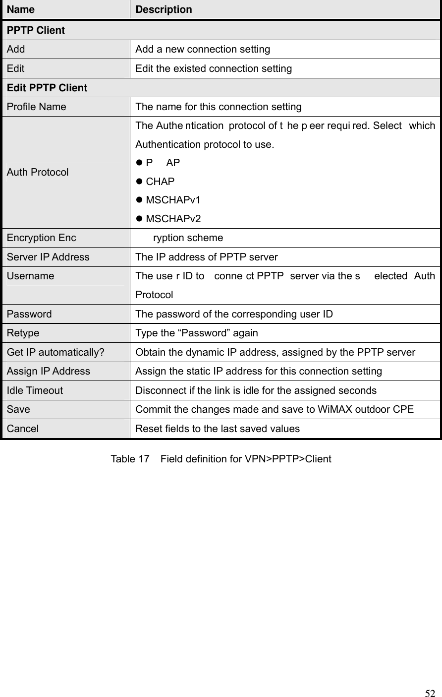
Green Packet Berhad OX250-GP Outdoor WiMAX CPE User Manual 0 5
Green Packet Berhad, Taiwan Outdoor WiMAX CPE 0 5
UserManual.wiki
>
Green Packet Berhad
>
OX250 GP User Manual
User Manual
Navigation menu
Upload a User Manual
Namespaces
Wiki Guide
HTML
PDF
Info
Views
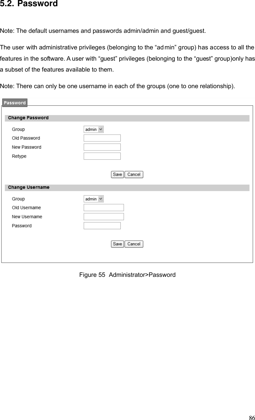
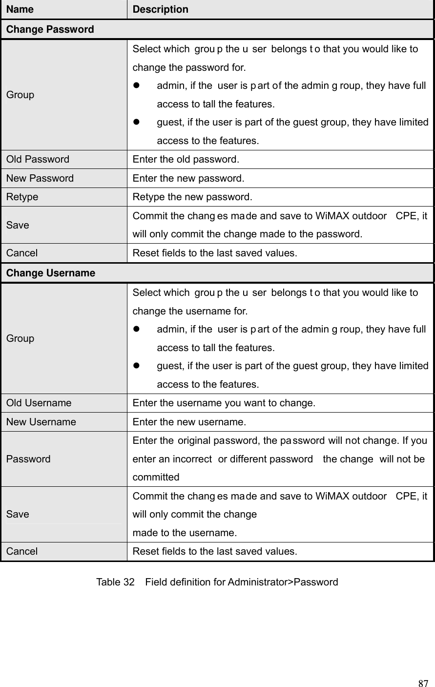
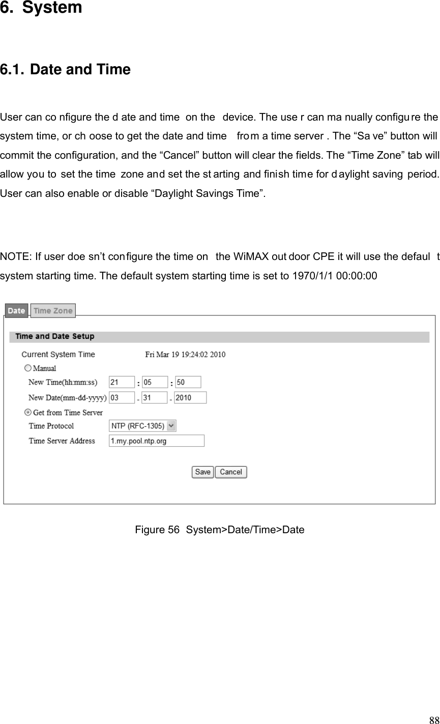
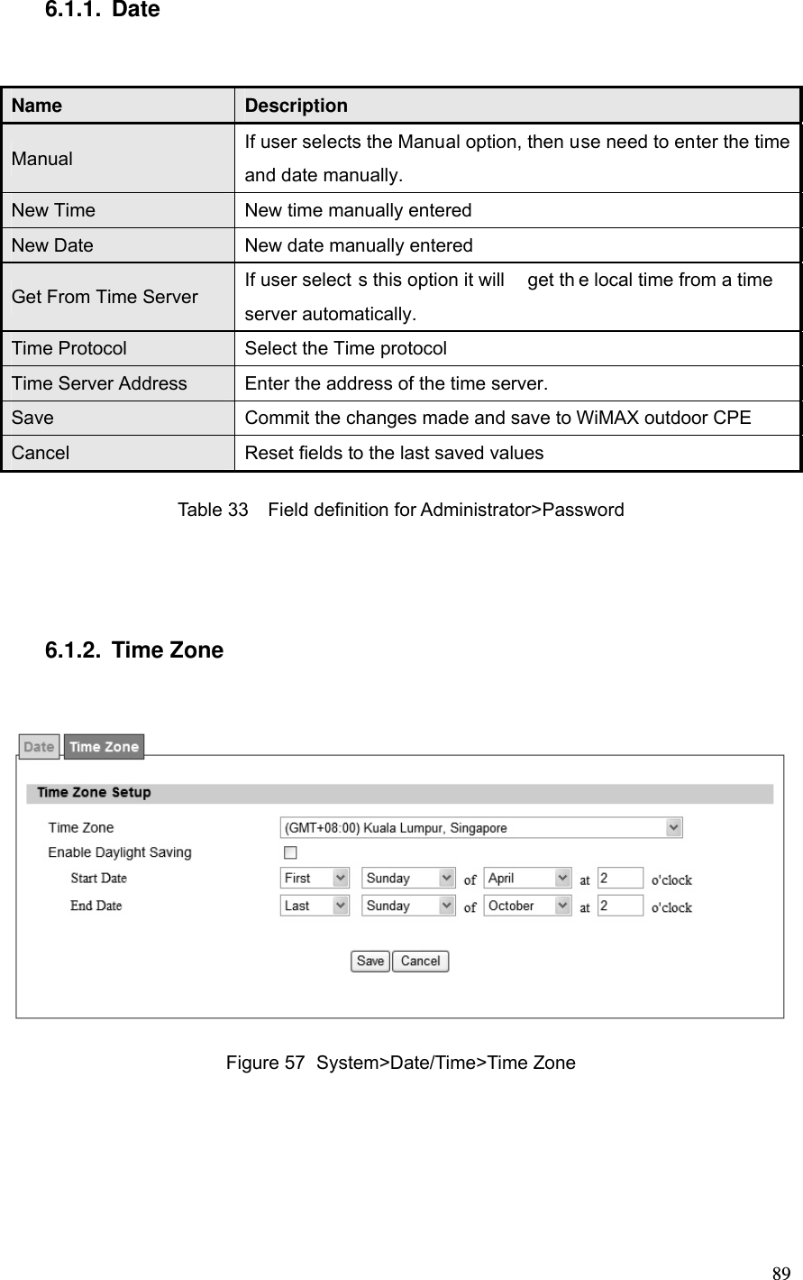
User Manual
Discussion / Help
Navigation